Embed Size (px)
Citation preview

Rev 13b Page 1 11 August 2013
Canard Fuel Probe
System Installation By Nick Ugolini
Table of Contents
1. Electronic Modules ...................................................................................................... 3 1.1 Fuel Selection Calibration...................................................................................... 4
2. Installation Time .......................................................................................................... 4 3. Inspection Of Probe ..................................................................................................... 5 4. Retrofitting a Completed Strake .................................................................................. 5
4.1 A couple of considerations for installation of the probes ...................................... 6 5. INSTALLATION IN AN EXISITING PLANE ..................................................................... 7
5.1 Preparation: ............................................................................................................ 7 6. Preparing The Strakes Opening ................................................................................... 8 7. Fishing the wires .......................................................................................................... 9 8. For New Strake Installation ....................................................................................... 13 9. Opening The Tanks .................................................................................................... 16 10. Probe Measurement/Installation .............................................................................. 17 11. Wiring The Electronics ............................................................................................ 18 12. Testing The Electronics (CRITICAL OPERATION)............................................. 21 13. Floxing The Probes In Place .................................................................................... 22 14. Purchasing ................................................................................................................ 25 15. Manditory Change ................................................................................................... 26 16. Changing Set-point Modes ...................................................................................... 27

Rev 13b Page 2 11 August 2013
Background These probes are designed to be quickly and easily installed in any Rutan or Velocity strake of a new construction or completed canard aircraft. The probe length has been sized for the average depth of the strake the aircraft. They can be adjusted shorter if needed. If you need a longer one, it will have to be custom made. 7 3/8” long - Varieze, LongEZ, Cozy 3 and 4: 8 ½” long - Velocity: 9 ¾” long - Velocity XL 11 ¼” long - Defiant: The probe measures .25” from the flange to the top of the probe sense wire and can easily fit within the 10 mm (3/8”) foam core of the strake. Once placed in the strake the probe is completely encapsulated in wet flox to seal the probe to the structure. The fuel does not need to be drained from the tank and if properly installed, leak retesting of the fuel tanks should not be required.
The following epoxies have been tested and approved for the installation of the fuel probes. WEST, MGS and E-Z Poxy.
• West and MGS can be used with AVGAS and non-ethanol MOGAS fuels. • E-Z Poxy can be used with any fuel. When in doubt I always recommend using
E-Z Poxy.

Rev 13b Page 3 11 August 2013
1. Electronic Modules
Electronics for the probes are designed, supported, supplied and warrenteed by Princeton Technology. Contact Todd Stehouwer at: [email protected]) or phone (616 243-8800) for warentee or technical questions reguarding the modules.
These electronic modules are specifically designed to work with the shorter canard style probes and can be used with any electronic flight systems or fuel gauge which utilizes a 0-5 volt fuel voltage input signal (0 is empty, 5v is full).
The electronic modules can be easily configured or reconfigured at any time by the user for three different types of outputs profiles. See the attachment at the end of the installation instructions on how to do so.
Single set point. The easiest to calibrate and is used for displays such as Grand Rapids EFIS and Dynon or any display that uses internal software to map the shape of the fuel tank. You only need to fill the empty tank to the desired “empty” point (low fuel reserve) and set the empty point. There is no need to fill your tank, calibrate the probe in steps or set the “full” point. Mapping of the tank is done at the display. The drawback is a very slight reduction is accuracy.
Two set point: Is used for displays such as Grand Rapids EFIS and Dynon and any display that uses internal software to map the shape of the fuel tank. You need to fill the empty tank to the desired “empty” point (lowest fuel reserve) and set the empty point. You must then FILL the tank to the “Full” point and set the level in the module. There is no need to calibrate the probe in steps. Mapping of the tank is done at the display.
Rev 13b Page 4 11 August 2013
There is a slight improvement of the system accuracy as opposed to the 1 set point module but take a bit more effort to set up.
Five set point: Is used for direct readouts or equipment which does not have tank mapping capability such as when using the Grand Rapids Engine Monitor, the Aircraft Extras AG6 display or other types “non-calibratable” displays. The 5 set point module electronically maps the shape of the fuel tank for the readout display. The module adjusts the voltage output depending on the shape of the fuel tank at specific points (Empty, ¼, ½, ¾, and Full) as determined during the initial calibration of the module when filling your tank. You will need to fill the empty tank to the desired “empty” point (low fuel reserve) and set the empty point. Then fill the tank in steps to the “Full” point. This will “map” the tank for the display. Calibration points are stored in the modules non-volatile memory
If you have any questions about the modules, PLEASE contact Princeton, as I only build the mechanical probe assembly and can not provide you any help on module configuration selection, trouble shooting, electrical issues, etc.
1.1 Fuel Selection Calibration
The modules can be calibrated for your choice of AVGAS, MOGAS or Diesel (Jet A). You have to choose one fuel as the primary fuel since each one has different dielectric characteristics. The fuel level will not read accurately (30-40% error) if calibrated for AVGAS and you put in a tank of MOGAS.
NOTE: These probes are difficult but not impossible to remove. Once installed they should be considered a permanent part of your structure. Due to the simple design there should never be a need to remove them. If you accidentally cut and can not repair the signal or ground wire, you will have to install a new probe (you can still use the same electronics). You will have to purchase a new signal wire from Princeton.
NOTE: It is possible to remove the probe without damaging the plane structure. You will end up destroying the probe which can be replaced. The need to do so has only occurred once when a builder used too much flox and obstructed the vent hole. Contact me privately for instruction on how to remove the probe.
2. Installation Time
Installation of the two probes should take less than 8 hrs for a flying plane depending on the type of finishing you want to do. This is a generalized installation instruction since every plane is build slightly different by the original builders.

Rev 13b Page 5 11 August 2013
3. Inspection Of Probe Vent Hole
If you purchased your probes before May 2013, inspect the probe to see if it has a small 1/16” vent hole. If YES, you must preform the Mandatory change as detailed at the end of the instructions to reduce the possibility of epoxy obstruction during installation.
4. Retrofitting a Completed Strake
NOTE: Select a location that does not interfere with the fuel strainer when inserted.
You should also choose a location for the probe which allows you to thread the signal wire through the strake foam into the cabin area. The ideal spot would a location which does not impact the fuel strainer, and is close to the sight glass.
For the installation in my plane, I selected a point 15” forward of the aft end of the spar and 5” outboard of the canopy sides. This spot is close to where my sight glasses are located so the visual fuel level and the indicated level would more or less correspond. The wire chase was drilled in at an angle such that the wire exited at the point which the longerons narrow. The electronics were placed in the passenger headrest area. Where you install your fuel probes and electronics is entirely your choice.
Point at which longeron narrows

Rev 13b Page 6 11 August 2013
A cut away view this is what the installation would look like.
Longeron Strake foam Signal wire Probe
4.1 A couple of considerations for installation of the probes
• IF you do NOT wish to immediately repaint, o Just protect the paint around your hole with some tape prior to cutting the
hole and install as shown. When cured, remove the protective tape/paper for an unblemished paint job. Make a painted Alum cover (like wing bolt covers) and RTV it over the probe hole. Save the painting till later.
o As an alternative, you could mask the area off, carefully cut an opening with a Fein saw, pry up the small square of strake skin, and then carefully reposition the skin when floxing the probe into place leaving a small thin line cut line when finished.
• IF you wish to immediately repaint the area, first mark the opening, take a sander and feather the micro back from the opening a 1/2″ or so, THEN cut the hole.
WET FLOX
Rev 13b Page 7 11 August 2013
5. INSTALLATION IN AN EXISITING PLANE
The following pictures and installation shown was performed on my LongEZ which will not be repainted and the strake skin will be reused as a cover.
5.1 Preparation:
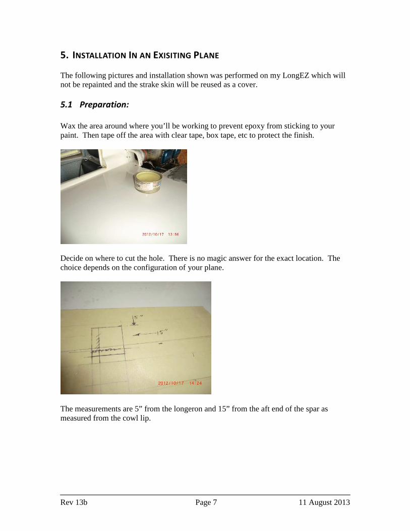
Wax the area around where you’ll be working to prevent epoxy from sticking to your paint. Then tape off the area with clear tape, box tape, etc to protect the finish.
Decide on where to cut the hole. There is no magic answer for the exact location. The choice depends on the configuration of your plane.
The measurements are 5” from the longeron and 15” from the aft end of the spar as measured from the cowl lip.

Rev 13b Page 8 11 August 2013
6. Preparing The Strakes Opening
When you have selected the location for your probe, mark and cut the outer skin of the strake. I would suggest about a 1 1/4” opening. Remove the outer skin and the foam to the inner skin.
Hint: If you put some tape your Fein saw ¼” bade away from the edge it will create a depth gauge on the blade. This will ensure you will not cut into the inner skin of the tank.
After you cut the skin, take a razor knife and check the cut to ensure the square is free all the way around the perimeter.
Then stick the blade under the edge and pry the square off the foam.
Remove about 1/4” of foam from the underside of the hole. Bevel the upper skin at a slight angle if you intend to use a layer of BID after floxing the hole (if you wish to

Rev 13b Page 9 11 August 2013
repaint the area otherwise level it square cut). Leave the edge square if you intend to replace the skin cutout as I did on my installation.
Next you’ll have to feed the wires through the foam.
BE CAREFUL you do not drill into your fuel tank.
7. Fishing the wires
Before fishing your wires through the hole, carefully remove all remnants of the strake foam from the inner skin of the full tank. I found a flat ½” wood chisel ideal for scraping the inner skin to remove the foam and micro and finally vacuum the surface.
I would suggest taking some 1/8” welding wire and flatten then file the end into a wedge and drill a small hole in the flattened area so later you can insert some safety wire into the little hole to use to pull your wires through the hole.
Small hole drilled for safey wire.
Removed
Bevel edge FG Skins

Rev 13b Page 10 11 August 2013
When you push the welding wire through the foam depending how you orient the wedge, you can steer the wire. If you keep the wedge oriented with the sharp point near the upper shin, when you push the wire through the foam, the wedge will force the wire upward and follow the upper skin. You steer the wire using the same technique as used in directional drilling.
Hint: The direction of the wire can easily be monitored by taking a small magnet (like a small high strenght rare earth magnet) and placing it near the tip as you push the wire through the foam. I used a magnet which was intended to hold on a shirt name tag. It will easily track the steel wire under the skin.
This is how the wire would look as it travels through the foam. The wire will be forced upward (due to the wedge) to travel just under the upper skin.
To drill though the side wall skins, I used the other end of the wire which was ground to a shallow point and sharpened using a file to look like the end of a drill bit.

Rev 13b Page 11 11 August 2013
Now insert your home made drill bit into the channel you just made and you can easily bore through the exterior and interior glass sides of the fuselage (2 layers of UNI per side). You might also just try spinning the wedge with the drill motor. It should drill through the glass.
Attach some .020” safety wire into hole which was drilled in the wedge and pull it back though the hole you just created (from the cabin to the hole). You may have to enlarge the hole in the cabin slightly as the welding wire is only 1/8” in diameter. I used a 3/16” bit to enlarge the hole.
Then attach some Teflon wire to be used as the ground (I used #24) to the safety wire and pull it back through the hole (from the outside hole to the cabin). I made a loop of the Teflon wire so there would be two wire though the hole. One will be the ground and the other will be used to pull the coax wire.
Rev 13b Page 12 11 August 2013
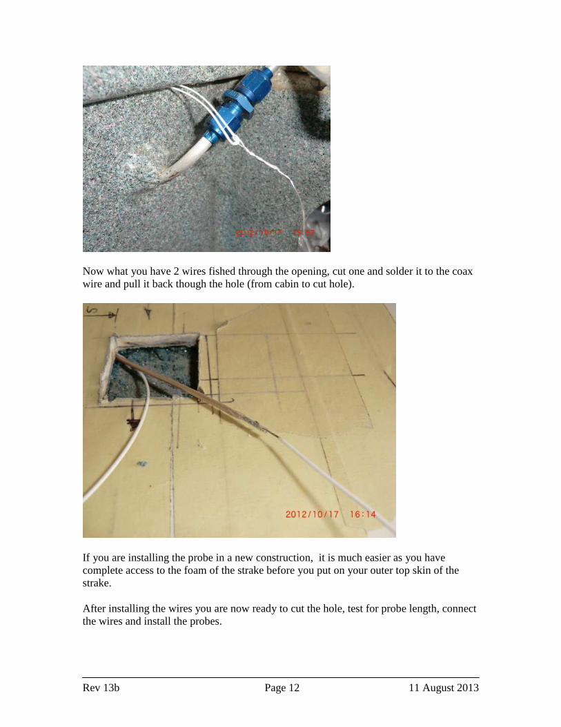
Now what you have 2 wires fished through the opening, cut one and solder it to the coax wire and pull it back though the hole (from cabin to cut hole).
If you are installing the probe in a new construction, it is much easier as you have complete access to the foam of the strake before you put on your outer top skin of the strake.
After installing the wires you are now ready to cut the hole, test for probe length, connect the wires and install the probes.

Rev 13b Page 13 11 August 2013
8. For New Strake Installation
Installing the probes in a new installation is extremely easy and requires much less effort than retrofitting a completed plane.
Mark your probe location. Be sure you have sufficient clearance away from the fuel strainer and vent lines to prevent the probe from touching them.
Drill a 3/16” hole into the cabin. Ensure you do not drill into your fuel tank.
Remove the foam.

Rev 13b Page 14 11 August 2013
Create a channel for the wires.
The prep work is finished. Now use a razor knife to cut your hole for the fuel probe.

Rev 13b Page 15 11 August 2013
Wire the probe and you are done. Total for this install time was about 15 minutes. Now you are ready to complete the probe installation by verifying probe length and testing the probes electronics prior to final glassing the outer skin of the strake.
NOTE: Be sure the probe is completely encapsulated with flox when glassing the strake to prevent fuel leaks.

Rev 13b Page 16 11 August 2013
9. Opening The Tanks
CAUTION: I have installed the probes (cutting open the tanks) with fuel in the tank. I
do recommend draining and venting the fuel tank. Be aware that an empty tank with fuel vapors is just as dangerous as a partially full tank. Be sure to not use any electrical equipment while the small hole is open in the strake and keep your fire extinguisher close at hand.
Using a razor knife, cut a square opening in the glass inner skin of the strake for the probe tube. The razor knife is used to prevent getting chips into the tank which wound invariably happen if a hole is drilled. After you cut the 3 sides of the hole, bend the tab up and break it off…. no chips.

Rev 13b Page 17 11 August 2013
10. Probe Measurement/Installation
After the hole is cut in the tank to ensure the length of the probe is appropriate for your strake (since each strake thickness is different). Take a piece of welding rod (or coat hanger) and insert it into the hole to the bottom of the tank to test the depth of the strake at your installation location. The probes are exactly 7 3/8” long and will fit a standard Rutan strake. Velocity probes are 8.5” long. Contact me if you need a custom size.
Measure the depth of the tank and compare it to the length of the probe. If necessary, disassemble and shorten the probe by using a disk sander to allow for about ¼” clearance from the bottom of the tank,
TIP: An easy way to shorten the probe is to remove the center electrode from the main probe, slide all the small triangular spacer toward the connection end (to prevent melting), and reinsert the center electrode back into the probe. Sanding both tubes at the same time supports the inner tube with the outer tube and they will both end up exactly the same length.
After shortening, disassemble the probe and reposition the spacers and check the length.
If you need reposition the bottom triangular separator after shortening the probe. Position the separator about 1/8” from the bottom and carefully crimp both sides of the tube adjacent to the separator to hold it in position.
Rev 13b Page 18 11 August 2013
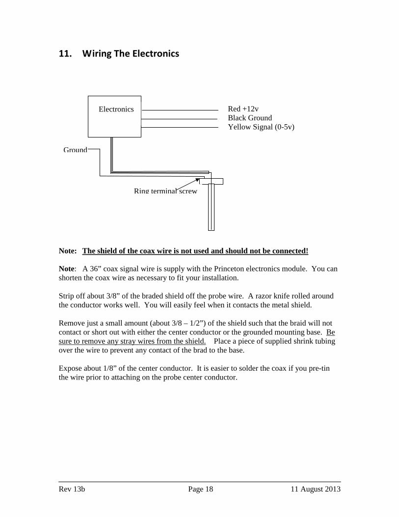
11. Wiring The Electronics
Note: The shield of the coax wire is not used and should not be connected! Note: A 36” coax signal wire is supply with the Princeton electronics module. You can shorten the coax wire as necessary to fit your installation.
Strip off about 3/8” of the braded shield off the probe wire. A razor knife rolled around the conductor works well. You will easily feel when it contacts the metal shield.
Remove just a small amount (about 3/8 – 1/2”) of the shield such that the braid will not contact or short out with either the center conductor or the grounded mounting base. Be sure to remove any stray wires from the shield. Place a piece of supplied shrink tubing over the wire to prevent any contact of the brad to the base.
Expose about 1/8” of the center conductor. It is easier to solder the coax if you pre-tin the wire prior to attaching on the probe center conductor.
Red +12v Black Ground Yellow Signal (0-5v)
Ground
Ring terminal screw
Electronics

Rev 13b Page 19 11 August 2013
Note: Be sure to gently push the center insulator down on the center electrode to keep from overheating and melting the plastic prior to soldering. There is a recess pocket on the insulator and a crimp on the electrode to keep it from going down too far into the insulator.
Note: The center probe tube is pre-tinned to facilitate the soldering.
After soldering, position the shrink tubing over the shield wire near the center probe and shrink it. Push the insulator back up the electrode until it stops (don’t force it too hard. It has a crimp to ensure it is at the right position.

Rev 13b Page 20 11 August 2013
The probe uses the screw crimp connector with either a #22 or #24 wire as a ground, which is attached to your plane’s system ground.
Note: Prior to permanently attaching the ring terminal to the probe, sand both sides of the ring terminal and the probe area under the ring terminal to remove any Al oxide. Be sure to use the supplied star washers on the top and bottom of the ring terminal. This will ensure the best possible electrical connection for the probe ground.
If the screw sticks out to far from the base which could prevent the base from sitting flat on the inner skin, you can either add another washer or use a Dremel tool with a sanding disk to grind down the screw.

Rev 13b Page 21 11 August 2013
12. Testing The Electronics (CRITICAL OPERATION)
BEFORE you flox the probes in you MUST test them to ensure they are properly wired and operational. It is important to check out the wiring and soldered connections prior to floxing them permanently in.
1. Temporarily connect up the wires: Red to 12+, Black (of the module) and probe base wire to ground and begin the calibration procedure per the Princeton instruction.
2. If properly wired, the left LED will flash indicating the system is working and the system is beginning the start of the calibration procedure.
3. Press the calibration switch the left LED will light change from blinking to steady indicating it is calibrated for an EMPTY tank. After a few seconds go out indicating it is waiting for next set point. IF you have the 1 set point module it will begin to flash very slowly (heartbeat) indicating it has gone into normal operation.
4. If you get to this step, then your system is properly wired and working normally. Just disconnect the power and ground and complete the installation.
5 IF you get an error code on the module then there is a problem with the wiring which needs to be corrected prior to permanently floxing the probe into the tank. If you are unable to figure the problem out, please contact Princeton to identify what steps may be necessary to correct the electrical issue. For electronic/electrical issues, I can not help you and you need to contact Princeton directly for assistance.

Rev 13b Page 22 11 August 2013
13. Floxing The Probes In Place
Mix some very dry flox, and put a small amount just at the outside edge of the of bottom side of the probe to create a seal to prevent the wet epoxy from flowing under the base.
NOTE: Be very careful not use too much flox on the base which could squish out into the tank and obstruct the vent hole located at the top of the probe.
The purpose of the dry flox on the bottom of the probe is to hold the base in position and to prevent the wet flox which seals the probe in place to not flow into the tank thus obstructing the vent hole.
Install the probe into the tank and fill the entire cavity with wet flox. The probe/wires should be completely encapsulated (potted) into the tank with wet flox. Be sure to allow enough contact area of the inner skin beyond the probe to allow for a good seal around the probe perimeter.
After filling the probe area, you can reposition your square cutout of the strake back into the hole. I would recommend allowing the flox cure until it is a bit firm before you put the cover in place. This way the cover will not settle into the wet flox and makes positioning it easier.

Rev 13b Page 23 11 August 2013
After curing, remove all the protective tape, sand the area with 1200 grit, buff it out and it will look great!
If you are not using the cutout, put 1 layer of BID in the wet flox and let all cure. The BID will attach the beveled edge of the opening and the undercut you made in the foam.

Rev 13b Page 24 11 August 2013
If you plan to repaint the plane, just sand the area flush after cure, micro, sand and paint.
After installation a little paint they are completely gone.
Alternatively, until you repaint the area you could make a cover out of some thin aluminum painted to match your plane and RTV it in place if you don’t use the skin piece you removed at the start of the installation.

Rev 13b Page 25 11 August 2013
14. Purchasing
If you are interested, my contact email is [email protected] You can also call me at 843-608-9250
• A standard system (VariEZE, LongEZ, Cozy 3 and 4) sells for $165 per side. • A extra long system (Velocity XL and Defiant) sells for $170 per side. • The Princeton electronic modules are only avaliabe from me for $100 each if you
purchased your probes without electronics. • Shipping is a flat $10
Example: Total cost of the a standard two probe system shipped anywhere in the US is $340.00. Shipping to foreign countries will be slightly higher to cover the additional cost.

Rev 13b Page 26 11 August 2013
15. Manditory Change for probes purchased before May 2013
Due to some installers inadvertently plugging the vent hole at the top of the probe during installation, it is mandatory that you enlarge the vent hole to reduce the possibility of the hole being plugged with wet flox. If for any reason you feel your probe is plugged, I will supply a new probe free of charge. You must return the removed probe to me. All probes shipped after 5/1/2013 have the larger vent holes and this AD does not apply Procedure:
1. Remove the center electrode from the probe 2. Use a 1/8” drill to enlarge the vent hole
3. Remove all burs, both on the outside and the inside of the tube. Use a slightly
undersized drill and HAND scrape the inside of the tube to remove burs.
Inspect for burs after cleaning, reassemble probe and install in the plane.

Rev 13b Page 27 11 August 2013
16. Changing Set-point Modes
The Princeton configuration setup instructions apples to the new multi-set point modules which became available after Oct 2012. For modules purchased prior to Oct 2012, the module has to be sent back to Princeton to change set point modes.
LongEZ Multi Set-point Suplemental Instructions
The multi set-point feature of this probe allows th e selection of IS, 2S and 5S modes.
IS (Calibrate Empty).- The output will be 0 volts for empty and approxim ately 1.5 to 3.5 volts for full.- Used by Dynon and Advanced Flight EFIS systems.- Can be used by Grand Rapids Technologies EFIS als o.- Has the advantage of not having to empty the tank s to calibrate the EFIS.
2S (Calibrate Empty and Full)- The output is 0 volts for empty and 5 volts for f ull. It is linear between.- Grand Rapids Technologies and Chelton EFIS system s.- Used with analog gauges, and some EFIS systems th at use a calibration table.- Gives greater voltage range on the output.
5S (Calibrate Empty, '/S, '/a, %, and Full)- Used with analog gauges, and some EFIS systems th at use a calibration table.- Grand Rapids Technologies and Chelton EFIS system s.- Linearizes the output for analog gauges.- For an EFIS enter a linear chart in the table.
- Gives greater voltage range on the output.
To select the set-point setting: - — . —______ ___ .,_.1) Power off to the module.2) Short the output (Yellow wire) to ground.3) Press and hold down the button.4) While holding the button down turn power on.5) After 10 seconds the lights will turn off. Keep button pressed.6) The left light will come on, then it will shift to the middle, then the right light, then all light s
off. It will repeat this continually until you let go of the button.7) Release the button when the appropriate light is on.8) Turn off the power and remove short to ground fr om the output.
Left light =1SMiddle light = 2SRight light =5S

Rev 13b Page 28 11 August 2013
1. Attachment: Calibration instructions
This instruction is to be used for all electronic modules (new and old)
PRINCETON CAPACITIVE FUEL LEVEL PROBES3133 Madison Ave, Wyoming, MI 49548 (616)243-8800
Theory of operationThe probe senses a change in fuel level using a cap acitive sensorformed by two metal conductors. No current passes t hrough thefuel. The aluminum outer tube is at ground potentia l through anisolation capacitor. The inner brass rod has a sign al on itthrough a I Meg ohm resister. There is a digital mi croprocessorthat filters and conditions the signal providing a very stable fuellevel reading.
The leads from the probe are protected from miss wi ring of theprobe. The supply voltage can be from 10 to 28 volt s continues.
Probe operationThe probe has two modes of operation, calibration a nd run. Theprobe comes from the factory in the calibration mod e. Tocalibrate the probe see the calibration instruction s.
When power is applied and the probe has been calibr ated theprobe will perform a self-test sequence. The middle light flashesquickly while this process takes place. The output of the probewill go to full for 1 second and then empty for 1 s econd. Thisallows a visual test of both the gauge and the prob e for properoperation. The output is filtered with a RC network andtherefore does not change rapidly. The gauge will r ead ftill verybriefly. After the self-test a heartbeat will flash every 2 secondson the middle light. The current level is updated w ithoutaveraging to get a reading quickly at power-up.
The output of the probe is digitally filtered by tw o methods. Thefirst is an_ayeraging function. Readings are averag ed for 60seconds before being passed to the second digital f ilter. Thistype of filtering works well with fuel because of l ow frequencysloshing. With float type probes this is seen in th e indicatorrocking back and fourth. The averaging method elimi nates this.
The second digital filter is a low pass filter that behaves like aRC filter with a long time constant. The output wil l changeslowly. The main benefit from this filter is the el imination ofhigh frequency oscillations.
Because of the filtering used the fuel level readin g will be verystable. It can take up to 120 seconds to update an actual changein fuel quantity. Even while filling the tank this is not aproblem.
I.KillTS
BUTTON
§§i
MANUFACTURING
CONNF.CTOR
WIRE CONNECTIONS
INTERFACE MODULE
RED
BLACK
YELLOW
MALF."FAKRA"SMB
wumligikcvcom ARFI253-ND
- +I2V10+28V
- Ground
- Signal (0 to SV)
- Probe
Sun
•i*i 3<4»jv :•;-»>* ; ,7XtfV^«^W««'*>«r^^;'--^*3^|frW^';»*
WIRE CONNECTIONS
PROBE
Terminal - Ground
"FAKRA" SMB coax connector - Electronics\\\v\vdigil(cvcomARFI250-ND
•ͣ/•>>'*£*'

Rev 13b Page 29 11 August 2013