Embed Size (px)
Citation preview

Canadian Mental Health Association
Muskoka-Parry Sound Branch 60 James Street, Parry Sound, Ontario
138 SIMCOE STREET | PETERBOROUGH | ONTARIO | K9H 2H5
Specifications – Volume 2 of 2 Project No. 12-134 Date of Issue: April 5, 2018 Issued for: Tender John Angus & Associates Inc. Mechanical Engineering Consultants
Lonergan Engineering Inc. Electrical Engineering Consultants
SpecTech Communications Consultants
Specifications Volume 1 of 2 Project No. 12-134 Date of Issue: February 14, 2013 Issued for: Review

Canadian Mental Health Association PROFESSIONAL CERTIFICATIONS Muskoka-Parry Sound Branch Section 00 01 07 60 James Street, Parry Sound, Ontario Page 1 of 1
Lett Architects Inc. 12-160
CONSULTANT'S SEAL This seal governs all Documents and Sections of these Specifications, except Section 00 30 00 – Existing Conditions and all divisions/sections listed below.
MECHANICAL SUBCONSULTANT'S SEAL This seal governs : Division 21 – Fire Suppression (all Sections) Division 22 – Plumbing (all Sections) Division 23 – HVAC (all Sections) Division 25 – Integrated Automation (all Sections)
ELECTRICAL SUBCONSULTANT'S SEAL This seal governs : Division 26 – Electrical (all Sections) Division 27 – Communications (all Sections) Division 28 – Electrical Safety & Security (all Sections)

Canadian Mental Health Association TABLE OF CONTENTS Muskoka-Parry Sound Branch Section 00 01 10 60 James Street, Parry Sound, Ontario Page 1 of 4
Lett Architects Inc. 12-134
SECTION NO. TITLE .............................................................................. NO. OF PAGES ........... CERT. VOLUME 1 OF 2 DIVISION 00 PROCUREMENT AND CONTRACTING REQUIREMENTS 00 01 07 Professional Certifications ...................................................................... 1 00 01 05 Project Directory ..................................................................................... 1 00 01 10 Table of Contents ................................................................................... 4 00 01 15 List of Drawings ...................................................................................... 1 00 21 13 Instructions to Bidders .......................................................................... 12 00 30 00 Existing Conditions ................................................................................ 1 Designated Substance & Hazardous Materials Investigation ............... 37 00 41 13 Stipulated Price Bid Form ....................................................................... 8 00 60 00 Project Forms ......................................................................................... 1 00 73 00 Supplementary Conditions ...................................................................... 7 DIVISION 01 GENERAL REQUIREMENTS 01 10 00 Summary of Work ................................................................................... 1 .................... A 01 21 00 Allowances .............................................................................................. 1 .................... A 01 29 00 Payment Procedures .............................................................................. 2 .................... A 01 30 00 Administrative Requirements .................................................................. 6 .................... A 01 31 23 Interference and Coordination Drawings and Documents ...................... 3 .................... A 01 32 33 Photographic Documentation ................................................................. 1 .................... A 01 40 00 Quality Requirements ............................................................................. 5 .................... A 01 41 00 Regulatory Requirements ....................................................................... 1 .................... A 01 42 00 References ............................................................................................. 2 .................... A 01 50 00 Temporary Facilities and Controls .......................................................... 5 .................... A 01 51 16 Temporary Fire Control ........................................................................... 2 .................... A 01 57 19 Temporary Environmental Controls ........................................................ 4 .................... A 01 58 00 Project Identification ............................................................................... 1 .................... A 01 61 00 Common Product Requirements ............................................................ 5 .................... A 01 70 00 Execution Requirements ......................................................................... 3 .................... A 01 74 00 Cleaning and Waste Management ......................................................... 2 .................... A 01 77 00 Closeout Procedures .............................................................................. 3 .................... A 01 78 00 Closeout Submittals ................................................................................ 5 .................... A DIVISION 02 EXISTING CONDITIONS 02 41 19 Selective Demolition ............................................................................... 5 .................... A DIVISION 03 CONCRETE 03 01 00 General Concrete Work .......................................................................... 6 .................... A DIVISION 04 MASONRY 04 22 00 Concrete Unit Masonry ........................................................................... 6 .................... A DIVISION 05 METALS 05 50 00 Metal Fabrications .................................................................................. 4 .................... A DIVISION 06 WOOD, PLASTICS AND COMPOSITES 06 10 00 Rough Carpentry ................................................................................... 4 .................... A 06 20 00 Finish Carpentry ..................................................................................... 5 .................... A 06 41 00 Architectural Wood Casework ................................................................ 9 .................... A

Canadian Mental Health Association TABLE OF CONTENTS Muskoka-Parry Sound Branch Section 00 01 10 60 James Street, Parry Sound, Ontario Page 2 of 4
Lett Architects Inc. 12-134
DIVISION 07 THERMAL AND MOISTURE PROTECTION 07 21 16 Blanket Insulation ................................................................................... 2 .................... A 07 53 23 Elastomeric Membrane Roofing ........................................................... 15 .................... A 07 62 00 Sheet Metal Flashing & Trim .................................................................. 3 .................... A 07 84 00 Firestopping .......................................................................................... 11 .................... A 07 92 00 Joint Sealants ......................................................................................... 7 .................... A DIVISION 08 DOORS AND OPENINGS 08 11 13 Hollow Metal Doors & Frames .............................................................. 11 .................... A 08 14 16 Wood Doors ............................................................................................ 7 .................... A 08 71 00 Door Hardware ..................................................................................... 16 .................... A Hardware Schedule .............................................................................. 13 .................... A 08 80 00 Glazing .................................................................................................... 7 .................... A DIVISION 09 FINISHES 09 06 00 Concrete Floor Slab Preparation for Applied Finishes ............................ 3 .................... A 09 21 16 Gypsum Board Assemblies .................................................................. 10 .................... A 09 30 13 Tiling ....................................................................................................... 6 .................... A 09 51 13 Acoustical Panel Ceilings ....................................................................... 5 .................... A 09 65 13 Resilient Base and Accessories ............................................................. 4 .................... A 09 65 16 Resilient Sheet Flooring .......................................................................... 6 .................... A 09 65 19 Resilient Tile Flooring ............................................................................. 6 .................... A 09 68 16 Sheet Carpeting ...................................................................................... 7 .................... A 09 91 16 Interior Painting ....................................................................................... 7 .................... A VOLUME 2 OF 2 00 01 07 Professional Certifications ...................................................................... 1 00 01 10 Table of Contents ................................................................................... 4 DIVISION 10 SPECIALTIES 10 14 19.13 Exterior Signage ..................................................................................... 2 .................... A 10 22 26.33 Folding Panel Partitions ......................................................................... 5 .................... A 10 28 13 Washroom Accessories .......................................................................... 4 .................... A 10 56 26 Mobile Storage Shelving ......................................................................... 8 .................... A DIVISION 11 EQUIPMENT NOT USED DIVISION 12 FURNISHINGS NOT USED DIVISION 13 SPECIAL CONSTRUCTION NOT USED DIVISION 14 CONVEYING EQUIPMENT NOT USED DIVISION 21 FIRE SUPPRESSION 21 05 01 Common Work Results for Mechanical ............................................... .. 4 ................... M 21 05 02 Work in existing buildings ................................................................... ... 3 ................... M 21 07 19 Thermal Insulation Piping ................................................................... ... 8 ................... M 21 13 13 Wet Pipe Sprinkler Systems................................................................ ... 9 ................... M

Canadian Mental Health Association TABLE OF CONTENTS Muskoka-Parry Sound Branch Section 00 01 10 60 James Street, Parry Sound, Ontario Page 3 of 4
Lett Architects Inc. 12-134
DIVISION 22 PLUMBING 22 11 16 Domestic Water Piping ........................................................................ .. 5 ................... M 22 13 17 Drainage Waste and Vent Piping - Cast Iron And Copper .................. ... 3 ................... M 22 13 18 Drainage Waste and Vent Piping - Plastic........................................... ... 2 ................... M 22 42 01 Plumbing Specialties and Accessories................................................ ... 5 ................... M 22 42 03 Commercial Washroom Fixtures ........................................................ ... 3 ................... M DIVISION 23 HVAC 23 05 01 Use Of Mechanical Systems During Construction .................................. 2 ................... M 23 05 05 Installation of Pipework ........................................................................... 5 ................... M 23 05 23.01 Valves - Bronze NPS 2 & UNDER ......................................................... 4 ................... M 23 05 23.05 Bronze Valves ........................................................................................ 5 ................... M 23 05 29 Hangers and Supports For HVAC Piping And Equipment ..................... 7 ................... M 23 05 48 Vibration Isolation .................................................................................. 5 ................... M 23 05 53 Mechanical Identification ........................................................................ 5 ................... M 23 05 93 Testing, Adjusting and Balancing For HVAC ......................................... 8 ................... M 23 05 94 Pressure Testing of Ducted Air Systems ............................................... 4 ................... M 23 07 13 Duct Insulation ....................................................................................... 5 ................... M 23 08 01 Mechanical Piping Performance Verification ......................................... 3 ................... M 23 08 02 Cleaning and Start-up of Mechanical Piping Systems ........................... 4 ................... M 23 09 00 Control System For HVAC .................................................................... 17 ................... M 23 09 33 Electronic Control System For HVAC ..................................................... 3 ................... M 23 11 23 Facility Natural Gas Piping ..................................................................... 4 ................... M 23 31 13 Metal Ducts - Low Pressure To 500 Pa .................................................. 5 ................... M 23 33 00 Air Duct Accessories .............................................................................. 7 ................... M 23 33 14 Dampers - Balancing ............................................................................. 2 ................... M 23 33 16 Dampers - Fire and Smoke .................................................................... 3 ................... M 23 33 46 Flexible Ducts ........................................................................................ 2 ................... M 23 33 53 Duct Liners ............................................................................................. 3 ................... M 23 34 00 HVAC Fans ............................................................................................ 5 ................... M 23 34 24 Domestic Fans ....................................................................................... 5 ................... M 23 36 00 Air Terminal Units .................................................................................. 4 ................... M 23 37 13 Diffusers, Registers and Grilles .............................................................. 3 ................... M 23 73 11 Packaged Rooftop Built-up Air Handlers ............................................... 6 ................... M DIVISION 26 ELECTRICAL 26 01 01 Electrical General Requirements .......................................................... 23 .................... E 26 01 00.00 Operating and Maintenance Instruction ................................................. 3 .................... E 26 05 01.00 General Instructions for Electrical Sections ......................................... 12 .................... E 26 05 03.00 Record Drawings ................................................................................... 3 .................... E 26 05 04.00 Submittals/Shop Drawings ..................................................................... 2 .................... E 26 05 05.00 Mounting Heights ................................................................................... 2 .................... E 26 05 21.00 Wires and Cables 1000V ....................................................................... 5 .................... E 26 05 31.00 Splitters, Junction, Pull boxes and Cabinets .......................................... 2 .................... E 26 05 32.00 Outlet Boxes, Conduit Boxes and Fittings ............................................. 3 .................... E 26 05 34.00 Conduits, Conduit Fasteners and Fittings .............................................. 4 .................... E 26 05 40.00 Poke - Thru Devices .............................................................................. 2 .................... E 26 05 53.00 Identification ........................................................................................... 3 .................... E 26 05 83.00 Sleeves .................................................................................................. 2 .................... E 26 05 88.00 Cutting and Patching ............................................................................. 1 .................... E 26 09 24.00 Lighting Control Equipment - Low Voltage ............................................ 3 .................... E 26 12 17.00 Dry Type Transformers - 600V Primary ................................................. 3 .................... E 26 12 18.00 Harmonic Mitigating Dry Type Transformers - 600V Primary ................ 4 .................... E 26 27 17.00 Panelboards - Breaker Type .................................................................. 3 .................... E 26 27 26.00 Wiring Devices ....................................................................................... 4 .................... E

Canadian Mental Health Association TABLE OF CONTENTS Muskoka-Parry Sound Branch Section 00 01 10 60 James Street, Parry Sound, Ontario Page 4 of 4
Lett Architects Inc. 12-134
26 28 14.00 Fuses - Low Voltage .............................................................................. 2 .................... E 26 28 23.00 Disconnect Switches - Fused and Non-Fused ....................................... 2 .................... E 26 51 13.00 Lighting Equipment ................................................................................ 7 .................... E 26 52 01.00 Unit Equipment for Emergency Lighting ................................................ 3 .................... E DIVISION 27 COMMUNICATIONS 27 00 03 General Specifications and Requirements for Communications ........... 3 ................... C 27 00 05 Definitions and Abbreviations for Communications ............................. 11 ................... C 27 00 07 Codes and Standards for Communications ......................................... 18 ................... C 27 00 09.10 Scope of Work for Structured Cabling Communications ..................... 22 ................... C 27 00 11 Administrative Requirements for Communications .............................. 25 ................... C 27 00 13 Fire Stopping for Communications ...................................................... 28 ................... C 27 05 26 Grounding and Bonding for Communications ...................................... 32 ................... C 27 05 28 Pathways for Communications ............................................................ 38 ................... C 27 05 53 Identification for Communications ......................................................... 44 ................... C 27 06 10 Schedules for Structured Cabling and Enclosures .............................. 47 ................... C 27 08 00.10 Commissioning of Structured Cabling System .................................... 48 ................... C 27 11 16 Communications Cabinets, Racks, Frames and Enclosures ................ 53 ................... C 27 11 19 Communications Termination Blocks and Patch Panels ..................... 56 ................... C 27 11 23 Communications Cable Management and Ladder Rack ..................... 58 ................... C 27 13 13 Communications Copper Backbone Cabling ....................................... 60 ................... C 27 13 23 Communications Optical Fibre Backbone Cabling .............................. 63 ................... C 27 15 13 Communications Copper Horizontal Cabling ....................................... 66 ................... C 27 15 43 Communications Faceplates and Connectors ..................................... 68 ................... C 27 16 19 Communications Patch Cords and Cross-Connect Wire ...................... 71 ................... C 27 00 00.10 Structured Cabling Communications Tender Form ................................ 4 ................... C DIVISION 28 ELECTRONIC SAFETY AND SECURITY 28 00 03 General Specifications and
Requirements for Electronic Safety and Security .................................. 3 ................... C 28 00 05 Definitions and Abbreviations for Electronic Safety and Security ........ 12 ................... C 28 00 07 Codes and Standards for Electronic Safety and Security ..................... 19 ................... C 28 00 09 Scope of Work for Electronic Safety and Security ............................... 23 ................... C 28 00 11 Administrative Requirements for Electronic Safety and Security .......... 25 ................... C 28 00 13 Fire Stopping for Electronic Safety and Security ................................. 28 ................... C 28 00 15 Electronic Safety & Security Cable
& Equipment Removal Requirements ................................................. 32 ................... C 28 05 13.13 CCTV Communications Conductors and Cables .................................. 34 ................... C 28 05 13.16 Access Control Communications Conductors and Cables .................. 35 ................... C 28 05 13.19 Intrusion Detection Communications Conductors and Cables ............ 37 ................... C 28 05 26 Grounding and Bonding for Electronic Safety and Security ................. 38 ................... C 28 05 28 Pathways for Electronic Safety and Security ....................................... 41 ................... C 28 05 53 Identification for Electronic Safety and Security .................................. 43 ................... C 28 08 00 Commissioning of Electronic Safety and Security ............................... 45 ................... C 28 13 00 Access Control Systems ....................................................................... 48 ................... C 28 16 00 Intrusion Detection Systems ................................................................ 69 ................... C 28 23 00 Video Surveillance Systems ................................................................. 75 ................... C 28 26 13 Electronic Personal Protection Systems ............................................... 83 ................... C 28 00 00 Electronic Safety and Security Tender Form ESSTF.1 .......................... 3 ................... C 28 31 01.00 Fire Alarm ............................................................................................... 2 .................... E
END OF SECTION

Canadian Mental Health Association EXTERIOR SIGNAGE Muskoka-Parry Sound Branch Section 10 14 19.13 60 James Street, Parry Sound, Ontario Page 1 of 2
Lett Architects Inc. 12-160
1 GENERAL 1.1 GENERAL REQUIREMENTS
.1 The General Conditions of the Contract, Supplementary Conditions, and the General Requirements of Division 1, form part of this section, and must be read in conjunction with the requirements of this section. The work of this section shall comply with all requirements of Division 1 – General Requirements.
.2 The Contractor shall, together with any and all Subcontractors involved in the work of this
section, examine all surfaces or conditions relating to the Work, in order to determine the acceptability of such surfaces or conditions for the work of this section to commence.
.3 Subcontractors shall report in writing, any observed defects or deficiencies in any
surfaces or conditions that would adversely affect the work of this section, to the Contractor for correction prior to commencing the work of this section.
.4 Commencement of the work of this section shall imply acceptance of all surfaces and
conditions. 1.2 SECTION INCLUDES
.1 Provision of all labour, materials, equipment and incidental services necessary to provide wall-mounted exterior building signage.
1.3 SUBMITTALS
.1 Make submittals in accordance with Section 01 30 00.
.2 Samples .1 Provide one sign letter representative of type specified inappropriate size and
colour.
.3 Shop Drawings .1 Submit shop drawings. Clearly indicate material and large scale details showing
anchor types, letter types, finishes and methods of installation. 1.4 QUALITY ASSURANCE
.1 Manufacturer/Fabricator .1 Manufacturers or fabricators providing Products under this Section shall have
sufficient plant, equipment and competent personnel to provide the Products, in accordance with the Contract Documents. Firm(s) shall have past experience in the manufacture or fabrication of the Products specified herein, and shall have successfully completed Projects of similar scope and type.
.2 Installation/Application
.1 Installers or applicators of the Products specified herein, shall be competent in the skills required to perform such tasks. Installation/ shall be performed in accordance with industry standards specified herein, warranty requirements, and in accordance with generally accepted, industry best practices.
.3 Documentation
.1 If requested by the Consultant, submit documentation to support the competency of firms and personnel.

Canadian Mental Health Association EXTERIOR SIGNAGE Muskoka-Parry Sound Branch Section 10 14 19.13 60 James Street, Parry Sound, Ontario Page 2 of 2
Lett Architects Inc. 12-160
.4 Pre-installation Meeting .1 Convene a pre-installation meeting for the work specified in this section.
Attendees must include, as a minimum, representatives of the following: .1 Contractor (Site Superintendent & Project Manager) .2 Installation Subcontractor (Site Foreman & Project Manager) .3 Product Manufacturer and/or Distributor (Technical Representatives) .4 Related Subcontractors.
2 PRODUCTS 2.1 MATERIALS
.1 Stainless Steel Letters & Logos: Laser-cut from minimum 6mm thick Brushed 316 stainless steel, for mounting on building exterior; as manufactured by Gemini Canada. .1 Mounting: tapped studs. .2 Lettering Style: as indicated. .3 Colours: as indicated.
.2 Fasteners and hardware: tapped stainless steel studs for drilling and surface mounting
(stand-offs). 2.2 LETTERING STYLE AND SIZE
.1 Refer to drawings for details. 3 EXECUTION 3.1 INSTALLATION
.1 Letters to be installed square and level as indicated on signage drawing to be printed in future.
.2 Clean all letters after installation.
END OF SECTION

Canadian Mental Health Association FOLDING PANEL PARTITIONS Muskoka-Parry Sound Branch Section 10 22 26.33 60 James Street, Parry Sound, Ontario Page 1 of 5
Lett Architects Inc. 12-160
1 GENERAL 1.1 GENERAL REQUIREMENTS
.1 The General Conditions of the Contract, Supplementary Conditions, and the General Requirements of Division 1, form part of this section, and must be read in conjunction with the requirements of this section. The work of this section shall comply with all requirements of Division 1 – General Requirements.
.2 The Contractor shall, together with any and all Subcontractors involved in the work of this
section, examine all surfaces or conditions relating to the Work, in order to determine the acceptability of such surfaces or conditions for the work of this section to commence.
.3 Subcontractors shall report in writing, any observed defects or deficiencies in any
surfaces or conditions that would adversely affect the work of this section, to the Contractor for correction prior to commencing the work of this section.
.4 Commencement of the work of this section shall imply acceptance of all surfaces and
conditions. 1.2 SECTION INCLUDES
.1 Provision of all labour, materials, equipment and incidental services necessary to provide the folding panel partitions, including the following: .1 Partition panels .2 Pocket doors .3 Pass door .4 Track and hardware .5 Operators and activation devices.
1.3 REFERENCES
.1 ASTM E90-90; Test Method for Laboratory Measurement of Airborne Sound Transmission Loss of Building Partitions.
.2 ASTM E557; Standard Guide for the Installation of Operable Walls. 1.4 QUALITY ASSURANCE
.1 Manufacturer/Fabricator .1 Manufacturers or fabricators providing Products under this Section shall have
sufficient plant, equipment and competent personnel to provide the Products, in accordance with the Contract Documents. Firm(s) shall have past experience in the manufacture or fabrication of the Products specified herein, and shall have successfully completed Projects of similar scope and type.
.2 Installation/Application
.1 Installers or applicators of the Products specified herein, shall be competent in the skills required to perform such tasks. Installation/application shall be performed in accordance with industry standards specified herein, warranty requirements, and in accordance with generally accepted, industry best practices.
.3 Documentation
.1 If requested by the Consultant, submit documentation to support the competency of firms and personnel.

Canadian Mental Health Association FOLDING PANEL PARTITIONS Muskoka-Parry Sound Branch Section 10 22 26.33 60 James Street, Parry Sound, Ontario Page 2 of 5
Lett Architects Inc. 12-160
.4 Pre-installation Meeting .1 Convene a pre-installation meeting for the Products specified in this section.
Attendees must include, as a minimum, representatives of the following: .1 Contractor, .2 Installation Subcontractor (Site Foreman / Project Manager) .3 Product Manufacturer and/or Distributor (Technical Representatives) .4 Related Subcontractors (ie. Mechanical and/or Electrical)
1.5 SUBMITTALS
.1 Make submittals in accordance with Section 01 30 00.
.2 Shop Drawings .3 Submit complete shop drawings, indicating partition construction, hinging
arrangement, track and trolley assembly hardware, finishes, imposed loading and required clearances.
.4 Samples
.1 Submit samples of all available finish and colour selection materials in same thickness and material indicated. Submit verification samples.
.5 Test Reports
.1 Submit complete and unedited test reports indicating complete sound performance test results in accordance with the General Requirements, performed by an independent testing facility to ASTM E90-90.
1.6 EXISTING CONDITIONS
.1 Ensure that variation in floor levels along the centerline of the partition, do not exceed ± 6mm per 3000mm on a non-cumulative basis, and 750mm on each side of the partition center line. Maximum possible allowable variation from the end of the opening to the other shall not exceed 12mm.
1.7 DELIVERY, STORAGE, AND HANDLING
.1 Clearly mark packages and panels with numbering systems used on Shop Drawings. Do not use permanent markings on panels.
.2 Protect panels during delivery, storage, and handling to comply with manufacturer’s
direction and as required to prevent damage. 1.8 MAINTENANCE SERVICE
.1 Furnish complete service and maintenance of folding partitions and components consisting of regular examinations, adjustments and lubrication of the equipment during the warranty period specified herein. Regular maintenance shall occur not less than once every 6 months for each partition.
.2 Perform maintenance work using competent personnel certified by partition manufacturer.
1.9 EXTENDED WARRANTY
.1 System Warranty .1 Provide a signed certificate from the partition manufacturer in the name of the
Owner, warranting the entire work of this Section, against defects in Products, materials, manufacture and installation, for a period of two (2) years from the Date of Substantial Performance. Warranty shall include Maintenance Service as specified above.
.2 Suspension System Warranty

Canadian Mental Health Association FOLDING PANEL PARTITIONS Muskoka-Parry Sound Branch Section 10 22 26.33 60 James Street, Parry Sound, Ontario Page 3 of 5
Lett Architects Inc. 12-160
.1 Provide a signed certificate from the partition manufacturer in the name of the Owner, warranting the suspension system, against defects in Products, materials, manufacture and installation, for a period of five (5) years from the Date of Substantial Performance.
2 PRODUCTS 2.1 ACCEPTABLE PRODUCTS & MANUFACTURERS
.1 Acousti-Seal Encore™ – Single Panel by Modernfold, Inc.
.2 Model 5600 by Hufcor Partitions.
.3 8600 Series, by Moderco Partitions. 2.2 FOLDING PANEL PARTITIONS
.1 Manual Partitions .1 Specification based on single panel, manually-operated, top-supported partition
with operable floor seals, and automatic top seals.
.2 Panel Construction .1 Panels shall be minimum (4") 102mm thick and (48") 1220mm wide (nominal). All
horizontal and vertical panel framing members fabricated from minimum 16-gauge formed steel with overlapped and welded corners for rigidity. Top channel is reinforced to support suspension system components. Frame is designed so that full vertical edges of panels are of formed steel and provide concealed protection of the edges of the panel skin. Panel weight 25 kg/m2.
.2 Panel Skin: Steel sheet over 13mm gypsum board continuously bonded to panel
frame. Roll-form sheet steel wrapping around panel edges. Panel skins shall be lock formed and welded directly to the frame for unitized construction. Acoustical ratings of panels; minimum STC 55.
.3 Panel Trim: No vertical trim required or allowed on edges of panels; minimal
groove appearance at panel joints. Exposed panel trim of one consistent colour as selected by Consultant.
.4 Panel Finish: Manufacturer's standard, Class A reinforced vinyl with woven
backing, weighing not less than 21 ounces (595 grams) per lineal yard; colours as selected by Consultant.
.5 Hinges for Closure Panels, Pass Doors, and Pocket Doors:
.1 Full leaf butt hinges, attached directly to the panel frame with welded hinge anchor plates within panel to further support hinge mounting to frame. Lifetime warranty on hinges. Hinges mounted into panel edge or vertical astragal are not acceptable.
.6 Pocket Doors: provide matching pocket doors and frames. same construction,
finish, and appearance as the adjacent panels. Pocket Door configuration shall be manually operated, bi-fold door, hinged to a jamb on one side as required.
.3 Sound Seals
.1 Vertical Interlocking Sound Seals between panels: Roll-formed astragals, with reversible tongue and groove configuration in each panel edge, for universal panel operation. Rigid plastic astragals or astragals in only one panel edge are not acceptable.

Canadian Mental Health Association FOLDING PANEL PARTITIONS Muskoka-Parry Sound Branch Section 10 22 26.33 60 James Street, Parry Sound, Ontario Page 4 of 5
Lett Architects Inc. 12-160
.2 Horizontal Top Seals: Continuous contact extruded vinyl bulb shape with pairs of non-contacting vinyl fingers to prevent distortion without the need for mechanically operated parts.
.3 Horizontal Bottom Seals: Automatic operable seals providing nominal 51mm
operating clearance with an operating range of +13mm to – 38mm which automatically drop as panels are positioned, without the need for tools or cranks. Extended seal shall exert nominal 120 pounds (265 kg) downward force to the floor throughout operating range.
.4 Track/Suspension System
.1 Suspension Tracks: Minimum 11-gauge, 0.12-inch (3.04mm) roll-formed steel track, suitable for either direct mounting to a wood header or supported by adjustable steel hanger brackets, supporting the load-bearing surface of the track, connected to structural support by pairs of 0.38-inch (10mm) diameter threaded rods. Aluminum track is not acceptable.
.2 Carriers: Two all-steel trolleys with steel tired ball bearing wheels. Non-steel tires
are not acceptable. Suspension system shall provide automatic indexing of panels into stack area using preprogrammed switches and trolleys without electrical, pneumatic, or mechanical activation.
.3 Exposed track soffit: Steel, removable for service and maintenance, attached to
track bracket without exposed fasteners, and pre-painted off-white. 3 EXECUTION 3.1 EXAMINATION
.1 Examine flooring, structural support, and opening, with Installer present, for compliance with requirements for installation tolerances and other conditions affecting performance of operable partitions. Proceed with installation only after unsatisfactory conditions have been corrected.
3.2 INSTALLATION
.1 General: Comply with ASTM E557, operable partition manufacturer’s written installation instructions, and approved Shop Drawings.
.2 Install operable partitions and accessories after other finishing operations, including
painting have been completed.
.3 Match operable partitions by installing panels from marked packages in numbered sequence indicated on Shop Drawings.
.4 Broken, cracked, chipped, deformed or unmatched panels are not acceptable.
3.3 CLEANING AND PROTECTION
.1 Clean partition surfaces upon completing installation of operable partitions to remove dust, dirt, adhesives, and other foreign materials according to manufacturer’s written instructions.
.2 Provide final protection and maintain conditions in a manner acceptable to the
manufacturer and Installer that insure operable partitions are without damage or deterioration at time of Substantial Performance.
3.4 ADJUSTING

Canadian Mental Health Association FOLDING PANEL PARTITIONS Muskoka-Parry Sound Branch Section 10 22 26.33 60 James Street, Parry Sound, Ontario Page 5 of 5
Lett Architects Inc. 12-160
.1 Adjust operable partitions to operate smoothly, easily, and quietly, free from binding, warp, excessive deflection, distortion, nonalignment, misplacement, disruption, or malfunction, throughout entire operational range. Lubricate hardware and other moving parts.
3.5 DEMONSTRATION
.1 Demonstrate proper operation and maintenance procedures to Owner’s representative.
.2 Provide complete information for inclusion in Operation and Maintenance Manual.
END OF SECTION

Canadian Mental Health Association WASHROOM ACCESSORIES Muskoka-Parry Sound Branch Section 10 28 13 60 James Street, Parry Sound, Ontario Page 1 of 5
Lett Architects Inc. 12-134
1 GENERAL 1.1 GENERAL REQUIREMENTS
.1 The General Conditions of the Contract, Supplementary Conditions, and the General Requirements of Division 1, form part of this section, and must be read in conjunction with the requirements of this section. The work of this section shall comply with all requirements of Division 1 – General Requirements.
.2 The Contractor shall, together with any and all Subcontractors involved in the work of this
section, examine all surfaces or conditions relating to the Work, in order to determine the acceptability of such surfaces or conditions for the work of this section to commence.
.3 Subcontractors shall report in writing, any observed defects or deficiencies in any
surfaces or conditions that would adversely affect the work of this section, to the Contractor for correction prior to commencing the work of this section.
.4 Commencement of the work of this section shall imply acceptance of all surfaces and
conditions. 1.2 SECTION INCLUDES
.1 Provision of all labour, materials, Products, equipment and incidental services necessary to Provide all washroom accessories specified herein.
.2 Washroom accessories not specified herein, will be supplied and installed by the Owner.
1.3 REFERENCE STANDARDS
.1 ASTM A167; Specification for Stainless and Heat-Resisting Chromium-Nickel Steel Plate, Sheet and Strip.
.2 ASTM A525M; Specification for General Requirements for Steel Sheet, Zinc-Coated (Galvanized) by the Hot Dip Process.
.3 ASTM A526M; Specification for Steel Sheet, Zinc-Coated (Galvanized) by the Hot Dip Process, Commercial Quality.
.4 ASTM B456; Specification for Electro-deposited Coating of Copper + Nickel + Chromium and Nickel + Chromium.
.5 ASTM C1503; Specification for Silvered Flat Glass Mirror.
.6 CAN/CGSB-12.5; Mirrors, Silvered.
.7 CAN/CSA-B651; Barrier-Free Design.
.8 CAN/CSA-G164; Hot Dip Galvanizing of Irregularly Shaped Articles. 1.4 SHOP DRAWINGS
.1 Make submittals in accordance with Section 01 30 00.
.2 Product Data .1 Submit manufacturer's Product data for all items specified herein. .2 Indicate size and description of components, base material, surface finish inside
and out, hardware and locks.
.3 Shop Drawings .1 Submit shop drawings of all items specified herein.
.2 Indicate attachment devices, description of rough-in frame, and building-in details
of anchors for grab bars.

Canadian Mental Health Association WASHROOM ACCESSORIES Muskoka-Parry Sound Branch Section 10 28 13 60 James Street, Parry Sound, Ontario Page 2 of 5
Lett Architects Inc. 12-134
1.5 MAINTENANCE MATERIALS AND DATA .1 Provide operation and maintenance data for washroom accessories for incorporation into
Maintenance Manual in accordance with Section 01 78 00.
.2 Provide two (2) complete sets of special tools required for accessing, assembly/disassembly or removal of washroom accessories.
1.6 EXTENDED WARRANTIES
.1 Submit warranty certificates from Product manufacturer(s) as follows: .1 Silver coating on mirrors – 15 years.
2 PRODUCTS 2.1 ACCEPTABLE MANUFACTURERS
.1 ASI Group Canada
.2 Bobrick Washroom Equipment of Canada
.3 Bradley Washroom Equipment
.4 Frost Washroom Equipment 2.2 MATERIALS
.1 Sheet Steel: commercial quality, to ASTM A526 with ZF001 zinc coating.
.2 Stainless Steel Sheet Metal: to ASTM A167, Type 304, minimum (22 gauge) 0.80mm thick.
.3 Stainless Steel Tubing: Type 304, commercial grade, seamless welded, (18 gauge)
1.27mm wall thickness.
.4 Fasteners: concealed screws and bolts shall be hot-dip galvanized or stainless steel; all exposed fasteners stainless steel to match face of unit. Use plastic or lead expansion shields as recommended by fixture manufacturer for component, and its intended use.
2.3 FINISHES
.1 Chrome and Nickel Plating: to ASTM B456, polished finish.
.2 Stainless Steel: AISI No. 4 finish, (satin). 2.4 COMPONENTS
.1 Grab Bars (GB): (1¼") 32mm diameter, Type 304, (18 gauge) 1.27mm satin finish stainless steel tubing grab bars, with peened grip. Concealed mounting flange (1/8") 3mm thick, Type 304 stainless steel plate, (2") 50mm W x (3 1/8") 80mm H, with screw holes for concealed anchors. Cover of (3¼") 85mm diameter (12 gauge) 2.78mm stainless steel wall flanges. Grab bars to withstand downward force of 2.2N; .1 GB.1: (24") 610mm long, mounted horizontally behind WC;
.1 Acceptable Products: .1 B-5806.99x24 by Bobrick. .2 812 Series by Bradley. .3 Model 1001-24 by Frost. .4 Model 3101-24P by ASI.
.2 GB.2: (30" x 30") 762 x 762mm L-shaped; mounted beside WC;
.1 Acceptable Products: .1 B-716722.99-L30x30 by Bobrick.

Canadian Mental Health Association WASHROOM ACCESSORIES Muskoka-Parry Sound Branch Section 10 28 13 60 James Street, Parry Sound, Ontario Page 3 of 5
Lett Architects Inc. 12-134
.2 837-057 Series by Bradley.
.3 Model 1003-30x30 by Frost.
.4 Model 3104-M3030P by ASI.
.2 Coat Hooks (CH): Satin finish stainless steel. Flange is (2" x 2") 50mm x 50mm. Hook is (1-5⁄8") 40mm high, (13⁄16") 20mm wide. Projects (1-5⁄8") 40mm from wall. .1 CH.1: single hook;
.1 Acceptable Products: .1 B-76717 by Bobrick. .2 Model 1138 by Frost. .3 Model 7340 by ASI.
.3 Mop Racks/Shelves (MR): (24") 610mm long. Type 304 stainless steel, satin finish. Anti-
slip mop holders have spring-loaded rubber cam that grips handles (7⁄8" to 1-1⁄4") 20–30mm diameter. Holds 3 mops (3-1⁄4") 85mm from wall. Height (5") 125mm. .1 Acceptable Products:
.1 B-224x36 by Bobrick.
.2 Model 9984 by Bradley.
.3 Model 1115 by Frost.
.4 Model 1315-4 by ASI.
.4 Storage Shelf (STS): (18”) 457mm long x (4”) 100mm wide, surface mounted Type 304 stainless steel, AISI No. 4 brushed finish with (¾") 19mm return edge; .1 Acceptable Products:
.1 MS-18, by Gamco Commercial Restroom Accessories (Div. of Bobrick).
.2 Model 4737 by Bradley.
.3 Model 0692 by ASI.
.5 Sanitary Napkin Disposal (SND): Satin-finish stainless steel. Door has tumbler lock. Self-closing panel covers disposal opening. Removable, leak-proof, 1.2‑gal. (4.6-L) plastic receptacle. .1 SND (surface-mounted):
.1 Acceptable Products: .1 B-254 by Bobrick. .2 Model 4737-11 by Bradley. .3 Model 622 by Frost. .4 Model 0473-A by ASI.
.6 Infant Change Station (ICS): high impact polyethylene, wall mounted folding change
station with liner dispenser; Fill dispenser with Sanitary Bed Liners. .1 Surface-mounted, polyethylene;
.1 Acceptable Products: .1 Koala Care Products KB200-00 (horizontal) by Bobrick. .2 Model 9611 (horizontal) by Bradley. .3 Model 1125 (horizontal) by Frost. .4 Model 9014 (horizontal), by ASI.
2.5 FABRICATION
.1 Weld and grind joints of fabricated components flush and smooth. Use mechanical fasteners only where approved.
.2 Wherever possible form exposed surfaces from one sheet of stock, free of joints.

Canadian Mental Health Association WASHROOM ACCESSORIES Muskoka-Parry Sound Branch Section 10 28 13 60 James Street, Parry Sound, Ontario Page 4 of 5
Lett Architects Inc. 12-134
.3 Brake form sheet metal work with 1.5mm radius bends.
.4 Form surfaces flat without distortion. Maintain flat surfaces without scratches or dents.
.5 Back-paint components where contact is made with building finishes to prevent electrolysis.
.6 Hot-dip galvanize concealed ferrous metal anchors and fastening devices to CSA G164.
.7 Shop-assemble components and package complete with anchors and fittings.
.8 Deliver inserts and rough-in frames to job site at appropriate time for building-in. Provide
templates, details and instructions for building in anchors and inserts.
.9 Provide steel anchor plates and components for installation on studding and building framing.
3 EXECUTION 3.1 INSTALLATION
.1 Install and secure fixtures rigidly in place as follows: .1 Stud walls: install steel back-plate or 2x10 solid wood blocking to stud prior to
plaster or drywall finish. Provide plate with threaded studs or plugs. .2 Hollow masonry units: use toggle bolts drilled into cell/wall cavity. .3 Solid masonry: use bolt with lead expansion sleeve set into drilled hole. .4 Toilet/shower compartments: use male/female through bolts.
.2 Install grab bars on built-in anchors provided by bar manufacturer. Supply templates,
details and instructions for building in anchors in toilet compartments. Provide through bolt fastening of grab bars in toilet compartments.
.3 Use tamperproof screws/bolts for fasteners.
.4 Install framed mirrors using concealed fasteners in locations indicated.
.5 Locate accessories where indicated on the drawings and/or as directed by the
Consultant. 3.2 EQUIPMENT SCHEDULE
.1 Single Barrier-free Washroom 207: .1 One (1) Set of Grab Bars (GB.1 & GB.2). .2 Two (2) Coat Hooks (CH.1). .3 One (1) Sanitary Napkin Disposal (SND). .4 One (1) Storage Shelf (STS). .5 One (1) Infant Change Station (ICS).
.2 Single Washroom 206:
.1 Two (2) Coat Hooks (CH.1).
.2 One (1) Sanitary Napkin Disposal (SND).
.3 One (1) Storage Shelf (STS).
.3 Storage/Housekeeping Room 214: .1 One (1) Mop Rack/Shelf (MR).

Canadian Mental Health Association WASHROOM ACCESSORIES Muskoka-Parry Sound Branch Section 10 28 13 60 James Street, Parry Sound, Ontario Page 5 of 5
Lett Architects Inc. 12-134
.2 Two (2) Storage Shelf (STS).
END OF SECTION

Canadian Mental Health Association MOBILE STORAGE SHELVING Muskoka-Parry Sound Branch Section 10 56 26 60 James Street, Parry Sound, Ontario Page 1 of 8
Lett Architects Inc. 12-160
1 GENERAL 1.1 GENERAL REQUIREMENTS
.1 The General Conditions of the Contract, Supplementary Conditions, and the General Requirements of Division 1, form part of this section, and must be read in conjunction with the requirements of this section. The work of this section shall comply with all requirements of Division 1 – General Requirements.
.2 The Contractor shall, together with any and all Subcontractors involved in the work of this
section, examine all surfaces or conditions relating to the Work, in order to determine the acceptability of such surfaces or conditions for the work of this section to commence.
.3 Subcontractors shall report in writing, any observed defects or deficiencies in any
surfaces or conditions that would adversely affect the work of this section, to the Contractor for correction prior to commencing the work of this section.
.4 Commencement of the work of this section shall imply acceptance of all surfaces and
conditions. 1.2 SECTION INCLUDES
.1 Provision of all labour, materials, equipment and incidental services necessary to provide mobile storage shelving.
1.3 REFERENCE STANDARDS
.1 ASTM A653; Specification for Sheet Steel, Zinc-Coated (Galvanized) or Zinc-Iron Alloy-Coated (Galvannealed) by the Hot-Dip Process.
.2 CSA-W59; Welded Steel Construction (Metal Arc Welding). 1.4 PERFORMANCE REQUIREMENTS
.1 Due to the user’s preference and requirements for safety, performance, and flexibility, all following specification line items are mandatory.
.2 Seismic Performance: Provide mobile carriages and shelving capable of withstanding the effects of earthquake motions as determined according to IBC 2006 and local building codes.
.3 Design Requirements: All mobile carriage and shelving elevations as described in the specifications.
.4 Installer Qualifications: Hire an experienced installer who is the manufacturer’s authorized and certified representative.
1.5 QUALITY ASSURANCE
.1 Minimum Qualifications: 1-year experience installing systems of similar size and complexity to specified project requirements.
.2 Manufacturer Certification: Required by manufacturer on manufacturer’s letterhead
required at time of bid. Certifications by sales representatives, dealers, or distributors are unacceptable. Qualification must include resume of certified installation supervisor.
.3 Provide support within 24 hours for service call.
.4 Reference List: Provide a list of three (3) minimum installed mobile storage installations to
be contacted or visited by owner, architect and contractor. Installation must be of similar size, scope of specified system. Visit is intended to inspect operation, quality of installation and verify the suitability of manufacturer’s products and comparison with

Canadian Mental Health Association MOBILE STORAGE SHELVING Muskoka-Parry Sound Branch Section 10 56 26 60 James Street, Parry Sound, Ontario Page 2 of 8
Lett Architects Inc. 12-160
materials and products specified. Manufacturer is required to address all issues raised by owner, architect and contractor. List must include contact names, phone numbers or e-mails, size and quantity of shelving units.
1.6 SUBMITTALS
.1 Make submittals in accordance with Section 01 30 00.
.2 Shop Drawings .1 Submit shop drawings of specified shelving.
.2 Shop Drawings: Prepared and detailing fabrication, assembly, and installation of
mobile carriages and storage shelving, as well as procedures and diagrams. Include details of layout and installation, as well as clearances, spacing, relation to adjacent construction in plan, elevation, and section, components, assemblies, connections, attachments, reinforcements, and anchorage. Furnish floor layouts, technical, and installation manuals for every unit shipment.
.3 Indicate gauges of metal, fabricating methods, assembled banks of shelving,
fasteners and hardware.
.2 Samples .1 Submit duplicate complete colour selections to the Consultant to assist in colour
selections.
.2 Colour Samples: Provide sample for each exposed product and for each color required.
.3 Selection Samples: For selection of colours and textures, submit manufacturer’s
color charts consisting of actual product samples, showing full range of colours and textures available. Vendors must provide a minimum of 12 colour selections in powder coat paint finish.
.4 Submit duplicate (3" x 3") 76mm x 76mm sheet steel colour samples in colours
requested by the Consultant.
.3 Product Data .1 Submit manufacturer’s product literature, schematics, testing data, and other
items as described in this specification. Include data substantiating that products to be furnished comply completely with requirements of the contract documents and specifications. Include installed weight, load criteria, furnished specialties, and accessories.
.4 Project Schedule
.1 Provide a project achievement plan detailing all critical elements necessary to plan, manufacture, ship, and install shelving product. Include critical project milestones and risk mitigation plan.
1.7 PROJECT CONDITIONS
.1 Field Measurements: Verify mobile carriages and shelving unit location by field measurements before fabrication and indicate measurements on Shop Drawings. Coordinate fabrication schedule with construction progress to avoid delaying the Work. .1 Established Dimensions: Where field measurements cannot be made without
delaying the Work, establish dimensions and proceed with fabricating mobile

Canadian Mental Health Association MOBILE STORAGE SHELVING Muskoka-Parry Sound Branch Section 10 56 26 60 James Street, Parry Sound, Ontario Page 3 of 8
Lett Architects Inc. 12-160
carriage and shelving units without field measurements. Coordinate construction to ensure actual dimensions correspond to established dimensions.
.2 Sequence & Scheduling: Sequence mobile carriage and storage shelving system
installation with other work to minimize possibility of damage and soiling during remainder of construction period.
.3 Pre-Installation Conference: Conduct conference at project site. Review methods and
procedures related to installation of mobile carriage and storage units including, but not limited to, the following: .1 Inspect and discuss condition and levelness of flooring and other preparatory
work performed under other contracts. .2 In addition to the Contractor and the installer, arrange for the attendance of the
following: .1 Other Installers affected by the work of this section. .2 The Owner’s Representative. .3 The Consultant. .4 Manufacturer’s representative.
1.8 DELIVERY, STORAGE AND HANDLING
.1 Delivery, Storage, & Handling: Comply with instructions and recommendations of manufacturer for special delivery, storage and handling requirements.
.2 Deliver materials in original unopened packages, clearly labeled with manufacturer's
name and product designation.
.3 Store products in safe dry area, protected from elements, and construction traffic.
.4 Handle in such a manner to ensure against racking, distortion, or physical damage of any kind.
1.9 WARRANTY
.1 Submit a written warranty, executed by contractor, installer and manufacturer, agreeing to repair or replace units that fail in materials or workmanship within the specified warranty period. This warranty shall be in addition to, not limitation of, other rights the owner may have against the contractor under contract documents.
.2 Lifetime Limited Warranty: For the lifetime of the shelving and mobile carriages
(“structural frames”). For the purposes of this warranty, structural frames shall be deemed to exclude all moving parts, controls and guides that have immediate contact with any moving parts.
2 PRODUCTS 2.1 ACCEPTABLE MANUFACTURERS
.1 General: Products are based on mobile shelving system Products manufactured by Spacesaver Canada Inc. Contingent on meeting all specification requirements, equivalent Products by the following manufacturers are also acceptable: .1 Montel Inc. .2 TAB Canada.
2.2 MATERIALS .1 Grout:

Canadian Mental Health Association MOBILE STORAGE SHELVING Muskoka-Parry Sound Branch Section 10 56 26 60 James Street, Parry Sound, Ontario Page 4 of 8
Lett Architects Inc. 12-160
.1 General: The compound shall be hydraulic type cement which, when mixed with water, will harden to produce a permanent bolt setting anchor. The compound shall conform to the following specifications, all of which are based on the performance of the test specimens at room temperature and in laboratory environment.
.2 Linear Movement: It shall not shrink on setting, but shall exhibit a slight expansion
of not more than .002 inch per linear inch.
.3 Compression Strength: Two (2) inch cubes made in accordance with ASTM standards tested on a Balding-Southward machine of 60,000 pounds capacity shall have the following minimum average compression strengths: Age: 1 hour - 4,500 PSI 7 days - 8,000 PSI
.4 All tracks shall be grouted the entire length of each run, including all track joints.
As the grout slightly expands during the cure process, it shall be in permanent contact with the grouted structural members. This provides a continuous support to the system, and optimal weight distribution on the existing floor slab.
2.3 MANUFACTURED COMPONENTS – MOBILE .1 Tracks:
.1 Rails shall be designed and manufactured to carry loads of 1,000 pounds per linear foot (1385kg/m) of carriage. Made of minimum cold rolled steel (CRS) rail assembly of ¾'' (19mm) high x 1'' (25mm) wide inserted in a surface treated aluminum sub-rail. Rail contact surface shall be minimum 1'' (25mm) wide. The inserted steel rail shall be replaceable. One-piece rails with no sub-rails are not permitted.
.2 Sub-rails shall be leveled with self-leveling screws above or below the walking
surface. Shims shall not be accepted.
.3 Sub-rails shall be designed to be anchored on top of structural concrete floor and to allow for adjustment so sub-rails can be leveled over an uneven floor.
.4 In the sub-rail, the opening adjacent to rail which accommodate manufacturer’s
carriages guidance system and/or anti-tip system shall not exceed 7/16'' (11mm) wide x ¾'' (19mm) deep.
.5 All rail connections shall have interlock steel rail connectors. All sub-rail
connections shall have interlock steel sub-rail connectors. All track connections shall be designed to provide horizontal and vertical continuity between rail/sub-rail sections, to gradually transfer the concentrated wheel point load to and from adjoining sections. To insure vertical and horizontal stability, tongue-and-groove connections are not permitted.
.6 Tracks shall be layered and staggered to ensure a smooth weight transfer from
one track to the other. Top-to-bottom track shall be without joints to support continuously the top steel rail at the junction point and provide greater structural rigidity. One-piece rails with tongue-and-groove joints and connections are not permitted.

Canadian Mental Health Association MOBILE STORAGE SHELVING Muskoka-Parry Sound Branch Section 10 56 26 60 James Street, Parry Sound, Ontario Page 5 of 8
Lett Architects Inc. 12-160
.7 Rail shall be located and positioned properly, leveled and grouted, allowing at least ¼'' (6mm) for grout under high point. Anti-slip grooves under sub-rail shall prevent track to slip when grout is poured. Grout shall infiltrate inside the grooves to anchor the sub-rail to the cement. Grout to be worked under rail, any voids completely filled and trimmed upsides and flush with rails. This allows proper weight distribution from rail to existing slab.
.8 Levelness of rails: 3/32'' (2mm) maximum variation from true level within any
system; 1/16'' (1.5mm) maximum variation between adjacent rails, perpendicular to rail direction; 1/32'' (0.76mm) maximum variation in 10’-0'' (3.05m) of rail length, along any rail.
.9 Rails are to be verified for integrity of position and levelness, as well as anchored
into structural concrete slab, using anchors in sizes and quantities as determined by manufacturer.
.10 Sub-rail section shall be a minimum of 12’ foot (3.66m) each and rail section shall
be provided in shorter section of 10’ foot (3.07m). Shorter sections are used to complete each individual rail assembly.
.2 Floor/Ramp:
.1 Surface Mounted Floor / Ramp: .1 Finished elevation of the raised floor shall be flush with the top of the
rails. .2 The ramp shall not extend beyond the end of the carriages and shall
have a maximum slope of nine (9) degrees. The vertical transition from the ramp edge to the floor shall be a maximum of 1/8''. Ramps shall extend under all movable and stationary ranges except as noted differently. Ramps shall be made of 12-gauge steel.
.3 Floor panels shall be constructed of a minimum ¾'' (19mm) thick, underlayment grade plywood. Floor panels must be provided between all rails the full-width of systems, except under stationary platforms.
.4 Floor panels shall be provided with built-in floor anchor to provide a continuous leveled floor surface.
.5 The floor and ramp shall be constructed in a manner preventing any warping or deformation of the floor panels in a normal operating environment.
.6 Floor covering is to be installed and supplied by other trades.
.3 Carriages: .1 All carriages shall be riveted-bonding construction for flexibility and potential
reconfiguration. Welded carriages or carriages with formed lips are unacceptable. Carriages and stationary platforms shall be constructed of a full “C” shape profiles 1 ½'' (38mm) deep x 5'' (127mm) high, minimum 12-gauge steel, with 1,000 pounds (1385kg/m) per linear foot maximum capacity. Wheel support sections shall be minimum 12-gauge steel and shall be riveted between the main support face sections, one per aisle assembly. Support sections shall be embossed to eliminate the need of filler plates between the shelving/cabinet and the C shape supports.
.2 Stationary carriages, as shown on the drawings, shall be of same construction
and height as the mobile carriages and anchored to rails. Setting of shelving on floor at ends of mobile runs is unacceptable.

Canadian Mental Health Association MOBILE STORAGE SHELVING Muskoka-Parry Sound Branch Section 10 56 26 60 James Street, Parry Sound, Ontario Page 6 of 8
Lett Architects Inc. 12-160
.3 Necessary carriage splices shall be bolted type designed to maintain proper unit
alignment and weight load distribution.
.4 Carriage face sections shall provide a smooth, clean appearance without any assembly holes or protruding hardware.
.5 Carriage straightness shall have no more than ¼'' (6.35mm) maximum deviation
from a true straight line. There shall be no permanent set or slippage in any spliced or welded joint when exposed to forces encountered in normal operating circumstances.
.6 Carriage construction shall be designed to allow the shelving uprights to be
secured to the carriage frame with two assembly kits per upright of vibration-proof graded 5'' bolt, nut, and clamp anchor assemblies and so that there is no visible hardware on carriage face. Recess design carriages are not permitted. Self-drilling screw attachment is not acceptable method of attachment shelving units to the carriage. No shelving or cabinet attachment hardware shall be visible on exterior face of carriages
.7 Each carriage shall have at least two wheels per rail.
.8 Carriages shall have powder coat (1.5 mil) finish on all surfaces. Colour selection
by the Consultant to match shelving. Powder coat paint finish is required for finish durability and elimination of any off gassing. Finish shall be inert, with no volatiles present in finished product. Visible galvanized steel structural carriage components are unacceptable.
.4 Drive/Guide System:
.1 Direct-Drive System: Provide with full-length drive shaft which prevents carriage whipping, binding and excessive wheel and rail wear under normal operation. All wheels shall be direct-driven at every rail location on one side of carriage. Synchronized drive with multiple chains, trolleys, and drive shafts are not acceptable.
.2 Torque-Resistant Tubular Drive Shaft: Minimum of 1 5/16'' (33mm) outside
diameter by maximum 1 1/8'' (29mm) inside diameter. Solid steel rod is not acceptable.
.3 Dual-Flange Wheels: Provide positive guidance and tracking. Guidance requiring cam followers and ball bearings running on either side of the rail is unacceptable.
.4 Narrow Guidance Channels: Provide a maximum 3/8'' (9.5mm) between sub-rail
and rail sections to reduce tripping hazards, allow carts to easily roll over, prevent debris accumulation, and facilitate cleaning.
.5 Wheels:
.1 Wheels shall be constructed of solid minimum 1045 cold rolled steel (CRS) for smooth operation. Minimum load capacity per wheel 3,200 pounds (1,452kg) Wheels shall be precision ground, balanced. All bearings shall be permanently shielded and lubricated.

Canadian Mental Health Association MOBILE STORAGE SHELVING Muskoka-Parry Sound Branch Section 10 56 26 60 James Street, Parry Sound, Ontario Page 7 of 8
Lett Architects Inc. 12-160
.2 All wheels shall be minimum 5'' (127mm) diameter (outside dimension). They shall be dual-flanged and sloped to insure efficient guidance. Single center flanged wheels are not acceptable.
.3 Due to carriage length and shelving heights, guide wheels shall be at all wheel
locations.
.6 Face Panels: .1 Materials: All exposed face panels shall be steel. Face panels shall be located on
all operating ends of ranges as shown on drawings.
.2 Finishes: as selected by the Consultant from manufacturer’s standard available colours and patterns.
.3 Face panels must cover the full height and width of shelving.
.4 Laminated End Panels: The panel thickness shall be 11/16'' (17.5mm) and it shall
be installed over a regular metal face panel. It shall be constituted from a 5/8'' (16mm) particleboard complying with ANSI A208.1 Grade M-2, and made of at least 90% of recycled wood fiber, covered on both side with a coloured laminate grade 10/HGS. Edges shall be finished with a color matching edgebanding.
.7 Movement Controls:
.1 The system shall be of the mechanical assist type having a chain sprocket drive system. A driving system is required to provide uniform movement along the total length of the carriage even with unbalanced loads on the carriage. The system shall be a positive drive to ensure that there is no play in the drive handle and the carriage will stop without drifting. All components of the system shall be compatible for smooth non-jerking, even movement along the total length of the carriage. All bearings used in the drive mechanism shall be permanently shielded and lubricated.
.2 Operating handles shall be three-spoke type (single spoke handle are
unacceptable) of 18 ¾'' diameter transmitting power through a chain drive to the drive wheels. Provide operating handles on drive end of carriages as noted on drawings. Each mechanical device shall come with a chain-tensioning adjuster. Handle must be mounted at 39 ½'' from the bottom of the carriage.
.8 Safety Features:
.1 Locking Flip-Down Latch (for single access): Shall be located on the handle. The user shall flip down the locking latch, which will lock the respective carriage. When engaged, the locking latch will display red with visible ‘LOCKED’ visible to users. Pull-out pins are unacceptable. Both carriages on each side of the aisle must be secured.
.2 Toe-level Safety Sweep (for single or dual access): Consisting of hinged
aluminum safety bar running full length of the mobile carriages, flush with bottom of carriage frame and on both sides of carriage. Upon activation of the sweep, an internal device shall interlock with drive train resulting in positive stop anywhere in the module. A one and a half (1.5) pound pressure applied on the safety bar will activate the safety. The safety shall automatically reset upon removal of the obstruction or if carriage is backed away from the obstruction. This active safety shall not require any electricity or battery to be activated (mandatory).

Canadian Mental Health Association MOBILE STORAGE SHELVING Muskoka-Parry Sound Branch Section 10 56 26 60 James Street, Parry Sound, Ontario Page 8 of 8
Lett Architects Inc. 12-160
2.4 FINISH
.1 All steel surfaces shall be factory-finished with electro-statically applied, thermosetting, powder coat enamel; colour as selected by the Consultant.
3 EXECUTION 3.1 EXAMINATION
.1 Examine all adjacent surfaces and confirm their acceptance as substrates prior to installation. Commencement of installation shall imply acceptance of substrate conditions.
3.2 INSTALLATION
.1 Install components and accessories after finishing operations, including painting, have been completed. Install shelving units to comply with final layout drawings, in strict compliance with manufacturer’s printed instructions and structural calculations. Position unit's level and plumb at proper location relative to adjoining units and related work.
.2 Field Quality Control: Remove and replace components that are chipped, scratched, or
otherwise damaged and which do not match adjoining work. Provide new matching units, installed as specified and in manner to eliminate evidence of replacement.
.3 Cleaning Adjustment & Protection
.1 Adjust components and accessories to provide smoothly operating, visually acceptable installation.
.2 Immediately upon completion of installation, clean components and surfaces. Remove surplus materials, rubbish and debris resulting from installation upon completion of work and leave areas of installation in neat, clean condition.
.3 Protection: Protect system against damage during remainder of construction period. Advise Owner of additional protection required to ensure shelving units will be without damage or deterioration at time of substantial completion.
3.3 DEMONSTRATION & TRAINING
.1 Provide complete training to end-user’s staff. Training shall include general safety and operation instructions, and basic preventative maintenance procedures.
END OF SECTION

Canadian Mental Health Association COMMON WORK RESULTS FOR MECHANICAL
Muskoka- Parry Sound Branch Section 21 05 0160 James Street, Parry Sound, Ontario Page 1 of 4
GENERAL
1.1 SUBMITTALS
.1 Shop drawings; submit drawings pre-checked, stamped and signed by the Mechanical Contractor.
.2 Shop drawings to show:
.1 Mounting arrangements for VAV boxes, boilers, re-heat coils, control valves, access panels, rooftop units, sanitary exhaust, plumbing fixtures, fire protection equipment, hose cabinets, other miscellaneous equipment.
.2 Operating and maintenance clearances.
.3 Shop drawings and product data accompanied by:
.1 Detailed drawings of bases, supports, and anchor bolts.
.2 Acoustical sound power data, where applicable.
.3 Points of operation on performance curves.
.4 Manufacturer to certify current model production.
.5 Certification of compliance to applicable codes.
.4 Closeout Submittals:
.1 Provide operation and maintenance data for incorporation into the Operation and Maintenance manual.
.2 Operation and maintenance manual shall be approved by, and final copies deposited with, the Consultant before final inspection.
.3 Operation data to include:
.1 Control schematics for systems including environmental controls.
.2 Description of systems and their controls.
.3 Description of operation of systems at various loads together with reset schedules and seasonal variances.
.4 Operation instruction for systems and component.
.5 Description of actions to be taken in event of equipment failure.
.6 Valves schedule and flow diagram.
.7 Colour coding chart.
.4 Maintenance data to include:
.1 Servicing, maintenance, operation and trouble-shooting instructions for each item of equipment.
.2 Data to include schedules of tasks, frequency, tools required and task time.
.5 Performance data to include:
.1 Equipment manufacturer's performance datasheets with point of operation as left after commissioning is complete.
.2 Equipment performance verification test results.
.3 Test result data specific to the site, gas and water pressure.
.4 Special performance data as specified.

Canadian Mental Health Association COMMON WORK RESULTS FOR MECHANICAL
Muskoka- Parry Sound Branch Section 21 05 0160 James Street, Parry Sound, Ontario Page 2 of 4
.5 Testing, adjusting and balancing reports as specified in Section 23 05 93 - Testing, Adjusting and Balancing for HVAC .
.6 Approvals:
.1 Submit 2 copies of draft Operation and Maintenance Manual to Consultant for review. Submission of individual data will not be accepted unless directed by Consultant.
.2 Make changes as required and re-submit as directed by Consultant and the Commissioning Agent.
.7 Additional data:
.1 Prepare and insert into operation and maintenance manual additional data when need for it becomes apparent during specified demonstrations and instructions.
.8 Site records:
Consultant shall provide 2 sets of mechanical drawings. Indicate installed work on site on the first set of white prints based on progress for each phase of work. Mark changes as work progresses and as changes occur. Include changes to existing mechanical systems, control systems and low voltage control wiring.
.1 Transfer information weekly to second set show work as actually installed.
.2 Use different colour waterproof ink for each service.
.3 Make available for reference purposes and inspection.
.9 As-built drawings:
.1 Prior to start of Testing, Adjusting and Balancing for HVAC, finalize production of as-built drawings.
.2 Identify each drawing in lower right hand corner in letters at least 12 mm high as follows: - "AS BUILT DRAWINGS: THIS DRAWING HAS BEEN REVISED TO SHOW MECHANICAL SYSTEMS AS INSTALLED" (Signature of Contractor) (Date).
.3 Submit to Consultant for review and make corrections as directed.
.4 Perform testing, adjusting and balancing for HVAC using as-built drawings.
.5 Transfer “as Built” drawing information to set of AutoCAD (*.dwg) or Revit (*.rvt) base plans obtained from the consultant. Submit completed as-built drawings AutoCAD or Revit files and hard copies, one for each manual, with Operating and Maintenance Manuals.
.10 Submit copies of as-built drawings for inclusion in final TAB report.
1.2 MAINTENANCE
.1 Furnish spare parts in accordance with manufacturers recommendations,
.2 Provide one set of special tools required to service equipment as recommended by manufacturers
.3 Furnish one commercial quality grease gun, grease and adapters to suit different types of grease and grease fittings.

Canadian Mental Health Association COMMON WORK RESULTS FOR MECHANICAL
Muskoka- Parry Sound Branch Section 21 05 0160 James Street, Parry Sound, Ontario Page 3 of 4
1.3 DEMOLITION
.1 Provide appropriate protection apparatus. Protect the existing floors with plywood sheets to avoid damage for equipment removals and revisions.
1.4 SCHEDULING AND STAGING
.1 Base building cooling and heating systems must remain operational for the duration of the project.
.2 Domestic Hot water systems must remain operational for the duration of the project.
.3 Work undertaken in common areas on the floor 1 through 4 shall be done after regular business hours unless approved otherwise.
.4 All staging for the work of the mechanical upgrades shall confirmed with the architect and owner
Part 2 PRODUCTS
2.1 MATERIALS
.1 Do verification requirements in accordance with Section 23 08 01 – Mechanical Performance Verification.
Part 3 EXECUTION
3.1 PAINTING REPAIRS AND RESTORATION
.1 Do painting in accordance with Section 09 00 00 - Painting .
.2 Prime and touch up marred finished paintwork to match original.
.3 Restore to new condition, finishes which have been damaged.
3.2 CONCRETE
.1 Do concrete work in accordance with Section 03 00 00 - Concrete.
3.3 STRUCTURE
.1 Coordinate with structural changes as outlined on the structural drawings prepared by Ravens Engineering.
3.4 CLEANING
.1 Clean interior and exterior of all new HVAC systems including, heat pumps, duct work, diffusers.
3.5 FIELD QUALITY CONTROL
.1 Site Tests: conduct following tests in accordance with 23 08 01 – Mechanical Performance Verification and submit report as described in PART 1 - SUBMITTALS.
.1 Standard domestic water pressure test in mechanical at the water meter lower level.

Canadian Mental Health Association COMMON WORK RESULTS FOR MECHANICAL
Muskoka- Parry Sound Branch Section 21 05 0160 James Street, Parry Sound, Ontario Page 4 of 4
.2 Standard fire protection water pressure and residual flow test at the nearest hydrant unless acceptable recent flow test data is available.
.2 Manufacturer's Field Services:
.1 Obtain written report from manufacturer verifying compliance of Work, in handling, installing, applying, protecting and cleaning of product and submit Manufacturer's Field Reports as described in PART 1 - SUBMITTALS.
.2 Provide manufacturer's field services consisting of product use recommendations and periodic site visits for inspection of product installation in accordance with manufacturer's instructions.
3.6 DEMONSTRATION
.1 Owner shall use equipment and systems for test purposes prior to acceptance. Supply labour, material, and instruments required for testing.
.2 Trial usage to apply to following equipment and systems:
.1 Package rooftop unit, VAV boxes, heating coils and related equipment;
.2 Boilers, pumps, controls and related equipment;
.3 Supply tools, equipment, and personnel to demonstrate and instruct operating and maintenance personnel in operating, controlling, adjusting, trouble-shooting and servicing of all systems and equipment during regular work hours, prior to acceptance.
.4 Use operation and maintenance manual, as-built drawings and audio visual aids as part of instruction materials.
.5 Instruction duration time requirements as specified in appropriate sections.
.6 Contractor shall record these demonstrations on video tape for future reference.
3.7 PROTECTION
.1 Protect equipment and systems openings from dirt, dust, and other foreign materials with materials appropriate to system.
END OF SECTION

Canadian Mental Health Association WORK IN EXISTING BUILDINGS
Muskoka- Parry Sound Branch Section 21 05 0260 James Street, Parry Sound, Ontario Page 1 of 3
PART 1 - GENERAL
1.01 COORDINATION BETWEEN EXISTING BUILDING AND NEW INSTALLATIONS
.1 Check and coordinate all systems in the existing building work that are extended to new systems to ensure their proper operation.
.2 Provide components between new and existing systems as necessary for proper performance and operation.
.3 Maintain domestic hot water for the building at all times unless pre-arranged 48 hours in advance.
.4 Maintain HVAC systems for the building at all times unless pre-arranged 48 hours in advance.
.5 Maintain fire detection systems for the building at all times unless pre-arranged 48 hours in advance.
1.02 DEMOLITION SCOPE OF WORK
.1 Refer to demolition notes on all drawings and section 25 01 01 in this specification.
.2 The drawings and specifications refer to the demolition scope and are not intended to define removal of every mechanical component. Divisions 21 through 23 shall include in for total removal and disposal as required for the project to reach completion.
.3 The word remove implies not only removal of the named device or component but also redundant hangers and supports, dampers, activating devices, drains, miscellaneous equipment as applicable.
.4 Remove and dispose from site of all equipment required, noted and described on the drawings and in the specifications.
1.03 HAZARDOUS MATERIALS REMOVAL
.1 Hazardous Materials, ACM’s are not expected at this location.
.2 Refer to the owner’s Hazardous Materials Report.
1.04 PENETRATIONS IN EXISTING STRUCTURE
.1 Do all cutting and patching for the work of this division. Before proceeding, obtain Owner’s written approval.
.2 Where necessary to completely penetrate existing floors, concrete and block walls, ceilings, roof, or structural members, provide sleeve and follow Consultant's instructions.

Canadian Mental Health Association WORK IN EXISTING BUILDINGS
Muskoka- Parry Sound Branch Section 21 05 0260 James Street, Parry Sound, Ontario Page 2 of 3
.3 For foundation and wall penetrations, coordinate with the general contractors qualified masonry contractor to provide services under this contract.
.4 Include patching and repairing for the work of this division.
.5 Include fire stopping and smoke sealing for penetrations through existing structure as required by the OBC.
1.05 SALVAGE MATERIALS
.1 Remove from the site all materials in renovated areas of the existing building that are not to remain or reused, unless noted as remaining by the owner or the project manager.
1.06 EXISTING SERVICES
.1 Disconnect and remove all temporary services abandoned, at the completion of the new work.
.2 Disconnect and remove all piping, controls, fittings and equipment for systems and devices that are abandoned.
.3 Where portions of existing mechanical duct systems are abandoned but are to remain, provide remaining sections with blank plates identical to current duct composition.
.4 Make safe all systems left for future use.
1.07 INTERRUPTION OF SERVICES
.1 Coordinate all work with the owner’s use of the building. Refer specifically to the owner’s instructions for work in the existing building and security precautions.
.2 Maintain all domestic water and electrical services to all parts of the building that are in use. Provide temporary services and wiring as necessary.
.3 Obtain owner’s written approval before interrupting any service.
.4 Request permission to interrupt services in writing not less than two (2) days in advance and state time(s) and duration(s) of interruptions.
.5 Provide daily clean up.
.6 If during the course of work any contractor encounters additional asbestos, stop work immediately and notify the General Mechanical Contractor who will in turn notify the owner and consultant.
.7 During the course of installation of work it shall be Mechanical Division’s

Canadian Mental Health Association WORK IN EXISTING BUILDINGS
Muskoka- Parry Sound Branch Section 21 05 0260 James Street, Parry Sound, Ontario Page 3 of 3
responsibility to maintain integrity of existing mechanical systems including but not limited to fire detection, fire alarm, HVAC systems, plumbing, all controls and low voltage systems. Include disabling of fire alarm system by the electrical division to avoid false alarms. Contractor shall coordinate with owner’s FAS and security representative.
.9 If an existing FA system needs to be altered, affected, shutdown for any reason as a result of mechanical work, a “fire plan” to be set up implemented with the owner through the Mechanical Contractor. The owner, and electrical engineer shall be notified also.
.10 If there is need as a result of mechanical work for security system or device to be disconnected/repositioned resulting in downtime, Contractor in his tender must include for overnight security and for any extended period required.
END OF SECTION

Canadian Mental Health Association THERMAL INSULATION FOR PIPING
Muskoka- Parry Sound Branch Section 21 07 1960 James Street, Parry Sound, Ontario Page 1 of 8
PART 1 GENERAL
1.1 SUMMARY
.1 Section Includes:
.1 Thermal insulation for piping and piping accessories in commercial type applications.
.2 Insulate any new work.
.3 Un-insulated condenser water piping where re-used shall remain un-insulated.
.2 Related Sections:
.1 21 05 01 Common Work Results for Mechanical.
.2 21 05 02 Work in Existing Buildings.
.3 22 11 16 Domestic Water Piping.
.4 22 13 17 DWV Cast Iron & Copper.
.5 23 05 29 Hangers and Supports for HVAC Piping and Equipment.
1.2 REFERENCES
.1 American Society of Heating, Refrigeration and Air Conditioning Engineers (ASHRAE)
.1 ASHRAE Standard 90.1-10, 2010 edition, Energy Standard for Buildings Except Low-Rise Residential Buildings
.2 American Society for Testing and Materials International (ASTM)
.1 ASTM C335-04, Standard Test Method for Steady State Heat Transfer Properties of Horizontal Pipe Insulation.
.2 ASTM C411-04, Standard Test Method for Hot-Surface Performance of High-Temperature Thermal Insulation.
.3 ASTM C547-2003, Mineral Fiber Pipe Insulation.
.4 ASTM C921-03a, Standard Practice for Determining the Properties of Jacketing Materials for Thermal Insulation.
.3 Canadian General Standards Board (CGSB)
.1 CGSB 51-GP-52Ma-89, Vapour Barrier, Jacket and Facing Material for Pipe, Duct and Equipment Thermal Insulation.
.2 CAN/CGSB-51.53-95, Poly (Vinyl Chloride) Jacketing Sheet, for Insulated Pipes, Vessels and Round Ducts
.4 Health Canada/Workplace Hazardous Materials Information System (WHMIS)
.1 Material Safety Data Sheets (MSDS).
.5 Manufacturer's Trade Associations
.1 Thermal Insulation Association of Canada (TIAC): National Insulation Standards (Revised 2004).
.6 Underwriters' Laboratories of Canada (ULC)

Canadian Mental Health Association THERMAL INSULATION FOR PIPING
Muskoka- Parry Sound Branch Section 21 07 1960 James Street, Parry Sound, Ontario Page 2 of 8
.1 CAN/ULC-S102-03, Surface Burning Characteristics of Building Materials and Assemblies.
.2 CAN/ULC-S701-01, Thermal Insulation, Polystyrene, Boards and Pipe Covering.
.3 CAN/ULC-S702-1997, Thermal Insulation, Mineral Fibre, for Buildings.
.4 CAN/ULC-S702.2-03, Thermal Insulation, Mineral Fibre, for Buildings, Part 2: Application Guidelines.
1.3 DEFINITIONS
.1 For purposes of this section:
.1 "CONCEALED" - insulated mechanical services in suspended ceilings, non-accessible chases and furred-in spaces.
.2 "EXPOSED" - shall mean "not concealed" as specified.
.2 TIAC:
.1 CRF: Code Rectangular Finish.
.2 CPF: Code Piping Finish.
1.4 SUBMITTALS
.1 Submittals: in accordance with Section 21 05 01 - Submittals.
.2 Product Data:
.1 Submit manufacturer's printed product literature, specifications and datasheet. Include product characteristics, performance criteria, and limitations.
.1 Submit two copies of Workplace Hazardous Materials Information System (WHMIS) Material Safety Data Sheets (MSDS).
.3 Shop Drawings:
.1 Submit shop drawings in accordance with Section 21 05 01 - Submittals.
.1 Shop drawings: submit drawings pre-checked stamped and signed by the general contractor and the mechanical contractor.
.2 Submit for approval: complete assembly of each type of insulation system, insulation, coating, and adhesive proposed. Mount sample on 12 mm plywood board. Affix label beneath sample indicating service.
.4 Quality assurance submittals: submit following in accordance with Section 21 05 01 - Submittals.
.1 Certificates: submit certificates signed by manufacturer certifying that materials comply with specified performance characteristics and physical properties.
.2 Instructions: submit manufacturer's installation instructions.
1.5 QUALITY ASSURANCE
.1 Qualifications:
.2 Installer: specialist in performing work of this Section, and have at least 3 years successful experience in this size and type of project, member of TIAC.

Canadian Mental Health Association THERMAL INSULATION FOR PIPING
Muskoka- Parry Sound Branch Section 21 07 1960 James Street, Parry Sound, Ontario Page 3 of 8
1.6 DELIVERY, STORAGE AND HANDLING
.1 Packing, shipping, handling and unloading:
.1 Deliver, store and handle materials in accordance with manufacturer's written instructions.
.2 Deliver materials to site in original factory packaging, labelled with manufacturer's name, address.
.2 Storage and Protection:
.1 Protect from weather, construction traffic.
.2 Protect against damage.
.3 Store at temperatures and conditions required by manufacturer.
.3 Waste Management and Disposal:
.1 Construction/Demolition Waste Management and Disposal: separate waste materials for reuse and recycling in accordance with the municipality.
1.7 SCOPE OF WORK
.1 Provide insulation for piping including but not limited to:
.1 New sections of condensate drains,
.2 Storm drains within 3m of roof and deck drains.
.3 Sanitary risers and drains running through common areas, meeting rooms and office space for noise control on the second level.
.4 Domestic cold water, hot water and water make up systems affected by the work.
.5 Existing systems requiring repair or replacement of insulation caused by new connections or damage during demolition.
PART 2 PRODUCTS
2.1 FIRE AND SMOKE RATING
.1 In accordance with CAN/ULC-S102.
.1 Maximum flame spread rating: 25 .
.2 Maximum smoke developed rating: 50 .
2.2 INSULATION
.1 Mineral fibre specified includes glass fibre, rock wool, slag wool.
.2 Thermal conductivity ("k" factor) not to exceed specified values at 24 degrees C mean temperature when tested in accordance with ASTM C335.
.3 TIAC Code A-1: rigid moulded mineral fibre without factory applied vapour retarder jacket.
.1 Mineral fibre: to CAN/ULC-S702 ASTM C547.
.2 Maximum "k" factor: to CAN/ULC-S702.

Canadian Mental Health Association THERMAL INSULATION FOR PIPING
Muskoka- Parry Sound Branch Section 21 07 1960 James Street, Parry Sound, Ontario Page 4 of 8
.4 TIAC Code A-2: rigid moulded calcium silicate in sections and blocks, and with special shapes to suit project requirements.
.1 Insulation: to ASTM C533 .
.2 Maximum "k" factor: to ASTM C533
.3 Design to permit periodic removal and re-installation.
.5 TIAC Code A-3: rigid moulded mineral fibre with factory applied vapour retarder jacket.
.1 Mineral fibre: to CAN/ULC-S702 ASTM C547.
.2 Jacket: to CGSB 51-GP-52Ma.
.3 Maximum "k" factor: to CAN/ULC-S702 ASTM C547.
.6 TIAC Code A-6: flexible unicellular tubular elastomer.
.1 Insulation: with vapour retarder jacket .
.2 Jacket: to CGSB 51-GP-52Ma.
.3 Maximum "k" factor: C534
.4 Certified by manufacturer: free of potential stress corrosion cracking corrodants.
.7 TIAC Code C-2: mineral fibre blanket faced with factory applied vapour retarder jacket (as scheduled in PART 3 of this section).
.1 Mineral fibre: to CAN/ULC-S702 ASTM C547.
.2 Jacket: to CGSB 51-GP-52Ma.
.3 Maximum "k" factor: to CAN/ULC-S702 ASTM C547.
2.3 INSULATION SECUREMENT
.1 Tape: self-adhesive, aluminum, reinforced, 50 mm wide minimum.
.2 Contact adhesive: quick setting.
.3 Canvas adhesive: washable.
.4 Tie wire: 1.5 mm diameter stainless steel.
.5 Bands: stainless steel, 19 mm wide, 0.5 mm thick.
2.4 CEMENT
.1 Thermal insulating and finishing cement:
.1 Hydraulic setting or Air drying on mineral wool, to ASTM C449/C449M.
2.5 VAPOUR RETARDER LAP ADHESIVE
.1 Water based, fire retardant type, compatible with insulation.
2.6 INDOOR VAPOUR RETARDER FINISH
.1 Vinyl emulsion type acrylic, compatible with insulation.
2.7 OUTDOOR VAPOUR RETARDER FINISH
.1 Vinyl emulsion type acrylic, compatible with insulation.

Canadian Mental Health Association THERMAL INSULATION FOR PIPING
Muskoka- Parry Sound Branch Section 21 07 1960 James Street, Parry Sound, Ontario Page 5 of 8
.2 Reinforcing fabric: fibrous glass, untreated 305 g/m2.
2.8 JACKETS
.1 Polyvinyl Chloride (PVC):
.1 One-piece moulded type and sheet to CAN/CGSB-51.53 with pre-formed shapes as required.
.2 Colours for exposed insulation jacket to be confirmed with Architect.
.3 Minimum service temperatures: -20 degrees C.
.4 Maximum service temperature: 65 degrees C.
.5 Moisture vapour transmission: 0.02 perm.
.6 Thickness: .56 mm.
.7 Fastenings:
.1 Use solvent weld adhesive compatible with insulation to seal laps and joints.
.2 Tacks.
.3 Pressure sensitive vinyl tape of matching colour.
.8 Special requirements:
.1 Outdoor: UV rated material at least 0.5 mm thick.
.2 ABS Plastic:
.1 One-piece moulded type and sheet with pre-formed shapes as required.
.2 Colour: White.
.3 Minimum service temperatures: -40 degrees C.
.4 Maximum service temperature: 82 degrees C.
.5 Moisture vapour transmission: 0.012 perm.
.6 Thickness: 0.75 mm.
.7 Fastenings:
.1 Solvent weld adhesive compatible with insulation to seal laps and joints.
.2 Tacks.
.3 Pressure sensitive vinyl tape of matching colour.
.8 Locations:
.1 For outdoor use ONLY.
.3 Canvas:
.1 220 and 120 gm/m2 cotton, plain weave, treated with dilute fire retardant lagging adhesive to ASTM C921.
.2 Lagging adhesive: compatible with insulation.
.4 Aluminum:
.1 To ASTM B209.
.2 Thickness: 0.50 mm sheet.
.3 Finish: smooth.
.4 Joining: longitudinal and circumferential slip joints with 50 mm laps.

Canadian Mental Health Association THERMAL INSULATION FOR PIPING
Muskoka- Parry Sound Branch Section 21 07 1960 James Street, Parry Sound, Ontario Page 6 of 8
.5 Fittings: 0.5 mm thick die-shaped fitting covers with factory-attached protective liner.
.6 Metal jacket banding and mechanical seals: stainless steel, 19 mm wide, 0.5 mm thick at 300 mm spacing.
PART 3 EXECUTION
3.1 MANUFACTURER'S INSTRUCTIONS
.1 Compliance: comply with manufacturer's written recommendations or specifications, including product technical bulletins, handling, storage and installation instructions, and datasheet.
3.2 PRE-INSTALLATION REQUIREMENT
.1 Pressure testing of piping systems and adjacent equipment to be complete, witnessed and certified.
.2 Surfaces clean, dry, free from foreign material.
3.3 INSTALLATION
.1 Install in accordance with TIAC National Standards.
.2 Apply materials in accordance with manufacturer’s instructions and this specification.
.3 Use two layers with staggered joints when required nominal wall thickness exceeds 75 mm.
.4 Maintain uninterrupted continuity and integrity of vapour retarder jacket and finishes.
.1 Install hangers, supports outside vapour retarder jacket.
.5 Supports, Hangers:
.1 Apply high compressive strength insulation, suitable for service, at oversized saddles and shoes where insulation saddles have not been provided.
3.4 REMOVABLE, PRE-FABRICATED, INSULATION AND ENCLOSURES
.1 Application: at expansion joints, valves, primary flow measuring elements flanges and unions at equipment.
.2 Design: to permit movement of expansion joint and to permit periodic removal and replacement without damage to adjacent insulation.
.3 Insulation:
.1 Insulation, fastenings and finishes: same as system.
.2 Jacket: same as system.
3.5 INSTALLATION OF ELASTOMERIC INSULATION
.1 Insulation to remain dry. Overlaps to manufacturer’s instructions. Ensure tight joints.
.2 Provide vapour retarder as recommended by manufacturer.

Canadian Mental Health Association THERMAL INSULATION FOR PIPING
Muskoka- Parry Sound Branch Section 21 07 1960 James Street, Parry Sound, Ontario Page 7 of 8
3.6 PIPING INSULATION SCHEDULES
.1 Includes valves, valve bonnets, strainers, flanges and fittings unless otherwise specified.
.2 TIAC Code: A-1.
.1 Securements: Tape at 300 mm on centre.
.2 Seals: lap seal adhesive, lagging adhesive.
.3 Installation: TIAC Code 1501-H.
.3 TIAC Code: A-2.
.1 Insulation securements:
.2 Seals: lap seal adhesive, lagging adhesive.
.3 Installation: TIAC Code: 1501-H.
.4 TIAC Code: A-3.
.1 Securements: Tape at 300 mm on centre.
.2 Seals: VR lap seal adhesive, VR lagging adhesive.
.3 Installation: TIAC Code: 1501-C.
.5 TIAC Code: A-6.
.1 Insulation securements:
.2 Seals: lap seal adhesive, lagging adhesive.
.3 Installation: TIAC Code:
.6 TIAC Code: C-2 with without vapour retarder jacket.
.1 Insulation securements:
.2 Seals: lap seal adhesive, lagging adhesive.
.3 Installation: TIAC Code: 1501-C.
.7 Thickness of insulation as listed in following table.
.1 Run-outs to individual units and equipment not exceeding 4000 mm long.
.2 Do not insulate exposed runouts to plumbing fixtures, chrome plated piping, valves, fittings.
Application Temp deg C
TIAC code
Pipe sizes (NPS) and insulation thickness (mm)
Run out
≤25 ≤ 38 ≤100 ≤150
Domestic CW A-1 25 25 25 25 25
Domestic HW A-3 25 25 25 38 38
Sanitary SAN A-1 25 - 25 25 25
Storm STM A-1 25 - 25 25 25
Heating HWS A 1 38 38 50 50 50Heating HWR A 1 38 38 50 50 50RWL & RWP C 2 25 25 25 25 25
.8 Finishes:
.1 Exposed indoors: PVC jacket.

Canadian Mental Health Association THERMAL INSULATION FOR PIPING
Muskoka- Parry Sound Branch Section 21 07 1960 James Street, Parry Sound, Ontario Page 8 of 8
.2 Exposed in mechanical rooms: canvas or PVC jacket.
.3 Concealed, indoors: canvas on valves, fittings. No further finish.
.4 Use vapour retarder jacket on TIAC code A-3 insulation compatible with insulation.
.5 Outdoors and Parking garage: Aluminum jacket.
.6 Finish attachments: SS bands, at 150 mm on centre. Seals: closed.
.7 Installation: to appropriate TIAC code CRF/1 through CPF/5.
3.7 FIELD QUALITY CONTROL
3.8 CLEANING
.1 Upon completion and verification of performance of installation, remove surplus materials, excess materials, rubbish, tools and equipment.
END OF SECTION

Canadian Mental Health Association WET PIPE SPRINKLER SYSTEMS
Muskoka- Parry Sound Branch Section 21 13 1360 James Street, Parry Sound, Ontario Page 1 of 8
PART 1 GENERAL
1.1 REFERENCES
.1 American National Standards Institute/National Fire Prevention Association (ANSI/NFPA)
.1 ANSI/NFPA 13-2010, Installation of Sprinkler Systems.
.2 Underwriters Laboratories of Canada (ULC)
.1 ULC S543- 2009 , Internal Lug Quick Connect Couplings for Fire Hose.
.3 Contract starts at the existing sprinkler service header in the mechanical room Basement unless Hydraulic calculations prove otherwise.
.4 Refer to documents and drawings
1.2 RELATED SECTIONS
.1 Section 23 05 21 - Thermometers and Pressure Gauges - Piping Systems.
.2 Section 23 05 48 – Vibration Isolation and Seismic Restraint
.3 Div. 28 Fire Alarm Systems.
1.3 SHOP DRAWINGS AND PRODUCT DATA
.1 Submit shop drawings and product data in accordance with Section 01 33 00 - Submittal Procedures and in accordance with ANSI/NFPA 13, working plans and design requirements.
.2 Sprinklers shall be shown on drawings and submittals and shall be specifically identified with the applicable style or series designation as published in the appropriate agency listing or approval. Trade names or other abbreviated designations are not permitted.
1.4 SAMPLES
.1 Submit samples in accordance with Section 01 33 00 - Submittal Procedures.
.2 Submit samples of following:
.1 New window sprinkler heads if required.
.2 Signage.
1.5 ENGINEERING DESIGN CRITERIA
.1 Design system in accordance with ANSI/NFPA 13, using following parameters:
.1 Hazard:
.1 To suit occupancy as indicated on the architects OBC matrix.
.2 Individual area requirements shall vary including Light Hazard, Ordinary Hazard.
.2 Pipe size and layout:
.1 Hydraulic design sizing as required for new and relocated sprinkler systems.

Canadian Mental Health Association WET PIPE SPRINKLER SYSTEMS
Muskoka- Parry Sound Branch Section 21 13 1360 James Street, Parry Sound, Ontario Page 2 of 8
.2 Sprinkler head layout: to ANSI/NFPA 13.
.3 Water supply:
.1 Obtain current approved water flow test or conduct flow and pressure test of water supply in vicinity of project to obtain criteria for bases of hydraulic design in accordance with ANSI/NFPA 13.
.2 Water supply pressure for sprinkler changes may be assumed adequate for purposes of preparing bids.
.4 Zoning:
.1 System zoning as indicated.
1.6 CLOSEOUT SUBMITTALS
.1 Provide maintenance data for incorporation into manual specified in Section 21 05 01 Common Work Results for Mechanical.
1.7 EXTRA MATERIALS
.1 Provide spare sprinklers and tools as required by ANSI/NFPA 13.
1.8 SCOPE OF WORK
.1 The existing window sprinkler system is intended to remain as is.
.2 Any work required due to site conditions or plan revision shall be provided under the guidance of this section.
PART 2 PRODUCTS
2.1 PIPE, FITTINGS AND VALVES
.1 Pipe:
.1 Ferrous: to ANSI/NFPA 13.
.2 Copper tube: to ANSI/NFPA 13.
.2 Fittings and joints to ANSI/NFPA 13:
.1 Ferrous: screwed, welded, flanged or roll grooved.
.1 Grooved fittings shall be Victaulic FireLock ASTM A536 ductile iron type. Where ductile iron cast pattern is not available, Victaulic steel fittings may be used. ULC listed and FMG approved.
.2 Grooved couplings shall consist of two ductile iron housings, a pressure responsive elastomeric gasket, and zinc electroplated bolts and nuts.
.1 Rigid Type Couplings: Housings cast with offsetting, angle-pattern bolt pads to provide rigidity and system support and hanging in accordance with NFPA-13. ULC listed and FMG approved.
.1 1-1/4” – 4”: Factory assembled for direct stab installation without field disassembly. Victaulic Style 009 EZ.

Canadian Mental Health Association WET PIPE SPRINKLER SYSTEMS
Muskoka- Parry Sound Branch Section 21 13 1360 James Street, Parry Sound, Ontario Page 3 of 8
.2 5” – 8”: Victaulic FireLock™ Style 005.
.3 10” and Larger: Victaulic Zero-Flex® Style 07.
.2 Flexible Type Couplings: Use for seismic applications in accordance with Victaulic instructions and in locations where vibration attenuation and stress relief are required. Victaulic Style 75 or 177. ULC listed and FMG approved.
.2 Copper tube: screwed, soldered, brazed, or roll grooved.
.1 Grooved fittings shall be manufactured to copper tube dimensions. Fittings shall be Victaulic ‘CTS’ fittings, manufactured of wrought copper ASME B16.22 or cast bronze ASME B16.18. ULC listed and FMG approved.
.2 Grooved couplings shall be manufactured to copper tube dimensions, and shall consist of two ductile iron housings segments, cast with offsetting, angle-pattern, bolt pads, a pressure responsive FlushSeal® gasket, and zinc electroplated steel bolts and nuts. Victaulic Style 607. ULC listed and FMG approved.
.3 Flaring of tube or fitting ends to accommodate IPS sized couplings is not permitted.
.3 Valves:
.1 ULC listed and FMG approved for fire protection service.
.2 Up to NPS 2: bronze, screwed ends, OS&Y gate.
.3 NPS 2 1/2 and over: ductile iron, grooved ends, indicating butterfly valve with actuator and supervisory switches. Victaulic Series 705W.
.4 Check valves:
.1 Swing type, horizontal installation, stainless steel disc. Victaulic Style 712.
.2 Spring assisted type, horizontal or vertical installation, stainless steel spring and shaft. Victaulic Series 717.
.5 Ball drip.
.4 Pipe hangers:
.1 ULC listed for fire protection services.
2.2 SPRINKLER HEADS
.1 General: to ANSI/NFPA 13 and ULC listed for fire services.
.2 Sprinkler to be glass-bulb type, with die-cast brass body, with hex shaped wrench boss integrally cast into the sprinkler body to reduce the risk of damage during installation.
2.3 SPRINKLER HEAD TYPE A
.1 Window, Brass Chrome plated: Tyco WS, (Ty3388 or TY3488) to suit the hydraulic calculation.
2.4 SUPERVISORY SWITCHES
.1 General: to ANSI/NFPA 13 and ULC listed for fire service.

Canadian Mental Health Association WET PIPE SPRINKLER SYSTEMS
Muskoka- Parry Sound Branch Section 21 13 1360 James Street, Parry Sound, Ontario Page 4 of 8
.2 Valves:
.1 Mechanically attached to valve body, with normally open and normally closed contacts and supervisory capability.
.3 Flow switch type:
.1 With normally open and normally closed contacts and supervisory capability.
.4 Pressure alarm switch:
.1 With normally open and normally closed contacts and supervisory capability.
2.5 PRE-ACTION ALARM VALVE
.1 ULC listed.
.2 Cast iron, flanged type, sized to suit water main.
.3 Accelerator.
.4 Air maintenance device with low pressure alarm.
.5 Alarm pressure switch with supervisory capability.
.6 Test valve and associated piping.
.7 Drain valve.
.8 Electrical tripping device.
.9 Shut off valve OS & Y with tamper proof device wired back to fire alarm panel.
2.6 ALARM CHECK VALVE
.1 Alarm check valve to ANSI/NFPA 13 and ULC listed for fire service.
.2 Provide variable pressure type alarm valve complete with alarm shutoff valve, drain valve, pressure gages, accessories, for proper operation of system.
2.7 SUPERVISORY SWITCHES
.1 General: to ANSI/NFPA 13 and ULC listed for fire service.
.2 Valves: Mechanically attached to valve body, with normally open and normally closed contacts and supervisory capability.
.3 Pressure or flow switch type: With normally open and normally closed contacts and supervisory capability.
.4 Provide switch with circuit opener or closer for automatic transmittal of alarm over facility fire alarm system.
.5 Connect into building fire alarm system. Connection of switch: Section 28 31 00 - Fire Alarm Systems.
.6 Alarm actuating device: mechanical diaphragm controlled retard device adjustable from 10 to 60 seconds and instantly recycle.
2.8 FIRE DEPARTMENT CONNECTION
.1 The Fire department connection is existing to remain.

Canadian Mental Health Association WET PIPE SPRINKLER SYSTEMS
Muskoka- Parry Sound Branch Section 21 13 1360 James Street, Parry Sound, Ontario Page 5 of 8
2.9 EXCESS PRESSURE PUMP
.1 The excess Pressure pumps are existing.
2.10 PRESSURE GAUGES
.1 ULC listed and to Section 23 05 21 - Thermometers and Pressure Gauges - Piping Systems.
.2 Shall have maximum limit of not less than twice normal working pressure at point where installed
2.11 PIPE SLEEVES
.1 Provide pipe sleeves where piping passes through walls, floors, and roofs.
.2 Secure sleeves in position and location during construction.
.3 Provide sleeves of sufficient length to pass through entire thickness of walls, floors, and roofs.
.4 Provide 2.5 cm minimum clearance between exterior of piping and interior of sleeve or core-drilled hole.
.1 Firmly pack space with mineral wool insulation.
.2 Seal space at both ends of sleeve or core-drilled hole with plastic waterproof cement that will dry to firm but pliable mass, .
.3 In fire walls and fire floors, seal both ends of pipe sleeves or core-drilled holes with ULC listed fill, void, or cavity material.
.5 Sleeves in Masonry and Concrete Walls, Floors, and Roofs:
.1 Provide hot-dip galvanized steel, ductile-iron, cast-iron sleeves.
.2 Core drilling of existing and new masonry and concrete may be provided in lieu of pipe sleeves when cavities in core-drilled hole are grouted smooth.
.6 Sleeves in Other Than Masonry and Concrete Walls, Floors, and Roofs:
.1 Provide 0.61 mm thick galvanized steel sheet.
2.12 ESCUTCHEON PLATES
.1 Provide one piece type metal plates for piping passing through walls, floors, and ceilings in exposed spaces.
.2 Provide polished chromium-plated finish on copper alloy plates in finished spaces.
.3 Provide paint finish on metal plates in unfinished spaces.
2.13 INSPECTOR'S TEST CONNECTION
.1 Locate inspector's test connection at hydraulically most remote part of each system, provide test connections approximately 3 m above floor for each sprinkler system or portion of each sprinkler system equipped with alarm device.
.2 Provide test connection piping to location where discharge will be readily visible and where water may be discharged without property damage.

Canadian Mental Health Association WET PIPE SPRINKLER SYSTEMS
Muskoka- Parry Sound Branch Section 21 13 1360 James Street, Parry Sound, Ontario Page 6 of 8
.3 Provide discharge orifice of same size as corresponding sprinkler orifice.
2.14 SIGNS
.1 Provide Signs for control drain and test valves: to ANSI/NFPA 13.
.2 Confirm with TCSCC if Bi-lingual type is required.
2.15 SPARE PARTS CABINET
.1 For storage of maintenance materials, spare sprinkler heads and special tools.
.2 Construct to sprinkler head manufacturer’s standard.
.3 Existing cabinet may be used where sprinkler head quantities are sufficient for system size with additions.
PART 3 EXECUTION
3.1 MANUFACTURER'S INSTRUCTIONS
.1 Compliance: comply with manufacturer's written recommendations or specifications, including product technical bulletins, handling, storage and installation instructions, and datasheet.
3.2 PRE-QUALIFIED CONTRACTORS
.1 The following contractors are qualified to provide fire protection equipment and services outlined in this specification:
.1 Guardian Fire Systems Inc. 905-567-4911
.2 Simplex Grinnell. 905-212-4400
.3 Vipond Inc. 905-564-7060
3.3 INSTALLATION
.1 Install, inspect and test to acceptance in accordance with ANSI/NFPA 13 and ANSI/NFPA 25.
.2 Supervisory and control switches, mounted overhead, shall be positioned so that the indicating features is visible from below.
3.4 PIPE INSTALLATION
.1 Install piping straight and true to bear evenly on hangers and supports. Do not hang piping from plaster ceilings.
.2 Keep interior and ends of new piping and existing piping thoroughly cleaned of water and foreign matter.
.3 Keep piping systems clean during installation by means of plugs or other approved methods. When work is not in progress, securely close open ends of piping to prevent entry of water and foreign matter.
.4 Inspect piping before placing into position.

Canadian Mental Health Association WET PIPE SPRINKLER SYSTEMS
Muskoka- Parry Sound Branch Section 21 13 1360 James Street, Parry Sound, Ontario Page 7 of 8
3.5 ELECTRICAL CONNECTIONS
.1 Electrical work associated with the sprinkler system shall be provided by the electrical contractor under Section 26 05 01 – General Instructions for Electrical Sections.
.2 Provide fire alarm system devices for wiring by the electrical contractor under Division 28, Fire Alarm Systems.
.3 The electrical contractor shall provide control and fire alarm wiring, including connections to fire alarm systems in accordance with Ontario Electrical Code.
3.6 DISINFECTION
.1 Disinfect new piping and existing piping affected by the scope of work.
.2 Fill piping systems with solution containing minimum of 50 parts per million of chlorine and allow solution to stand for minimum of 24 ours.
.3 Flush solution from systems with clean water until maximum residual chlorine content is not greater than 0.2 part per million or residual chlorine content of domestic water supply.
.4 Obtain at least two consecutive satisfactory bacteriological samples from piping, analyzed by certified laboratory, and submit results prior to piping being placed into service.
3.7 FIELD PAINTING
.1 Clean, pre-treat, prime, new exposed piping systems including valves, piping, conduit, hangers, supports, miscellaneous metalwork, and accessories.
.2 Apply coatings to clean, dry surfaces, using clean brushes.
.3 Clean surfaces to remove dust, dirt, rust, and loose mill scale.
.4 Immediately after cleaning, provide metal surfaces with 1 coat of pre-treatment primer applied to minimum dry film thickness of 0.3 ml, and one coat of zinc chromate primer applied to minimum dry film thickness of 1.0 ml.
.5 Shield sprinkler heads with protective covering while painting is in progress.
.6 For exposed piping, final painting for décor colour shall be by others.
.7 Remove protective covering from sprinkler heads after final painting by GC.
.8 Remove sprinkler heads that have been painted and replace with new sprinkler heads.
.9 Provide primed surfaces with following:
.1 Exposed Piping in Finished Areas:
.1 After final painting, Provide piping with 50 mm wide self-adhering red plastic bands spaced at maximum of 6 m intervals throughout piping systems.
.2 Piping in Unfinished Areas:
.1 Provide primed surfaces with one coat of red alkyd gloss enamel applied to minimum dry film thickness of 1.0 mil in attic spaces, spaces above suspended ceilings, crawl spaces, pipe chases, mechanical equipment room, and spaces where walls

Canadian Mental Health Association WET PIPE SPRINKLER SYSTEMS
Muskoka- Parry Sound Branch Section 21 13 1360 James Street, Parry Sound, Ontario Page 8 of 8
or ceiling are not painted or not constructed of a prefinished material.
.2 Provide piping with 50 mm wide red enamel bands self-adhering red plastic bands spaced at maximum of 6 m intervals.
3.8 FIELD QUALITY CONTROL
.1 Site Test, Inspection:
.1 Perform test to determine compliance with specified requirements in presence of Consultant .
.2 Test, inspect, and approve piping before covering or concealing.
.3 Preliminary Tests:
.1 Hydrostatically test each system at 200 psig for a 2 hour period with no leakage or reduction in pressure.
.2 Flush piping with potable water in accordance with NFPA 13.
.3 Piping above suspended ceilings: tested, inspected, and approved before installation of ceilings.
.4 Test alarms and other devices.
.5 Test water flow alarms by flowing water through inspector's test connection. When tests have been completed and corrections made, submit signed and dated certificate in accordance with NFPA 13.
.4 Formal Tests and Inspections:
.1 Do not submit request for formal test and inspection until preliminary test and corrections are completed and approved.
.2 Submit written request for formal inspection at least 15 days prior to inspection date.
.3 Repeat required tests as directed.
.4 Correct defects and make additional tests until systems comply with contract requirements.
.5 Furnish appliances, equipment, instruments, connecting devices, and personnel for tests.
.6 Authority Having Jurisdiction, will witness formal tests and approve systems before they are accepted.
.2 Manufacturer's Field Services:
.1 Provide manufacturer's field services consisting of product use recommendations and periodic site visits for inspection of product installation in accordance with manufacturer's instructions.
3.9 CLEANING
.1 Upon completion and verification of performance of installation, remove surplus materials, excess materials, rubbish, tools and equipment.
END OF SECTION

Canadian Mental Health Association DOMESTIC WATER PIPING
Muskoka- Parry Sound Branch Section 22 11 1660 James Street, Parry Sound, Ontario Page 1 of 5
Part 1 GENERAL
1.1 RELATED REQUIREMENTS
.1 21 05 01 Common Work Results for Mechanical.
.2 21 07 19 Thermal Insulation for Piping.
1.2 REFERENCES
.1 American National Standards Institute (ANSI)/American Society of Mechanical Engineers International (ASME).
.1 ANSI/ASME B16.15-06, Cast Bronze Threaded Fittings, Classes 125 and 250.
.2 ANSI/ASME B16.18-01, Cast Copper Alloy Solder Joint Pressure Fittings.
.3 ANSI/ASME B16.22-01, Wrought Copper and Copper Alloy Solder Joint Pressure Fittings.
.4 ANSI/ASME B16.24-01, Cast Copper Alloy Pipe Flanges and Flanged Fittings, Class 150, 300, 400, 600, 900, 1500 and 2500.
.2 ASTM International Inc.
.1 ASTM A307-07b, Standard Specification for Carbon Steel Bolts and Studs, 60,000 PSI Tensile Strength.
.2 ASTM A536-84(2004)e1, Standard Specification for Ductile Iron Castings.
.3 ASTM B88M-05, Standard Specification for Seamless Copper Water Tube (Metric).
.3 American National Standards Institute/American Water Works Association (ANSI)/(AWWA)
.1 ANSI/AWWA C111/A21.11-07, Rubber-Gasket Joints for Ductile-Iron Pressure Pipe and Fittings.
.4 Canadian Standards Association (CSA International)
.1 CSA B242-05, Groove and Shoulder Type Mechanical Pipe Couplings.
1.3 ACTION AND INFORMATIONAL SUBMITTALS
.1 Provide submittals in accordance with Section 25 05 01 – Common Work Results for Mechanical.
.2 Product Data:
.1 Provide manufacturer's printed product literature and datasheets for insulation and adhesives, and include product characteristics, performance criteria, physical size, finish and limitations.
.3 Closeout Submittals:
.1 Provide maintenance data for incorporation into manual specified in 21 05 01 Common Work Results for Mechanical

Canadian Mental Health Association DOMESTIC WATER PIPING
Muskoka- Parry Sound Branch Section 22 11 1660 James Street, Parry Sound, Ontario Page 2 of 5
1.4 DELIVERY, STORAGE AND HANDLING
.1 Packaging Waste Management: remove for reuse and return by manufacturer of pallets crates paddling and packaging materials.
.2 Place materials defined as hazardous or toxic in designated containers.
.3 Handle and dispose of hazardous materials in accordance with CEPA , TDGA , Regional and Municipal regulations.
1.5 SCOPE OF WORK
.1 Provide insulated DCW and HW piping required for domestic hot water and cold water delivery to fixtures and appliances.
.2 Connect to the existing domestic water roughed in on each floor as indicated on the mechanical plumbing plans .
Part 2 PRODUCTS
2.1 PIPING
.1 Domestic hot, cold and recirculation systems, within building.
.1 Above ground: copper tube, hard drawn, type L : to ASTM B88M.
.2 Buried or embedded: copper tube, soft annealed, type K : to ASTM B88M, in long lengths and with no buried joints.
2.2 FITTINGS
.1 Bronze pipe flanges and flanged fittings, Class 150 : to ANSI/ASME B16.24.
.2 Cast bronze threaded fittings, Class 125 and : to ANSI/ASME B16.15.
.3 Cast copper, solder type: to ANSI/ASME B16.18.
.4 Wrought copper and copper alloy, solder type: to ANSI/ASME B16.22.
.5 NPS 2 and larger: ANSI/ASME B16.18 or ANSI/ASME B16.22 roll grooved to CSA B242.
.6 NPS 1 1/2 and smaller : wrought copper to ANSI/ASME B16.22 cast copper to ANSI/ASME B16.18; with 301 stainless steel internal components and EPDM seals. Suitable for operating pressure to 1380 kPa.
2.3 JOINTS
.1 Rubber gaskets, latex-free 1.6 mm thick: to AWWA C111.
.2 Bolts, nuts, hex head and washers: to ASTM A307, heavy series.
.3 Solder: 95/5 tin copper alloy .
.4 Teflon tape: for threaded joints.
.5 Grooved couplings: designed with angle bolt pads to provide rigid joint, complete with EPDM gasket.
.6 Dielectric connections between dissimilar metals: dielectric fitting, complete with thermoplastic liner.
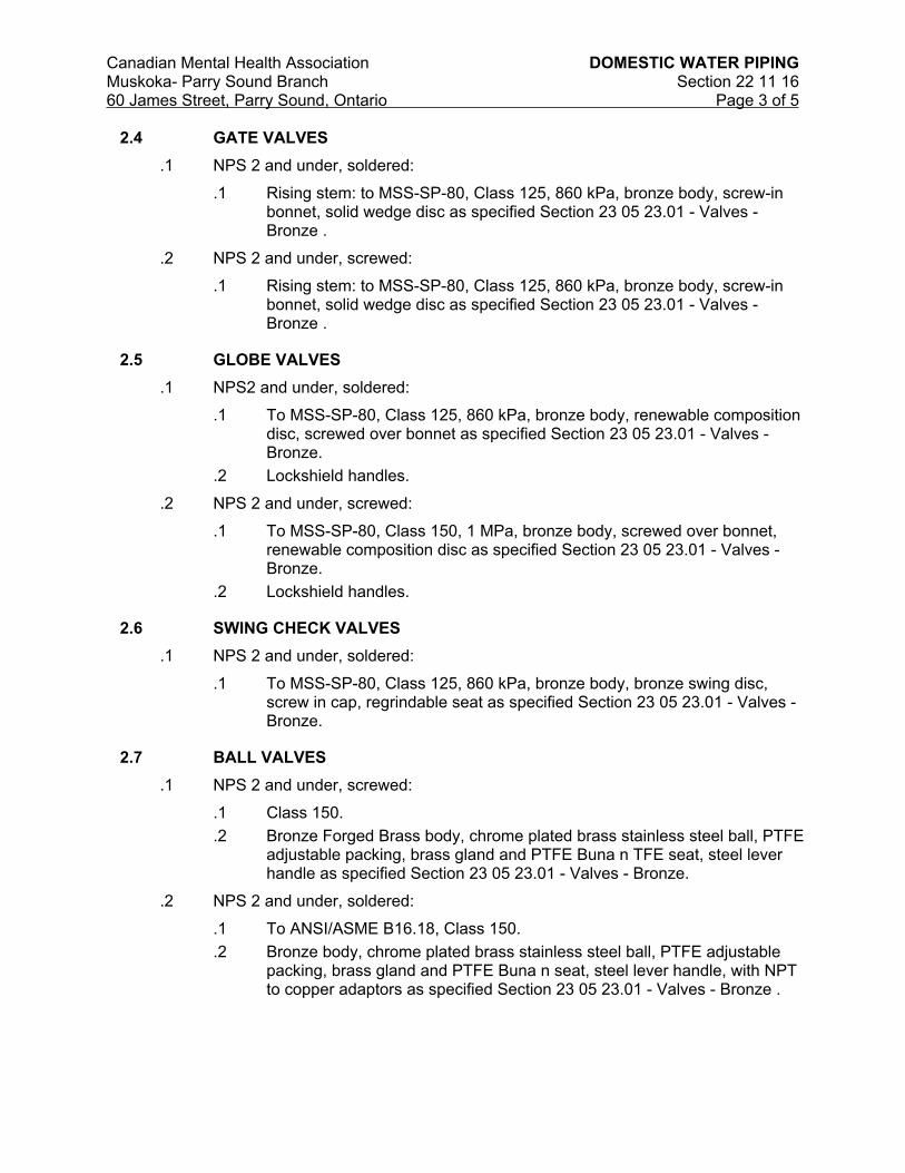
Canadian Mental Health Association DOMESTIC WATER PIPING
Muskoka- Parry Sound Branch Section 22 11 1660 James Street, Parry Sound, Ontario Page 3 of 5
2.4 GATE VALVES
.1 NPS 2 and under, soldered:
.1 Rising stem: to MSS-SP-80, Class 125, 860 kPa, bronze body, screw-in bonnet, solid wedge disc as specified Section 23 05 23.01 - Valves - Bronze .
.2 NPS 2 and under, screwed:
.1 Rising stem: to MSS-SP-80, Class 125, 860 kPa, bronze body, screw-in bonnet, solid wedge disc as specified Section 23 05 23.01 - Valves - Bronze .
2.5 GLOBE VALVES
.1 NPS2 and under, soldered:
.1 To MSS-SP-80, Class 125, 860 kPa, bronze body, renewable composition disc, screwed over bonnet as specified Section 23 05 23.01 - Valves - Bronze.
.2 Lockshield handles.
.2 NPS 2 and under, screwed:
.1 To MSS-SP-80, Class 150, 1 MPa, bronze body, screwed over bonnet, renewable composition disc as specified Section 23 05 23.01 - Valves - Bronze.
.2 Lockshield handles.
2.6 SWING CHECK VALVES
.1 NPS 2 and under, soldered:
.1 To MSS-SP-80, Class 125, 860 kPa, bronze body, bronze swing disc, screw in cap, regrindable seat as specified Section 23 05 23.01 - Valves - Bronze.
2.7 BALL VALVES
.1 NPS 2 and under, screwed:
.1 Class 150.
.2 Bronze Forged Brass body, chrome plated brass stainless steel ball, PTFE adjustable packing, brass gland and PTFE Buna n TFE seat, steel lever handle as specified Section 23 05 23.01 - Valves - Bronze.
.2 NPS 2 and under, soldered:
.1 To ANSI/ASME B16.18, Class 150.
.2 Bronze body, chrome plated brass stainless steel ball, PTFE adjustable packing, brass gland and PTFE Buna n seat, steel lever handle, with NPT to copper adaptors as specified Section 23 05 23.01 - Valves - Bronze .

Canadian Mental Health Association DOMESTIC WATER PIPING
Muskoka- Parry Sound Branch Section 22 11 1660 James Street, Parry Sound, Ontario Page 4 of 5
Part 3 EXECUTION
3.1 APPLICATION
.1 Manufacturer's Instructions: comply with manufacturer's written recommendations, including product technical bulletins, handling, storage and installation instructions, and datasheets.
3.2 INSTALLATION
.1 Install in accordance with Ontario Building Code and local authority having jurisdiction .
.2 Install pipe work in accordance with Section 23 05 05 - Installation of Pipework, supplemented as specified herein.
.3 Assemble piping using fittings manufactured to ANSI standards.
.4 Install DCW piping below and away from DHW, HWS and HWR and other hot piping so as to maintain temperature of cold water as low as possible.
.5 Connect to fixtures and equipment in accordance with manufacturer's written instructions unless otherwise indicated.
3.3 VALVES
.1 Isolate equipment, fixtures, washroom groups and branches with ball valves.
.2 Balance recirculation system using lock shield globe valves. Mark settings and record on as-built drawings on completion.
3.4 PRESSURE TESTS
.1 Conform to requirements of Section 21 05 01 - Common Work Results for Mechanical.
.2 Test pressure: greater of 1 times maximum system operating pressure or 860 kPa.
3.5 PRE-START-UP INSPECTIONS
.1 Systems to be complete, prior to flushing, testing and start-up.
.2 Verify that system can be completely drained.
.3 Ensure that air chambers, expansion compensators are installed properly.
3.6 START-UP
.1 Timing: start up after:
.1 Pressure tests have been completed.
.2 Disinfection procedures have been completed.
.3 Certificate of static completion has been issued.
.4 Water treatment systems operational.
.2 Provide continuous supervision during start-up.
.3 Start-up procedures:
.1 Establish circulation and ensure that air is eliminated.

Canadian Mental Health Association DOMESTIC WATER PIPING
Muskoka- Parry Sound Branch Section 22 11 1660 James Street, Parry Sound, Ontario Page 5 of 5
.2 Check pressurization to ensure proper operation and to prevent water hammer, flashing and/or cavitation.
.3 Check control, limit, safety devices for normal and safe operation.
.4 Rectify start-up deficiencies.
3.7 PERFORMANCE VERIFICATION
.1 Scheduling:
.1 Verify system performance after pressure and leakage tests and disinfection are completed, and Certificate of Completion has been issued by authority having jurisdiction.
.2 Procedures:
.1 Verify that flow rate and pressure meet Design Criteria.
.2 TAB HWC in accordance with Section 23 05 93 - Testing, Adjusting and Balancing for HVAC.
.3 Adjust pressure regulating valves while withdrawal is maximum and inlet pressure is minimum.
.4 Verify performance of temperature controls.
.5 Verify compliance with safety and health requirements.
.6 Check for proper operation of water hammer arrestors. Run one outlet for 10 seconds, then shut of water immediately. If water hammer occurs, replace water hammer arrestor or re-charge air chambers. Repeat for outlets and flush valves.
.7 Confirm water quality consistent with supply standards, and ensure no residuals remain as result of flushing or cleaning.
.3 Reports:
.1 Include certificate of water flow and pressure tests conducted on incoming water service, demonstrating adequacy of flow and pressure.
3.8 OPERATION REQUIREMENTS
.1 Co-ordinate operation and maintenance requirements including, cleaning and maintenance of specified materials and products with Section 23 05 05 - Installation of Pipework.
END OF SECTION

Canadian Mental Health Association DRAINAGE WASTE AND VENT PIPING
CAST IRON & COPPER
Muskoka- Parry Sound Branch Section 22 13 1760 James Street, Parry Sound, Ontario Page 1 of 3
PART 1 GENERAL
1.1 RELATED REQUIREMENTS
.1 Section 21 05 01 Common Work Results for Mechanical.
.2 Section 22 42 01 Plumbing Accessories.
1.2 REFERENCES
.1 ASTM International Inc.
.1 ASTM B32-08, Standard Specification for Solder Metal.
.2 ASTM B306-02, Standard Specification for Copper Drainage Tube (DWV).
.3 ASTM C564-03a, Standard Specification for Rubber Gaskets for Cast Iron Soil Pipe and Fittings.
.2 Canadian Standards Association (CSA International).
.1 CSA B67-1972(R1996), Lead Service Pipe, Waste Pipe, Traps, Bends and Accessories.
.2 CAN/CSA-B70-06, Cast Iron Soil Pipe, Fittings and Means of Joining.
.3 CAN/CSA-B125.3-05, Plumbing Fittings.
.3 Green Seal Environmental Standards (GSES)
.1 Standard GS-36-00, Commercial Adhesives.
1.3 ACTION AND INFORMATIONAL SUBMITTALS
.1 Provide submittals in accordance with Section 21 05 01 Common Work Results for Mechanical.
.2 Product Data:
.1 Provide manufacturer's printed product literature and datasheets for adhesives, and include product characteristics, performance criteria, physical size, finish and limitations.
1.4 DELIVERY, STORAGE AND HANDLING
.1 Deliver materials to site in original factory packaging, labelled with manufacturer's name, address.
.2 Packaging Waste Management: remove for reuse and return by manufacturer of pallets crates paddling and packaging materials.
1.5 SCOPE OF WORK
.1 Provide all cutting and patching for the work of this division.
.2 Provide drainage for all new fixtures and appliances, storm and sanitary systems.
.3 For drainage systems in unheated spaces provide heat tracing and insulation.

Canadian Mental Health Association DRAINAGE WASTE AND VENT PIPING
CAST IRON & COPPER
Muskoka- Parry Sound Branch Section 22 13 1760 James Street, Parry Sound, Ontario Page 2 of 3
PART 2 PRODUCTS
2.1 COPPER TUBE AND FITTINGS
.1 Above ground sanitary storm and vent Type DWV to: ASTM B306.
.1 Fittings.
.1 Cast brass: to CAN/CSA-B125.3.
.2 Wrought copper: to CAN/CSA-B125.3.
.2 Solder: tin-lead, 50:50, type 50A lead free, tin- 95:5, type TA , to ASTM B32.
2.2 CAST IRON PIPING AND FITTINGS
.1 Buried sanitary storm and vent minimum NPS 3 , to: CAN/CSA-B70, with one layer of protective coating of .
.1 Joints:
.1 Mechanical joints:
.1 Neoprene or butyl rubber compression gaskets: to ASTM C564 or CAN/CSA-B70.
.2 Stainless steel clamps.
.2 Hub and spigot:
.1 Caulking lead: to CSA B67.
.2 Cold caulking compounds.
.2 Above ground sanitary storm and vent : to CAN/CSA-B70.
.1 Joints:
.1 Hub and spigot:
.1 Caulking lead: to CSA B67.
.2 Mechanical joints:
.1 Neoprene or butyl rubber compression gaskets with stainless steel clamps.
PART 3 EXECUTION
3.1 APPLICATION
.1 Manufacturer's Instructions: comply with manufacturer's written recommendations, including product technical bulletins, handling, storage and installation instructions, and datasheets.
.2 Extend existing systems in similar materials where copper and cast are use as base building services.
3.2 INSTALLATION
.1 In accordance with Section 23 05 01 – Common Work Results for Mechanical.
.2 Install in accordance with Ontario Building Code and local authority having jurisdiction.

Canadian Mental Health Association DRAINAGE WASTE AND VENT PIPING
CAST IRON & COPPER
Muskoka- Parry Sound Branch Section 22 13 1760 James Street, Parry Sound, Ontario Page 3 of 3
.3 Provide access doors for all points in the system requiring access for maintenance.
3.3 TESTING
.1 Pressure test buried systems before backfilling.
.2 Hydraulically test to verify grades and freedom from obstructions.
3.4 PERFORMANCE VERIFICATION
.1 Cleanouts:
.1 Ensure accessible and that access doors are correctly located.
.2 Open, cover with linseed oil and re-seal.
.3 Verify that cleanout rods can probe as far as the next cleanout, at least.
.2 Test to ensure traps are fully and permanently primed.
.3 Storm water drainage:
.1 Verify domes are secure.
.2 Ensure weirs are correctly sized and installed correctly.
.3 Verify provisions for movement of roof system.
.4 Ensure that fixtures are properly anchored, connected to system and effectively vented.
.5 Affix applicable label (storm, sanitary, vent, pump discharge etc.) c/w directional arrows every floor or 4.5 m (whichever is less).
END OF SECTION

Canadian Mental Health Association DRAINAGE WASTE AND VENT PIPING –PLASTIC
Muskoka- Parry Sound Branch Section 22 13 1860 James Street, Parry Sound, Ontario Page 1 of 2
Part 1 General
1.1 RELATED REQUIREMENTS
.1 21 05 01 Common Work Results for Mechanical.
1.2 REFERENCES
.1 ASTM International Inc.
.1 ASTM D2564-04e1, Standard Specification for Solvent Cements for PVC Plastic Piping Systems.
.2 ASTM E84-15, (UL723) Standard Test Method for Surface Burning Characteristics of Building Materials
.2 Canadian Standards Association (CSA International), CAN/ULC
.1 CAN/CSA-Series B181.1, B181.2, B182.1, B182.2, B182.4 Thermoplastic Non pressure Pipe, Compendium - B1800 Series.
.2 CAN/ULC S102.2, FSC-25, SD-50
.3 Health Canada/Workplace Hazardous Materials Information System (WHMIS)
.1 Material Safety Data Sheets (MSDS).
1.3 ACTION AND INFORMATIONAL SUBMITTALS
.1 Provide submittals in accordance with 21 05 01 Common Work Results for Mechanical.
.2 Product Data:
.1 Provide manufacturer's printed product literature and datasheets for piping and adhesives, and include product characteristics, performance criteria, physical size, finish and limitations.
1.4 DELIVERY, STORAGE AND HANDLING
.1 Deliver materials to site in original factory packaging, labelled with manufacturer's name, address.
.2 Store at temperatures and conditions recommended by manufacturer.
Part 2 Products
2.1 MATERIAL
.1 Pipe & Fittings: for plenum rated applications IPEX PVC XFR or equal.
.2 Pipe & Fittings: for plenum rated applications IPEX PVC System 15 or XFR or equal.
.3 Adhesives and Sealants: In accordance with manufacturer’s recommendations. .
2.2 PIPING AND FITTINGS
.1 For buried and above ground DWV piping to:
.1 CAN/CSA B1800.

Canadian Mental Health Association DRAINAGE WASTE AND VENT PIPING –PLASTIC
Muskoka- Parry Sound Branch Section 22 13 1860 James Street, Parry Sound, Ontario Page 2 of 2
2.3 JOINTS
.1 Solvent weld for PVC: to ASTM D2564.
Part 3 Execution
3.1 APPLICATION
.1 Manufacturer's Instructions: comply with manufacturer's written recommendations, including product technical bulletins, handling, storage and installation instructions, and datasheets.
3.2 INSTALLATION
.1 In accordance with Section 23 05 05 - Installation of Pipework.
.2 Install in accordance with Ontario Building Code and local authority having jurisdiction.
3.3 TESTING
.1 Pressure test buried systems before backfilling.
.2 Hydraulically test to verify grades and freedom from obstructions.
3.4 PERFORMANCE VERIFICATION
.1 Cleanouts:
.1 Ensure accessible and that access doors are correctly located.
.2 Open, cover with linseed oil and re-seal.
.3 Verify cleanout rods can probe as far as the next cleanout, at least.
.2 Test to ensure traps are fully and permanently primed.
.3 Storm water drainage:
.1 Verify domes are secure.
.2 Ensure weirs are correctly sized and installed correctly.
.3 Verify provisions for movement of roof system.
.4 Ensure fixtures are properly anchored, connected to system and effectively vented.
.5 Affix applicable label (sanitary, vent, pump discharge) c/w directional arrows every floor or 4.5 m (whichever is less).
END OF SECTION

Canadian Mental Health Association PLUMBING SPECIALTIES AND ACCESSORIES
Muskoka- Parry Sound Branch Section 22 42 0160 James Street, Parry Sound, Ontario Page 1 of 5
Part 1 GENERAL
1.1 SUMMARY
.1 Section Includes:
.2 Materials and installation for plumbing specialties and accessories.
.3 Related Sections:
.4 Section 21 05 01 - Common Work Results for Mechanical
1.2 REFERENCES
.1 American Society for Testing and Materials International (ASTM).
.1 ASTM A126-95(2001), Specification for Gray Iron Castings for Valves, Flanges and Pipe Fittings.
.2 ASTM B62-02, Specification for Composition Bronze or Ounce Metal Castings.
.2 Canadian Standards Association (CSA International).
.1 CSA-B64 Series-01, Backflow Preventers and Vacuum Breakers.
.2 CSA-B79-94(R2000), Floor, Area and Shower Drains, and Cleanouts for Residential Construction.
.3 Plumbing and Drainage Institute (PDI).
.1 PDI-WH201-92, Water Hammer Arresters Standard.
1.3 SUBMITTALS
.1 Submittals in accordance with Section 21 05 01 Common Work Results for Mechanical.
.2 Product Data:
.1 Submit manufacturer's printed product literature, specifications and datasheet for fixtures and equipment.
.2 Indicate dimensions, construction details and materials for specified items.
.3 Shop Drawings:
.1 Submit shop drawings to indicate materials, finishes, method of anchorage, number of anchors, dimensions, construction and assembly details.
.2 Certificates: submit certificates signed by manufacturer certifying that materials comply with specified performance characteristics and physical properties.
.4 Instructions: submit manufacturer's installation instructions.
.5 Manufacturers' Field Reports: manufacturers' field reports specified.
.6 Closeout submittals: submit maintenance and engineering data for incorporation into manual specified in Section 21 05 01 Common Work Results for Mechanical, include:
.1 Description of plumbing specialties and accessories, giving manufacturers name, type, model, year and capacity.

Canadian Mental Health Association PLUMBING SPECIALTIES AND ACCESSORIES
Muskoka- Parry Sound Branch Section 22 42 0160 James Street, Parry Sound, Ontario Page 2 of 5
.2 Details of operation, servicing and maintenance.
.3 Recommended spare parts list.
1.4 QUALITY ASSURANCE
.1 Pre-Installation Meetings:
.2 Convene pre-installation meeting one week prior to beginning work of this Section and on-site installations.
.3 Verify project requirements.
.4 Review installation and substrate conditions.
.5 Co-ordination with other building sub-trades.
.6 Review manufacturer's installation instructions and warranty requirements.
1.5 DELIVERY, STORAGE AND HANDLING
.1 Waste Management and Disposal:
.2 Separate waste materials for reuse and recycling].
.3 Remove from site and dispose of packaging materials to appropriate recycling facilities.
Part 2 PRODUCTS
2.1 FLOOR DRAINS
.1 Floor Drains and Trench Drains: to CSA B79.
.1 Type 1: general duty; cast iron body round, adjustable head, nickel bronze strainer, integral seepage pan, and clamping collar.
2.2 CLEANOUTS
.1 Cleanout Plugs: heavy cast iron male ferrule with brass screws and threaded brass or bronze plug. Sealing-caulked lead seat or neoprene gasket.
.2 Access Covers:
.3 Wall Access: face or wall type, polished nickel bronze or stainless steel, square or round cover with flush head securing screws, bevelled edge frame complete with anchoring lugs.
.4 Floor Access: round cast iron body and frame with adjustable secured nickel bronze top and:
.5 Plugs: bolted bronze with neoprene gasket.
.6 Cover for Unfinished Concrete Floors: nickel bronze round or square, gasket, vandal-proof screws.
.7 Cover for Tile and Linoleum Floors: polished nickel bronze with recessed cover for linoleum or tile infill, complete with vandal-proof locking screws.
.8 Cover for Carpeted Floors: polished nickel bronze with deep flange cover for carpet infill, complete with carpet retainer vandal-proof locking screws.

Canadian Mental Health Association PLUMBING SPECIALTIES AND ACCESSORIES
Muskoka- Parry Sound Branch Section 22 42 0160 James Street, Parry Sound, Ontario Page 3 of 5
2.3 WATER HAMMER ARRESTORS
.1 Copper construction, bellows type: to PDI-WH201.
2.4 BACK FLOW PREVENTERS
.1 Preventers: to CSA-B64 Series, RP or DCVA for domestic water service connection to mechanical equipment.
.2 Double check valve assembly back flow preventer shall be complete with intermediate atmospheric vent or vacuum breaker.
2.5 VACUUM BREAKERS
.1 Breakers: to CSA-B64 Series, vacuum breaker atmospheric.
2.6 TRAP SEAL PRIMERS
.1 Brass, with integral vacuum breaker, NPS1/2 solder ends, NPS1/2 drip line connection.
Part 3 EXECUTION
3.1 MANUFACTURER'S INSTRUCTIONS
.1 Compliance: comply with manufacturer's written recommendations or specifications, including product technical bulletins, handling, storage and installation instructions, and data sheet.
3.2 INSTALLATION
.1 Install in accordance with Ontario Building Code and local authority having jurisdiction.
.2 Install in accordance with manufacturer's instructions and as specified.
3.3 CLEANOUTS
.1 Install cleanouts at base of soil and waste stacks, and rainwater leaders, at locations required code, and as indicated.
.2 Bring cleanouts to wall or finished floor unless serviceable from below floor.
.3 Building drain cleanout and stack base cleanouts: line size to maximum NPS4.
3.4 WATER HAMMER ARRESTORS
.1 Install on branch supplies to fixtures or group of fixtures where required.
3.5 BACK FLOW PREVENTORS
.1 Install in accordance with CSA-B64 Series, where indicated and elsewhere as required by code.
.2 Pipe discharge to terminate over nearest drain or service sink.

Canadian Mental Health Association PLUMBING SPECIALTIES AND ACCESSORIES
Muskoka- Parry Sound Branch Section 22 42 0160 James Street, Parry Sound, Ontario Page 4 of 5
3.6 BACKWATER VALVES
.1 Install in main sewer lines and at weeping tile connection in pit, elevator pit drain and at building cleanout.
3.7 TRAP SEAL PRIMERS
.1 Install for new floor drains.
.2 Install on cold water supply to nearest frequently used plumbing fixture, in concealed accessible space.
.3 Install plastic tubing to floor drain.
3.8 START-UP
.1 Timing: start-up only after:
.1 Pressure tests have been completed.
.2 Disinfection procedures have been completed.
.3 Certificate of static completion has been issued.
.4 Water treatment systems operational.
.2 Provide supervision during start-up.
3.9 TESTING AND ADJUSTING
.1 Timing:
.1 After start-up deficiencies rectified.
.2 After certificate of completion has been issued.
.3 Application tolerances:
.4 Pressure at fixtures: +/- 70 kPa.
.5 Flow rate at fixtures: +/- 20%.
.2 Adjustments:
.3 Verify that flow rate and pressure meet design criteria.
.4 Make adjustments while flow rate or withdrawal is (1) maximum and (2) 25% of maximum and while pressure is (1) maximum and (2) minimum.
.5 Floor drains:
.1 Verify operation of trap seal primer.
.2 Prime, using trap primer. Adjust flow rate to suit site conditions.
.3 Check operations of flushing features.
.4 Check security, accessibility, removability of strainer.
.5 Clean out baskets.
.6 Vacuum breakers, backflow preventers, backwater valves:
.1 Test tightness, accessibility for O&M of cover and of valve.

Canadian Mental Health Association PLUMBING SPECIALTIES AND ACCESSORIES
Muskoka- Parry Sound Branch Section 22 42 0160 James Street, Parry Sound, Ontario Page 5 of 5
.2 Simulate reverse flow and back-pressure conditions to test operation of vacuum breakers, backflow preventers.
.3 Verify visibility of discharge from open ports.
.7 Access doors:
.1 Verify size and location relative to items to be accessed.
.8 Cleanouts:
.1 Verify covers are gas-tight, secure, yet readily removable.
.9 Water hammer arrestors:
.1 Verify proper installation of correct type of water hammer arrester.
.10 Water make up assembly:
.1 Verify proper installation of water make up, valve settings, pressure.
END OF SECTION

Canadian Mental Health Association COMMERCIAL WASHROOM FIXTURES
Muskoka- Parry Sound Branch Section 22 42 0360 James Street, Parry Sound, Ontario Page 1 of 3
Part 1 GENERAL
1.1 RELATED REQUIREMENTS
.1 22 13 17 Drainage Waste Vent - Cast Iron & Copper.
.2 22 13 18 Drainage Waste Vent - Plastic
1.2 SUMMARY
.1 Provide connections to new plumbing fixtures complete with shut off valves for each item as indicated on the plans.
.2 Include disconnect, valve and cap existing fixtures to be removed as part of the demolition work for re-use.
.3 Do all cutting and patching for the foodservice division fixtures.
1.3 REFERENCES
.1 Canadian Standards Association (CSA International)
.1 CAN/CSA-B45 Series-02(R2008), Plumbing Fixtures.
.2 CAN/CSA-B125.3-05, Plumbing Fittings.
.3 CAN/CSA-B651-04, Accessible Design for the Built Environment.
1.4 ACTION AND INFORMATIONAL SUBMITTALS
.1 Provide submittals in accordance with Section 01 33 00 - Submittal Procedures.
.2 Product Data:
.1 Provide manufacturer's printed product literature and datasheets for washroom fixtures, and include product characteristics, performance criteria, physical size, finish and limitations.
.3 Indicate fixtures and trim:
.1 Dimensions, construction details, roughing-in dimensions.
.2 Factory-set water consumption per flush at recommended pressure.
.3 (For water closets, urinals): minimum pressure required for flushing.
.4 Shop Drawings:
.1 Provide drawings pre-checked stamped and signed by the General Contractor and the mechanical Contractor.
1.5 CLOSEOUT SUBMITTALS
.1 Provide operation and maintenance data for washroom fixtures, for incorporation into manual specified in Section 01 70 00 – Contract Closeout.
.2 Include:
.1 Description of fixtures and trim, giving manufacturer's name, type, model, year, capacity.
.2 Details of operation, servicing, maintenance.
.3 List of recommended spare parts.

Canadian Mental Health Association COMMERCIAL WASHROOM FIXTURES
Muskoka- Parry Sound Branch Section 22 42 0360 James Street, Parry Sound, Ontario Page 2 of 3
1.6 DELIVERY, STORAGE AND HANDLING
.1 Deliver materials to site in original factory packaging, labelled with manufacturer's name, address.
.2 Packaging Waste Management: remove for reuse and return by manufacturer of pallets crates paddling and packaging materials.
Part 2 PRODUCTS
2.1 MANUFACTURED UNITS
.1 Fixtures: manufacture in accordance with CAN/CSA-B45 series.
.2 Trim, fittings: manufacture in accordance with CAN/CSA-B125.3.
.3 Exposed plumbing brass to be chrome plated.
.4 Number, locations: as indicated on the plumbing plans M300, M301. .
.5 Fixtures in any one location to be product of one manufacturer and of same type.
.6 Trim in any one location to be product of one manufacturer and of same type.
.7 Washroom Fixtures:
.1 L-1, L-2, S-1, W-1, W-2, Refer to plumbing fixture schedule M100.
.8 Washroom Lavatory Trim:
.1 L-1, L-2, S-1 fixture locations.
.1 Chrome plated faucets, lead free brass construction.
.2 Open grid drain.
.3 Refer to architects plans & specifications for wall backing.
Part 3 EXECUTION
3.1 APPLICATION
.1 Manufacturer's Instructions: comply with manufacturer's written recommendations, including product technical bulletins, handling, storage and installation instructions, and datasheets.
3.2 INSTALLATION
.1 Mounting heights:
.1 Standard: to manufacturer's recommendations, measured from finished floor.
.2 Wall-hung fixtures: measured from finished floor.
.3 Barrier free: to most stringent CAN/CSA B651 .
3.3 ADJUSTING
.1 Conform to water conservation requirements specified this section.
.2 Adjustments:
.1 Adjust water flow rate to design flow rates.

Canadian Mental Health Association COMMERCIAL WASHROOM FIXTURES
Muskoka- Parry Sound Branch Section 22 42 0360 James Street, Parry Sound, Ontario Page 3 of 3
.2 Adjust pressure to fixtures to ensure no splashing at maximum pressures.
.3 Checks:
.1 Water closets, urinals: flushing action.
.2 Aerators: operation, cleanliness.
.3 Vacuum breakers, backflow preventers: operation under all conditions.
.4 Thermostatic controls:
.1 Verify temperature settings, operation of control, limit and safety controls.
3.4 CLEANING
.1 Remove surplus materials, excess materials, rubbish, tools and equipment.
.2 Waste Management: separate waste materials for reuse and recycling.
END OF SECTION

Canadian Mental Health Association USE OF MECHANICAL SYSTEMS DURING CONSTRUCTION
Muskoka – Parry Sound Section 23 05 0160 James Street, Parry Sound, Ontario Page 1 of 1
PART 1 GENERAL
1.1 SUMMARY
.1 Section Includes:
.1 Use of mechanical systems during construction.
1.2 USE OF SYSTEMS
.1 Use of new permanent heating and ventilating systems for supplying temporary heat or ventilation is permitted only under following conditions:.
.1 Entire system is complete, pressure tested, cleaned, flushed out.
.2 Building has been closed in, areas to be heated/ventilated are clean and will not thereafter be subjected to dust-producing processes.
.3 Portable heating and cooling systems have been removed from the area.
.4 There is no possibility of damage.
.5 Supply ventilation systems are protected by 60% filters, inspected daily, changed every week or more frequently as required.
.6 Return systems have approved filters over openings, inlets, outlets.
.7 Systems will be:
.1 Operated as per manufacturer's recommendations and instructions.
.2 Operated by Contractor.
.3 Monitored continuously by Contractor.
.8 Warranties and guarantees are not relaxed.
.9 Regular preventive and other manufacturers recommended maintenance routines are performed by Contractor at own expense and under supervision of the Consultant .
.10 Refurbish entire system before static completion; clean internally and externally, restore to "as- new" condition, replace filters in air systems.
.2 Filters specified in this Section are over and above those specified in other Sections of this project.
.3 Exhaust systems are not included in approvals for temporary ventilation.
PART 2 PRODUCTS
2.1 NOT USED.
PART 3 EXECUTION
3.1 NOT USED.
END OF SECTION

Canadian Mental Health Association INSTALLATION OF PIPEWORK
Muskoka – Parry Sound Section 23 05 0560 James Street, Parry Sound, Ontario Page 1 of 4
Part 1 GENERAL
1.1 RELATED REQUIREMENTS
.1 23 11 23 Facility Natural Gas Piping
.2 21 13 13 Wet Pipe Sprinkler Systems
.3 21 13 14 Stand Pipe and Hose Systems
1.2 REFERENCES
.1 Canadian General Standards Board (CGSB)
.1 CAN/CGSB-1.181-[99], Ready-Mixed Organic Zinc-Rich Coating.
.2 Ontario Fire Code (OFC 2007)
1.3 ACTION AND INFORMATIONAL SUBMITTALS
.1 Provide submittals in accordance with Section 21 05 01 Common Work Results for Mechanical.
.2 Product Data:
.1 Provide manufacturer's printed product literature, specifications and datasheets for piping and equipment and include product characteristics, performance criteria, physical size, finish and limitations.
1.4 DELIVERY, STORAGE AND HANDLING
.1 Deliver, store and handle materials in accordance with manufacturer's written instructions.
.2 Delivery and Acceptance Requirements:
.1 Deliver materials to site in original factory packaging, labelled with manufacturer's name, address.
.3 Packaging Waste Management: remove for re-use, recycling.
Part 2 Products
2.1 MATERIAL
.1 Paint: zinc-rich to CAN/CGSB-1.181.
.1 Primers, Paints, in accordance with manufacturer's recommendations for surface conditions.
.2 Sealants: in accordance with Section 07 92 00 -Sealants.
.3 Fire Stopping: in accordance with Section 07 85 00 - Fire Stopping.
Part 3 Execution
3.1 APPLICATION
.1 Manufacturer's Instructions: comply with manufacturer's written recommendations, including product technical bulletins, handling, storage, installation instructions, and datasheets.

Canadian Mental Health Association INSTALLATION OF PIPEWORK
Muskoka – Parry Sound Section 23 05 0560 James Street, Parry Sound, Ontario Page 2 of 4
3.2 CONNECTIONS TO EQUIPMENT
.1 In accordance with manufacturer's instructions unless otherwise indicated.
.2 Use valves and either unions or flanges for isolation and ease of maintenance and assembly.
.3 Use double swing joints when equipment mounted on vibration isolation and when piping subject to movement.
3.3 CLEARANCES
.1 Provide clearance around systems, equipment and components for observation of operation, inspection, servicing, maintenance and as recommended by manufacturer and Ontario Fire Code.
.2 Provide space for disassembly, removal of equipment and components as recommended by manufacturer, without interrupting operation of other system, equipment, components.
3.4 DRAINS
.1 Install piping with grade in direction of flow except as indicated.
.2 Install drain valve at low points in piping systems, at equipment and at section isolating valves.
.3 Pipe each drain valve discharge separately to above floor drain.
.1 Discharge to be visible.
.4 Drain valves: NPS 3/4 gate or globe valves unless indicated otherwise, with hose end male thread, cap and chain.
3.5 AIR VENTS
.1 Install automatic air vents to at high points in piping systems.
.2 Install isolating valve at each automatic air valve.
.3 Install drain piping to approved location and terminate where discharge is visible.
3.6 DIELECTRIC COUPLINGS
.1 General: compatible with system, to suit pressure rating of system.
.2 Locations: where dissimilar metals are joined.
.3 NPS 2 and under: isolating unions or bronze valves.
.4 Over NPS 2: isolating flanges.
3.7 PIPEWORK INSTALLATION
.1 Install pipework to CSA B139.
.2 Screwed fittings jointed with Teflon tape.
.3 Protect openings against entry of foreign material.
.4 Install to isolate equipment and allow removal without interrupting operation of other equipment or systems.
.5 Assemble piping using fittings manufactured to ANSI standards.
.6 Saddle type branch fittings may be used on mains if branch line is no larger than half size of main.
.1 Hole saw (or drill) and ream main to maintain full inside diameter of branch line prior to welding saddle.

Canadian Mental Health Association INSTALLATION OF PIPEWORK
Muskoka – Parry Sound Section 23 05 0560 James Street, Parry Sound, Ontario Page 3 of 4
.7 Install exposed piping, equipment, rectangular cleanouts and similar items parallel or perpendicular to building lines.
.8 Install concealed pipework to minimize furring space, maximize headroom, and conserve space.
.9 Slope piping, except where indicated, in direction of flow for positive drainage and venting.
.10 Install, except where indicated, to permit separate thermal insulation of each pipe.
.11 Group piping wherever possible.
.12 Ream pipes, remove scale and other foreign material before assembly.
.13 Use eccentric reducers at pipe size changes to ensure positive drainage and venting.
.14 Provide for thermal expansion as indicated.
.15 Valves:
.1 Install in accessible locations.
.2 Remove interior parts before soldering.
.3 Install with stems above horizontal position unless indicated.
.4 Valves accessible for maintenance without removing adjacent piping.
.5 Install globe valves in bypass around control valves.
.6 Use ball valves at branch take-offs for isolating purposes except where specified.
.16 Check Valves:
.1 Install silent check valves on discharge of pumps.
3.8 SLEEVES
.1 General: install where pipes pass through masonry, concrete structures, fire rated assemblies, and as indicated.
.2 Material: schedule 40 black steel pipe.
.3 Construction: use annular fins continuously welded at mid-point at foundation walls and where sleeves extend above finished floors.
.4 Sizes: 6 mm minimum clearance between sleeve and uninsulated pipe or between sleeve and insulation.
.5 Installation:
.1 Concrete, masonry walls, concrete floors on grade: terminate flush with finished surface.
.2 Other floors: terminate 25 mm above finished floor.
.3 Before installation, paint exposed exterior surfaces with heavy application of zinc-rich paint to CAN/CGSB-1.181.
.6 Sealing:
.1 Foundation walls and below grade floors: fire retardant, waterproof non-hardening mastic.
.2 Elsewhere:
.1 Provide space for fire-stopping.
.2 Maintain fire rating integrity.
.3 Sleeves installed for future use: fill with lime plaster or other easily removable filler.
.4 Ensure no contact between copper pipe or tube and sleeve.

Canadian Mental Health Association INSTALLATION OF PIPEWORK
Muskoka – Parry Sound Section 23 05 0560 James Street, Parry Sound, Ontario Page 4 of 4
3.9 ESCUTCHEONS
.1 Install on pipes passing through walls, partitions, floors, and ceilings in finished areas.
.2 Construction: one piece type with set screws.
.1 Chrome or nickel plated brass or type 302 stainless steel..
.3 Sizes: outside diameter to cover opening or sleeve.
.1 Inside diameter to fit around pipe or outside of insulation if so provided.
3.10 PREPARATION FOR FIRE STOPPING
.1 Install fire-stopping within annular space between pipes, ducts, insulation and adjacent fire separation in accordance with Section 07 85 00 - Fire Stopping.
.2 Insulated pipes and ducts: ensure integrity of insulation and vapour barriers.
3.11 FLUSHING OUT OF PIPING SYSTEMS
.1 Before start-up, clean interior of piping systems in accordance with requirements of Section 01 74 00 - Cleaning supplemented as specified in relevant mechanical sections.
.2 Preparatory to acceptance, clean and refurbish equipment and leave in operating condition, including replacement of filters in piping systems.
3.12 PRESSURE TESTING OF EQUIPMENT AND PIPEWORK
.1 Advise Consultant 48 hours minimum prior to performance of pressure tests.
.2 Pipework: test as specified in relevant sections of heating, ventilating and air conditioning work.
.3 Maintain specified test pressure without loss for 4 hours minimum unless specified for longer period of time in relevant mechanical sections.
.4 Prior to tests, isolate equipment and other parts which are not designed to withstand test pressure or media.
.5 Pay costs for repairs or replacement, retesting, and making good.
.6 Insulate or conceal work only after approval and certification of tests by Consultant.
3.13 EXISTING SYSTEMS
.1 Connect into existing piping systems at times approved by the owner.
.2 Request written approval by Consultant 10 days minimum, prior to commencement of work.
.3 Be responsible for damage to existing plant by this work.
3.14 CLEANING
.1 Clean in accordance with Section 01 74 00 - Cleaning.
.1 Remove surplus materials, excess materials, rubbish, tools and equipment.
.2 Waste Management: separate waste materials for reuse, recycling.
END OF SECTION
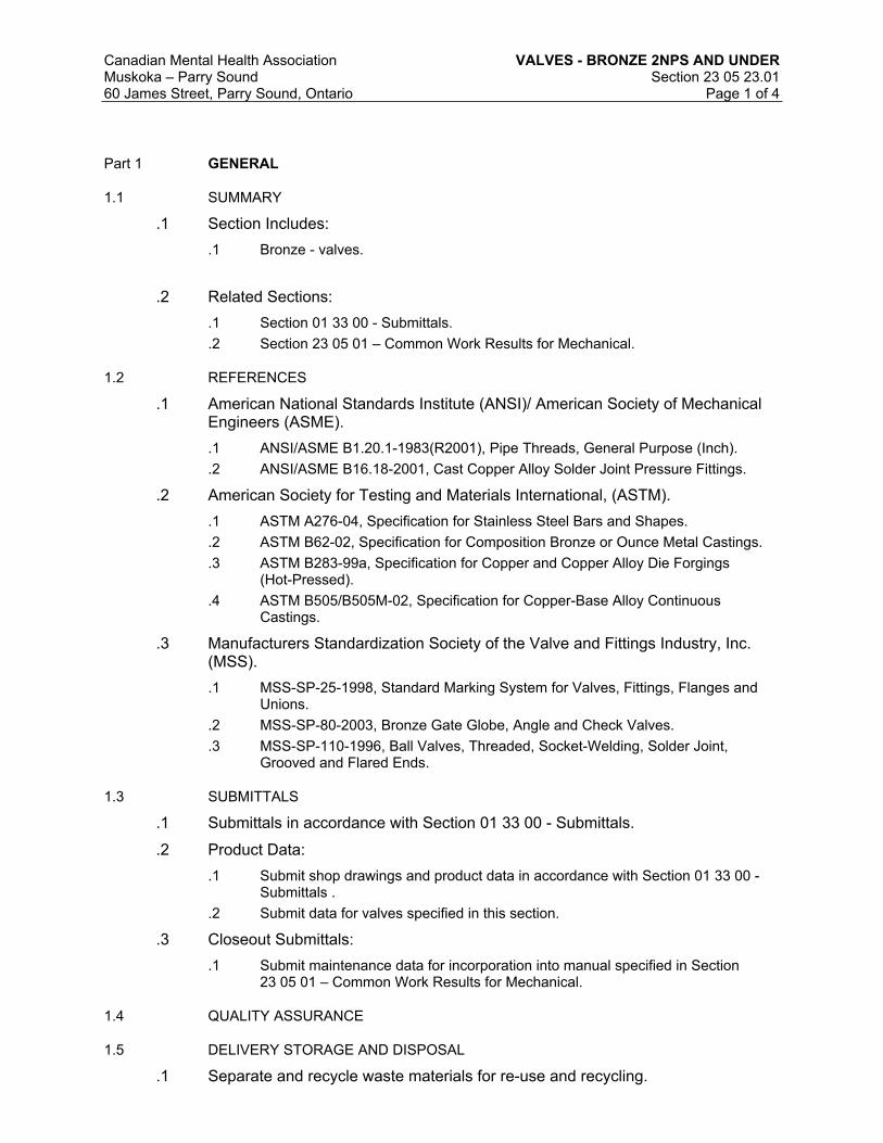
Canadian Mental Health Association VALVES - BRONZE 2NPS AND UNDER
Muskoka – Parry Sound Section 23 05 23.0160 James Street, Parry Sound, Ontario Page 1 of 4
Part 1 GENERAL
1.1 SUMMARY
.1 Section Includes:
.1 Bronze - valves.
.2 Related Sections:
.1 Section 01 33 00 - Submittals.
.2 Section 23 05 01 – Common Work Results for Mechanical.
1.2 REFERENCES
.1 American National Standards Institute (ANSI)/ American Society of Mechanical Engineers (ASME).
.1 ANSI/ASME B1.20.1-1983(R2001), Pipe Threads, General Purpose (Inch).
.2 ANSI/ASME B16.18-2001, Cast Copper Alloy Solder Joint Pressure Fittings.
.2 American Society for Testing and Materials International, (ASTM).
.1 ASTM A276-04, Specification for Stainless Steel Bars and Shapes.
.2 ASTM B62-02, Specification for Composition Bronze or Ounce Metal Castings.
.3 ASTM B283-99a, Specification for Copper and Copper Alloy Die Forgings (Hot-Pressed).
.4 ASTM B505/B505M-02, Specification for Copper-Base Alloy Continuous Castings.
.3 Manufacturers Standardization Society of the Valve and Fittings Industry, Inc. (MSS).
.1 MSS-SP-25-1998, Standard Marking System for Valves, Fittings, Flanges and Unions.
.2 MSS-SP-80-2003, Bronze Gate Globe, Angle and Check Valves.
.3 MSS-SP-110-1996, Ball Valves, Threaded, Socket-Welding, Solder Joint, Grooved and Flared Ends.
1.3 SUBMITTALS
.1 Submittals in accordance with Section 01 33 00 - Submittals.
.2 Product Data:
.1 Submit shop drawings and product data in accordance with Section 01 33 00 - Submittals .
.2 Submit data for valves specified in this section.
.3 Closeout Submittals:
.1 Submit maintenance data for incorporation into manual specified in Section 23 05 01 – Common Work Results for Mechanical.
1.4 QUALITY ASSURANCE
1.5 DELIVERY STORAGE AND DISPOSAL
.1 Separate and recycle waste materials for re-use and recycling.

Canadian Mental Health Association VALVES - BRONZE 2NPS AND UNDER
Muskoka – Parry Sound Section 23 05 23.0160 James Street, Parry Sound, Ontario Page 2 of 4
1.6 MAINTENANCE
.1 Extra Materials:
.2 Furnish following spare parts:
.1 Valve seats: one for every 10 valves each size, minimum 1 .
.2 Discs: one for every 10 valves, each size. Minimum 1 .
.3 Stem packing: one for every 10 valves, each size. Minimum 1 .
.4 Valve handles: 2 of each size.
.5 Gaskets for flanges: one for every 10 flanged joints.
Part 2 PRODUCTS
2.1 MATERIALS
.1 Valves:
.1 Except for specialty valves, to be single manufacturer.
.2 All products to have CRN registration numbers.
.2 End Connections:
.1 Connection into adjacent piping/tubing:
.1 Steel pipe systems: Screwed ends to ANSI/ASME B1.20.1.
.2 Copper tube systems: Solder ends to ANSI/ASME B16.18.
.3 Lockshield Keys:
.1 Where lock shield valves are specified, provide 10 keys of each size: malleable iron cadmium plated.
.4 Gate Valves:
.1 Requirements common to gate valves, unless specified otherwise:
.1 Standard specification: MSS SP-80.
.2 Bonnet: union with hexagonal shoulders.
.3 Connections: screwed with hexagonal shoulders.
.4 Inspection and pressure testing: to MSS SP-80. Tests to be hydrostatic.
.5 Packing: non-asbestos.
.6 Handwheel: non-ferrous.
.7 Handwheel Nut: bronze to ASTM B62.
.2 NPS 2 and under, rising stem, solid wedge disc, Class 125:
.1 Body: with long disc guides, screwed bonnet.
.2 Operator: Handwheel .
.5 Globe Valves:
.1 Requirements common to globe valves, unless specified otherwise:
.1 Standard specification: MSS SP-80.
.2 Bonnet: union with hexagonal shoulders.
.3 Connections: screwed with hexagonal shoulders.
.4 Pressure testing: to MSS SP-80. Tests to be hydrostatic.
.5 Stuffing box: threaded to bonnet with gland follower, packing nut, high grade non-asbestos packing.
.6 Handwheel: non-ferrous.
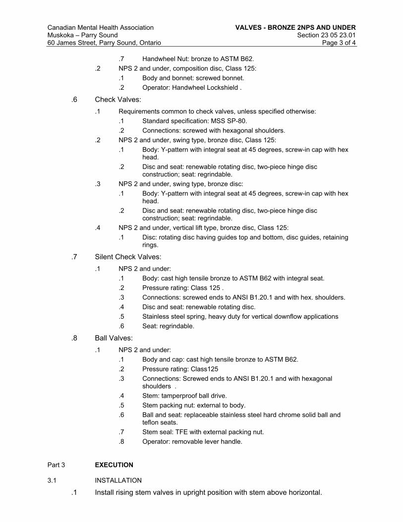
Canadian Mental Health Association VALVES - BRONZE 2NPS AND UNDER
Muskoka – Parry Sound Section 23 05 23.0160 James Street, Parry Sound, Ontario Page 3 of 4
.7 Handwheel Nut: bronze to ASTM B62.
.2 NPS 2 and under, composition disc, Class 125:
.1 Body and bonnet: screwed bonnet.
.2 Operator: Handwheel Lockshield .
.6 Check Valves:
.1 Requirements common to check valves, unless specified otherwise:
.1 Standard specification: MSS SP-80.
.2 Connections: screwed with hexagonal shoulders.
.2 NPS 2 and under, swing type, bronze disc, Class 125:
.1 Body: Y-pattern with integral seat at 45 degrees, screw-in cap with hex head.
.2 Disc and seat: renewable rotating disc, two-piece hinge disc construction; seat: regrindable.
.3 NPS 2 and under, swing type, bronze disc:
.1 Body: Y-pattern with integral seat at 45 degrees, screw-in cap with hex head.
.2 Disc and seat: renewable rotating disc, two-piece hinge disc construction; seat: regrindable.
.4 NPS 2 and under, vertical lift type, bronze disc, Class 125:
.1 Disc: rotating disc having guides top and bottom, disc guides, retaining rings.
.7 Silent Check Valves:
.1 NPS 2 and under:
.1 Body: cast high tensile bronze to ASTM B62 with integral seat.
.2 Pressure rating: Class 125 .
.3 Connections: screwed ends to ANSI B1.20.1 and with hex. shoulders.
.4 Disc and seat: renewable rotating disc.
.5 Stainless steel spring, heavy duty for vertical downflow applications
.6 Seat: regrindable.
.8 Ball Valves:
.1 NPS 2 and under:
.1 Body and cap: cast high tensile bronze to ASTM B62.
.2 Pressure rating: Class125
.3 Connections: Screwed ends to ANSI B1.20.1 and with hexagonal shoulders .
.4 Stem: tamperproof ball drive.
.5 Stem packing nut: external to body.
.6 Ball and seat: replaceable stainless steel hard chrome solid ball and teflon seats.
.7 Stem seal: TFE with external packing nut.
.8 Operator: removable lever handle.
Part 3 EXECUTION
3.1 INSTALLATION
.1 Install rising stem valves in upright position with stem above horizontal.

Canadian Mental Health Association VALVES - BRONZE 2NPS AND UNDER
Muskoka – Parry Sound Section 23 05 23.0160 James Street, Parry Sound, Ontario Page 4 of 4
.2 Remove internal parts before soldering.
.3 Install valves with unions at each piece of equipment arranged to allow servicing, maintenance, and equipment removal.
END OF SECTION

Canadian Mental Health Association BRONZE VALVES
Muskoka – Parry Sound Section 23 05 23.0560 James Street, Parry Sound, Ontario Page 1 of 4
PART 1 GENERAL
1.1 REFERENCES
.1 American National Standards Institute (ANSI)/American Society of Mechanical Engineers (ASME)
.1 ASME B1.20.1-1983(R2006), Pipe Threads, General Purpose (Inch).
.2 ASME B16.1-05, Gray Iron Pipe Flanges and Flanged Fittings: Classes 25,125 and 250.
.3 ANSI/ASME B16.5-03, Pipe Flanges and Flanged Fittings: NPS 1/2 through 24.
.4 ANSI/ASME B16.11-05, Forged Fittings, Socket-Welding and Threaded.
.5 ANSI/ASME B16.34-04, Valves - Flanged, Threaded and Welding Ends.
.2 ASTM International Inc.
.1 ASTM A126-04), Standard Specification for Gray Iron Castings for Valves, Flanges, and Pipe Fittings.
.2 ASTM A536-84(2004)e1, Standard Specification for Ductile Iron Castings.
.3 ASTM B62-02, Standard Specification for Composition Bronze or Ounce Metal Castings.
.4 ASTM B209M-07, Standard Specification for Aluminum and Aluminum-Alloy Sheet and Plate Metric.
.3 Manufacturers Standardization Society of the Valve and Fittings Industry, Inc. (MSS)
.1 MSS SP-67-02a, Butterfly Valves.
1.2 ACTION AND INFORMATIONAL SUBMITTALS
.1 Provide submittals in accordance with Section 21 05 01 Common Work Results for Mechanical.
.2 Product Data:
.1 Submit manufacturer's printed product literature, specifications and datasheets for valves and include product characteristics, performance criteria, physical size, finish and limitations.
.2 Submit data for valves specified in this section.
.3 Shop Drawings:
.1 Provide drawings pre-checked, stamped and signed by the General Contractor and the Mechanical Contractor
1.3 CLOSEOUT SUBMITTALS
.1 Submit maintenance data for incorporation into manual.
1.4 DELIVERY, STORAGE AND HANDLING
.1 Delivery and Acceptance Requirements:
.1 Deliver materials to site in original factory packaging, labelled with manufacturer's name, address.
1.5 MAINTENANCE MATERIAL SUBMITTALS
.1 Extra Materials/Spare Parts:
.2 Furnish following spare parts:

Canadian Mental Health Association BRONZE VALVES
Muskoka – Parry Sound Section 23 05 23.0560 James Street, Parry Sound, Ontario Page 2 of 4
.1 Valve seats: one for every 10 valves each size, minimum 1 .
.2 Discs: one for every 10 valves, each size, minimum 1 .
.3 Stem packing: one for every 10 valves, each size, minimum 1 .
.4 Valve handles: 2 of each size.
.5 Gaskets for flanges: one for every 10 flanged joints.
.3 Tools:
.1 Furnish special tools for maintenance of systems and equipment.
.2 Include following:
.1 Lubricant gun for expansion joints.
PART 2 PRODUCTS
2.1 MATERIAL
2.2 BUTTERFLY VALVES - RESILIENT SEAT - 200 PSIG
.1 Except specialty valves, to be of single manufacturer.
.2 To be suitable for dead-end service.
.3 CRN registration number required for products.
.4 Sizes:
.1 Wafer type: NPS 2 to 30.
.2 Grooved end type: NPS 2 to 12.
.5 Pressure rating for tight shut-off at temperatures up to maximum for seat material.
.1 NPS 2 - 12: 200 psig.
.6 Minimum seat temperature ratings to 121 degrees C.
.7 Application: on-off operation.
.8 Full lug body (threaded) Grooved ends.
.9 Operators:
.1 NPS 2 - 6: handles capable of locking in any of ten (10) positions - 0 degrees to 90 degrees. Handle and release trigger - ductile iron. Return spring and hinge pin: carbon steel. Latch plate and mounting hardware: cadmium plated carbon steel. Standard coating: black lacquer.
.2 NPS 8 - 30: manual enclosed gear operator as specified elsewhere in this section.
.10 Designed to comply with MSS SP-67 and API 609.
.11 Compatible with ANSI Class 125/Class 150 flanges.
.12 Construction:
.1 Body: ductile iron, SS, aluminum, bronze.
.2 Disc: aluminum bronze .
.3 Seat: EPDM .
.4 Shaft: 316 stainless steel.
.5 Taper pin: 316 SS .
.6 Key: carbon steel .
.7 O-Ring: EPDM .

Canadian Mental Health Association BRONZE VALVES
Muskoka – Parry Sound Section 23 05 23.0560 James Street, Parry Sound, Ontario Page 3 of 4
.8 Bushings: Teflon .
2.3 MOUNTING FLANGES
.1 Class 125 cast iron to ANSI B16.1 or Class 150 steel to B16.5 pipe flanges.
2.4 ELECTRIC ACTUATORS
.1 Operation: designed to provide precise quarter turn electric operation.
.1 Torque range: up to 1.130 N-m and speed ranges from 10 seconds to 30 seconds to move from fully open to fully closed.
.2 Gear train within actuator to provide smooth continuous rotary power stroke for accurate automatic valve positioning. Factory-set, field adjustable cam-actuated travel limit switches to provide precise control of shaft rotation.
.2 Construction:
.1 Castings: heavy duty industrial grade for rugged use.
.2 Actuators: continuous duty with high efficiency single phase reversing capacitor motor with thermal overload protection.
.3 Gears and pinions constructed from hardened steel.
.4 Gear train to be permanently lubricated.
.5 Mechanical brake to ensure that gear is locked in precise position.
.3 Electrical:
.1 Standard voltage: 120 VAC. 60 Hz .
.2 Control options: 0-10 V DC.
.3 CSA approved.
.4 Electrical rating: NEMA IV.
PART 3 EXECUTION
3.1 PREPARATION
.1 Valve and mating flange preparation.
.1 Inspect adjacent pipeline, remove rust, scale, welding slag, other foreign material.
.2 Ensure that valve seats and pipe flange faces are free of dirt or surface irregularities which may disrupt flange seating and cause external leakage.
.3 Install butterfly valves with disc in almost closed position.
.4 Inspect valve disc seating surfaces and waterway and eliminate dirt or foreign material.
3.2 INSTALLATION OF VALVES
.1 Install in accordance with manufacturer's instructions.
.2 Do not use gaskets between pipe flanges and valves unless instructed otherwise by valve manufacturer.
.3 Verify suitability of valve for application by inspection of identification tag.
.4 Mount actuator on to valve prior to installation.
.5 Handle valve with care so as to prevent damage to disc and seat faces.
.6 Valves in horizontal pipe lines should be installed with stem in horizontal position to minimize liner and seal wear.

Canadian Mental Health Association BRONZE VALVES
Muskoka – Parry Sound Section 23 05 23.0560 James Street, Parry Sound, Ontario Page 4 of 4
.7 Ensure that valves are centered between bolts before bolts are tightened and then opened and closed to ensure unobstructed disc movement. If interference occurs due, for example to pipe wall thickness, taper bore adjacent piping to remove interference.
3.3 ACTUATOR INSTALLATION
.1 Electrical connections to be made by actuator manufacturer.
.2 Cycle valve operation from fully closed to fully open then back to fully closed.
.3 At same time, check travel stop settings for proper disc alignment.
3.4 CLEANING
.1 Clean in accordance with Section 01 74 11 - Cleaning .
.2 Clean installed products in accordance to manufacturer's recommendation.
END OF SECTION

Canadian Mental Health Association HANGERS AND SUPPORTS FOR HVAC
PIPING AND EQUIPMENT
Muskoka – Parry Sound Section 23 05 2960 James Street, Parry Sound, Ontario Page 1 of 6
PART 1 GENERAL
1.1 SUMMARY
.1 Section Includes:
.1 Concrete housekeeping pads, hangers and supports for mechanical piping, ducting and equipment.
.2 Related Sections:
.1 22 11 16 – Domestic Water Piping
1.2 REFERENCES
.1 American National Standards Institute/American Society of Mechanical Engineers (ANSI/ASME)
.2 ANSI/ASME B31.1-04, Power Piping.
.2 American Society for Testing and Materials International (ASTM)
.1 ASTM A125-1996(R2001), Specification for Steel Springs, Helical, Heat Treated.
.2 ASTM A307-04, Specification for Carbon Steel Bolts and Studs, 60,000 PSI Tensile Strength.
.3 ASTM A563-04a, Specification for Carbon and Alloy Steel Nuts.
.3 Factory Mutual (FM)
.4 Manufacturer's Standardization Society of the Valves and Fittings Industry (MSS)
.1 MSS SP58-2002, Pipe Hangers and Supports - Materials, Design and Manufacture.
.2 ANSI/MSS SP69-2003, Pipe Hangers and Supports - Selection and Application.
.3 MSS SP89-2003, Pipe Hangers and Supports - Fabrication and Installation Practices.
.5 Underwriters Laboratories of Canada (ULC)
1.3 SYSTEM DESCRIPTION
.1 Design Requirements:
.1 Construct pipe hanger and support to manufacturer's recommendations utilizing manufacturer's regular production components, parts and assemblies.
.2 Base maximum load ratings on allowable stresses prescribed by MSS SP58.ASME B31.1 or
.3 Ensure that supports, guides, anchors do not transmit excessive quantities of heat to building structure.
.4 Design hangers and supports to support systems under conditions of operation, allow free expansion and contraction, prevent excessive stresses from being introduced into pipe work or connected equipment.
.5 Provide for vertical adjustments after erection and during commissioning. Amount of adjustment in accordance with MSS SP58.
.2 Performance Requirements:
.1 Design supports, platforms, hangers, to withstand seismic events as required by the Ontario Building Code.
1.4 SUBMITTALS
.1 Submittals: in accordance with Section 21 05 01 Common Work Results for Mechanical.

Canadian Mental Health Association HANGERS AND SUPPORTS FOR HVAC
PIPING AND EQUIPMENT
Muskoka – Parry Sound Section 23 05 2960 James Street, Parry Sound, Ontario Page 2 of 6
.2 Shop drawings: submit drawings pre-checked and signed by the mechanical contractor and the Mechanical General Contractor.
.3 Submit shop drawings and product data for following items:
.1 Bases, hangers and supports.
.2 Connections to equipment and structure.
.3 Structural assemblies.
.4 Closeout Submittals:
.1 Provide maintenance data for incorporation into manual specified in 21 05 01 Common Work Results for Mechanical.
1.5 DELIVERY, STORAGE, AND HANDLING
.1 Packing, shipping, handling and unloading:
.1 Deliver, store and handle in accordance with Section 01 61 00 - Common Product Requirements.
.2 Deliver, store and handle materials in accordance with manufacturer's written instructions.
.2 Waste Management and Disposal:
.1 Construction/Demolition Waste Management and Disposal: separate waste materials for reuse and recycling.
PART 2 PRODUCTS
2.1 GENERAL
.1 Fabricate hangers, supports and sway braces in accordance with ANSI B31.1 and MSS SP58.
.2 Use components for intended design purpose only. Do not use for rigging or erection purposes.
2.2 PIPE HANGERS
.1 Finishes:
.1 Pipe hangers and supports: galvanized painted with zinc rich paint after manufacture.
.2 Use electroplating galvanizing process hot dipped galvanizing process.
.3 Ensure steel hangers in contact with copper piping are copper plated epoxy coated.
.2 Upper attachment structural: suspension from lower flange of I Beam:
.1 Cold piping NPS 2 maximum: malleable iron C clamp with hardened steel cup point setscrew, locknut and carbon steel retaining clip .
.1 Rod: 9 mm UL listed 13 mm FM approved.
.2 Cold piping NPS 2 1/2 or greater, hot piping: malleable iron beam clamp, eye rod, jaws and extension with carbon steel retaining clip, tie rod, nuts and washers, UL listed FM approved to MSS-SP58 and MSS-SP69 .
.3 Upper attachment structural: suspension from upper flange of I Beam:
.1 Cold piping NPS 2 maximum: ductile iron top of beam C clamp with hardened steel cup point setscrew, locknut and carbon steel retaining clip, UL listed FM approved to MSS SP69.

Canadian Mental Health Association HANGERS AND SUPPORTS FOR HVAC
PIPING AND EQUIPMENT
Muskoka – Parry Sound Section 23 05 2960 James Street, Parry Sound, Ontario Page 3 of 6
.2 Cold piping NPS 2 1/2 or greater, hot piping: malleable iron top of beam jaw clamp with hooked rod, spring washer, plain washer and nut UL listed FM approved.
.4 Upper attachment to concrete:
.1 Ceiling: carbon steel welded eye rod, clevis plate, clevis pin and cotters with weldless forged steel eye nut. Ensure eye 6 mm minimum greater than rod diameter.
.2 Concrete inserts: wedge shaped body with knockout protector plate UL listed FM approved to MSS SP69.
.5 Shop and field fabricated assemblies:
.1 Trapeze hanger assemblies: .
.2 Steel brackets: .
.3 Sway braces for seismic restraint.
.6 Hanger rods: threaded rod material to MSS SP58:
.1 Ensure that hanger rods are subject to tensile loading only.
.2 Provide linkages where lateral or axial movement of pipe work is anticipated.
.3 Do not use 22 mm or 28 mm rod.
.7 Pipe attachments: material to MSS SP58:
.1 Attachments for steel piping: carbon steel black.
.2 Attachments for copper piping: copper plated black steel.
.3 Use insulation shields for hot pipe work.
.4 Oversize pipe hangers and supports.
.8 Adjustable clevis: material to MSS SP69 UL listed FM approved, clevis bolt with nipple spacer and vertical adjustment nuts above and below clevis.
.1 Ensure "U" has hole in bottom for riveting to insulation shields .
.9 Yoke style pipe roll: carbon steel yoke, rod and nuts with cast iron roll, to MSS SP69.
.10 U bolts: carbon steel to MSS SP69 with 2 nuts at each end to ASTM A563.
.1 Finishes for steel pipe work: black .
.2 Finishes for copper, glass, brass or aluminum pipe work: black , with formed portion plastic coated epoxy coated.
.11 Pipe rollers: cast iron roll and roll stand with carbon steel rod to MSS SP69.
2.3 RISER CLAMPS
.1 Steel or cast iron pipe: black carbon steel to MSS SP58, type 42, UL listed FM approved.
.2 Copper pipe: carbon steel copper plated to MSS SP58, type 42.
.3 Bolts: to ASTM A307.
.4 Nuts: to ASTM A563.
2.4 INSULATION PROTECTION SHIELDS
.1 Insulated cold piping:
.1 64 kg/m3 density insulation plus insulation protection shield to: MSS SP69, galvanized sheet carbon steel. Length designed for maximum 3 m span.
.2 Insulated hot piping:
.1 Curved plate 300 mm long, with edges turned up, welded in centre plate for pipe sizes NPS 12 and over, carbon steel to comply with MSS SP69.

Canadian Mental Health Association HANGERS AND SUPPORTS FOR HVAC
PIPING AND EQUIPMENT
Muskoka – Parry Sound Section 23 05 2960 James Street, Parry Sound, Ontario Page 4 of 6
2.5 CONSTANT SUPPORT SPRING HANGERS
.1 Springs: alloy steel to ASTM A125, shot peened, magnetic particle inspected, with +/-5% spring rate tolerance, tested for free height, spring rate, loaded height and provided with Certified Mill Test Report (CMTR).
.2 Load adjustability: 10 % minimum adjustability each side of calibrated load. Adjustment without special tools. Adjustments not to affect travel capabilities.
.3 Provide upper and lower factory set travel stops.
.4 Provide load adjustment scale for field adjustments.
.5 Total travel to be actual travel + 20%. Difference between total travel and actual travel 25 mm minimum.
.6 Individually calibrated scales on each side of support calibrated prior to shipment, complete with calibration record.
2.6 VARIABLE SUPPORT SPRING HANGERS
.1 Vertical movement: 13 mm minimum, 50 mm maximum, use single spring pre-compressed variable spring hangers.
.2 Vertical movement greater than 50 mm: use double spring pre-compressed variable spring hanger with 2 springs in series in single casing.
.3 Variable spring hanger complete with factory calibrated travel stops. Provide certificate of calibration for each hanger .
.4 Steel alloy springs: to ASTM A125, shot peened, magnetic particle inspected, with +/-5 % spring rate tolerance, tested for free height, spring rate, loaded height and provided with CMTR.
2.7 EQUIPMENT SUPPORTS
.1 Fabricate equipment supports not provided by equipment manufacturer from structural grade steel. Submit calculations with shop drawings.
2.8 EQUIPMENT ANCHOR BOLTS AND TEMPLATES
.1 Provide templates to ensure accurate location of anchor bolts.
2.9 HOUSE-KEEPING PADS
.1 Provide 100 mm high concrete housekeeping pads for base-mounted equipment; size pads 50 mm larger than equipment; chamfer pad edges.
PART 3 EXECUTION
3.1 MANUFACTURER'S INSTRUCTIONS
.1 Compliance: comply with manufacturer's written recommendations or specifications, including product technical bulletins, handling, storage and installation instructions, and datasheet.
3.2 INSTALLATION
.1 Install in accordance with:
.1 manufacturer's instructions and recommendations.
.2 Vibration Control Devices:
.1 Install on piping systems at pumps, boilers, chillers, cooling towers, and as indicated.

Canadian Mental Health Association HANGERS AND SUPPORTS FOR HVAC
PIPING AND EQUIPMENT
Muskoka – Parry Sound Section 23 05 2960 James Street, Parry Sound, Ontario Page 5 of 6
.3 Clamps on riser piping:
.1 Support independent of connected horizontal pipe work using riser clamps and riser clamp lugs welded to riser.
.2 Bolt tightening torques to industry standards.
.3 Steel pipes: install below coupling or shear lugs welded to pipe.
.4 Cast iron pipes: install below joint.
.4 Clevis plates:
.1 Attach to concrete with 4 minimum concrete inserts, one at each corner.
.5 Provide supplementary structural steelwork where structural bearings do not exist or where concrete inserts are not in correct locations.
.6 Use approved constant support type hangers where:
.1 vertical movement of pipe work is 13 mm or more,
.2 transfer of load to adjacent hangers or connected equipment is not permitted.
.7 Use variable support spring hangers where:
.1 transfer of load to adjacent piping or to connected equipment is not critical.
.2 variation in supporting effect does not exceed 25 % of total load.
3.3 HANGER SPACING
.1 Plumbing piping: to Ontario Building Code .
.2 Fire protection: to applicable fire code.
.3 Gas and fuel oil piping: up to NPS 1/2: every 1.8 m.
.4 Copper piping: up to NPS 1/2: every 1.5 m.
.5 Flexible joint roll groove pipe: in accordance with table below, but not less than one hanger at joints.
.6 Within 300 mm of each elbow.
Maximum Pipe Size : NPS Maximum Spacing Steel Maximum Spacing Copperup to 1-1/4 2.1 m 1.8 m1-1/2 2.7 m 2.4 m2 3.0 m 2.7 m2-1/2 3.6 m 3.0 m3 3.6 m 3.0 m3-1/2 3.9 m 3.3 m4 4.2 m 3.6 m5 4.8 m6 5.1 m8 5.7 m10 6.6 m12 6.9 m
.7 Pipe work greater than NPS 12: to MSS SP69.
3.4 HANGER INSTALLATION
.1 Install hanger so that rod is vertical under operating conditions.
.2 Adjust hangers to equalize load.

Canadian Mental Health Association HANGERS AND SUPPORTS FOR HVAC
PIPING AND EQUIPMENT
Muskoka – Parry Sound Section 23 05 2960 James Street, Parry Sound, Ontario Page 6 of 6
.3 Support from structural members. Where structural bearing does not exist or inserts are not in suitable locations, provide supplementary structural steel members.
3.5 HORIZONTAL MOVEMENT
.1 Angularity of rod hanger resulting from horizontal movement of pipe work from cold to hot position not to exceed 4 degrees from vertical.
.2 Where horizontal pipe movement is less than 13 mm, offset pipe hanger and support so that rod hanger is vertical in the hot position.
3.6 FINAL ADJUSTMENT
.1 Adjust hangers and supports:
.1 Ensure that rod is vertical under operating conditions.
.2 Equalize loads.
.2 Adjustable clevis:
.1 Tighten hanger load nut securely to ensure proper hanger performance.
.2 Tighten upper nut after adjustment.
.3 C clamps:
.1 Follow manufacturer's recommended written instructions and torque values when tightening C clamps to bottom flange of beam.
.4 Beam clamps:
.1 Hammer jaw firmly against underside of beam.
.5 Manufacturer's Field Services:
.1 Provide manufacturer's field services consisting of product use recommendations and periodic site visits for inspection of product installation in accordance with manufacturer's instructions.
END OF SECTION

Canadian Mental Health Association VIBRATION ISOLATION
Muskoka – Parry Sound Section 23 05 4860 James Street, Parry Sound, Ontario Page 1 of 4
Part 1 GENERAL
1.1 SUMMARY
.1 Section Includes:
.1 Vibration isolation materials, components, seismic control.
.2 Related Sections:
.1 23 05 93 - Testing, Adjusting and Balancing for HVAC.
1.2 REFERENCES
.1 National Fire Protection Association (NFPA)
.1 NFPA 13-2010, Standard for the Installation of Sprinkler Systems.
.2 Ontario Building Code – 2012
1.3 SUBMITTALS
.1 Submittals: in accordance with Section 21 05 01 - Common Work Results for Mechanical.
.1 Submit manufacturer's printed product literature, specifications and datasheet in accordance with Section 21 05 01 - Common Work Results for Mechanical. Include product characteristics, performance criteria, and limitations.
.2 Submit shop drawings in accordance with Section 21 05 01 - Common Work Results for Mechanical.
.1 Shop drawings: submit drawings pre-checked and approved by the mechanical contractor and the general contractor.
.2 Provide separate shop drawings for each isolated system complete with performance and product data.
.3 Quality assurance submittals: submit following in accordance with Section 21 05 01 - Common Work Results for Mechanical.
.1 Certificates: submit certificates signed by manufacturer certifying that materials comply with specified performance characteristics and physical properties.
.2 Instructions: submit manufacturer's installation instructions.
1.4 DELIVERY, STORAGE, AND HANDLING
.1 Packing, shipping, handling and unloading:
.1 Deliver, store and handle materials in accordance with manufacturer's written instructions.
.2 Waste Management and Disposal:
.1 Construction/Demolition Waste Management and Disposal: separate waste materials for reuse and recycling.
Part 2 PRODUCTS
2.1 GENERAL
.1 Size and shape of bases type and performance of vibration isolation as indicated.

Canadian Mental Health Association VIBRATION ISOLATION
Muskoka – Parry Sound Section 23 05 4860 James Street, Parry Sound, Ontario Page 2 of 4
2.2 ELASTOMERIC PADS
.1 Type EP1 - neoprene waffle or ribbed; 9 mm minimum thick; 50 durometer; maximum loading 350 kPa.
.2 Type EP2 - rubber waffle or ribbed; 9 mm minimum thick; 30 durometer natural rubber; maximum loading 415 kPa.
.3 Type EP3 - neoprene-steel-neoprene; 9 mm minimum thick neoprene bonded to 1.71 mm steel plate; 50 durometer neoprene, waffle or ribbed; holes sleeved with isolation washers; maximum loading 350 kPa.
.4 Type EP4 - rubber-steel-rubber; 9 mm minimum thick rubber bonded to 1.71 mm steel plate; 30 durometer natural rubber, waffle or ribbed; holes sleeved with isolation washers; maximum loading 415 kPa.
2.3 ELASTOMERIC MOUNTS
.1 Type M1 - colour coded; neoprene in shear; maximum durometer of 60 ; threaded insert and two bolt down holes; ribbed top and bottom surfaces.
2.4 SPRINGS
.1 Design stable springs: ratio of lateral to axial stiffness is equal to or greater than 1.2 times ratio of static deflection to working height. Select for 50% travel beyond rated load. Units complete with levelling devices.
.2 Ratio of height when loaded to diameter of spring between 0.8 to 1.0.
.3 Cadmium plate for outdoor installations.
.4 Colour code springs.
2.5 SPRING MOUNT
.1 Zinc or cadmium plated hardware; housings coated with rust resistant paint.
.2 Type M2 - stable open spring: support on bonded 6 mm minimum thick ribbed neoprene or rubber friction and acoustic pad.
.3 Type M3 - stable open spring: 6 mm minimum thick ribbed neoprene or rubber friction and acoustic pad, bonded under isolator and on isolator top plate; levelling bolt for rigidly mounting to equipment.
.4 Type M4 - restrained stable open spring: supported on bonded 6 mm minimum thick ribbed neoprene or rubber friction and acoustic pad; built-in resilient limit stops, removable spacer plates.
.5 Type M5 - enclosed spring mounts with snubbers for isolation up to 950 kg maximum.
.6 Performance: as required for equipment supported in accordance with manufacturers recommendations.
2.6 HANGERS
.1 Colour coded springs, rust resistant, painted box type hangers. Arrange to permit hanger box or rod to move through a 30 degrees arc without metal to metal contact.
.2 Type H1 - neoprene - in-shear, moulded with rod isolation bushing which passes through hanger box.
.3 Type H2 - stable spring, elastomeric washer, cup with moulded isolation bushing which passes through hanger box.
.4 Type H3 - stable spring, elastomeric element, cup with moulded isolation bushing which passes through hanger box.

Canadian Mental Health Association VIBRATION ISOLATION
Muskoka – Parry Sound Section 23 05 4860 James Street, Parry Sound, Ontario Page 3 of 4
.5 Type H4 - stable spring, elastomeric element with pre-compression washer and nut with deflection indicator .
.6 Performance: as required for equipment supported in accordance with manufacturers recommendations.
2.7 ACOUSTIC BARRIERS FOR ANCHORS AND GUIDES
.1 Acoustic barriers: between pipe and support, consisting of 25 mm minimum thick heavy duty neoprene isolation material.
2.8 HORIZONTAL THRUST RESTRAINT
.1 Spring and elastomeric element housed in box frame; assembly complete with rods and angle brackets for equipment and ductwork attachment; provision for adjustment to limit maximum start and stop movement to 9 mm.
.2 Arrange restraints symmetrically on either side of unit and attach at centerline of thrust.
Part 3 EXECUTION
3.1 MANUFACTURER'S INSTRUCTIONS
.1 Compliance: comply with manufacturer's written recommendations or specifications, including product technical bulletins, handling, storage and installation instructions, and datasheet.
3.2 INSTALLATION
.1 Seismic control measures to meet requirements of OBC .
.2 Install vibration isolation equipment in accordance with manufacturer’s instructions and adjust mountings to level equipment.
.3 Ensure piping, ducting and electrical connections to isolated equipment do not reduce system flexibility and that piping, conduit and ducting passage through walls and floors do not transmit vibrations.
.4 Unless indicated otherwise, support piping connected to isolated equipment with spring mounts or spring hangers with 25 mm minimum static deflection as follows:
.1 Up to NPS4: first 3 points of support. NPS5 to NPS8: first 4 points of support. NPS10 and Over: first 6 points of support.
.2 First point of support: static deflection of twice deflection of isolated equipment, but not more than 50 mm.
.5 Where isolation is bolted to floor use vibration isolation rubber washers.
.6 Block and shim level bases so that ductwork and piping connections can be made to rigid system at operating level, before isolator adjustment is made. Ensure that there is no physical contact between isolated equipment and building structure.
3.3 FIELD QUALITY CONTROL
.1 Manufacturer's Field Services:
.1 Arrange with manufacturer's representative to review work of this Section and submit written reports to verify compliance with Contract Documents.
.2 Manufacturer's Field Services: consisting of product use recommendations and periodic site visits to review installation, scheduled as follows:
.1 Upon completion of installation.

Canadian Mental Health Association VIBRATION ISOLATION
Muskoka – Parry Sound Section 23 05 4860 James Street, Parry Sound, Ontario Page 4 of 4
.3 Submit manufacturer's reports to Consultant within 3 days of manufacturer representative's review.
.4 Make adjustments and corrections in accordance with written report.
.2 Inspection and Certification:
.1 Experienced and competent sound and vibration testing professional engineer to take vibration measurement for HVAC systems after start up and TAB of systems to Section 23 05 93 - Testing, Adjusting and Balancing for HVAC .
.2 Take vibration measurements for equipment as indicated listed below:
.1 Package Rooftop and Built up HVAC
.3 Provide Consultant with notice 24 h in advance of commencement of tests.
.4 Establish adequacy of equipment isolation and acceptability of noise levels in occupied areas and where appropriate, remedial recommendations (including sound curves).
.5 Submit complete report of test results including sound curves .
3.4 CLEANING
.1 Upon completion and verification of performance of installation, remove surplus materials, excess materials, rubbish, tools and equipment.
END OF SECTION

Canadian Mental Health Association MECHANICAL IDENTIFICATION
Muskoka – Parry Sound Section 23 05 5360 James Street, Parry Sound, Ontario Page 1 of 5
PART 1 GENERAL
1.1 SUMMARY
.1 Section Includes:
.1 Materials and requirements for the identification of piping systems, duct work, valves and controllers, including the installation and location of identification systems.
.2 Sustainable requirements for construction and verification.
1.2 REFERENCES
.1 Canadian Gas Association (CGA)
.1 CSA/CGA B149.1-05, Natural Gas and Propane Installation Code.
.2 Canadian General Standards Board (CGSB)
.1 CAN/CGSB-1.60-97, Interior Alkyd Gloss Enamel.
.2 CAN/CGSB-24.3-92, Identification of Piping Systems.
.3 National Fire Protection Association (NFPA)
.1 NFPA 13-2002, Standard for the Installation of Sprinkler Systems.
1.3 SUBMITTALS
.1 Product Data:
.2 Submittals: in accordance with Section 21 05 01 - Common Work Results for Mechanical.
.3 Product data to include paint colour chips, other products specified in this section.
.4 Samples:
.1 Submit samples in accordance with Section 21 05 01 - Common Work Results for Mechanical.
.2 Samples to include nameplates, labels, tags, lists of proposed legends.
1.4 DELIVERY, STORAGE, AND HANDLING
.1 Packing, shipping, handling and unloading:
.1 Deliver, store and handle in accordance with Section 01 61 00 - Common Product Requirements .
.2 Deliver, store and handle materials in accordance with manufacturer's written instructions.
.2 Waste Management and Disposal:
.1 Dispose of unused paint coating material at municipal hazardous material collections site.
.2 Do not dispose of unused paint coating material into sewer system, into streams, lakes, onto ground or in locations where it will pose health or environmental hazard.

Canadian Mental Health Association MECHANICAL IDENTIFICATION
Muskoka – Parry Sound Section 23 05 5360 James Street, Parry Sound, Ontario Page 2 of 5
PART 2 PRODUCTS
2.1 MANUFACTURER'S EQUIPMENT NAMEPLATES
.1 Metal or plastic laminate nameplate mechanically fastened to each piece of equipment by manufacturer.
.2 Lettering and numbers raised or recessed.
.3 Information to include, as appropriate:
.1 Equipment: manufacturer's name, model, size, serial number, capacity.
.2 Motor: voltage, Hz, phase, power factor, duty, frame size.
2.2 SYSTEM NAMEPLATES
.1 Colours:
.1 Hazardous: red letters, white background.
.2 Elsewhere: black letters, white background (except where required otherwise by applicable codes).
.2 Construction:
.1 3 mm thick laminated plastic or white anodized aluminum, matte finish, with square corners, letters accurately aligned and machine engraved into core.
.3 Sizes:
.1 Conform to following table:
Size # mm Sizes (mm) No. of Lines Ht of Letters (mm)
1 10 x 50 1 32 13 x 75 1 53 13 x 75 2 34 20 x 100 1 85 20 x 100 2 56 20 x 200 1 87 25 x 125 1 128 25 x 125 2 89 35 x 200 1 20
.2 Use maximum of 25 letters/numbers per line.
.4 Locations:
.1 Terminal cabinets, control panels: use size # 5 .
.2 Equipment in Mechanical Rooms: use size # 9 .
2.3 PIPING SYSTEMS GOVERNED BY CODES
.1 Identification:
.1 Natural gas: to CSA/CGA B149.1 authority having jurisdiction.
.2 Sprinklers: to NFPA 13.
2.4 IDENTIFICATION OF PIPING SYSTEMS
.1 Identify contents by background colour marking, pictogram (as necessary), legend; direction of flow by arrows. To CAN/CGSB 24.3 except where specified otherwise.
.2 Pictograms:

Canadian Mental Health Association MECHANICAL IDENTIFICATION
Muskoka – Parry Sound Section 23 05 5360 James Street, Parry Sound, Ontario Page 3 of 5
.1 Where required: Workplace Hazardous Materials Information System (WHMIS) regulations.
.3 Legend:
.1 Block capitals to sizes and colours listed in CAN/CGSB 24.3.
.4 Arrows showing direction of flow:
.1 Outside diameter of pipe or insulation less than 75 mm: 100 mm long x 50 mm high.
.2 Outside diameter of pipe or insulation 75 mm and greater: 150 mm long x 50 mm high.
.5 Extent of background colour marking:
.1 To full circumference of pipe or insulation.
.2 Length to accommodate pictogram, full length of legend and arrows.
.6 Materials for background colour marking, legend, arrows:
.1 Pipes and tubing 20 mm and smaller: waterproof and heat-resistant pressure sensitive plastic marker tags.
.2 Other pipes: pressure sensitive plastic-coated cloth vinyl with protective over-coating, waterproof contact adhesive undercoating, suitable for ambient of 100% RH and continuous operating temperature of 150 degrees C and intermittent temperature of 200 degrees C.
.7 Colours and Legends:
.1 Where not listed, obtain direction from Consultant .
.2 Colours for legends, arrows: to following table:
Background colour: Legend, arrows:Yellow BLACKGreen WHITERed WHITE
.3 Background colour marking and legends for piping systems:
Contents Background colour marking Legend
Domestic cold water
Green DCW
Domestic hot water supply
Green DHW
HWS Recirc. Green DOM. HW RECIRC
Storm water Blue STMHeating Supply White/Green HWSHeating Return White/Green HWR
Sanitary Green SANPlumbing vent Green SAN. VENT
Natural gas to Codes GASFire protection
waterRed FIRE PROT.
WTRSprinklers Red SPRINKLERSStandpipe Red STANDPIPE

Canadian Mental Health Association MECHANICAL IDENTIFICATION
Muskoka – Parry Sound Section 23 05 5360 James Street, Parry Sound, Ontario Page 4 of 5
2.5 IDENTIFICATION DUCTWORK SYSTEMS
.1 50 mm high stencilled letters and directional arrows 150 mm long x 50 mm high.
.2 Colours: back, or co-ordinated with base colour to ensure strong contrast.
2.6 VALVES, CONTROLLERS
.1 Brass tags with 12 mm stamped identification data filled with black paint.
.2 Include flow diagrams for each system, of approved size, showing charts and schedules with identification of each tagged item, valve type, service, function, normal position, location of tagged item.
2.7 CONTROLS COMPONENTS IDENTIFICATION
.1 Identify all systems, equipment, components, controls, sensors with system nameplates specified in this section.
.2 Inscriptions to include function and (where appropriate) fail-safe position.
2.8 LANGUAGE
.1 Identification in English.
.2 Use one nameplate and label for each language .
PART 3 EXECUTION
3.1 MANUFACTURER'S INSTRUCTIONS
.1 Compliance: comply with manufacturer's written recommendations or specifications, including product technical bulletins, handling, storage and installation instructions, and datasheet.
3.2 TIMING
.1 Provide identification only after painting specified Section 09 91 23 - Interior Painting has been completed.
3.3 INSTALLATION
.1 Perform work in accordance with CAN/CGSB-24.3 except as specified otherwise.
.2 Provide ULC and or CSA registration plates as required by respective agency.
3.4 NAMEPLATES
.1 Locations:
.1 In conspicuous location to facilitate easy reading and identification from operating floor.
.2 Standoffs:
.1 Provide for nameplates on hot and/or insulated surfaces.
.3 Protection:
.1 Do not paint, insulate or cover.
3.5 LOCATION OF IDENTIFICATION ON PIPING AND DUCTWORK SYSTEMS
.1 On long straight runs in open areas in boiler rooms, equipment rooms, galleries, tunnels: at not more than 17 m intervals and more frequently if required to ensure that at least one is visible from any one viewpoint in operating areas and walking aisles.

Canadian Mental Health Association MECHANICAL IDENTIFICATION
Muskoka – Parry Sound Section 23 05 5360 James Street, Parry Sound, Ontario Page 5 of 5
.2 Adjacent to each change in direction.
.3 At least once in each small room where piping or ductwork passes.
.4 On both sides of visual obstruction or where run is difficult to follow.
.5 On both sides of separations such as walls, floors, partitions.
.6 Where system is installed in pipe chases, ceiling spaces, galleries, confined spaces, at entry and exit points, and at access openings.
.7 At beginning and end points of each run and at each piece of equipment in run.
.8 At point immediately upstream of major manually operated or automatically controlled valves, and dampers. Where this is not possible, place identification as close as possible, preferably on upstream side.
.9 Identification easily and accurately readable from usual operating areas and from access points.
.1 Position of identification approximately at right angles to most convenient line of sight, considering operating positions, lighting conditions, risk of physical damage or injury and reduced visibility over time due to dust and dirt.
3.6 VALVES, CONTROLLERS
.1 Valves and operating controllers, except at plumbing fixtures, radiation, or where in plain sight of equipment they serve: Secure tags with non-ferrous chains or closed "S" hooks.
.2 Install one copy of flow diagrams, valve schedules mounted in frame behind non-glare glass where directed by Consultant. Provide one copy (reduced in size if required) in each operating and maintenance manual.
.3 Number valves in each system consecutively.
3.7 CLEANING
.1 Upon completion and verification of performance of installation, remove surplus materials, excess materials, rubbish, tools and equipment.
END OF SECTION

Canadian Mental Health Association TAB – TESTING, ADJUSTING & BALANCING
Muskoka – Parry Sound Section 23 05 9360 James Street, Parry Sound, Ontario Page 1 of 7
Part 1 GENERAL
1.1 SUMMARY
.1 TAB is used throughout this Section to describe the process, methods and requirements of testing, adjusting and balancing for HVAC.
.2 TAB means to test, adjust and balance to perform in accordance with requirements of Contract Documents and to do other work as specified in this section.
1.2 QUALIFICATIONS OF TAB PERSONNEL
.1 Submit names of personnel to perform TAB to Consultant within 90 days of award of contract.
.2 Provide documentation confirming qualifications, successful experience.
.3 TAB: shall be performed in accordance with the requirements of standard that the TAB Firm's qualifications are approved:
.1 Associated Air Balance Council, (AABC) National Standards for Total System Balance, MN-1-2002 .
.2 National Environmental Balancing Bureau (NEBB) TABES, Procedural Standards for Testing, Adjusting, Balancing of Environmental Systems-1998 .
.3 Sheet Metal and Air Conditioning Contractors' National Association (SMACNA), HVAC TAB HVAC Systems - Testing, Adjusting and Balancing-2002 .
.4 Recommendations and suggested practices contained in the TAB Standard: mandatory.
.5 Use TAB Standard provisions, including checklists, and report forms to satisfy Contract requirements.
.6 Use TAB Standard for TAB, including qualifications for TAB Firm and Specialist and calibration of TAB instruments.
.7 Where instrument manufacturer calibration recommendations are more stringent than those listed in TAB Standard, use manufacturer's recommendations.
.8 TAB Standard quality assurance provisions such as performance guarantees form part of this contract.
.1 For systems or system components not covered in TAB Standard, use TAB procedures developed by TAB Specialist.
.2 Where new procedures, and requirements, are applicable to Contract requirements have been published or adopted by body responsible for TAB Standard used (AABC, NEBB, or TABB), requirements and recommendations contained in these procedures and requirements are mandatory.
.9 Comply with the general conditions of the contract, supplementary conditions, and the requirements of the contract documents. Pre-qualified TAB contracts are as follows:
Designtest & Balancing Company.#35 - 70 East Beaver Creek RoadRichmond Hill, ON L4B 3B2Mr. Surrinder Sahota(416) 886-6513
Flowset Balancing.431 Willis Dr,

Canadian Mental Health Association TAB – TESTING, ADJUSTING & BALANCING
Muskoka – Parry Sound Section 23 05 9360 James Street, Parry Sound, Ontario Page 2 of 7
Oakville L6L 4V6, ON (416) 410 9793
VPG Associates Ltd.2062 King Road,King City, Ontario L7B 1K9(905) 833-4334
Air Adjustments & Balancing Inc.P.O. Box 176. Schomberg, ON L0G 1T0(416) 254-3004
1.3 PURPOSE OF TAB
.1 Test to verify proper and safe operation, determine actual point of performance, evaluate qualitative and quantitative performance of equipment, systems and controls at design, average and low loads using actual or simulated loads
.2 Adjust and regulate equipment and systems to meet specified performance requirements indicated in these specifications and on the drawings and to achieve specified interaction with other related systems under normal and emergency loads and operating conditions.
.3 Balance systems and equipment to regulate flow rates to match load requirements over full operating ranges.
1.4 EXCEPTIONS
.1 TAB of systems and equipment regulated by codes, standards to satisfaction of authority having jurisdiction.
1.5 CO-ORDINATION
.1 Schedule time required for TAB (including repairs, re-testing) into project construction and completion schedule to ensure completion before acceptance of project.
.2 Do TAB of each system independently and subsequently, where interlocked with other systems, in unison with those systems.
1.6 PRE-TAB REVIEW
.1 Review contract documents before project construction is started and confirm in writing to Consultant adequacy of provisions for TAB and other aspects of design and installation pertinent to success of TAB.
.2 Review specified standards and report to Consultant in writing proposed procedures which vary from standard.
.3 During construction, co-ordinate location and installation of TAB devices, equipment, accessories, measurement ports and fittings.
1.7 START-UP
.1 Follow start-up procedures as recommended by equipment manufacturer unless specified otherwise.
.2 Follow special start-up procedures specified elsewhere in Division 23.
1.8 OPERATION OF SYSTEMS DURING TAB
.1 Operate systems for length of time required for TAB and as required by Consultant for verification of TAB reports.

Canadian Mental Health Association TAB – TESTING, ADJUSTING & BALANCING
Muskoka – Parry Sound Section 23 05 9360 James Street, Parry Sound, Ontario Page 3 of 7
1.9 START OF TAB
.1 Notify Consultant 7 days prior to start of TAB.
.2 Start TAB when building is essentially completed, including:
.1 Installation of ceilings, doors, windows, other construction affecting TAB.
.2 Application of weather stripping, sealing, and caulking.
.3 Pressure, leakage, other tests specified elsewhere Division 23.
.3 Provisions for TAB installed and operational.
.4 Start-up, verification for proper, normal and safe operation of mechanical and associated electrical and control systems affecting TAB including but not limited to:
.1 Proper thermal overload protection in place for electrical equipment.
.2 Air systems:
.1 Filters in place, clean.
.2 Duct systems clean.
.3 Ducts, ceiling plenums are airtight to within specified tolerances.
.4 Correct fan rotation.
.5 Fire, smoke, volume control dampers installed and open.
.6 Coil fins combed, clean.
.7 Access doors, installed, closed.
.8 Outlets installed, volume control dampers open.
.3 Liquid systems:
.1 Flushed, filled, vented.
.2 Correct pump rotation.
.3 Strainers in place, baskets clean.
.4 Isolating and balancing valves installed, open.
.5 Calibrated balancing valves installed, at factory settings.
.6 Chemical treatment systems complete, operational.
1.10 APPLICATION TOLERANCES
.1 Do TAB to following tolerances of design values:
.1 Hydronic systems: plus or minus 10 %.
.2 HVAC Systems: plus 5%, minus 5%
1.11 ACCURACY TOLERANCES
.1 Measured values accurate to within plus or minus 2 % of actual values.
1.12 INSTRUMENTS
.1 Prior to TAB, submit to Consultant list of instruments used together with serial numbers.
.2 Calibrate in accordance with requirements of most stringent of referenced standard for either applicable system or HVAC system.
.3 Calibrate within 3 months of TAB. Provide certificate of calibration to Departmental Representative Engineer Consultant .
1.13 SUBMITTALS
.1 Submit, prior to commencement of TAB:

Canadian Mental Health Association TAB – TESTING, ADJUSTING & BALANCING
Muskoka – Parry Sound Section 23 05 9360 James Street, Parry Sound, Ontario Page 4 of 7
.2 Proposed methodology and procedures for performing TAB if different from referenced standard.
1.14 PRELIMINARY TAB REPORT
.1 Submit for checking and approval of Consultant , prior to submission of formal TAB report, sample of rough TAB sheets. Include:
.1 Details of instruments used.
.2 Details of TAB procedures employed.
.3 Calculations procedures.
.4 Summaries.
1.15 TAB REPORT
.1 Format in accordance with referenced standard .
.2 TAB report to show results in SI units and to include:
.1 Project record drawings.
.2 System schematics.
.3 Submit 6 copies of TAB Report to Consultant for verification and approval, in D-ring binders, complete with index tabs.
1.16 VERIFICATION
.1 Reported results subject to verification by Consultant .
.2 Provide personnel and instrumentation to verify up to 30 % of reported results.
.3 Number and location of verified results as directed by Consultant .
.4 Pay costs to repeat TAB as required to satisfaction of Consultant .
1.17 SETTINGS
.1 After TAB is completed to satisfaction of Consultant , replace drive guards, close access doors, lock devices in set positions, ensure sensors are at required settings.
.2 Permanently mark settings to allow restoration at any time during life of facility. Do not eradicate or cover markings.
1.18 COMPLETION OF TAB
.1 TAB considered complete when final TAB Report received and approved by Consultant .
1.19 HYDRONIC SYSTEMS
.1 Standard: TAB to most stringent of standards of AABC NEBB SMACNA ASHRAE.
.2 Do TAB of systems including but not limited to equipment, components, controls specified in Divisions 22 and 23:
.1 Condenser water flow, pressure, at constant volume pumps, Penthouse mechanical room.
.2 Condenser water flow and pressure at heat pumps.
.3 New and relocated heat pump units, water side.
.3 Qualifications: personnel performing TAB current member in good standing of AABC or NEBB and qualified to standards of AABC or NEBB.
.4 Quality assurance: perform TAB under direction of supervisor qualified by AABC or NEBB.

Canadian Mental Health Association TAB – TESTING, ADJUSTING & BALANCING
Muskoka – Parry Sound Section 23 05 9360 James Street, Parry Sound, Ontario Page 5 of 7
.5 Measurements: to include as appropriate for systems, equipment, components, controls: pressure, flow rate, pressure drop (or loss), temperatures, RPM, electrical power, voltage, noise, vibration.
.6 Locations of equipment measurements: to include as appropriate:
.1 Inlet and outlet of pumps, boilers, chillers, control valves, other equipment causing changes in conditions.
1.20 AIR SYSTEMS
.1 Standard: TAB to most stringent of standards of AABC, NEBB, SMACNA ASHRAE.
.2 Do TAB of systems including but not limited to equipment, components, controls specified in Divisions 22 and 23:
.1 Where applicable, new duct systems, splitter dampers, volume control dampers.
.2 New exhaust fan units.
.3 New package rooftop equipment.
.4 New VAV control boxes.
.5 Supply and return grilles and diffusers.
.3 Qualifications: personnel performing TAB current member in good standing of AABC or NEBB and qualified to standards of AABC or NEBB.
.4 Quality assurance: perform TAB under direction of supervisor qualified by AABC or NEBB.
.5 Measurements: to include as appropriate for systems, equipment, components, controls: air velocity, static pressure, flow rate, pressure drop (or loss), temperatures (dry bulb, wet bulb, dew point), duct cross-sectional area, RPM, electrical power, voltage, noise, vibration.
.6 Locations of equipment measurements: to include as appropriate:
.1 Inlet and outlet of dampers, filter, coil, humidifier, fan, other equipment causing changes in conditions.
.2 At controllers, controlled device.
.7 Locations of systems measurements to include as appropriate: main ducts, main branch, sub-branch, run-out (or grille, register or diffuser).
1.21 OTHER TAB REQUIREMENTS
.1 General requirements applicable to work specified this paragraph:
.1 Qualifications of TAB personnel: as for air systems specified this section.
.2 Quality assurance: as for air systems specified this section.
.2 Building pressure conditions:
.1 Adjust HVAC systems, equipment, controls to ensure neutral pressure conditions in boiler rooms at all times.
.3 Zone pressure differences:
.1 Adjust systems, equipment, controls to establish specified air pressure differentials, with systems in every possible combinations of normal operating modes.
1.22 POST-OCCUPANCY TAB
.1 Participate in systems checks twice during Warranty Period - #1 approximately 3 months after acceptance and #2 within 1 month of termination of Warranty Period.

Canadian Mental Health Association TAB – TESTING, ADJUSTING & BALANCING
Muskoka – Parry Sound Section 23 05 9360 James Street, Parry Sound, Ontario Page 6 of 7
Part 2 PRODUCTS
2.1 NOT USED
Part 3 EXECUTION
3.1 GENERAL
.1 Submit a test report listing the following measured data versus design data:
.1 For new VAV control systems:
- VAV terminal #- Terminal Type & Size- cfm through controller, final maximum- cfm through controller, final minimum Cooling- cfm through controller, final Heating- DDC correction factors/calibration factor ( where avail).- DDC max/min flows (where avail).
.2 For Central air handler systems, supply, return and exhaust Fans & Motors:
- Complete unit ID- fan r/s (rpm)- motor r/s (rpm)- Fan motor Hp, (Kw)- motor voltage to all phases- motor current to all phases- static pressure across fans- cfm through fan
.3 For new diffusers and grilles:
- Terminal #- CFM (l/s) at each outlet
.4 For new hydronic systems, pumps and motors:
- Complete equipment ID- pump r/s (rpm)- motor r/s (rpm)- Pump motor Hp, (Kw)- motor voltage to all phases- motor current to all phases- static pressure across pump- l/s through pump
.5 For new heating coils:
- Coil ID- Air/water Leaving temperature

Canadian Mental Health Association TAB – TESTING, ADJUSTING & BALANCING
Muskoka – Parry Sound Section 23 05 9360 James Street, Parry Sound, Ontario Page 7 of 7
- Air/water Entering Temperature- Coil MBH Waterside- pressure loss across coil- Face velocity- l/s through coil
.6 For Hydronic Balancing Valves:
- Valve ID- l/s- Valve size- operating pressure range- Manufacturer & model No.
.7 For Duct air Leakage:
- System ID/Location/- Pressure Class/Design Static pressure- Airflow Volume- Surface area- Leakage vs % allowable leakage
END OF SECTION

Canadian Mental Health Association PRESSURE TESTING OF DUCTED AIR SYSTEMS
Muskoka – Parry Sound Section 23 05 9460 James Street, Parry Sound, Ontario Page 1 of 4
Part 1 GENERAL
1.1 SUMMARY
.1 Section Includes:
.1 Materials and methods for pressure testing ducts over 5m in length, forming part of a supply, return or exhaust ductwork system directly or indirectly connected to air handling equipment.
.2 Related Sections:
.1 Section 21 05 01 Common Work Results for Mechanical.
.2 Section 23 08 01 – Performance Verification for Mechanical Systems.
1.2 REFERENCES
.1 Health Canada/Workplace Hazardous Materials Information System (WHMIS)
.1 Material Safety Data Sheets (MSDS).
1.3 Sheet Metal and Air Conditioning Contractor's National Association (SMACNA)
.1 SMACNA HVAC Air Duct Leakage Test Manual, 2011.
.2 ASHRAE
.1 ASHRAE 90.1 - 2010
1.4 SUBMITTALS
.1 Make submittals in accordance with Section 21 05 01 Common Work Results for Mechanical.
.2 Test Reports: submit certified test reports from approved independent testing laboratories indicating compliance with specifications for specified performance characteristics and physical properties. Include pressure test information and results as follows:
.1 Submit proposed report form and test report format to Consultant and Architect for approval at least one month before proposed date of first series of tests. Do not start tests until approval received in writing from Consultant and Architect.
.2 Prepare report of results and submit to Consultant and Architect within 48 hours of completion of tests. Include:
.1 Schematic of entire system.
.2 Schematic of section under test showing test site.
.3 Required and achieved static pressures.
.4 Orifice differential pressure at test sites.
.5 Permissible and actual leakage flow rate (L/s) for test sites.
.6 Witnessed certification of results.
.3 Include test reports in final TAB report.
.4 Certificates: submit certificates signed by manufacturer certifying that materials comply with specified performance characteristics and physical properties.
.5 Instructions: submit manufacturer's installation instructions.
.6 Manufacturer's field reports specified.
1.5 QUALITY ASSURANCE
.1 Pre-Installation Meetings:

Canadian Mental Health Association PRESSURE TESTING OF DUCTED AIR SYSTEMS
Muskoka – Parry Sound Section 23 05 9460 James Street, Parry Sound, Ontario Page 2 of 4
Convene pre-installation meeting one week prior to beginning work of this Section and on-site installations.
.1 Verify project requirements.
.2 Review installation conditions.
.3 Co-ordination with other building subtrades.
.4 Review manufacturer's installation instructions and warranty requirements.
1.6 TEST INSTRUMENTS
.1 Test apparatus to include:
.1 Fan capable of producing required static pressure.
.2 Duct section with calibrated orifice plate mounted and accurately located pressure taps.
.3 Flow measuring instrument compatible with the orifice plate.
.4 Calibration curves for orifice plates used.
.5 Flexible duct for connecting to ductwork under test.
.6 Smoke bombs for visual inspections.
.2 Test apparatus: accurate to within +/- 3 % of flow rate and pressure.
.3 Submit details of test instruments to be used to Consultant and Architect.at least one month before anticipated start date.
.4 Test instruments: calibrated and certificate of calibration deposited with Consultant and Architect not more than 28 days before start of tests.
.5 Re-calibrated every six months thereafter.
1.7 DUCT LEAKAGE TOLERANCES
.1 Equipment and system components such as VAV boxes, ducts, heating equipment leakage:
.2 Ductwork that is designed to operate at static pressures in excess of 3 in. w.c. and all ductwork located outdoors shall be leak-tested according to industry-accepted test procedures.
.3 Representative sections totaling no less than 25% of the total installed duct area for the designated pressure class shall be tested.
.4 Test all main HVAC duct sections regardless of design pressure.
.5 Positive pressure leakage testing is acceptable for negative pressure ductwork.
.6 The maximum permitted duct leakage shall be Lmax = CL x P0.65 where:
.1 Lmax = maximum permitted leakage cfm/100 ft2 duct surface area;
.2 CL = 4, duct leakage class, cfm/100 ft2 duct surface area at 1 in. w.c.; and
.3 P = test pressure, that shall be equal to the design duct pressure class rating, in. w.c.
Part 2 EXECUTION
2.1 MANUFACTURER'S INSTRUCTIONS
.1 Compliance: comply with manufacturer's written recommendations or specifications, including product technical bulletins, handling, storage and installation instructions, and datasheet.

Canadian Mental Health Association PRESSURE TESTING OF DUCTED AIR SYSTEMS
Muskoka – Parry Sound Section 23 05 9460 James Street, Parry Sound, Ontario Page 3 of 4
2.2 TEST PROCEDURES
.1 Maximum lengths of ducts to be tested consistent with capacity of test equipment.
.2 Section of duct to be tested to include:
.1 Fittings, branch ducts, tap-ins.
.3 Repeat tests until specified pressures are attained. Bear costs for repairs and repetition to tests.
.4 Base partial system leakage calculations on SMACNA HVAC Air Duct Leakage Test Manual.
.5 Seal leaks that can be heard or felt, regardless of their contribution to total leakage.
2.3 SITE TOLERANCES
.1 System leakage tolerances specified are stated as percentage of total flow rate handled by system. Pro-rate specified system leakage tolerances. Leakage for sections of duct systems: not to exceed total allowable leakage.
.2 Leakage tests on following systems not to exceed specified leakage rates.
.1 Small duct systems up to 250 Pa: leakage 2%.
.2 VAV box and duct on downstream side of VAV box: leakage 2%.
.3 Large low pressure duct systems up to 500 Pa: leakage 2%.
.3 Evaluation of test results to use surface area of duct and pressure in duct as basic parameters.
2.4 TESTING
.1 Test ducts before installation of insulation or other forms of concealment.
.2 Test after seals have cured.
.3 Test when ambient temperature will not affect effectiveness of seals, and gaskets.
.4 Flexible connections to VAV boxes.
2.5 FIELD QUALITY CONTROL
.1 Manufacturer's Field Services.
.1 Have manufacturer of products, supplied under this Section, review Work involved in the handling, installation/application, protection and cleaning, of its product and submit written reports, in acceptable format, to verify compliance of Work with Contract.
.2 Manufacturer's Field Services: provide manufacturer's field services consisting of product use recommendations and periodic site visits for inspection of product installation in accordance with manufacturer's instructions.
.3 Schedule site visits, to review Work, at stages listed:
.1 After delivery and storage of products, and when preparatory Work, or other Work, on the Work of this Section depends, is complete but before installation begins.
.2 Upon completion of the Work, after cleaning is carried out.
.4 Obtain reports, within 3 days of review, and submit, immediately, to Consultant and Architect.
.2 Performance Verification:
.1 Consultant or Architect shall witness tests and to verify reported results.

Canadian Mental Health Association PRESSURE TESTING OF DUCTED AIR SYSTEMS
Muskoka – Parry Sound Section 23 05 9460 James Street, Parry Sound, Ontario Page 4 of 4
.2 To be certified by same TAB agency, approved by Consultant, to undertake TAB on this project.
2.6 CLEANING
.1 Upon completion and verification of performance of installation, remove surplus materials, excess materials, rubbish, tools and equipment.
END OF SECTION

Canadian Mental Health Association DUCT INSULATION
Muskoka, Parry Sound Section 23 07 1360 James Street, Parry Sound, Ontario Page 1 of 4
PART 1 GENERAL
1.1 RELATED REQUIREMENTS
.1 21 05 01 Common Work Results for Mechanical.
.2 21 05 02 Work in Existing Buildings.
.3 23 33 53 Duct Liners.
1.2 REFERENCES
.1 Definitions:
.1 For purposes of this section:
.1 "CONCEALED" - insulated mechanical services and equipment in suspended ceilings and non-accessible chases and furred-in spaces.
.2 "EXPOSED" - means "not concealed" as previously defined.
.3 Insulation systems - insulation material, fasteners, jackets, and other accessories.
.2 TIAC Codes:
.1 CRD: Code Round Ductwork,
.2 CRF: Code Rectangular Finish.
.2 Reference Standards:
.1 American Society of Heating, Refrigeration and Air Conditioning Engineers (ASHRAE)
.1 ANSI/ASHRAE/IESNA 90.1-04, SI; Energy Standard for Buildings Except Low-Rise Residential Buildings.
.2 ASTM International Inc.
.1 ASTM C335-05ae1, Standard Test Method for Steady State Heat Transfer Properties of Pipe Insulation.
.2 ASTM C411-05, Standard Test Method for Hot-Surface Performance of High-Temperature Thermal Insulation.
.3 ASTM C547-07e1, Standard Specification for Mineral Fiber Pipe Insulation.
.4 ASTM C553-02e1, Standard Specification for Mineral Fiber Blanket Thermal Insulation for Commercial and Industrial Applications.
.5 ASTM C612-04e1, Standard Specification for Mineral Fiber Block and Board Thermal Insulation.
.6 ASTM C921-03a, Standard Practice for Determining the Properties of Jacketing Materials for Thermal Insulation.
.3 Canadian General Standards Board (CGSB)
.1 CGSB 51-GP-52Ma-89, Vapour Barrier, Jacket and Facing Material for Pipe, Duct and Equipment Thermal Insulation.
.4 Thermal Insulation Association of Canada (TIAC): Best Practices Guide 2013 including specifications.
.5 Underwriters Laboratories of Canada (ULC)
.1 CAN/ULC-S102-03, Method of Test for Surface Burning Characteristics of Building Materials and Assemblies.
.2 CAN/ULC-S701-05, Standard for Thermal Insulation, Polystyrene, Boards and Pipe Covering.

Canadian Mental Health Association DUCT INSULATION
Muskoka, Parry Sound Section 23 07 1360 James Street, Parry Sound, Ontario Page 2 of 4
1.3 ACTION AND INFORMATIONAL SUBMITTALS
.1 Provide submittals in accordance with Section 21 05 01 – Common Work Results for Mechanical.
.2 Product Data:
.1 Provide manufacturer's printed product literature and datasheets for duct insulation, and include product characteristics, performance criteria, physical size, finish and limitations.
.1 Description of equipment giving manufacturer's name, type, model, year and capacity.
.2 Details of operation, servicing and maintenance.
.3 Recommended spare parts list.
.2 Provide sample for exterior duct insulation including jacketing, fastening system.
.3 Shop Drawings:
.1 Provide drawings stamped and signed by the General Contractor and the Mechanical Contractor.
.4 Manufacturers' Instructions:
.1 Provide manufacturer's written duct insulation jointing recommendations. and special handling criteria, installation sequence and cleaning procedures.
1.4 QUALITY ASSURANCE
.1 Qualifications:
.1 Installer: specialist in performing work of this section, and have at least 3 years successful experience in this size and type of project, qualified to standards member of TIAC.
1.5 DELIVERY, STORAGE AND HANDLING
.1 Deliver materials to site in original factory packaging, labelled with manufacturer's name, address and ULC markings .
.2 Packaging Waste Management: remove for reuse and return by manufacturer of pallets crates paddling and packaging materials.
1.6 SCOPE OF WORK
.1 Provide duct insulation for the work of this division including but not limited to:
.1 Provide duct insulation for new duct work, with out silencers and where not acoustically lined, including connections for new fan coil units and fresh air delivery.
PART 2 PRODUCTS
2.1 FIRE AND SMOKE RATING
.1 To CAN/ULC-S102:
.1 Maximum flame spread rating: 25 .
.2 Maximum smoke developed rating: 50 .
2.2 INSULATION
.1 Mineral fibre: as specified includes glass fibre, rock wool, slag wool.

Canadian Mental Health Association DUCT INSULATION
Muskoka, Parry Sound Section 23 07 1360 James Street, Parry Sound, Ontario Page 3 of 4
.2 Thermal conductivity ("k" factor) not to exceed specified values at 24 degrees C mean temperature when tested in accordance with ASTM C335.
.3 TIAC Code C-1: Rigid mineral fibre board to ASTM C612, with factory applied vapour retarder jacket to CGSB 51-GP-52Ma (as scheduled in PART 3 of this Section).
.4 TIAC Code C-2: Mineral fibre blanket to ASTM C553 faced with factory applied vapour retarder jacket to CGSB 51-GP-52Ma (as scheduled in PART 3 of this section).
.1 Mineral fibre: to ASTM C553.
.2 Jacket: to CGSB 51-GP-52Ma.
.3 Maximum "k" factor: to ASTM C553.
2.3 JACKETS
.1 Canvas:
.1 220 gm/m2 cotton, plain weave, treated with dilute fire retardant lagging adhesive to ASTM C921.
.2 Lagging adhesive: compatible with insulation.
.1 Maximum VOC limit 50 200 250 g/L to SCAQMD Rule 1168 GSES GS-36.
2.4 ACCESSORIES
.1 Vapour retarder lap adhesive:
.1 Water based, fire retardant type, compatible with insulation.
.2 Maximum VOC limit 50 170 200 g/L to SCAQMD Rule 1168 GSES GS-36.
.2 Indoor Vapour Retarder Finish:
.1 Vinyl emulsion type acrylic, compatible with insulation.
.3 Insulating Cement: hydraulic setting on mineral wool, to ASTM C449.
.4 ULC Listed Canvas Jacket:
.1 220 gm/m2 cotton, plain weave, treated with dilute fire retardant lagging adhesive to ASTM C921 untreated.
.5 Outdoor Vapour Retarder Mastic:
.1 Vinyl emulsion type acrylic, compatible with insulation.
.2 Reinforcing fabric: Fibrous glass, untreated 305 g/m2.
.6 Tape: self-adhesive, aluminum, plain reinforced, 50 75 mm wide minimum.
.7 Tie wire: 1.5 mm stainless steel.
.8 Banding: 12-19 mm wide, 0.5 mm thick stainless steel.
.9 Facing: 25 mm stainless galvanized steel hexagonal wire mesh stitched on one face both faces of insulation one face of insulation with expanded metal lath on other face.
.10 Fasteners: 2 4 mm diameter pins with35 mm diameter square clips, length to suit thickness of insulation.
PART 3 EXECUTION
3.1 APPLICATION
.1 Manufacturer's Instructions: comply with manufacturer's written recommendations, including product technical bulletins, handling, storage and installation instructions, and datasheets.

Canadian Mental Health Association DUCT INSULATION
Muskoka, Parry Sound Section 23 07 1360 James Street, Parry Sound, Ontario Page 4 of 4
.2 Provide duct insulation for concealed ducts and services where not acoustically lined.
.3 Provide insulation for exhaust ducts within 3m of building exterior.
.4 Ducts exterior to building:
.1 Provide duct insulation for all ducts and services that are subject to ambient temperatures.
.2 Provide external insulation with vapour retarder jacket. Cover with outdoor jacket finished with caulked aluminum jacket with seams located on bottom side of horizontal duct section.
.3 Finish with aluminum duct jacket.
.4 Caulk seams at flanges and joints. Locate major longitudinal seams on bottom of horizontal duct sections.
3.2 PRE-INSTALLATION REQUIREMENTS
.1 Seal and Pressure test ductwork systems complete, witness and certify.
.2 Ensure surfaces are clean, dry, free from foreign material.
3.3 INSTALLATION
.1 Install in accordance with TIAC Best Practices Guide 2013.
.2 Apply materials in accordance with manufacturers instructions and as indicated.
.3 Use 2 layers with staggered joints when required nominal thickness exceeds 75 mm.
.4 Maintain uninterrupted continuity and integrity of vapour retarder jacket and finishes.
.1 Ensure hangers, and supports are outside vapour retarder jacket.
.5 Hangers and supports in accordance with Section 23 05 29 - Hangers and Supports for HVAC Piping and Equipment .
.1 Apply high compressive strength insulation where insulation may be compressed by weight of ductwork.
.6 Fasteners: install at 300 mm on centre in horizontal and vertical directions, minimum 2 rows each side.
3.4 CLEANING
.1 Remove surplus materials, excess materials, rubbish, tools and equipment.
END OF SECTION

Canadian Mental Health Association MECHANICAL PIPING PERFORMANCE VERIFICATION
Muskoka – Parry Sound Section 23 08 0160 James Street, Parry Sound, Ontario Page 1 of 3
Part 1 GENERAL
1.1 REFERENCES
.1 American Society for Testing and Materials International (ASTM)
.1 ASTM E202-[04], Standard Test Methods for Analysis of Ethylene Glycols and Propylene Glycols.
1.2 CLEANING AND START-UP OF MECHANICAL PIPING SYSTEMS
.1 In accordance with Section 23 08 02 - Cleaning and Start-up of Mechanical Piping Systems.
1.3 HYDRONIC SYSTEMS - PERFORMANCE VERIFICATION (PV)
.1 Perform hydronic systems performance verification after cleaning is completed and system is in full operation.
.2 When systems are operational, perform following tests:
.1 Conduct full scale tests at maximum design flow rates, temperatures and pressures for continuous consecutive period of 48 hours to demonstrate compliance with design criteria and report back to the Consultant.
.2 Verify performance of hydronic system circulating pumps as specified, recording system pressures, temperatures, fluctuations by simulating maximum design conditions and varying.
.1 Pump operation.
.2 Boiler operation.
.3 Pressure bypass open/closed.
.4 Control pressure failure.
.5 Maximum heating demand.
.6 Maximum cooling demand.
.7 Boiler failure.
.8 Outdoor reset. Re-check heat exchanger output supply temperature at 100% and 50% reset, maximum water temperature.
1.4 HYDRONIC SYSTEM CAPACITY TEST
.1 Perform hydronic system capacity tests after:
.1 TAB has been completed
.2 Verification of operating, limit, safety controls.
.3 Verification of primary and secondary pump flow rates.
.4 Verification of accuracy of temperature and pressure sensors and gauges.
.2 Calculate system capacity at test conditions.
.3 Using manufacturer's published data and calculated capacity at test conditions, extrapolate system capacity at design conditions.
.4 When capacity test is completed, return controls and equipment status to normal operating conditions.
.5 Submit sample of system water to approved testing agency to determine if chemical treatment is correct. Include cost.
.6 Heating system capacity test:

Canadian Mental Health Association MECHANICAL PIPING PERFORMANCE VERIFICATION
Muskoka – Parry Sound Section 23 08 0160 James Street, Parry Sound, Ontario Page 2 of 3
.1 Perform capacity test when ambient temperature is within 10% of design conditions. Simulate design conditions by/or:
.1 Reducing space temperature by turning off heating system for sufficient period of time before starting testing.
.2 Test procedures:
.1 Open fully heating coil valves.
.2 With boilers on full firing and hot water heating supply temperature stabilized, record flow rates and supply and return temperatures simultaneously.
.3 Conduct flue gas analysis test on boilers at full load and at low fire conditions.
1.5 GASEOUS FUEL SYSTEMS
.1 Operation tests:
.1 Measure gas pressure at gas meter outlet and at burner manifold.
.2 Verify details of temperature and pressure compensation at meter.
.3 Verify settings, operation, venting of high and low pressure cut-outs, alarms.
.4 Check terminals of vents for gas pressure regulators.
1.6 POTABLE WATER SYSTEMS
.1 When cleaning is completed and system filled:
.1 Verify performance of equipment and systems as specified elsewhere in Division 23.
.2 Check for proper operation of water hammer arrestors. Run one outlet for 10 seconds, then shut of water immediately. If water hammer occurs, replace water hammer arrestor or recharge air chambers. Repeat for each outlet and flush valve.
.3 Confirm water quality consistent with supply standards, verifying that no residuals remain resulting from flushing and/or cleaning.
1.7 WET AND DRY PIPE SPRINKLER SYSTEM, STANDPIPE AND HOSE SYSTEMS
.1 Cleaning, testing, start-up, performance verification of equipment, systems, components, and devices is specified elsewhere in Division 23.
.2 Verification of controls, detection devices, alarm devices is specified Divisions 26 and 28.
.3 Verify operation of interlocks between HVAC systems, Standpipe, window sprinkler and fire alarm systems.
1.8 SANITARY AND STORM DRAINAGE SYSTEMS
.1 Buried systems: perform tests prior to back-filling. Perform hydraulic tests to verify grades and freedom from obstructions.
.2 Ensure that traps are fully and permanently primed.
.3 Ensure that fixtures are properly anchored, connected to system.
.4 Operate flush valves, tank and operate each fixture to verify drainage and no leakage.
.5 Cleanouts: refer to Section 22 42 16 - Commercial Lavatories and Sinks.
.6 Roof drains:
.1 Refer to Section 22 42 16 - Commercial Lavatories and Sinks.
.2 Remove caps as required.

Canadian Mental Health Association MECHANICAL PIPING PERFORMANCE VERIFICATION
Muskoka – Parry Sound Section 23 08 0160 James Street, Parry Sound, Ontario Page 3 of 3
Part 2 Products
2.1 NOT USED
.1 Not Used.
Part 3 Execution
3.1 NOT USED
.1 Not Used.
END OF SECTION

Canadian Mental Health Association CONTROLS FOR HVAC SYSTEMS
Muskoka – Parry Sound Section 23 09 0060 James Street, Parry Sound, Ontario Page 1 of 12
PART 1GENERAL
1.01 GENERAL
.1 Section 21 05 01 Common Work Results for Mechanical, shall apply to and govern this section.
.2 The work shall include design, supply, installation, and commissioning a complete microprocessor based automatic control system to achieve the performance specified in the following clauses.
.3 For existing sites visit the premises prior to tender to become familiar with field conditions and existing equipment.
.4 The control system shall be installed by the control subcontractor but as an integral part of the mechanical sub-contract. The system shall be installed by trade certified electricians regularly employed by the control sub-contractor.
.5 The controls contractor shall specifically read all mechanical and electrical drawings, specifications, and addenda and determine the controls work provided by the mechanical contractor, his subcontractors, and the electrical contractor. The controls contractor is expected to have the expertise to coordinate the work of other contractors and to make a completely coordinated Building Automation Control System (BAS) for the mechanical systems. The controls specifications are specifically written to coordinate the mechanical and electrical systems. Where others are specifically specified to allow for controls work, then the BAS contractor shall not allow for that work. This clause is not intended to make the controls contractor responsible for work not specified, but to make the BAS contractor responsible for examining the specifications for contradictions and overlap.
.6 All work indicated in the plumbing drawings and associated with the fire protection or plumbing systems shall be the responsibility of the mechanical contractor unless specifically indicated in the controls sequence of operation or points list.
.7 The BAS contractor shall provide the necessary engineering, installation, supervision, commissioning and programming for a complete and fully operational system. The contractor shall provide as many trips to the job site for installation, supervision, and commissioning as are necessary to complete the project to the satisfaction of the consultant and project supervisor.
.8 The system shall consist of all operator interfaces, microprocessor-based controllers, sensors, wells, automatic control valves, control dampers, transducers, and relays, automatic control valves, and damper actuators.
1.02 SCOPE OF WORK
.1 This project scope shall include, but not be limited to, the following work:
.1 Preparation of control shop drawings for review and approval.
.2 Provide Building Automation Control System (BAS) panels and field devices to accommodate additional equipment and operating sequences required for the project.
.3 Supply field mounted control devices including but not limited to two way control valves, flow sensors, temperature and pressure sensors as required for the sequence of operation of all pumps (3), the new boilers (1).
.4 Supply field mounted control devices including but not limited to bypass pressure control valves, pressure sensors as required for the sequence of operation.

Canadian Mental Health Association CONTROLS FOR HVAC SYSTEMS
Muskoka – Parry Sound Section 23 09 0060 James Street, Parry Sound, Ontario Page 2 of 12
.5 Provide customized graphics software and third party software as specified to reflect the new equipment and devices.
.6 Install, wire and label all BAS control system components.
.7 Calibrate and commission the installed control system.
.8 Provide maintenance manuals and as-built drawings.
.9 Provide panel schedules on site.
.10 Provide customized training for building operations, maintenance and technical staff.
1.03 APPROVED SYSTEMS
.1 Bids for the BAS contract shall only be accepted from authorized vendors/installers of the Reliable Controls product:
Setpoint Building Automation Inc. , 16 Spinnaker Way, Unit1, Concord, ON, L4K 2T8, Tel: (905) 669-8012, Fax: (905) 669-6912
1.04 SUBMITTALS
.1 Submit the following information to the consultant and project supervisor for review and approval:
.1 Control Schematics
.2 Detailed sequence of operation for each control schematic or controlled system.
.3 System Architecture indicating the proposed interconnection and location of all BAS panels, network connections and key peripheral devices (workstations, modems, printers, repeaters, etc.)
.4 BAS Points List indicating the panel ID, panel location, hardware address, point acronym, point description, field device type, point type (i.e, AO/DO/AI/DI), end device fail position, end device manufacture and model number, and wire tag ID).
.5 Wiring diagrams including complete power system, interlocks, control and data communications.
.6 Manufacturers’ data / specification sheets for all material supplied.
1.05 RELATED WORK
.1 The BAS sub-contractor shall provide:
Boiler mechanical wiring
Two way valves, pressure sensors, bypass pressure control valves
.2 The mechanical sub-contractor shall provide under the supervision of the controls subcontractor:
Install of control valves, bypass pressure control valves, pressure sensors supplied by the controls contractor.
Supply and installation of access panels for service and installation of control equipment.
Supply and installation of other automatic valves, wells, sensor ports, flow switches, test ports and other pipe related control devices.
1.06 SYSTEM HARDWARE

Canadian Mental Health Association CONTROLS FOR HVAC SYSTEMS
Muskoka – Parry Sound Section 23 09 0060 James Street, Parry Sound, Ontario Page 3 of 12
.1 The system architecture shall be comprised of an operators workstation, PCUs (Primary Control Units), PACs (Programmable Application Controllers) and ASCs (Application Specific Controllers) networked together to provide a system of connected controllers that operate as a single BAS for the entire project.
.2 Supply PCU’s, PAC’s and ASC’s as required to interface to all specified equipment.
.3 Allow minimum 25% spare program and trend memory capacity in each PCU and PAC.
.4 Primary Control Units (PCU)
.1 Use only Primary Control Units namely Reliable Mach-Global, Mach2 or Mach1, to directly control any major mechanical equipment. Major mechanical equipent includes air handling units, boiler plants, roof top units and other critical equipment.
.2 Every installation shall have a minimum of one (1) Reliable Mach-Global panel.
.3 Each PCU shall provide an RS-232 port for direct connection to a PC.
.4 Each PCU shall contain a real time clock and sufficient memory to store the its own application database, operating parameters, user programs and trend data storage.
.5 Battery backup shall be provided to support the real-time clock and all volatile memory for a minimum of 72 hours to eliminate operating data reload in case of power failure.
.6 Each PCU output shall include a Hand/Off/Auto (HOA) selector switch for all analogue and digital outputs used to control major equipment as described above.
.7 Each PCU shall have a minimum of 10% spare input channels and 10% spare output channels installed onboard the panel and ready for connection at the completion of the project.
.8 The PCU shall have a minimum of eight (8) inputs and eight (8) outputs.
.5 Programmable Application Controllers (PAC)
.1 PACs are fully programmable controllers namely Reliable Mach2 or Mach1panels, used for controlling distributed equipment such as radiation, reheat coils, exhaust fans and other distributed equipment. PACs interface to the Primary Control Units via the main network.
.2 Each PAC shall contain a real time clock and sufficient RAM to store its own application database, operating parameters, user programs and trend data storage.
.3 Battery backup shall be provided to support the real-time clock and all volatile memory for a minimum of 72 hours to eliminate operating data reload in case of power failure.
.4 Each PAC output shall include a Hand/Off/Auto (HOA) selector switch for all analogue and digital outputs used to control major equipment as described above
.5 The PAC shall have a minimum of eight (8) inputs and eight (8) outputs.
.6 Application Specific Controllers (ASC)
.1 Application Specific Controllers are controllers namely Reliable Mach-Air panels, used to control typical equipment such as VAV boxes.
.2 ASCs shall not be used to control major mechanical equipment or non-typical equipment.
.7 Operator’s Work Station

Canadian Mental Health Association CONTROLS FOR HVAC SYSTEMS
Muskoka – Parry Sound Section 23 09 0060 James Street, Parry Sound, Ontario Page 4 of 12
.1 Supply and install updated operating software and system graphics on a new Operator’s Workstation.
1.07 SYSTEM REMOTE ACCESS
.1 WAN Access
.1 Provide necessary interface and cabling to connect the BAS to the SCDSB WAN. Obtain the particular WAN system details from the Engineer or SCDSB Project Supervisor.
.2 WAN IP address to be supplied by SCDSB.
.2 Telephone Access
.1 The controls vendor shall supply and install a dedicated modem for remote telephone access to the BAS.
.2 SCDSB shall designate either a dedicated telephone line or an existing phone line to be shared for this purpose. If a shared line is used, the vendor shall supply and install a telephone line managing device to automatically route in-coming calls to the correct end device.
.3 The modem shall be a 56k US Robotics external modem.
.4 The telephone line manager shall be Comswitch 7500 or SCDSB-approved alternate.
.3 Local PC Ports (RS-232)
.1 Where BAS points (4 or more) are located in a mechanical room that does not have a local BAS panel installed, a remote serial port connector (9-pin female) shall be provided to allow for local interface to the BAS via the portable maintenance interface.
.2 Mount the serial connector in a hinged metal enclosure with key-lock set and lamicoid ID label.
1.08 SYSTEM SOFTWARE
.1 Operators Workstation Software and Graphical Interface
.1 The Operators Workstation software shall be the latest version of the manufacturers product (RC-Studio) and original software disks / CD’s shall be provided to SCDSB.
.2 The software shall provide access to all controllers, points programs and systems.
.3 The Graphical User Interface shall be installed and dynamically updated.
.4 The Graphics shall be installed as per the SCDSB standards specified in section 15900-16 of this document.
.2 Trend Data
.1 Provide trend logs for every hardware input and output.
.2 All trends should be accessible via the graphical interface.
.3 Trends should contain all related variables of a control loop (i.e. setpoint, measured variable and control output) and have the ability to be plotted simultaneously on the same graph. Field Devices Individual trends should provide an appropriate “snapshot” of the variable. Slow reacting variables such as space temperatures should be sampled every 30 - 60 minutes while other variables such as mixed air or

Canadian Mental Health Association CONTROLS FOR HVAC SYSTEMS
Muskoka – Parry Sound Section 23 09 0060 James Street, Parry Sound, Ontario Page 5 of 12
boiler water temperatures should be sampled every 5 to 10 minutes. Trends should contain a minimum of 72 hours worth of trend data.
.4 The primary input sensor for all control loops must connect to the same panel containing the control loop output.
.5 Trend data storage must be in the same panel as the hardware or logical points being trended.
.3 User Access
.1 The remote connection to the BAS shall be configured to allow for the same user commands and functionality as the local front-end connection. The modem connection shall allow a remote user to perform panel database uploads/downloads on all BAS panels in the system.
.2 The system shall be configured so that a remote user (dial-in or LAN) and local user can be logged onto the BAS simultaneously, and be able to access all controllers, points and programs in the system.
.4 Alarms
.1 The BAS shall be configured to provide for remote alarm capabilities. The BAS shall be capable of dialing out to a minimum of three separate telephone numbers. Designated alarms shall be capable of being sent to one or more telephone numbers.
.2 Alarms shall be sent in ASCII text format.
.3 The controls vendor shall verify that the designated remote workstation successfully receives a series of test alarms
.4 Provide and wire a dedicated output to interface to a designated building securtiy/surveillance. This output shall be programmed to initiate whenever specified system alarms are active.
1.09 FIELD DEVICES
.1 Automatic Control Valves
.1 Submit a valve schedule for all valves supplied under this contract. The valve schedule shall contain the following information for each valve:
.2 Valve type, size, manufacturer, model number, flow coefficient, design flow, pressure drop across valve, max. close-off pressure, actuator manufacturer and model number and maximum torque.
.3 Zone valves shall have a design pressure drop of approximately 1.0 psi. HVAC control valves shall have a design pressure drop between 3 and 5 psi. The mimimum allowable CV shal be 0.8 regardless of pressure drop.
.4 Valves used for throttling applications shall have a linear percentage-to-flow characteristic.
.5 Ball valves are the preferred valve type for zone and HVAC control valves. Globe and butterfly valves shall be used where required to provide the desired pressure drop and CV.
.6 Automatic Control valves shall be manufactured by Belimo.
.2 Control Valve Actuators
.1 Size control valve actuators to provide a tight close off against system head pressures and pressure differentials.

Canadian Mental Health Association CONTROLS FOR HVAC SYSTEMS
Muskoka – Parry Sound Section 23 09 0060 James Street, Parry Sound, Ontario Page 6 of 12
.2 Valve actuators shall accept a 0-10VDC control voltage for all proportional applications.
.3 Floating point control of valves are not acceptable under any circumstances.
.4 Heating valves shall spring-return fail open and cooling valves shall spring-return fail closed. Non-spring-return control valves may be used for terminal reheat coils and large HVAC control valves requiring a higher close off pressure.
.3 Damper Actuators
.1 Actuators shall be direct coupled for either modulating or two position control. Actuators shall be powered by an overload-proof synchronous motor. Provide 0-10 VDC control voltage for all proportional applications and either line or low voltage actuators for all two position applications.
.2 Damper actuators are to be manufactured by Belimo.
.4 Automatic Control Dampers
.1 Automatic control dampers are not required.
.5 Room Sensors/Thermostats
.1 Provide new room sensors, one for each VAV box. Sensors can be left coiled at the box for installation at the tenant fit up.
.6 Current Switches (Digital)
.1 Provide BAS status for fan and pump motors using a Mosfet type digital switch. Acceptable manufactures are ACI, Enercorp, Greystone, Veris and Elkor.
.7 Pressure Transmitters
.1 Technical Performance - SolidState design, operating on capacitance principle, with non-interactive fine resolution, zero and span adjustments. End-to-end accuracy +/- 2% of full scale pressure range, including temperature compensation. 4-20mA or 0-5 VDC output.
.2 Standard of Acceptance – ACI, Enercorp, Greystone, Modus
.8 Duct Temperature Sensor
.1 Probe - Technical Performance – 10 k ohm thermistor sensor encapsulated in a 200mm long, 6mm OD copper or stainless stell probe. Operating range 0-60 degrees C. End-to-end accuracy +/- 0.3 degC. Assembly complete with wiring housing and mounting flange.
.2 Averaging - Technical Performance - 10 k ohm thermistor constructed of FT6 plenum rated cable or soft copper tubing, incorporating numerous temperature sensors encapsulated at equal distances along the length of the element. The assembly acts as a single sensor reporting the average temperature form all individual sensors. End-to-end accuracy +/- 0.3 degC. Assembly complete with wiring housing and mounting flange. Mount in a zig-zag manner to provide continuous coverage of the entire duct cross-sectional area.
.9 Outdoor Air Temperature Sensor
.1 Technical Performance – 10 k ohm thermistor sensor enclosed in a NEMA 3R, Plastic, weather tight housing. Stainless Steel probe. Operating range -40-90 degrees C. End-to-end accuracy +/- 0.3 degC. Assembly complete with wiring housing and mounting flange.
.10 Pipe Temperature Sensor

Canadian Mental Health Association CONTROLS FOR HVAC SYSTEMS
Muskoka – Parry Sound Section 23 09 0060 James Street, Parry Sound, Ontario Page 7 of 12
.1 Well - Technical Performance - 10k ohm thermistor sensor encapsulated in a 6mm OD, 50mm long probe, with screw fitting for insertion into a standard thermowell. Operating range -10 - +100 degrees C. End-to-end accuracy +/- 0.3 degC over the entire operating range. Comes complete with brass thermowell. Use heat transfer paste when mounting the sensor in thermowell. No surface mount strap on temperature sensors shall be used to monitor fluid temperature unless approved by the engineer.
.11 CO2 Detector
.1 Technical Performance – Infrared CO2 monitor c/w 4-20mA or 0-5 VDC output, accuracy of +/- 40 ppm +3% reading.
.2 Standard of Acceptance – Vulcain 90DM4DT-C-2000 duct mount, Vulcain 90DM4ASM wall mount.
1.10 INSTALLATION STANDARDS
.1 Power Sources and Wiring Methods
.1 All wiring line and low voltage shall be installed in EMT conduit unless specifically specified otherwise.
.2 In accessible ceilings wiring from BAS controllers to sensors and actuators, control system network and low voltage wiring only may be installed with yellow jacket LVT cable. Where the ceiling is used as a return air plenum install plenum rated yellow jacket cable instead of LVT.
.3 BX or flex conduit may only be used for the final (approximately one meter) run to controls devices, where the controls equipment is mounted on vibrating machinery.
.4 Install EMT and cable at right angles to building lines, securely fastened, and in accordance with the standards set out in Division 16.
.5 No wire smaller than 18 gauge wire is to be used on the project except for: wiring between terminal computer devices, wire in standard communication cables, such as printers and short haul modems, wire used in communication networks, i.e. any cable transferring digital data, using twisted shielded pairs.
.6 All wiring from panels to devices shall be without splicing.
.7 Provide wells for all specified temperature sensors in hydronic piping system. Strap-on sensors may be only be used where a well installation is not possible. Obtain approval of Engineer for the use of strap-on sensors.
.8 Power for control system shall not be obtained by tapping into miscellaneous circuits that could be inadvertently be switched off.
.9 Mount transformers and other peripheral equipment in panels located in serviceable areas. Provide line side breakers/fuses for all transformers.
.10 All 120 VAC power for any controls equipment shall be from dedicated circuits. Provide a breaker lock for each breaker used to supply the control system. Update the panel circuit directory.
.11 The controller may be powered from the equipment that it is directly controlling (i.e. heat pump, roof-top unit) only if the controller controls no other equipment and the power supply to the controller remains energized independently of unit operation or status.
.12 All BAS control panels shall be provided with UPS in the power supplyexcept for Application Specific Controllers (ASC).

Canadian Mental Health Association CONTROLS FOR HVAC SYSTEMS
Muskoka – Parry Sound Section 23 09 0060 James Street, Parry Sound, Ontario Page 8 of 12
.13 All BAS control wiring shall be yellow jacket for identification purpose.
.14 The breaker or power isolation location shall be clearly marked on the inside door of each BAS panel enclosure.
.2 Equipment Location
.1 All distributed equipment such as, Roof top units, unit ventilators, fan coil units, etc. that utilize dedicated BAS controllers, shall have locally mounted controllers, in accessible locations within the building envelope. All locally mounted controllers shall be installed in enclosures suitable for that location. BAS controllers for mechanical equipment other than those listed above shall be mounted in mechanical rooms as noted below, unless specifically approved by the Engineer for this project.
.2 All other BAS controllers, and interface devices that require regular inspection or that serve multiple HVAC systems shall be located in mechanical rooms, or in pre-approved storage rooms, or janitor closets.
.3 No BAS panel shall be located inside the rooftop fan enclosure under any circumstances. All BAS panels shall be located within the building envelope, and shall be enclosed in a metal locking enclosure, as specified in 10.1.4.
.4 All equipment located in mechanical rooms, storage rooms or janitor closets shall be installed in metal cabinets with hinged, lockable covers.
.5 Transformers or power supplies shall not be located in ceiling spaces unless approved by the engineer for terminal control valves, actuators or zone controllers. When transformers are installed above ceilings, transformers shall be installed in metal enclosures, and the location shall be clearly labelled on the t-bar ceiling to indicate power transformer location.
1.11 IDENTIFICATION AND LABELLING OF EQUIPMENT
.1 All panels must have a lamicoid tag (min. 3”x1”) affixed to the front face indicating panel designation and function (i.e. “BAS Panel 1” or “Relay Panel 3”)
.2 All field sensors or devices must have a lamicoid tag (min. 3”x1”) attached with tie-wrap or adhesive indicating the point software name and hardware address (i.e. RTU1_MAT, 2.IP4)
.3 Room sensors and other sensors in finished areas do not required a device tag.
.4 All devices within a field enclosure shall be identified via a label or tag.
.5 All BAS panel power sources must be identified by an adhesive label indicating the source power panel designation and circuit number on the outside of the enclosure door (i.e. “120vac fed from LP-2A cct #1).
.6 All field equipment panels fed from more than one power source must have a warning label on the front cover.
.7 All wires shall be identified with self-adhesive wire labels or clip-on plastic wire markers at both ends.
.8 All rotating equipment controlled by the BAS shall have a tag or label affixed indicating that the equipment may start without warning.
.9 All BAS panels shall have a points list sheet (within a plastic sleeve) attached to the inside door. The points list shall identify the following for each point: Panel number, panel location, hardware address, software name, point description, field device type, point type (i.e. AI or DO), device fail position, device manufacturer and model number or reference and wire tag reference.

Canadian Mental Health Association CONTROLS FOR HVAC SYSTEMS
Muskoka – Parry Sound Section 23 09 0060 James Street, Parry Sound, Ontario Page 9 of 12
.10 Where required, field panels shall have wiring diagrams attached to the inside door.
.11 Provide new equipment wiring diagrams (i.e. boilers, chillers, etc.) wherever the BAS interfaces to other equipment.
1.12. COMMISSIONING
.1 Confirm and demonstrate to the Engineer and the Owner that that all systems are programmed and operating correctly.
.2 Submit the system commissioning report to the Engineer for review and approval.
.3.1 Each analogue inputs (i.e. temperatures, pressure, etc.) shall be verified with an approved calibration device. All actual temperature readings should be with +/- 1C of the readings observed at the workstation.
.3.2 Each analogue output shall be verified by manually commanding the output channel from the operator workstation to two or more positions within the 0-100%range and verifying the actual position of the actuator or device. All devices shall operate over their entire 0-100%range from a minimumcontrolrange of 10-90%.
.3.3 Digital outputs shall be verified by witnessing the actual start/stop operation of the equipment under control.
.3.4 Digital inputs shall be verified by observing the status of the input point as the equipment is manually cycled on and off.
.3.5 Record all out-of-season or unverified points in the commissioning reportas “uncommissioned”.
.3.6 The BAS field panel power source shall be be toggled on and off to ensure reboot functionality and power down memory retention of all parameters. During the power down test, all connected system components should go to their fail-safestate.
.3.7 All trends should be reviewed to ensure that setpoints are being maintained and excessive cycling of equipment is not occurring.
.3.8 Control loop tuning parameters can be verified by applying a change to the current setpoint and observing the resulting trend log. Setpoint should be reached in a “reasonable” period of time without excessive cycling or hunting of the controlled device.
1.13. TRAINING
.1 At the completion of the installation and immediately following commissioning provide a ½ day training session on site for the Owner's designated maintenance personnel.
1.14. WARRANTY
.1 Warranty all components supplied under this contract for a period of one year from substantial completion. Replace all controls equipment that fails during this period without cost to the owner.
1.15. AS BUILT DOCUMENTS
.1 Within two weeks following substantial completion of the project, update the original submittal documents to reflect the "As Built" conditions of the project and submit.
.2 Provide a separate laminated copy of the control drawings for mounting in the mechanical room or in the controls panels.
.3 Submit diskettes/CD’s (including back-up diskettes/CD’s) containing up to date copies of the programs in each controller. Provide original program disks and documentation proving

Canadian Mental Health Association CONTROLS FOR HVAC SYSTEMS
Muskoka – Parry Sound Section 23 09 0060 James Street, Parry Sound, Ontario Page 10 of 12
registration for all software programs provided as a part of this contract including: the BAS operator interface software, and the BAS graphics ( Illustrator files & bitmap files).
.4 Submit (4) printed copies of the final programs that include all point definitions, weekly and annual schedule setting, controller setpoints and tuning parameters, and documented programmed sequences of operation.
1.16 BAS DATABASE NAMING CONVENTIONS & PROGRAMS
.1 Programs Architecture
.1.1 All BAS programs shall be created in each panel in logical order as determined by the equipment being controlled by each panel on the network. The Outdoor Air Temperature Program shall be in its own program named OAT PG.
.2 The programs shall be created in the following order:
.2.1 Air Handlers Example: Common for all air handlers and rooftop air handlers
AH# Start PG – contains all start stop parameters for the air handler
AH# Setpoint PG – contains all setpoint calculations for the specific air handler
AH# Control PG – contains all control points for the air handler for both occupied
and uncoccupied modes
AH# Zone Setpnt PG – contains all setpoint calculations & limitations for zones
serviced by the air handler
AH# Zone Feedback PG – contains calculation of zone temperature averages,
coldest & warmest spaces
All Rooftop air handlers shall start with the letters RT in the naming conventions.
.2.2. Boilers, Pumps and Hydronic Heating Systems Examples:
Heating Enable PG – contains all enable / disable calculations for the entire heating
system
Heating Setpoint PG – contains all setpoint calculations for scheduled water
temperatures for both occupied & unoccupied periods
Heating Control PG – contains control strategies for all heating equipment controlled
from the panel
Pump Control PG – contains control strategies for circulation pumps including pump
cycle when heating system is not enabled
.3 Specialty and Miscellaneous Equipment Programs – specialty equipment with more than three (3) control points, shall be controlled in a separate program and shall be named according to the devices the program controls. The programs for specialty equipment shall be named following the examples for air handlers and Heating equipment. Miscellaneous

Canadian Mental Health Association CONTROLS FOR HVAC SYSTEMS
Muskoka – Parry Sound Section 23 09 0060 James Street, Parry Sound, Ontario Page 11 of 12
equipment with less than three (3) control points may be placed in a program called Misc PG, and should contain all control parameters in the program.
.4 Alarm Programs – Each Panel shall have an alarm program for General Warning alarms named P# Alarm PG, and an alarm program for Critical Alarms, named P# Critical PG. The alarms being sent to central monitoring shall be in the panel where the output is connected to the security panel and the programming to activate the Remote Alarm shall be in its own program named Remote Alarm PG.
.5 Point Naming Inputs & Outputs – The listings indicated below are the most common inputs and outputs used in system. Equipment not listed should always indicate clearly the equipment system, function and location in the name if possible. Point naming conventions shall be in upper and lower case for easier readability.
.5.1 Air Handler Systems Naming Conventions
INPUTS OUTPUTS
Equipment Point Name Equipment Point Name
Supply Fan Status AH# SF Status Supply Fan Control AH# SF Control
Return Fan Status AH# RF Status Return Fan Control AH# RF Control
Supply Fan Speed Status AH# SF Spd St Supply Fan Speed Control AH# SF Spd Ctrl
Return Fan Speed Status AH# RF Spd St Return Fan Speed Control AH# RF Spd Ctrl
Supply Air TemperatureAH# Supply Temp Damper Control
AH# Mixed Air Dmpr
Return Air TemperatureAH# Return Temp Coil Heating Valve Control
AH# Heating Valve
Mixed Air Temperature AH# Mixed Temp Cooling Coil Valve ControlAH# Cooling Valve
Return Air C02 AH# Return C02 DX Cooling Stage ControlAH# DX# Control
Air Handler Coil Pump Status AH# P# StatusAir Handler Coil Pump Control AH# P# Control
Air Handler Filter Status AH# Filter
AIr Handler Freezestat Status AH# Freeze
Duct Pressure AH# Duct Press
Building Pressure Bldg Pressure
.5.2 – Miscellaneous Equipment Naming Conventions
INPUTS OUTPUTS
Equipment Point Name Equipment Point Name
Exhaust Fan Status EF# Status Exhaust Fan Control EF# Control
Domestic Hot Water Recirc Pump Status DHW P# Status
Dom Hot Water Pump Control DHW P# Control
Electrical Meter Elect Meter Urinal Flush Control Ur Rm# Control
Water Meter Water Meter Area Domestic Water Flush East DW Flush

Canadian Mental Health Association CONTROLS FOR HVAC SYSTEMS
Muskoka – Parry Sound Section 23 09 0060 James Street, Parry Sound, Ontario Page 12 of 12
Control Ctrl
Gas Meter Gas Meter Area Flush Flow Alarm LightEast Flush Alarm
Sump Level Alarm Sump Alarm Building Remote AlarmBldg Remote Alarm
Area Water Flush Flow East DWater Flow
Building Security Status Bldg Security
Building Override Bldg Override
.6 Network Status Panel Naming Conventions should indicate the building address, panel location and panel number. The names can be abbreviated as necessary to fit in the space.
END OF SECTION

Canadian Mental Health Association ELECTRONIC CONTROL SYSTEMS FOR HVAC
Muskoka – Parry Sound Section 23 09 3360 James Street, Parry Sound, Ontario Page 1 of 3
Part 1 GENERAL
1.1 SUMMARY
.1 Section Includes:
.1 Materials and installation procedures for heating and cooling controls.
.2 Provide necessary materials and equipment for the operation of HVAC equipment, exhaust fans, make up air units, VAV terminals supplied and installed under other mechanical divisions.
1.2 RELATED SECTION
.1 Section 23 34 00 HVAC Fans
.2 Section 23 36 00 Air Terminal Units
1.3 SUBMITTALS
.1 Product Data:
.1 Submit manufacturer's printed product literature, specifications and datasheet in accordance with Section 21 05 01 Common Work Results for Mechanical. Include product characteristics, performance criteria, and limitations.
1.4 DELIVERY, STORAGE, AND HANDLING
.1 Packing, shipping, handling and unloading:
.1 Deliver, store and handle materials in accordance with manufacturer's written instructions.
.2 Waste Management and Disposal:
.1 Construction/Demolition Waste Management and Disposal: separate waste materials for reuse and recycling.
Part 2 PRODUCTS
2.1 STARTERS
.1 Refer to the loose starter schedule on the electrical drawings package.
2.2 REMOTE SUMMER WINTER CONTROLLER
.1 Provided by the make up air unit manufacturer, installed by this division.
.2 Make up air unit shall be interlocked with kitchen exhaust fan so that when the kitchen exhaust fans is started, the make up air shall start.
2.3 THERMOSTAT PROGRAMMABLE
.1 Fan Coil equipment manufacturers low voltage wall mounted integral heating & cooling thermostat with:
.1 Seven day, auto change over, heating and cooling.
.2 For use on 24 V circuit at 1.5 A capacity.
.3 With heat anticipator adjustable 0.1 to 1.2 A.
.4 Temperature setting range: 10 degrees C to 25 degrees C.
.5 With sub-base.
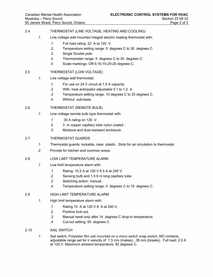
Canadian Mental Health Association ELECTRONIC CONTROL SYSTEMS FOR HVAC
Muskoka – Parry Sound Section 23 09 3360 James Street, Parry Sound, Ontario Page 2 of 3
2.4 THERMOSTAT (LINE VOLTAGE, HEATING AND COOLING)
.1 Line voltage wall mounted integral electric heating thermostat with:
.1 Full load rating: 22 A at 120 V.
.2 Temperature setting range: 5 degrees C to 30 degrees C.
.3 Single Double pole.
.4 Thermometer range: 5 degrees C to 30 degrees C.
.5 Scale markings: Off-5-10-15-20-25 degrees C.
2.5 THERMOSTAT (LOW VOLTAGE)
.1 Low voltage wall thermostat:
.1 For use on 24 V circuit at 1.5 A capacity.
.2 With heat anticipator adjustable 0.1 to 1.2 A.
.3 Temperature setting range: 10 degrees C to 25 degrees C.
.4 Without sub-base.
2.6 THERMOSTAT (REMOTE BULB)
.1 Line voltage remote bulb type thermostat with:
.1 30 A rating on 120 V.
.2 3 m copper capillary tube nylon coated .
.3 Moisture and dust-resistant enclosure .
2.7 THERMOSTAT GUARDS
.1 Thermostat guards: lockable, clear plastic . Slots for air circulation to thermostat.
.2 Provide for kitchen and common areas.
2.8 LOW LIMIT TEMPERATURE ALARM
.1 Low limit temperature alarm with:
.1 Rating: 10.2 A at 120 V 6.5 A at 240 V.
.2 Sensing bulb and 1.5 6 m long capillary tube.
.3 Switching action: manual .
.4 Temperature setting range: 0 degrees C to 15 degrees C.
2.9 HIGH LIMIT TEMPERATURE ALARM
.1 High limit temperature alarm with:
.1 Rating 10 A at 120 V 6 A at 240 V.
.2 Positive lock-out.
.3 Manual reset only after 14 degrees C drop-in temperature.
.4 Cut-out setting: 50 degrees C.
2.10 SAIL SWITCH
.1 Sail switch, Polyester film sail mounted on a micro switch snap switch, NO contacts, adjustable range set for ir velocity of 1.3 m/s (makes), .38 m/s (breaks). Full load: 2.0 A at 120 V. Maximum ambient temperature: 82 degrees C.
Canadian Mental Health Association ELECTRONIC CONTROL SYSTEMS FOR HVAC
Muskoka – Parry Sound Section 23 09 3360 James Street, Parry Sound, Ontario Page 3 of 3
2.11 FLOW SWITCH
.1 Flow switch for 60 L/s water/glycol, pipe size as indicated, CSA Enclosure , rated at 16] A at 120 V. Maximum liquid temperature: 121 degrees C. Maximum liquid gauge pressure of 1034 kPa ambient temperature range 5 degrees C to 82 degrees C.
2.12 PRESSURE SWITCH
.1 Pressure switch for water/glycol at range of 24 kPa to gauge pressure of 1034 kPa with auto reset, contacts open on rise. Maximum allowable gauge pressure of 1.2MPa. Full load 16A at 120V, ULC rated.
Part 3 EXECUTION
3.1 MANUFACTURER'S INSTRUCTIONS
.1 Compliance: comply with manufacturer's written recommendations or specifications, including product technical bulletins, handling, storage and installation instructions, and datasheet.
3.2 INSTALLATION
.1 Install control devices.
.2 On outside wall, mount thermostats on bracket or insulated pad 25 mm from exterior wall.
.3 Install remote sensing device and capillary tube in metallic conduit. Conduit enclosing capillary tube must not touch heater or heating cable.
3.3 CLEANING
.1 Upon completion and verification of performance of installation, remove surplus materials, excess materials, rubbish, tools and equipment.
END OF SECTION

Canadian Mental Health Association FACILITY NATURAL GAS PIPING
Muskoka – Parry Sound Section 23 11 2360 James Street, Parry Sound, Ontario Page 1 of 4
Part 1 GENERAL
1.1 SUMMARY
.1 Related Sections:
.1 Section 21 05 01 – Common Work Results for Mechanical.
.2 Section 23 05 01 - Installation of Pipework.
.3 Section 23 08 01 - Mechanical Performance Verification.
1.2 REFERENCES
.1 American Society of Mechanical Engineers (ASME)
.1 ASME B16.5-[03], Pipe Flanges and Flanged Fittings.
.2 American Society for Testing and Materials International (ASTM)
.1 ASTM A53/A53M-[04], Standard Specification for Pipe, Steel, Black and Hot-Dipped, Zinc Coated, Welded and Seamless.
.3 Canadian Standards Association (CSA International)
.1 CSA W47.1-[03], Certification of Companies for Fusion Welding of Steel.
.4 Canadian Standards Association (CSA)/Canadian Gas Association (CGA)
.1 CAN/CSA B149.1, Natural Gas and Propane Installation Code Handbook.
.5 Health Canada/Workplace Hazardous Materials Information System (WHMIS)
.1 Material Safety Data Sheets (MSDS).
1.3 SUBMITTALS
.1 Submittals in accordance with Section 21 05 01 – Common Work Results for Mechanical.
.2 Product Data:
.1 Submit manufacturer's printed product literature, specifications and datasheet for piping, fittings and equipment.
.2 Indicate on manufacturer’s catalogue literature following: valves.
.3 Test Reports: submit certified test reports from approved independent testing laboratories indicating compliance with specifications for specified performance characteristics and physical properties.
.4 Certificates: submit certificates signed by manufacturer certifying that materials comply with specified performance characteristics and physical properties.
.5 Instructions: submit manufacturer's installation instructions.
.6 Closeout Submittals: submit maintenance and engineering data for incorporation into manual specified in Section 21 05 01 – Common Work Results for Mechanical.
1.4 QUALITY ASSURANCE
.1 Pre-Installation Meeting:
.1 Convene pre-installation meeting one week prior to beginning work of this Section and on-site installations in accordance with Section 21 05 01 – Common Work Results for Mechanical.
.1 Verify project and pressure requirements.
.2 Review installation conditions.

Canadian Mental Health Association FACILITY NATURAL GAS PIPING
Muskoka – Parry Sound Section 23 11 2360 James Street, Parry Sound, Ontario Page 2 of 4
.3 Co-ordination with other building sub-trades.
.4 Review manufacturer's installation instructions and warranty requirements.
1.5 SCOPE OF WORK
.1 Do not interrupt natural-gas service to facilities occupied by the owner unless permitted under the following conditions and then only after arranging to provide purging and start-up of natural-gas supply.
.2 Notify Architect and Owner no fewer than one week in advance of proposed interruption of natural-gas service. Do not proceed with interruption of natural-gas service without Architect and Owner’s permission.
.3 Arrange for and provide a new gas meter to replace the existing meter of suitable increased capacity.
.4 Disconnect, cap and demolish portions of the existing gas piping for the existing building AHU equipment. Cap on the ground level at the existing meter.
.5 Provide new natural gas piping for the new RTU-1 from the existing meter and re-connect existing boiler equipment.
1.6 DELIVERY, STORAGE AND HANDLING
.1 Waste Management and Disposal:
.1 Separate waste materials for reuse and recycling
Part 2 PRODUCTS
2.1 PIPE
.1 Steel pipe: to ASTM A53/A53M, Schedule 40, seamless as follows:
.1 NPS 1/2 to 2, screwed.
.2 NPS 2 1/2 and over, plain end.
.2 Copper tube: to ASTM B837.
2.2 JOINTING MATERIAL
.1 Screwed fittings: pulverized lead paste.
.2 Welded fittings: to CSA W47.1.
.3 Flange gaskets: non-metallic flat.
2.3 FITTINGS
.1 Steel pipe fittings, screwed, flanged or welded:
.1 Malleable iron: screwed, banded, Class 150.
.2 Steel pipe flanges and flanged fittings: to ASME B16.5.
.3 Welding: butt-welding fittings.
.4 Unions: malleable iron, brass to iron, ground seat, to ASTM A47/A47M.
.5 Bolts and nuts: to ASME B18.2.1.
.6 Nipples: schedule 40, to ASTM A53/A53M.
.2 Copper pipe fittings, screwed, flanged or soldered:
.1 Cast copper fittings: to ASME B16.18.

Canadian Mental Health Association FACILITY NATURAL GAS PIPING
Muskoka – Parry Sound Section 23 11 2360 James Street, Parry Sound, Ontario Page 3 of 4
.2 Wrought copper fittings: to ASME B16.22.
2.4 VALVES: NPS 2 (DN 50) and Smaller
.1 Provincial Code approved, lubricated ball type.
.2 Comply with ASME B16.33.
.3 CWP Rating: 125 psig (862 kPa).
.4 Threaded Ends: Comply with ASME B1.20.1.
.5 Dryseal Threads on Flare Ends: Comply with ASME B1.20.3.
.6 Listing: Listed and labeled by an NRTL acceptable to authorities having jurisdiction for valves 1 inch (25 mm) and smaller.
.7 Service Mark: Valves 1-1/4 inches (32 mm) to NPS 2 (DN 50) shall have initials "WOG" permanently marked on valve body.
2.1 VALVES: NPS 2-1/2 (DN 65) and Larger
.1 Provincial Code approved, lubricated ball type.
.2 Comply with ASME B16.38.
.3 CWP Rating: 125 psig (862 kPa).
.4 Flanged Ends: Comply with ASME B16.5 for steel flanges.
.5 Service Mark: Initials "WOG" shall be permanently marked on valve body.
Part 3 EXECUTION
3.1 MANUFACTURER'S INSTRUCTIONS
.1 Compliance: comply with manufacturer's written recommendations or specifications, including product technical bulletins, handling, storage and installation instructions, and datasheet.
3.2 PIPING
.1 Install in accordance with Section 23 05 01 - Installation of Pipework, [CAN/CSA B149.1.
.2 Install drip points:
.1 At low points in piping system.
.2 At connections to equipment.
3.3 VALVES
.1 Install valves with stems upright or horizontal.
.2 Install valves at branch take-offs to isolate pieces of equipment, and as indicated.
3.4 FIELD QUALITY CONTROL
.1 Site Tests/Inspection:
.1 Test system in accordance with CAN/CSA B149.1. and requirements of authorities having jurisdiction.
.2 Performance Verification:
.1 Refer to Section 23 08 01 – Mechanical Performance Verification.

Canadian Mental Health Association FACILITY NATURAL GAS PIPING
Muskoka – Parry Sound Section 23 11 2360 James Street, Parry Sound, Ontario Page 4 of 4
3.5 ADJUSTING
.1 Purging: purge after pressure test in accordance with CAN/CSA B149.1.
.2 Pre-Start-Up Inspections:
.1 Check vents from regulators, control valves, terminate outside building in approved location, protected against blockage, damage.
.2 Check gas trains, entire installation is approved by authority having jurisdiction.
3.6 CLEANING
.1 Cleaning: in accordance with Section CAN/CSA B149.1.
.2 Upon completion and verification of performance of installation, remove surplus materials, excess materials, rubbish, tools and equipment.
END OF SECTION

Canadian Mental Health Association METAL DUCTS - LOW PRESSURE
TO 500 PA
Muskoka – Parry Sound Section 23 31 1360 James Street, Parry Sound, Ontario Page 1 of 4
Part 1 GENERAL
1.1 SUMMARY
.1 Section Includes:
.1 Materials and installation of low-pressure metallic ductwork, joints and accessories.
.2 Related Sections:
.1 Section 21 05 01 - Common Work Results for Mechanical.
.2 Section 23 05 29 - Hangers and Supports for HVAC Piping and Equipment.
.3 Section 23 05 94 - Pressure Testing of Ducted Air Systems
.4 Section 23 33 00 – Air Duct Accessories.
.3 Include cleaning of oil and grease on non-insulated or insulated duct on exterior.
.4 For exposed ductwork in finished areas, include prime painting, first coat, ready for finishing by division 09.
1.2 REFERENCES
.1 American Society of Heating, Refrigerating and Air-Conditioning Engineers, Inc. (ASHRAE).
.2 American Society for Testing and Materials International, (ASTM).
.1 ASTM A480/A480M-03c, Standard Specification for General Requirements for Flat-Rolled Stainless and Heat-Resisting Steel Plate, Sheet and Strip.
.2 ASTM A635/A635M-02, Standard Specification for Steel, Sheet and Strip, Heavy-Thickness Coils, Carbon, Hot Rolled.
.3 ASTM A653/A653M-03, Standard Specification for Steel Sheet, Zinc Coated (Galvanized) or Zinc-Iron Alloy Coated (Annealed) by the Hot-Dip Process.
.3 Health Canada/Workplace Hazardous Materials Information System (WHMIS).
.1 Material Safety Data Sheets (MSDS).
.4 National Fire Protection Association (NFPA).
.1 NFPA 90A-02, Standard for the Installation of Air-Conditioning and Ventilating Systems.
.2 NFPA 90B-02, Standard for the Installation of Warm Air Heating and Air-Conditioning Systems.
.5 Sheet Metal and Air Conditioning Contractors' National Association (SMACNA).
.1 SMACNA HVAC Duct Construction Standards - Metal and Flexible, 2nd Edition 1995 and Addendum No. 1, 1997.
.2 SMACNA HVAC Air Duct Leakage Test Manual, 1985, 1st Edition.
1.3 SUBMITTALS
.1 Submit shop drawings and product data in accordance with Submittal Procedures .
.2 Product Data: submit WHMIS MSDS - Material Safety Data Sheets for:
.1 Sealants.
.2 Tape.
.3 Proprietary Joints.

Canadian Mental Health Association METAL DUCTS - LOW PRESSURE
TO 500 PA
Muskoka – Parry Sound Section 23 31 1360 James Street, Parry Sound, Ontario Page 2 of 4
1.4 QUALITY ASSURANCE
.1 Certification of Ratings:
.1 Catalogue or published ratings shall be those obtained from tests carried out by manufacturer or independent testing agency signifying adherence to codes and standards.
1.5 DELIVERY, STORAGE AND HANDLING
.1 Protect on site stored or installed absorptive material from moisture damage.
.2 Waste Management and Disposal:
.1 Separate waste materials for reuse and recycling.
1.6 SEAL CLASSIFICATION
.1 Classification as follows:
Maximum Pressure Pa SMACNA Seal Class500 C250 C125 C125 Unsealed
.2 Seal classification:
.1 Class A: longitudinal seams, transverse joints, duct wall penetrations and connections made airtight with sealant and tape.
.2 Class B: longitudinal seams, transverse joints and connections made airtight with sealant tape or combination thereof .
.3 Class C: transverse joints and connections made air tight with sealant or combination thereof . Longitudinal seams unsealed.
1.7 SEALANT
.1 Sealant: oil resistant, water borne , polymer type flame resistant duct sealant. Temperature range of minus 30 degrees C to plus 93 degrees C.
1.8 TAPE
.1 Tape: polyvinyl treated, open weave fibreglass tape, 50 mm wide.
1.9 DUCT LEAKAGE
.1 In accordance with SMACNA HVAC Air Duct Leakage Test Manual .
1.10 FITTINGS
.1 Fabrication: to SMACNA .
.2 Radiused elbows.
.1 Rectangular: standard radius short radius with single thickness turning vanes Centreline radius: 1.5 times width of duct .
.2 Round: smooth radius five piece . Centreline radius: 1.5 times diameter.
.3 Mitred elbows, rectangular:
.1 To 400 mm: with single double thickness turning vanes.
.2 Over 400 mm: with double thickness turning vanes.
.4 Branches:

Canadian Mental Health Association METAL DUCTS - LOW PRESSURE
TO 500 PA
Muskoka – Parry Sound Section 23 31 1360 James Street, Parry Sound, Ontario Page 3 of 4
.1 Rectangular main and branch: with radius on branch 1.5 times width of duct 45 degrees entry on branch .
.2 Round main and branch: enter main duct at 45 degrees with conical connection .
.3 Provide volume control damper in branch duct near connection to main duct.
.4 Main duct branches: with splitter damper.
.5 Transitions:
.1 Diverging: 20 degrees maximum included angle.
.2 Converging: 30 degrees maximum included angle.
.6 Offsets:
.1 Full short radiused elbows as indicated .
.7 Obstruction deflectors: maintain full cross-sectional area.
.1 Maximum included angles: as for transitions .
1.11 FIRE STOPPING
.1 Provide retaining angles around duct, on both sides of fire separation penetrations.
.2 Fire stopping material and installation must not distort duct.
1.12 GALVANIZED STEEL
.1 Lock forming quality: to ASTM A653/A653M, Z90 zinc coating.
.2 Thickness, fabrication and reinforcement: to ASHRAE SMACNA .
.3 Joints: to ASHRAE SMACNA proprietary manufactured duct joint . Proprietary manufactured flanged duct joint to be considered to be a class A seal .
1.13 HANGERS AND SUPPORTS
.1 Hangers and Supports: in accordance with Section 23 05 29 - Hangers and Supports for HVAC Piping and Equipment .
.1 Strap hangers: of same material as duct but next sheet metal thickness heavier than duct .
.1 Maximum size duct supported by strap hanger: 500 .
.2 Hanger configuration: to ASHRAE and SMACNA.
.3 Hangers: black galvanized steel angle with black galvanized steel rods to ASHRAE and SMACNA following table :
Duct Size Angle Size Rod Size(mm) (mm) (mm)
up to 750 25 x 25 x 3 6751 to 1050 40 x 40 x 3 61051 to 1500 40 x 40 x 3 101501 to 2100 50 x 50 x 3 102101 to 2400 50 x 50 x 5 102401 and over 50 x 50 x 6 10
.4 Upper hanger attachments:
.1 For concrete: manufactured concrete inserts.
.2 For steel joist: manufactured joist clamp steel plate washer .
.3 For steel beams: manufactured beam clamps:

Canadian Mental Health Association METAL DUCTS - LOW PRESSURE
TO 500 PA
Muskoka – Parry Sound Section 23 31 1360 James Street, Parry Sound, Ontario Page 4 of 4
Part 2 EXECUTION
2.1 GENERAL
.1 Do work in accordance with NFPA 90A NFPA 90B ASHRAE SMACNA as indicated .
.2 Do not break continuity of insulation vapour barrier with hangers or rods.
.1 Insulate strap hangers 100 mm beyond insulated duct Ensure diffuser is fully seated .
.3 Support risers in accordance with ASHRAE SMACNA as indicated .
.4 Install breakaway joints in ductwork on sides of fire separation.
.5 Install proprietary manufactured flanged duct joints in accordance with manufacturer's instructions .
.6 Manufacture duct in lengths and diameter to accommodate installation of acoustic duct lining .
2.2 HANGERS
.1 Strap hangers: install in accordance with SMACNA .
.2 Angle hangers: complete with locking nuts and washers.
.3 Hanger spacing: in accordance with ASHRAE SMACNA as follows:
Duct Size Spacing(mm) (mm)
to 1500 30001501 and over 2500
2.3 SEALING AND TAPING
.1 Apply sealant to outside of joint to manufacturer's recommendations.
.2 Bed tape in sealant and recoat with minimum of one coat of sealant to manufacturers recommendations.
2.4 LEAKAGE TESTS
.1 Refer to Section 23 05 94 - Pressure Testing of Ducted Air Systems .
.2 In accordance with SMACNA HVAC Duct Leakage Test Manual .
.3 Do leakage tests in sections.
.4 Make trial leakage tests as instructed to demonstrate workmanship.
.5 Do not install additional ductwork until trial test has been passed.
.6 Test section minimum of 30 m long with not less than three branch takeoffs and two 90 degrees elbows.
.7 Complete test before performance insulation or concealment Work.
END OF SECTION

Canadian Mental Health Association AIR DUCT ACCESSORIES
Muskoka – Parry Sound Section 23 33 0060 James Street, Parry Sound, Ontario
Page 1 of 5
Part 1 GENERAL
1.1 SUMMARY
.1 Section Includes:
.1 Materials and installation for duct accessories including flexible connections, access doors, vanes, filters and collars.
.2 Section 21 05 00 – Common Work Results for Mechanical.
.3 Section 23 09 00 –Controls for HVAC Systems.
1.2 REFERENCES
.1 Sheet Metal and Air Conditioning Contractors' National Association (SMACNA).
.1 SMACNA - HVAC Duct Construction Standards - Metal and Flexible, 95.
1.3 SUBMITTALS
.1 Submittals in accordance with Section 21 05 00 – Common Work Results for Mechanical.
.2 Product Data:
.1 Submit manufacturer's printed product literature, specifications and data sheet. Indicate the following:
.1 Flexible connections.
.2 Duct access doors.
.3 Turning vanes.
.4 Instrument test ports.
.5 Filters and filter housings
.2 Certification of ratings: catalogue or published ratings to be those obtained from tests carried out by manufacturer or independent testing agency signifying adherence to codes and standards.
.3 Certificates: submit certificates signed by manufacturer certifying that materials comply with specified performance characteristics and physical properties.
.4 Instructions: submit manufacturer's installation instructions.
.5 Manufacturer's Field Reports: manufacturer's field reports specified.
.6 Closeout submittals: submit maintenance and engineering data for incorporation into manual specified in Section 21 05 00 – Common Work Results for Mechanical.
1.4 DELIVERY, STORAGE AND HANDLING
.1 Waste Management and Disposal:
.1 Separate waste materials for reuse and recycling.
1.5 SCOPE OF WORK
.1 Provides duct accessories for BAS and control of airside equipment included but not limited to flexible connections, duct access doors, turning vanes, instrument test ports, balancing dampers, splitters.
.2 Provide access doors for heating coils at each side of the coil.
.3 Provide silencers for the fourth floor mechanical room branch supply and return ducts to the fourth floor and main supply and return ducts to the third and lower floors.

Canadian Mental Health Association AIR DUCT ACCESSORIES
Muskoka – Parry Sound Section 23 33 0060 James Street, Parry Sound, Ontario
Page 2 of 5
Part 2 PRODUCTS
2.1 GENERAL
.1 Manufacture in accordance with SMACNA - HVAC Duct Construction Standards.
2.2 FLEXIBLE CONNECTIONS
.1 Frame: galvanized sheet metal frame mm thick with fabric clenched by means of double locked seams.
.2 Material:
.1 Fire resistant, self-extinguishing, neoprene coated glass fabric, temperature rated at minus 40 degrees C to plus 90 degrees C, density of 1.3 kg/m2.
2.3 ACCESS DOORS IN DUCTS
.1 Non-Insulated Ducts: sandwich construction of same material as duct, one sheet metal thickness heavier, minimum 0.6 mm thick complete with sheet metal angle frame.
.2 Insulated Ducts: sandwich construction of same material as duct, one sheet metal thickness heavier, minimum 0.6 mm thick complete with sheet metal angle frame and 25 mm thick rigid glass fibre insulation.
.3 Welded kitchen exhaust duct in accordance with NFPA 96. Ductmate F2 Grease Duct Sandwich Access Door with ceramic fibre gasket, for use with Duct Wrap System.
.4 Hardware:
.1 Up to 300 x 300 mm: two sash locks complete with safety chain .
.2 301 to 450 mm: four sash locks complete with safety chain .
.3 451 to 1000 mm: piano hinge and minimum two sash locks.
.4 Doors over 1000 mm: piano hinge and two handles operable from both sides.
.5 Hold open devices.
.6 300 x 300 mm glass viewing panels .
2.4 ACCESS DOORS IN EQUIPMENT
.1 Insulated walls: sandwich construction of same material as equipment, one sheet metal thickness heavier, minimum 1.6 mm thick complete with metal angle frame and 25 mm thick foam board, foil faced or neoprene insulation.
.2 Gaskets: neoprene .
.3 Hardware:
.1 451 to 1000 mm: piano hinge and minimum two sash locks.
.2 Doors over 1000 mm: piano hinge and two handles operable from both sides.
.3 Hold open devices.
.4 300 x 300 mm glass viewing panels .
2.5 TURNING VANES
.1 Factory or shop fabricated single thickness without trailing edge , to recommendations of SMACNA and as indicated.
2.6 SPIN-IN COLLARS
.1 Conical galvanized sheet metal spin-in collars with lockable butterfly damper.
.2 Sheet metal thickness to co-responding round duct standards.

Canadian Mental Health Association AIR DUCT ACCESSORIES
Muskoka – Parry Sound Section 23 33 0060 James Street, Parry Sound, Ontario
Page 3 of 5
2.7 DUCT FILTER AND FILTER HOUSING
.1 Filters:
.1 Basis-of-Design Product: Camfil’s AP-Thirteen, high efficiency, high capacity, pleated panel filter, MERV 13 when evaluated per ASHRAE Standard 52.2.
.1 4” (100mm) nominal depth filter.
.2 Filter shall have 11 pleats per linear foot.
.3 Filter sizes and airflows shall be:
.1 AC-1: One and a half 24x24x4 (600mmx600mmx100mm) filter, 3000cfm (1415L/s).
.2 AC-2a: One 20x20x4 (500mmx500mmx100mm) filter 1200cfm (565L/s).
.3 AC-4a&ac-4b: One 20x20x4 (500mmx500mmx100mm) filter 1600cfm (755L/s).
.2 Filter Housing:
.1 Basis-of-Design Product: Camfil’s GlidePack MultiTrack 13, short depth multi-stage air filter housing with adaptable tracks.
.2 Filter housing shall be multi-stage air filter housing consisting of 16-gauge galvanized steel enclosure, multi-filter adaptable extruded aluminum filter mounting track, dual-access doors, three static pressure taps, door and filter gaskets and seals. In-line housing depth shall not exceed 13” (325mm).
.3 Sizes shall be:
.1 AC-1: 24”Hx36”Wx4”D (600mmHx900mmWx100mmD)
.2 AC-2a: 24”Hx24”Wx4”D (600mmHx600mmWx100mmD)
.3 AC-4a and AC-4b: 24”Hx24”Wx4”D (600mmHx600mmWx100mmD)
.4 Housing construction shall be:
.1 Housing shall be constructed of 16-gauge galvanized steel (stainless steel or aluminum*) with standing flanges to facilitate attachment to other HVAC system components. Corner posts of Z-channel construction shall ensure housing stability and rigidity. The housing shall be weatherproof and suitable for rooftop/outdoor installation without modification.
.2 The housing shall incorporate the capability of multiple stages of filtration without modification to the housing. A filter track, of extruded aluminum construction shall be an integral component of housing construction. The track shall be designed to accommodate three 2” filters, or one 2” filter and one 4” filter.
.3 Dual access swing-open doors shall include high-memory sponge neoprene gasket to facilitate a door-to-filter seal against all individual stages of filtration. Each door shall be equipped with adjustable and replaceable positive sealing UV-resistant star-style knobs and replaceable door hinges.
.4 The housing shall include two pneumatic fittings to allow the installation of static pressure gauge(s) to evaluate pressure drop across the prefilter, the secondary filter, the final filter, or any combination of the installed filters.
.5 Housing performance shall be as follows:
.1 Leakage at rated airflow, upstream to downstream of filter and slide mechanism shall not exceed 1% at 3.0” w.g. Leakage into or out of the housing shall be less than 1% at 3.0” w.g.
.2 Accuracy of pneumatic pressure fittings, when used to evaluate a single-stage, or multiple filter stages, shall be accurate within ± 3% at 0.6” w.g.

Canadian Mental Health Association AIR DUCT ACCESSORIES
Muskoka – Parry Sound Section 23 33 0060 James Street, Parry Sound, Ontario
Page 4 of 5
.3 Housing integrity to listed performance values shall be available on
.4 request from the housing manufacturer.
.5 Manufacturer shall provide evidence of facility certification to ISO 9001:2008.
Part 3 EXECUTION
3.1 MANUFACTURER'S INSTRUCTIONS
.1 Compliance: comply with manufacturer's written recommendations or specifications, including product technical bulletins, handling, storage and installation instructions, and data sheet.
3.2 INSTALLATION
.1 Flexible Connections:
.1 Install in following locations:
.1 Inlets and outlets to supply air units and fans.
.2 Inlets and outlets of exhaust and return air fans.
.3 As indicated.
.2 Length of connection: 100 mm.
.3 Minimum distance between metal parts when system in operation: 75 mm.
.4 Install in accordance with recommendations of SMACNA.
.5 When fan is running:
.1 Ducting on sides of flexible connection to be in alignment.
.2 Ensure slack material in flexible connection.
.2 Access Doors and Viewing Panels:
.1 Size:
.1 600 x 600 mm for person size entry.
.2 300 x 300 mm or as allowed by duct dimension for servicing entry.
.3 200 x 200 mm for viewing.
.2 Locations:
.1 Fire and smoke dampers.
.2 Kitchen exhaust duct at each change of direction.
.3 Hydronic heating coils.
.4 Control dampers.
.5 Devices requiring maintenance.
.6 Required by code.
.7 Central AHU hydronic heating coil.
.8 Elsewhere as indicated.
.3 Turning vanes:
.1 Install in accordance with recommendations of SMACNA and as indicated.
.4 Filter racks:
.1 Install in accordance with Manufacturers written instructions
.2 Observe all directional arrows.

Canadian Mental Health Association AIR DUCT ACCESSORIES
Muskoka – Parry Sound Section 23 33 0060 James Street, Parry Sound, Ontario
Page 5 of 5
3.3 FIELD QUALITY CONTROL
.1 Manufacturer's Field Services:
.1 Manufacturer's Field Services: provide manufacturer's field services consisting of product use recommendations and periodic site visits for inspection of product installation in accordance with manufacturer's instructions.
3.4 CLEANING
.1 Perform cleaning operations in accordance with manufacturer's recommendations.
.2 Upon completion and verification of performance of installation, remove surplus materials, excess materials, rubbish, tools and equipment.
END OF SECTION

Canadian Mental Health Association BALANCING DAMPERS
Muskoka – Parry Sound Section 23 33 1460 James Street, Parry Sound, Ontario Page 1 of 2
PART 1 GENERAL
1.1 SUMMARY
.1 Section Includes:
.1 Balancing dampers for mechanical forced air ventilation and air conditioning systems.
.2 Sustainable requirements for construction and verification.
.2 Related Sections:
.1 23 31 13 Metal Ducts - Low Pressure to 500 Pa.
1.2 REFERENCES
.1 Sheet Metal and Air Conditioning National Association (SMACNA)
.1 SMACNA HVAC Duct Construction Standards, Metal and Flexible-2006.
1.3 SUBMITTALS
.1 Product Data:
.1 Submit manufacturer's printed product literature, specifications and datasheet. Include product characteristics, performance criteria, and limitations.
1.4 DELIVERY, STORAGE, AND HANDLING
.1 Waste Management and Disposal:
.1 Construction/Demolition Waste Management and Disposal: separate waste materials for re-use and recycling.
PART 2 PRODUCTS
2.1 GENERAL
.1 Manufacture to SMACNA standards.
2.2 SPLITTER DAMPERS
.1 Fabricate from same material as duct but one sheet metal thickness heavier, with appropriate stiffening.
.2 Single thickness construction.
.3 Control rod with locking device and position indicator.
.4 Rod configuration to prevent end from entering duct.
.5 Pivot: piano hinge.
.6 Folded leading edge.
2.3 SINGLE BLADE DAMPERS
.1 Fabricate from same material as duct, but one sheet metal thickness heavier. V-groove stiffened.
.2 Size and configuration to recommendations of SMACNA. ,
.3 Locking quadrant with shaft extension to accommodate insulation thickness .
.4 Inside and outside nylon end bearings.

Canadian Mental Health Association BALANCING DAMPERS
Muskoka – Parry Sound Section 23 33 1460 James Street, Parry Sound, Ontario Page 2 of 2
.5 Channel frame of same material as adjacent duct, complete with angle stop.
PART 3 EXECUTION
3.1 MANUFACTURER'S INSTRUCTIONS
.1 Compliance: comply with manufacturer's written recommendations or specifications, including product technical bulletins, handling, storage and installation instructions, and datasheet.
3.2 INSTALLATION
.1 Install where required for best practices.
.2 Install in accordance with recommendations of SMACNA and in accordance with manufacturer's instructions.
.3 Locate balancing dampers in each branch duct, for supply, return and exhaust systems.
.4 Run-outs to registers and diffusers: install single blade damper located as close as possible to main ducts.
.5 Operators in ceiling space shall be in plain site and accessible.
.6 Dampers: vibration free.
.7 Ensure damper operators are observable and accessible.
.8 Corrections and adjustments conducted by the air balancing contractor.
3.3 CLEANING
.1 Upon completion and verification of performance of installation, remove surplus materials, excess materials, rubbish, tools and equipment.
END OF SECTION

Canadian Mental Health Association DAMPERS OPERATING
Muskoka – Parry Sound Section 23 33 1560 James Street, Parry Sound, Ontario Page 1 of 2
Part 1 GENERAL
1.1 SUMMARY
.1 Section Includes:
.1 Operating dampers for mechanical forced air ventilation and air conditioning systems.
.2 Related Sections:
.1 23 09 33 Electronic Control Systems for HVAC
1.2 REFERENCES
.1 American Society for Testing and Materials International (ASTM)
.1 ASTM A653/A653M-[04a], Standard Specification for Steel Sheet, Zinc-Coated (Galvanized) or Zinc-Iron Alloy-Coated (Galvannealed) by Hot-Dip Process.
1.3 SUBMITTALS
.1 Product Data:
.1 Submit manufacturer's printed product literature, specifications and datasheet in accordance with Section01 33 00 - Submittal Procedures. Include product characteristics, performance criteria, and limitations.
.2 Indicate the following:
.1 Performance data.
.2 Damper roughing in dimensions,
.3 Operator characteristics,
.4 Mounting arrangement.
.2 Closeout Submittals
.1 Provide maintenance data for incorporation into manual specified in Section 01 78 00 - Closeout Submittals.
1.4 DELIVERY, STORAGE, AND HANDLING
.1 Packing, shipping, handling and unloading:
.1 Deliver, store and handle materials in accordance with manufacturer's written instructions.
.2 Waste Management and Disposal:
.1 Separate waste materials for reuse or recycling.
Part 2 PRODUCTS
2.1 MULTI-LEAF DAMPERS
.1 Opposed or parallel blade type as indicated.
.2 Extruded aluminum, interlocking blades, complete with extruded vinyl seals, spring stainless steel side seals, extruded aluminum frame.
.3 Pressure fit self-lubricated bronze bearings.

Canadian Mental Health Association DAMPERS OPERATING
Muskoka – Parry Sound Section 23 33 1560 James Street, Parry Sound, Ontario Page 2 of 2
.4 Linkage: plated steel tie rods, brass pivots and plated steel brackets, complete with plated steel control rod.
.5 Operator: Belimo NFB 24 series, 24 V, Spring Return.
.6 Performance:
.1 Leakage: in closed position less than 2% of rated air flow at 250 Pa differential across damper.
.2 Pressure drop: at full open position less than 64 Pa differential across damper at 1510 l/s.
.7 Insulated aluminum dampers:
.1 Frames: insulated with extruded polystyrene foam with RSI 0.88.
.2 Blades: constructed from aluminum extrusions with internal hollows insulated with polyurethane or polystyrene foam, RSI 0.88.
2.2 BACK DRAFT DAMPERS
.1 Automatic gravity operated, multi leaf, aluminum construction with nylon bearings, as indicated.
Part 3 EXECUTION
3.1 MANUFACTURER'S INSTRUCTIONS
.1 Compliance: comply with manufacturer's written recommendations or specifications, including product technical bulletins, handling, storage and installation instructions, and datasheet.
3.2 INSTALLATION
.1 Install where indicated.
.2 Install in accordance with recommendations of SMACNA and manufacturer's instructions.
.3 Seal multiple damper modules with silicon sealant.
.4 Ensure dampers are observable and accessible.
3.3 CLEANING
.1 Upon completion and verification of performance of installation, remove surplus materials, excess materials, rubbish, tools and equipment.
END OF SECTION

Canadian Mental Health Association FIRE DAMPERS
Muskoka – Parry Sound Section 23 33 1660 James Street, Parry Sound, Ontario Page 1 of 3
PART 1 GENERAL
1.1 SUMMARY
.1 Section Includes:
.1 Fire dampers.
.2 Related Sections:
.1 23 31 13 Metal Ducts – Low Pressure to 500 Pa.
1.2 REFERENCES
.1 American National Standards Institute/National Fire Protection Association (ANSI/NFPA).
.1 ANSI/NFPA 90A-2012, Standard for the Installation of Air Conditioning and Ventilating Systems.
.2 Underwriters Laboratories of Canada (ULC)
.1 CAN4-S112-M1990, Fire Test of Fire Damper Assemblies.
.2 CAN4-S112.2-M84, Standard Method of Fire Test of Ceiling Firestop Flap Assemblies.
.3 ULC-S505-2004, Fusible Links for Fire Protection Service.
1.3 SUBMITTALS
.1 Product Data:
.1 Submit manufacturer's printed product literature, specifications and datasheet in accordance with Section 21 05 01 - Common Work Results for Mechanical. Include product characteristics, performance criteria, and limitations.
.2 Indicate the following:
.1 Fire dampers.
.2 Fire stop flaps.
.3 Fusible links.
.4 Design details of break-away joints.
.3 Certificates: submit certificates signed by manufacturer certifying that materials comply with specified performance characteristics and physical properties.
.4 Instructions: submit manufacturer's installation instructions.
.2 Closeout Submittals:
.1 Provide maintenance data for incorporation into manual specified in Section 21 05 01 - Common Work Results for Mechanical.
1.4 QUALITY ASSURANCE
.1 Certificates:
.1 Catalogue or published ratings those obtained from tests carried out by manufacturer or those ordered by manufacturer from independent testing agency signifying adherence to codes and standards.
1.5 MAINTENANCE
.1 Extra Materials:
.1 Provide maintenance materials in accordance with Section 21 05 01 Common Work Results for Mechanical.

Canadian Mental Health Association FIRE DAMPERS
Muskoka – Parry Sound Section 23 33 1660 James Street, Parry Sound, Ontario Page 2 of 3
.2 Provide following:
.1 6 fusible links of each type.
1.6 DELIVERY, STORAGE, AND HANDLING
.1 Packing, shipping, handling and unloading:
.1 Deliver, store and handle materials in accordance with manufacturer's written instructions.
.2 Waste Management and Disposal:
.1 Construction/Demolition Waste Management and Disposal: separate waste materials for reuse and recycling.
PART 2 PRODUCTS
2.1 FIRE DAMPERS
.1 Fire dampers: arrangement Type A or B or C, listed and bear label of ULC/UL , meet requirements of provincial fire authority and ANSI/NFPA 90A authorities having jurisdiction. Fire damper assemblies fire tested in accordance with CAN4-S112.
.2 Mild steel, factory fabricated for fire rating requirement to maintain integrity of fire wall and/or fire separation.
.1 Fire dampers: rated to match the partition rating in accordance with the OBC, unless otherwise indicated.
.2 Fire dampers: automatic operating type and have dynamic rating suitable for maximum air velocity and pressure differential that it will be subjected.
.3 Top hinged: offset single damper , round or square; multi-blade hinged or interlocking type; roll door type; guillotine type; sized to maintain full duct cross section.
.4 Fusible link actuated, weighted to close and lock in closed position when released or having negative-spring-closing operator for multi-leaf type or roll door type in horizontal position with vertical air flow.
.5 40 x 40 x 3 mm retaining angle iron frame, on full perimeter of fire damper, on both sides of fire separation being pierced.
.6 Equip fire dampers with steel sleeve or frame installed disruption ductwork or impair damper operation.
.7 Equip sleeves or frames with perimeter mounting angles attached on both sides of wall or floor opening. Construct ductwork in fire-rated floor-ceiling or roof-ceiling assembly systems with air ducts that pierce ceiling to conform with ULC.
.8 Design and construct dampers to not reduce duct or air transfer opening cross-sectional area.
.9 Dampers shall be installed so that the centerline of the damper depth or thickness is located in the centerline of the wall, partition of floor slab depth or thickness.
.10 Unless otherwise indicated, the installation details given in SMACNA Install Fire Damp HVAC and in manufacturer's instructions for fire dampers shall be followed.

Canadian Mental Health Association FIRE DAMPERS
Muskoka – Parry Sound Section 23 33 1660 James Street, Parry Sound, Ontario Page 3 of 3
PART 3 EXECUTION
3.1 MANUFACTURER'S INSTRUCTIONS
.1 Compliance: comply with manufacturer's written recommendations or specifications, including product technical bulletins, handling, storage and installation instructions, and datasheet.
3.2 INSTALLATION
.1 Install in accordance with ANSI/NFPA 90A and in accordance with conditions of ULC listing.
.2 Maintain integrity of fire separation.
.3 After completion and prior to concealment obtain approvals of complete installation from authority having jurisdiction.
.4 Install access door adjacent to each damper. See Section 23 33 00 - Duct Accessories .
.5 Co-ordinate with installer of fire-stopping.
.6 Ensure access doors/panels, fusible links, damper operators are easily observed and accessible.
.7 Install break-away joints of approved design on each side of fire separation.
3.3 CLEANING
.1 Upon completion and verification of performance of installation, remove surplus materials, excess materials, rubbish, tools and equipment.
END OF SECTION

Canadian Mental Health Association FLEXIBLE DUCTS
Muskoka – Parry Sound Section 23 33 4660 James Street, Parry Sound, Ontario Page 1 of 2
Part 1 GENERAL
1.1 SUMMARY
.1 Section Includes:
.1 Materials and installation of flexible ductwork, joints and accessories.
.2 Related Sections:
.1 Section 21 05 01 Common Work Results for Mechanical.
.2 Section 23 31 13 Metal Ducts
.3 Section 23 73 10 Built Up Air Handling Units
1.2 REFERENCES
.1 American Society of Heating, Refrigerating and Air-Conditioning Engineers, Inc. (ASHRAE).
.2 National Fire Protection Association (NFPA).
.1 NFPA 90A-15, Standard for the Installation of Air-Conditioning and Ventilating Systems.
.2 NFPA 90B-012, Standard for Installation of Warm Air Heating and Air-Conditioning Systems.
.3 Sheet Metal and Air-Conditioning Contractors' National Association (SMACNA).
.1 SMACNA HVAC Duct Construction Standards - Metal and Flexible, 2005
.2 SMACNA IAQ Guideline for Occupied Buildings under Construction, 2nd Edition 2007.
.4 Underwriters' Laboratories Inc. (UL).
.1 UL 181-13, Standard for Factory-Made Air Ducts and Air Connectors.
.5 Underwriters' Laboratories of Canada (ULC).
.1 CAN/ULC-S110-2013, Standard Method of Tests for Air Ducts.
1.3 SUBMITTALS
.1 Make submittals in accordance with Section 21 05 01 Common Work Results for Mechanical..
.2 Product Data: submit the following:
.1 Thermal properties.
.2 Friction loss.
.3 Acoustical loss.
.4 Leakage.
.5 Fire rating.
.3 Samples: submit samples with product data of different types of flexible duct being used in accordance with Section 01 33 00 - Submittal Procedures.
1.4 QUALITY ASSURANCE
.1 Certification of Ratings:
.1 Catalogue or published ratings to be those obtained from tests carried out by manufacturer or independent testing agency signifying adherence to codes and standards.

Canadian Mental Health Association FLEXIBLE DUCTS
Muskoka – Parry Sound Section 23 33 4660 James Street, Parry Sound, Ontario Page 2 of 2
1.5 DELIVERY, STORAGE AND HANDLING
.1 Protect on site stored or installed absorptive material from moisture damage.
.2 Waste Management and Disposal:
.1 Separate waste materials for reuse and recycling.
Part 2 PRODUCTS
2.1 GENERAL
.1 Flexmaster or approved equal.
.2 Factory fabricated to UL 181-13, tested to Can ULC S110.
.3 Pressure drop coefficients listed below are based on relative sheet metal duct pressure drop coefficient of 1.00.
.4 Flame spread rating not to exceed 25. Smoke developed rating not to exceed 50.
2.2 METALLIC - UNINSULATED
.1 Flexmaster T/L or approved equal.
.2 Type 1 : spiral wound flexible aluminum, as indicated.
.3 Performance:
.1 Factory tested to 2.5kPa without leakage.
.2 Maximum relative pressure drop coefficient: 2.0 Pa/m .
2.3 NON-METALLIC - UNINSULATED
.1 Flexmaster or approved equal.
.2 Type 3 : non-collapsible, coated aluminum foil mylar type, mechanically bonded to, and helically supported by, external steel wire, as indicated.
.3 Performance:
.1 Factory tested to 2.5kPa without leakage.
.2 Maximum relative pressure drop coefficient: 2.0 Pa/m .
2.4 METALLIC - INSULATED
.1 Flexmaster T/L-M or approved equal.
.2 R8 Factory insulation sleeve.
.3 Type 1 : spiral wound flexible aluminum, as indicated.
.4 Performance:
.1 Factory tested to 2.5kPa without leakage.
.2 Maximum relative pressure drop coefficient: 2.0 Pa/m .
Part 3 EXECUTION
3.1 DUCT INSTALLATION
.1 Install in accordance with: CAN/ULC-S110, UL-181, NFPA 90A NFPA 90B SMACNA .
END OF SECTION

Canadian Mental Health Association DUCT LINERS
Muskoka – Parry Sound Section 23 33 5360 James Street, Parry Sound, Ontario Page 1 of 3
PART 1 GENERAL
1.1 SECTION INCLUDES
.1 Materials and installation for acoustic duct lining.
1.2 RELATED SECTIONS
.1 Section 21 05 01 – Common Work Results for Mechanical.
.2 Section 23 31 13 Metal Ducts – Low Pressure to 500 Pa.
1.3 REFERENCES
.1 American Society for Testing and Materials International, (ASTM).
.1 ASTM C423-02a, Standard Test Method for Sound Absorption and Sound Absorption Coefficients by the Reverberation Room Method.
.2 ASTM C916-85(2001)e1, Standard Specification for Adhesives for Duct Thermal Insulation.
.3 ASTM C1071-00, Standard specification for Fibrous Glass Duct Lining Insulation (Thermal and Sound Absorbing Material).
.4 ASTM C1338-00, Standard Test Method for Determining Fungi Resistance of Insulation Materials and Facings.
.5 ASTM G21-96(2002), Standard Practice for Determining Resistance of Synthetic Polymeric Materials to Fungi.
.2 National Fire Protection Association (NFPA).
.1 NFPA 90A, Standard for the Installation of Air Conditioning and Ventilating Systems.
.2 NFPA 90B, Standard for the Installation of Warm Air Heating and Air Conditioning Systems.
.3 North American Insulation Manufacturers Association (NAIMA).
.1 NAIMA AH116-5th Edition, Fibrous Glass Duct Construction Standards.
.4 Sheet Metal and Air Conditioning Contractor's National Association (SMACNA).
.1 SMACNA, HVAC Duct Construction Standards, Metal and Flexible-2005.
.2 SMACNA IAQ Guideline for Occupied Buildings 2007.
.5 Underwriter's Laboratories of Canada (ULC).
.1 CAN/ULC-S102-03-EN, Methods of Test for Surface Burning Characteristics of Building Materials and Assemblies.
1.4 SUBMITTALS
.1 Submit product data in accordance with Section 21 05 01 – Common Work Results for Mechanical.
1.5 DELIVERY, STORAGE AND HANDLING
.1 Protect on site stored or install absorptive material for protection from moisture damage.
1.6 SCOPE OF WORK
.1 Provide up to 3m metres of duct lining for each return duct at floors one through three.
1.7 WASTE MANAGEMENT AND DISPOSAL
.1 Separate waste materials for reuse and recycling.

Canadian Mental Health Association DUCT LINERS
Muskoka – Parry Sound Section 23 33 5360 James Street, Parry Sound, Ontario Page 2 of 3
PART 2 PRODUCTS
2.1 DUCT LINER
.1 General:
.1 Mineral Fibre duct liner: air surface coated mat facing .
.2 Flame spread rating shall not exceed 25. Smoke development rating shall not exceed 50 when tested in accordance with CAN/ULC-S102 and NFPA 90A NFPA 90B.
.3 Recycled Content: EcoLogo certified with minimum 35 % by weight recycled content .
.4 Fungi resistance: to ASTM C1338 ASTM G21.
.2 Rigid:
.1 Use on flat surfaces where indicated .
.2 25 mm thick, to ASTM C1071 , Type 2 , fibrous glass rigid board duct liner.
.3 Density: 48 kg/m3 minimum.
.4 Thermal resistance to be minimum 0.76 (m2. degrees C)/W for 25 mm thickness 1.15 (m2.degrees C)/W for 38 mm thickness 1.53 (m2.degrees C)/W for 50 mm thickness when tested in accordance with ASTM C177, at 24 degrees C mean temperature.
.5 Maximum velocity on faced air side: 20.3 m/sec .
.6 Minimum NRC of 0.70 at 25 mm thickness based on Type A mounting to ASTM C423.
.7 Recycled Content: EcoLogo certified containing minimum 45 % by weight recycled content .
2.2 ADHESIVE
.1 Adhesive: to NFPA 90A and NFPA 90B ASTM C916.
.2 Flame spread rating shall not exceed 25. Smoke development rating shall not exceed 50. Temperature range minus 29 degrees C to plus 93 degrees C.
.3 Water-based fire retardant type.
2.3 FASTENERS
.1 Weld pins 2.0 mm diameter, length to suit thickness of insulation. Polymer Nylon Metal retaining clips, 32 mm square.
2.4 JOINT TAPE
.1 Poly-Vinyl treated open weave fiberglass membrane 50 mm wide.
2.5 SEALER
.1 Meet requirements of NFPA 90A and NFPA 90B.
.2 Flame spread rating shall not exceed 25. Smoke development rating shall not exceed 50. Temperature range minus 68 degrees C to plus 93 degrees C.
PART 3 EXECUTION
3.1 GENERAL
.1 Do work in accordance with SMACNA HVAC Duct Construction Standards - Metal and Flexible. .
.2 Line inside of ducts where indicated and as noted in the scope of work.

Canadian Mental Health Association DUCT LINERS
Muskoka – Parry Sound Section 23 33 5360 James Street, Parry Sound, Ontario Page 3 of 3
.3 Duct dimensions, as indicated, are clear inside of duct lining.
3.2 DUCT LINER
.1 Install in accordance with manufacturer's recommendations, and as follows:
.1 Fasten to interior sheet metal surface with 90 100 % coverage of adhesive to ASTM C916
.1 Exposed leading edges and transverse joints to be factory coated or coated with adhesive during fabrication.
.2 In addition to adhesive, install weld pins not less than 2 rows per surface and not more than 425 mm on centres impact driven mechanical fasteners to compress duct liner sufficiently to hold it firmly in place.
.1 Spacing of mechanical fasteners in accordance with SMACNA.
.2 In systems, where air velocities exceeds 20.3 m/sec, install galvanized sheet metal noising to leading edges of duct liner.
3.3 JOINTS
.1 Seal butt joints, exposed edges, weld pin and clip penetrations and damaged areas of liner with joint tape and sealer. Install joint tape in accordance with manufacturer's written recommendations, and as follows:
.1 Bed tape in sealer.
.2 Apply two coats of sealer over tape.
.2 Replace damaged areas of liner at discretion of the Consultant .
.3 Protect leading and trailing edges of duct sections with sheet metal nosing having 15 mm overlap and fastened to duct.
END OF SECTION

Canadian Mental Health Association HVAC FANS
Muskoka – Parry Sound Section 23 34 0060 James Street, Parry Sound, Ontario Page 1 of 5
Part 1 GENERAL
1.1 SUMMARY
.1 Section Includes:
.1 Fans, motors, accessories and hardware for commercial use.
.2 Sustainable requirements for construction and verification.
.2 Related Sections:
.1 Section 21 05 01 – Common Work Results for Mechanical.
1.2 REFERENCES
.1 Air Conditioning and Mechanical Contractors (AMCA)
.1 AMCA Publication 99-16, Standards Handbook.
.2 AMCA 300-08, Reverberant Room Method for Sound Testing of Fans.
.3 AMCA 301-14, Methods for Calculating Fan Sound Ratings from Laboratory Test Data.
.2 American National Standards Institute (ANSI)/American Society of Mechanical Engineers (ASME)
.1 ANSI/AMCA 210-2016, Laboratory Methods of Testing Fans for Aerodynamic Performance Rating.
.3 Health Canada/Workplace Hazardous Materials Information System (WHMIS)
.1 Material Safety Data Sheets (MSDS).
1.3 SYSTEM DESCRIPTION
.1 Performance Requirements:
.1 Catalogued or published ratings for manufactured items: obtained from tests carried out by manufacturer or those ordered by manufacturer from independent testing agency signifying adherence to codes and standards in force.
.2 Capacity: flow rate, static pressure, W, efficiency, revolutions per minute, power, model, size, sound power data and as indicated on schedule.
.3 Fans: statically and dynamically balanced, constructed in conformity with AMCA 99.
.4 Sound ratings: comply with AMCA 301, tested to AMCA 300. Supply unit with AMCA certified sound rating seal.
.5 Performance ratings: based on tests performed in accordance with ANSI/AMCA 210. Supply unit with AMCA certified rating seal, except for propeller fans smaller than 300 mm diameter.
1.4 SUBMITTALS
.1 Product Data:
.1 Submit manufacturer's printed product literature, specifications and datasheet in accordance with Section 01 33 00 - Submittal Procedures. Include product characteristics, performance criteria, and limitations.

Canadian Mental Health Association HVAC FANS
Muskoka – Parry Sound Section 23 34 0060 James Street, Parry Sound, Ontario Page 2 of 5
.1 Submit copies of Workplace Hazardous Materials Information System (WHMIS) Material Safety Data Sheets (MSDS) in accordance with Section 01 33 00 - Submittal Procedures.
.2 Shop Drawings:
.1 Submit shop drawings and product data in accordance with Section 01 33 00 - Submittal Procedures.
.1 Shop Drawings: submit drawings stamped and signed by professional engineer registered or licensed in the Province of Ontario, Canada.
.3 Provide :
.1 Fan performance curves showing point of operation, [BHP] [kW] and efficiency.
.2 Sound rating data at point of operation.
.4 Indicate:
.1 Motors, sheaves, bearings, shaft details.
.2 Minimum performance achievable with variable speed controllers and variable inlet vanes as appropriate.
.5 Quality assurance submittals: submit following in accordance with Section 01 33 00 - Submittal Procedures.
.1 Certificates: submit certificates signed by manufacturer certifying that materials comply with specified performance characteristics and physical properties.
.2 Instructions: submit manufacturer's installation instructions.
.6 Closeout Submittals:
.1 Provide operation and maintenance data for incorporation into manual specified in Section 01 78 00 - Closeout Submittals.
1.5 QUALITY ASSURANCE
.1 Health and Safety Requirements: do construction occupational health and safety in accordance with Section 01 35 29.06 - Health and Safety Requirements.
1.6 MAINTENANCE
.1 Extra Materials:
.1 Provide maintenance materials in accordance with Section 01 78 00 - Closeout Submittals.
.1 Spare parts to include:
.1 Matched sets of belts.
.2 Furnish list of individual manufacturer's recommended spare parts for equipment, include:
.1 Bearings and seals.
.2 Addresses of suppliers.
.3 List of specialized tools necessary for adjusting, repairing or replacing.
1.7 DELIVERY, STORAGE, AND HANDLING
.1 Packing, shipping, handling and unloading:
.1 Deliver, store and handle in accordance with Section 01 61 00 - Common Product Requirements.

Canadian Mental Health Association HVAC FANS
Muskoka – Parry Sound Section 23 34 0060 James Street, Parry Sound, Ontario Page 3 of 5
.2 Deliver, store and handle materials in accordance with manufacturer's written instructions.
.2 Waste Management and Disposal:
.1 Construction/Demolition Waste Management and Disposal: separate waste materials for reuse and recycling in accordance with Section 01 74 21 - Construction/Demolition Waste Management and Disposal.
Part 2 Products
2.1 SUSTAINABLE REQUIREMENTS
.1 Materials and products in accordance with Section 01 47 15 - Sustainable Requirements: Construction.
2.2 FANS GENERAL
.1 Motors:
.1 For use with variable speed controllers.
.2 Sizes as specified.
.3 Two speed with two windings and speeds as indicated.
.4 Two speed with split winding, constant or variable torque and speeds as indicated.
.2 Accessories and hardware: matched sets of V-belt drives, adjustable slide rail motor bases, belt guards, coupling guards fan inlet and outlet safety screens as indicated outlet dampers and vanes and as indicated.
.3 Factory primed before assembly in colour standard to manufacturer.
.4 Scroll casing drains: as indicated.
.5 Bearing lubrication systems plus extension lubrication tubes where bearings are not easily accessible.
.6 Vibration isolation: to Section 23 05 48 - Vibration and Seismic Controls for HVAC Piping and Equipment.
.7 Flexible connections: to Section 23 33 00 - Air Duct Accessories.
2.3 CABINET FANS - GENERAL PURPOSE
.1 Basis-of-Design Product: Greenheck model CSP-A510 direct drive premium inline cabinet centrifugal exhaust fan.
.2 Fan characteristics and construction: as centrifugal fans.
.3 Each fan shall bear a permanently affixed manufacture's nameplate containing the model number and individual serial number.
.4 Fans are UL/cUL listed 507 - Electric Fans.
.5 Cabinet hung single or multiple wheel with DWDI centrifugal fans in factory fabricated casing complete with vibration isolators and seismic control measures.

Canadian Mental Health Association HVAC FANS
Muskoka – Parry Sound Section 23 34 0060 James Street, Parry Sound, Ontario Page 4 of 5
.6 Wheel:
.1 Forward curved centrifugal wheel
.2 Constructed of galvanized steel or calcium carbonate filled polypropylene
.3 Statically and dynamically balanced in accordance to AMCA Standard 204-05
.7 Motors:
.1 Motor enclosures shall be open driproof (ODP), opening in the frame body and or end brackets
.2 Motors are permanently lubricated sleeve bearing type to match with the fan load and furnished at the specific voltage and phase
.3 Motor shall be mounted on vibration isolators and be accessible for maintenance
.4 Compatible for use with speed controls
.5 Thermal overload protection
.8 Housing:
.1 Constructed of heavy gauge galvanized steel
.2 Interior shall be lined with 0.5 inches of acoustical insulation
.3 Profile as low as 10 ½ inches
.4 Spring Loaded Aluminum Backdraft Damper:
.5 Prevents air from entering back into the building when fan is off
.6 Eliminates rattling or unwanted backdrafts
.9 Outlet:
.1 Type of outlet: square.
.2 Duct collar shall include an aluminum backdraft damper.
.10 Complete with external electrical access:
.11 Provide fully adjustable mounting brackets.
.12 Provide access panel.
.13 Options:
.1 NEMA 1 disconnect switch, positive electrical shut-off, wired from fan motor to junction box installed within motor compartment. Provide external access for wiring.
.2 Time delay switch: 15min.
.3 Provide transformer where required. Coordinate with electrical.
.14 Provide square connection, wall louvered model WL.
.15 Provide vibration kit.
Part 3 EXECUTION
3.1 MANUFACTURER'S INSTRUCTIONS
.1 Compliance: comply with manufacturer's written recommendations or specifications, including product technical bulletins, handling, storage and installation instructions, and datasheet.
Canadian Mental Health Association HVAC FANS
Muskoka – Parry Sound Section 23 34 0060 James Street, Parry Sound, Ontario Page 5 of 5
3.2 FAN INSTALLATION
.1 Install fans as indicated, complete with resilient mountings specified in Section 23 05 48 - Vibration and Seismic Controls for HVAC Piping and Equipment, flexible electrical leads and flexible connections in accordance with Section 23 33 00 - Air Duct Accessories.
.2 Provide sheaves and belts required for final air balance.
.3 Bearings and extension tubes to be easily accessible.
.4 Access doors and access panels to be easily accessible.
3.3 ANCHOR BOLTS AND TEMPLATES
.1 Size anchor bolts to withstand seismic acceleration and velocity forces as specified.
3.4 FIELD QUALITY CONTROL
.1 Verification requirements in accordance with Section 01 47 17 - Sustainable Requirements: Contractor's Verification, include:
.1 Materials and resources.
.2 Storage and collection of recyclables.
.3 Construction waste management.
.4 Resource reuse.
.5 Recycled content.
.6 Local/regional materials.
.7 Low-emitting materials.
3.5 CLEANING
.1 Proceed in accordance with Section 01 74 11 - Cleaning.
.2 Upon completion and verification of performance of installation, remove surplus materials, excess materials, rubbish, tools and equipment.
END OF SECTION

Canadian Mental Health Association DOMESTIC FANS
Muskoka – Parry Sound Section 23 34 2460 James Street, Parry Sound, Ontario Page 1 of 5
Part 1 GENERAL
1.1 SUMMARY
.1 Section Includes:
.1 Fans, window ventilators, exterior, wall and ceiling mounted discharge fans for domestic use.
.2 Sustainable requirements for construction and verification.
.2 Related Sections:
.1 Section 21 05 01 – Common Work Results for Mechanical..
1.2 REFERENCES
.1 Air Conditioning and Mechanical Contractors Association (AMCA)
.1 AMCA 201-02, Fans and Systems.
.2 AMCA 300-2008, Reverberant Room Method for Sound Testing of Fans.
.3 AMCA 301-2014, Methods for Calculating Fan Sound Ratings from Laboratory Test Data.
.4 AMCA 303-79, Application of Sound Power Level Ratings for Fans.
.2 American National Standards Institute (ANSI)/American Society of Mechanical Engineers (ASME)
.1 ANSI/AMCA 210-1999, Laboratory Methods of Testing Fans for Aerodynamic Performance Rating.
.3 Health Canada/Workplace Hazardous Materials Information System (WHMIS)
.1 Material Safety Data Sheets (MSDS).
1.3 SYSTEM DESCRIPTION
.1 Performance Requirements:
.1 Catalogued or published ratings for manufactured items: obtained from tests carried out by manufacturer or those ordered by manufacturer from independent testing agency signifying adherence to codes and standards in force.
1.4 SUBMITTALS
.1 Product Data:
.1 Submit manufacturer's printed product literature, specifications and datasheet in accordance with Section 01 33 00 - Submittal Procedures. Include product characteristics, performance criteria, and limitations.
.1 Submit two copies of Workplace Hazardous Materials Information System (WHMIS) Material Safety Data Sheets (MSDS) in accordance with Section 01 33 00 - Submittal Procedures.
.2 Shop Drawings:
.1 Submit shop drawings in accordance with Section 01 33 00 - Submittal Procedures.

Canadian Mental Health Association DOMESTIC FANS
Muskoka – Parry Sound Section 23 34 2460 James Street, Parry Sound, Ontario Page 2 of 5
.1 Shop Drawings: submit drawings stamped and signed by professional engineer registered or licensed in the Province of Ontario, Canada.
.3 Quality assurance submittals: submit following in accordance with Section 01 33 00 - Submittal Procedures.
.1 Certificates: submit certificates signed by manufacturer certifying that materials comply with specified performance characteristics and physical properties.
.2 Instructions: submit manufacturer's installation instructions.
.4 Closeout Submittals
.1 Provide maintenance data for incorporation into manual specified in Section 01 78 00 - Closeout Submittals.
1.5 QUALITY ASSURANCE
.1 Health and Safety Requirements: do construction occupational health and safety in accordance with Section 01 35 29.06 - Health and Safety Requirements.
1.6 MAINTENANCE
.1 Extra Materials:
.1 Provide maintenance materials in accordance with Section 01 78 00 - Closeout Submittals.
.2 Furnish list of individual manufacturer's recommended spare parts for equipment, include:
.1 Bearings and seals.
.2 Addresses of suppliers.
.3 List of specialized tools necessary for adjusting, repairing or replacing.
1.7 DELIVERY, STORAGE, AND HANDLING
.1 Packing, shipping, handling and unloading:
.1 Deliver, store and handle in accordance with Section 01 61 00 - Common Product Requirements.
.2 Deliver, store and handle materials in accordance with manufacturer's written instructions.
.2 Waste Management and Disposal:
.1 Construction/Demolition Waste Management and Disposal: separate waste materials for reuse and/or recycling in accordance with Section 01 74 21 - Construction/Demolition Waste Management and Disposal.
Part 2 Products
2.1 SUSTAINABLE REQUIREMENTS
.1 Materials and products in accordance with Section 01 47 15 - Sustainable Requirements: Construction.

Canadian Mental Health Association DOMESTIC FANS
Muskoka – Parry Sound Section 23 34 2460 James Street, Parry Sound, Ontario Page 3 of 5
2.2 FANS - GENERAL
.1 Standard of rating:
.1 AMCA 201 for fan application.
.2 AMCA 302 for application of sone loudness ratings for non-ducted air moving devices.
.3 AMCA 303 for application of sound power ratings for ducted air moving devices.
.4 Performance: to ANSI/AMCA 210. Unit to bear AMCA certified seal.
.2 Sound level ratings to comply with AMCA 301, tested to AMCA 300 Unit to bear AMCA certified sound rating seal.
.3 Maximum loudness: 5 sones.
2.3 WALL AND CEILING DISCHARGE FANS
.1 Basis-of-Design Product: Greenheck Model SP-A70, direct drive premium ceiling mounted centrifugal exhaust fan.
.2 Sizes and capacity: as indicated.
.3 Each fan shall bear a permanently affixed manufacture's nameplate containing the model number and individual serial number
.4 Wheel:
.1 Forward curved centrifugal wheel
.2 Constructed of galvanized steel or calcium carbonate filled polypropylene
.3 Statically and dynamically balanced in accordance to AMCA Standard 204-05
.5 Motors:
.1 Motor enclosures shall be open driproof (ODP), opening in the frame body and or end brackets
.2 Motors are permanently lubricated sleeve bearing type to match with the fan load and furnished at the specific voltage and phase
.3 Motor shall be mounted on vibration isolators and be accessible for maintenance
.4 Thermal overload protection
.6 Housing:
.1 Constructed of heavy gauge galvanized steel
.2 Interior shall be lined with 0.5 inches of acoustical insulation
.3 Profile as low as 10 ½ inches
.7 Provide spring loaded aluminum backdraft damper:
.8 Outlet:
.1 Type of outlet: Round.
.2 Duct collar shall include an aluminum backdraft damper.
.9 Grille:

Canadian Mental Health Association DOMESTIC FANS
Muskoka – Parry Sound Section 23 34 2460 James Street, Parry Sound, Ontario Page 4 of 5
.1 Types: Designer
.2 Constructed of high impact polystyrene for sizes 50 thru 390, plastic shall be factory standard on unit under 390
.10 Provide external electrical access.
.11 Provide fully adjustable mounting brackets.
.12 Provide NEMA 1 disconnect switch, positive electrical shut-off, wired from fan motor to junction box installed within motor compartment.
.13 Fan shall be interlocked with washroom lights with time delay switch: 10 minutes.
.14 Provide transformer where required. Coordinate with electrical.
.15 Wall discharge:
.1 Type: Round connection, hooded wall cap model WC.
Part 3 EXECUTION
3.1 MANUFACTURER'S INSTRUCTIONS
.1 Compliance: comply with manufacturer's written recommendations or specifications, including product technical bulletins, handling, storage and installation instructions, and datasheet.
3.2 INSTALLATION
.1 Install in accordance with manufacturer's recommendations.
3.3 ANCHOR BOLTS AND TEMPLATES
.1 Supply for installation by other divisions.
.2 Size anchor bolts to withstand seismic acceleration and velocity forces as specified in Section.
3.4 FIELD QUALITY CONTROL
.1 Verification requirements in accordance with Section 01 47 17 - Sustainable Requirements: Contractor's Verification, include:
.1 Materials and resources.
.2 Storage and collection of recyclables.
.3 Construction waste management.
.4 Resource reuse.
.5 Recycled content.
.6 Local/regional materials.
.7 Low-emitting materials.
3.5 CLEANING
.1 Proceed in accordance with Section 01 74 11 - Cleaning.

Canadian Mental Health Association DOMESTIC FANS
Muskoka – Parry Sound Section 23 34 2460 James Street, Parry Sound, Ontario Page 5 of 5
.2 Upon completion and verification of performance of installation, remove surplus materials, excess materials, rubbish, tools and equipment.
END OF SECTION

Canadian Mental Health Association AIR TERMINALS UNITS
Muskoka – Parry Sound Section 23 36 0060 James Street, Parry Sound, Ontario Page 1 of 4
Part 1 GENERAL
1.1 SUMMARY
.1 Section Includes:
.1 Digital variable air volume, fan powered boxes and constant volume bypass boxes.
.2 Related Sections:
.1 23 09 33 Electronic Controls.
.3 Scope of work:
.1 Provide new VAV boxes for the New construction.
.2 Fan Powered – Existing to be relocated. Repair as required, rebalance as noted on the drawings.
1.2 REFERENCES
.1 American National Standards Institute (ANSI)
.1 ANSI/AMCA 210-1999, Laboratory Methods of Testing Fans for Aerodynamic Performance Rating.
.2 ANSI/NFPA 90A-2002, Standard for the Installation of Air Conditioning and Ventilating Systems.
.2 International Organization of Standardization (ISO)
.1 ISO 3741-2001, Acoustics-Determination of Sound Power Levels of Noise Sources Using Sound Pressure - Precision Methods for Reverberation Rooms.
.3 Underwriter's Laboratories (UL)
.1 UL 181-2003, Factory-Made Air Ducts and Air Connectors.
1.3 SYSTEM DESCRIPTION
.1 Performance Requirements:
.1 Catalogued or published ratings for manufactured items: obtained from tests carried out by manufacturer or those ordered by manufacturer from certified ADC (Air Diffusion Council) testing agency signifying adherence to codes and standards.
1.4 SUBMITTALS
.1 Product Data:
.1 Submit manufacturer's printed product literature, specifications and datasheet in accordance with Section 01 33 00 - Submittals . Include product characteristics, performance criteria, and limitations.
.1 Pressure loss through silencer shall not exceed 60% of inlet velocity pressure maximum.
.2 Shop Drawings:
.1 Submit shop drawings in accordance with Section 01 33 00 - Submittals .
.2 Indicate the following:
.1 Capacity.
.2 Pressure drop.
.3 Noise rating.

Canadian Mental Health Association AIR TERMINALS UNITS
Muskoka – Parry Sound Section 23 36 0060 James Street, Parry Sound, Ontario Page 2 of 4
.4 Leakage.
.5 Noise attenuation.
.3 Samples:
.1 Submit samples and mock-ups in accordance with Section 01 33 00 - Submittals.
.4 Quality assurance submittals: submit following in accordance with Section 01 33 00 - Submittals .
.1 Certificates: submit certificates signed by manufacturer certifying that materials comply with specified performance characteristics and physical properties.
.5 Closeout Submittals:
.1 Provide maintenance data for incorporation into manual specified in Section 01 70 00 –Contract Closeout .
1.5 DELIVERY, STORAGE, AND HANDLING
.1 Packing, shipping, handling and unloading:
.1 Deliver, store and handle materials in accordance with manufacturer's written instructions.
.2 Waste Management and Disposal:
.1 Construction/Demolition Waste Management and Disposal: separate waste materials for reuse and recycling.
1.6 MAINTENANCE
.1 Extra Materials:
.1 Provide maintenance materials in accordance with Section 01 70 00 – Contract Closeout.
.2 Furnish list of individual manufacturer's recommended spare parts for equipment include:
.1 Bearings and seals.
.2 Addresses of suppliers.
.3 List of specialized tools necessary for adjusting, repairing or replacing.
Part 2 PRODUCTS
2.1 ACCEPTABLE PRODUCT
.1 Basis-of-Design Product: E. H. Price or approved equal.
.2 VAV - Model SDV 8000 Series, sizes 04 through 16, with or without electric heat as noted on the VAV schedule drawings M100.
2.2 MANUFACTURED UNITS
.1 Terminal units of the same type to be product of one manufacturer.
2.3 VARIABLE VOLUME BOXES
.1 Maintains space condition by modulating the volume of conditioned air that is delivered to the space.
.2 Complete with factory mounted heating coils, sound attenuator at discharge end.
.3 Sizes, capacities, pressure loss as indicated.

Canadian Mental Health Association AIR TERMINALS UNITS
Muskoka – Parry Sound Section 23 36 0060 James Street, Parry Sound, Ontario Page 3 of 4
.4 The assemblies shall be pressure independent and shall reset to any air flow between zero and the maximum cataloged air volume.
.5 At an inlet velocity of 2,000 fpm, the minimum operating pressure for any unit with attenuator section, sizes 04 through 07, shall not exceed 0.14 in. w.g (35Pa).
.6 Discharge sound pressure level: less than 30 NC.
.7 Performance shall be AHRI certified.
.8 The air flow sensor shall be of a cross configuration located at the inlet of the assembly. The sensor shall have twelve total pressure sensing ports and a center averaging chamber designed to accurately average the flow across the inlet of the assembly. Sensor shall provide accuracy within 5% with a 90° sheet metal elbow directly at the inlet of the assembly. The air flow sensor shall amplify the sensed air flow signal.
.9 Casing: constructed of 22 gauge zinc-coated steel, internally lined with 25 mm, 0.7 kg density fibrous glass, to UL 181, ASTM C 1071 and ANSI/NFPA 90A. Mount control components inside protective metal shroud.
.10 The primary air valve damper shall be heavy gauge metal, with peripheral gasket and solid steel shaft, pivoted in self-lubricating bearings. In the full closed position, air leakage past the closed damper shall not exceed 2% of the nominal catalog rating at 3 in. w.g. inlet static pressure, when tested in accordance with ASHRAE 130.
.11 Electric heating coil:
.1 The electric heating coil shall be ETL listed to UL 1995 and CSA 22.2, and provided by the terminal unit manufacturer.
.2 The electric coil casing shall be constructed from a minimum 20 gauge, 0.038 inch galvanized steel.
.3 The heating elements shall be open wire nickel chrome construction, supported by ceramic insulators.
.4 The integral control panel shall be a NEMA 250, Type 1 enclosure with hinged access door for access to all controls and safety devices.
.5 The electric coils shall be provided with a primary automatic reset thermal cutout, a manual reset thermal cutout, and a differential pressure airflow switch for proof of airflow.
.6 The electric coils shall be provided with a non-fused door interlocking disconnect switch.
.7 The electric coils shall be provided with a silicon controlled rectifier (SCR) controller.
.12 Sound attenuator:
.1 The manufacturer shall supply sound attenuators to meet scheduled acoustical performance requirements. The attenuators shall be supplied in the following configuration (select one):
.1 Three foot integral discharge attenuator (ATT)
.13 Control Transformers:
.1 The terminal unit shall be supplied with a factory mounted 50 VA control transformer

Canadian Mental Health Association AIR TERMINALS UNITS
Muskoka – Parry Sound Section 23 36 0060 James Street, Parry Sound, Ontario Page 4 of 4
Part 3 EXECUTION
3.1 MANUFACTURER'S INSTRUCTIONS
.1 Compliance: comply with manufacturer's written recommendations or specifications, including product technical bulletins, handling, storage and installation instructions, and datasheet.
3.2 INSTALLATION
.1 Install in accordance with manufacturers recommendations.
.2 Support independently of ductwork.
.3 Install with at least 1000 mm of flexible inlet ducting and minimum of four duct diameters of straight inlet duct, same size as inlet.
.4 Locate controls, dampers and access panels for easy access.
3.3 CLEANING
.1 Upon completion and verification of performance of installation, remove surplus materials, excess materials, rubbish, tools and equipment.
END OF SECTION

Canadian Mental Health Association DIFFUSERS, REGISTERS AND GRILLES
Muskoka – Parry Sound Section 23 37 1360 James Street, Parry Sound, Ontario Page 1 of 3
PART 1 GENERAL
1.1 SUMMARY
.1 Section Includes:
.1 Supply, return and exhaust grilles and registers, diffusers, for commercial use.
1.2 SYSTEM DESCRIPTION
.1 Performance Requirements:
.1 Catalogued or published ratings for manufactured items: obtained from tests carried out by manufacturer or those ordered by manufacturer from independent testing agency signifying adherence to codes and standards.
1.3 SUBMITTALS
.1 Product Data:
.1 Submit manufacturer's printed product literature, specifications and datasheet in accordance with Section 01 33 00 - Submittals . Include product characteristics, performance criteria, and limitations.
.2 Indicate following:
.1 Capacity.
.2 Throw and terminal velocity.
.3 Noise criteria.
.4 Pressure drop.
.5 Neck velocity.
.2 Samples:
.1 Submit samples in accordance with Section 21 05 01 Common Work Results for Mechanical.
1.4 DELIVERY, STORAGE, AND HANDLING
.1 Packing, shipping, handling and unloading:
.1 Deliver, store and handle materials in accordance with manufacturer's written instructions.
.2 Waste Management and Disposal:
.1 Construction/Demolition Waste Management and Disposal: separate waste materials for reuse and recycling
1.5 MAINTENANCE
.1 Extra Materials:
.1 Provide maintenance materials in accordance with Section 21 05 01 Common Work Results for Mechanical.
.2 Include:
.1 Keys for volume control adjustment.
.2 Keys for air flow pattern adjustment.

Canadian Mental Health Association DIFFUSERS, REGISTERS AND GRILLES
Muskoka – Parry Sound Section 23 37 1360 James Street, Parry Sound, Ontario Page 2 of 3
PART 2 PRODUCTS
2.1 ACCEPTABLE PRODUCTS;
.1 Acceptable products E.H. Price, Nailor, Titus, Kruger.
2.2 GENERAL
.1 To meet capacity, pressure drop, terminal velocity, throw, noise level, neck velocity as indicated .
.2 Frames:
.1 Full perimeter gaskets.
.2 Plaster frames where set into plaster or gypsum board and as specified.
.3 Concealed fasteners.
.3 Concealed manual volume control damper operators.
.4 Colour: standard as directed by the architect.
2.3 MANUFACTURED UNITS
.1 Grilles, registers and diffusers of same generic type, products of one manufacturer.
2.4 SUPPLY GRILLES AND REGISTERS
.1 General: with opposed blade dampers .
.2 Type SG: steel 32 mm border, double deflection with airfoil shape, horizontal face and vertical rear bars. Finish: To be confirmed with Lett Architects. Model: 520D/L.
2.5 RETURN AND EXHAUST GRILLES AND REGISTERS
.1 General: with opposed blade dampers .
.2 Type EG: steel 19 mm border, 13 x13 mm egg crate type face bars. Finish: To be confirmed with Lett Architects. E.H. Price Model: 80. Size as shown on plans.
.3 Type RG: Lattice face, 14 Ga. Hot rolled steel, 21x21mm square holes and 5mm frets. Faceplate to be fastened with tamper-proof screws on countersunk screw holes. Finish: To be coordinated with Lett Architects. E.H. Price Model: MSLP. Size as shown on plans.
2.6 DIFFUSERS
.1 General: Flow straightening devices and gaskets.
.2 Type SD: steel 600x600 square type, having adjustable pattern, lay-in and or surface mounted. Finish: To be confirmed with Lett Architects. E.H. Price Model: SCDA.
.3 Type SD2: steel 300x300 square type, having adjustable pattern, lay-in and or surface mounted. Finish: To be confirmed with Lett Architects. E.H. Price Model: SCDA.
.4 Type SD3: 12 Ga. Hot rolled steel, with 21x21mm square holes and 5mm frets. Faceplate to be attached with tamper-proof screws in countersunk screw holes at a maximum distance of 250mm. Finish: To be confirmed with Lett Architects E.H. Price Model: MSD.

Canadian Mental Health Association DIFFUSERS, REGISTERS AND GRILLES
Muskoka – Parry Sound Section 23 37 1360 James Street, Parry Sound, Ontario Page 3 of 3
2.7 EXTERIOR LOUVRES
.1 Type OG, E.H. Price Model:JE443.
.2 Complete with bird screen, back-draft damper, to suit.
PART 3 EXECUTION
3.1 MANUFACTURER'S INSTRUCTIONS
.1 Compliance: comply with manufacturer's written recommendations or specifications, including product technical bulletins, handling, storage and installation instructions, and datasheet.
3.2 INSTALLATION
.1 Install in accordance with manufacturers instructions.
.2 Install with stainless steel screws in countersunk holes where fastenings are visible.
.3 Bolt grilles, registers and diffusers, in place.
.4 Provide concealed safety chain on each diffuser.
3.3 CLEANING
.1 Upon completion and verification of performance of installation, remove surplus materials, excess materials, rubbish, tools and equipment.
END OF SECTION

Canadian Mental Health Association AIR HANDLING UNITS - PACKAGED
Muskoka – Parry Sound Section 23 73 1160 James Street, Parry Sound, Ontario Page 1 of 7
Part 1 GENERAL
1.1 RELATED REQUIREMENTS
.1 Section 21 05 01 – Common Work Results for Mechanical
1.2 REFERENCES
.1 American National Standards Institute/Air-Conditioning and Refrigeration Institute (ANSI/ARI)
.1 ANSI/ARI 430-99 R2002, Central-Station Air-Handling Units.
.2 American Society of Heating, Refrigeration and Air Condition Engineers (ASHRAE)
.1 ANSI/ASHRAE 90.1-2010, Energy Standard for Buildings Except Low-Rise Residential Buildings.
.2 ANSI/ASHRAE 52.2-2007, Method of Testing General Ventilation Air-Cleaning Devices for Removal Efficiency by Particle Size.
.3 Canadian General Standards Board (CGSB)
.1 CAN/CGSB 1.181-99, Ready-Mixed Organic Zinc-Rich Coating.
.4 Canada Green Building Council (CaGBC)
.1 LEED Canada-NC Version 1.0-2009, LEED (Leadership in Energy and Environmental Design): Green Building Rating System Reference Package For New Construction and Major Renovations.
.2 Rating System Addenda for New Construction and Major Renovations LEED Canada-NC Version 1.0- Addendum 2010.
.5 Green Seal Environmental Standards (GSES)
.1 Standard GS-11- 07, Environmental Standard for Paints.
.6 Master Painters Institute (MPI)
.1 MPI-INT 5.3- 2007, Galvanized Metal.
1.3 ACTION AND INFORMATIONAL SUBMITTALS
.1 Provide submittals in accordance with Section 21 05 01 Common Work Results for Mechanical.
.2 Product Data:
.1 Provide manufacturer's printed product literature and datasheets for insulation, filters, adhesives, and paints, and include product characteristics, performance criteria, physical size, finish and limitations.
.3 Shop Drawings:
.1 Indicate following: fan, fan curves showing point of operation, motor drive, bearings, filters, mixing box, dampers, VAV, coil ; include performance data.

Canadian Mental Health Association AIR HANDLING UNITS - PACKAGED
Muskoka – Parry Sound Section 23 73 1160 James Street, Parry Sound, Ontario Page 2 of 7
1.4 CLOSEOUT SUBMITTALS
.1 Provide maintenance data for incorporation into manual specified in Section 21 05 01 Common Work Results for Mechanical.
.2 Include following: fan, bearings, motor, damper, VAV control, air volume, total cooling, sensible cooling, Total Heating, EDB, EWB, LDB. LWB, OAT.
1.5 MAINTENANCE MATERIAL SUBMITTALS
.1 Provide maintenance materials in accordance with Section 21 05 01 Common Work Results for Mechanical.
.2 Provide three set spare sets of filters.
.3 Provide list of individual manufacturer's recommended spare parts for equipment such as bearings and seals, and addresses of suppliers, together with list of specialized tools necessary for adjusting, repairing or replacing, for placement into operating manual.
1.6 DELIVERY, STORAGE AND HANDLING
.1 Deliver, store and handle in accordance with Section 21 05 01 Common Work Results for Mechanical.
.2 Deliver materials to site in original factory packaging, labelled with manufacturer's name, address.
Part 2 PRODUCTS
.1 Basis-of-Design Product:
.1 AC-1: Lennox Energence Model # LGH180U4MM1J.
.2 AC-2a: Lennox Energence Model # LGH094U4EH1J.
.3 AC-4a & AC-4b: Lennox Energence Model # LGH04H4EX1J.
.2 Refer to Rooftop Unit schedule Drawing M100.
.3 AC-1 shall be roof mounted, self-contained multi-zone unit with, MSAV motor, Indirect gas burner, stainless steel heat exchanger and DX refrigeration and bear label of CSA, CGA, and ULC.
.4 AC-2a shall be roof mounted, self-contained single zone MSAV DirectPlus™ motor, Indirect gas burner, stainless steel heat exchanger and DX refrigeration and bear label of CSA, CGA, and ULC.
.5 AC-4a and AC-4b shall be roof mounted, self-contained single zone ECM motor, Indirect gas burner, stainless steel heat exchanger and DX refrigeration and bear label of CSA, CGA, and ULC.
.6 Units to consist of cabinet and frame, supply fan, powered exhaust where noted, stainless steel heat exchanger, burner with integral induced draft fan, heater control, air filter, refrigerant cooling coil, compressor, condenser coil and fans, motorized outside air damper, return damper, exhaust damper and GFI service outlet where noted.
.7 Complete with prefabricated roof curb adapter and plenum adapter to fit existing curb and supply and return air connections.

Canadian Mental Health Association AIR HANDLING UNITS - PACKAGED
Muskoka – Parry Sound Section 23 73 1160 James Street, Parry Sound, Ontario Page 3 of 7
.8 Conform to ANSI/ARI 210/240, rating for unit larger than 40 kW nominal.
2.2 CABINET
.1 Cabinets: weatherproofing tested and certified to AGA rain test standards and soundproofing tested to ARI 270, dbA at m free field.
.2 Framing and supports: 2 mm thick welded steel, galvanized after manufacture, with lifting lugs at top of unit .
.3 Outer casing: weathertight 1.2 mm thick steel with baked enamel finish, complete with flashing .
.4 Access: Gasketted hinged doors or panels with quick locking door handle type fasteners. Panel doors shall be lockable by owner.
.5 Insulation: neoprene coated glass fiber on surfaces where conditioned air is handled, 50 mm thick, 32 kg/m3density.
2.3 DIRECT DRIVE VARIABLE SPEED FANS AND MOTORS
.1 Centrifugal, forward curved impellers, statically and dynamically balanced. Multi V-belt drive with adjustable variable pitch motor pulley, rubber or spring isolated hinge mounted motor . Vibration isolators: 95 % efficiency.
.2 Auto Blower Belt Tensioner.
.3 Provide self-aligning, grease lubricated, ball or sleeve bearings with permanent lubrication fittings.
.4 Provide units with direct drive, multiple speed, dynamically balanced supply fans.
.5 Motors shall be either EC type with integral modulation speed control, or AC motors with VFD’s.
.6 Fans shall be controlled by microprocessor controller for multi speed operation.
.7 Outdoor and Indoor Fan motors shall be permanently lubricated and have internal thermal overload protection.
.8 Variable Air Volume (VAV) and phase protection.
2.4 AIR FILTERS
.1 50 mm thick, MERV 8, metal framed, standard to unit manufacturer.
.2 Shall be accessible through access panels.
.3 To meet NFPA 90A, air filter requirements.
2.5 HEAT EXCHANGERS AND BURNERS
.1 Completely assembled and factory installed heating system shall be integral to unit, UL or CSA approved specifically for outdoor applications for use downstream from refrigerant cooling coils. Threaded connection with plug or cap provided.
.2 Induced draft

Canadian Mental Health Association AIR HANDLING UNITS - PACKAGED
Muskoka – Parry Sound Section 23 73 1160 James Street, Parry Sound, Ontario Page 4 of 7
.3 Propane gas fired system with direct spark ignition
.4 Electronic flame sensors
.5 Flame rollout switches
.6 High heat limit switches
.7 Service access for controls, burners and heat exchanger
.8 Heat Exchanger:
.1 Tubular Design
.2 Stainless steel.
.9 Gas Valve: redundant type gas heat valve with manual shutoff
.10 Two stage gas heating where noted.
.11 Gas Burners: Stainless steel in-shot-type gas burners
.12 Direct spark pilot ignition
.13 Fan and Limit Control
.14 Safety Switches
.15 Gas piping system tight and free of leaks
2.6 REFRIGERATION
.1 Conform to CSA B52-2013 and ANSI/UL 1995 requirements.
.2 Compressor/Condenser Section:
.1 Scroll compressors, compressor with direct drive operating at 3600 rpm, vibration isolated with flexible suction and discharge connections, oil sight glass, oil pressure switch, crankcase heater, and automatic pump down system with control to liquid line solenoid valve.
.2 Units shall have cooling capabilities down to 0 degree F as standard. For field-installed low ambient accessory, the manufacturer shall provide a factory-authorized service technician that will assure proper installation and operation.
.3 Provide each unit with two refrigerant circuits factory-supplied completely piped with liquid line filter-drier, suction and liquid line pressure ports.
.4 Fans: propeller type with single piece spun venturi outlets and zinc plated guards. Motors: sequenced for head pressure control.
.5 Electrical system: complete with operating controls, oil and refrigerant pressure protection, motor overload protection, weatherproof electrical wiring with weatherproof, rain tight disconnect.
.6 Include refrigerant piping with automatic hot gas bypass, sight glass, filter and valves.
.7 Condenser: staggered copper tube aluminum fin coil assembly with sub-cooling rows to provide degrees 0C sub-cooling. Provide factory installed tool-less hail guards on condenser coils.

Canadian Mental Health Association AIR HANDLING UNITS - PACKAGED
Muskoka – Parry Sound Section 23 73 1160 James Street, Parry Sound, Ontario Page 5 of 7
.8 Capacity reduction: hot gas bypass and or cylinder unloading. Hot gas side port distribution. Provide fan control flooding for head control for low ambient operation down to -5 degrees C ambient temperature.
.9 Refrigerant: R410a.
.3 Evaporator:
.1 Rated to ANSI/ARI 210/240.
.2 Provide an independent expansion device for each refrigeration circuit. Factory pressure tested at 450 psig and leak tested at 200 psig.
.3 Provide factory installed thermal expansion valve (TXV) for each refrigerant circuit. Factory pressure tested at 450 psig and leak tested at 200 psig.
.4 Thermostatic expansion valve, with adjustable super heat and external equalizer.
.5 Coil: Staggered seamless copper tubes expanded into aluminum fins, rows with fins per 25 mm, and insulated condensation pan.
.6 Cooling coil condensate drain pans: designed to avoid standing water, easily cleaned or removable for cleaning. Drain connection: deep seal trap complete with trap seal primer.
2.7 EXHAUST/RETURN SECTION
.1 Provide, on AC-2a, AC-4a and AC-4b downflow units a barometric relief damper in the economizer section to aid in relieving building pressurization.
.2 Provide, on AC-1 a fully integrated and factory tested powered exhaust fan to aid in relieving building pressurization.
2.8 OUTDOOR AIR SECTION
.1 Provide a fully integrated 100% modulating outside air economizer with unit return and barometric relief air dampers, minimum position setting, preset linkage, wiring harness with plug. Unit operation is through primary temperature controls that automatically modulate dampers to maintain space temperature conditions.
.2 Provide economizer with dual enthalpy control.
.3 Provide adjustable minimum position control located in the economizer section of the unit.
.4 Provide spring return motor for outside air damper closure during unit shutdown or power interruption.
2.9 OPERATING CONTROLS
.1 Provide microprocessor unit-mounted DDC control which when used with an electronic zone sensor provides proportional integral room control. This UCM shall perform all unit functions by making all heating, cooling, and ventilating decisions through resident software logic.
.2 Provide units with single zone VAV control, or true VAV control as noted on the equipment schedule. Single zone VAV units shall modulate the airflow to maintain zone setpoint at the lowest possible airflow. True VAV units will provide constant discharge air setpoint control in cooling and modulate airflow to a duct static pressure setpoint.
.3 Provide factory-installed indoor evaporator defrost control to prevent compressor slugging by interrupting compressor operation.

Canadian Mental Health Association AIR HANDLING UNITS - PACKAGED
Muskoka – Parry Sound Section 23 73 1160 James Street, Parry Sound, Ontario Page 6 of 7
.4 Provide an anti-cycle timing and minimum on/off between stages timing in the microprocessor.
.5 Economizer Preferred Cooling (if supplied with economizer) - Compressor operation is integrated with economizer cycle to allow mechanical cooling when economizer is not adequate to satisfy zone requirements. Compressors are enabled if space temperature is recovering to cooling setpoint at a rate of less than 0.2 degrees per minute. Compressor low ambient lockout overrides this function.
2.10 STAGING CONTROLS
.1 Provide NEC Class II, electronic, adjustable zone control to maintain zone temperature setting.
.2 Provide programmable electronic microcomputer based zone control.
.1 Zone control shall incorporate:
.1 Automatic changeover from heating to cooling.
.2 Set-up for at least 2 - sets of separate heating and cooling temperatures per day.
.3 Instant override of setpoint for continuous or timed period from one hour to 31 days.
.4 Switch selection features including Fahrenheit display, 12 or 24-hour clock, keyboard disable, remote sensor, fan on-auto.
.5 Smart Fan Operation: Allows the unit fan operation to default to the Auto Mode during unoccupied periods, regardless of the Fan switch position.
.6 Economizer Minimum Position Override: Allows the unit controller to override and close the minimum position setting on the economizer damper during unoccupied time periods.
.2 Zone sensor display shall be capable of:
.1 Time of day.
.2 Actual room temperature.
.3 Programmed temperature.
.4 Programmed time.
.5 Duration of timed override.
.6 Day of week.
.7 System mode indication: heating, cooling, low battery, and fan on.
.3 Provide remote temperature sensor capability.
.4 Provide mixed air sensor in supply air to close outside air damper.
2.11 ROOF CURB ADAPTOR AND PLENUM ADAPTOR
.1 Provide curb adaptor to fit new rooftop unit to existing roof curb from Lennox unit being removed. Refer to schedule on M100 for existing unit’s model number information.
.2 Provide plenum adaptor to directly connect supply air and return air from new rooftop unit to existing supply and return air ducts at/below roof. Plenum type connections shall not be acceptable.
.3 Provide shop drawings for curb adaptor and plenum adaptor.

Canadian Mental Health Association AIR HANDLING UNITS - PACKAGED
Muskoka – Parry Sound Section 23 73 1160 James Street, Parry Sound, Ontario Page 7 of 7
Part 3 EXECUTION
3.1 APPLICATION
.1 Manufacturer's Instructions: comply with manufacturer's written recommendations, including product technical bulletins, handling, storage and installation instructions, and datasheets.
3.2 INSTALLATION
.1 Provide appropriate protection apparatus.
.2 Install units in accordance with manufacturer's instructions and as indicated.
.3 Ensure adequate clearance for servicing and maintenance.
3.3 FANS
.1 Install fan sheaves required for final air balance.
.2 Install flexible connections at fan inlet and fan outlets.
.3 Install vibration isolators.
3.4 DRIP PANS
.1 Install deep seal P-traps and trap seal primer on drip lines.
.1 Depth of water seal to be 1.5 times static pressure at this point.
3.5 CLEANING
.1 Separate waste materials for reuse and recycling.
END OF SECTION

Canadian Mental Health Association – Muskoka – Parry Sound Branch
Section 26 01 00.00
60 James Street, Parry Sound, ON. Operating and Maintenance Instruction
16025.001 Page 1 of 3
2017-10-20 Issued for Stage 4.1
1. General
1.1. WORK INCLUDED
1.1.1. Conform to Section 26 01 00.00 – GENERAL INSTRUCTIONS FOR ELECTRICAL SECTIONS.
1.1.2. Comply with all requirements of Section 26 05 03.00 – RECORD DRAWINGS.
1.1.3. Comply with all requirements of Section 26 05 04.00 – SHOP DRAWINGS.
2. Products
2.1. NOT USED
3. Execution
3.1. REQUIREMENTS FOR MANUALS
3.1.1. A minimum of three copies of complete and approved operating and maintenance instructions for all electrical equipment and systems shall be supplied before substantial completion. Provide additional copies if required under the General Requirements. In addition to the three copies of manuals, the contractor to provide a manual in a searchable PDF format on CD. As-Built Drawings to be included on the CD.
3.1.2. The contractor to identify the cost of Record Drawings and the Operation and Maintenance Manuals as a separate line item on their progress draw. The values to be broken out can be found in Section 16030 – Record Drawings. The project will remain incomplete and no money will be released until the final versions, both hard and electronic, of the drawings and manuals are received and reviewed without comments.
3.1.3. Binders shall be three-ring, hard-cover, loose-leaf type and identified on the binding edges as “Maintenance Instructions and Data Book”, for “(Project Name)”.
3.1.4. Terminology used in all the sections shall be consistent.
3.1.5. Volume One shall contain the master index of all systems, the name of the Contractor, Electrical Subcontractors and the date of substantial performance for the Contract.
3.1.6. Volume One shall contain a section with all necessary warranty information.
3.1.7. Each binder shall have a complete index for all volumes.
3.1.8. Each binder shall be no more than half filled.
3.1.9. There shall be a separate section for all materials used on the project which fall under the WHMIS legislation. There shall be a hazard data sheet for each of the materials.

Canadian Mental Health Association – Muskoka – Parry Sound Branch
Section 26 01 00.00
60 James Street, Parry Sound, ON. Operating and Maintenance Instruction
16025.001 Page 2 of 3
2017-10-20 Issued for Stage 4.1
3.1.10. There shall be a separate section for all Insurance Certificates, Test Certificates, Verification Forms and Test Forms.
3.1.11. All relevant information relating to a system or product shall be contained within one binder.
3.1.12. The manual sections shall follow the specification sections.
3.1.13. Any diagrams, installation drawings, single line diagrams charts, etc. shall be mechanically reduced while maintaining full legibility to standard page size. If this cannot be achieved they shall be carefully folded and contained within a clear plastic wallet within the manual.
3.2. DATA FOR MANUALS
3.2.1. Equipment data shall contain:
.1 Operating instructions.
.2 Operating conditions such as temperature and pressure.
.3 Location of equipment.
.4 Maintenance instructions and schedules for one year routine.
.5 Recommended list of spare parts.
.6 Maintenance schedule.
.7 A trouble shooting table showing where to look for problems under various conditions of malfunction.
.8 All wiring diagrams.
.9 Equipment operating curves.
.10 Equipment nameplate data and serial numbers.
3.2.2. System data shall contain:
.1 A listing of all systems.
.2 All panel, mcc and fire alarm schedules and locations.
.3 Equipment name tags.
.4 Cleaning, maintaining and preserving instructions for all material, products and surfaces. Include warnings of harmful cleaning, maintaining and preserving practices.
3.2.3. Sub-Contractor manuals are required for:
.1 Switchboards and power distribution systems.
.2 Lighting systems.
.3 Emergency power systems.
.4 Fire alarm systems.
3.2.4. As-Built documentation shall contain:
.1 Reviewed As-Built Shop Drawings.
.2 As-Built Construction Drawings.
.3 Originals of test forms.
.4 Originals of test certificates.

Canadian Mental Health Association – Muskoka – Parry Sound Branch
Section 26 01 00.00
60 James Street, Parry Sound, ON. Operating and Maintenance Instruction
16025.001 Page 3 of 3
2017-10-20 Issued for Stage 4.1
3.3. OPERATING INSTRUCTIONS
3.3.1. Instruct the Owner’s representative in all aspects of the operation and maintenance of systems and equipment.
3.3.2. Arrange for and pay for the services of engineers and other manufacturers representatives required for instruction on the systems and the equipment as requested by the Engineer’s Representative and/or the Owner.
3.3.3. At the time of final review, provide a sheet for each system and piece of equipment showing the date instructions were given. Each sheet shall show the duration of instruction, name of persons receiving instruction, other persons present (manufacturer’s representative, Engineer’s Representative, etc.), system or equipment involved and signature of the Owner’s staff stating that they understood the system installation, operating and maintenance requirements. This information shall be inserted in the manuals after all instructions have been completed.
3.3.4. Review information with the Owner’s representative to ensure that all information required has been provided.
3.3.5. END OF SECTION 26 01 00.00

Canadian Mental Health Association – Muskoka – Parry Sound Branch
Section 26 05 01.00
60 James Street, Parry Sound, ON. General Instructions for Electrical Sections
16025.001 Page 1 of 12
2017-10-20 Issued for Stage 4.1
1. General
1.1. WORK INCLUDED
1.1.1. Conform to the requirements of Division 1, which applies to and forms part of all sections of the work.
1.2. DESCRIPTION OF SECTION
1.2.1. The specification is divided into sections of work and a section may consist of the work of more than one subcontractor. The responsibility as to which electrical subcontractor provides labour, materials, equipment and services required to complete the work rests solely with the Electrical Contractor.
1.3. SECTIONS AFFECTED
1.3.1. These instructions apply to and form a part of all electrical sections.
1.4. SCOPE
1.4.1. Provide all labour, materials, equipment and services to complete the work of the electrical division as further specified and as shown on the drawings.
1.4.2. Should any discrepancy appear between any parts of the specifications and/or the drawings to cause doubt as to the true meaning and intent of the drawings and specifications, a ruling shall be obtained from the Engineer’s Representative before submitting the tender. If this is not done the following will be assumed:
.1 Where a discrepancy occurs between the specification and the drawings, the drawings take precedence.
.2 Where a discrepancy occurs in the drawings the more expensive alternative will be deemed as included in the contract.
.3 Where a discrepancy occurs in the specifications the more expensive alternative will be deemed as included in the contract.
1.5. REGULATIONS
1.5.1. All work shall be performed in accordance with the latest codes, rules, regulations, by-laws and requirements of all authorities having jurisdiction.
1.5.2. Drawings and specifications should not conflict with the above regulations but where there are apparent discrepancies the contractor shall notify the Engineer’s Representative.
1.6. PERMITS, FEES REVIEW
1.6.1. Make submissions to obtain all permits. Include for and pay for all fees and arrange for all reviews required for the work of this division.

Canadian Mental Health Association – Muskoka – Parry Sound Branch
Section 26 05 01.00
60 James Street, Parry Sound, ON. General Instructions for Electrical Sections
16025.001 Page 2 of 12
2017-10-20 Issued for Stage 4.1
1.6.2. Furnish certificates of Acceptance from the electrical review department and authorities having jurisdiction and include them in the Operation and Maintenance manual.
1.7. COORDINATION WITH MECHANICAL DIVISIONS.
1.7.1. Determine exact location of starters, motors and line voltage controls based on the mechanical drawings to coordinate with the locations of all equipment to ensure the required clearances are maintained. If no wall location is suitable for the motor starters then mount the starters on a plywood backboard on unistrut supports near the respective equipment to meet the applicable code requirements for motor isolation switches. If a motor or piece of equipment is listed on one of the starter schedules but is not shown on the floor plans, the contractor is to reference the mechanical drawings for the location of the respective piece of equipment. No additional costs will be entertained.
1.7.2. Should the mechanical contractor change any of the motor or equipment sizes from those identified on the mechanical schedules and drawings at any stage of the project to aide their installation, the mechanical contractor will incur all extra electrical costs to revise the electrical feeders, breakers, starters and equipment to supply power to the revised piece of equipment.
1.8. PLYWOOD BACKBOARDS, EQUIPMENT MOUNTING, & HOUSEKEEPING PADS
1.8.1. Provide fire rated plywood backboards as shown on the drawings and mount where all communication equipment is to be wall mounted. Plywood is to be 21 mm (13/16 in.), be urea-formaldehyde (UF) free and be either Forest Stewardship Council (FSC), Sustainable Forestry Initiative (SFI) or CSA Z809-08 certified. Plywood to be either fire rated with the appropriate label displayed once installed or coated with fire retardant paint. All Certification not to be painted. Submit documentation as a shop drawing for review by the LEED Consultant prior to ordering
1.9. FINISHES
1.9.1. Clean and touch up all surfaces of equipment scratched or marred during shipment or installation. Match the original paint.
1.10. SAFETY
1.10.1. Protect exposed live equipment during construction for personnel safety.
1.10.2. Shield and mark all live parts "LIVE 120 VOLTS", or with appropriate voltage in English.
1.10.3. Arrange for the installation of temporary doors for rooms containing electrical distribution equipment. Keep these doors locked except when under direct supervision of an electrician.
1.11. FIRE STOPPING
1.11.1. Provide fire stopping in accordance with front end documents and as describe herein. Contractor to coordinate fire stopping with General Contractor. All paints, coatings, sealants and adhesives shall meet the VOC limits in accordance with the LEED Specification sections. Submit documentation as a shop drawing for review by the LEED Consultant prior to ordering

Canadian Mental Health Association – Muskoka – Parry Sound Branch
Section 26 05 01.00
60 James Street, Parry Sound, ON. General Instructions for Electrical Sections
16025.001 Page 3 of 12
2017-10-20 Issued for Stage 4.1
1.11.2. Fire stopping and smoke seal systems: in accordance with CAN4 S115 M85.
.1 Asbestos free materials and systems capable of maintaining an effective barrier against flame, smoke and gases in compliance with requirements of CAN4 S115 M85 and not to exceed opening sizes for which they are intended.
.2 Fire stop system rating for service penetrations: to suit Ontario Building Code 1997, 3.1.9.1 Fire Stopping of Service Penetrations.
.3 Fire stop system rating for sealing junction of rated walls to rated floors and ceilings: to suit Ontario Building Code.
1.11.3. Service penetration assemblies: certified by ULC in accordance with CAN4 S115 M85 and listed in ULC Guide No. 40 U19.
1.11.4. Service penetration fire stop components: certified by ULC in accordance with CAN4 S115 M85 and listed in ULC Guide No. 40 U19.13 and ULC Guide No. 40 U19.15 under the Label Service of ULC.
1.11.5. Fire resistance rating of installed fire stopping assembly not less than the fire resistance rating of surrounding floor and wall assembly, and in accordance with Ontario Building Code.
1.11.6. Fire stopping and smoke seals at openings intended for ease of re entry such as cables: elastomeric seal; do not use cementitious or rigid seal at such locations.
1.11.7. Fire stopping and smoke seals at openings around penetrations for pipes, ductwork and other mechanical items requiring sound and vibration control: elastomeric seal; do not use a cementitious or rigid seal at such locations.
1.11.8. Colour: if range available to Engineer’s Representative's choice of standard colours, generally to match background colour where visible in finished spaces.
1.11.9. Where holes are core drilled in existing structures, sleeves shall be provided as specified complete with fire stopping as noted above.
1.11.10. Submit a complete fire stopping system shop drawing package, identifying the products that may be used on the project. Prior to submitting data, review with Authority having Jurisdiction to confirm acceptability of proposed materials and assemblies.
1.11.11. Installation
.1 Install fire stopping and smoke seal material and components in accordance with ULC certification and manufacturer's instructions.
1.12. CLEANING AND WASTE REMOVAL
1.12.1. Contractor to clean all electrical equipment, inside and out, prior to turn over to Owner. Equipment is subject to review by Engineer’s Representative and/or Owner.
1.12.2. Contractor is responsible to remove their own waste from the site. All re-usable materials shall be recycled.
1.13. SPRINKLERS

Canadian Mental Health Association – Muskoka – Parry Sound Branch
Section 26 05 01.00
60 James Street, Parry Sound, ON. General Instructions for Electrical Sections
16025.001 Page 4 of 12
2017-10-20 Issued for Stage 4.1
1.13.1. All electrical equipment shall be suitable for installation in a sprinklered environment and enclosures are to be CSA Type-2 sprinkler proof.
1.14. TEMPORARY LIGHT AND POWER
1.14.1. Temporary light and power for construction shall be provided, metered, and maintained by the electrical trade, as directed by the General Contractor; but each trade shall provide all extension cords, lamps, etc., required to complete their work.
1.14.2. All temporary light to be fluorescent. Provide adequate lighting to meet all health and safety standards.
1.15. EXAMINATION AND PROTECTION OF SITE
1.15.1. Before submitting Bid, each trade shall examine the site to determine the conditions which may affect the proposed work. No claims for extra payment will be considered because of failure to fulfil this condition.
1.15.2. When requested by the Owner and/or Engineer’s Representative, the Contractor is to provide digital pictures of the site, including but not limited to progress of work and installed equipment, via e-mail to the Owner and/or Engineer’s Representative.
1.16. DRAWINGS AND INSTALLATION
1.16.1. The drawings are intended to show the general character and scope of the work and not the exact details of the installation. The installation shall be complete with all accessories required for a complete and operative installation.
1.16.2. The location, arrangement and connection of equipment and materials shown on the drawings represent a close approximation to the intent and requirements of the contract. The right is reserved by the Engineer’s Representative to make reasonable changes required to accommodate conditions arising during the progress of the work, at no extra cost to the Owner.
1.16.3. Certain details indicate on the drawings are general in nature and specific labelled detail references to each and every occurrence of use are not indicated, however, such details shall be applicable to every occurrence on the drawings.
1.16.4. The location and size of existing services shown on the drawings are based on the best available information. The actual location of existing services shall be verified in the field before work is commenced.
1.16.5. Changes and modifications necessary to ensure co-ordination and avoid interference and conflicts with other trades or to accommodate existing conditions, shall be made at no extra cost to the Owner.
1.16.6. Contractor is to review Architect/Interior Designer’s specifications, drawings and details to confirm locations of devices and equipment.
1.16.7. This Contractor is responsible to mark-out his work, fully co-ordinated with all other trades, in sufficient time for review by Architectural/Interior Designer Engineer’s Representative prior to rough-in. Prepare dimensioned layouts of each room prior to rough-in for review by

Canadian Mental Health Association – Muskoka – Parry Sound Branch
Section 26 05 01.00
60 James Street, Parry Sound, ON. General Instructions for Electrical Sections
16025.001 Page 5 of 12
2017-10-20 Issued for Stage 4.1
Architectural/Interior Designer Engineer’s Representative. Do not proceed with any work until the Architectural/Interior Designer Engineer’s Representative has reviewed the layout drawings.
1.16.8. The Contractor will reimburse the Engineer’s Representative for their time spent on answering any written questions or requests for information where the answer is clearly identified on the drawings or in the specifications.
1.17. INSTALLATION, INTERFERENCE AND SETTING DRAWINGS
1.17.1. Interference drawings are required for shafts, ceiling spaces, basement areas, typical floors and wherever there is possible conflict in the positioning of electrical equipment, piping, ductwork sub-trades or architectural/interior designing features.
1.18. APPROVED MANUFACTURERS
1.18.1. Where only one name appears in the specification, the bid shall include for the specified equipment.
1.18.2. Where two or more names are shown in the specifications as alternates or equal to, this division can select which manufacturer is to be carried.
1.19. PRODUCTS AND MATERIALS
1.19.1. Make and quality of materials used in the construction of this project shall be subject to the approval of the Engineer’s Representative.
1.19.2. All equipment and material are to be CSA certified or approved by an accredited organization. Where there is no alternative to supplying equipment which is not CSA certified, obtain special approval from Electrical Inspection Authorities.
1.19.3. Materials and equipment supplied by this division shall be new and free from defects and shall be equivalent in physical characteristics and performance to that specified by the manufacturer's name and catalogue reference.
1.19.4. Where a certain manufacturer's equipment has been specified by name or model number, the contractor shall be responsible for ensuring that the performance and quality meets the specified equipment and that the same access or maintenance space is available for an alternative manufacturer's equipment that is used and that interfacing connections with other trades can be made at no extra cost.
1.19.5. Within 30days of the award of contract, the Contractor is to submit a complete list of the manufacturers for all equipment being supplied on the project.
1.19.6. Availability
.1 In submitting Bid, Contractor warrants that all materials are available in suitable time to meet Contract dates.
.2 Subject to sentence .3 below, where the Contractor advises that the Contractor cannot supply materials in suitable time to meet Contract dates, and should it subsequently appear that Work may be delayed for such reason, the Engineer’s Representative

Canadian Mental Health Association – Muskoka – Parry Sound Branch
Section 26 05 01.00
60 James Street, Parry Sound, ON. General Instructions for Electrical Sections
16025.001 Page 6 of 12
2017-10-20 Issued for Stage 4.1
reserves the right to substitute more readily available products of similar character, even if more costly to the Contractor, at no increase in Contract Price.
.3 Where the Contractor can show that the Contractor promptly ordered the originally specified materials the Owner will pay the differential in cost between the originally specified material and the substitute material with out any mark-ups applicable by the Contractor, subcontractors, subsubcontractors or suppliers. For greater certainty, the Contractor’s failure to submit shop drawings or other submittals or seek direction in those instances where the Contract Documents so require in sufficient time to permit ordering materials is not cause for the Owner to pay the cost differential in sentence .2 above.
1.20. CO-OPERATION WITH OTHER DIVISIONS
1.20.1. Particular attention must be paid to the proximity of electrical conduit and cable to mechanical piping and equipment.
1.20.2. Electrical conduits shall not touch or be supported on pipe or duct walls.
1.20.3. The supply of all items is to have built-in to the delivery schedule, ample time for rapid progress of work. Proceed with work determined by the construction schedule.
1.21. TEMPORARY USE OF EQUIPMENT
1.21.1. Where the electrical systems are operated during construction, the Electrical Contractor shall maintain the system and equipment in proper operating condition.
1.21.2. Before any area of the building is turned over to the Owner for acceptance and for beginning of the guarantee/warranty period, the systems and equipment shall be returned to the initial new condition.
1.21.3. Permanent electrical equipment is only to be used upon permission of Owner and Engineer’s Representative and is only to be used on a limited basis. All equipment must be cleaned prior to turnover.
1.22. STATEMENT OF PRICES
1.22.1. To form a basis for progress payments the successful bidder shall submit a sample progress draw for the various portions of the work, including both labour and materials. The total price of all portions of the work shall equal the total price of the work covered under the electrical division. Cost for as-builts and manuals to be carried as a separate line item.
1.22.2. Contractor to list and track all cash allowances on separate lines on the progress draw.
1.22.3. Contractor to list and track each of the approved changes on separate lines on the progress draw.
1.22.4. Costs of temporary facilities and utilities shall be amortized over the duration of the Work. Claims for ‘mobilization’, ‘bidding costs’, or similar lump sums at or before start of work are not acceptable.
1.23. INTERRUPTION OF SERVICES

Canadian Mental Health Association – Muskoka – Parry Sound Branch
Section 26 05 01.00
60 James Street, Parry Sound, ON. General Instructions for Electrical Sections
16025.001 Page 7 of 12
2017-10-20 Issued for Stage 4.1
1.23.1. Any interruption of the electrical services to any part of the building shall come at a time agreeable to the Engineer’s Representative. Make all necessary arrangements with those concerned and include for any overtime required to ensure that the interruption is held to a minimum.
1.23.2. All such overtime work shall be carried out without additional cost to the Owners.
1.23.3. Modifications to existing electrical equipment, which will require shutdown, must be coordinated with the Owner and will only be permitted on weekdays from 10:00 pm to 6:00 am and on weekends from Friday at 7:00 pm to Sunday 6:00 pm. Exact weekends to be co-ordinated with the Owner. Consecutive weekends of shutdowns will not be allowed. Contractor to pay for all Hydro costs associated with shutdowns. Any work not associated with live equipment can be done during normal working hours. Work considered disruptive to the normal operation of the building will be done after normal business hours. Exact times to be co-ordinated with Owner.
1.23.4. Contractor to provide a minimum of 5 days written notice of a requirement for a shutdown. Contractor to include for separate meetings with the Owner and Engineer’s Representative to discuss the shutdown in detail and to coordinate all the work being performed.
1.23.5. The Contractor is responsible for co-ordination and isolating of all existing services at all voltage levels required the disconnections and connections to existing buildings. This includes shutting down and isolating existing low and medium voltage services. The owner will not perform any isolations for the contractor but will be present during the work. The contractor is to use qualified personnel for these shutdowns ensuring compliance with all applicable safety requirements.
1.23.6. The Contractor is responsible for any damages caused to existing systems when making connections.
1.23.7. The Contractor is to keep shutdowns of existing buildings to a minimum by scheduling the work and providing the required number of personnel to keep the shutdown to a minimum. This Contractor is to include for as many multiple teams of electricians is feasible to keep the shutdown work to the minimum.
1.24. VALUATION OF CHANGES
1.24.1. Further to contract requirements, the method to be used in determining the value of a change to the Work, by either Change Order or Change Directive, shall be:
.1 Estimate and acceptance in a lump sum, unless the Engineer’s Representative otherwise determines that the method shall be unit prices set out in the Contract.
1.24.2. Contractor shall provide the Engineer’s Representative with a detailed cost analysis of the contemplated change indicating:
.1 Quantity of each material.
.2 Unit cost of each material.
.3 Time involved.
.4 Sub-trade quotations including a complete analysis of costs.
.5 Mark-ups, if applicable.
.6 Value of GST or HST, as applicable.

Canadian Mental Health Association – Muskoka – Parry Sound Branch
Section 26 05 01.00
60 James Street, Parry Sound, ON. General Instructions for Electrical Sections
16025.001 Page 8 of 12
2017-10-20 Issued for Stage 4.1
.7 Proposed change in Contract Time.
The detailed cost breakdown is to list material and labour separately for each item on the proposed change. The breakdown for contemplated change is to follow the format of the attached document.
1.24.3. The following shall not be included in the cost of the work but are covered by the allowance (mark-ups) for overhead and profit:
.1 The Contractor’s head office and site office expenses, including stationary, postage and other office supplies.
.2 The costs of the Contractor’s Project Manager, clerical and administrative personnel, and executive personnel.
.3 Use of temporary offices, sheds, small tools, etc., including the cost of telephone, light, power, water and heat used therein,
.4 Transportation and overnight room expenses for out of town labour, if local labour is unavailable.
.5 Insurance premiums.
.6 Licenses and permits, except when these are special for a particular item of work.
.7 Printing charges for Proposed Changes, Change Orders and Drawings for Contractor’s and Subcontractors’ use in the work. Engineer’s Representative will provide one copy of change notice documentation and in the event of re-issue of full size drawings will provide one print.
.8 The cost of record drawings and shop drawings.
.9 The cost of clean up and disposal of waste material.
.10 Parking.
1.24.4. The Contractor shall not be entitled to any additional compensation arising out of changes to the Work other than the amounts determined and agreed to under CCDC2-2008.
1.24.5. The maximum percentage fee for mark-ups shall be as stated below.
1.24.6. In computing accounts for extras and credits for any Proposed Change, all credits shall be deducted from the total sum of the extras before mark-ups or charges for overhead and profit are added.
1.24.7. The Contractor shall inform the Surety Company or Companies who have issued any bonds for this Contract, and any Insurers who have insured any apart of the work or operations or who have an interest in this Contract, of all changes in the Contract. Pay all costs of any changes in bonds or insurances required to maintain bonds or insurances in conformance with the requirements of the Contract Documents. Provide Owner immediately with any revised bonds or insurances.
1.24.8. Special equipment rental rates will be charged at cost. Invoices to be provided.
1.24.9. Permitted Mark-Ups
.1 The following maximum net overhead and profit mark-ups by Contractors will be permitted for extra work under Change Order or Change Directive:
Cost of Extra Work, not including GST or HST, as applicable
Contractor’s Mark-Up on Work of Own Forces (%)
Contractor’s Mark-Up on Subcontracted Work (%)

Canadian Mental Health Association – Muskoka – Parry Sound Branch
Section 26 05 01.00
60 James Street, Parry Sound, ON. General Instructions for Electrical Sections
16025.001 Page 9 of 12
2017-10-20 Issued for Stage 4.1
$0 to $5,000 10 7
>$5,000 to $10,000 10 7
>$10,000 to $50,000 7 5
>$50,000 5 4
.2 The following maximum net overhead and profit mark-ups by Subcontractors will be permitted for extra work:
Cost of Extra Work, not including GST or HST, as applicable
Contractor’s Mark-Up on Work of Own Forces (%)
Contractor’s Mark-Up on Subcontracted Work (%)
$0 to $5,000 10 7
>$5,000 to $10,000 10 7
>$10,000 to $50,000 7 5
>$50,000 5 4
.3 Where a proposed change order includes both credits and extras, overhead and profit mark-ups apply to the net extra or credits, if any, of the entire change.
1.24.10. All changes, change notices, revisions to contract, site instructions, change directives or any additional costs or deletes to the stipulated lump sum contract price are subject to review and scrutiny by a qualified third party or individual.
1.24.11. Labour Rate
.1 During the duration of the electrical contract, extra work hourly labour units are to be based on the latest edition of the National Electrical Contractors Association (NECA) labour units column 1(one). No additional factors will be accepted.
.2 The hourly labour rate for all changes will be based on a Journeyman Electrician rate. The Owner and/or Engineer’s Representative reserve the right to renegotiate the labour rate. The hourly labour rate will be exclusive of overhead and profit. The labour rate will be inclusive of all labour burden charges including: payroll and administrative burdens, all government payroll burdens, variable labour factors and union or association funds. The following labour burdens are not part of the hourly labour cost and are covered under overhead and mark-up or under the NECA labour unit rates: all supervision, hand tools, warranties, storage, rentals, parking, clean-up, additional bonding, as-built drawings, material sorting/handling/hoisting, project financing, coffee break/rest periods, safety training including safety talks, WHMIS and the health and safety committee, non-productivity time and site office and consumables.
.3 At the request of the Owner or the Engineer’s Representative, the Contractor is to submit a detailed labour cost breakdown showing a breakdown of all adders to the base wage rate to show how the Contractor has come to the proposed hourly rate. The Owner and the Engineer’s Representative reserve the right to negotiate the hourly labour rate with the Contractor.

Canadian Mental Health Association – Muskoka – Parry Sound Branch
Section 26 05 01.00
60 James Street, Parry Sound, ON. General Instructions for Electrical Sections
16025.001 Page 10 of 12
2017-10-20 Issued for Stage 4.1
PROPOSED CHANGE ORDER
Company Name: CCN # Address: Date: City, Prov.: Project Name: Postal Code: Project Number: Page Number: Telephone: Change Order #: Fax: E-Mail address: Client Address:
Work Description
We reserve the right to correct this quote for errors and omissions. This quote covers direct costs only. This price is good for acceptance within 30 days from the date of receipt.
Itemized Breakdown
Description Qty Net Price U Total Mat($) Labor U Total Hours
¾’ EMT 150.39 C 5.00 C ¾’ EMT STL SS CONN 65.97 C 10.00C ¾’ EMT STL SS CPLG 70.60 C 5.00 C ¾’ EMT STRAO 1-H 11.24 C 4.00 C #8 TO 10 x 7/8” PLAS ANCHOR (3/16)
6.05 C 5.00 C
#10 x 1” SELF TAPPING SCREW 5.50 C 5.5 0 C
TOTALS
Summary
Description Total Hours General Materials Material Tax (@ 15.000 %)
Material Total JOURNEYMAN (xx Hrs. @ $xx.00)
Subtotal OVERHEAD AND MARK-UP Overhead/Mark-up (@ 10.000 %)
Subtotal
Final Amount

Canadian Mental Health Association – Muskoka – Parry Sound Branch
Section 26 05 01.00
60 James Street, Parry Sound, ON. General Instructions for Electrical Sections
16025.001 Page 11 of 12
2017-10-20 Issued for Stage 4.1
1.25. DEMOLITION
1.25.1. The demolition drawings show the general scope of the demolition and not exact details or total extent. For exact details and total extent each service must be carefully checked on site. Before removing services follow the service through to ensure other areas of the building are not affected.
1.25.2. Whenever existing services or equipment are to be removed, all electrical connections for such services shall be removed and securely terminated in an approved manner. If necessary to facilitate installation of new work, any existing services and equipment shall be removed and then replaced by this division.
1.25.3. Whenever it becomes necessary to relocate any electrical services equipment to make possible installation of the work under this contract, such relocation shall be done by this division without additional cost to the Owner.
1.25.4. Make safe and disconnect all power and systems, as and when, and to the extent required to facilitate with the demolition.
1.25.5. Ensure that all electrical, life safety services, and services for existing equipment, in areas outside the areas of this work, that are required to remain in service, shall do so.
1.25.6. Relocate any electrical feeders or equipment that are required to remain in service, that are secured to existing walls, floors or ceilings to be demolished or that are buried and required to be excavated for new work.
1.25.7. Remove and replace any electrical equipment on walls or ceilings that will be demolished and rebuilt.
1.25.8. Disconnect and remove existing light fixtures, devices, outlets, CCTV, security devices, etc. which are not to be reused by the Owner. Cut back and cap unused raceway and outlets and remove unused wiring back to panelboard in an approved manner.
1.25.9. Ensure that all existing equipment which is to be reused and/or relocated is thoroughly reviewed and refurbished to ensure correct operation when put back into service and to meet the requirements of the local authorities having jurisdiction. All existing electrical equipment which is no longer required shall be removed and disposed of off site.
1.25.10. Carry out the work with a minimum of noise, dust and disturbance.
1.25.11. Where a device is shown to be relocated on the drawings, contractor to remove and re-install device and back box and re-feed the device with new conduit and wire from the nearest existing accessible junction box.
1.25.12. Electrical Contractor is responsible for the patching and re-painting the entire wall where a device and/or box has been added, removed or relocated.
1.25.13. All shutdowns of existing base building systems shall be coordinated with the landlord or his representative at least 3 working days in advance.
1.25.14. Provide all cleanup, lifting, storage, cutting, patching and flashing as required. Remove all excess debris, material and equipment from site.

Canadian Mental Health Association – Muskoka – Parry Sound Branch
Section 26 05 01.00
60 James Street, Parry Sound, ON. General Instructions for Electrical Sections
16025.001 Page 12 of 12
2017-10-20 Issued for Stage 4.1
1.25.15. The existing building must be kept in operation at all times. Assume full responsibility for any disruption to existing services. Arrange work in such a manner that interruptions in services occur only at pre-scheduled times.
2. Products
2.1. NOT USED
3. Execution
3.1. NOT USED
END OF SECTION 26 05 01.00

Canadian Mental Health Association – Muskoka – Parry Sound Branch
Section 26 05 03.00
60 James Street, Parry Sound, ON. Record Drawings
16025.001 Page 1 of 3
2017-10-20 Issued for Stage 4.1
1. General
1.1. WORK INCLUDED
1.1.1. Refer to Section 26 05 01.00 – GENERAL INSTRUCTIONS FOR ELECTRICAL SECTIONS.
2. Products
2.1. RECORD DRAWINGS
2.1.1. The Electrical Contractor shall request in writing from the Engineer’s Representative all electrical AutoCAD drawings. Contractor to complete attached form and pay the Engineer’s Representative directly the costs identified within the form prior to receiving the drawings. After the final as-built drawings have been reviewed, provide multiple copies of the drawings on CD or DVD. One copy is to be returned to the Engineer’s Representative for their records and a minimum of one copy with each set of maintenance manuals. Provide additional copies if required under the General Conditions. The Contractor is to use latest release of AutoCAD software.
2.1.2. The contractor to identify the cost of Record Drawings and the Operation and Maintenance Manuals as a separate line item on their progress draw. The following values are to be broken out:
$1,000 Minimum Electrical Contracts $2,000 For Electrical Contracts up to $100,000 $5,000 For Electrical Contracts up to $250,000
The project will remain incomplete and no money will be released until the final versions, both hard and electronic, of the drawings and manuals are approved.
2.1.3. Final as-built prints/plots shall not contain markings or corrections by hand (i.e. marker, pen, pencil, etc.). References to the Architect/Interior Designer and Engineer must be deleted from the drawings.
2.1.4. Final as-built drawings to include all revisions made to the drawings during construction, including all approved change. The as-built drawings are to also include the routing of all feeders except for branch circuits, all junction boxes to be shown, drawing legend to be updated to include all symbols and lines used for as-builts, quantity of wires in each conduit, and circuit numbers of wires in each conduit. Include slab layout drawings in as-built drawing package.
2.1.5. CADD files are for the Contractor to update to produce as-built drawings for Engineer’s Representative review.
3. Execution
3.1. NOT USED

Canadian Mental Health Association – Muskoka – Parry Sound Branch
Section 26 05 03.00
60 James Street, Parry Sound, ON. Record Drawings
16025.001 Page 2 of 3
2017-10-20 Issued for Stage 4.1
END OF SECTION 26 05 03.00

Canadian Mental Health Association – Muskoka – Parry Sound Branch
Section 26 05 03.00
60 James Street, Parry Sound, ON. Record Drawings
16025.001 Page 3 of 3
2017-10-20 Issued for Stage 4.1
PROJECT NAME: Xxx
ATTENTION: Xxx
PROJECT NO.: Xxx DATE: YYYY-MM-DD ISSUED BY: Xxx
Conditions for Limited Use of CAD Drawings
Authorization for limited use of the Computer-Aided Drafting (CAD) drawing files listed below is hereby granted, subject to the following conditions. Signing of this form constitutes acceptance and agreement with the conditions and limitations.
Copyright is reserved. The drawing and design contained in the CAD drawing file is at all times the exclusive property of the Architect/Engineer and shall not be used without the Architect/Engineer’s written consent.
The CAD drawing file may not be used wholly or in part for any purpose other than the intended use as stated on this form. Copying or distribution of this CAD drawing file in whole or in part to parties other than those signing below is not allowed.
The CAD file represents drawings which were prepared primarily for the purpose of obtaining tender prices. The drawings may or may not incorporate subsequent revisions, change orders, or addenda which have modified the drawings. CAD files obtained from different disciplines may not be fully updated and coordinated with other disciplines and must be verified from the tender documents. The Architect/Engineer assumes no liability for errors or omissions in the CAD drawing files. Authorized user assumes all risk and expense associated with the use of the drawing files in the production of his work.
References to the Architect and Engineer must be deleted from the drawings.
Please indicate a P.O. Number for charges associated with administrative costs to provide requested AutoCAD drawings.
Our charges are as follows: $50.00 each for the first 5 drawings $20.00 for each additional drawing from 6 to 19 $500.00 for 20 drawings or more
List of requested drawings:
Total No. of Drawings: Total Charge: + GST or HST, as applicable
________________________________ Intended use (Shop drawings, As-built drawings, Installation and Interference drawings, etc.)
____________________________________________________________________ CD ROM disc (please provide delivery address)
_____________________________________ E-mail (please provide e-mail address)
A cheque in the above amount shall be payable to Lonergan Engineering Inc.
Please sign and fax back this form to Lonergan Engineering Inc. (905-841-6999) acknowledging the above charges and Conditions for Limited Use of CAD Drawings.
Accepted by: _______________________________ ________________________________ Signature Name (print or type)
_______________________________ ________________________________ Company Name P.O. #
_______________________________ ________________________________ Company Address Phone #
c.c. Sarah Kuhn; (Administraitor) – Lonergan Engineering Inc.

Canadian Mental Health Association – Muskoka – Parry Sound Branch
Section 26 05 04.00
60 James Street, Parry Sound, ON. Submittals/Shop Drawings
16025.001 Page 1 of 2
2017-10-20 Issued for Stage 4.1
1. General
1.1. WORK INCLUDED
1.1.1. Conform to Section 26 05 01.00 – GENERAL INSTRUCTIONS FOR ELECTRICAL SECTIONS.
2. Products
2.1. SHOP DRAWINGS
2.2. "SECTION 01340" SHALL APPLY EXCEPT AS AMENDED BELOW.
2.2.1. Submittals/Shop Drawings shall indicate clearly the materials and/or equipment actually being supplied, all details of construction, accurate dimensions, capacity, operating characteristics and performance. Each Shop Drawing shall give the identifying number of the specific assembly for which it was prepared (e.g. MCC-1).
2.2.2. Each Shop Drawing for non-catalogue items shall be prepared specifically for this project. Shop Drawings and brochures for catalogue items shall be marked clearly to show the items being supplied.
2.2.3. Each Shop Drawing or catalogue sheet shall be stamped and signed by the Contractor to indicate that he has checked the drawing for conformance with all requirements of the drawings and specifications, that he has co-ordinated this equipment with other equipment to which it is attached and/or connected and that he has verified all dimensions to ensure the proper installation of equipment within the available space and without interference with the work of other trades. Ensure that electrical co-ordination is complete before submitting drawings for review.
2.2.4. Contractor to submit all submittals/shop drawings electronically in PDF format. Submittal to come complete with a transmittal bound to the PDF file with the transmittal identifying the total number of pages in the submittal including the transmittal page. For any submittal with pages larger than 11x17, the Contractor is to submit a minimum of 3 hard copies unless additional copies are identified in the contract documents.
2.2.5. Installation of any equipment shall not start until after final review of Shop Drawings by the Engineer’s Representative has been obtained.
2.2.6. One original Shop Drawing will be returned either hard copy or electronically. All copies required for the trades, suppliers or other Engineer’s Representatives will be copied or printed by the Contractor.

Canadian Mental Health Association – Muskoka – Parry Sound Branch
Section 26 05 04.00
60 James Street, Parry Sound, ON. Submittals/Shop Drawings
16025.001 Page 2 of 2
2017-10-20 Issued for Stage 4.1
3. Execution
3.1. NOT USED
END OF SECTION 26 05 04.00

Canadian Mental Health Association – Muskoka – Parry Sound Branch
Section 26 05 05.00
60 James Street, Parry Sound, ON. Mounting Heights
16025.001 Page 1 of 2
2017-10-20 Issued for Stage 4.1
1. General
1.1. WORK INCLUDED
1.1.1. Conform to Section 26 05 01.00 – GENERAL INSTRUCTIONS FOR ELECTRICAL SECTIONS.
2. Products
2.1. MOUNTING HEIGHTS
2.1.1. Mounting height of equipment is from finished floor to centreline of equipment unless specified or indicated otherwise.
2.1.2. If mounting height of equipment is not specified or indicated, verify before proceeding with installation.
2.1.3. Install electrical equipment at following heights unless indicated otherwise.
.1 Local switches: 1200 mm (48 in.).
.2 Wall receptacles:
.1 General: 450 mm (18 in.).
.2 Above top of continuous baseboard heater: 200 mm (8 in.).
.3 Above top of counters or counter splash backs: 175 mm (7 in.).
.4 In mechanical rooms: 1200 mm (48 in.).
.3 Panelboards: 2000 mm (80 in.) to top of panel.
.4 Telephone and interphone outlets: 450 mm (18 in.).
.5 Wall mounted telephone and interphone outlets: 1200 mm (48 in.).
.6 Fire alarm stations: 1200 mm (48 in.).
.7 Wall Mounted Fire alarm bells: 2300 mm (90 in.).
.8 Television outlets: 450 mm (18 in.).
.9 Wall mounted speakers: 2100 mm (83 in.).
.10 Clocks: 2100 mm (83 in.).
.11 Handicap pushbuttons: 1100 mm (43 in.).
.12 Wall mounted Exit Signs
.1 For 2400 mm (95 in.) to 2500 mm (100 in.) ceiling areas: 2100 mm (83 in.).
.2 For all ceilings greater than 2500 mm (100 in.) ceiling areas: 2400 mm (95 in.).
.13 Wall mounted Battery Packs and Emergency Heads
.1 For 2400 mm (95 in.) to 2500 mm (100 in.) ceiling areas: 2100 mm (83 in.).
.2 For all ceilings greater than 2500 mm (100 in.) ceiling areas: 2400 mm (95 in.).

Canadian Mental Health Association – Muskoka – Parry Sound Branch
Section 26 05 05.00
60 James Street, Parry Sound, ON. Mounting Heights
16025.001 Page 2 of 2
2017-10-20 Issued for Stage 4.1
.14 Wall mounted occupancy sensors: 1200 mm (48 in.).
.15 Wall mounted visible signal devices: entire lens shall be no less than 2000 mm (79 in.) and no more than 2400 mm (95 in.)
3. Execution
3.1. NOT USED
END OF SECTION 26 05 05.00

Canadian Mental Health Association – Muskoka – Parry Sound Branch
Section 26 05 21.00
60 James Street, Parry Sound, ON. Wires and Cables 1000V
16025.001 Page 1 of 5
2017-10-20 Issued for Stage 4.1
1. General
1.1. WORK INCLUDED
1.1.1. Conform to Section 26 05 01.00 – GENERAL INSTRUCTIONS FOR ELECTRICAL SECTIONS.
1.2. REFERENCES
1.2.1. CSA C22.2 No.0.3-92, Test Methods for Electrical Wires and Cables.
1.2.2. CSA C22.2 No.38-05, Thermoset-Insulated Wires and Cables
1.2.3. CSA C22.2 No. 75-03, Thermoplastic-Insulated Wires and Cables
1.2.4. CSA-C22.2 No. 51-95, Armoured Cables
1.2.5. CSA-C22.2 No.131-M89 (R1994), Type TECK 90 Cable.
1.2.6. ASTM B800 - Standard Specification for 8000 Series Aluminum Alloy Wire for Electrical Purposes-Annealed and Intermediate Tempers
1.3. PRODUCT DATA
1.3.1. Submit product data in accordance with Section 26 05 01.00 – GENERAL INSTRUCTIONS FOR ELECTRICAL SECTIONS.
2. Products
2.1. BUILDING WIRES
2.1.1. Conductors: stranded for 10 AWG and larger. Minimum size: 12 AWG.
2.1.2. Contractor to provide copper conductors on conductors sizes up to and including #8AWG. Contractor to provide copper conductors for sizes larger than #8AWG unless identified as aluminium or NUAL on the drawings.
2.1.3. All conductors to have size as indicated, with insulation of chemically cross-linked thermosetting polyethylene material rated RW90, T-90 or RWU90 to CSA C22.2 No.38 rated as follows:
.1 Insulation rated at 1000V for 600V systems that are ungrounded or have a neutral grounding resistor to limit ground fault current
.2 Insulation rated at 600V for the other 600V and 347/600V distribution systems not covered under item #1 above.
.3 Insulation rated at 600V for all systems rated at 480V and less.

Canadian Mental Health Association – Muskoka – Parry Sound Branch
Section 26 05 21.00
60 James Street, Parry Sound, ON. Wires and Cables 1000V
16025.001 Page 2 of 5
2017-10-20 Issued for Stage 4.1
2.1.4. All aluminium or NUAL conductors to be an aluminium alloy with CSA certified as an Aluminium conductor material (ACM) and meet the requirements of the Aluminium Association Inc AA8030 and ASTM B800 standards.
2.1.5. RWU-90 wiring is to be used for underground installations.
2.2. TECK CABLE
2.2.1. Cables to CAN/CSA-C22.2 No.131.
2.2.2. Conductors:
.1 Grounding conductor copper.
.2 Circuit conductors: copper, size as indicated unless aluminium or NUAL is identified on the drawings. Aluminium or NUAL conductor to be provided as per item 2.1.4.
2.2.3. Insulation:
.1 Chemically cross-linked thermosetting polyethylene type RW90, rated 1000 V.
2.2.4. Inner jacket: polyvinyl chloride material.
2.2.5. Armour: interlocking aluminum.
2.2.6. Overall covering: thermoplastic polyvinyl chloride material rated at a minimum of FT-4. Provide FT-6 jacket when TECK cables are run in return air plenum.
2.3. VARIABLE FREQUENCY DRIVE CABLES
2.3.1. Variable frequency drives are also known as variable speed drives.
2.3.2. Cables to CAN/CSA-C22.2 No. 123-96 and CAN/CSA-C22.2 No. 174-M1984.
2.3.3. Conductors:
.1 Three (3) bare grounding conductor coppers sized to Table #16 of the Electrical Code.
.2 Circuit conductors: copper, size as indicated.
2.3.4. Insulation:
.1 Chemically cross-linked thermosetting polyethylene type RW90, rated 1000 V.
2.3.5. Inner jacket: polyvinyl chloride material.
2.3.6. Armour: interlocking aluminum.
2.3.7. Overall covering: thermoplastic polyvinyl chloride (PVC) material rated at a minimum of FT-4.
2.4. MINERAL-INSULATED CABLES
2.4.1. Conductors: solid bare soft-annealed copper, size as indicated.
2.4.2. Insulation: compressed powdered magnesium oxide to form compact homogeneous mass throughout entire length of cable.

Canadian Mental Health Association – Muskoka – Parry Sound Branch
Section 26 05 21.00
60 James Street, Parry Sound, ON. Wires and Cables 1000V
16025.001 Page 3 of 5
2017-10-20 Issued for Stage 4.1
2.4.3. Overall covering: annealed seamless copper sheath, Type M1 rated 600 V, 250 C.
2.4.4. Outer jacket: PVC applied over sheath.
2.4.5. Two hour fire rating.
2.4.6. Conform to requirements of CSA C22.2 # 124; and ULC S 139.
2.5. ARMOURED CABLES
2.5.1. Cables to: CSA-C22.2 No. 51-95.
2.5.2. Circuit conductors: copper, size as indicated unless aluminium or NUAL is identified on the drawings. Aluminium or NUAL conductor to be provided as per item 2.1.4.
2.5.3. Type: AC90 (BX).
2.5.4. Armour: interlocking type fabricated from aluminium strip.
2.5.5. Type: ACWU90 - PVC flame retardant jacket over armour meeting requirements of Vertical Tray Fire Test of CSA C22.2 No.0.3 with maximum flame travel of 1.2 m (3 ft. 11 in.).
2.6. ALUMINUM SHEATHED CABLE
2.6.1. Circuit conductors: copper, size as indicated unless aluminium or NUAL is identified on the drawings. Aluminium or NUAL conductor to be provided as per item 2.1.4.
2.6.2. Insulation: type RA90 rated 1000 V.
2.6.3. Sheath: aluminium applied to form continuous corrugated seamless sheath.
2.6.4. Outer jacket of PVC applied over sheath for direct burial or wet locations.
3. Execution
3.1. GENERAL
3.1.1. Provide a minimum of one grounding wire for each three ungrounded conductors on all cable runs. Size grounding to Table 16 of the Canadian Electrical Code. Provide separate ground conductors for ground fault circuit interrupter circuits. All ground conductors to be copper and insulated with a green coloured insulation.
3.1.2. All equipment, junction boxes, pull boxes, liquid tight flex, etc. to be grounded through ground wires.
3.1.3. Provide a variable frequency drive (VFD) cable from each VFD unit to each motor. Wiring to be installed in accordance with the VFD and motor manufacturer instructions.
3.1.4. All cable terminations to be compression type fittings for wire sizes greater than #8AWG. All compression type fittings to be two-hole long barrel type. Where mechanical screw type lugs

Canadian Mental Health Association – Muskoka – Parry Sound Branch
Section 26 05 21.00
60 James Street, Parry Sound, ON. Wires and Cables 1000V
16025.001 Page 4 of 5
2017-10-20 Issued for Stage 4.1
are allowed by the Engineer’s Representative, they will be suitable for quantity of parallel runs of wire that are to be terminated under.
3.1.5. Armoured Cable Type AC90 (BX) may only be used for individual drops from slab mounted junction box to surface or recessed mounted light fixtures or where noted on the drawings where wiring is required to be installed within an existing wall. The maximum allowable distance of armoured cable is 3m. Contractor to receive written approval from the Engineer’s Representative to run armoured cable further than 3m. Wiring in conduit is to be brought to a junction box to allow for the transition to armoured cable. Armoured cable is not to be installed directly into electrical panels.
3.1.6. Branch circuit wiring to be upsized as follows to address voltage drop when:
.1 The entire length of the circuit wiring exceeds 25m – branch wiring to be a minimum of No. 10 AWG.
.2 The entire length of the circuit wiring exceeds 40m – branch wiring to be a minimum of No. 8 AWG.
.3 The entire length of the circuit wiring exceeds 60m – branch wiring to be a minimum of No. 6 AWG.
3.1.7. Wire Splicing
.1 Splice up to and including No. 6 AWG with nylon insulated expandable spring type connectors.
.2 Splice larger conductors using compression type connectors wrapped in PVC insulation rated at the respective voltage.
3.2. INSTALLATION OF BUILDING WIRES
3.2.1. Install all building wiring in conduit unless otherwise noted. Conduit to be sized to the electrical code unless noted on the drawings or in the specifications.
3.2.2. All conductors are to be colour coded. Provide colour tape at all terminations to identify all conductors in each run.
3.3. INSTALLATION OF TECK90 CABLE, VARIABLE FREQUENCY DRIVE CABLE, ARMOURED CABLE OR ALUMINUM SHEATHED CABLE
3.3.1. Group cables wherever possible on channels.
3.3.2. Terminate cables in accordance with manufacturer’s instructions.
3.3.3. Fastenings:
.1 One hole steel straps to secure surface cables 50 mm (2 in.) and smaller. Two hole steel straps for cables larger than 50 mm (2 in.).
.2 Channel type supports for two or more cables.
.3 Galvanized threaded rods: 6 mm (1/4 in.) dia. minimum to support suspended channels.
3.3.4. Connectors:
.1 Watertight, approved for respective cables.

Canadian Mental Health Association – Muskoka – Parry Sound Branch
Section 26 05 21.00
60 James Street, Parry Sound, ON. Wires and Cables 1000V
16025.001 Page 5 of 5
2017-10-20 Issued for Stage 4.1
END OF SECTION 26 05 21.00

Canadian Mental Health Association – Muskoka – Parry Sound Branch
Section 26 05 31.00
60 James Street, Parry Sound, ON. Splitters, Junction, Pull boxes and Cabinets
16025.001 Page 1 of 2
2017-10-20 Issued for Stage 4.1
1. General
1.1. WORK INCLUDED
1.1.1. Section 26 05 01.00 – GENERAL INSTRUCTIONS FOR ELECTRICAL SECTIONS.
1.2. REFERENCE
1.2.1. CSA 2.2.1 - Canadian Electrical Code - Part 1.
1.3. SHOP DRAWINGS AND PRODUCT DATA
1.3.1. Submit Shop Drawings and product data for cabinets in accordance with Section 16010 – GENERAL INSTRUCTIONS FOR ELECTRICAL SECTIONS.
2. Products
2.1. SPLITTERS
2.1.1. Sheet metal enclosure, welded corners and formed hinged cover suitable for locking in closed position. Provide CSA Type 1 enclosures in non-sprinklered environments and CSA Type 4/12 in sprinklered environments.
2.1.2. Main and branch lugs to match required size and number of incoming and outgoing conductors as indicated.
2.1.3. At least three spare terminals on each set of lugs in splitters less than 400 A.
2.2. JUNCTION AND PULL BOXES
2.2.1. Welded steel construction with screw-on flat covers for surface mounting.
2.2.2. Covers with 25 mm (1 in.) minimum extension all around, for flush-mounted pull and junction boxes.
2.3. CABINETS
2.3.1. Type E: sheet steel, hinged door and return flange overlapping sides, handle, lock and catch, for surface mounting.
2.3.2. Type T: sheet steel cabinet, with hinged door, latch, lock, 2 keys, containing 19 mm (3/4 in.) plywood backboard for surface or flush mounting. The plywood backboard is to have a fire-resistant coating on the front.

Canadian Mental Health Association – Muskoka – Parry Sound Branch
Section 26 05 31.00
60 James Street, Parry Sound, ON. Splitters, Junction, Pull boxes and Cabinets
16025.001 Page 2 of 2
2017-10-20 Issued for Stage 4.1
3. Execution
3.1. SPLITTER INSTALLATION
3.1.1. Install splitters and mount plumb, true and square to the building lines.
3.1.2. Extend splitters full length of equipment arrangement except where indicated otherwise.
3.2. JUNCTION, PULL BOXES AND CABINETS INSTALLATION
3.2.1. Install pull boxes in inconspicuous but accessible locations.
3.2.2. Mount cabinets with top not higher than 2 m (8 ft.) above finished floor.
3.2.3. Install terminal block as indicated in Type T cabinets.
3.2.4. Only main junction and pull boxes are indicated. Install pull boxes as follows:
.1 A conduit run exceeds 30 m (98 ft. 5 in.) and;
.2 360 degree of combined bends between pull boxes for power conduits or 180 degree of combined bends between pull boxes for communication and low voltage conduits.
3.3. IDENTIFICATION
3.3.1. Provide equipment identification in accordance with Section 26 05 01.00 – GENERAL INSTRUCTIONS FOR ELECTRICAL SECTIONS.
3.3.2. Install identification labels indicating system name voltage and phase.
END OF SECTION 26 05 31.00

Canadian Mental Health Association – Muskoka – Parry Sound Branch
Section 26 05 32.00
60 James Street, Parry Sound, ON. Outlet Boxes, Conduit Boxes and Fittings
16025.001 Page 1 of 3
2017-10-20 Issued for Stage 4.1
1. General
1.1. WORK INCLUDED
1.1.1. Conform to Section 26 05 01.00 – GENERAL INSTRUCTIONS FOR ELECTRICAL SECTIONS.
1.2. REFERENCES
1.2.1. CSA C22.1-Canadian Electrical Code, Part 1.
2. Products
2.1. OUTLET AND CONDUIT BOXES GENERAL
2.1.1. Size boxes in accordance with CSA C22.1.
2.1.2. Square or larger outlet boxes as required for special devices.
2.1.3. Gang boxes where wiring devices are grouped.
2.1.4. Blank cover plates for boxes without wiring devices.
2.1.5. 347V outlet boxes for 347 V switching devices.
2.1.6. Combination boxes with barriers where outlets for more than one system are grouped.
2.2. SHEET STEEL OUTLET BOXES
2.2.1. Electro-galvanized steel single and multi gang flush device boxes for flush installation, minimum size 75 mm x 50 mm x 38 mm (3 in. x 2 in. x 1-1/2 in.) or as indicated. 100 mm (4 in.) square outlet boxes when more than one conduit enters one side with extension and plaster rings as required.
2.2.2. Provide electro-galvanized steel utility boxes for surface mounted boxes connected to surface-mounted EMT conduit, minimum size 100 mm x 54 mm x 48 mm (4 in. x 2-1/8 in. x 1-7/8 in.).
2.2.3. Square or octagonal outlet boxes for lighting fixture outlets.
2.2.4. Square outlet boxes with extension and plaster rings for flush mounting devices in finished plaster or tile walls.
2.3. MASONRY BOXES
2.3.1. Electro-galvanized steel masonry single and multi gang boxes for devices flush mounted in exposed block walls.

Canadian Mental Health Association – Muskoka – Parry Sound Branch
Section 26 05 32.00
60 James Street, Parry Sound, ON. Outlet Boxes, Conduit Boxes and Fittings
16025.001 Page 2 of 3
2017-10-20 Issued for Stage 4.1
2.4. CONCRETE BOXES
2.4.1. Electro-glavanized sheet steel concrete type boxes for flush mount in concrete with matching extension and plaster rings as required.
2.5. FLOOR BOXES
2.5.1. Concrete tight electro-galvanized sheet steel floor boxes with adjustable finishing rings to suit floor finish with brushed aluminum faceplate. Device mounting plate to accommodate short or long ear duplex receptacles. Minimum depth: 28 mm (1-1/8 in.) for receptacles; 73 mm (2-7/8 in.) for communication equipment.
2.5.2. Adjustable, watertight, concrete tight, cast floor boxes with openings drilled and tapped for 12.7 mm (1/2 in.) and 19 mm (3/4 in.) conduit. Minimum size: 73 mm (2-7/8 in.) deep.
2.6. OUTLET BOXES FOR NON-METALLIC SHEATHED CABLE
2.6.1. Electro-galvanized, sectional, screw ganging steel boxes, minimum size 75 mm x 50 mm x 63.5 mm (3 in. x 2 in. x 2½ in.) with two double clamps to take non-metallic sheathed cables.
2.7. FITTINGS - GENERAL
2.7.1. Bushing and connectors with nylon insulated throats.
2.7.2. Knock-out fillers to prevent entry of debris.
2.7.3. Conduit outlet bodies for conduit up to 31.75 mm (1-1/4 in.) and pull boxes for larger conduits.
2.7.4. Double locknuts and insulated bushings on sheet metal boxes.
2.8. SERVICE FITTINGS
2.8.1. 'High tension' receptacle fitting made of 2 piece die-cast aluminum with brushed aluminum housing finish for duplex receptacles. Bottom plate with two knockouts for centered or offset installation.
2.8.2. Pedestal type 'low tension' fitting made of 2 piece die cast aluminum with brushed aluminum housing finish to accommodate amphenol jack connectors.
3. Execution
3.1. INSTALLATION
3.1.1. Support boxes independently of connecting conduits.
3.1.2. Fill boxes with paper, sponges or foam or similar approved material to prevent entry of debris during construction. Remove upon completion of work.

Canadian Mental Health Association – Muskoka – Parry Sound Branch
Section 26 05 32.00
60 James Street, Parry Sound, ON. Outlet Boxes, Conduit Boxes and Fittings
16025.001 Page 3 of 3
2017-10-20 Issued for Stage 4.1
3.1.3. For flush installations mount outlets flush with finished wall using plaster rings to permit wall finish to come within 6 mm (1/4 in.) of opening.
3.1.4. Provide correct size of openings in boxes for conduit, mineral insulated and armoured cable connections. Reducing washers are not allowed.
END OF SECTION 26 05 32.00
Canadian Mental Health Association – Muskoka – Parry Sound Branch
Section 26 05 34.00
60 James Street, Parry Sound, ON. Conduits, Conduit Fasteners and Fittings
16025.001 Page 1 of 3
2017-10-20 Issued for Stage 4.1
1. General
1.1. WORK INCLUDED
1.1.1. Section 26 05 01.00 – GENERAL INSTRUCTIONS FOR ELECTRICAL SECTIONS.
1.1.2. Section 26 05 31.00 - Splitters, Junction, Pull Boxes and Cabinets
1.1.3. Section 26 05 32.00 - Outlet Boxes, Conduit Boxes and Fittings
1.2. REFERENCES
1.2.1. Canadian Standards Association (CSA)
.1 CAN/CSA C22.2 No.18- Outlet Boxes, Conduit Boxes, and Fittings.
.2 CSA C22.2 No.45- Rigid Metal Conduit.
.3 CSA C22.2 No.56- Flexible Metal Conduit and Liquid-Tight Flexible Metal Conduit.
.4 CSA C22.2 No.83- Electrical Metallic Tubing.
.5 CSA C22.2 No.211.2- Rigid PVC (Unplasticized) Conduit.
.6 CAN/CSA C22.2 No.227.3- Flexible Nonmetallic Tubing.
.7 CSA C22.2 No.227.1 - Electrical Non-Metallic Tubing
2. Products
2.1. CONDUITS
2.1.1. Rigid metal conduit: to CSA C22.2 No.45, galvanized steel or aluminum threaded.
2.1.2. Epoxy coated conduit: to CSA C22.2 No.45, with zinc coating and corrosion resistant epoxy finish inside and outside.
2.1.3. Electrical metallic tubing (EMT): to CSA C22.2 No.83, with couplings.
2.1.4. Rigid PVC conduit: to CSA C22.2 No.211.2.
2.1.5. Flexible metal conduit: to CSA C22.2 No.56, steel or liquid-tight flexible metal.
2.1.6. Electrical non-metallic tubing (ENT): to CSA C 22.2 No. 227, with couplings.
2.2. CONDUIT FASTENINGS
2.2.1. One hole steel straps to secure surface conduits NPS 2 and smaller. Two hole steel straps for conduits larger than NPS 2.
2.2.2. Beam clamps to secure conduits to exposed steel work.

Canadian Mental Health Association – Muskoka – Parry Sound Branch
Section 26 05 34.00
60 James Street, Parry Sound, ON. Conduits, Conduit Fasteners and Fittings
16025.001 Page 2 of 3
2017-10-20 Issued for Stage 4.1
2.2.3. Channel type supports for two or more conduits at 1 m oc.
2.2.4. Hot dipped galvanized threaded rods, 6 mm (1/4 in.) dia. minimum, to support suspended channels.
2.3. CONDUIT FITTINGS
2.3.1. Fittings: manufactured for use with conduit specified. Coating: same as conduit.
2.3.2. Factory "ells" where 90 bends are required for 1” and larger conduits when a hydraulic bender is not used.
2.3.3. Connectors, couplings and straps for EMT conduit are to be set-screw steel type or cast. In a sprinklered environment, provide watertight fittings and “O” rings on all vertical conduit runs or when conduit is terminated at any piece of electrical equipment.
2.3.4. Provide plastic bushings for all connectors, rigid nipples and rigid conduit 1-1/4” or larger.
2.4. EXPANSION FITTINGS FOR RIGID CONDUIT
2.4.1. Watertight expansion fittings with integral bonding jumper suitable for linear expansion and 19 mm (3/4 in.) deflection in all directions.
2.5. FISH CORD
2.5.1. Fish cord to be made of polypropylene.
3. Execution
3.1. INSTALLATION
3.1.1. Install conduits to conserve headroom in exposed locations and cause minimum interference in spaces through which they pass.
3.1.2. Conceal conduits except in mechanical and electrical service rooms or in unfinished areas. Conduits to have their own support system and are to be supported independently of the ceiling grid or ceiling support system.
3.1.3. Use electrical metallic tubing (EMT) conduit except where specified otherwise.
3.1.4. Use rigid galvanized steel threaded conduit where conduit is subject to mechanical injury.
3.1.5. Use rigid PVC conduit underground or in corrosive areas and where indicated.
3.1.6. Use flexible metal conduit for connection to motors or vibrating equipment in dry areas, connection to recessed incandescent fixtures without a prewired outlet box, connection to surface or recessed fluorescent fixtures and work in movable metal partitions.
3.1.7. Use liquid tight flexible metal conduit for connection to motors or vibrating equipment in damp, wet or corrosive locations. Use only liquid tight fittings when using liquid tight flexible metal

Canadian Mental Health Association – Muskoka – Parry Sound Branch
Section 26 05 34.00
60 James Street, Parry Sound, ON. Conduits, Conduit Fasteners and Fittings
16025.001 Page 3 of 3
2017-10-20 Issued for Stage 4.1
conduit. Liquid tight flexible metal conduit to have a jacket with an FT6 rating when used in plenums otherwise provide a minimum FT4 rating.
3.1.8. Install EMT conduit from a raised floor branch circuit panel to junction box in sub-floor. Run flexible metal conduit from junction box to outlet boxes for equipment connections in sub-floor.
3.1.9. Install fish cord in empty conduits.
3.1.10. Run two 27mm (1”) spare conduits up to ceiling space and two 27mm (1”) spare conduits down to sub-floor space from each flush panel. Terminate these conduits in 152 x 152 x 102 mm (6 in. x 6 in. x 4 in.) junction boxes or in case of an exposed concrete slab, terminate each conduit in flush concrete or surface type box.
3.1.11. All cutting and patching of masonry/concrete floors, walls, and roof for electrical services shall be by this Division. Obtain approval from the Landlord and/or structural consultant before cutting any structural walls or floors. Cutting and drilling shall only be at times allowed by the Landlord. Check and verify the location of existing mechanical and electrical services in walls and below the floor slab in all areas requiring core drilling and cutting. Protect all tenant areas where core drilling occurs. Carefully chip top and bottom of slab to expose rebars to minimize cutting of rebars when core drilling. Provide x-ray study before drilling or cutting where required by the Landlord and/or structural consultant.
3.1.12. Provide sleeves for all new conduits passing through floor and roof slabs, beams, concrete walls and slab to slab partitions, etc.
3.1.13. Where cables and conduits pass through partitions and through floors that are not fire rated, provide an air-tight seal around the cables and conduits.
3.1.14. Where cables and conduits pass through floors and fire rated walls, pack space between conduit (or cable) and sleeve with an approved fire stop as specified in Section 26 05 01.00 – GENERAL INSTRUCTIONS FOR ELECTRICAL SECTIONS.
3.2. SURFACE CONDUITS
3.2.1. Run parallel or perpendicular to building lines.
3.2.2. Group conduits wherever possible on suspended or surface mounted channels.
3.2.3. Do not pass conduits through structural members, except as indicated.
3.2.4. Conduits must not be used to support other conduits.
3.3. CONCEALED CONDUITS
3.3.1. Run parallel or perpendicular to building lines.
3.3.2. Do not install horizontal runs in masonry walls.
3.3.3. Do not install conduits in terrazzo or concrete toppings.
END OF SECTION 26 05 34.00

Canadian Mental Health Association – Muskoka – Parry Sound Branch
Section 26 05 40.00
60 James Street, Parry Sound, ON. Poke - Thru Devices
16025.001 Page 1 of 2
2017-10-20 Issued for Stage 4.1
1. General
1.1. WORK INCLUDED
1.1.1. Conform to Section 26 05 01.00– GENERAL INSTRUCTIONS FOR ELECTRICAL SECTIONS.
1.2. SCOPE
1.2.1. These poke-thru devices provide the interface between power and communication cabling in an above grade concrete floor and the workstation or activation location where power and/or communication device outlets are required. These poke-thru devices provide flush device outlets that will not obstruct the floor area.
1.3. CLASSIFICATION AND USE
1.3.1. This poke-thru shall have been examined and tested by Underwriters Laboratories Inc. to Standard UL514A and/or UL514C and tested to Canadian Standard C22.2 and bear the cULus mark. This poke-thru shall conform to the standards set in the National Electrical Code, Section 300-21. This poke-thru device shall also have been tested by Underwriters Laboratories Inc. as to fire resistance and bear the fire classification mark. Devices shall be classified for use in 1-, 1 1/2-, or 2-hour rated, unprotected reinforced concrete floors and 1-, 1 1/2-, or 2-hour rated floors employing unprotected steel floor units and concrete toppings (D900 Series Designs) or concrete floors with suspended ceilings (fire resistive designs with suspended ceilings should have provisions for accessibility in the ceiling below the poke-thru fittings.
2. Products
2.1. MATERIALS
2.1.1. Poke-Thru Assembly. This assembly consists of an insert and an activation cover. Overall poke-thru assembly length shall be 413 mm (16¼ in.).
.1 Insert:
.1 The insert body shall have the necessary channels to provide complete separation of power and communication services. There shall be one 19.1 mm (3/4 in.) channel for power and two 12.7 mm (1/2 in.) channels for communication cabling. The channels shall be arranged such that communication cables can be conduit protected and connected to the insert body using a die-cast zinc conduit connector with two 12.7 mm (1/2 in.) threaded openings to accept both rigid and flexible conduit connections.
.2 The body will consist of an intumescent fire stop material to maintain the fire-rating of the floor slab. The intumescent material will be held securely in place in the insert body and shall not have to be adjusted to maintain fire-rating of the unit and the floor slab. The insert shall have a spring steel retaining ring that will hold

Canadian Mental Health Association – Muskoka – Parry Sound Branch
Section 26 05 40.00
60 James Street, Parry Sound, ON. Poke - Thru Devices
16025.001 Page 2 of 2
2017-10-20 Issued for Stage 4.1
the poke-thru device in the floor slab without additional fasteners. The poke-thru insert shall also consist of a 19.1 mm (3/4 in.) conduit stub that is connected to the insert body and a 402 ml (24.5 cu. in.) stamped steel junction box for wire splices and connections. The stamped steel junction box shall also contain the necessary means to electrically ground the poke-thru assembly.
.2 Activation Cover:
.1 The activation cover shall be manufactured of die-cast aluminum alloy and be capable of being powder coated or plated. Coated finish to be textured, two-stage epoxy paint in gray, black, or ivory. Activation cover shall also be available in a solid brass forging. Brass finish shall be a brushed finish with a lacquer sealant. The activation cover shall be a total of 178 mm (7 in.) in diameter. The activation cover slide holder shall be manufactured from textured PVC and be available in black, ivory, and brass colors. The activation slide cover shall be a total of 102 mm (4 in.) in diameter. The activation shall also be supplied with a 20 amp duplex receptacle prewired with three #12 THHN AWG conductors for power applications. The activation shall provide a flush cover assembly with duplex receptacle covers with spring loaded slides that snap back in place when the power receptacle is not in use.
.2 The activation shall have two locations to mount communication connectors. Connectors shall be mounted using a mounting bracket. Mounting brackets shall be provided to mount communication connectors. The activation cover shall also provide slide covers for the two communication locations. Each communication slide cover shall close and lock into place when connector is not is use. Each communication slide shall have a location to label the communication service on the surface of the slide cover.
2.2. MANUFACTURERS
2.2.1. The following are approved manufacturers:
.1 Legrand - Wiremold
.2 Hubbell
.3 Wellmark
3. Execution
3.1. INSTALLATION
3.1.1. Unit shall permit all wiring to be completed at floor level. Unit shall mount in a 76 mm (3 in.) cored hole with a minimum diameter of 78 mm (3-1/16 in.).
3.1.2. Use is defined by the UL Fire Resistance Directory as a minimum spacing of 610 mm (2 in.) on center and not more than one device per each 6 sq. m. (65 sq. ft.) of floor area in each span.
3.1.3. Prior to and during installation, refer to system layout and/or approval drawings. Installer shall comply with detailed manufacturer’s instruction sheet included with each device.
END OF SECTION 26 05 40.00

Canadian Mental Health Association – Muskoka – Parry Sound Branch
Section 26 05 53.00
60 James Street, Parry Sound, ON. Identification
16025.001 Page 1 of 3
2017-10-20 Issued for Stage 4.1
1. General
1.1. WORK INCLUDED
1.1.1. Conform to Section 26 05 01.00 – GENERAL INSTRUCTIONS FOR ELECTRICAL SECTIONS.
2. Products
2.1. EQUIPMENT IDENTIFICATION
2.1.1. Identify electrical equipment with nameplates and labels as follows:
.1 Nameplates:
.1 Lamacoid 3 mm (1/8 in.) thick plastic engraved sheet, black or red face, white core, mechanically attached with self tapping screws.
.2 White letters 20 mm (3/4 in.) high for major switchboards, panelboards and power transformers.
.3 White letters 12 mm (1/2 in.) high for terminal boxes, junction boxes, grid boxes, splitter boxes, disconnect switches starters and contactors.
.4 Allow for an average of twenty-five (25) letters per nameplate.
.5 Identification to be in English.
.6 Black nameplates for normal power.
.7 Red nameplates for emergency power.
.8 Blue nameplates for UPS Power.
Sample:
SWITCHBOARD AA
3000A, 600/347V, 3 PH 4W
FED FROM SWITCHBOARD AAA
.2 Labels:
.1 Embossed plastic labels with 6 mm (1/4 in.) high letters unless specified otherwise, for internal components, such as relays, fuses, terminal blocks.
.2 Wording on nameplates to be approved by Consultant prior to manufacture.
.3 Identification to be in English.

Canadian Mental Health Association – Muskoka – Parry Sound Branch
Section 26 05 53.00
60 James Street, Parry Sound, ON. Identification
16025.001 Page 2 of 3
2017-10-20 Issued for Stage 4.1
.4 Nameplates for terminal cabinets, grid boxes pull boxes, and junction boxes are to indicate the system and/or voltage characteristics.
.5 Disconnects, starters and contactors: indicate equipment being controlled and voltage.
.6 Transformers: indicate capacity, primary and secondary voltages.
2.1.2. Equipment identification to be permanently fastened to the respective equipment with rivets.
2.2. WIRING IDENTIFICATION
2.2.1. Identify wiring with permanent legible identifying markings, either numbered or coloured plastic tapes, on both ends of phase conductors of feeders and branch circuit wiring.
2.2.2. Maintain phase sequence and colour coding throughout.
2.2.3. Colour code: to CSA C22.1-2012.
2.3. CONDUIT AND CABLE IDENTIFICATION
2.3.1. Colour code conduits, boxes and metallic sheathed cables.
2.3.2. Code with plastic tape or paint at points where conduit or cable enters wall, ceiling, or floor, and at 15 m (50 foot) intervals.
2.3.3. Colours: 25 mm (1 in.) wide prime colour and 20 mm (3/4 in.) wide auxiliary colour.
Colour
up to 250 V Normal Power Green up to 600 V Normal Power Blue up to 250 V Emergency Power Black up to 600 V Emergency Power Orange Medium Voltage Large independent label clearly
identifying the votlage Telephone/Data White Fire alarm Red Other security systems Yellow Controls Purple
2.4. RECEPTACLE IDENTIFICATION
2.4.1. All receptacles are to be labelled with the respective circuit numbers with a printed label, similar to a Brady label, with 12mm characters. Circuit number to include full circuit number including panel board identification.
2.4.2. Label to be placed on cover plate. Location of label to be consistent throughout project.
2.5. WIRING TERMINATION
2.5.1. Lugs, terminals, screws used for termination of wiring to be suitable for either copper or aluminum conductors.

Canadian Mental Health Association – Muskoka – Parry Sound Branch
Section 26 05 53.00
60 James Street, Parry Sound, ON. Identification
16025.001 Page 3 of 3
2017-10-20 Issued for Stage 4.1
2.5.2. Lugs, terminals, screws used for termination of multiple wires must be rated for their intended use.
2.6. WARNING SIGNS
2.6.1. Provide warning signs, as specified, and/or to meet the requirements of the Inspection Authorities.
2.7. FUSE SIZE LABELLING
2.7.1. Contractor to install a label on all equipment with fuses to identify the fuse sizes that are installed in the respective equipment.
2.7.2. Contractor to also install a label on all equipment with fuses to identify the maximum allowable fuse size based on the size of the respective feeders.
3. Execution
3.1. NOT USED
END OF SECTION 26 05 53.00

Canadian Mental Health Association – Muskoka – Parry Sound Branch
Section 26 05 83.00
60 James Street, Parry Sound, ON. Sleeves
16025.001 Page 1 of 2
2017-10-20 Issued for Stage 4.1
1. General
1.1. WORK INCLUDED
1.1.1. Conform to Section 26 05 01.00 – GENERAL INSTRUCTIONS FOR ELECTRICAL SECTIONS.
2. Products
2.1. MATERIALS
2.1.1. Sleeves passing through stud partitions shall be 0.75 mm (1/32 in.) 22 US Gauge steel.
2.1.2. Sleeves passing through masonry walls shall be Schedule 40 steel pipe.
2.1.3. Sleeves passing through floors in finished areas and concealed spaces may be sheet metal or factory fabricated reusable type.
2.1.4. Sleeves passing through floors in electrical rooms, mechanical rooms, garages or other similar rooms in all areas except slab on grade, shall extend 50 mm (2 in.) above the housekeeping pad and shall be Schedule 40 steel pipe.
2.1.5. Where conduits pass through exterior foundation walls 6 mm (1/4 in.) thick steel sleeve of inside diameter not less the 75 mm (3 in.) greater than the outside diameter of the pipe shall be used and shall be complete with anchor collar. Thunderline Link-Seal wall seal as distributed by Corrosion Service Co. Ltd. shall be used for the annular space between the sleeve and the conduit. A reinforced concrete bridge shall be installed between the wall and the adjacent undisturbed soil.
2.1.6. Provide adequate bracing for support of sleeves during concrete and masonry work.
3. Execution
3.1. INSTALLATION
3.1.1. Arrange for all chases and formed openings in walls and floors as required by the Electrical Division for the Electrical services. These chases and openings shall not be larger than necessary to accommodate the equipment and services. Advise on these requirements well in advance, before the concrete is poured and the walls are built. All necessary sleeves and inserts shall be supplied by this Division.
3.1.2. Chases and openings not located in accordance with the above provisions shall be made at the expense of this Division. Cutting of structural members shall not be permitted without specified written acceptance of the Consultant.

Canadian Mental Health Association – Muskoka – Parry Sound Branch
Section 26 05 83.00
60 James Street, Parry Sound, ON. Sleeves
16025.001 Page 2 of 2
2017-10-20 Issued for Stage 4.1
3.1.3. Provide sleeves for all service penetrations through walls, partitions, floor slabs, plenums and similar barriers. At non-rated barriers fill the annular space between the service and the sleeve with fire rated insulation as specified for rated separations and caulk around the edges with a minimum 12 mm (1/2 in.) thick of fire rated compound or acoustic non-setting mastic.
3.1.4. Through all fire or smoke separations, after testing, the annular space between conduit sleeves shall be fire stopped.
3.1.5. Where holes are to be installed in existing structure, contractor is to core drill the holes required. Contractor is required to scan all areas prior to coring and confirm layout with structural engineer prior to completing work. When installing sleeves in existing structures, sleeves shall be provided as specified complete with a combination puddle/anchor flange bolted to the floor. Seal watertight between the flange and the floor.
END OF SECTION 26 05 83.00

Canadian Mental Health Association – Muskoka – Parry Sound Branch
Section 26 05 88.00
60 James Street, Parry Sound, ON. Cutting and Patching
16025.001 Page 1 of 1
2017-10-20 Issued for Stage 4.1
1. General
1.1. WORK INCLUDED
1.1.1. Conform to Section 26 05 01.00 – GENERAL INSTRUCTIONS FOR ELECTRICAL SECTIONS.
1.1.2. Include for all cutting and patching for all Electrical services.
2. Products
2.1. NOT USED
3. Execution
3.1. INSTALLATION
3.1.1. Cut all openings no larger than is required for the services. Core drill for individual services.
3.1.2. Obtain approval from the structural consultant before cutting or core drilling any openings or holes.
3.1.3. Patch all openings after services have been installed to match the surrounding finishes.
3.1.4. In existing areas all cutting, core drilling for individual services, is part of this division work.
3.1.5. The cost of cutting, patching and finishing is included in this division contract.
END OF SECTION 26 05 88.00
Canadian Mental Health Association – Muskoka – Parry Sound Branch
Section 26 09 24.00
60 James Street, Parry Sound, ON. Lighting Control Equipment - Low Voltage
16025.001 Page 1 of 3
2017-10-20 Issued for Stage 4.1
1. General
1.1. WORK INCLUDED
1.1.1. Conform to Section 26 05 01.00 – GENERAL INSTRUCTIONS FOR ELECTRICAL SECTIONS and DIVISION 1.
1.2. DESCRIPTION OF SYSTEM
1.2.1. Low voltage control system is to be designed to provide remote switching of lighting loads by use of:
.1 Low voltage momentary contact switches.
.2 Low voltage relays.
.3 Control transformers.
.4 Low voltage rectifiers.
.5 Manual and automatic program control.
1.3. SHOP DRAWINGS
1.3.1. Submit Shop Drawings in accordance with Section 26 05 04.00 – SHOP DRAWINGS and Division 1.
2. Products
2.1. MATERIALS
2.1.1. Control system: by one manufacturer and assembled from compatible components.
2.2. REMOTE CONTROL SWITCHES
2.2.1. Single pole, double throw, momentary contact, heavy duty, rated 15 A, 25 V, centre pivot rocker action with pilot lights.
2.3. LOW VOLTAGE RELAYS
2.3.1. Electrically operated by momentary impulse, mechanically latched until de-activated.
2.3.2. Operating voltage: 24 V, ac.
2.3.3. Load contacts: 20 A, 347 V, ac
2.3.4. Auxiliary contacts for pilot light.

Canadian Mental Health Association – Muskoka – Parry Sound Branch
Section 26 09 24.00
60 James Street, Parry Sound, ON. Lighting Control Equipment - Low Voltage
16025.001 Page 2 of 3
2017-10-20 Issued for Stage 4.1
2.3.5. Coloured pre-stripped leads.
2.4. CONTROL TRANSFORMER
2.4.1. Low voltage power Class 2, input 347 V, ac, 60 Hz, output 35 VA at 24 V.
2.5. RECTIFIER
2.5.1. Silicon type: 24 V, ac, 60 Hz input, 7.5 A continuous duty, 20 A intermittent duty output.
2.6. MANUAL CONTROL
2.6.1. Provide individual remote control switches, as indicated.
2.7. MICROPROCESSOR CONTROLLER
2.7.1. Field programmable.
2.7.2. Inputs for switches, photo electric cells, and connections to building automation systems (BAS).
2.7.3. Outputs to control relays.
2.7.4. Capable of time-of-day control, control by switches or BAS signal, or any combination.
2.7.5. Memory is to have battery back-up to prevent memory loss during power outages.
2.7.6. Microprocessor is to have a battery back-up for the memory to prevent memory loss during power outage.
2.8. MANUFACTURERS
2.8.1. The following are acceptable manufacturers:
.1 GE – TLC – Total Lighting Control Level III
.2 Douglas - PDM
.3 Gentec - Kameleon K8 Series
.4 Watt Stopper - Lighting Integrator
.5 Hubbell - LX Networked Lighting Controls
3. Execution
3.1. INSTALLATION
3.1.1. Locate and install equipment in accordance with manufacturer's recommendations and as indicated.

Canadian Mental Health Association – Muskoka – Parry Sound Branch
Section 26 09 24.00
60 James Street, Parry Sound, ON. Lighting Control Equipment - Low Voltage
16025.001 Page 3 of 3
2017-10-20 Issued for Stage 4.1
3.2. TESTS
3.2.1. Actuate control units in presence of Consultant to demonstrate lighting circuits are controlled as designated.
3.2.2. Demonstrate the operation of the system through the computer software and the BAS system.
END OF SECTION 26 09 24.00

Canadian Mental Health Association – Muskoka – Parry Sound Branch
Section 26 12 17.00
60 James Street, Parry Sound, ON. Dry Type Transformers - 600V Primary
16025.001 Page 1 of 3
2017-10-20 Issued for Stage 4.1
1. General
1.1. WORK INCLUDED
1.1.1. Conform to Section 26 05 01.00 – GENERAL INSTRUCTIONS FOR ELECTRICAL SECTIONS.
1.2. REFERENCE
1.2.1. CSA C22.2 N0. 47
1.2.2. CSA C802.2-06 – Energy Efficiency for Dry Type Transformers
1.3. PRODUCT DATA
1.3.1. Submit product data in accordance with Section 26 05 01.00 – GENERAL INSTRUCTIONS FOR ELECTRICAL SECTIONS.
1.4. STORAGE
1.4.1. Store and handle in strict compliance with manufacturer’s instructions and recommendations. Protect from potential damage from weather and construction operations. Store so condensation will not form on or in the transformer housing and if necessary, apply temporary heat where required to obtain suitable service conditions.
1.4.2. Handle transformer using proper equipment for lifting and handling, use when necessary lifting eye and/or brackets provided for that purpose.
1.5. WARRANTY
1.5.1. The transformer shall carry a 1 year warranty from the time of substantial completion.
2. Products
2.1. TRANSFORMERS
2.1.1. Use transformers of one manufacturer throughout project.
2.1.2. Design
.1 Type: ANN. All transformers to be delta-wye configuration unless otherwise noted on the drawings. Scott T constructed transformers will not be accepted.
.2 3 phase, kVA and voltages as indicated on the plans, 60 Hz.
.3 Provide voltage taps of 2 ± 2 ½% FCAN (full capacity above normal) & FCBN (full capacity below normal).

Canadian Mental Health Association – Muskoka – Parry Sound Branch
Section 26 12 17.00
60 James Street, Parry Sound, ON. Dry Type Transformers - 600V Primary
16025.001 Page 2 of 3
2017-10-20 Issued for Stage 4.1
.4 Insulation: 220 deg. C Class H, 150 deg. C. (302 deg. F.) temperature rise.
.5 All windings are to be copper unless stated otherwise on the contract documents.
.6 Basic Impulse Level (BIL): standard.
.7 Hipot: standard.
.8 Average sound level: 65 DBA (measure 1 metre from enclosure).
.9 Impedance at 60Hz: 3.0% to 5.0% (up to 75 kVa), 4.0% to 6.0% (112.5kVA and above).
.10 Provide K-rated transformers as indicated on the drawings.
.11 Enclosure: Type 2 sprinkler proof, removable metal front panel.
.12 Mounting: floor or wall, as indicated.
.13 Transformer to meet CSA C802.2 efficiencies at 35% of rated load.
.14 Finish: in accordance with Section 16010 – GENERAL INSTRUCTIONS FOR ELECTRICAL SECTIONS.
2.2. ACCESSORIES
2.2.1. Provide analogue type winding temperature indicator with 2 sequence contacts for transformers of 225kVA and larger. Provide sensor in the centre winding to monitor the temperature.
2.2.2. Grounding terminal: inside enclosure.
2.2.3. External vibration pads equal to Mason Super ‘W’.
2.2.4. Nameplate shall be stainless steel.
2.2.5. When the building is required to be built to regional seismic requirements then provide specific seismic snubbers and restraints including anti-vibration pads and/or vibration isolators.
2.3. EQUIPMENT IDENTIFICATION
2.3.1. Provide equipment identification in accordance with Section 16010 – GENERAL INSTRUCTIONS FOR ELECTRICAL SECTIONS.
2.3.2. Label size: 6 mm (1/4 in.) letters.
2.4. FINISH
2.4.1. Finish enclosure exterior in accordance with Section 16010 – GENERAL INSTRUCTIONS FOR ELECTRICAL SECTIONS.
2.4.2. Transformer to be painted ANSI-61 grey.
2.5. MANUFACTURERS
2.5.1. The following are acceptable manufacturers:
.1 Hammond Power Solutions

Canadian Mental Health Association – Muskoka – Parry Sound Branch
Section 26 12 17.00
60 James Street, Parry Sound, ON. Dry Type Transformers - 600V Primary
16025.001 Page 3 of 3
2017-10-20 Issued for Stage 4.1
.2 Delta Transformers
.3 Schneider-Electric
.4 Eaton Cutler-Hammer
.5 Atlas Transformers
.6 Rex Power Magnetics
3. Execution
3.1. INSTALLATION
3.1.1. Mount dry type transformers as indicated. Transformers larger than 45kVA are to be floor mounted unless identified otherwise. Where a transformer is larger than 45kVA is shown as mounted off the floor, the Contractor is to provide an engineered structure from the floor and wall to support the transformer. Structure to be stamped and signed by a professional engineer and submitted as a shop drawing. Design of structure to take into account the building structure within the respective room.
3.1.2. Provide external vibration isolation pads under transformer.
3.1.3. Ensure adequate clearance around transformer for ventilation.
3.1.4. Install transformers in level upright position.
3.1.5. Remove shipping supports only after transformer is installed and just before putting into service.
3.1.6. Loosen isolation pad bolts until no compression is visible.
3.1.7. Make primary and secondary connections with flexible conduit and in accordance with wiring diagram.
3.1.8. Energize transformers after installation is complete.
END OF SECTION 26 12 17.00

Canadian Mental Health Association – Muskoka – Parry Sound Branch
Section 26 12 18.00
60 James Street, Parry Sound, ON. Harmonic Mitigating Dry Type Transformers - 600V Primary
16025.001 Page 1 of 3
2017-10-20 Issued for Stage 4.1
1. General
1.1. WORK INCLUDED
1.1.1. Conform to Section 26 05 01.00 – GENERAL INSTRUCTIONS FOR ELECTRICAL SECTIONS.
1.2. REFERENCE
1.2.1. CAN/CSA-C22.2 N0. 47 – Air-Cooled Transformers (Dry Type) – Latest Edition ,
1.2.2. CSA C9 – Dry-Type Transformers – Latest Edition.
1.2.3. CSA-C802.2 - MINIMUM EFFICIENCY VALUES FOR DRY TYPE TRANSFORMERS – Latest Edition
1.3. PRODUCT DATA
1.3.1. Submit product data in accordance with Section 26 05 01.00 – GENERAL INSTRUCTIONS FOR ELECTRICAL SECTIONS.
2. Products
2.1. TRANSFORMERS
2.1.1. Use transformers of one manufacturer throughout project.
2.1.2. Design
.1 3rd, 9th, & 15th harmonics and other zero sequence currents shall be treated within the secondary windings through cancellation of the zero sequence fluxes. Simply trapping these currents in the delta primary winding is NOT acceptable.
.2 For 5th, 7th, 17th & 19th harmonics, provide the appropriate primary-secondary phase shift in order to cancel these harmonic currents with those of other loads fed from the same primary supply.
.3 Harmonic mitigation shall be by electromagnetic means only. No capacitors or electronics shall be used.
.4 Evidence of relevant application experience must be available upon request.
.5 Primary Voltage: As shown on drawings.
.6 Secondary Voltage: As shown on drawings.
.7 kVa rating: As shown on drawings.
.8 System Frequency: 60 Hertz.
.9 Positive & negative sequence impedance at 60Hz: 2.8% to 3.5% (up to 75 kVa), 3.2% to 4.5% (112.5 to 300 kVa).

Canadian Mental Health Association – Muskoka – Parry Sound Branch
Section 26 12 18.00
60 James Street, Parry Sound, ON. Harmonic Mitigating Dry Type Transformers - 600V Primary
16025.001 Page 2 of 3
2017-10-20 Issued for Stage 4.1
.10 Zero sequence impedance/reactance at 60Hz: Less than 1.0% and 0.5% respectively.
.11 Load compatibility: K factor up to 20, Crest factor up to 4.5.
.12 Neutral connection shall be rated at twice the ampacity of the secondary phase current.
.13 Primary-secondary phase-shift at 5th and 7th harmonics: 0 deg. and 180 deg. for similar sized transformers fed from the same upstream panelboard or switchboard.
.14 Three-phase, common core construction. Convection air cooled.
.15 Copper Windings.
.16 Insulation Class: 220 deg. C. (428 deg. F.) system.
.17 Temperature rise: 130 deg. C. (266 deg. F.).
.18 Full load Efficiency at 150 deg. C. (338 deg. F.): 97% minimum.
.19 Taps: 2 x ± 2.5% (2FCAN, 2FCBN) for 75 - 300 kVa and 1 x ± 5% for up to 45 kVa.
.20 Sound level at 5 ft: max. 45 db up to 45 kVa, 50 dB from 75 to 150 kVa and 55 dB from 150 to 300 kVa.
.21 Enclosure: ventilated, sprinkler-proof CSA type 2 enclosure.
.22 Finish: Grey.
.23 Anti-vibration pads shall be used between the core and the enclosure.
.24 UL listed and CSA approved.
.25 Built to NEMA ST-20 and in accordance with all applicable UL, CSA and ANSI/IEEE standards.
.26 Warranty: 10 year pro-rated, with standard limited liability clauses.
.27 Electrostatic shielding: [single: 60dB attenuation] [dual: 120dB attenuation].
.28 Over-temperature alarm - wired to internal terminal strip.
.1 Contact (one per set point): normally closed [normally open].
.2 Set point: 180 deg. C. (356 deg. F.).
.29 Mounting: floor or wall, as indicated
.30 Finish: in accordance with Section 26 05 01.00 – GENERAL INSTRUCTIONS FOR ELECTRICAL SECTIONS.
2.2. ACCESSORIES
2.2.1. Provide analogue type winding temperature indicator with 2 sequence contacts for transformers of 225kVA and larger. Provide sensor in the centre winding to monitor the temperature. Wire alarm contacts to the Building Automation System.
2.2.2. Grounding terminal: inside enclosure.
2.2.3. External vibration pads equal to Mason Super ‘W’.
2.2.4. Nameplate shall be stainless steel.
2.2.5. When the building is required to be built to regional seismic requirements then provide specific seismic snubbers and restraints including anti-vibration pads and/or vibration isolators.

Canadian Mental Health Association – Muskoka – Parry Sound Branch
Section 26 12 18.00
60 James Street, Parry Sound, ON. Harmonic Mitigating Dry Type Transformers - 600V Primary
16025.001 Page 3 of 3
2017-10-20 Issued for Stage 4.1
2.3. EQUIPMENT IDENTIFICATION
2.3.1. Provide equipment identification in accordance with Section 26 05 01.00 – GENERAL INSTRUCTIONS FOR ELECTRICAL SECTIONS.
2.3.2. Label size: 6 mm (1/4 in.) letters.
2.4. ACCEPTABLE PRODUCT AND MANUFACTURER
2.4.1. HARMONY-1™ transformer, by MIRUS International Inc.
2.4.2. HPS Centurion Series by Hammond Power Solutions Inc.
2.4.3. T1000-C3 by Powersmiths International Corp.
2.4.4. Distribution Transfilter by Power Quality International Inc.
3. Execution
3.1. INSTALLATION
3.1.1. Mount dry type transformers as indicated. Transformers larger than 45kVA are to be floor mounted unless identified otherwise. Where a transformer is larger than 45kVA is shown as mounted off the floor, the Contractor is to provide an engineered structure from the floor and wall to support the transformer. Structure to be stamped and signed by a professional engineer and submitted as a shop drawing. Design of structure to take into account the building structure within the respective room.
3.1.2. Provide external vibration isolation pads under transformer.
3.1.3. Ensure adequate clearance around transformer for ventilation.
3.1.4. Install transformers in level upright position.
3.1.5. Remove shipping supports only after transformer is installed and just before putting into service.
3.1.6. Loosen isolation pad bolts until no compression is visible.
3.1.7. Make primary and secondary connections with flexible conduit.
3.1.8. Energize transformers after installation is complete.
END OF SECTION 26 12 18.00

Canadian Mental Health Association – Muskoka – Parry Sound Branch
Section 26 27 17.00
60 James Street, Parry Sound, ON. Panelboards - Breaker Type
16025.001 Page 1 of 3
2017-10-20 Issued for Stage 4.1
1. General
1.1. WORK INCLUDED
1.1.1. Conform to Section 26 05 01.00 – GENERAL INSTRUCTIONS FOR ELECTRICAL SECTIONS.
1.2. REFERENCES
1.2.1. CSA C22.2 No. 29 – Panelboards and Enclosed Panelboards
1.2.2. CSA C22.2 No. 5 – Molded-case circuit breakers, molded-case switches and circuit-breaker enclosures.
1.3. SHOP DRAWINGS
1.3.1. Submit Shop Drawings in accordance with Section 26 05 01.00 – GENERAL INSTRUCTIONS FOR ELECTRICAL SECTIONS.
1.3.2. Drawings to include electrical detail of panel, branch breaker type, quantity, ampacity and enclosure dimension.
2. Products
2.1. PANELBOARDS
2.1.1. Panelboards: product of one manufacturer.
2.1.2. Install circuit breakers in panelboards before shipment.
2.1.3. In addition to CSA requirements manufacturer's nameplate must show fault current that the panel including all breakers have been built to withstand.
2.1.4. Panelboards to have the following minimum ratings for interrupting capacity or as indicated on the drawings or panel schedules.
.1 120/208V panelboards – 10kA
.2 347/600V panelboards – 22kA
2.1.5. Sequence phase bussing with odd numbered breakers on left and even on right, with each breaker identified by permanent number identification as to circuit number and phase.
2.1.6. Panelboards: mains, number of circuits, and number and size of branch circuit breakers as indicated. Provide an additional 20% of space within each panelboard in addition to what is shown on the drawings when a separate panel schedule is not provided for a specific panelboard.
2.1.7. Two keys for each panelboard and key panelboards alike.

Canadian Mental Health Association – Muskoka – Parry Sound Branch
Section 26 27 17.00
60 James Street, Parry Sound, ON. Panelboards - Breaker Type
16025.001 Page 2 of 3
2017-10-20 Issued for Stage 4.1
2.1.8. Panelboards to be copper bus unless identified otherwise.
2.1.9. Where identified on the drawings or schedules, provide a copper neutral bus sized to 200% of the mains rating for panels.
2.1.10. Mains: suitable for bolt-on breakers.
2.1.11. Trim with concealed front bolts and hinges.
2.1.12. Trim and door finish: baked grey enamel.
.1 Drip hoods for sprinkler proofing.
2.1.13. Enclosure to be CSA Type 2 sprinkler proof.
2.1.14. TVSS protection as required.
2.1.15. Series ratings may be acceptable. Panels to be labeled as such. Manufacturing to supply supporting data.
2.2. MOULDED CASE CIRCUIT BREAKERS
2.2.1. Bolt-on moulded case circuit breaker: quick-make, quick-break type, for manual and automatic operation with temperature compensation for 40 deg. C. (104 deg. F.) ambient.
2.2.2. Common-trip breakers: with single handle for multi-pole applications.
2.2.3. Moulded case circuit breaker to operate automatically by means of thermal and magnetic tripping devices to provide inverse time current tripping and instantaneous tripping for short circuit protection.
2.2.4. Main breaker, where indicated: separately mounted on top or bottom of panel to suit cable entry. When mounted vertically, down position should open breaker.
2.2.5. Lock-on devices for 10 % of 15 to 30 A breakers installed. Turn over unused lock-on devices to Owner.
2.2.6. Where breakers are identified to feed high intensity discharge (HID) lighting, provide breakers that are rated and designed for use with HID lighting.
2.2.7. Provide one breaker per designated breaker space. Multiple breakers contained in one housing or twin breakers are not acceptable.
2.3. EQUIPMENT IDENTIFICATION
2.3.1. Provide equipment identification in accordance with Section 26 05 01.00 – GENERAL INSTRUCTIONS FOR ELECTRICAL SECTIONS.
2.3.2. Complete circuit directory with typewritten legend showing location and load of each circuit.
2.4. MANUFACTURERS
2.4.1. The following are acceptable manufacturers:

Canadian Mental Health Association – Muskoka – Parry Sound Branch
Section 26 27 17.00
60 James Street, Parry Sound, ON. Panelboards - Breaker Type
16025.001 Page 3 of 3
2017-10-20 Issued for Stage 4.1
.1 Schneider Electric
.2 Eaton Cutler-Hammer
.3 Siemens
3. Execution
3.1. INSTALLATION
3.1.1. Locate panelboards as indicated and mount securely, plumb, true and square, to adjoining surfaces.
3.1.2. Install surface mounted panelboards on galvanized unistrut stand-offs or on fire rated plywood backboards. The plywood backboards are to be as per Section 26 05 01.00 – GENERAL INSTRUCTIONS FOR ELECTRICAL SECTIONS.
3.1.3. Mount panelboards to height specified in Section 26 05 01.00– GENERAL INSTRUCTIONS FOR ELECTRICAL SECTIONS or as indicated.
3.1.4. Connect loads to circuits.
3.1.5. Connect neutral conductors to common neutral bus with respective neutral identified.
END OF SECTION 26 27 17.00

Canadian Mental Health Association – Muskoka – Parry Sound Branch
Section 26 27 26.00
60 James Street, Parry Sound, ON. Wiring Devices
16025.001 Page 1 of 4
2017-10-20 Issued for Stage 4.1
1. General
1.1. WORK INCLUDED
1.1.1. Conform to Section 26 05 01.00 – GENERAL INSTRUCTIONS FOR ELECTRICAL SECTIONS.
1.2. SHOP DRAWINGS AND PRODUCT DATA
1.2.1. Submit Shop Drawings and product data in accordance with Section 26 05 01.00 – GENERAL INSTRUCTIONS FOR ELECTRICAL SECTIONS.
2. Products
2.1. SWITCHES
2.1.1. 20 A, single pole, double pole, three-way, or four-way specification grade switches. Voltage rating of the switch to be as per the contract documents.
2.1.2. Manually-operated general purpose ac switches with following features:
.1 Terminal holes approved for No. 10 AWG wire.
.2 Silver alloy contacts.
.3 Urea or melamine moulding for parts subject to carbon tracking.
.4 Suitable for back and side wiring.
.5 Décor Style specification grade Rocker switch.
.6 Colour to be selected by Architect/Consultant.
2.1.3. Toggle operated locking fully rated for tungsten filament and fluorescent lamps, and up to 80% of rated capacity of motor loads.
2.2. RECEPTACLES
2.2.1. All receptacles to be specification grade.
2.2.2. Duplex specifications receptacles, Décor style CSA type 5-15 R, 125 V, 15 A, U ground, with following features:
.1 Thermoplastic with impact-resistant nylon face moulded housing.
.2 Suitable for No. 10 AWG for back and side wiring.
.3 Eight back wired entrances, four side wiring screws.
.4 Triple wipe contacts and riveted grounding contacts.
2.2.3. Single receptacles CSA type 5-15 R, 125 V, 15 A, U ground with following features

Canadian Mental Health Association – Muskoka – Parry Sound Branch
Section 26 27 26.00
60 James Street, Parry Sound, ON. Wiring Devices
16025.001 Page 2 of 4
2017-10-20 Issued for Stage 4.1
.1 Thermoplastic moulded housing.
.2 Suitable for No. 10 AWG for back and side wiring.
.3 Four back wired entrances, 2 side wiring screws.
2.2.4. Other receptacles with ampacity and voltage as indicated.
2.2.5. Receptacles to be coloured as follows:
.1 Normal Power – Colour to be selected by Architect/Consultant
.2 Emergency/Essential Power – Red
.3 Isolated Ground - Orange
2.3. MANUFACTURERS
2.3.1. The switches and wiring devices shall be of one manufacturer throughout the project.
2.3.2. The following are acceptable manufacturers:
.1 Legrand
.2 Hubbell
.3 Cooper
.4 Leviton
2.4. DIMMERS
2.4.1. Dimmers shall be 600W, 1500W, 2000 Watts.
.1 Full range, continuously variable control of light intensity.
.2 Vertical slider allowing the light level to be set by the user.
.3 Slide to Off.
.4 Capable of operating at rated capacity.
.5 Power failure memory
.6 Dimmers shall be available for direct control of incandescent, magnetic low voltage, electronic low voltage, electronic low voltage and fluorescent.
2.4.2. Incandescent dimmers.
.1 Direct control of up to a full 20A lighting circuit.
2.4.3. Electronic (solid-state) Low Voltage (ELV) transformer dimmers (incandescent).
.1 Circuitry designed to control the input of Electronic (solid state) Low Voltage transformers.
.2 Control up to 600 Watts of Electronic Low Voltage load.
.3 Reset-able overload protection when capacity is exceeded.
2.4.4. Magnetic Low-Voltage (MLV) transformer dimmers.
.1 Designed to control and provide a symmetrical AC wave form to input of magnetic low voltage transformers per UL 1972 section 5.11.

Canadian Mental Health Association – Muskoka – Parry Sound Branch
Section 26 27 26.00
60 James Street, Parry Sound, ON. Wiring Devices
16025.001 Page 3 of 4
2017-10-20 Issued for Stage 4.1
.2 Direct control of up to 1500VA of Magnetic Low Voltage load.
.3 Dimmer shall be suitable to control dimming ballast as specified in Section 16505 – LIGHTING EQUIPMENT.
2.4.5. LED dimmers.
.1 Slide to Off only. Must match driver and LED requirements.
2.4.6. Manufactures
.1 Lutron Nov. T Series.
.2 Leviton Monet Series.
2.5. COVER PLATES
2.5.1. Cover plates for wiring devices.
2.5.2. Cover plates from one manufacturer throughout project.
2.5.3. Sheet steel utility box cover for wiring devices installed in surface-mounted utility boxes.
2.5.4. Provide p.v.c. cover plates, suitable for the respective device, for all devices mounted in flush-mounted outlet boxes located in finished areas.
2.5.5. Sheet metal cover plates for wiring devices mounted in surface-mounted FS or FD type conduit boxes.
2.5.6. Weatherproof double lift spring-loaded cast aluminum cover plates, complete with gaskets for duplex receptacles located outside or as indicated.
2.5.7. Weatherproof spring-loaded cast aluminum cover plates complete with gaskets for single receptacles or switches located outside or as indicated.
3. Execution
3.1. INSTALLATION
3.1.1. Switches:
.1 Install single throw switches with handle in "UP" position when switch closed.
.2 Install switches in gang type outlet box when more than one switch is required in one location.
.3 Mount toggle switches at height specified in Section 26 05 01.00 – GENERAL INSTRUCTIONS FOR ELECTRICAL SECTIONS or as indicated.
3.1.2. Receptacles:
.1 Install receptacles in gang type outlet box when more than one receptacle is required in one location.
.2 Mount receptacles at height specified in Section 16010 – GENERAL INSTRUCTIONS FOR ELECTRICAL SECTIONS or as indicated.

Canadian Mental Health Association – Muskoka – Parry Sound Branch
Section 26 27 26.00
60 James Street, Parry Sound, ON. Wiring Devices
16025.001 Page 4 of 4
2017-10-20 Issued for Stage 4.1
.3 Where split receptacle has one portion switched, mount vertically and switch upper portion.
3.1.3. Cover plates:
.1 Protect stainless steel cover plate finish with paper or plastic film until painting and other work is finished.
.2 Install suitable common cover plates where wiring devices are grouped.
.3 Do not use cover plates meant for flush outlet boxes on surface-mounted boxes.
END OF SECTION 26 27 26.00

Canadian Mental Health Association – Muskoka – Parry Sound Branch
Section 26 28 14.00
60 James Street, Parry Sound, ON. Fuses - Low Voltage
16025.001 Page 1 of 2
2017-10-20 Issued for Stage 4.1
1. General
1.1. WORK INCLUDED
1.1.1. Conform to Section 26 05 01.00 – GENERAL INSTRUCTIONS FOR ELECTRICAL SECTIONS.
1.2. REFERENCES
1.2.1. CSA C22.2 No. 248-00 – Low Voltage Fuses.
1.3. SHOP DRAWINGS AND PRODUCT DATA
1.3.1. Submit Shop Drawings and product data in accordance with Section 26 05 01.00 – GENERAL INSTRUCTIONS FOR ELECTRICAL SECTIONS.
1.3.2. Submit fuse performance data characteristics for each fuse type and size above 100 A. Performance data to include: average melting time-current characteristics, I2t (for fuse coordination), and peak let-through current.
1.4. MAINTENANCE MATERIALS
1.4.1. Three spare fuses of each type and size installed 600 A and above.
1.4.2. Six spare fuses of each type and size installed up to and including 400 A.
1.5. DELIVERY AND STORAGE
1.5.1. Ship fuses in original containers.
1.5.2. Do not ship fuses installed in switchboard.
1.5.3. Store fuses in original containers in moisture free location.
2. Products
2.1. FUSES GENERAL
2.1.1. Fuse type references L1, L2, J1, etc. have been adopted for use in this specification.
2.1.2. Fuses: product of one manufacturer.
2.1.3. Fuses to have an indicating window to identify when the fuse has been blown.
2.2. FUSE TYPES

Canadian Mental Health Association – Muskoka – Parry Sound Branch
Section 26 28 14.00
60 James Street, Parry Sound, ON. Fuses - Low Voltage
16025.001 Page 2 of 2
2017-10-20 Issued for Stage 4.1
2.2.1. Class L fuses.
.1 Type L1, time delay, capable of carrying 500% of its rated current for 10 s minimum.
.2 Type L2, fast acting.
2.2.2. Class J fuses.
.1 Type J1, time delay, capable of carrying 500% of its rated current for 10 s minimum.
.2 Type J2, fast acting.
2.2.3. Class C fuses.
2.2.4. Fuses for Motors:
.1 All fuses for motor loads are to be time-delay type.
2.3. MANUFACTURERS
2.3.1. The following are acceptable manufacturers:
.1 Ferraz Shawmutt
.2 Cooper-Bussman
.3 Littelfuse
3. Execution
3.1. INSTALLATION
3.1.1. Install fuses in mounting devices immediately before energizing circuit.
3.1.2. Ensure correct fuses fitted to assigned electrical circuit.
END OF SECTION 26 28 14.00

Canadian Mental Health Association – Muskoka – Parry Sound Branch
Section 26 28 23.00
60 James Street, Parry Sound, ON. Disconnect Switches - Fused and Non-Fused
16025.001 Page 1 of 2
2017-10-20 Issued for Stage 4.1
1. General
1.1. WORK INCLUDED
1.1.1. Conform to Section 26 05 01.00 – GENERAL INSTRUCTIONS FOR ELECTRICAL SECTIONS.
1.2. REFERENCE
1.2.1. CSA C22.2 No. 4 – Enclosed Switches.
1.2.2. CSA C22.2 No. 39 – Fuseholder Assemblies.
1.3. PRODUCT DATA
1.3.1. Submit product data in accordance with Section 26 05 01.00 – GENERAL INSTRUCTIONS FOR ELECTRICAL SECTIONS.
2. Products
2.1. DISCONNECT SWITCHES
2.1.1. Fusible or non-fusible, horsepower rated disconnect switch in CSA Enclosure 2 sprinkler proof, size as indicated.
2.1.2. Provision for padlocking in on-off switch position by three locks.
2.1.3. Mechanically interlocked door to prevent opening when handle in ON position.
2.1.4. Fuses: size as indicated, class J, current limiting, in accordance with Section 26 28 14.00 – FUSES - LOW VOLTAGE.
2.1.5. Fuseholders: suitable without adaptors, for type and size of fuse indicated.
2.1.6. Quick-make, quick-break action.
2.1.7. ON-OFF switch position indication on switch enclosure cover.
2.2. EQUIPMENT IDENTIFICATION
2.2.1. Provide equipment identification in accordance with Section 26 05 01.00 – GENERAL INSTRUCTIONS FOR ELECTRICAL SECTIONS.
2.2.2. Indicate name of load controlled on nameplate.
2.2.3. Provide a lamacoid that indicates the replacement fuse size as well as the maximum allowable fuse size for that disconnect based upon the sizing of the feeder.

Canadian Mental Health Association – Muskoka – Parry Sound Branch
Section 26 28 23.00
60 James Street, Parry Sound, ON. Disconnect Switches - Fused and Non-Fused
16025.001 Page 2 of 2
2017-10-20 Issued for Stage 4.1
2.3. MANUFACTURERS
2.3.1. The following are acceptable manufacturers
.1 Schneider Electric
.2 Eaton Cutler-Hammer
.3 Siemens
3. Execution
3.1. INSTALLATION
3.1.1. Install disconnect switches complete with fuses if applicable.
END OF SECTION 26 28 23.00

Canadian Mental Health Association – Muskoka – Parry Sound Branch
Section 26 51 13.00
60 James Street, Parry Sound, ON. Lighting Equipment
16025.001 Page 1 of 7
2017-10-20 Issued for Stage 4.1
1. General
1.1. WORK INCLUDED
1.1.1. Conform to Section 26 05 01.00 – GENERAL INSTRUCTIONS FOR ELECTRICAL SECTIONS.
1.1.2. Section 26 05 04.00 – SUBMITTALS – SHOP DRAWINGS.
1.1.3. Section 26 05 21.00 – WIRES AND CABLES.
1.2. REFERENCES
1.2.1. CSA C22.2 No. 74 – Equipment for Use with Electric Discharge Lamps.
1.2.2. The Consortium of Energy Efficiency (CEE) guidelines.
1.2.3. IESNA LM-79 and LM-80.
1.2.4. The Certified Ballast manufacturers Association (CBM) standards.
1.3. SUBSTITUTION
1.3.1. The lighting equipment for this project and specified herein has been carefully selected for its ability to meet the project’s luminous environment requirements. Manual and computer calculations have been performed to ensure that the lighting equipment that has been specified complies with established criteria. The Consultant reserves the right not to accept any alternates or substitutions. If alternates or substitutions are entertained, then it is the responsibility of the Contractor/Supplier to provide all information required herein and detailed layouts and lighting calculations demonstrating the performance of the alternate luminaire meets or exceeds the original lighting design while not consuming any additional energy. The Contractor/Supplier is responsible to ensure the light levels provided in the alternate submittal package are achieved. Where the light levels are not achieved, the Contractor is responsible to replace the luminaire with a fixture that will meet the required levels with no increase in energy use at no cost to the Owner. Rather than replacing the fixtures, the Consultant may accept the installation of additional fixtures by the Contractor at no cost to the Owner in order to achieve the required light levels.
1.4. SHOP DRAWING AND PRODUCT DATA
1.4.1. Submit Shop Drawings in accordance with SECTION 26 05 04.00 – SHOP DRAWINGS.
1.4.2. Submit a shop drawing for each luminaire specified, including lamp.
1.4.3. Luminaire submittals are to consist of a physical description, manufacturer’s specification sheets, dimensioned drawings, and complete photometric data from an independent test laboratory in the form of IES computer files of the equipment being submitted and hard copy of the photometric report. Coordinate ceiling types to ensure proper supports and luminaire framing. Lamp submittals are to consist of manufacturer’s technical data with respective

Canadian Mental Health Association – Muskoka – Parry Sound Branch
Section 26 51 13.00
60 James Street, Parry Sound, ON. Lighting Equipment
16025.001 Page 2 of 7
2017-10-20 Issued for Stage 4.1
luminaire shop drawing. Submittal to include operating wattage, rated life, colour temperature, base type, lamp shape, CRI, and voltage. It must be submitted with a photometric modeling of the space with average, maximum, minimum and max to min values.
1.4.4. Lamp submittals are to consist of manufacturer’s technical data with respective luminaire shop drawing. Submittal to include operating wattage, rated life, colour temperature, base type, lamp shape, CRI, voltage and mercury content.
1.4.5. LED submittals are to consist of manufacturer’s technical data for diodes and drivers with respective luminaire shop drawing. Submittal to include operating wattage, voltage, maximum distance from drivers, wiring diagrams and lumen output at time of delivery. Where identified on the luminaire schedule, a luminaire sample is required to be submitted with the shop drawing submittals. LED Drivers must have a 50,000 hours warranty.
1.4.6. Ballast submittals are to consist of manufacturer’s technical data with respective luminaire shop drawing. Submittal to include operating wattage, input voltage, ballast efficiency, maximum distance for remote ballasts, power factor, and operating temperature.
1.4.7. Where samples are indicated on the luminaire schedule, they are to be provided with shop drawings at time of shop drawing submittals unless noted otherwise.
2. Product
2.1. GENERAL
2.1.1. All products must be CSA or CUL approved.
2.2. LAMPS AND LEDS
2.2.1. All Lamps are to meet the standards of the Consortium of Energy Efficiency (CEE) guidelines.
2.2.2. Not all lamps could be used, refer to luminaire schedule for project specific details.
2.2.3. Incandescent, tungsten halogen, high intensity discharge, compact fluorescent and linear fluorescent lamps shall be manufactured by Osram/Sylvania, GE, Philips or Venture unless indicated otherwise on luminaire schedule. Lamps are to be in accordance with the lamp specifications detailed in the Luminaire Schedule and as noted below. Luminaire schedule shall take precedence where differences occur.
2.2.4. All lamps are to be new and are to be from the same batch to avoid colour differences. Replace lamps that exhibit colour shift or lumen intensity has prematurely declined at no cost to the owner.
2.2.5. Incandescent and Halogen
.1 Incandescent lamp rated life shall be minimum 4,000 hours at rated voltage.
.2 Halogen lamp rated life shall be minimum 5,000 hours at rated voltage. All MR16 lamps shall be “Constant Colour” or “IR (Infrared) reflective”.
.3 Dichroic reflector lamps are to be provided with glass lens and shall not have spill at back of lamp unless noted in the luminaire schedule. Beam pattern and spread are as indicated on luminaire schedule.

Canadian Mental Health Association – Muskoka – Parry Sound Branch
Section 26 51 13.00
60 James Street, Parry Sound, ON. Lighting Equipment
16025.001 Page 3 of 7
2017-10-20 Issued for Stage 4.1
2.2.6. Linear Fluorescent
.1 Linear T5 fluorescent lamps shall have a minimum average rated life of 20,000 hours. The peak lumen output will be at 35 deg. C. The CRI shall be 85 or better and the colour temperature will be 3500 deg. K. unless noted otherwise on the luminaire schedule. Lamp wattage as noted on Luminaire Schedule.
.2 Linear T8 fluorescent lamps shall have a minimum average rated life of 20,000 hours. The peak lumen output will be at 35 deg. C. The CRI shall be 85 or better and the colour temperature will be 3500 deg. K. unless noted otherwise on the luminaire schedule. Lamp wattage as noted on Luminaire Schedule.
.3 All linear fluorescents must be low content mercury lamps. The Standard of acceptance are Philips “Alto”, Sylvania “Ecologic XP” for T8 lamps, Sylvania “Pentron” for T5 lamps and GE “Ecolux” series.
2.2.7. Compact Fluorescent
.1 Compact fluorescent lamps are to be single end 4-pin with amalgam technology (lower mercury content) and shall have a minimum average rated life of 16,000 hours. The CRI shall be 82 or better and the colour temperature will be 3500 deg. K. unless noted otherwise on the luminaire schedule. Lamp wattage as noted on Luminaire Schedule, 32W compact fluorescents must not be used with of controls or sensors due performance issues.
2.2.8. High Intensity Discharge (HID)
.1 Metal halide lamps shall have a minimum 10,000 hour life and a minimum CRI of 60.
.2 Ceramic Metal halide lamps shall have a minimum 9,000 hour life and a minimum CRI of 81.
.3 All metal halide lamps must be low content mercury lamps.
2.2.9. Light Emitting Diodes (LED)
.1 LEDs are to meet the standards of IESNA LM-79 and LM-80.
.2 LED’s shall be manufactured by Luxeon or equal. Colour temperature shall be 3200 deg. K., lamps are to be binned with no visible colour variance (3100K to 3300K maximum range). Rated life for 1 watt white LED shall be 50,000 hours. Lumen output to be maximum based on latest technology at time of delivery.
.3 All LED luminaires that present signs of failure on site, within the warranty period, must be replaced at no cost to the owner. If temporary luminaires are required to replace any failed LED luminaires, during the waiting time for parts (i.e. drivers, boards, heat sinks, etc.), the labour cost including installation, temporary luminaire supply, temporary luminaire removal and reinstallation of the LED fixture must be provided at no cost of the owner. Additional electrical costs, associated with higher Wattage temporary luminaires, must be reimbursed with interest to the owner by the manufacturer.
.4 In case of failure of a LED luminaire complete or part there of the luminaire failure, a independent third party testing Laboratory (approved by Lonergan Engineering) shall be commissioned by the manufacturer or vendor to perform tests on samples taken from the failed luminaires installed on corresponding site. All reporting including the test results must be submitted to Lonergan Engineering for evaluation and final approval.
.5 Any additional time involved by Lonergan Engineering will be billed at our hourly rates to the manufacturer or vendor.

Canadian Mental Health Association – Muskoka – Parry Sound Branch
Section 26 51 13.00
60 James Street, Parry Sound, ON. Lighting Equipment
16025.001 Page 4 of 7
2017-10-20 Issued for Stage 4.1
2.2.10. Induction lamps
.1 Induction lamps shall have a minimum 100,000 hour life. The Standard of acceptance are Osram/Sylvania and Philips. Minimum CRI of 80.
2.3. BALLASTS
2.3.1. All Ballasts are to comply with CSA C22.2 No. 74 and are to meet or exceed the standards of the Certified Ballast manufacturers Association (CBM).
2.3.2. Not all ballasts could be used, refer to luminaire schedule for project specific details.
2.3.3. All ballasts shall be manufactured by Osram/Sylvania, Philips, Advance, GE, Lutron or Magnetek unless indicated otherwise. Ballasts shall operate at voltage and control lamps as noted in the Luminaire Schedule.
2.3.4. Ballasts for T5 and T8 lamps will be programmed rapid start, will start at minimum 0 deg. C. (indoors) and minus 29 deg. C. (outdoors). Ballasts shall meet ANSI C62.41 Category A transient voltage protection requirements. PF shall be greater than .95, and shall meet FCC Class A specifications for EMI/RFI. The maximum case temperature will not exceed 70 deg. C.
2.3.5. Ballasts for compact fluorescent lamps to be universal input type electronic with end-of-lamp sensing. PF shall be greater than .98, BF shall be greater than .98, THD < 10%. Ballasts shall meet FCC Class A specifications for EMI/RFI.
2.3.6. Ballasts for HID lamps will be suitable for operation in 40 deg. C. temperatures, with a minimum starting temperature of minus 30 deg. C. at 90 % of line voltage. They shall be encapsulated in a steel enclosure. Insulation is to be Class H (minimum 180 deg. C.) vacuum impregnated with silica filled polyester compound. Coils are to be precision or bobbin wound. Sound rating is to be minimum class B. Continuous operation for 60,000 hours at maximum rated load and temperature. Ballast factor of 1.0, .95 minimum power factor, 1.8 minimum crest factor.
2.3.7. Electronic dimming ballasts for T5 and T8 lamped fluorescent luminaires are to be compatible with lamp type and quantity and shall meet the following requirements:
.1 Dimming range from 100% to 1% illuminance level with continuous, flicker free output with ambient noise level ≤ 27dB over the entire dimming range.
.2 Maximum lead length from ballast to lamp socket is seven feet for T-8 lamps, and 3 feet for T-5 lamps.
.3 PF > .95.
.4 BF ≥ .85.
.5 THD < 10% at full light output.
.6 Lamp crest factor ≤ 1.6.
.7 Inrush current to be internally limited to not exceed 3 amps at 347V or 7A at 120V.
.8 Preheating of lamp cathodes before applying arc voltage.
.9 Withstand 4000V surges as per ANSI C62.41.
.10 Improper line voltage and control wiring shall not damage ballast. Each ballast is to be tested at low, medium and high end of range by manufacturer.

Canadian Mental Health Association – Muskoka – Parry Sound Branch
Section 26 51 13.00
60 James Street, Parry Sound, ON. Lighting Equipment
16025.001 Page 5 of 7
2017-10-20 Issued for Stage 4.1
.11 Meet FCC Class A specifications for EMI/RFI.
2.3.8. Electronic dimming ballasts for compact fluorescent luminaires are to be compatible with lamp type and quantity and shall meet the following requirements:
.1 Dimming range from 100% to 1% illuminance level with continuous, flicker free output over the entire dimming range.
.2 Maximum lead length from ballast to lamp socket is 3 feet.
.3 PF > .95.
.4 BF ≥ .93.
.5 THD < 10% at full light output.
.6 Lamp crest factor ≤ 1.6.
.7 Inrush current to be internally limited to not exceed 3 amps at 120V.
.8 Preheating of lamp cathodes before applying arc voltage.
.9 Withstand surges as per ANSI C62.41.
.10 Improper line voltage and control wiring shall not damage ballast. Each ballast is to be tested at low, medium and high end of range by manufacturer.
.11 Meet FCC Class A specifications for EMI/RFI.
.12 Minimum starting temperature of 10 deg. C.
2.3.9. Ballasts shall contain no PCB’s and audible rating will be class A or better.
2.3.10. Racks are to be provided for remote ballasts.
2.3.11. Ballasts with unacceptable noise levels are to be replaced at no cost to the owner.
2.4. LUMINAIRES
2.4.1. All luminaires are to be complete with mounting brackets, transformers, supports, trims, louvers, lenses and other accessories as required to make luminaire operational and allow it to be installed in the respective location.
2.4.2. Fixtures shall be suitable for environment, sealed and gasketted with corrosion resistant baked-on finish.
2.4.3. Louvers, lenses and diffusers must be of suitable thickness to prevent sagging.
2.4.4. Poles and bases are to be designed to accommodate wind conditions to avoid damage due to wind-induced vibrations. Shop drawings are to be signed by a structural engineer registered in the local jurisdiction. Flat lens are our standard of acceptance.
2.4.5. The following is a list of generic type designation for luminaires. The project specific luminaire schedule is to be referenced for the specific types and designations and the respective specifications.
.1 Designations beginning with the letter ‘C’ denote compact fluorescent type.
.2 Designations beginning with the letter ‘D’ denote incandescent or halogen type.
.3 Designations beginning with the letter ‘F’ denote fluorescent type.

Canadian Mental Health Association – Muskoka – Parry Sound Branch
Section 26 51 13.00
60 James Street, Parry Sound, ON. Lighting Equipment
16025.001 Page 6 of 7
2017-10-20 Issued for Stage 4.1
.4 Designations beginning with the letter ‘H’ denote high intensity discharge type.
.5 Designations beginning with the letter ‘L’ denote LED type.
.6 Designations beginning with the letter ‘J’ denote Induction type.
.7 Designations beginning with the letter ‘X’ denote exit light.
3. Execution
3.1. INSTALLATION
3.1.1. The contractor will provide, receive, unload, uncrate, store, protect and install lamps, luminaires, and other related lighting equipment as specified herein. Lamps for all equipment will be provided and installed by the contractor according to equipment manufacturer’s instructions.
3.1.2. Poles and bollards are to be installed on independent concrete bases unless indicated otherwise on the drawings or schedules. Coordinate brackets for cameras and supports for banners with pole manufacturer.
3.1.3. Install remote ballasts in racks and wire fixtures to ballasts in conduit cased on manufacturer’s recommendations.
3.1.4. Locate luminaires in accordance with the Architect’s Drawings. Coordinate exact locations on site. Refer to architects drawings for dimensions of coves and valences. . Fluorescent staggered coves must have a minimum of two inches overlap.
3.1.5. Install in accordance with Manufacturer’s Instructions, Local Codes, Electrical Division Drawings and Specifications.
3.1.6. Suspend luminaires in mechanical rooms after all the mechanical equipment and ductwork are installed. Luminaires are not to be suspended from mechanical pipes, ductwork or other building services.
3.1.7. For suspended ceiling installations support luminaires from structural slab in accordance with local inspection requirements.
3.1.8. Where luminaires are mounted in tandem, Align luminaires mounted in continuous rows to form straight uninterrupted line.
3.1.9. Align luminaires mounted individually parallel or perpendicular to building grid lines.
3.1.10. Ensure light leakage does not occur from openings and trim rings. Contractor is responsible to repair the ceiling at no cost to the Owner if cut-out is too large.
3.1.11. Connect luminaires to lighting circuits.
3.1.12. Provide all wiring in conduit with junction boxes on a grid pattern to limit the run of flexible armoured cable drops from the ceiling mounted junction box to each luminaire to a maximum of 3 m (10 ft.) in length unless approved otherwise in writing from the consultant.
3.1.13. Modular wiring systems shall be employed only where indicated or with approval of the Consultant.

Canadian Mental Health Association – Muskoka – Parry Sound Branch
Section 26 51 13.00
60 James Street, Parry Sound, ON. Lighting Equipment
16025.001 Page 7 of 7
2017-10-20 Issued for Stage 4.1
3.1.14. Luminaires are not to be used as temporary construction lighting. After being tested to ensure acceptable operation, luminaires will not be used until substantial completion unless permission is received from the owner, architect or consultant.
3.1.15. Lamps are to be installed after luminaire is cleaned. All fluorescent lamps shall be run through a minimum of 12 hours initial start to increase the lamp life and all lamps shall be run through a minimum of 100 hours initial start prior to any dimming.
3.1.16. Clean all luminaires, inside and out at time of substantial completion. Replace all scratched or damaged luminaires, lenses, louvers and diffusers at no cost to the owner.
3.1.17. Installation of exit signs
.1 Rough-in and installation of exit signs shall be carefully coordinated on site such that after installation of all equipment/services, including equipment/services from other trades (i.e. sprinkler lines, plumbing pipes, way-finding signs, etc), shall not interfere with the line-of-sight visibility of the exit sign(s) from approach of the intended egress pathway(s).
.2 If exit sign(s) have been installed and do not meet the satisfaction of the Consultant/Architect, the Contractor shall lower, raise or relocate the exit sign(s) such that proper and adequate visibility of the exit sign(s) is achieved at no additional cost to the Owner."
END OF SECTION 26 51 13.00

Canadian Mental Health Association – Muskoka – Parry Sound Branch
Section 26 52 01.00
60 James Street, Parry Sound, ON. Unit Equipment for Emergency Lighting
16025.001 Page 1 of 3
2017-10-20 Issued for Stage 4.1
1. General
1.1. WORK INCLUDED
1.1.1. Conform to Section 26 05 01.00 – GENERAL INSTRUCTIONS FOR ELECTRICAL SECTIONS.
1.2. REFERENCES
1.2.1. CSA Standard C22.2N0.141-02.
1.3. SHOP DRAWINGS AND PRODUCT DATA
1.3.1. Submit shop drawings for equipment and accessories specified in this Section. Include photometric data for all luminaries not named as approved in this specification.
1.3.2. Data to indicate system components, mounting method, source of power and special attachments.
1.3.3. Manufacturer/Contractor to ensure runtime capacity of battery unit is sized accordingly to meet the runtimes specified within this section and/or drawings/schedules.
1.4. WARRANTY
1.4.1. For batteries, the warranty period shall be extended to 120 months, with a no-charge replacement during the first 5 years and a pro-rata charge on the second 5 years.
2. Products
2.1. EQUIPMENT
2.1.1. Supply voltage: 120 V, ac.
2.1.2. Output voltage: 24 V dc.
2.1.3. Operating time: 120 minutes, unless otherwise noted in schedules.
2.1.4. Battery 10 year sealed, valve regulated, load calcium.
2.1.5. Charger: solid state, multi-rate, voltage/current regulated, inverse temperature compensated, short circuit protected with regulated output of plus or minus 0.01 V for plus or minus 10% input variations. Recharges battery within 24 hours in accordance with CSA.
2.1.6. Solid state transfer circuit.
2.1.7. Low voltage disconnect: solid state, modular, operates at 80% battery output voltage.

Canadian Mental Health Association – Muskoka – Parry Sound Branch
Section 26 52 01.00
60 James Street, Parry Sound, ON. Unit Equipment for Emergency Lighting
16025.001 Page 2 of 3
2017-10-20 Issued for Stage 4.1
2.1.8. Signal lights: solid state, for 'AC Power ON' and 'High Charge'.
2.1.9. Lamp heads: integral on unit and remote as indicated, 345 horizontal and 180 vertical adjustment. Lamp type: MR16, wattage to be 50W unless noted otherwise on drawings or in the “Battery Unit Schedule” (i.e. 35W, 50W).
2.1.10. Directional remote head lamps to have narrow beam spread distribution.
2.1.11. Recessed remote head lamps to have flood beam spread distribution.
2.1.12. Cabinet: suitable for direct or shelf mounting to wall and c/w knockouts for conduit. Removable or hinged front panel for easy access to batteries.
2.1.13. Finish: Baked white enamel.
2.1.14. Auxiliary equipment:
.1 Ammeter.
.2 Voltmeter.
.3 Test switch.
.4 Time delay relay.
.5 Battery disconnect device.
.6 ac input and dc output terminal blocks inside cabinet.
.7 Bracket.
.8 Cord and single twist-lock plug connection for ac.
.9 RFI suppressors.
2.2. WIRING OF REMOTE HEADS AND EXIT SIGNS
2.2.1. Conduit: type EMT.
2.2.2. Conductors: XLPE, sized as per manufacturer’s recommendation and compliant to the applicable electrical codes.
3. Execution
3.1. INSTALLATION
3.1.1. Install unit equipment and remote mounted fixtures. Interconnect all heads with central battery pack.
3.1.2. Direct heads to optimize illumination of egress pathways to minimum OBC requirements.
3.1.3. Connect exit lights to unit equipment.
3.1.4. Contractor is to include the supply and installation of one additional head or an additional 5% of the total number of heads shown on the drawings, whichever is greater in the bid price. The installation is to include all wiring and conduit required to install the heads. If the heads are not

Canadian Mental Health Association – Muskoka – Parry Sound Branch
Section 26 52 01.00
60 James Street, Parry Sound, ON. Unit Equipment for Emergency Lighting
16025.001 Page 3 of 3
2017-10-20 Issued for Stage 4.1
installed during construction then the spare heads are to be turned over to the Owner at the end of the project.
3.2. TESTING AND COMMISSIONING
3.2.1. Contractor shall commission and test the entire system and adjust as necessary.
3.2.2. Trip breaker(s) feeding battery unit(s) to simulate power failure to building. Test the operation of each unit to document the duration of runtime. Testing shall be performed during non-daylight hours.
3.2.3. Inform Consultant 10 days in advance prior to testing being performed in order for Consultant to make arrangements to witness testing of emergency lighting system.
3.2.4. Provide Consultant with signed test report by Contractor that each unit successfully operated for the required duration of time.
3.2.5. Re-test voltage of battery units 24 hours after initial testing to verify rated nominal voltage of unit. If battery unit has not recharged properly, replace unit and re-test as stated above at no additional cost to Owner.
END OF SECTION 26 52 01.00

Prepared by
SpecTECHTechnology Consulting and Project Managementa division of Spectech Holdings Inc.
201-17360 Yonge StreetNewmarket, OntarioL3Y 7R6
Web: www.spectech.caEmail: [email protected]: 416-360-8800Facsimile: 905-898-1988
Technology Partner For
Building Information Modelling Data Centre / Server Rooms Cabling Infrastructure Wireless LAN IP Telephony Network Hardware Audio - Visual CATV IP Based Security Connectivity Services Specialty Power Systems
Services
Feasibility Studies Technology Audits Project Management Design and Documentation Design Build Solutions Technical Training MAC Management
Proven
Professional
Trustedv.12.3 – 2015-09-24
Communications SpecificationStructured Cabling Communications
For
CMHA Muskoka Parry Sound
60 James StreetParry Sound, Ontario
1st and 2nd Floor
Our Project Number 16-013-00

Canadian Mental health Association TABLE OF CONTENTS AND DRAWING LISTMuskoka- Parry Sound Branch Section 27 00 00.1060 James Street, Parry Sound Page 2 of 72
Structured Cabling Communications Specification 16-013-00Spectech Copyright 2013
Table of Contents
27 00 03 General Specifications and Requirements for Communications ........................................327 00 05 Definitions and Abbreviations for Communications ..........................................................1127 00 07 Codes and Standards for Communications ......................................................................1827 00 09.10 Scope of Work for Structured Cabling Communications ..................................................2227 00 11 Administrative Requirements for Communications...........................................................2527 00 13 Fire Stopping for Communications ...................................................................................2827 05 26 Grounding and Bonding for Communications...................................................................3227 05 28 Pathways for Communications .........................................................................................3827 05 53 Identification for Communications.....................................................................................4427 06 10 Schedules for Structured Cabling and Enclosures ...........................................................4727 08 00.10 Commissioning of Structured Cabling System .................................................................4827 11 16 Communications Cabinets, Racks, Frames and Enclosures............................................5327 11 19 Communications Termination Blocks and Patch Panels ..................................................5627 11 23 Communications Cable Management and Ladder Rack ..................................................5827 13 13 Communications Copper Backbone Cabling ....................................................................6027 13 23 Communications Optical Fibre Backbone Cabling ...........................................................6327 15 13 Communications Copper Horizontal Cabling....................................................................6627 15 43 Communications Faceplates and Connectors ..................................................................6827 16 19 Communications Patch Cords and Cross-Connect Wire..................................................71
Tender Form(s)
27 00 00.10 Structured Cabling Communications Tender Form…………………..…….………………SCCTF.01
Drawing List (provided under separate cover)
T-001 Communications Schematics and Legend T-101 Level 1 Communications PlanT-102 Level 2 Communications PlanT-301 Communications Riser Diagram T-401 Communications Room DetailsT-501 Communications Typical Details

Canadian Mental health Association SPECIFICATIONS AND REQUIREMENTS FOR COMMUNICATIONSMuskoka- Parry Sound Branch Section 27 00 0360 James Street, Parry Sound Page 3 of 72
Structured Cabling Communications Specification 16-013-00Spectech Copyright 2013
1 General
1.1 Work Included
.1 Conform to the requirements of Divisions 0 and 1 and additional general information as prepared by the Architect or Prime Consultant, which apply to and form part of all sections of the work.
.2 Read and comply with all sections of this document.
.3 These instructions apply to and form part of all Communications Sections and drawing(s).
.4 Refer to section 27 00 05 for definitions of names, titles, terms and abbreviations used in this document.
.5 These specification documents have been prepared by Technology Systems Consultant specifically for use on this project and may not be reproduced in whole or in part without the express written consent of Technology Systems Consultant. These documents may not be used for any other purpose and/or for any other project and are considered confidential for the use of preparing a tender response.
.6 This specification is divided into Sections which are not intended to identify contractual limits between Sub-Contractors nor between the Contractor and his Sub-Contractors. The requirements of any one Section apply to all Sections. Refer to other Divisions and Sections to ensure a complete and operational system.
.7 These specification documents shall remain the property of the Technology Systems Consultant at all times.
.8 All drawings and details have been prepared to illustrate the existing and new conditions of the project and shall be considered diagrammatic. The Communications Contractor shall ensure all components required to complete the fully operational system are installed with no additional cost to the Owner or the Technology Systems Consultant.
.9 Provide all labour, materials, tools and equipment required for the complete installation of work called for in all Sections of the Contract Documents.
.10 The Communications Contractor shall verify exact locations of all items shown and shall verify with the Technology Systems Consultant all new locations prior to installation. It shall be the responsibility of the Communications Contractor to provide the Technology Systems Consultant detailed layouts of all rooms and locations of installation prior to installation for approval. All costs, including other trades as applicable, associated with changes resulting from non-approved installation will be the responsibility of the Communications Contractor.
.11 Minor changes in locations may be required by the Technology Systems Consultant in order to coordinate site conditions with other divisions and the Technology Systems Consultant reserves the right to make these changes with no additional cost to the Owner.
1.2 Schedule
.1 The Communications Contractor shall be responsible to meet the project schedule as provided by the Project Manager and the Owner.
.2 Work is generally to be performed during regular work hours unless noted otherwise in this document. The Communications Contractor shall include for all necessary overtime

Canadian Mental health Association SPECIFICATIONS AND REQUIREMENTS FOR COMMUNICATIONSMuskoka- Parry Sound Branch Section 27 00 0360 James Street, Parry Sound Page 4 of 72
Structured Cabling Communications Specification 16-013-00Spectech Copyright 2013
labour in order to complete the project. The Communications Contractor shall be responsible for providing labour in order to complete the work within the schedule with no additional cost to the Owner.
.3 The Communications Contractor shall supply a written project plan detailing schedule of installation in coordination with the overall project schedule. Project plan shall be prepared in MS Project.
.4 At and near the completion of the project the Communications Contractor will be responsible for providing project documentation for the Owner’s further use. This will include:
.1 Temporary As-Builts
.2 Contact Info for Cutover Technician
.3 As Built Test Results
.4 As-Built Drawings
.5 All documents and information shall be provided as further detailed in Section 27 00 11 and delivered to the Technology Systems Consultant.
1.3 Labour
.1 The Communications Contractor shall provide only skilled, trained tradesmen experienced in the installation of a certified installation. Each installer shall be certified with the manufacturer providing the warranty for this project. All installers shall have successfully completed the approved manufacturer’s installation training program. The Technology Systems Consultant reserves the right to receive written proof of such training at any time during the project. If such proof is not provided the Communications Contractor will remove the installer from the site immediately and replace the installer within 24 hours.
.2 The Communications Contractor shall be responsible to provide Union or Non-union labour as required on the project site and meet all requirements without any delay or cost to the Owner, General Contractor or other trades.
.3 Sub-Contractors shall not be allowed to perform all or any portion of the project unless approved in writing by the Technology Systems Consultant and the Owner. Subcontractors shall be identified at time of tender to be considered for approval.
.4 The Communications Contractor shall be in compliance at all times with local, provincial and federal employee standards, safety acts, fire codes and other applicable legislations, codes and acts affecting the delivery of the project. The Communications Contractor is responsible for the training and notifying their employees of any details associated with all codes, standards, acts and legislation applicable to this project.
.5 WSIB (Workplace Safety Insurance Board) clearance certificate indicating a good standing shall be provided by the Communications Contractor prior to acceptance of any contract.
.6 Provide personal identification in a form acceptable to the Owner for all employees attending the site for this project when requested.
1.4 Interpretation of Drawings and Specifications
.1 It is the responsibility of the Communications Contractor to read carefully these specifications and drawing(s) and report any discrepancies immediately to the Technology Systems Consultant.

Canadian Mental health Association SPECIFICATIONS AND REQUIREMENTS FOR COMMUNICATIONSMuskoka- Parry Sound Branch Section 27 00 0360 James Street, Parry Sound Page 5 of 72
Structured Cabling Communications Specification 16-013-00Spectech Copyright 2013
.2 At the time of tendering the Communications Contractor shall notify the Technology Systems Consultant in writing of any equipment, wiring feature, software or device necessary for full operation of any of the systems which is not included in the specification documents or drawings. Failure to supply notification shall not relieve the Communications Contractor of the responsibility for providing a fully functioning system at the bid price.
.3 While every attempt has been made to ensure that all information (including specified products and part numbers) is correct, it is the responsibility of the Communications Contractor to verify availability of products and verify all part numbers.
.4 Specifications and drawings are schematic and represent the intent of the project.
.5 Dimensions and measurements shown in these documents shall be verified by the Communications Contractor on site prior to final installation.
.6 Quantities and lengths identified are approximate and shall not be used to gage or limit work.
.7 These Specifications are an integral part of the accompanying drawing(s). Any item or subject omitted from one or the other, but which is either mentioned or implied shall be considered as properly and sufficiently specified.
.8 Certain details indicated on the drawings are general in nature and are not specifically identified for each and every occurrence of use; however, such details shall be applicable to every occurrence on the drawings.
.9 The location and size of existing services and equipment shown on the drawings are based on the best available information. The Communications Contractor shall verify the exact location, type, size and any other pertinent information prior to commencing work.
1.5 Installation
.1 Leave areas clear where space has been designated as reserved for future equipment and equipment for other trades.
.2 Adequate space and provisions shall be left for removal of components and servicing of equipment, with minimum inconvenience to the operation of systems.
.3 Where equipment is shown to be ‘roughed in only’ obtain information from the Technology Systems Consultant before proceeding with the work.
1.6 Coordination
.1 The Communications Contractor shall provide an installation and make all changes associated with coordination with other trades and to accommodate unforeseen site conditions at no additional cost to the Owner.
.2 Prepare interference drawings and sketches for presentation to the Technology Systems Consultant to review any anticipated conflicts with other trades.
.3 Prepare detailed layouts of equipment rooms prior to installation for review by the Technology Systems Consultant. Layouts shall indicate other major pieces of equipment being supplied by other trades.
.4 The Communications Contractor shall be responsible for attending coordination meetings as requested by the General Contractor or Project Manager for the coordination of locations and services. The project manager selected shall be assigned for the duration of the project and may only be changed with the written consent of the Technology Systems Consultant.

Canadian Mental health Association SPECIFICATIONS AND REQUIREMENTS FOR COMMUNICATIONSMuskoka- Parry Sound Branch Section 27 00 0360 James Street, Parry Sound Page 6 of 72
Structured Cabling Communications Specification 16-013-00Spectech Copyright 2013
.5 The Communications Contractor in addition to coordination meetings shall attend weekly site meetings and be prepared to provide current project progress status, anticipated completion of future tasks and information on outstanding delivery items.
.6 Access to the site shall be in compliance to all rules, regulations, safety standards and security procedures established for the project or building. Fees for after-hours access shall be considered included in the tender amount. No additional cost shall be accepted by the Owner for these requirements.
.7 Cutting and patching of all surfaces as applicable to the communications installation shall be the responsibility of and be performed by the Communications Contractor. All work shall be performed to the standards set by codes and standards, Building Management, General Contractor and the Owner.
.8 Cutting and patching of all structural members shall be approved by the Structural Consultant prior to work starting.
.9 Work causing noise, dust and/or odour shall be performed during evenings and/or weekends to prevent disturbance to the operation of the Owner’s or surrounding businesses. Work shall be performed at agreed times and in coordination with each party. All damages caused for work performed not in compliance with this item shall be the responsibility of the Communications Contractor.
1.7 Temporary Services
.1 The Communications Contractor shall provide all required materials, labour, tools and equipment to meet the temporary requirements of the project in coordination with other trades and the General Communications Contractor at no additional cost to the Owner.
.2 All hoisting, mechanical lifts and special scaffolds shall be the responsibility of the Communications Contractor and at no additional cost to the Owner.
.3 All power supplies, extension cords and equipment cords shall be the responsibility of the Communications Contractor and shall be installed in good working order and in accordance with all codes, standards and building regulations.
1.8 Co-Operation With Other Divisions
.1 Communications Cabling shall not touch or be supported from piping, ductwork, conduits, ceiling supports or any other service / equipment. Communications Cabling shall be supported by approved j-hooks, cable slings, ladder / basket tray and/or conduit as outlined in this document.
.2 Supply all items to be built in ample time for rapid progression of the work. Schedule and provide manpower and materials to proceed with work as required to satisfy the construction schedule.
1.9 Existing Services and Equipment
.1 All changes and connections to existing services shall be made only in a manner and at a time approved by the Technology Systems Consultant and/or the Owner so as to avoid any interruption of such services during normal working hours. If necessary, changes and connections to existing services shall be made outside of normal business hours at no extra cost to the Owner.
1.10 Metric Conversions

Canadian Mental health Association SPECIFICATIONS AND REQUIREMENTS FOR COMMUNICATIONSMuskoka- Parry Sound Branch Section 27 00 0360 James Street, Parry Sound Page 7 of 72
Structured Cabling Communications Specification 16-013-00Spectech Copyright 2013
.1 Particular attention shall be paid with regard to Imperial versus S.I. Metric conversions. This applies to all services including, but not limited to, equipment, material and site services in both new and existing installations.
.2 Conform to Canadian Metric Practice Guide CSA-CAN3-2234-1-89.
1.11 Monthly Draws
.1 Monthly progress draws shall be submitted to the General Contractor for approval by the Technology Systems Consultant.
1.12 Pricing of Changes
.1 Where a Contemplated Change Notice (CCN) has been issued and identifies potential changes to the scope of work and those changes have been price-identified in the Tender Form under the Alternate, Separate, Identified and/or Unit Pricing structure, the Communications Contractor shall price all changes in accordance with the pricing provided in the Tender Form at the time of tender. All prices shall be provided in a broken down format, identifying the pricing reference (i.e. The line item on the Tender Form).
.2 Where a CCN has been issued and identifies potential changes to the scope of work and those changes have NOT been price-identified in the Tender Form under the Alternate, Separate, Identified and/or Unit Pricing structure, the Communications Contractor shall provide a complete breakdown of all material, equipment and labour cost associated with each submission in the following format.
All material used in the change(s) shall be identified by:
QuantityPrice Per UnitMaterial CostHours per UnitTotal Hours
Summary shall include:
Total Material ValueHSTTechnician rate (as per Tender Form)Forman rateOverheadMarkup (profit)
Contemplated Change Notices shall include at no extra cost:
AdministrationRecord DrawingsClean upCo-ordinationEngineering and DraftingEstimatingGuaranteeHydro InspectionMaterial DeliveryMaterial Expediting

Canadian Mental health Association SPECIFICATIONS AND REQUIREMENTS FOR COMMUNICATIONSMuskoka- Parry Sound Branch Section 27 00 0360 James Street, Parry Sound Page 8 of 72
Structured Cabling Communications Specification 16-013-00Spectech Copyright 2013
MileageParkingProject ManagementRe-Assign ManpowerSafetySchedule ExtensionSupervisionTool ChargesWastageWarranty
Foreman Charges: Foreman Charges shall not exceed 10% of the labour component of the price.
Overhead and Profit: All overhead fees and profit shall be fixed at 5% and 10% unless agreed to by the owner / consultant prior to installation.
2 Product
2.1 Substitutions
.1 Substitution of any product shall be prior approved in writing by only the Technology Systems Consultant.
.2 The procedure for substitution approval will include the written submission by the Communications Contractor including the following:
.1 Original specified product
.2 Proposed product being substituted
.3 Reason for substitution
.4 Shop drawings indicating all technical specifications
.5 Financial advantage
.6 Schedule delivery date
.7 Written approval from certifying system manufacturer
.3 Based on the review of the information requested above, the Owner and/or Technology Systems Consultant reserve the right to reject any proposed substitution without delay or cost to the project or the Owner.
2.2 Material Handling
.1 The Communications Contractor is responsible for the delivery of all materials to site and transportation to the work place in accordance with all safety regulations and procedures.
.2 Make arrangements and schedule all hoisting with Building Management and the General Contractor.
.3 Provide and be responsible for lockable storage for all tools and material required to complete the installation through the duration of the project. Once the project is complete remove all tools and excess materials within 2 business days.

Canadian Mental health Association SPECIFICATIONS AND REQUIREMENTS FOR COMMUNICATIONSMuskoka- Parry Sound Branch Section 27 00 0360 James Street, Parry Sound Page 9 of 72
Structured Cabling Communications Specification 16-013-00Spectech Copyright 2013
.4 The Owner and its representatives shall in no way be held liable for any missing material, equipment or tools required to complete the installation.
3 Execution
3.1 General
.1 The Communications Contractor shall supply all materials, labour, tools and equipment to provide a complete warranted installation as outlined in the contract documents and suitable to the approval of the Owner, the Technology Systems Consultant and inspection bodies having jurisdiction.
.2 Provide continuity of all existing services while completing the specified installation. Losses due to interruption of services will be the responsibility of the Communications Contractor.
.3 Arrange for all shutdowns (1) week prior in writing with the Project Manager and those in control of services shall be disrupted. All overtime costs, fees, security and other requirements shall be the full responsibility of the Communications Contractor.
.4 Should services be interrupted accidentally the Communications Contractor shall provide material and labour to re-establish services immediately and shall continue without stoppage until all services have been re-established. All material and labour costs including overtime shall be borne solely by the Communications Contractor. Any material and/or labour costs including overtime associated with other trades and/or the General Contractor to assist in any way the Communications Contractor in re-establishing services shall be borne solely by the Communications Contractor.
3.2 Site Conditions
.1 The Communications Contractor is responsible for maintaining a clean work environment and is responsible for the removal of all debris on a daily basis. Debris and removed materials shall be disposed of in conformance with all local by laws and regulations. Failing to comply and after reasonable time and written notice the General Contractor reserves the right to hire cleaners to complete the cleaning and back charge the Communications Contractor.
.2 The Communications Contractor shall be responsible for the removal and reinstallation of all floor or ceiling tiles, hatch ways or access panels. All items shall be removed and replaced on a daily basis and left in the original condition. Special caution shall be taken to not break, chip or discolour with dirt or finger prints any such items. The Communications Contractor will be fully responsible for repair or replacement of all damaged pieces at the discretion of the Project Manager or Owner.
.3 The Communications Contractor is fully responsible for storage of all temporarily removed items for the project.
.4 All materials and installation throughout the project will remain the responsibility of the Communications Contractor until final completion for the project is accepted by the Owner. Damages to any item installed shall be replaced or repaired by the Communications Contractor to provide a complete final installation at no additional cost to the Owner.
.5 At the completion of the project or as and when the Owner requires, restore the original condition of all materials, equipment and surfaces within the wok area affected by this installation.

Canadian Mental health Association SPECIFICATIONS AND REQUIREMENTS FOR COMMUNICATIONSMuskoka- Parry Sound Branch Section 27 00 0360 James Street, Parry Sound Page 10 of 72
Structured Cabling Communications Specification 16-013-00Spectech Copyright 2013
.6 All vehicular traffic entering the site shall be coordinated with the General Contractor and no parking or compensation for paid parking will be provided by the Owner.
3.3 Cutting, Patching and Repairing
.1 It is the responsibility of the Communications Contractor to perform all cutting, patching and repair related to their work including any penetrations through walls or floors.
3.4 Hoisting Facilities
.1 This Division shall provide its own hoisting facilities regardless of height required to perform work.
.2 Hoisting facilities may be provided by the General Contractor, although the General Contractor may at its own discretion not allow the Communications Contractor to make use of such.
3.5 Safety
.1 The Communications Contractor shall adhere to all safety laws, rules and regulations issued by the authorities having jurisdiction, General Contractor, Project Manager and the Owner.
.2 The Communications Contractor shall attend all Safety Program meetings requested by the General Contractor.
.3 Provide adequate protection in public and work areas to pedestrian and other trade traffic using approved safety barriers, caution tape and signage.
.4 At all times maintain clear fire exits, emergency routes and access to emergency equipment including fire hose cabinets, fire extinguishers and stand pipe connections.
.5 Smoking and combustion of any materials is strictly prohibited on all sites.
.6 Provide information to all employees of emergency and fire safety plans for the work site and facility.
.7 Provide protection as required by the authorities having jurisdiction to all employees for work performed in typically inaccessible or concealed spaces.
.8 If an approved subcontractor is used provide information and ensure all safety specifications herein are meet.
3.6 Site Adjustments
.1 Locations or all equipment, outlets or devices prior to installation may be revised to within (3) meters without any additional cost or change request.
.2 Portions of the project may be at any time identified in writing to be “On Hold”. Work in these areas shall not be started, continued or completed until further direction is received. No additional cost shall be accepted by the Owner for areas put on hold.
END OF SECTION

Canadian Mental health Association DEFINITIONS AND ABBREVIATIONS FOR COMMUNICATIONSMuskoka- Parry Sound Branch Section 27 00 0560 James Street, Parry Sound Page 11 of 72
Structured Cabling Communications Specification 16-013-00Spectech Copyright 2013
1 General
1.1 General
.1 The following definitions may be used in this document, as well as in any project documents such as but not limited to Addenda, Contemplated Change Notices, Change Orders, and Site Instructions:
Addendum - Normative document used to provide additional requirements and recommendations to a published document (e.g., standards, contracts). When published, an addendum effectively becomes part of the document that it supports.
Bonding - The permanent joining of metallic parts to form an electrically conductive path that will ensure electrical continuity and the capacity to conduct safely any current likely to be imposed.
Bonding Conductor (BC) - A conductor used specifically for the purpose of bonding.
Building Entrance Facility - The room or space inside a building where telecommunications cables enter and leave the building.
Communications Contractor - The successful bidder(s) to this Specification responsible for the supply and installation.
Category - A rating that defines the performance of cabling components and systems. Describes mechanical properties and transmission characteristics of balanced twisted-pair cabling and provides a numbered designation.
Change Notice - Normative document approved to provide additional requirements and recommendations that describes and authorizes the implementation of an engineering change to the product and its approved configuration documentation.
Owner - CMHA Muskoka Parry Sound
Technology Systems Consultant
- Derek RichardsonSpectecha division of Spectech Holdings Inc.201-17360 Yonge StreetNewmarket, Ontario L3Y 7R6
Contemplated Change Notice
- Normative document to provide additional requirements and recommendations that describes the implementation of an engineering change to the

Canadian Mental health Association DEFINITIONS AND ABBREVIATIONS FOR COMMUNICATIONSMuskoka- Parry Sound Branch Section 27 00 0560 James Street, Parry Sound Page 12 of 72
Structured Cabling Communications Specification 16-013-00Spectech Copyright 2013
product and its approved configuration documentation for the purposes of pricing. This document does not authorize the implementation of a change to the product and its approved configuration documentation.
Cut Over - The live date(s) when the Owner will occupy the space as indicated by date and/or phasing.
Grounded Conductor - A system or circuit conductor that is intentionally grounded.
Grounding System - A system of hardware and wiring that provides an electrical path from a specified location to an earth ground point.
Modular Copper Patch Panel
- A patch panel that allows each RJ-45 outlet (or port) to be removed individually.
Project - Supply and installation of a complete Structured Cabling Solution to support Voice, Data and/or Video applications as described in this document.
Provide - Supply and install.
Workstation - Systems Furniture Workstation, Office, Meeting Room, Boardroom, Classroom, etc.Any Voice or Data cable originating in a Telecom, LAN, Computer Room or Consolidation Point that is not terminated on a patch panel / IDC Block at the other end.
.2 The following abbreviations may be used in this document:
A - Ampereac - Alternating currentACR - Attenuation to Cross-Talk RatioADC - Analog to Digital ConverterADSL - Asymmetric Digital Subscriber LineA/E - Architect or EngineerAFF - Above Finished FloorAHJ - Authority Having JurisdictionALPETH - Aluminum PolyethyleneAME - Architectural, Mechanical, ElectricalAN - Access NodeANSI - American National Standards InstituteAP - Access PointARPAP - Resin-coated Aluminum, Polyethylene Aluminum, PolyethyleneASCII - American Standard Code for Information InterchangeASP - Aluminum Steel PolyethyleneASTM - American Society for Testing and MaterialsATD - Asynchronous Time DivisionATDM - Asynchronous Time Division MultiplexingATM - Asynchronous Transfer Mode

Canadian Mental health Association DEFINITIONS AND ABBREVIATIONS FOR COMMUNICATIONSMuskoka- Parry Sound Branch Section 27 00 0560 James Street, Parry Sound Page 13 of 72
Structured Cabling Communications Specification 16-013-00Spectech Copyright 2013
Attn - AttenuationAV - Audio-VideoAVS - Audio-Video SystemAWG - American Wire GaugeBAS - Building Automation SystemBC - Bonding ConductorBCD - Backbone ConduitBCT - Bonding Conductor for TelecommunicationsBEF - Building Entrance FacilityBER - Bit Error RateBERT - Bit Error Rate TestBFOC - Bayonet Fibre Optic ConnectorBIC - Building Industry ConsultantBICSI® - Building Industry Consulting Service Internationalbit - Binary DigitBOM - Bill Of Materialb/s - Bit per SecondBWA - Broadband Wireless AccessCA - CableCACSP - Coated Aluminum Coated Steel PolyethyleneCAD - Computer Aided DesignCATV - Community Antenna Television (Cable Television)CBN - Common Bonding NetworkCCIA - Computer Communications Industry AssociationCCN - Contemplated Change Noticecct - CircuitCCTV - Closed Circuit TelevisionCD - Compact DiscCD - Change Directive (same as Change Notice and Change Order)CEC - Canadian Electrical CodeCEF - Cable Entrance Facilitycm - CentimetreCMP - Communications PlenumCMR - Communications RiserCN - Change Notice (same as Change Directive and Change Order)CO - Change Order (same as Change Notice and Change Directive)coax - Coaxial CableCO-OSP - Customer-Owned Outside EquipmentCP - Consolidation PointCPU - Central Processing UnitCPVC - Chlorinated Polyvinyl ChlorideCSA - Canadian Standards InstituteCSC - Construction Specifications CanadaCSI - Construction Specifications InstituteCT - Cable TrayCu - Copperc/w - Complete WithdB - DecibeldB/km - Decibel per KilometredBm - Decibel milliwattdBmV - Decibel millivoltdemarc - Demarcation PointD-ring - Distribution RingDSL - Digital Subscriber Line

Canadian Mental health Association DEFINITIONS AND ABBREVIATIONS FOR COMMUNICATIONSMuskoka- Parry Sound Branch Section 27 00 0560 James Street, Parry Sound Page 14 of 72
Structured Cabling Communications Specification 16-013-00Spectech Copyright 2013
EF - Entrance FacilityEIA - Electronics Industry AllianceELFEXT - Equal Level Far-End Crosstalke-mail - Electronic MailEMI - Electromagnetic InterferenceEMI/RFI - Electromagnetic Interference / Radio Frequency InterferenceER - Equipment RoomESD - Electrostatic Dischargee/w - Equipped WithFC - Fibre ConnectorFCC - Federal Communications CommissionFDDI - Fibre Distributed Data InterfaceFEP - Fluorinated Ethylene PropyleneFEXT - Far-End CrosstalkFOTP - Fibre Optic Test Procedureft - Foot / Feetft2 - Square Foot / FeetFTTD - Fibre To The DeskFT 1 / FT 3 - Fractional T 1 / Fractional T 3G - GigaGb - GigabitGB - GigabyteGb/s - Gigabit per SecondGC - General ContractorGHz - GigahertzHC - Horizontal Cross-connectHz - HertzI - CurrentIC - Intermediate ClosetIC - Intermediate Cross-connectID - IdentificationID - Inside DiameterIDC - Insulation Displacement ConnectionIDC - Insulation Displacement ConnectorIDC - Insulation Displacement ContactIDF - Intermediate Distribution FrameIEEE® - Institute of Electrical and Electronics Engineers, Inc. ®IG - Isolated Groundin - Inchin2 - Square InchI/O - Input / Output (Device)IOR - Index Of RefractionISDN - Integrated Services Digital NetworkISO - International Organization for StandardizationIT - Information Technologykb - KilobitkB - Kilobytekg - Kilogramkm - KilometrekV - KilovoltkVA - KilovoltamperekW - KilowattkWh - Kilowatt hourLAN - Local Area Network

Canadian Mental health Association DEFINITIONS AND ABBREVIATIONS FOR COMMUNICATIONSMuskoka- Parry Sound Branch Section 27 00 0560 James Street, Parry Sound Page 15 of 72
Structured Cabling Communications Specification 16-013-00Spectech Copyright 2013
laser - Light Amplification by Stimulated Emission of Radiationlb - PoundLED - Light Emitting DiodeLO - Laser OptimizedLSZH - Low Smoke Zero Halogenm - Metrem2 - Square MetremA - MilliampereMAC - Move, Add, or ChangeMAN - Metropolitan Area NetworkMb - MegabitMB - MegabyteMb/s - Megabit per SecondMB/s - Megabyte per SecondMC - Main Cross-connectMDF - Main Distribution FrameMGB - Main Grounding BusbarMHz - Megahertzmi - MileMIMS - Mineral Insulated Metal Sheathedmin - Minutemm - MillimetreMM - MultimodeMMF - Multimode FibreMisc - MiscellaneousMPP - Modular Patch Panelms - MillisecondMSDS - Material Safety Data SheetMUTO - Multi-user Telecommunications OutletMUTOA - Multi-user Telecommunications Outlet AssemblymW - MilliwattMW - MegawattNBCC - National Building Code of CanadaNESC - National Electrical Safety CodeNEXT - Near-end CrosstalkNIC - Network Interface CardNIR - Near-end crosstalk-to-Insertion loss RatioNRCC - National Research Council of CanadaOD - Outside DiameterOEM - Original Equipment ManufacturerOF - Optical FibreOSP - Outside PlantPBX - Private Branch ExchangePDU - Power Distribution UnitPP - Patch PanelPSACR - Power Sum Attenuation to Crosstalk RatioPSELFEXT - Power Sum Equal Level Far-End CrosstalkPSNEXT - Power Sum Near-End CrosstalkPVC - Polyvinyl ChlorideQA - Quality AssuranceQC - Quality ControlQoS - Quality of ServiceQty - QuantityRCDD® - Registered Communications Distribution Designer
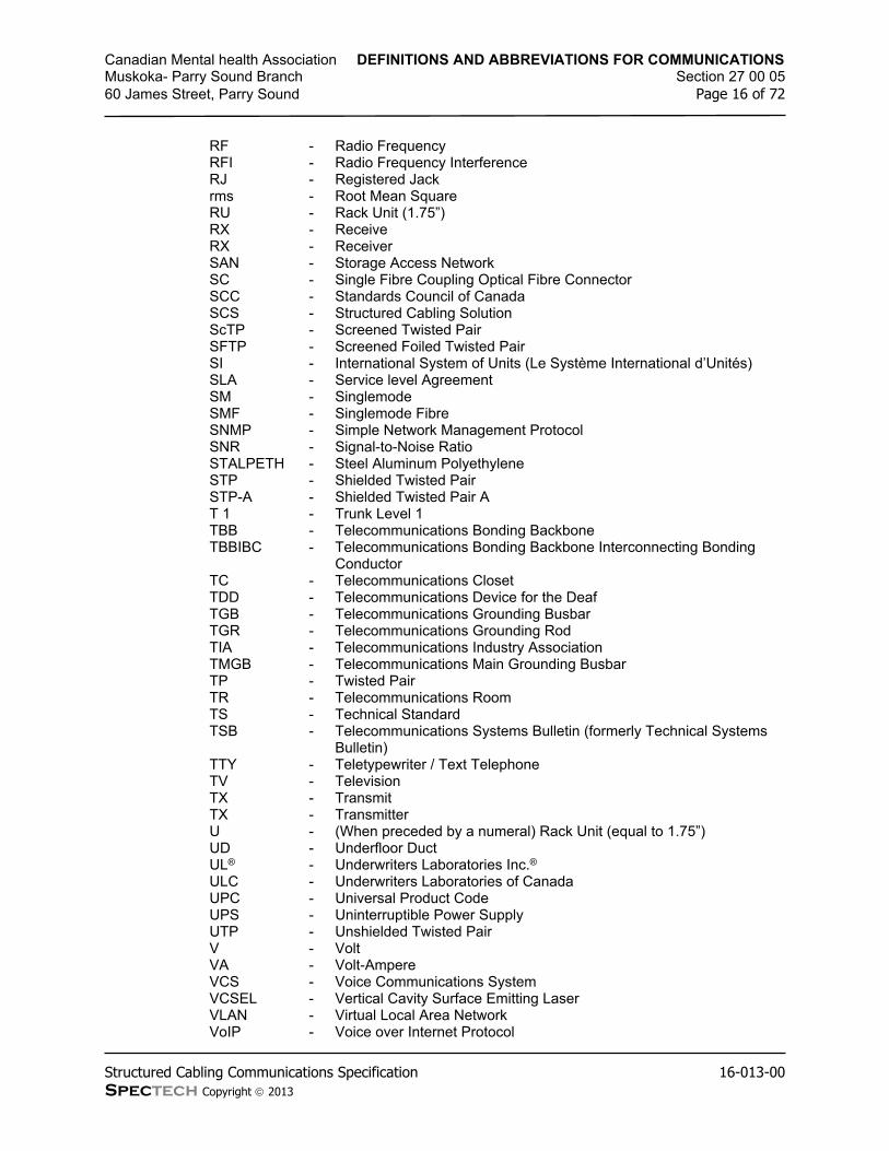
Canadian Mental health Association DEFINITIONS AND ABBREVIATIONS FOR COMMUNICATIONSMuskoka- Parry Sound Branch Section 27 00 0560 James Street, Parry Sound Page 16 of 72
Structured Cabling Communications Specification 16-013-00Spectech Copyright 2013
RF - Radio FrequencyRFI - Radio Frequency InterferenceRJ - Registered Jackrms - Root Mean SquareRU - Rack Unit (1.75”)RX - ReceiveRX - ReceiverSAN - Storage Access NetworkSC - Single Fibre Coupling Optical Fibre ConnectorSCC - Standards Council of CanadaSCS - Structured Cabling SolutionScTP - Screened Twisted PairSFTP - Screened Foiled Twisted PairSI - International System of Units (Le Système International d’Unités)SLA - Service level AgreementSM - SinglemodeSMF - Singlemode FibreSNMP - Simple Network Management ProtocolSNR - Signal-to-Noise RatioSTALPETH - Steel Aluminum PolyethyleneSTP - Shielded Twisted PairSTP-A - Shielded Twisted Pair AT 1 - Trunk Level 1TBB - Telecommunications Bonding BackboneTBBIBC - Telecommunications Bonding Backbone Interconnecting Bonding
ConductorTC - Telecommunications ClosetTDD - Telecommunications Device for the DeafTGB - Telecommunications Grounding BusbarTGR - Telecommunications Grounding RodTIA - Telecommunications Industry AssociationTMGB - Telecommunications Main Grounding BusbarTP - Twisted PairTR - Telecommunications RoomTS - Technical StandardTSB - Telecommunications Systems Bulletin (formerly Technical Systems
Bulletin)TTY - Teletypewriter / Text TelephoneTV - TelevisionTX - TransmitTX - TransmitterU - (When preceded by a numeral) Rack Unit (equal to 1.75”)UD - Underfloor DuctUL® - Underwriters Laboratories Inc.®ULC - Underwriters Laboratories of CanadaUPC - Universal Product CodeUPS - Uninterruptible Power SupplyUTP - Unshielded Twisted PairV - VoltVA - Volt-AmpereVCS - Voice Communications SystemVCSEL - Vertical Cavity Surface Emitting LaserVLAN - Virtual Local Area NetworkVoIP - Voice over Internet Protocol

Canadian Mental health Association DEFINITIONS AND ABBREVIATIONS FOR COMMUNICATIONSMuskoka- Parry Sound Branch Section 27 00 0560 James Street, Parry Sound Page 17 of 72
Structured Cabling Communications Specification 16-013-00Spectech Copyright 2013
VPN - Virtual Private NetworkW - WattWAN - Wide Area NetworkWAP - Wireless Application ProtocolWi-Fi - Wireless FidelityWi-Fi - Wireless FidelityWLAN - Wireless Local Area NetworkWMAN - Wireless Metropolitan Area NetworkWS - WorkstationWWAN - Wireless Wide Area Networkx - Mathematical Operation (Multiplication)X - Cross-connectXC - Cross-connectXLPE - Cross-linked PolyethyleneXPE-PVC - Expanded Polyethylene Polyvinyl Chloride
2 Product
2.1 Not applicable to this Section.
3 Execution
3.1 Not applicable to this Section.
END OF SECTION

Canadian Mental health Association CODES AND STANDARDS FOR COMMUNICATIONSMuskoka- Parry Sound Branch Section 27 00 0760 James Street, Parry Sound Page 18 of 72
Structured Cabling Communications Specification 16-013-00Spectech Copyright 2013
1 General
1.1 Work Included
Comply with Section 27 00 03 – General Specifications and Requirements for Communications.
1.2 General
.1 The Communications Contractor shall adhere to all applicable codes, standards and regulations.
.2 All equipment, products and installation methods shall adhere to all Codes and Standards having jurisdiction and as listed in this document.
.3 The latest version, including technical bulletins and addenda will be applicable to all codes and standards.
.4 If a conflict between codes and standards occur the most stringent code or standard will be applicable.
.5 The following list highlights the typical applicable standards. All national and local codes and standards not listed for Products, Buildings, Fire, Health and Safety and Electrical will also apply.
ANSI/TIA/EIA 568-B.1 - Commercial Building Telecommunications Cabling Standard: General Requirements
ANSI/TIA/EIA 568-B.2 - Commercial Building Telecommunications Cabling Standard: Balanced Twisted Pair Cabling
ANSI/TIA/EIA 568-B.3 - Commercial Building Telecommunications Cabling Standard: Optical Fibre Cabling Components Standard
ANSI/TIA/EIA 569-A - Commercial Building Standards for Telecommunications Pathways and Spaces. Including Addenda 1-6
ANSI/TIA/EIA 598-A - Optical Fibre Cable Color CodingANSI/TIA/EIA 570 - Residential and Light Commercial
Telecommunications Wiring StandardANSI/TIA/EIA 604 - Fibre Optic Connector Intermateability Standard
(Focis3)ANSI/TIA/EIA 606 - Administration Standard for the Telecommunications
Infrastructure of Commercial BuildingsANSI/TIA/EIA 607 - Commercial Building Grounding and Bonding
Requirements for TelecommunicationsANSI/TIA/EIA 758 - Customer Owned Outside Plant Telecommunications
Cabling StandardCSA C22.1-98 - Canadian Electric Code Part I: Safety Standards for
Electrical InstallationsCSA C22.2 No. 181.4 - Plugs, Receptacles, and Connectors for
Communication SystemsCSA C22.2 No. 214 - Communications CablesCSA C22.2 No. 0 - Canadian Electric Code Part II: General
Requirements (Communications Cables)CSA C22.2 232 M1998 - Canadian Electric Code Part II: Optical Fibre CablesCSA T527 - Grounding and Bonding for Telecommunications in

Canadian Mental health Association CODES AND STANDARDS FOR COMMUNICATIONSMuskoka- Parry Sound Branch Section 27 00 0760 James Street, Parry Sound Page 19 of 72
Structured Cabling Communications Specification 16-013-00Spectech Copyright 2013
Commercial BuildingsCSA T528 - Design Guidelines for Administration of
Telecommunications Infrastructure in Commercial Buildings
CSA T529 - Design Guidelines for Telecommunications Wiring Systems in Commercial Buildings
CSA T530 - Building Facilities, Design Guidelines for Telecommunications
BICSI ITSIM - Information Transport System Installation ManualCAN/ULC S115 - Standard Method of Fire Tests of Fire stop SystemsCAN/ULC S101 - Standard Method of Fire Endurance Tests of Building
Construction and MaterialsCAN/ULC S102 - Standard Method of Testing for Surface Burning
Characteristics of Building Materials and AssembliesJ-STD-607 - Commercial Building Grounding (Earthing) and
Bonding Requirements for TelecommunicationsTIA-222 - Structural Standards for Steel Antenna Towers and
Antenna Supporting StructuresTIA-942 - Telecommunications Infrastructure Standards for
Data CentersCEC, Part 1 - The Canadian Electrical Code, Part 1OESC - Ontario Electrical Safety Code – 25th Edition/2012O.R. 388/97 - Ontario Fire CodeO.R. 332/12 - Ontario Building Code 2012IEEE 802.3 - Information Technology – Telecommunications and
Information Exchange Between Systems – Local and Metropolitan Area Networks p Specific Requirements Part 3 Carrier Sense Multiple Access with Collision
IEEE 802.11 - Local and Metropolitan Area Networks – Specific Requirements Part 11: Wireless LAN Medium Access Control and Physical Specifications
ANSI/ICEA S-80-576 - Communication CablesANSI/ICEA S-83-596 - Fibre Optic Premises Distribution CableANSI/ICEA S-83-640 - Fibre Optic Outside Plant Communications CableANSI/ICEA Z136.2 - American Standards for the Safe Operation of Optical
Fibre Communication Systems Utilizing Laser Diode and LED Sources
ANSI/TIA/EIA 455 - Fibre Optic Test ProceduresANSI/TIA/EIA 492AAAA - Detail Specification for 62.5-mm Core Diameter/125-
mm Cladding Diameter Class Ia Multimode, Graded-Index Optical Waveguide Fibres
ANSI/TIA/EIA 492AAAB - Detail Specification for 50.0-mm Core Diameter/125-mm Cladding Diameter Class Ia Multimode, Graded-Index Optical Waveguide Fibres
ANSI/TIA/EIA 492BAAA - Detail Specification for Class IVa Dispersion-Unshifted Singlemode Optical Waveguide Fibres Used In Communications Systems
ANSI/TIA/EIA 472CAAA - Detail Specification for All-Dielectric (Construction 1) Fibre Optic Communications Cable for Indoor Plenum Use, Containing Class Ia, 62.5 mm Core Diameter/125 Cladding Diameter Optical Fibre(s)
ANSI/TIA/EIA 472DAAA - Detail Specification for All-Dielectric Fibre Optic Communications Cable for Outside Plant Use, Containing Class Ia, 62.5 mm Core Diameter/125 mm

Canadian Mental health Association CODES AND STANDARDS FOR COMMUNICATIONSMuskoka- Parry Sound Branch Section 27 00 0760 James Street, Parry Sound Page 20 of 72
Structured Cabling Communications Specification 16-013-00Spectech Copyright 2013
Cladding Diameter/250 mm Coating Diameter Optical Fibre(s)
ANSI INCITS 263 - Information Technology – Fibre Distributed Data Interface (FDDI) – Token Ring Twisted Pair Physical Layer Medium Dependent (TP-PMD)
CENELEC EN 50173 - Performance Requirements for Generic Cabling Schemes
FIPS PUB 174 - Commercial Building Telecommunications Wiring Standard. Federal Information Publication Standard
ICEA S-90-661 - Individually Unshielded Twisted Pair Indoor Cable for Use in Communications Wiring Systems
IEC 603-7, Part 7 - Detailed Specifications for Connectors, 8-Way, Including Fixed and Free Connectors with Common Mating Schemes
ISO/IEC IS 11801A - Generic Cabling for Customer PremisesNEMA WC 63 - Performance Standard for Field Testing of
Unshielded Twisted-Pair Cabling SystemOHSA - Occupational Health and Safety Act - R.S.O. 1990, c.
0-1UL 444 and 13 - Adopted Test and Follow-Up Service Requirements
For The Optional Qualification of 100Ω Twisted-PairUL 1492 - Standard for Safety Audio-Video Products and
AccessoriesUL 813 - Standard for Commercial Audio EquipmentUL 983 - Standard for Surveillance Camera UnitsUL 1459 - Standard for Telephone EquipmentUL 1950 - Standard for Information Technology EquipmentCEA-CEB19 - Recommended Loudspeaker Safety PracticesCEA-CPEB6-A R-2004 - Preferred Voltage and Impedances Values for the
Interconnection of Audio ProductsCEA-426-B R-2005 (ANSI) - Loudspeaker, Optimum Amplifier PowerNCTA - National Cable Television AssociationNCTA-02/89 rev. 93 - NCTA Recommended Practices for Measurements
on Cable Television Systems
2 Product
2.1 Not applicable to this Section.
3 Execution
3.1 Compliance to Codes and Standards
.1 The Communications Contractor shall install all equipment and material in accordance with the standards aforementioned in this section.
.2 Quality and workmanship shall be at the highest of professional tradesman levels to be accepted for completion. The Technology Systems Consultant shall have the sole right to reject any work not in accordance with industry standards.
.3 All work shall also be performed in accordance with the latest BICSI installation standards.

Canadian Mental health Association CODES AND STANDARDS FOR COMMUNICATIONSMuskoka- Parry Sound Branch Section 27 00 0760 James Street, Parry Sound Page 21 of 72
Structured Cabling Communications Specification 16-013-00Spectech Copyright 2013
.4 Communications Contractors shall provide installers trained in all applicable codes, standards, regulations and installation standards.
END OF SECTION

Canadian Mental health Association SCOPE OF WORK FOR STRUCTURED CABLING COMMUNICATIONSMuskoka- Parry Sound Branch Section 27 00 09.1060 James Street, Parry Sound Page 22 of 72
Structured Cabling Communications Specification 16-013-00Spectech Copyright 2013
1 General
1.1 Work Included
Comply with Section 27 00 03 – General Specifications and Requirements for Communications.
1.2 Acceptable Manufacturers – Copper Cabling
.1 All equipment and products supplied shall be new and free of all manufacturer defects and delivery or installation damage.
.2 All equipment and products supplied shall meet all manufacturer listed characteristics as identified in the latest manufacturer catalogue.
.3 All products shall meet all applicable codes and standards and bare the UL/ULC label, be CSA approved and meet FCC/CRTC Regulations.
.4 All products shall be provided in accordance with local, provincial and national fire ratings for the installation on this project.
.5 The only acceptable Manufacturers of an end to end solution for this project and as further specified in this document will be the following:
BeldenHubbell
.6 Certification
.1 The Owner requires a complete “Permanent Link” tested and certified installation. Certification shall be provided by the specified and selected product manufacturer directly to the Owner for a period no less than 20 years.
.2 The Communications Contractor is responsible for providing to the Technology Systems Consultant a copy of the application for certification with 5 days of project award.
.3 Upon completion of the project the Communications Contractor shall deliver to the Technology Systems Consultant for the Owner a copy of the manufacturer’s warranty information, certificate and or plaque. This information shall accompany the final documentation described further in these specifications.
.4 The Communications Contractor shall currently be an authorized installer of the manufacturer providing the warranty.
Belden Certified Systems VendorHubbell Mission Critical Certified Contractor
.7 Subcontractors shall not be acceptable to provide warranty unless pre-approved by the Technology Systems Consultant and the Owner at time of tender. Subcontractors will not be approved after tender is awarded.
.8 The Communications Contractor shall provide a written 1 year warranty inclusive of all parts and labour for the end to end solution. The Communications Contractor shall also state and agree in writing to providing response for any warranty request within 24 hours during this warranty period.
1.3 Acceptable Manufacturers – Optical Fibre Cabling

Canadian Mental health Association SCOPE OF WORK FOR STRUCTURED CABLING COMMUNICATIONSMuskoka- Parry Sound Branch Section 27 00 09.1060 James Street, Parry Sound Page 23 of 72
Structured Cabling Communications Specification 16-013-00Spectech Copyright 2013
.1 All equipment and products supplied shall be new and free of all manufacturer defects and delivery or installation damage.
.2 All equipment and products supplied shall meet all manufacturer listed characteristics as identified in the latest manufacturer catalogue.
.3 All products shall meet all applicable codes and standards and bare the UL/ULC label, be CSA approved and meet FCC/CRTC Regulations.
.4 All products shall be provided in accordance with local, provincial and national fire ratings for the installation on this project.
.5 The only acceptable Manufacturers of an end to end solution for this project and as further specified in this document will be the following:
BeldenCorningHubbell
.6 Certification
.1 The Owner requires a complete “Permanent Link” tested and certified installation. Certification shall be provided by the specified and selected product manufacturer directly to the Owner for a period no less than 20 years.
.2 The Communications Contractor is responsible for providing to the Technology Systems Consultant a copy of the application for certification with 5 days of project award.
.3 Upon completion of the project the Communications Contractor shall deliver to the Technology Systems Consultant for the Owner a copy of the manufacturer’s warranty information, certificate and or plaque. This information shall accompany the final documentation described further in these specifications.
.4 The Communications Contractor shall currently be an authorized installer of the manufacturer providing the warranty.
Belden Certified Systems VendorCorning Network of Preferred Installers (NPI)Hubbell Mission Critical Certified Contractor
.7 Subcontractors shall not be acceptable to provide warranty unless pre-approved by the Technology Systems Consultant and the Owner at time of tender. Subcontractors will not be approved after tender is awarded.
.8 The Communications Contractor shall provide a written 1 year warranty inclusive of all parts and labour for the end to end solution. The Communications Contractor shall also state and agree in writing to providing response for any warranty request within 24 hours during this warranty period.
2 Product
2.1 Not applicable to this Section.
3 Execution

Canadian Mental health Association SCOPE OF WORK FOR STRUCTURED CABLING COMMUNICATIONSMuskoka- Parry Sound Branch Section 27 00 09.1060 James Street, Parry Sound Page 24 of 72
Structured Cabling Communications Specification 16-013-00Spectech Copyright 2013
3.1 Scope
.1 The project consists of the fit-out of the (2) floors, CHMA, located at 60 James Street in the city of Parry Sound.
.2 The specific structured cabling system scope of this project includes but is not limited to:
.1 Supply of five bound copies of shop drawings for all products prior to placing material order to acquire written approval from the Technology Systems Consultant.
.2 Supply and installation of J-hook and cable sling pathways as indicated in this specification.
.3 Supply and installation of 4-pair UTP horizontal copper cabling and related accessories to support end-user data applications.
.4 Supply and installation of 4-pair UTP horizontal copper cabling and related accessories to support end-user voice applications.
.5 Supply and installation of multipair copper cabling and related accessories to support data and/or voice applications over backbone.
.6 Supply and installation of optical fibre cabling and related accessories to support data and/or voice applications over backbone.
.7 Supply and installation of innerduct for optical fibre cabling.
.8 Supply and installation of new open racks, equipment and accessories.
.9 Supply and installation of backboards.
.10 Supply and installation of all fire stop materials and/or mechanisms for all penetrations used for communications cabling.
.11 Complete testing of each cable in a timely fashion and in coordination with other trades and services to ensure a completely tested system prior to activation by the Owner.
.12 Supply temporary and final record drawings as specified.
.13 Complete all final documentation requirements including documentation and site reviews to provide manufacturer’s certification as per Section 27 00 11.
3.2 Phasing
.1 This project shall be completed in (1) one phase. Co-ordination with the Owners staff (including but not limited to the IT staff) and other trades is imperative and shall form part of the scope of this project. This installation will not necessarily be completed over a continuous time period and may be completed over two or more time periods to allow for co-ordination with other groups / trades.
END OF SECTION

Canadian Mental health Association ADMINISTRATIVE REQUIREMENTS FOR COMMUNICATIONSMuskoka- Parry Sound Branch Section 27 00 1160 James Street, Parry Sound Page 25 of 72
Structured Cabling Communications Specification 16-013-00Spectech Copyright 2013
1 General
1.1 Work Included
.1 Comply with Section 27 00 03 – General Specifications and Requirements for Communications.
1.2 Shop Drawings
.1 Provide 5 copies of manufacturer prepared shop drawings identifying complete technical specifications for each product being supplied as part of the end to end solution including fire stopping, pathways and other miscellaneous products.
.2 Shop drawings shall be stamped and signed “For Review” complete with date submitted.
.3 Manufacturers shop drawings showing various model or styles shall be labelled with identification arrows showing which items are being proposed. Arrows shall be reproducible through standard photocopying.
.4 Shop drawings shall be approved by the Technology Systems Consultant prior to starting installation and the Communications Contractor will be responsible for the cost of replacing of all installed product not approved.
.5 Approved shop drawings shall be included in the Project Manual for this project.
1.3 Project Documentation
.1 The Communications Contractor shall provide hand marked record drawings showing all cable numbers on floor plans, rack elevations, backboard layouts and cable routing at the completion of the project. Drawings shall include all architectural and project changes. Provide within ten (10) days of completion of the project two (2) hard copies for use by the Technology Systems Consultant.
.2 The Communications Contractor shall include an allowance of $ 1,000 to be paid to the Technology Systems Consultant for the preparation of final record drawings and coordination of record documentation. The Technology Systems Consultant will coordinate and provide final delivery of record documentation to the Owner upon receipt of payment from the Communications Contractor.
.3 Prepare a complete test report for each cable identifying a successful test on each cable, complete with the technician’s signature and date. Test reports shall be full test reports in the testing software format and with one page per cable. Provide 1 soft copy on CD of test results with appropriate viewing software to the Technology Systems Consultant within ten (10) days of project completion for approval.
.4 At the completion of the project be prepared to submit 1 copy of a project manual in a 3 ring binder to the Technology Systems Consultants for review and approval. This project manual shall include:
.1 Contractor’s Name, contact information and lead installer/foreman’s contact info
.2 Letter detailing, total cost of project (including changes), square footage, number of cable drops, project highlights, Architect/Interior Designer and Owner name and contact information.
.3 Final bill of materials

Canadian Mental health Association ADMINISTRATIVE REQUIREMENTS FOR COMMUNICATIONSMuskoka- Parry Sound Branch Section 27 00 1160 James Street, Parry Sound Page 26 of 72
Structured Cabling Communications Specification 16-013-00Spectech Copyright 2013
.4 Approved shop drawings
.5 WIMS data sheets on all applicable materials including fire stopping
.6 Maintenance and/or operation manuals for all equipment
.7 Test results
.8 Record drawings
.9 Letter of 1 year installation warranty
.10 Manufacturer’s Certification and warranty documentation
.11 Upon written approval from the Technology Systems Consultant prepare (3) additional project manuals for distribution to the Owner.
.12 The Communications Contractor shall prepare a separate Data and Voice Connectivity Database in MS Excel spreadsheet format that includes but not limited to the following:
.13 Data - Horizontal cable number, active equipment port, backbone cable/strand and Owner assigned designation.
.14 Voice - Horizontal cable number, backbone pair, Telephone Switch/Node (TN) and Owner assigned designation.
.15 Provide (1) hard copy and (1) soft copy for the Owners use prior to move in.
.5 Final documentation not provided within 30 days of project completion and with reasonable notification may result in the commissioning of another agent to prepare such documents. Costs for this work will be deducted from all Holdback amounts available to the Communications Contractor.
1.4 Site Documentation
.1 The Communications Contractor shall be responsible for maintaining a complete set of record marked up drawings on site for the Technology Systems Consultants review at all times. Drawings shall be up to date with all architectural and project changes.
.2 Maintain a log of date, time and reason for any delays in performing the installation. Details shall include names, conditions and specific reason for delay.
2 Product
2.1 Documentation Requirements
.1 The following items shall be delivered as scheduled after project award:
Delivery Item Delivery Schedule Presentation
Connectivity Diagrams (PDF) 10 days after project award EmailShop Drawings (PDF) 10 days after project award Email
Monthly Draw Breakdown (PDF) 10 days after project award Email
.2 The following items shall be kept up to date during project construction.
Delivery Item Delivery Schedule Presentation

Canadian Mental health Association ADMINISTRATIVE REQUIREMENTS FOR COMMUNICATIONSMuskoka- Parry Sound Branch Section 27 00 1160 James Street, Parry Sound Page 27 of 72
Structured Cabling Communications Specification 16-013-00Spectech Copyright 2013
Continuously Updated Drawings During construction on-site DVD
.3 The following items shall be delivered after project completion in a binder:
Delivery Item Delivery Schedule Presentation
Contractor’s Information 10 Days after Cutover DVDProject Details 10 Days after Cutover DVDFinal Bill of Materials 10 Days after Cutover DVDApproved Shop Drawings 10 Days after Cutover DVDWIMS Data Sheets 10 Days after Cutover DVDMaintenance / operation manuals 10 Days after Cutover DVDRecord Test Results 10 Days after Cutover DVDRecord Drawings (PDF) 10 Days after Cutover DVDContractor’s 1 Year Warranty 10 Days after Cutover DVDManufacturer Warranty 10 Days after Cutover DVDProgramming 10 Days after Cutover DVD
.4 Should the Owner or General Contractor require hardcopies of any documents listed here as to be provided in an electronic format, the Communications Contractor shall provide as requested at no additional cost.
3 Execution
3.1 Not applicable to this Section.
END OF SECTION

Canadian Mental health Association FIRE STOPPING FOR COMMUNICATIONSMuskoka- Parry Sound Branch Section 27 00 1360 James Street, Parry Sound Page 28 of 72
Structured Cabling Communications Specification 16-013-00Spectech Copyright 2013
1 General
1.1 Work Included
.1 Comply with Section 27 00 03 – General Specifications and Requirements for Communications.
1.2 General
.1 Use only fire stopping products that have been tested for specific fire resistance rated construction conditions conforming to construction assembly type, penetrating item type, annular space requirements, and fire rating involved for each separate instance.
1.3 Materials
.1 Products manufactured by Specified Technologies Inc. (STI) or equivalent are acceptable.
.2 Obtain fire stop systems for each type of penetration and construction condition indicated from a single manufacturer (i.e. Do not mix manufacturers for the same type of penetration).
1.4 Performance Requirements
.1 Fire Stop Systems shall conform to the fire (F), hose (H) and temperature (T) ratings of Codes and shall have a flame spread rating of 25 or less, National Fire Protection Association (NFPA Class "A").
.2 Fire Stop Systems acceptable for this project are those that have been tested to the CAN/ULC S115 Standard.
.3 Fire Stop Systems shall be CSA approved, non-permanent, dielectric, water resistant, non-hardening, permanently pliable/re-enterable putty along with the appropriate damming or backer materials.
.4 Fire stopping shall maintain a minimum one hour rating, meet applicable Federal, Provincial, Local building codes and be tested by a SCC and accredited Third Party Testing Agency in accordance with the Standards.
.5 In locations containing high moisture, fire stopping shall be compatible with Formalin.
.6 Fire rated fittings allowing easy cable additions may be used. All non-permanent caulking or foams shall be replaced with the removal or addition of any cabling before final acceptance by the owner.
.7 Fire rated pathway devices shall be the preferred product and shall be installed in all locations where frequent cable moves, add-ons and changes will occur.
.8 Where non-mechanical products are utilized, provide products that upon curing do no re-emulsify, dissolve, leach, breakdown or otherwise deteriorate over time from exposure to atmospheric moisture, sweating pipes, ponding water or other forms of moisture characteristic during or after construction.
.9 Where it is not practical to use a mechanical device, openings within floors and walls designed to accommodate communications cabling shall be provided with re-enterable products that do not cure or dry.
.10 Openings for cable trays shall be sealed using re-enterable fire stopping pillows.

Canadian Mental health Association FIRE STOPPING FOR COMMUNICATIONSMuskoka- Parry Sound Branch Section 27 00 1360 James Street, Parry Sound Page 29 of 72
Structured Cabling Communications Specification 16-013-00Spectech Copyright 2013
1.5 Quality Assurance
.1 Products/Systems: Provide fire stopping systems that comply with the following requirements:
.1 Fire stopping tests are performed by a qualified, testing and inspection agency. A qualified testing and inspection agency is UL, or another agency performing testing and follow-up inspection services for fire stop system acceptable to authorities having jurisdiction.
.2 Fire stopping products bear the classification marking of qualified testing and inspection agency.
.2 Installer Qualifications: Experience in performing work of this section who is qualified by the fire stopping manufacturer as having been provided the necessary training to install fire stop products in accordance with specified requirements.
1.6 Delivery, Storage and Handling
.1 Manufacturer’s original, unopened, undamaged containers, identification labels intact identifying product and manufacturer, date of manufacture; lot number; shelf life, if applicable; qualified testing and inspection agency’s classification marking; and mixing instruction for multicomponent products.
.2 Handle and store products according to manufacturer’s recommendations published in technical materials. Leave products wrapped or otherwise protected and under clean and dry storage conditions until required for installation.
.3 Store materials protected from exposure to harmful weather conditions and at temperature and humidity conditions recommended by manufacturer.
1.7 Project Conditions
.1 Do not install fire stopping products when ambient or substrate temperatures are outside limitations recommended by manufacturer.
.2 Do not install fire stopping products when substrates are wet due to rain, frost, condensation, or other causes.
.3 Maintain minimum temperature before, during, and for a minimum 3 days after installation of materials.
.4 Do not use materials that contain flammable solvents.
.5 Coordinate construction of openings and penetrating items to ensure that through-penetration fire stop systems are installed according to specified requirements.
.6 Coordinate sizing of sleeves, openings, core-drilled holes, or cut openings to accommodate through-penetration fire stop systems.
.7 Schedule installation of fire stopping after completion of penetrating item installation but prior to covering or concealing of openings.
.8 Supply and install temporary fire stopping at the end of every work shift or when location of work is changing from one work area to another. This shall be done to maintain the penetration’s fire rating in areas where no work is being done.
2 Product

Canadian Mental health Association FIRE STOPPING FOR COMMUNICATIONSMuskoka- Parry Sound Branch Section 27 00 1360 James Street, Parry Sound Page 30 of 72
Structured Cabling Communications Specification 16-013-00Spectech Copyright 2013
2.1 Fire Stop Grommets
.1 STI SpecSeal Brand molded two-piece grommet having a foam fire and smoke sealing membrane that conforms to the outside diameter of the individual cable.
.2 Shall be used only for penetrations of only 1 (one) or 2 (two) 4-pair UTP or F/STP cables.
Specified Product:Part No. # of Cables Hole Diameter
Specified Technologies Inc. (STI) RFG1 1 9/16” (14mm)Specified Technologies Inc. (STI) RFG2 2 1” (25mm)
2.2 Fire Stop Sealants
.1 STI SpecSeal® Brand single component latex formulations that upon cure do not re-emulsify during exposure to moisture.
Specified Product:Specified Technologies Inc. (STI) SpecSeal® Series SSS SealantSpecified Technologies Inc. (STI) SpecSeal® Series LCI Sealant
2.3 Fire Stop Putty
.1 STI SpecSeal® Brand intumescent, non-hardening, water resistant putties containing no solvents, inorganic fibres or silicone compounds.
Specified Product:Specified Technologies Inc. (STI) SpecSeal® Series SSP Putty
2.4 Fire Stop Pillows
.1 STI SpecSeal® Brand re-enterable, non-curing, mineral fibre core encapsulated on six sides with intumescent coating contained in a flame retardant poly bag.
Specified Product:Specified Technologies Inc. (STI) SpecSeal® Series SSB Pillows
2.5 Fire Rated Cable Pathways
.1 STI EZ-PATH™ Brand device modules comprised of steel raceway with intumescent foam pads allowing 0 to 100 percent cable fill.
Specified Product:EZ-Path Multi-Gang Wall Bracket EZP544WEZ-Path (No Options) EZD44Single EZ-Path Kit EZDP44
Only where wall thickness exceeds 10” use the following (adjust quantity of EZ-Path units and accessories to suit cable quantity):Single EZ-PATH Kit EZDP33FWSTwo Gang EZ-PATH Kit EZDP233GKThree Gang EZ-PATH Kit EZDP333GKFour Gang EZ-PATH Kit EZDP433GKRadius Control Module RCM33Extension Module EZD33E
3 Execution

Canadian Mental health Association FIRE STOPPING FOR COMMUNICATIONSMuskoka- Parry Sound Branch Section 27 00 1360 James Street, Parry Sound Page 31 of 72
Structured Cabling Communications Specification 16-013-00Spectech Copyright 2013
3.1 Examination
.1 Before beginning installation, verify that substrate conditions previously installed under other sections are acceptable for installation of fire stopping in accordance with manufacturer’s installation instructions and technical information.
.2 Surfaces shall be free of dirt, grease, oil, scale, laitance, rust, release agents, water repellents, and any other substances that may inhibit optimum adhesion.
.3 Provide masking and temporary covering to protect adjacent surfaces.
.4 Do not proceed until unsatisfactory conditions have been corrected.
3.2 Installation
.1 Install through-penetration fire stop systems in accordance with Performance Criteria and in accordance with the conditions of testing and classification as specified in the published design.
.2 Comply with manufacturer’s instructions for installation of fire stopping products.
3.3 Field Quality Control
.1 Keep areas of work accessible until inspection by authorities having jurisdiction.
.2 Where deficiencies are found, repair fire stopping products so they comply with requirements.
3.4 Non-Monitored Penetrations
.1 Where fire watch is not in effect, or the Communications Contractor has not been able to confirm whether fire watch is in effect, all fire penetrations, whether all cables have been pulled or not, removed or not, shall be fire stopped at the end of every workday prior to the Communications Contractor leaving the site. At no time shall a penetration be un-attended or without fire stopping material in areas where work is not in progress.
END OF SECTION

Canadian Mental health Association GROUNDING AND BONDING FOR COMMUNICATIONSMuskoka- Parry Sound Branch Section 27 05 2660 James Street, Parry Sound Page 32 of 72
Structured Cabling Communications Specification 16-013-00Spectech Copyright 2013
1 General
1.1 Work Included
.1 Comply with Section 27 00 03 – General Specifications and Requirements for Communications.
1.2 General
.1 All cables and related terminations, support and grounding hardware shall be furnished, installed, wired, tested, labelled, and documented by the Communications Contractor as detailed in this section.
.2 Product specifications, general design considerations and installation guidelines are provided in this section.
.3 The Communications Contractor shall meet or exceed all requirements for the cable system described in this section.
.4 Local electrical codes shall be adhered to.
.5 Local building codes shall be adhered to.
.6 All communications components including, entrance lugs, entrance terminal frames, racks, cabinets, cable tray, ladder racks, metallic pathways, enclosures and other components noted on drawings shall be bonded to an independent grounding system and in accordance with local codes and standards, TIA/EIA J-STD-607-A, ANSI/TIA-942 and IEEE Std.1100 and these specifications.
.7 Labelling shall conform to TIA/EIA-606.
.8 Grounding system shall include a local copper Telecommunications Grounding Busbar (by Division 26) in each entrance facility and equipment room bonded to a Telecommunications Grounding Backbone (by Division 26).
.9 The TBB shall be bonded directly to the Telecommunications Main Grounding Busbar (by Division 26). The TMGB shall be bonded directly to the building entrance grounding system and meet all local codes and standards as noted above.
.10 The grounding system shall be visually verifiable and adequately sized to handle expected currents safely.
.11 All grounding conductors and busbars shall be made of copper.
.12 The grounding system shall be intentional, visually verifiable, adequately sized to handle expected currents safely, and direct these currents away from network equipment. As such, grounding shall be purposeful in its design and installation.
.13 Lugs, HTAPs, grounding strips, and busbars shall be UL Listed and CSA certified and made of premium quality tin-plated electrolytic copper that provides low electrical resistance while inhibiting corrosion. Antioxidant shall be used when making bonding connections in the field.
1.3 Lugs
.1 Wherever possible, two-hole lugs shall be used. All lugs shall be irreversible compression. Lugs with inspection windows shall be used in all non-corrosive

Canadian Mental health Association GROUNDING AND BONDING FOR COMMUNICATIONSMuskoka- Parry Sound Branch Section 27 05 2660 James Street, Parry Sound Page 33 of 72
Structured Cabling Communications Specification 16-013-00Spectech Copyright 2013
environments so that connections may be inspected for full conductor insertion (battery rooms are an exception where windowless lugs may be used).
.2 Die index numbers shall be embossed on all compression connections to allow crimp inspection.
1.4 Cable Assemblies
.1 Cable assemblies shall be UL Listed and CSA Certified. Cables shall be a distinctive green or green/yellow in color, and all jackets shall be UL, VW-1 flame rated.
1.5 Telecommunications Grounding Busbar
.1 The Telecommunications Grounding Busbar (TGB) shall be supplied and installed by Division 26.
1.6 Telecommunications Bonding Backbone Requirements
.1 The Telecommunications Grounding Busbar within each telecommunications space shall be bonded to the building ground riser with a Telecommunications Bonding Backbone. The TGB and the TBB shall be supplied and installed by Division 26.
.2 The gauge of the TBB shall be determined based on TIA/EIA J-STD-607-A. The table below is shown for reference.
TBB Length in Linear meters (feet) TBB Size (AWG)
Less than 4 (13) 64-6 (14-20) 46-8 (21-26) 38-10 (27-33) 210-13 (34-41) 113-16 (42-52) 1/016-20 (53-66) 2/0
Greater than 20 (66) 3/0
2 Product
2.1 Common Bonding Network
.1 The Common Bonding Conductor within each Entrance Facility, Data Centre, Computer Room, Telecommunications Room, LAN Room, etc. shall be a green or green/yellow jacketed #2 copper conductor. The installation route shall be as shown on drawings.
.2 The Common Bonding Conductor shall be routed in as straight a path as possible.
2.2 Grounding Clamps
.1 Where a grounding conductor is routed through a metal conduit, the Communications Contractor shall use a #6 AWG copper conductor with green or green/yellow jacket to bond the conduit to the grounding conductor routed through the metal conduit. Series GPL grounding clamps shall be used to bond to the conduit and series HTWC HTAP with clear cover shall be used to bond to the grounding conductor.
2.3 Communications Grounding and Bonding Conductor Label Kit

Canadian Mental health Association GROUNDING AND BONDING FOR COMMUNICATIONSMuskoka- Parry Sound Branch Section 27 05 2660 James Street, Parry Sound Page 34 of 72
Structured Cabling Communications Specification 16-013-00Spectech Copyright 2013
.1 Telecommunications Grounding and Bonding Conductor Label Kits shall be supplied and installed by the Communications Contractor at every rack and cabinet as well as one for every Telecommunications Grounding Busbar.
Specified Product:Harger GRNTAG607PK10Panduit LTYK
2.4 Code Conductor, Two-Hole, Long Barrel With Window Lug
.1 Where lugs are required for bonding, the Communications Contractor shall supply and install Code Conductor, Two-Hole, and Long Barrel with Window Lugs.
.2 Code Conductor, Two-Hole, Long Barrel with Window Lugs shall be supplied and installed by the Communications Contractor as required.
.3 Lugs shall be tin plated, irreversible compression, have NEMA hole sizes and spacing and shall meet NEBS Level 3.
2.5 Code/Flex Conductor HTAP
.1 Code/Flex Conductor HTAPs shall be supplied and installed by the Communications Contractor as required.
2.6 Clear Covers for HTCT HTAP
.1 Clear Covers for HTCT HTAPs shall be supplied and installed by the Communications Contractor (each HTAP requires one clear cover).
2.7 Grounding Clamp, U-Bolt, Bronze
.1 Each conduit entering/leaving a telecommunications space/room shall be bonded to the grounding system using a Series GPL Bronze U-Bolt Grounding Clamp.
2.8 Ladder Tray / Basket Tray Grounding
.1 Bonding network jumpers shall be supplied and installed by the Communications Contractor to bond the tray to the grounding system.
2.9 Antioxidant
.1 Antioxidant shall be used by the Communications Contractor when making bonding connections.
2.10 Bonding Screws
.1 Bonding screws shall have serrations on the bottom of screw to remove paint from patch panel to bond patch panel to rack or cabinet rails.
.2 Bonding screws shall be thread-forming to remove paint from threaded rack or cabinet rail holes to bond patch panel to rack or cabinet rails.
.3 The Communications Contractor shall supply and install four (4) screws for every patch panel (copper and optical fibre) as well as for every Owner supplied switch (assume 48 port switches).
Specified Product:Panduit RGTBSG-C #12-24 screwsPanduit RGTBS1032G- #10-32 screws

Canadian Mental health Association GROUNDING AND BONDING FOR COMMUNICATIONSMuskoka- Parry Sound Branch Section 27 05 2660 James Street, Parry Sound Page 35 of 72
Structured Cabling Communications Specification 16-013-00Spectech Copyright 2013
CPanduit RGTBSM6G-C M6 screwsPanduit RGTBSM5G-C M5 screws
2.11 Bonding Cage Nut
Specified Product:Panduit CNB4K
2.12 Bond Clamp
Specified Product:Belden X9905753 For 0.75” or larger cablesBelden X9905754 For 0.75” or smaller cablesBelden AX100226 Six-Position Ground Bracket
2.13 Rack Grounding
.1 Paint Piercing Washers
.1 Series RGW paint piercing washers shall accommodate 3/8” stud size and shall have an outside diameter of 0.875”.
.2 Series RGW paint piercing washer kits shall come complete with 0.16 oz. (5cc) of antioxidant.
.3 Series RGW paint piercing washers shall be supplied and installed by the Communications Contractor where rack elements bolt together.
.4 Series RGW paint piercing washers shall be supplied and installed by the Communications Contractor where vertical cable managers are manufactured of metal.
.5 Two paint piercing washers shall be supplied and installed by the Communications Contractor for every nut/bolt set.
Specified Product:Panduit RGW-24-1Y Pack of 24Panduit RGW-100-1Y Pack of 100
2.14 Rack Grounding Strip
.1 Series RGS grounding strip shall be 78.65” long, 0.67” wide, 0.05” thick, have EIA Universal mounting hole pattern and shall be made of high conductivity, low resistance wrought copper and tin plated.
.2 Series RGS grounding strip kits shall come complete with 0.16 oz. (5cc) of antioxidant and thread-forming screws.
.3 One series RGS rack grounding strip shall be supplied by the Communications Contractor for every two post rack. The rack grounding strip shall be mounted to the rear of the side rail of each rack.
Specified Product:Harger RGBVKIT145872A

Canadian Mental health Association GROUNDING AND BONDING FOR COMMUNICATIONSMuskoka- Parry Sound Branch Section 27 05 2660 James Street, Parry Sound Page 36 of 72
Structured Cabling Communications Specification 16-013-00Spectech Copyright 2013
Panduit RGS134-1Y
2.15 Common Bonding Network Jumper
.1 The Common Bonding Network Jumper shall be made of #6 AWG green or green/yellow jacketed copper conductor no less than 96” long with one end factory terminated to lug.
.2 The Common Bonding Network Jumper kits shall come complete with 0.16 oz. (5cc) of antioxidant and thread-forming screws.
.3 One Common Bonding Network Jumper shall be supplied and installed for every rack. Do not bond racks serially.
Specified Product:Harger RGJ67G1082AKITPanduit RGREJ696Y
.4 Where a Common Bonding Network has not been specified the Communications Contractor shall supply and install a Code Conductor Two Hole Long Barrel with Window Lug to bond the Common Bonding Network Jumper directly to the Telecommunications Grounding Busbar.
Specified Product:Harger GECLB62APanduit LCC6-14JAW-
L
.5 Where a Common Bonding Network has been specified the Communications Contractor shall supply and install a Code/Flex Conductor HTAP or C-TAP Kit to bond the Common Bonding Network Jumper to the Common Bonding Network.
Specified Product:Harger CT2248Panduit HTWC250-2-1
2.16 Electrostatic Discharge Port
.1 The Electrostatic Discharge Port shall accommodate a standard ESD wrist strap 4mm plug.
.2 The Electrostatic Discharge Port kits shall come complete with an ESD protection sticker, 0.16 oz. (5cc) of antioxidant and thread-forming screws.
.3 The Communications Contractor shall supply and install two Electrostatic Discharge Ports for every rack. One ESD port shall be mounted directly to the rack grounding strip on the back of the rack at approximately 48” AFF, and the other shall be mounted directly to the vertical mounting rail of the rack in the front at approximately 48” AFF.
Specified Product:Panduit RGESD2-1 Kit c/w #12-24 and M6 screwsPanduit RGESD2A-1 Kit c/w #10-32 and M5 screws
3 Execution
3.1 General

Canadian Mental health Association GROUNDING AND BONDING FOR COMMUNICATIONSMuskoka- Parry Sound Branch Section 27 05 2660 James Street, Parry Sound Page 37 of 72
Structured Cabling Communications Specification 16-013-00Spectech Copyright 2013
.1 Structured grounding kits shall be TIA-942 compliant, listed for their purpose with a nationally recognized testing laboratory, and RoHS compliant.
.2 Grounding strip shall comply with EIA universal mounting hole spacing and mount to standard 19 inch and 23 inch racks and cabinets.
.3 All components shall be bonded to the rails with paint piercing hardware.
.4 Electrostatic discharge (ESD) ports shall be mounted to the front and back of the rack(s) and/or cabinet(s).
.5 Equipment shall be bonded to the grounding strip with a discrete jumper and two-hole long barrel compression lugs.
.6 There shall be a #6 AWG copper code discrete jumper that terminates on the mesh common bonding network (MCBN) with a compression HTAP and attaches to the grounding strip using a two-hole, long barrel compression lug. The compression lugs shall meet NEBS Level 3 Criteria and have inspection windows.
.7 All jumpers shall have green or green-and-yellow VW-1 rated insulation.
.8 Where rack sections bolt together, paint piercing grounding washers shall be used on both sides, under the head of the bolt and between the nut and the rack.
.9 The Communications Contractor shall ensure a complete grounding system is installed for the project. If any portion of the system to be installed by Division 26 is incomplete it shall be the responsibility of the Communications Contractor to advise the Technology Systems Consultant.
END OF SECTION

Canadian Mental health Association PATHWAYS FOR COMMUNICATIONSMuskoka- Parry Sound Branch Section 27 05 2860 James Street, Parry Sound Page 38 of 72
Structured Cabling Communications Specification 16-013-00Spectech Copyright 2013
1 General
1.1 Work Included
Comply with Section 27 00 03 – General Specifications and Requirements for Communications.
1.2 General
.1 The Communications Contractor shall be responsible for measuring and confirming cable pathways prior to installation of any cabling to ensure no cabling will exceed the specified distance limitations. Where the distance limitations are exceeded, the Communications Contractor shall inform the Technology Systems Consultant prior to installation of cabling. No compensation for removal of cabling will be accepted if not adhered to.
.2 The Communications Contractor shall be responsible for installing and providing pulling strings, ropes and fishing walls wherever conduit is not installed or conduit is installed without these provisions.
1.3 Indoor Cable Distribution
.1 Ensure ANSI/EIA/TIA-568-B installation practices are followed for all indoor cable distribution.
.2 The Communications Contractor shall install and distribute cabling using riser sleeves, conduit, communications cable tray, floor ducts systems and/or surface raceways as indicated on drawings and as supplied and installed by Division 26.
.3 All cabling extending beyond conduit and /or cable tray pathways shall be supported using J-hooks and/or Cable Slings up to the point of termination complete with “Velcro” Ty-raps supplied and installed by the Communications Contractor, in accordance with these specifications.
.4 Innerduct shall be supplied and installed by the Communications Contractor for all fibre optic cabling not indicated shall be installed in conduit and at locations fibre optic cabling leaves a conduit. Innerduct shall be as further described in this specification.
2 Product
2.1 J-Hooks
.1 J-hooks shall be made of metal and/or plastic and shall be Plenum rated.
.2 J-hooks shall be supplied and installed with all necessary fastening suitable for the building structure being used to support the cabling and as per the manufacturer’s installation requirements or guidelines.
.3 J-hooks shall be manufactured by Erico or Panduit and sized to suit.
Specified Product:Erico CAT12Erico CAT21Erico CAT32Erico CAT64Panduit JP75

Canadian Mental health Association PATHWAYS FOR COMMUNICATIONSMuskoka- Parry Sound Branch Section 27 05 2860 James Street, Parry Sound Page 39 of 72
Structured Cabling Communications Specification 16-013-00Spectech Copyright 2013
Panduit JP131Panduit JP2Panduit JP4
Notes: Product Codes shown above indicate only Series numbers and are not application specific.
2.2 Cable Slings
.1 Cable slings shall be supplied and installed as indicated on drawings and as required to support larger bundles of cabling.
.2 Cable slings shall be supplied with all necessary fastening suitable for the building structure being used to support the cabling and as per the manufacturer’s installation requirements or guidelines.
.3 Cable slings shall be manufactured by Erico and sized to suit installation or as noted on drawings.
Specified Product:Erico CAT425
Notes: Product Code shown above indicates only Series number and is not application specific.
2.3 Vertical Backbone Support
.1 Vertical backbone supports shall be supplied and installed as indicated on drawings and as required to support vertically installed backbone.
.2 Vertical backbone supports shall be supplied with all necessary fastening suitable for the building structure being used to support the cabling and as per the manufacturer’s installation requirements or guidelines.
.3 Vertical backbone supports shall be manufactured by Erico and sized to suit installation or as noted on drawings.
Specified Product:Erico CAT600
Notes: Product Code shown above indicates only Series number and is not application specific.
2.4 Velcro Wraps
.1 Velcro wraps shall be supplied and installed to support and neatly bundle all cabling.
.2 No nylon or plastic wraps will be permitted on this project and will be removed and replaced at the expense of the Communications Contractor.
.3 Velcro Wraps shall be black in colour.
Specified Product:Width Tensile Strength
Panduit HLM-15R0 0.330” 18Panduit HLS-15R0 0.750” 50Panduit HLS-75R0 0.750” 50Panduit TTS-20R0 0.750” 40Panduit TTS-35R3-0 0.750” 40

Canadian Mental health Association PATHWAYS FOR COMMUNICATIONSMuskoka- Parry Sound Branch Section 27 05 2860 James Street, Parry Sound Page 40 of 72
Structured Cabling Communications Specification 16-013-00Spectech Copyright 2013
2.5 Innerduct
.1 Innerduct shall be supplied non-plenum (FT4) or plenum (FT6) rated to suit the installation.
.2 All FT6 or CMP rated cabling shall be installed within equally rated innerduct.
.3 All innerduct shall include pre-lubricated pull tape.
.4 Optical fibre cabling may be installed without innerduct where either of the following is true:
.1 The optical fibre cable is armoured.
.2 The conduit where the optical fibre cable(s) will be installed is equal to or less than 1.5” trade size and is dedicated to optical fibre cabling.
.5 Innerduct shall be coloured for use with different cabling as follows:
Multimode Fibre OrangeSinglemode Fibre YellowCopper White or Clear
.6 Innerduct shall be sized to suit or as noted on drawings.
Specified Product:Carlon CF4X1C-500 for PlenumCarlon DF4X1C-500R for Riser
2.6 Split Wrap
.1 Split wrap shall be supplied to dress cabling from wall feed to furniture feed locations.
.2 Split wrap shall be sized to suit each location.
.3 Split wrap shall be coloured to match the power whip supplied with the furniture.
Specified Product:Part Number Tool Required
Panduit PW50F-T20 PWT50Panduit PW75F-C20 PWT75Panduit PW100F-C20 PWT100Panduit PW150F-L20 PWT150
2.7 Overhead Wire Basket Tray
.1 Provide wire basket of types and sizes indicated with all required splicing and mounting hardware.
.2 Wire basket crosswire to be constructed with shaped wire to provide flat surface for cable support, avoiding pressure points or cable strain. Round wire construction shall not be allowed.
.3 Wire basket shall be made of high strength steel wires and formed into a standard 2 inch by 4 inch wire mesh pattern with intersecting wires welded together. All mesh sections must have at least one bottom longitudinal wire along entire length of straight section.
.4 Wire diameter shall be 0.195” (5mm) minimum on all mesh sections up to 16 linear inches. Wire diameter linewire shall be 0.234” (6mm) minimum on all mesh sections in excess of 16 linear inches.
.5 All straight section longitudinal wires shall be constructed with a continuous top wire safety edge. Safety edge must be the WBT “Canadian-Weld” on all tray sizes.

Canadian Mental health Association PATHWAYS FOR COMMUNICATIONSMuskoka- Parry Sound Branch Section 27 05 2860 James Street, Parry Sound Page 41 of 72
Structured Cabling Communications Specification 16-013-00Spectech Copyright 2013
.6 All fittings shall be field formed, from straight sections, in accordance with manufacturer’s instructions.
.7 All Tray sections and splicing assemblies shall be UL/C-UL Classified as an Equipment Ground Conductor (EGC).
.8 The cable tray shall be installed complete with splice bars, “uni-strut” trapeze supports, threaded rod, ceiling anchors and all manufacturer recommended installation components following manufacturer’s installation instructions and recommendations.
Specified Product:Description Part No.
WBT Tray WBT(depth) x (width) x (length)(finish)WBT Cable drop control (“waterfall”) VERTICAL DOWNWBT Bend radius control corner CABLE GUIDEWBT Attachment to fill fitting gap FITTING ATTACHMENT 2WBT Attachment to fill fitting gap FITTING ATTACHMENT 4/6WBT Used to splice tray sections SPLICE KITWBT Used to splice tray sections WASHER SUPPORTWBT Used to splice tray sections BAR SPLICEWBT Used to splice fittings CORNER SPLICEWBT Ceiling support for 12” tray CEILING SUPT 12
3 Execution
3.1 General
.1 All pathways shall be installed to run parallel to building lines at all times.
.2 Pathways shall be installed in coordination with other trades in order to minimize interferences and obstructions. The Communications Contractor shall be responsible for relocating installed pathways at no cost to the Owner.
.3 All cable supports shall be installed to the permanent structure of the building and be limited to areas that will not damage the structural stability such as tensioned beams and slabs. It is the responsibility of the Communications Contractor to submit information to the structural engineer for review and approval prior to installation.
.4 Anchors for J-hooks and/or Cable Slings shall not be drilled into post tensioned beams under any circumstances. All anchors shall be drilled into slab.
.5 Pneumatic hammers shall not be used unless the Communications Contractor has written authorization from the building owner/landlord.
.6 The Communications Contractor shall minimize the removal/disturbance of fire spray insulation while installing cable supports and/or accessories.
3.2 Data and / or Voice Indoor Cable Distribution
.1 All pathways and cabling installation shall maintain clearances from all electrical and heat sources as outlined below.
Fluorescent Fixtures 15 cmElectrical distribution cabling and conduits less than 1KVA 1.0 mElectrical distribution cabling and conduits greater than 1KVA 3.0 mTransformers and Motors 1.2 mHVAC system including ducts 30 cm

Canadian Mental health Association PATHWAYS FOR COMMUNICATIONSMuskoka- Parry Sound Branch Section 27 05 2860 James Street, Parry Sound Page 42 of 72
Structured Cabling Communications Specification 16-013-00Spectech Copyright 2013
Mechanical piping 15 cm
.2 Prepare all conduits and pathways prior to installation of cabling. This shall include bushing or reaming all conduit openings, pulling of wire brush and mandrel to clean out ducts and identifying any potential cause of damage to cabling during installation. Report all items to the Technology Systems Consultant immediately.
.3 When installing cables in stacked duct banks install cabling in lower ducts leaving upper ducts for future installations.
3.3 J-Hooks
.1 Suspended ceiling and T-Bar hangers shall not be acceptable in any situation.
.2 J-Hooks shall be installed every 3’ to 4’ to support cabling (ensure that the distance between j-hooks is not consistent; do not place j-hooks exactly the same distance apart repeatedly).
.3 All cabling shall be installed to have no more than 3” sag between J-hooks. All cabling shall be fastened using Velcro Ty-Wraps only. The Communications Contractor will be responsible for all costs associated with removing other fasteners and install the specified product.
.4 If the quantity of cables exceeds 80% of the manufacturer’s capacity rating install the next larger size or substitute with cable slings at no additional cost to the Owner.
.5 J-hooks shall be installed in coordination with other building services and without interruption to the Owner or surrounding Owners within the building.
3.4 Cable Slings
.1 Cable slings shall be installed as noted on drawings and when cabling exceeds the capacity of J-hooks.
.2 Cable slings shall be installed every 3’ to 4’ to support cabling (ensure that the distance between cable slings is not consistent; do not place cable slings exactly the same distance apart repeatedly).
.3 All cabling shall be installed to have no more than 3” sag between cable slings.
.4 Cable slings shall be sized to not exceed 80% of the manufacturers published capacities.
3.5 Velcro Wraps
.1 Velcro Wraps shall be installed at every J-hook, between every pair of J-hooks or within 2’ of a J-hook to neatly bundle cabling.
.2 Velcro Wraps shall be installed every 3’ to neatly bundle cabling installed in cable tray.
.3 Velcro Wraps shall be installed every 6” to neatly bundle cabling at all locations on racks, cabinets, patch panels and IDC mounts.
3.6 Inner Duct
.1 Innerduct shall be installed and supported to meet all local codes and standards.
.2 Innerduct shall be installed to meet the minimum bend radius for cable installation.
.3 Split Wrap
.4 Split wrap shall be installed to neat bundle cabling from outlet location to system furniture connection point.

Canadian Mental health Association PATHWAYS FOR COMMUNICATIONSMuskoka- Parry Sound Branch Section 27 05 2860 James Street, Parry Sound Page 43 of 72
Structured Cabling Communications Specification 16-013-00Spectech Copyright 2013
.5 Split wrap installation should be in a manner to minimize the amount of exposed spiral wrap.
.6 Secure split wrap neatly when applicable.
3.7 Fire Stopping
.1 For all fire stopping requirements refer to Section 27 00 13 – Fire Stopping for Communications.
3.8 Grounding
.1 For all grounding and bonding requirements refer to Section 27 05 26.10 – Grounding and Bonding for Communications.
END OF SECTION
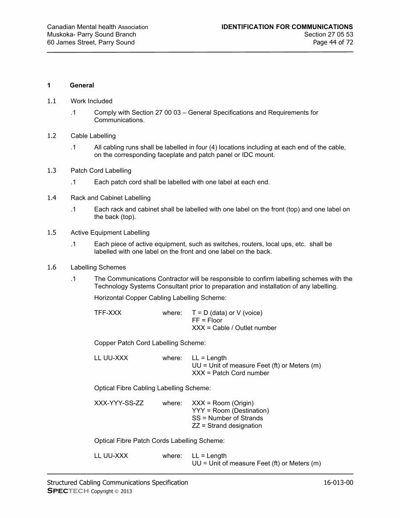
Canadian Mental health Association IDENTIFICATION FOR COMMUNICATIONSMuskoka- Parry Sound Branch Section 27 05 5360 James Street, Parry Sound Page 44 of 72
Structured Cabling Communications Specification 16-013-00Spectech Copyright 2013
1 General
1.1 Work Included
.1 Comply with Section 27 00 03 – General Specifications and Requirements for Communications.
1.2 Cable Labelling
.1 All cabling runs shall be labelled in four (4) locations including at each end of the cable, on the corresponding faceplate and patch panel or IDC mount.
1.3 Patch Cord Labelling
.1 Each patch cord shall be labelled with one label at each end.
1.4 Rack and Cabinet Labelling
.1 Each rack and cabinet shall be labelled with one label on the front (top) and one label on the back (top).
1.5 Active Equipment Labelling
.1 Each piece of active equipment, such as switches, routers, local ups, etc. shall be labelled with one label on the front and one label on the back.
1.6 Labelling Schemes
.1 The Communications Contractor will be responsible to confirm labelling schemes with the Technology Systems Consultant prior to preparation and installation of any labelling.
Horizontal Copper Cabling Labelling Scheme:
TFF-XXX where: T = D (data) or V (voice)FF = FloorXXX = Cable / Outlet number
Copper Patch Cord Labelling Scheme:
LL UU-XXX where: LL = LengthUU = Unit of measure Feet (ft) or Meters (m)XXX = Patch Cord number
Optical Fibre Cabling Labelling Scheme:
XXX-YYY-SS-ZZ where: XXX = Room (Origin)YYY = Room (Destination)SS = Number of StrandsZZ = Strand designation
Optical Fibre Patch Cords Labelling Scheme:
LL UU-XXX where: LL = LengthUU = Unit of measure Feet (ft) or Meters (m)

Canadian Mental health Association IDENTIFICATION FOR COMMUNICATIONSMuskoka- Parry Sound Branch Section 27 05 5360 James Street, Parry Sound Page 45 of 72
Structured Cabling Communications Specification 16-013-00Spectech Copyright 2013
XXX = Patch Cord number
Copper Patch Panel Labelling Scheme:
A where: A = alphabetical character starting with ‘A’
Optical Fibre Patch Panel Labelling Scheme:
A where: A = alphabetical character starting with ‘A’
Rack and Cabinet Labelling Scheme:
RXX where: R = Row (alphabetical character starting with ‘A’)XX = Rack or Cabinet number
2 Product
2.1 Cable, Faceplate, Patch Panel and Active Equipment Labelling
.1 All products shall meet UL 969 standards and be rated for indoor or outdoor use as applicable to the installation.
.2 Cable labels shall be self-laminating, vinyl with white printing area and sized to allow label to wrap around 2.5 times minimum. Labels also shall be sized to suit the labelling requirement maintaining a minimum 10pt. font size.
.3 Faceplate and Patch Panel labels shall be adhesive style made of polyester with a white printing area and sized to suit the designated label location. Labels shall be printed with a minimum 10pt. font size.
.4 Active equipment labels shall be adhesive style made of polyester with a white printing area and sized to suit the designated label location. Labels shall be printed with a minimum ¼” high font.
.5 Patch Panel labels shall be adhesive style made of polyester with a white printing area and sized to suit the designated label location. Labels shall be printed with a minimum ¼” high font.
Specified Product:Cable Dia. RangeInches (cm)
Approx. BreakingStrength Lbs (N)
Hubbell / Bryant 0.75-0.99 (1.90-2.51) 2820 (12543)Hubbell / Bryant 1.00-1.24 (2.54-3.15) 4280 (19037)Hubbell / Bryant 1.25-1.49 (3.17-3.78) 4280 (19037)Hubbell / Bryant 1.50-1.74 (3.81-4.42) 4280 (19037)
2.2 IDC Mount Designation Strip Label
.1 IDC mounts shall be labelled using designation strips and labels specifically manufactured for the IDC mount being installed. Labels shall be colour coded as follows:
Orange Incoming Circuits (Demarcation Point)Green Owner Connection to Incoming Circuits (Owner side of Demarcation
Point)White / Silver Equipment Connections

Canadian Mental health Association IDENTIFICATION FOR COMMUNICATIONSMuskoka- Parry Sound Branch Section 27 05 5360 James Street, Parry Sound Page 46 of 72
Structured Cabling Communications Specification 16-013-00Spectech Copyright 2013
Purple First Level Backbone CablingGray Second Level Backbone CablingBlue Horizontal CablingBrown Interbuilding Backbone (Main XC to remote Intermediate XC)Yellow Auxiliary Circuits, Alarms, Maintenance, Security, and other Misc.
CircuitsRed Key Telephone Systems
2.3 Racks and Cabinets
.1 Racks and Cabinets shall be labelled using lamacoid plates.
.2 Lamacoid plates shall be black background with white letters.
.3 Lamacoid plate letters shall be 1” high.
.4 Lamacoid plates shall be no more than 2” high.
.5 Length of lamacoid plates shall be as required to accommodate number of characters.
3 Execution
3.1 General
.1 All labels shall be printed on a laser printer. No handwritten labels shall be accepted.
3.2 Cable Labels
.1 Cable labels shall be installed on clean and dry cable and mounted within 100mm or 4” of each end of each cable.
.2 Labels on all faceplates, patch panels and IDC mounts shall be mounted on a clean dry surface and aligned accurately.
3.3 Patch Cord Labels
.1 Patch cord labels shall be installed on clean and dry patch cords and mounted within 50mm or 2” of each end of each patch cord.
3.4 Rack and Cabinet Labelling
.1 Rack and cabinet labelling shall be installed on clean and dry racks and cabinets and mounted on the top rail of each rack and each cabinet, at the front and at the rear.
.2 Lamacoid plates shall be mounted to each rack and cabinet with screws. The Communications Contractor shall drill racks and cabinets prior to any cabling or equipment is mounted.
.3 Adhesive shall not be accepted as a method of securing lamacoid plates to racks and cabinets.
END OF SECTION

Canadian Mental health Association SCHEDULES FOR STRUCTURED CABLING AND ENCLOSURESMuskoka- Parry Sound Branch Section 27 06 1060 James Street, Parry Sound Page 47 of 72
Structured Cabling Communications Specification 16-013-00Spectech Copyright 2013
1 General
1.1 Work Included
.1 Comply with Section 27 00 03 – General Specifications and Requirements for Communications.
1.2 General
.1 For General information refer to applicable sections in this document.
2 Product
2.1 Copper Backbone
.1 Refer to applicable sections for product details.
FromRoom
ToRoom
Type Pairs /Strands
Qty Comments
Bell Room IT Room Cat.3 25 pairs 1 Terminate on Backboard
2.2 Optical Fibre Backbone
.1 Refer to applicable sections for product details.
FromRoom
ToRoom
Type Pairs /Strands
Qty Comments
Bell Room IT Room MM 12 strands 1 Terminate on Patch Panel
2.3 Communications Racks
.1 Refer to applicable sections for product details.
Room Size Each Complete With Qty
IT Room 19” 6” Vertical Cable Managers 1
3 Execution
3.1 General
.1 For Execution information refer to applicable sections in this document.
END OF SECTION

Canadian Mental health Association COMMISSIONING OF STRUCTURED CABLING SYSTEMMuskoka- Parry Sound Branch Section 27 08 00.1060 James Street, Parry Sound Page 48 of 72
Structured Cabling Communications Specification 16-013-00Spectech Copyright 2013
1 General
1.1 Work Included
.1 Comply with Section 27 00 03 – General Specifications and Requirements for Communications.
1.2 General
.1 The Communications Contractor shall commission the cabling infrastructure by completing detailed testing described further in this section and successfully completing requirements to ascertain a manufacturer’s warranty of not less than 20 years for the complete copper and fibre solution.
.2 The Communications Contractor shall be responsible for completing a “Permanent Link” test for 100% of all horizontal and backbone cabling installed for use as part of this project.
.3 The Communications Contractor shall repair and/or replace all components at no additional cost to the Owner for all failed test results.
.4 All copper test results will be based on the balanced twisted-pair test requirements as defined in:
ANSI/TIA/EIA-568-B.1ANSI/TIA/EIA-568-B.2
.5 All fibre cabling testing will be based on the following testing standards:
ANSI/TIA/EIA-568-B.1ANSI/TIA/EIA-568-B.3TIA/EIA TSB-140ANSI/TIA/EIA-526-14-A OFSTP 14A—Optical Power Loss Measurements of Installer Multimode Fibre Cable PlantANSI/TIA/EIA-526-7 OFSTP 7—Measurement of Optical Power Loss of Installed Single-Mode Fibre Cable Plant
1.3 Copper Test Parameters
.1 The following test parameters will be used and measured for all (4) pairs in every copper cable based on Category of cable:
Wire map (continuity)LengthInsertion lossNEXT lossELFEXTPropagation delay and delay skewReturn lossPower sum near-end crosstalk (PSNEXT) lossPower sum equal level far-end crosstalk (PSELFEXT)
.2 Category 3 cabling only shall be tested for:
Wire map (continuity)LengthShorts

Canadian Mental health Association COMMISSIONING OF STRUCTURED CABLING SYSTEMMuskoka- Parry Sound Branch Section 27 08 00.1060 James Street, Parry Sound Page 49 of 72
Structured Cabling Communications Specification 16-013-00Spectech Copyright 2013
Grounds
.3 Test multi-pair cables in single, two or four pair configurations based on applicable use.
.4 The nominal velocity propagation (NVP) shall be set for each specific manufacturer and cable specification.
.5 The following test parameters will be used and measured for all Coaxial cabling:
DC loop resistanceImpedanceLengthTDRAttenuationNoise
.6 The tests shall be performed by comparing the measured value with the specified test limits based on the applicable category standards.
.7 A Pass result shall only be accepted with a “Pass” result from an approved tester. “Pass*” shall not be accepted and shall be deemed as a “Fail”.
.8 Test results from 1MHz through 100MHz or 250MHz as applicable shall all exceed the test limits in order for the cable to be considered to have passed.
1.4 Fibre Test Parameters
.1 Fibre test parameters shall meet ANSI/TIA/EIA Standard 568-B for field testing of fibre optic links. The link attenuation shall be calculated by the following formulas specified in ANSI/TIA/EIA 568-B:
Link Attenuation = Cable Attn + Connector Attn + Splice Attn
Cable Attenuation (dB) = Attenuation Coefficient (dB/km) x Length (km)
Connector Attenuation (dB) = Number of pairs x connector loss (dB)[Maximum allowable connector loss is 0.75 dB]
Splice Attenuation (dB) = Number of splices (S) x splice loss (dB)[Maximum allowable splice loss is 0.3 dB]
.2 Acceptable Attenuation Coefficients are listed below:
Type Wavelength (nm) Coefficient (dB/km)850 3.5Multimode 62.5/125 µm 1300 1.5
850 3.5Multimode 50/125 µm 1300 1.5
1310 1.0Singlemode (Inside Plant) 1550 1.0
1310 0.5Singlemode (Outside Plant) 1550 0.5
Notes: Active devices or passive devices other than cable, connectors, and splices are not included in Link Attenuation tests.

Canadian Mental health Association COMMISSIONING OF STRUCTURED CABLING SYSTEMMuskoka- Parry Sound Branch Section 27 08 00.1060 James Street, Parry Sound Page 50 of 72
Structured Cabling Communications Specification 16-013-00Spectech Copyright 2013
.3 Link attenuation test limits are based on the use of the One Reference Jumper Method specified by ANSI/TIA/EIA-526-14A, Method B and ANSI/TIA/EIA- 526-7, Method A.1 and TSB 140.
.4 The acceptable link attenuation for a multimode horizontal optical fibre cabling solution is based on the maximum 90 m (295ft) testing distance. The horizontal optical fibre cabling link segments need to be tested at only one (1) wavelength. The horizontal link should be tested at 850 nm or 1300 nm in one direction in accordance with ANSI/EIA/TIA-526-14A, Method B, and One Reference Jumper and TSB 140. The horizontal link may be tested using a fixed upper limit for attenuation of 2.0 dB. This value is based on the loss of two (2) connector pairs, one (1) pair at the telecommunications outlet/connector and one (1) pair at the horizontal cross-connect, plus 90 m (295 ft) of optical fibre cable.
.5 Multimode Backbone Link shall be tested in both directions at both operating wavelengths. Tests shall be performed at 850 nm and 1300 nm in accordance with ANSI/EIA/TIA-526 14A and TSB 140. The link attenuation equation shall be used to determine limit acceptable values, because backbone length and the potential number of splices vary depending upon site conditions.
.6 Singlemode Backbone Links shall be tested at 1310 nm and 1550 nm in accordance with ANSI/TIA/EIA-526-7, Method A.1, One Reference Jumper and TSB 140. All Singlemode links shall be certified with test tools using laser light sources at 1310 nm and 1550nm.
.7 Complete a test each strand of fibre with an Optical Time Domain Reflectometer (OTDR) for length and attenuation. Performance test shall be below the total return loss budget for the cable connectors/balun. Provide comprehensive OTDR testing for all fibre runs. Include a hard copy chart recording with the test documentation.
.8 Fibre Optic Cable test result data shall contain the following information in an electronic database for each strand tested:
.1 The identification of the link/fibre in accordance with the identification and labelling method specified for the project.
.2 Insertion loss measured at each wavelength specified including the test limit calculated for the each wavelength and the margin.
.3 Link length for each optical fibre based on the formulas in this document.
1.5 Test Documentation
.1 Test results shall be prepared in one page format and include:
.1 Cable Identity
.2 Date and Time of Test
.3 Technicians Signature
.4 Make and Model of Tester Hardware and Software Version
.5 Copy of Tester Calibration Certificate
.2 Sample and layout of test results shall be approved by Technology Systems Consultant prior to final submission.
.3 Test results shall be supplied in electronic format matching tester used to conduct testing. Files to be MS Windows based and inclusive of viewing software if required.
1.6 Warranty

Canadian Mental health Association COMMISSIONING OF STRUCTURED CABLING SYSTEMMuskoka- Parry Sound Branch Section 27 08 00.1060 James Street, Parry Sound Page 51 of 72
Structured Cabling Communications Specification 16-013-00Spectech Copyright 2013
.1 The Communications Contractor shall arrange for a not less than 20 year Manufacturer Warranty for a complete end to end solution for copper and fibre cabling.
.2 In addition to the Manufactures Warranty the Communications Contractor shall provide a written unconditional parts and labour (1) warranty from the date of “Substantial Completion”. On projects not requiring official filling of Substantial Completion the warranty start date will be based on written acceptance of the project by the Owner.
.3 The Communications Contractor shall provide proof of application for the manufacturer’s warranty within 5 days of project award.
.4 The Communications Contractor shall provide a Plaque and/or framed Warranty Certificate issued directly from the Manufacturer at the completion of the project.
2 Product
2.1 General
.1 Testing equipment shall provide testing based on the following standards:
.1 Level IIe field test instruments are required for measurements up to category 5e and Class D cabling.
.2 Level III field test instruments are required for measurements up to category 6 and Class E cabling.
.2 Testers shall be calibrated prior to use on the project and proof of such calibration shall be available to the Technology Systems Consultant if requested.
.3 Tester shall be equipped with manufacturer approved and provided test cords. Field assemblies for testing will not be acceptable.
.4 The same tester type shall be used throughout the duration of the project.
.5 Technicians shall be specifically trained and approved to use the tester used in this project. Proof of training may be requested.
2.2 Acceptable Field Testers
.1 Copper
Fluke DTX Series
.2 Fibre
Fluke DTX seriesOTDR
3 Execution
3.1 General
.1 The Technology Systems Consultant reserves the right to witness test any or all of the cabling as required. The Communications Contractor will provide (3) days notice prior to starting testing in any particular phase of the project.

Canadian Mental health Association COMMISSIONING OF STRUCTURED CABLING SYSTEMMuskoka- Parry Sound Branch Section 27 08 00.1060 James Street, Parry Sound Page 52 of 72
Structured Cabling Communications Specification 16-013-00Spectech Copyright 2013
.2 The Technology Systems Consultant may request verification testing of up to 10% of the cabling installation. A fee of $150 per cable will be back-charged to the Communications Contractor and deducted from the final payment for failed test results.
.3 The Communications Contractor shall arrange and include all time required to tour site with manufacturer in order to warranty the cabling solution. This includes for additional visits if required.
.4 The Communications Contractor shall provide (24) hour service for responding to warranty items. Initial response time to the Owner shall be no more than (1) hour. All repairs to shall be completed within (24) hours.
.5 During this time the Owner may request additional testing, moves, adds or changes to the installation.
END OF SECTION

Canadian Mental health Association COMMUNICATIONS CABINETS, RACKS, FRAMES AND ENCLOSURESMuskoka- Parry Sound Branch Section 27 11 1660 James Street, Parry Sound Page 53 of 72
Structured Cabling Communications Specification 16-013-00Spectech Copyright 2013
1 General
1.1 Work Included
.1 Comply with Section 27 00 03 – General Specifications and Requirements for Communications.
1.2 General
.1 All Communications equipment rooms shall be kept clean and free of debris at all times including during construction.
1.3 Location of Equipment
.1 Cabinets, racks, brackets, backboards and devices may be relocated prior to installation from the location shown on contract documents a distance of up to 3.05 m (10’-0”) without adjustment to the contract price.
1.4 Telecommunications Rooms (TR)
.1 Plywood backboards shall be provided as detailed on the drawings.
.2 All racks, cabinets, and/or brackets shown on drawings shall be provided by the Communications Contractor unless otherwise noted.
.3 Cable tray and pathways within the TR shall be provided by Division 26 unless otherwise noted.
.4 The Communications Contractor shall supply and install cabling waterfalls for all locations cabling drops from the cable tray into racks, cabinets and backboards.
2 Product
2.1 Telecommunications Racks
.1 Telecommunications racks supplied and installed for this project shall be floor mounted, free standing and black.
.2 The racks shall provide 44U of rack mounting space and shall be double tapped (front and back of rail) with mounting holes as per EIA-310-C.
.3 Refer to drawings for quantity of telecommunications racks. Provide additional mounting screws as required, to secure all patch panels, shelves and Owner equipment mounted on racks.
Specified Product:RU Part Number
Belden 44 XDR8419-31232Netversity 44 NVR-1944-4P42
2.2 Telecommunications Rack Components
.1 Vertical Cable Managers
.1 Vertical cable managers shall be installed to run the full height of the rack.

Canadian Mental health Association COMMUNICATIONS CABINETS, RACKS, FRAMES AND ENCLOSURESMuskoka- Parry Sound Branch Section 27 11 1660 James Street, Parry Sound Page 54 of 72
Structured Cabling Communications Specification 16-013-00Spectech Copyright 2013
.2 The vertical cable manager shall have hinged front doors and back and side knockouts or fingers for transition of patch cords. Knockouts and fingers shall be able shall be removed without cutting and provide bend radius protection.
.3 The manager shall include slack management spools that can be repositioned as required. Install the quantity of cable managers as shown on drawings.
.4 Where racks are ganged, supply and install one 8” wide vertical cable manager at the end of each row, and supply and install one 12” wide vertical cable manager between racks.
Specified Product:Width Part Number
Belden 6 BHVH006Netversity 6 NVC-VCM-A544
.2 Horizontal Cable Managers
.1 Horizontal cable managers shall be compatible with standard 19” racks.
.2 Each horizontal cable manager shall be located as shown on drawings.
Specified Product:HCM 1 Belden Located as shown
Netversity Located as shown
HCM 2 Belden Located as shownNetversity Located as shown
.1 Shelves
.1 Shelves supplied and installed for this project shall be black.
.2 Shelves shall be made of heavy duty steel and rated for no less than 200lbs.
.3 Supply and install two (2) shelves for each rack supplied.
Specified Product:Depth
Belden Full depth of 4-post rack
Netversity Full depth of 4-post rack
2.3 Plywood Backboards
.1 All backboards supplied and installed for this project shall be constructed of ¾” thick, fire rated, 4’ wide x 8’ high, one side good plywood as noted on drawings.
.2 Unless otherwise noted, plywood sheets shall be placed vertically.
.3 All backboards shall be painted with two (2) coats of fire retardant non-conductive white paint. “Fire Rating” stamp shall be left visible (unpainted) to allow for confirmation of rating.
.4 Communications Contractor shall supply and install all backboards as noted on Communications Drawings including for use by others.
2.4 Cable Drop Control (“waterfalls”)

Canadian Mental health Association COMMUNICATIONS CABINETS, RACKS, FRAMES AND ENCLOSURESMuskoka- Parry Sound Branch Section 27 11 1660 James Street, Parry Sound Page 55 of 72
Structured Cabling Communications Specification 16-013-00Spectech Copyright 2013
.1 Cable drop control fittings shall be manufactured by the cable tray manufacturer. For further information, refer to Section 27 05 28.10 – Pathways for Communications.
3 Execution
3.1 General
.1 The Communications Contractor shall provide a complete installation and be responsible for coordination within all telecommunications rooms. Installations and locations of all equipment shall be as noted on drawings. The Communications Contractor shall confirm final layout before proceeding and be responsible to install equipment and fittings.
.2 Any cutting or patching required for installation of any telecommunications component will be the responsibility of the Communications Contractor.
3.2 Racks and Cabinets
.1 Install racks and cabinets in positions shown and gang as required with manufactured recommended products. All racks and cabinets shall be level and clean of all dust and debris.
.2 The Communications Contractor shall anchor all racks to the floor, raised floor or wall in the location indicated.
.3 All racks shall be installed without any applied or screened labelling containing any name or information other than the original manufacturer’s identification.
.4 Install all accessories with mechanical fasteners, including power bars permanently to racks to provide a complete solution.
3.3 Grounding and Bonding
.1 For all grounding and bonding requirements refer to Section 27 05 26.10 – Grounding and Bonding for Communications.
END OF SECTION

Canadian Mental health Association COMMUNICATIONS TERMINATION BLOCKS AND PATCH PANELSMuskoka- Parry Sound Branch Section 27 11 1960 James Street, Parry Sound Page 56 of 72
Structured Cabling Communications Specification 16-013-00Spectech Copyright 2013
1 General
1.1 Work Included
.1 Comply with Section 27 00 03 – General Specifications and Requirements for Communications.
1.2 IDC Termination
.1 Insulation displacement connectors (IDC) shall have an insulation resistance of no less than 100 mega Ohms between clips.
.2 Insulation displacement connectors (IDC) shall have a durability of no less than 200 insertions / withdrawals of any combination of wire gauge.
.3 Insulation displacement connectors (IDC) shall be FCC Part 68, subpart F compliant.
2 Product
2.1 IDC Termination Blocks
.1 All horizontal voice cables shall be terminated on the backboard (as shown on drawings) unless otherwise specified in this document.
.2 All cables shall be terminated on IDC connectors complete with associated hardware such as mounts, cable/cross-connect wire managers, etc.
.3 The IDC connectors shall accept 22 to 26 AWG solid copper conductors.
.4 The IDC mounts shall accept cables from behind the connector.
Specified Product:Description Part No.
Belden BIX Mount (250 pair) – QMBIX10A A0340836Belden BIX Distribution Connector (5 pair marking) - QCBIX1A A0266828Belden Distribution Ring A0270168Belden Designation Strip (50/pack) A0270169
.5 Cable management in the form of distribution rings or approved similar shall be provided between columns and rows of IDC mounts to support cross connect management in a manner recommended by the manufacturer.
2.2 Angled Modular Copper Patch Panels – 48 Port
.1 All horizontal UTP cabling shall be terminated on 2U, 48 port angled modular patch panels.
.2 All copper patch panels shall be black.
.3 All angled modular patch panels shall be populated with UTP modules as required. Module category and colour shall meet requirements set out in Section 27 15 43 - Communications Faceplates and Connectors.
Specified Product: Comments:Belden AX103249

Canadian Mental health Association COMMUNICATIONS TERMINATION BLOCKS AND PATCH PANELSMuskoka- Parry Sound Branch Section 27 11 1960 James Street, Parry Sound Page 57 of 72
Structured Cabling Communications Specification 16-013-00Spectech Copyright 2013
Hubbell UDXA48
2.3 Optical Fibre Patch Panels
.1 Fibre Optic cabling shall be terminated in patch panels.
.2 Patch panels shall be black in colour and supplied as indicated on drawings.
Blank strips shall be provided for all unused openings.Specified Product: Comments:Belden AX103143 1UCorning PCH-01U 1UHubbell FCR1U3SP 1U
2.4 Optical Fibre Patch Panel – Wall Mount
.1 Patch panels shall be white/cream in colour and supplied as indicated on drawings.
.2 Blank strips shall be provided for all unused openings.
Specified Product: Comments:Belden AX103928 2 stripsCorning WCH-02P 2 stripsHubbell FTU2SP 2 strips
3 Execution
3.1 Termination Requirements
.1 All cabling shall be terminated using EIA/TIA 568A configuration.
3.2 Grounding and Bonding
.1 For all grounding and bonding requirements refer to Section 27 05 26.10 – Grounding and Bonding for Communications.
3.3 Patch Panels
.1 Install patch panels on racks and cabinets with a minimum of four (4) bonding screws.
.2 Provide a final installation that is clean of all fingerprints and dirt complete with identification labelling as per these specifications
END OF SECTION

Canadian Mental health Association COMMUNICATIONS CABLE MANAGEMENT AND LADDER RACKMuskoka- Parry Sound Branch Section 27 11 2360 James Street, Parry Sound Page 58 of 72
Structured Cabling Communications Specification 16-013-00Spectech Copyright 2013
1 General
1.1 Work Included
.1 Comply with Section 27 00 03 – General Specifications and Requirements for Communications.
1.2 General
.1 The Communications Contractor shall install all cable tray as indicated on Communications details, drawings and as indicated in these specifications.
.2 Verify loading capacities for supports.
.3 Obtain cable tray components through one source from a single manufacturer.
.4 Revise locations and elevations from those indicated as required to suit site conditions and as approved by the Technology Systems Consultant.
.5 Cable tray shall be a welded wire mesh cable management system complete with a continuous ground conductor fixing system using manufacturer approved splices and bonding jumpers.
2 Product
2.1 Cable Tray
.1 Cable Tray specified shall have T-weld on top rail (all sizes of tray) in order to avoid sharp surfaces or protrusions on tray surface.
.2 Cable Tray shall be of an electroplated zinc galvanizing finish applied to an average thickness of more than 0.7 mils (18 microns).
.3 Cable tray shall be supplied with epoxy powder coat paint using ASA 61 surface treatment. Colour shall be black.
.4 The cable tray shall be installed complete with splice bars, “uni-strut” trapeze supports, threaded rod, ceiling anchors and all manufacturer recommended installation components following manufacturer’s installation instructions and recommendations.
Specified Product:Flextray 4xZZx10 ZZ = width as shown on drawings
3 Execution
3.1 Examination
.1 Examine substrates for compliance with requirements for installation tolerances and other conditions affecting performance of cable trays.
3.2 Coordination
.1 Revise locations and elevations from those indicated as required to suit site conditions and as approved by the Technology Systems Consultant.

Canadian Mental health Association COMMUNICATIONS CABLE MANAGEMENT AND LADDER RACKMuskoka- Parry Sound Branch Section 27 11 2360 James Street, Parry Sound Page 59 of 72
Structured Cabling Communications Specification 16-013-00Spectech Copyright 2013
3.3 Handling
.1 Avoid breakage, denting and scoring finishes. Damaged products will not be installed.
3.4 Storage
.1 Store cable trays and accessories in original cartons and in clean dry space.
.2 Protect from weather and construction traffic.
.3 Wet materials will be unpacked and dried before storage.
3.5 Installation
.1 Install cable tray level and plumb according to manufacturer's written instructions, coordination drawings, original design, and referenced standards.
.2 Cutting: Field-fabricate changes in direction & elevation by cutting & bending cable tray.
.1 Cut cable tray wires in accordance with manufacturer’s instructions.
.2 Cable tray wires must be cut with side-action bolt cutters with offset head to ensure integrity of protective galvanic layer.
.3 Remove burrs and sharp edges from cable trays.
.3 Cable tray shall be supported at a minimum of every 6’ with a “uni-strut” support completely spanning the tray and hung with (2) all thread support rods, secured to the building structure. Fastening to anything other than direct connection to the building structure shall not be accepted.
.4 Centre mount tray supports shall not be accepted under any circumstances.
END OF SECTION

Canadian Mental health Association COMMUNICATIONS COPPER BACKBONE CABLINGMuskoka- Parry Sound Branch Section 27 13 1360 James Street, Parry Sound Page 60 of 72
Structured Cabling Communications Specification 16-013-00Spectech Copyright 2013
1 General
1.1 Work Included
.1 Comply with Section 27 00 03 – General Specifications and Requirements for Communications.
1.2 General
.1 Backbone cabling shall be installed in pathways indicted on drawings and as per Section 27 05 28 of this specification.
.2 All cables shall be neatly bundled and installed as per the manufacturer’s guidelines or the standards in these specifications; whichever is more stringent.
.3 The Communications Contractor shall be responsible for a complete backbone cabling installation including but not limited to termination jacks, IDC mounts, cabling, Velcro wraps, patch panels and labelling.
.4 Provide grounding and protection for all backbone cables as specified in section 27 05 26 of this specification.
2 Product
2.1 Multipair Backbone Cable
.1 All backbone cabling shall be UTP, with solid copper conductors, compliant with EIA/TIA cable category as identified below.
.2 The cable shall be CSA certified and stamped with CMP or CMR rating accordingly.
.3 Cable shall have continuous sequential length markers clearly and permanently printed over the entire length of the cable.
.4 Cable shall be constructed with 25pr units complete with binding cords and overall jacket splitting cord.
.5 All UTP cables shall meet requirements identified below.
Specified Product:Cat. Rating Pairs Colour Termination
Belden 3 CMR/FT4 25 Grey Patch Panel/Patch Panel
Hubbell 3 CMR/FT4 25 Grey Patch Panel/Patch Panel
Notes: 1 Series or Product Codes shown are not colour specific.
3 Execution
3.1 General

Canadian Mental health Association COMMUNICATIONS COPPER BACKBONE CABLINGMuskoka- Parry Sound Branch Section 27 13 1360 James Street, Parry Sound Page 61 of 72
Structured Cabling Communications Specification 16-013-00Spectech Copyright 2013
.1 Comply with manufacturer’s recommended bundling practices for installation. Ensure that excess pressure is not placed on the cable at any point that may result in the compression or deformation of the cable jacket and internal pair/conductor geometry.
.2 Cables shall not be scrapped, dented or otherwise damaged before, during or after installation. All damaged cabling shall be replaced at no extra cost to the Owner.
.3 Ensure that all cables are of sufficient length to allow for slack, vertical runs, wastage, connectorization and future moves.
.4 All pairs of all copper cables shall be terminated.
3.2 Multipair Copper Backbone Cable
.1 Multipair copper cabling shall be installed in a continuous run and no splices shall be permitted.
.2 The Telecommunicates Contractor will be responsible to protect the cabling during installation and will be responsible for replacing the cable if found to have dents or scraps which may have an effect on the cable performance, reliability and life span.
.3 Separate backbone cables in neatly combed bundles based on type service being provided for identification purposes. Secure all cables with Velcro wraps only.
.4 When a potential for cable damage existing during installation provide a non-corrosive cable lubricant to allow ease of installation.
.5 Armoured or metallic sheath cables shall be grounded with an approved bonding clamp to the local grounding busbar with a minimum #6 AWG green ground wire and installed as per section 27 05 26 of this specification.
.6 Multipair cabling installed in common pathways with other types of cabling shall be bundled separately and installed in a manner not damage other cabling during installation or over the life of the installation.
3.3 Cable Routing
.1 Make all necessary adjustments to cable route(s) / pathway(s) to accommodate architectural, structural, mechanical and/or electrical conditions.
.2 All pathways shall be parallel to building lines. If it is necessary to route cables otherwise to accommodate cable length written permission shall be obtained from the Technology Systems Consultant prior to installation.
.3 Any deviation from cable routing shown on drawings (where shown) shall be approved in writing by the Technology Systems Consultant prior to installation and shall be documented on record drawings.
3.4 Bend Radius
.1 Do not kink or exceed the cable minimum bend radius for all cabling. For all copper cabling maintain a minimum of (4) times cable diameter as bend radii if the manufacturer specifies no bend radius.
3.5 Cable Lubricant
.1 Where there is the potential for excess stress on a cable(s) when pulling though conduit systems, apply a non-corrosive quick drying lubricant to the cable to facilitate pulling.
.2 Completely remove all cable lubricant from cable jacket as cable exits the conduit system prior to termination and labelling.

Canadian Mental health Association COMMUNICATIONS COPPER BACKBONE CABLINGMuskoka- Parry Sound Branch Section 27 13 1360 James Street, Parry Sound Page 62 of 72
Structured Cabling Communications Specification 16-013-00Spectech Copyright 2013
END OF SECTION

Canadian Mental health Association COMMUNICATIONS OPTICAL FIBRE BACKBONE CABLINGMuskoka- Parry Sound Branch Section 27 13 2360 James Street, Parry Sound Page 63 of 72
Structured Cabling Communications Specification 16-013-00Spectech Copyright 2013
1 General
1.1 Work Included
.1 Comply with Section 27 00 03 – General Specifications and Requirements for Communications.
1.2 General
.1 Backbone cabling shall be installed in pathways indicted on drawings and as per Section 27 05 28 of this specification.
.2 All cables shall be neatly bundled and installed as per the manufacturer’s guidelines or the standards in these specifications; whichever is more stringent.
.3 The Communications Contractor shall be responsible for a complete backbone cabling installation including and not limited to, termination jacks, adaptor plates, cabling, velcro wraps, patch panels and labelling.
.4 All Fibre Optic cabling shall be installed in dedicated conduit and/or innerduct.
.5 Provide grounding and protection for all optical fibre armoured cables as specified in section 27 05 26 of this specification.
2 Product
2.1 Multimode Distribution Series Optical Fibre Cable
.1 Optical fibre backbone cabling shall be distribution series indoor OFNP Plenum: OFNR Non-Plenum rated multimode optical fibre.
.2 The cable(s) shall be CSA approved and stamped accordingly.
.3 Distribution series optical fibre cabling shall have 900 micron tight buffered fibre individually placed in a 2mm coded sub-unit with aramid strength members.
.4 Distribution series optical fibre cabling shall be fully dielectric with no metallic components in the cable.
Specified Product:Type Rating Strands Colour Series
Corning OM3 50/125µm OFNR 12 AquaBelden OM3 50/125µm OFNR 12 AquaHubbell OM3 50/125µm OFNR 12 Aqua
3 Execution
3.1 Fibre Optic Backbone Cabling
.1 Fibre optic cabling shall be installed in conduit and/or innerduct and as per manufacturer’s instructions.
.2 Fibre optic cabling in racks and cabinets shall be neatly dressed using Velcro ty-wraps.
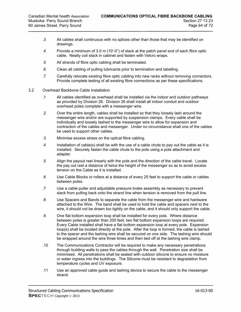
Canadian Mental health Association COMMUNICATIONS OPTICAL FIBRE BACKBONE CABLINGMuskoka- Parry Sound Branch Section 27 13 2360 James Street, Parry Sound Page 64 of 72
Structured Cabling Communications Specification 16-013-00Spectech Copyright 2013
.3 All cables shall continuous with no splices other than those that may be identified on drawings.
.4 Provide a minimum of 3.0 m (10’-0”) of slack at the patch panel end of each fibre optic cable. Neatly coil slack in cabinet and fasten with Velcro wraps.
.5 All strands of fibre optic cabling shall be terminated.
.6 Clean all cabling of pulling lubricants prior to termination and labelling.
.7 Carefully relocate existing fibre optic cabling into new racks without removing connectors. Provide complete testing of all existing fibre connections as per these specifications.
3.2 Overhead Backbone Cable Installation
.1 All cables identified as overhead shall be installed via the indoor and outdoor pathways as provided by Division 26. Division 26 shall install all indoor conduit and outdoor overhead poles complete with a messenger wire.
.2 Over the entire length, cables shall be installed so that they loosely lash around the messenger wire and/or are supported by suspension clamps. Every cable shall be individually and loosely lashed to the messenger wire to allow for expansion and contraction of the cables and messenger. Under no circumstance shall one of the cables be used to support other cables.
.3 Minimise excess stress on the optical fibre cabling.
.4 Installation of cable(s) shall be with the use of a cable chute to pay out the cable as it is installed. Securely fasten the cable chute to the pole using a pole attachment and adapter.
.5 Align the payout reel linearly with the pole and the direction of the cable travel. Locate the pay out reel a distance of twice the height of the messenger so as to avoid excess tension on the Cable as it is installed.
.6 Use Cable Blocks or rollers at a distance of every 25 feet to support the cable or cables between poles.
.7 Use a cable puller and adjustable pressure brake assembly as necessary to prevent slack from pulling back onto the strand line when tension is removed from the pull line.
.8 Use Spacers and Bands to separate the cable from the messenger wire and hardware attached to the Wire. The band shall be used to hold the cable and spacers next to the wire, it should not be drawn too tightly on the cable, and it should only support the cable.
.9 One flat bottom expansion loop shall be installed for every pole. Where distance between poles is greater than 200 feet, two flat bottom expansion loops are required. Every Cable installed shall have a flat bottom expansion loop at every pole. Expansion loop(s) shall be located directly at the pole. After the loop is formed, the cable is lashed to the spacer and the lashing wire shall be secured on one side. The lashing wire should be wrapped around the wire three times and then tied off at the lashing wire clamp.
.10 The Communications Contractor will be required to make any necessary penetrations through building walls to pass the cables through the wall. Penetration size shall be minimised. All penetrations shall be sealed with outdoor silicone to ensure no moisture or water ingress into the buildings. The Silicone must be resistant to degradation from temperature cycles and UV exposure.
.11 Use an approved cable guide and lashing device to secure the cable to the messenger strand.

Canadian Mental health Association COMMUNICATIONS OPTICAL FIBRE BACKBONE CABLINGMuskoka- Parry Sound Branch Section 27 13 2360 James Street, Parry Sound Page 65 of 72
Structured Cabling Communications Specification 16-013-00Spectech Copyright 2013
.12 Clamp cable to the exterior of the building with approved galvanised steel cable clamps.
3.3 Bend Radius
.1 Do not kink or exceed the cable minimum bend radius for all cabling. Maintain a minimum of ten (10) times the cable diameter or 30 mm (1.2”) whichever is larger for a bend radius.
3.4 Cable Lubricant
.1 Where there is the potential for excess stress on a cable(s) when pulling though conduit systems, apply a non-corrosive quick drying lubricant to the cable to facilitate pulling.
.2 Completely remove all cable lubricant from cable jacket as cable exits the conduit system prior to termination and labelling.
END OF SECTION

Canadian Mental health Association COMMUNICATIONS COPPER HORIZONTAL CABLINGMuskoka- Parry Sound Branch Section 27 15 1360 James Street, Parry Sound Page 66 of 72
Structured Cabling Communications Specification 16-013-00Spectech Copyright 2013
1 General
1.1 Work Included
.1 Comply with Section 27 00 03 – General Specifications and Requirements for Communications.
1.2 General
.1 Horizontal cabling shall be installed in pathways indicated on drawings and as per Section 27 05 28 of this specification.
.2 All cables shall be neatly bundled and installed as per the manufacturer’s guidelines or the standards in these specifications; whichever is more stringent.
.3 Ensure that all cables are sufficiently long to allow for slack, vertical runs, wastage, connectorization and future moves.
.4 The maximum horizontal run length shall not exceed 90-meters. If the 90 meter constraint cannot be met, the Communications Contractor shall notify the Technology Systems Consultant immediately (prior to installation).
2 Product
2.1 Horizontal Unshielded Twisted Pair (UTP) Copper Cabling
.1 All horizontal cabling shall be UTP, 4 pair, minimum 22 AWG, solid copper conductor, compliant with EIA/TIA cable category as identified below.
.2 The cable shall be CSA certified and stamped with CMP or CMR rating accordingly.
.3 All UTP cables shall meet requirements identified below.
Specified Product:Cat. Rating Colour System Termination
Belden 6 CMR/FT6 Blue Data/Voice Patch PanelHubbell 6 CMR/FT6 Blue Data/Voice Patch Panel
Notes: 1 Series or Product Codes shown are not colour specific.2 Cat.6+ is not a recognized category under TIA/EIA-568-B. It has been used in this instance to indicate that this cable when tested shows better margins compared to the same manufacturer’s standard Category 6 cable.
3 Execution
3.1 Horizontal UTP Cabling
.1 UTP cabling shall be terminated as per manufacturer’s guidelines and remove only enough cable jacket to perform termination.
.2 Untwist pairs a maximum of 13 mm (1/2”) for all categories of cables.

Canadian Mental health Association COMMUNICATIONS COPPER HORIZONTAL CABLINGMuskoka- Parry Sound Branch Section 27 15 1360 James Street, Parry Sound Page 67 of 72
Structured Cabling Communications Specification 16-013-00Spectech Copyright 2013
.3 Provide a minimum of 3.0 m (10’-0”) of slack at both ends of each cable. Neatly coil slack and attach to ladder tray or provide independent support in ceiling. Slack for workstation outlets shall be located above outlet in ceiling space.
.4 UTP cabling shall be neatly bundled using only Velcro wraps. Bundle cables separately for identification purposes when applicable.
.5 Comply with manufacturer’s recommended bundling practices for installation. Ensure that excess pressure is not placed on the cable at any point that may result in the compression or deformation of the cable jacket and internal pair/conductor geometry.
.6 Cables shall not be scrapped, dented or otherwise damaged before, during or after installation. All damaged cabling shall be replaced at no extra cost to the Owner.
.7 Ensure that all cables are of sufficient length to allow for slack, vertical runs, wastage, connectorization and future moves.
3.2 Cable Routing
.1 Make all necessary adjustments to cable route(s) / pathway(s) to accommodate architectural, structural, mechanical and/or electrical conditions.
.2 All pathways shall be parallel to building lines. If it is necessary to route cables otherwise to accommodate cable length written permission shall be obtained from the Technology Systems Consultant prior to installation.
.3 Any deviation from cable routing shown on drawings (where shown) shall be approved in writing by the Technology Systems Consultant prior to installation and shall be documented on record drawings.
3.3 Bend Radius
.1 Do not kink or exceed the cable minimum bend radius for all cabling. For all copper cabling maintain a minimum of (4) times cable diameter as bend radii if the manufacturer specifies no bend radius.
.2 Where there is the potential for excess stress on a cable(s) when pulling through conduit systems, apply a non-corrosive quick drying lubricant to the cable to facilitate pulling.
.3 Completely remove all cable lubricant from cable jacket as cable exits the conduit system prior to termination and labelling.
END OF SECTION

Canadian Mental health Association COMMUNICATIONS FACEPLATES AND CONNECTORSMuskoka- Parry Sound Branch Section 27 15 4360 James Street, Parry Sound Page 68 of 72
Structured Cabling Communications Specification 16-013-00Spectech Copyright 2013
1 General
1.1 Work Included
.1 Comply with Section 27 00 03 – General Specifications and Requirements for Communications.
1.2 Outlet Locations
.1 Horizontal cable outlets may be relocated prior to installation from the location shown on the drawings to a maximum distance of 3.05m (10’-0”) without adjustment to the contract price.
2 Product
2.1 UTP Termination Modules
.1 All UTP termination modules shall have the following minimum performance characteristics:
Modular jack current rating 1.5 Amperes maximumModular jack durability 1,000 mating cyclesModular jack contact pressure 100 grams minimum per contactDielectric voltage strength 1,000 V RMS at 60Hz for 1 minuteInsulation resistance 200 M minimumContact resistance 1 M per contactIDC termination connectors resistance 100 M between clips
.2 The contact material of the jack in a modular jack connector shall be phosphor bronze with 50 micro-inches of gold over nickel.
.3 UTP termination modules shall be of the same category as the UTP cabling to ensure that manufacturer end to end warranties can be attained.
.4 UTP cables shall be terminated with modules as listed below:
2.2 Optical Fibre Connectors
.1 Optical fibre terminations shall be made for field termination and shall be of the same manufacturer and style to suit the cabling installed.
.2 Fibre terminations shall be made with a ceramic ferrule and cable boot.
Specified Product:Cat.
Colour System
Belden 6 Blue Data/VoiceHubbell 6 Blue Data/Voice
Notes: 1 Cat.6A is not a recognized category under TIA/EIA-568-B. It has been used in this instance to indicate that this outlet is guaranteed by the manufacturer to meet Category 6A standards once the related standards are ratified.

Canadian Mental health Association COMMUNICATIONS FACEPLATES AND CONNECTORSMuskoka- Parry Sound Branch Section 27 15 4360 James Street, Parry Sound Page 69 of 72
Structured Cabling Communications Specification 16-013-00Spectech Copyright 2013
.3 Optical fibre cables shall be terminated with connectors as listed below:
Specified Product:Fibre Type
Belden MM LCHubbell MM LCCorning MM LC
2.3 Optical Fibre Adapter Strips
.1 Optical fibre adapter strips shall be of the same manufacturer and style to suit the cabling installed.
.2 Optical fibre patch panels shall be installed complete with optical fibre adapter strips as listed below:
Specified Product:Fibre Type
Belden MM LCHubbell MM LCCorning MM LC
2.4 Workstation Faceplates and Adapters
.1 Workstation outlets shall be supplied and installed for all terminations at the workstation end and as further specified below to suit the application.
.2 The Communications Contractor shall confirm colour of outlets prior to placing order.
.3 Workstation outlets shall be manufactured by the end to end solution manufacturer when available.
.4 Wall Faceplates
Specified Product:No. of Ports
Belden 2-portHubbell 2-port
2.5 Surface Mount Boxes
.1 Surface mount boxes shall be installed for all furniture outlets that do not have a modular furniture knockout, exposed ceiling outlets or any location not provided with an electrical backbox.
.2 The surface mounted box shall consist of a minimum of (2) ports.
.3 Each outlet shall be installed with the specified termination modules or a blank insert. No openings are to remain exposed.
.4 The Communications Contractor shall allow for the supply and installation of (10) blank plates and wall inserts to suit the application.
Specified Product:1No. of Ports
Belden 2-portHubbell 2-port

Canadian Mental health Association COMMUNICATIONS FACEPLATES AND CONNECTORSMuskoka- Parry Sound Branch Section 27 15 4360 James Street, Parry Sound Page 70 of 72
Structured Cabling Communications Specification 16-013-00Spectech Copyright 2013
.5 Blank inserts and faceplates shall be installed in all unused communication ports for workstation outlets. Blank insert plates shall be manufactured by the end to end solution manufacturer and be of the same colour as the workstation outlet.
3 Execution
3.1 Termination Requirements
.1 All cabling shall be terminated using EIA/TIA 568A configuration.
3.2 Workstation Outlets
.1 Install all workstation outlets level and flush to wall surface.
.2 Provide a final installation that is clean of all fingerprints and dirt complete with identification labelling as per these specifications.
END OF SECTION

Canadian Mental health Association COMMUNICATIONS PATCH CORDS AND CROSS-CONNECT WIREMuskoka- Parry Sound Branch Section 27 16 1960 James Street, Parry Sound Page 71 of 72
Structured Cabling Communications Specification 16-013-00Spectech Copyright 2013
1 General
1.1 Work Included
.1 Comply with Section 27 00 03 – General Specifications and Requirements for Communications.
1.2 General
.1 The Communications Contractor shall supply and install all cross-connects and patch cords at both ends unless otherwise noted.
.2 Cross-connects and patch cords shall be of the same manufacturer, quality and category to provide a complete end to end solution which shall be warranted by the selected manufacturer.
.3 Supply and install (2) patch cords for every horizontal cable installed.
.4 Provide miscellaneous cross-connects to owner supplied circuits as required.
1.3 Patch Cords
.1 All patch cords used shall be 8 position 4 pair T568A/B: T568A/B patch cords unless otherwise noted.
.2 All patch cords shall be CMR (FT4) rated and stamped accordingly and shall be consistent with the category and manufacturer of the UTP cabling system that shall be warranted as part of the end to end solution.
2 Product
2.1 UTP Patch Cords
.1 All patch cords shall be CMR (FT4) rated and stamped accordingly.
.2 Patch cords shall be manufactured of stranded conductor cable with (8) position (4) pair terminations at both ends.
Specified Product:Cat. Rating Colour Length System Location
Belden 6 CMR/FT4 Blue 7’ Data Telecom RoomHubbell 6 CMR/FT4 Blue 7’ Data Telecom RoomBelden 6 CMR/FT4 Blue 10’ Data WorkstationHubbell 6 CMR/FT4 Blue 10’ Data Workstation
Notes: 1 Cat.6+ is not a recognized category under TIA/EIA-568-B. It has been used in this instance to indicate that this cable when tested shows better margins compared to the same manufacturer’s standard Category 6 cable.2 Cat.6A is not a recognized category under TIA/EIA-568-B. It has been used in this instance to indicate that this cable is guaranteed by the manufacturer to meet Category 6A standards once the related standards are ratified.

Canadian Mental health Association COMMUNICATIONS PATCH CORDS AND CROSS-CONNECT WIREMuskoka- Parry Sound Branch Section 27 16 1960 James Street, Parry Sound Page 72 of 72
Structured Cabling Communications Specification 16-013-00Spectech Copyright 2013
2.2 Optical Fibre Patch Cords
.1 All patch cords shall be CMR (FT4) rated and stamped accordingly.
Specified Product:Rating Length
Belden CMR/FT4 MM 10’Corning CMR/FT4 MM 10’Hubbell CMR/FT4 MM 10’
Notes: 1 Cat.6+ is not a recognized category under TIA/EIA-568-B. It has been used in this instance to indicate that this cable when tested shows better margins compared to the same manufacturer’s standard Category 6 cable.2 Cat.6A is not a recognized category under TIA/EIA-568-B. It has been used in this instance to indicate that this cable is guaranteed by the manufacturer to meet Category 6A standards once the related standards are ratified.
3 Execution
3.1 UTP Patch Cords
.1 Assume all ports shall be patched.
3.2 Optical Fibre Patch Cords
.1 Assume all ports shall be patched.
3.3 Cross-Connects
.1 Assume all pairs of all cables are cross-connected at both ends.
.2 Install cross-connects and patch cords for each termination using cable management in a neat and workmanship fashion acceptable to the owner and the Technology Systems Consultant.
.3 Provide cross-connects for all connections required by the Owner to complete the installation.
.4 Use velcro wraps to provide additional cable management as required.
.5 Provide additional “D” rings and cable management for cross-connects as required.
END OF SECTION

Canadian Mental Health Association STRUCTURED CABLING COMMUNICATIONS TENDER FORMMuskoka- Parry Sound Branch Section 27 00 00.0060 James Street, Parry Sound, Ontario Page 1 of 4
Structured Cabling Communications Tender Form 16-013-00Spectech Copyright 2013
Structured Cabling Communications Tender Form v.5.2 – 2013-01-21
Project: CMHA Muskoka Parry Sound Project No: 16-013-00
Submitting Contractor: Date:
1 Instructions to Bidders
1.1 Complete all sections of the tender form. Tender forms not fully complete may be considered non-compliant and eliminated from further evaluation.
1.2 An electronic version of this form is available upon request in a password protected “Form” format (i.e. fill in the blank) for Microsoft Word. Make your request via email to the Technology Systems Consultant identified in the Specification. The electronic version of this form shall not be used to submit tender response electronically, but rather to assist the contractor in preparing the bid. Microsoft Word 2003 or better shall be required.
1.3 This tender form shall form part of a contract if awarded, and the successful bidder may be required to complete a CCDC-2 contract.
1.4 Bidding Contractor shall not add to, delete from or modify this tender form.
1.5 For definitions and abbreviations refer to Section 27 00 05 – Definitions and Abbreviations for Communications.
2 Acknowledgement
2.1 We have read and understand the content of the Structured Cabling Communications Specifications, Drawings and Amendments (Addenda) issued for tender and agree to all terms and conditions. Our stipulated sum including all labour, materials, and equipment necessary to complete the work set out in the tender documents listed shall be:
$(Net-Total) (CAD)
$(Applicable Sales Taxes at: % ) (CAD)
$(Total with Applicable Sales Taxes) (CAD)
2.2 Our Net-Total includes all allowances and costs, except for Applicable Sales Taxes, which shall be shown separately on all documents and invoices.
3 Tender Documents

Canadian Mental Health Association STRUCTURED CABLING COMMUNICATIONS TENDER FORMMuskoka- Parry Sound Branch Section 27 00 00.0060 James Street, Parry Sound, Ontario Page 2 of 4
Structured Cabling Communications Tender Form 16-013-00Spectech Copyright 2013
3.1 The following are the Structured Cabling Communications Tender Documents considered part of this tender and the bidder acknowledges receiving these documents for the preparation of this tender submission:
Structured Cabling Communications Tender Form 4 pages
Structured Cabling Communications Specifications 72 pages
Structured Cabling Communications Drawings 6 drawings (as listed in Specification)
Addendum # - page(s)Structured Cabling Communications Addenda
Addendum # - page(s)
Addendum # - page(s)
4 Substantial Completion
4.1 We agree to substantially complete our work in weeks.
5 Unit Pricing
5.1 The following unit prices shall be used throughout the duration of this project. All pricing to supply and install shall include all charges and costs associated with performing the work. No additional allowances for items such as profit, overhead, supervision, transportation, delivery or any cost shall be accepted. All unit prices shall be based on performing the work as per the specifications. NB. - * “Delete Amount” shall not be less than 80% of the “Add Amount”.
Description Add* Delete*
Communications Rack c/w all accessories and grounding $ $
UTP Horizontal Cable Drop c/w up to 150’ of UTP cable, workstation outlet, termination modules, labeling and testing and update documentation (cable slack and wastage shall be included in price, but shall be above and beyond the length noted above) $ $
Same as Above c/w (2) cables to a single location $ $
Same as Above c/w (3) cables to a single location $ $
7’ Copper Patch Cords $ $
10’ Copper Patch Cords $ $
6 Hourly Rates

Canadian Mental Health Association STRUCTURED CABLING COMMUNICATIONS TENDER FORMMuskoka- Parry Sound Branch Section 27 00 00.0060 James Street, Parry Sound, Ontario Page 3 of 4
Structured Cabling Communications Tender Form 16-013-00Spectech Copyright 2013
6.1 The following hourly rates shall be used for the evaluation of changes in scope and shall be effective throughout the duration of the project.
Regular Hours (7:00 am – 5:00 pm) $ / hour
Evening Hours (5:01pm – 6:59 am) $ / hour
Premium Hours (Weekends / Holidays) $ / hour
7 Evaluation Information
7.1 We have selected to complete this project with an end to end solution from:
7.2 Provide and attach a detailed material list proposed for use on this project. Include the following:
7.2.1 Item Description
7.2.2 Product Description
7.2.3 Product Code or Part Number
7.2.4 Quantity
7.3 We have provided our bid with the request for approval of the following Sub-Contractor (if no Sub-Contractor shall be used, please enter “We shall use our own forces”):
(We understand that approval of this Sub-Contractor may not be granted and an acceptable, agreed upon alternate Sub-Contractor may be required before acceptance of this bid.)
7.4 Our Project Manager for this project shall be
7.5 Our Foreman or Lead Technician shall be:
8 Submission
8.1 This tender submission is submitted by:
(Company)
(Address)
Authorized Signing Officer:
(Print)

Canadian Mental Health Association STRUCTURED CABLING COMMUNICATIONS TENDER FORMMuskoka- Parry Sound Branch Section 27 00 00.0060 James Street, Parry Sound, Ontario Page 4 of 4
Structured Cabling Communications Tender Form 16-013-00Spectech Copyright 2013
(Signature)
(Date)
(Date)
End of Section 27 00 00.10 – Structured Cabling Communications Tender Form

Prepared by
SpecTECHTechnology Consulting and Project Managementa division of Spectech Holdings Inc.
201-17360 Yonge StreetNewmarket, OntarioL3Y 7R6
Web: www.spectech.caEmail: [email protected]: 416-360-8800Facsimile: 905-898-1988
Technology Partner For
Building Information Modelling Data Centre/Server Rooms Cabling Infrastructure Wireless LAN IP Telephony Network Hardware Audio Video CATV IP Based Security Connectivity Services Specialty Power Systems
Services
Feasibility Studies Technology Audits Project Management Design and Documentation Design Build Solutions Technical Training MAC Management
Proven
Professional
Trustedv.6 – 2016-06-13
Electronic Safety and Security SpecificationAccess ControlIntrusion DetectionVideo SurveillanceElectronic Personal Protection
For
CMHA Muskoka Parry Sound
60 James StreetParry Sound, Ontario
1st and 2nd Floor
Our Project Number 16-013-02

Canadian Mental Health Association TABLE OF CONTENTS AND DRAWING LISTMuskoka- Parry Sound Branch Section 28 00 0060 James Street, Parry Sound, Ontario Page 2 of 87
Electronic Safety and Security Specification 16-013-02Spectech Copyright 2016
Table of Contents
28 00 03 General Specifications and Requirements for Electronic Safety and Security..................328 00 05 Definitions and Abbreviations for Electronic Safety and Security ..................................1228 00 07 Codes and Standards for Electronic Safety and Security .............................................1928 00 09 Scope of Work for Electronic Safety and Security .......................................................2328 00 11 Administrative Requirements for Electronic Safety and Security...................................2528 00 13 Fire Stopping for Electronic Safety and Security .........................................................2828 00 15 Electronic Safety and Security Cable and Equipment Removal Requirements ..............3228 05 13.13 CCTV Communications Conductors and Cables.........................................................3428 05 13.16 Access Control Communications Conductors and Cables ...........................................3528 05 13.19 Intrusion Detection Communications Conductors and Cables ......................................3728 05 26 Grounding and Bonding for Electronic Safety and Security ..........................................3828 05 28 Pathways for Electronic Safety and Security ..............................................................4128 05 53 Identification for Electronic Safety and Security ..........................................................4328 08 00 Commissioning of Electronic Safety and Security .......................................................4528 13 00 Access Control Systems...........................................................................................4828 16 00 Intrusion Detection Systems .....................................................................................6928 23 00 Video Surveillance Systems......................................................................................7528 26 13 Electronic Personal Protection Systems.....................................................................83
Tender Form
28 00 00 Electronic Safety and Security Tender Form……………………………………..…..ESSTF.1
Drawing List (drawings provided under separate cover)
ES-001 Electronic Safety and Security Schematics & LegendES-101 Level 01 Electronic Safety and Security Floor PlanES-102 Level 02 Electronic Safety and Security Floor PlanES-301 Electronic Safety and Security Riser DiagramES-501 ESS Door DetailsES-502 ESS Door Details

Canadian Mental Health Association GENERAL SPECIFICATIONS AND REQUIREMENTS FOR ESSMuskoka- Parry Sound Branch Section 28 00 0360 James Street, Parry Sound, Ontario Page 3 of 87
Electronic Safety and Security Specification 16-013-02Spectech Copyright 2016
1 General
1.1 Work Included
.1 Conform to the requirements of Divisions 0 and 1 and additional general information as prepared by the Architect or Prime Consultant, which apply to and form part of all sections of the work.
.2 Read and comply with all sections of this document.
.3 These instructions apply to and form part of all Electronic Safety and Security Sections and drawing(s).
.4 Refer to section 28 00 05 for definitions of names, titles, terms and abbreviations used in this document.
.5 These documents have been prepared by Spectech specifically for use on this project and may not be reproduced in whole or in part without the express written consent of Spectech. These documents may not be used for any other purpose and/or for any other project and are considered confidential for the use of preparing a tender response.
.6 This specification is divided into Sections which are not intended to identify contractual limits between Sub-Contractors nor between the Contractor and his Sub-Contractors. The requirements of any one Section apply to all Sections. Refer to other Divisions and Sections to ensure a complete and operational system.
.7 These tender documents shall remain the property of the Technology Systems Consultant at all times.
.8 The Electronic Safety and Security Contractor shall report any discrepancies between drawings and all applicable specifications to the Technology Systems Consultant immediately.
.9 All drawings and details have been prepared to illustrate the existing and new conditions of the project and shall be considered diagrammatic. The Electronic Safety and Security Contractor shall ensure all components required to complete the fully operational system are installed with no additional cost to the Owner or the Technology Systems Consultant.
.10 Provide all labour, materials, tools and equipment required for the complete installation of work called for in all Sections of the Contract Documents.
.11 The Electronic Safety and Security Contractor shall verify exact locations of all items shown and shall verify with the Technology Systems Consultant all new locations prior to installation. It shall be the responsibility of the Electronic Safety and Security Contractor to provide the Technology Systems Consultant detailed layouts of all rooms and locations of installation prior to installation for approval. All costs, including other trades as applicable, associated with changes resulting from non-approved installation will be the responsibility of the Electronic Safety and Security Contractor.
.12 Minor changes in locations may be required by the Technology Systems Consultant in order to coordinate site conditions with other divisions and the Technology Systems Consultant reserves the right to make these changes with no additional cost to the Owner.
1.2 Schedule
.1 The Electronic Safety and Security Contractor shall be responsible to meet the project schedule as provided by the Project Manager and the Owner.

Canadian Mental Health Association GENERAL SPECIFICATIONS AND REQUIREMENTS FOR ESSMuskoka- Parry Sound Branch Section 28 00 0360 James Street, Parry Sound, Ontario Page 4 of 87
Electronic Safety and Security Specification 16-013-02Spectech Copyright 2016
.2 Work is generally to be performed during regular work hours unless noted otherwise in this document. The Electronic Safety and Security Contractor shall include for all necessary overtime labour in order to complete the project. The Electronic Safety and Security Contractor shall be responsible for providing labour in order to complete the work within the schedule with no additional cost to the Owner.
.3 The Electronic Safety and Security Contractor shall supply a written project plan detailing schedule of installation in coordination with the overall project schedule. Project plan shall be prepared in MS Project.
.4 At and near the completion of the project the Electronic Safety and Security Contractor will be responsible for providing project documentation for the Owner’s further use. This will include:
.1 Updated Excel Spreadsheet documenting the following:
.1 Cat6 cable numbers (e.g. L1-01-001)
.2 Description & name device connected to Cat6 cable
.3 IT Room Number cable is terminated in (e.g. L1-01)
.4 Switch name/identification device is connected (e.g. L1-01-2960X-1)
.5 Switch port device is connected to (e.g. port 14)
.2 Temporary As-Builts
.3 Contact Info for Cutover Technician
.4 Cable Test Results
.5 All documents and information shall be provided as further detailed in Section 28 00 09 and delivered to the Technology Systems Consultant.
1.3 Labour
.1 The Electronic Safety and Security Contractor shall provide only skilled, trained tradesmen experienced in the installation of a certified installation. Each installer shall be certified with the manufacturer providing the warranty for this project.
.2 The Electronic Safety and Security Contractor shall be responsible to provide Union or Non-union labour as required on the project site and meet all requirements without any delay or cost to the Owner, General Contractor or other trades.
.3 Sub-Contractors shall not be allowed to perform all or any portion of the project unless approved in writing by the Technology Systems Consultant and the Owner. Subcontractors shall be identified at time of tender to be considered for approval.
.4 The Electronic Safety and Security Contractor shall be in compliance at all times with local, provincial and federal employee standards, safety acts, fire codes and other applicable legislations, codes and acts affecting the delivery of the project. The Electronic Safety and Security Contractor is responsible for the training and notifying their employees of any details associated with all codes, standards, acts and legislation applicable to this project.
.5 WSIB (Workplace Safety Insurance Board) clearance certificate indicating a good standing shall be provided by the Electronic Safety and Security Contractor prior to acceptance of any contract.
.6 Provide personal identification in a form acceptable to the Owner for all employees attending the site for this project when requested.
1.4 Interpretation of Drawings and Specifications

Canadian Mental Health Association GENERAL SPECIFICATIONS AND REQUIREMENTS FOR ESSMuskoka- Parry Sound Branch Section 28 00 0360 James Street, Parry Sound, Ontario Page 5 of 87
Electronic Safety and Security Specification 16-013-02Spectech Copyright 2016
.1 It is the responsibility of the Electronic Safety and Security Contractor to read carefully these specifications and drawing(s) and report any discrepancies immediately to the Technology Systems Consultant.
.2 While every attempt has been made to ensure that all information (including specified products and part numbers) is correct, it is the responsibility of the Electronic Safety and Security Contractor to verify availability of products and verify all part numbers.
.3 Specifications and drawings are schematic and represent the intent of the project.
.4 Dimensions and measurements shown in these documents shall be verified by the Electronic Safety and Security Contractor on site prior to final installation.
.5 Quantities and lengths identified are approximate and shall not be used to gauge or limit work.
.6 These Specifications are an integral part of the accompanying drawing(s). Any item or subject omitted from one or the other, but which is either mentioned or implied shall be considered as properly and sufficiently specified.
.7 Certain details indicated on the drawings are general in nature and are not specifically identified for each and every occurrence of use, however, such details shall be applicable to every occurrence on the drawings.
.8 The location and size of existing services and equipment shown on the drawings are based on the best available information. The Electronic Safety and Security Contractor shall verify the exact location, type, size and any other pertinent information prior to commencing work.
1.5 Installation
.1 Leave areas clear where space has been designated as reserved for future equipment and equipment for other trades.
.2 Adequate space and provisions shall be left for removal of components and servicing of equipment, with minimum inconvenience to the operation of systems.
.3 Where equipment is shown to be ‘roughed in only’ obtain information from the Technology Systems Consultant before proceeding with the work.
1.6 Coordination
.1 The Electronic Safety and Security Contractor shall provide an installation and make all changes associated with coordination with other trades and to accommodate unforeseen site conditions at no additional cost to the Owner.
.2 Prepare interference drawings and sketches for presentation to the Technology Systems Consultant to review any anticipated conflicts with other trades.
.3 Prepare detailed layouts of equipment rooms prior to installation for review by the Technology Systems Consultant. Layouts shall indicate other major pieces of equipment being supplied by other trades.
.4 The Electronic Safety and Security Contractor shall be responsible for attending coordination meetings as requested by the General Contractor or Project Manager for the coordination of locations and services. The Contractor’s project co-ordinator selected shall be assigned for the duration of the project and may only be changed with the written consent of the Technology Systems Consultant.
.5 The Electronic Safety and Security Contractor in addition to coordination meetings shall attend weekly site meetings and be prepared to provide current project progress status, anticipated completion of future tasks and information on outstanding delivery items.

Canadian Mental Health Association GENERAL SPECIFICATIONS AND REQUIREMENTS FOR ESSMuskoka- Parry Sound Branch Section 28 00 0360 James Street, Parry Sound, Ontario Page 6 of 87
Electronic Safety and Security Specification 16-013-02Spectech Copyright 2016
.6 Access to the site shall be in compliance to all rules, regulations, safety standards and security procedures established for the project or building. Fees for after hours access shall be considered included in the tender amount. No additional cost shall be accepted by the Owner for these requirements.
.7 Cutting and patching of all surfaces as applicable to the electronic safety and security installation shall be the responsibility of and be performed by the Electronic Safety and Security Contractor. All work shall be performed to the standards set by codes and standards, Building Management, General Contractor and the Owner.
.8 Cutting and patching of all structural members shall be approved by the Structural Consultant prior to work starting.
.9 Work causing noise, dust and/or odour shall be performed during evenings and/or weekends to prevent disturbance to the operation of the Owner’s or surrounding businesses. Work shall be performed at agreed times and in coordination with each party. All damages caused for work performed not in compliance with this item shall be the responsibility of the Electronic Safety and Security Contractor.
1.7 Temporary Services
.1 The Electronic Safety and Security Contractor shall provide all required materials, labour, tools and equipment to meet the temporary requirements of the project in coordination with other trades and the General Electronic Safety and Security Contractor at no additional cost to the Owner.
.2 All hoisting, mechanical lifts and special scaffolds shall be the responsibility of the Electronic Safety and Security Contractor and at no additional cost to the Owner.
.3 All power supplies, extension cords and equipment cords shall be the responsibility of the Electronic Safety and Security Contractor and shall be installed in good working order and in accordance with all codes, standards and building regulations.
1.8 Co-Operation With Other Divisions
.1 Electronic Safety and Security Cabling shall not touch or be supported from piping, ductwork, conduits, ceiling supports or any other service / equipment. Electronic Safety and Security Cabling shall be supported by approved j-hooks, cable slings, ladder / basket tray and/or conduit as outlined in this document.
.2 Supply all items to be built in ample time for rapid progression of the work. Schedule and provide manpower and materials to proceed with work as required to satisfy the construction schedule.
1.9 Existing Services and Equipment
.1 All changes and connections to existing services shall be made only in a manner and at a time approved by the Technology Systems Consultant and/or the Owner so as to avoid any interruption of such services during normal working hours. If necessary, changes and connections to existing services shall be made outside of normal business hours at no extra cost to the Owner.
1.10 Metric Conversions
.1 Particular attention shall be paid with regard to Imperial versus S.I. Metric conversions. This applies to all services including, but not limited to, equipment, material and site services in both new and existing installations.
.2 Conform to Canadian Metric Practice Guide CSA-CAN3-2234-1-89.

Canadian Mental Health Association GENERAL SPECIFICATIONS AND REQUIREMENTS FOR ESSMuskoka- Parry Sound Branch Section 28 00 0360 James Street, Parry Sound, Ontario Page 7 of 87
Electronic Safety and Security Specification 16-013-02Spectech Copyright 2016
1.11 Monthly Draws
.1 Monthly progress draws shall be submitted to the General Contractor for approval by the Technology Systems Consultant.
1.12 Pricing of Changes
.1 Where a Contemplated Change Notice (CCN) has been issued and identifies potential changes to the scope of work and those changes have been price-identified in the Tender Form under the Alternate, Separate, Identified and/or Unit Pricing structure, the Electronic Safety and Security Contractor shall price all changes in accordance with the pricing provided in the Tender Form at the time of tender. All prices shall be provided in a broken down format, identifying the pricing reference (i.e. The line item on the Tender Form).
.2 Where a CCN has been issued and identifies potential changes to the scope of work and those changes have NOT been price-identified in the Tender Form under the Alternate, Separate, Identified and/or Unit Pricing structure, the Electronic Safety and Security Contractor shall provide a complete breakdown of all material, equipment and labour cost associated with each submission in the following format.
All material used in the change(s) shall be identified by:
QuantityPrice Per UnitMaterial CostHours per UnitTotal Hours
Summary shall include:
Total Material ValueHSTTechnician rate (as per Tender Form)Forman rateOverheadMarkup (profit)
Contemplated Change Notices shall include at no extra cost:
AdministrationRecord DrawingsClean upCo-ordinationEngineering and DraftingEstimatingGuaranteeHydro InspectionMaterial DeliveryMaterial ExpeditingMileageParkingProject ManagementRe-Assign ManpowerSafetySchedule ExtensionSupervision

Canadian Mental Health Association GENERAL SPECIFICATIONS AND REQUIREMENTS FOR ESSMuskoka- Parry Sound Branch Section 28 00 0360 James Street, Parry Sound, Ontario Page 8 of 87
Electronic Safety and Security Specification 16-013-02Spectech Copyright 2016
Tool ChargesWastageWarranty
Foreman Charges: Foreman Charges shall not exceed 10% of the labour component of the price.
Overhead and Profit: All overhead fees and profit shall be fixed at 5% and 10% unless agreed to by the owner / consultant prior to installation.
2 Product
2.1 General
.1 All equipment and products supplied shall be new and free of all manufacturer defects and delivery or installation damage.
.2 All equipment and products supplied shall meet all manufacturer listed characteristics as identified in the latest manufacturer catalogue.
.3 All products shall meet all applicable codes and standards and bare the UL/ULC label, be CSA approved and meet FCC/CRTC Regulations.
.4 All products shall be provided in accordance with local, provincial and national fire ratings for the installation on this project.
.5 The only acceptable Manufacturers for this project and as further specified in this document will be the following:
S2 Access ControlHartman Access ControlDSC Intrusion DetectionIndigovision Video SurveillanceHikvision Video Surveillance
2.2 Certification
.1 Certification shall be provided by the specified and selected product manufacturer directly to the Technology Systems Consultant.
.2 The Electronic Safety and Security Contractor is responsible for providing to the Technology Systems Consultant a copy of the applications for certification with 5 days of project award.
.3 Upon completion of the project the Electronic Safety and Security Contractor shall deliver to the Technology Systems Consultant a copy of the manufacturer’s warranty information, certificate and or plaque. This information shall accompany the final documentation described further in these specifications.
.4 The Electronic Safety and Security Contractor shall currently be an authorized installer of the manufacturer providing the warranty.
.5 Subcontractors shall not be acceptable to provide warranty unless pre-approved by the Technology Systems Consultant at time of tender. Subcontractors will not be approved after tender is awarded.

Canadian Mental Health Association GENERAL SPECIFICATIONS AND REQUIREMENTS FOR ESSMuskoka- Parry Sound Branch Section 28 00 0360 James Street, Parry Sound, Ontario Page 9 of 87
Electronic Safety and Security Specification 16-013-02Spectech Copyright 2016
.6 The Electronic Safety and Security Contractor shall provide a written 2 years (minimum) warranty inclusive of all parts and labour for each system. The Electronic Safety and Security Contractor shall also state and agree in writing to providing response for any warranty request within 24 hours during this warranty period.
2.3 Substitutions
.1 Substitution of any product shall be prior approved in writing by only the Technology Systems Consultant.
.2 The procedure for substitution approval will include the written submission by the Electronic Safety and Security Contractor including the following:
.1 Original specified product
.2 Proposed product being substituted
.3 Reason for substitution
.4 Shop drawings indicating all technical specifications
.5 Financial advantage
.6 Schedule delivery date
.7 Written approval from certifying system manufacturer
.3 Based on the review of the information requested above, the Owner and/or Technology Systems Consultant reserve the right to reject any proposed substitution without delay or cost to the project or the Owner.
2.4 Material Handling
.1 The Electronic Safety and Security Contractor is responsible for the delivery of all materials to site and transportation to the work place in accordance with all safety regulations and procedures.
.2 Make arrangements and schedule all hoisting with Building Management and the General Contractor.
.3 Provide and be responsible for lockable storage for all tools and material required to complete the installation through the duration of the project. Once the project is complete remove all tools and excess materials within 2 business days.
.4 The Owner and its representatives shall in no way be held liable for any missing material, equipment or tools required to complete the installation.
3 Execution
3.1 General
.1 The Electronic Safety and Security Contractor shall supply all materials, labour, tools and equipment to provide a complete warranted installation as outlined in the contract documents and suitable to the approval of the Owner, Technology Systems Consultant and inspection bodies having jurisdiction.
.2 The Electronic Safety and Security Contractor shall be responsible for installing and providing pulling strings, ropes and fishing walls wherever conduit is not installed or conduit is installed without these provisions.

Canadian Mental Health Association GENERAL SPECIFICATIONS AND REQUIREMENTS FOR ESSMuskoka- Parry Sound Branch Section 28 00 0360 James Street, Parry Sound, Ontario Page 10 of 87
Electronic Safety and Security Specification 16-013-02Spectech Copyright 2016
.3 Provide continuity of all existing services while completing the specified installation. Losses due to interruption of services will be the responsibility of the Electronic Safety and Security Contractor.
.4 Arrange for all shutdowns one (1) week prior in writing with the Project Manager and those in control of services shall be disrupted. All overtime costs, fees, security and other requirements shall be the full responsibility of the Electronic Safety and Security Contractor.
.5 Should services be interrupted accidentally the Electronic Safety and Security Contractor shall provide material and labour to re-establish services immediately and shall continue without stoppage until all services have been re-established. All material and labour costs including overtime shall be borne solely by the Electronic Safety and Security Contractor. Any material and/or labour costs including overtime associated with other trades and/or the General Contractor to assist in any way the Electronic Safety and Security Contractor in re-establishing services shall be borne solely by the Electronic Safety and Security Contractor.
3.2 Site Conditions
.1 The Electronic Safety and Security Contractor is responsible for maintaining a clean work environment and is responsible for the removal of all debris on a daily basis. Debris and removed materials shall be disposed of in conformance with all local by laws and regulations. Failing to comply and after reasonable time and written notice the General Contractor reserves the right to hire cleaners to complete the cleaning and back charge the Electronic Safety and Security Contractor.
.2 The Electronic Safety and Security Contractor shall be responsible for the removal and reinstallation of all floor or ceiling tiles, hatch ways or access panels. All items shall be removed and replaced on a daily basis and left in the original condition. Special caution shall be taken to not break, chip or discolour with dirt or finger prints any such items. The Electronic Safety and Security Contractor will be fully responsible for repair or replacement of all damaged pieces at the discretion of the Project Manager or Owner.
.3 The Electronic Safety and Security Contractor is fully responsible for storage of all temporarily removed items for the project.
.4 All materials and installation throughout the project will remain the responsibility of the Electronic Safety and Security Contractor until final completion for the project is accepted by the Owner. Damages to any item installed shall be replaced or repaired by the Electronic Safety and Security Contractor to provide a complete final installation at no additional cost to the Owner.
.5 At the completion of the project or as and when the Owner requires, restore the original condition of all materials, equipment and surfaces within the wok area affected by this installation.
.6 All vehicular traffic entering the site shall be coordinated with the General Contractor and no parking or compensation for paid parking will be provided by the Owner.
3.3 Cutting, Patching and Repairing
.1 It is the responsibility of the Electronic Safety and Security Contractor to perform all cutting, patching and repair related to the Electronic Safety and Security Cabling work including any penetrations through walls or floors.
3.4 Hoisting Facilities

Canadian Mental Health Association GENERAL SPECIFICATIONS AND REQUIREMENTS FOR ESSMuskoka- Parry Sound Branch Section 28 00 0360 James Street, Parry Sound, Ontario Page 11 of 87
Electronic Safety and Security Specification 16-013-02Spectech Copyright 2016
.1 This Division shall provide its own hoisting facilities regardless of height required to perform work.
.2 Hoisting facilities may be provided by the General Contractor, although the General Contractor may at its own discretion not allow the Electronic Safety and Security Contractor to make use of such.
3.5 Safety
.1 The Electronic Safety and Security Contractor shall adhere to all safety laws, rules and regulations issued by the authorities having jurisdiction, General Contractor, Project Manager and the Owner.
.2 The Electronic Safety and Security Contractor shall attend all Safety Program meetings requested by the General Contractor.
.3 Provide adequate protection in public and work areas to pedestrian and other trade traffic using approved safety barriers, caution tape and signage.
.4 At all times maintain clear fire exits, emergency routes and access to emergency equipment including fire hose cabinets, fire extinguishers and stand pipe connections.
.5 Smoking and combustion of any materials is strictly prohibited on all sites.
.6 Provide information to all employees of emergency and fire safety plans for the work site and facility.
.7 Provide protection as required by the authorities having jurisdiction to all employees for work performed in typically inaccessible or concealed spaces.
.8 If an approved subcontractor is used provide information and ensure all safety specifications herein are meet.
3.6 Site Adjustments
.1 Locations or all equipment, outlets or devices prior to installation may be revised to within (3) meters without any additional cost or change request.
.2 Portions of the project may be at any time identified in writing to be “On Hold”. Work in these areas shall not be started, continued or completed until further direction is received. No additional cost shall be accepted by the Owner for areas put on hold.
END OF SECTION

Canadian Mental Health Association DEFINITIONS AND ABBREVIATIONS FOR ESSMuskoka- Parry Sound Branch Section 28 00 0560 James Street, Parry Sound, Ontario Page 12 of 87
Electronic Safety and Security Specification 16-013-02Spectech Copyright 2016
1 General
1.1 General
.1 The following definitions may be used in this document, as well as in any project documents such as but not limited to Addenda, Contemplated Change Notices, Change Orders, and Site Instructions:
Addendum - Normative document used to provide additional requirements and recommendations to a published document (e.g., standards, contracts). When published, an addendum effectively becomes part of the document that it supports.
Bonding - The permanent joining of metallic parts to form an electrically conductive path that will ensure electrical continuity and the capacity to conduct safely any current likely to be imposed.
Bonding Conductor (BC) - A conductor used specifically for the purpose of bonding.
Building Entrance Facility - The room or space inside a building where telecommunications cables enter and leave the building.
Electronic Safety and Security Contractor
- The successful bidder(s) responsible for the supply and installation of the Electronic Safety and Security solution as described in this Specification.
Category - A rating that defines the performance of cabling components and systems. Describes mechanical properties and transmission characteristics of balanced twisted-pair cabling and provides a numbered designation.
Change Notice - Normative document approved to provide additional requirements and recommendations that describes and authorizes the implementation of an engineering change to the product and its approved configuration documentation.
Owner - CMHA Muskoka Parry Sound
Technology Systems Consultant
- Derek RichardsonSpectech Technology Consulting and Project Managementa division of Spectech Holdings Inc.411 Queen StreetNewmarket, Ontario L3Y 2G9
Contemplated Change Notice
- Normative document to provide additional requirements and recommendations that describes

Canadian Mental Health Association DEFINITIONS AND ABBREVIATIONS FOR ESSMuskoka- Parry Sound Branch Section 28 00 0560 James Street, Parry Sound, Ontario Page 13 of 87
Electronic Safety and Security Specification 16-013-02Spectech Copyright 2016
the implementation of an engineering change to the product and its approved configuration documentation for the purposes of pricing. This document does not authorize the implementation of a change to the product and its approved configuration documentation.
Cut Over - The live date(s) when the Owner will occupy the space as indicated by date and/or phasing.
Grounded Conductor - A system or circuit conductor that is intentionally grounded.
Grounding System - A system of hardware and wiring that provides an electrical path from a specified location to an earth ground point.
Project - Supply and installation of a complete Electronic Safety and Security solution to support Access Control, Intrusion Detection, Video Surveillance and Electronic Personal Protection system as described in this document.
Provide - Supply and install.
Shop Drawing - Drawings, diagrams, illustrations, schedules, performance charts, and other data prepared by the contractor which illustrate how specific portions of the work shall be installed. This includes but not limited to point to point high level integration diagram, riser diagram, termination diagram, panel layout, door types and product data sheet.
.2 The following abbreviations may be used in this document:
A - AmpereA/E - Architect or Engineerac - Alternating currentACR - Attenuation to Cross-Talk RatioADC - Analog to Digital ConverterADSL - Asymmetric Digital Subscriber LineAFF - Above Finished FloorAHJ - Authority Having JurisdictionALPETH - Aluminum PolyethyleneAME - Architectural, Mechanical, ElectricalAN - Access NodeANSI - American National Standards InstituteAP - Access PointARPAP - Resin-coated Aluminum, Polyethylene Aluminum, PolyethyleneASCII - American Standard Code for Information InterchangeASP - Aluminum Steel PolyethyleneASTM - American Society for Testing and MaterialsATD - Asynchronous Time DivisionATDM - Asynchronous Time Division Multiplexing

Canadian Mental Health Association DEFINITIONS AND ABBREVIATIONS FOR ESSMuskoka- Parry Sound Branch Section 28 00 0560 James Street, Parry Sound, Ontario Page 14 of 87
Electronic Safety and Security Specification 16-013-02Spectech Copyright 2016
ATM - Asynchronous Transfer ModeAttn - AttenuationAV - AudiovisualAWG - American Wire Gaugeb/s - Bit per SecondBAS - Building Automation SystemBC - Bonding ConductorBCD - Backbone ConduitBCT - Bonding Conductor for TelecommunicationsBEF - Building Entrance FacilityBER - Bit Error RateBERT - Bit Error Rate TestBFOC - Bayonet Fibre Optic ConnectorBIC - Building Industry ConsultantBICSI® - Building Industry Consulting Service Internationalbit - Binary DigitBOM - Bill Of MaterialBWA - Broadband Wireless Accessc/w - Complete WithCA - CableCACSP - Coated Aluminum Coated Steel PolyethyleneCAD - Computer Aided DesignCATV - Community Antenna Television (Cable Television)CBN - Common Bonding NetworkCCIA - Computer Communications Industry AssociationCCN - Contemplated Change NoticeCCTV - Closed Circuit TelevisionCD - Compact DiscCD - Change Directive (same as Change Notice and Change Order)CEC - Canadian Electrical CodeCEF - Cable Entrance Facilitycm - CentimetreCMP - Communications PlenumCMR - Communications RiserCN - Change Notice (same as Change Directive and Change Order)CO - Change Order (same as Change Notice and Change Directive)coax - Coaxial CableCO-OSP - Customer-Owned Outside EquipmentCP - Consolidation PointCPU - Central Processing UnitCPVC - Chlorinated Polyvinyl ChlorideCSA - Canadian Standards InstituteCSC - Construction Specifications CanadaCSI - Construction Specifications InstituteCT - Cable TrayCu - CopperdB - DecibeldB/km - Decibel per KilometredBm - Decibel milliwattdBmV - Decibel millivoltdemarc - Demarcation PointD-ring - Distribution RingDSL - Digital Subscriber Linee/w - Equipped WithEF - Entrance Facility

Canadian Mental Health Association DEFINITIONS AND ABBREVIATIONS FOR ESSMuskoka- Parry Sound Branch Section 28 00 0560 James Street, Parry Sound, Ontario Page 15 of 87
Electronic Safety and Security Specification 16-013-02Spectech Copyright 2016
EIA - Electronics Industry AllianceELFEXT - Equal Level Far-End Crosstalke-mail - Electronic MailEMI - Electromagnetic InterferenceEMI/RFI - Electromagnetic Interference / Radio Frequency InterferenceER - Equipment RoomESD - Electrostatic DischargeFC - Fibre ConnectorFCC - Federal Communications CommissionFDDI - Fibre Distributed Data InterfaceFEP - Fluorinated Ethylene PropyleneFEXT - Far-End CrosstalkFIPS - Federal Information Processing StandardsFOTP - Fibre Optic Test Procedureft. - Foot / FeetFT 1 / FT 3 - Fractional T 1 / Fractional T 3ft2 - Square Foot / FeetFTTD - Fibre To The DeskG - GigaGb - GigabitGB - GigabyteGb/s - Gigabit per SecondGC - General ContractorGHz - GigahertzHC - Horizontal Cross-connectHz - HertzI - CurrentI/O - Input / Output (Device)IC - Intermediate ClosetIC - Intermediate Cross-connectID - IdentificationID - Inside DiameterIDC - Insulation Displacement ConnectionIDC - Insulation Displacement ConnectorIDC - Insulation Displacement ContactIDF - Intermediate Distribution FrameIEEE® - Institute of Electrical and Electronics Engineers, Inc. ®IG - Isolated Groundin - Inchin2 - Square InchIOR - Index Of RefractionISDN - Integrated Services Digital NetworkISO - International Organization for StandardizationIT - Information Technologykb - KilobitkB - Kilobytekg - Kilogramkm - KilometrekV - KilovoltkVA - KilovoltamperekW - KilowattkWh - Kilowatt hourLAN - Local Area Networklaser - Light Amplification by Stimulated Emission of Radiationlb. - Pound

Canadian Mental Health Association DEFINITIONS AND ABBREVIATIONS FOR ESSMuskoka- Parry Sound Branch Section 28 00 0560 James Street, Parry Sound, Ontario Page 16 of 87
Electronic Safety and Security Specification 16-013-02Spectech Copyright 2016
LED - Light Emitting DiodeLO - Laser OptimizedLSZH - Low Smoke Zero Halogenm - Metrem2 - Square MetremA - MilliampereMAC - Move, Add, or ChangeMAN - Metropolitan Area NetworkMb - MegabitMB - MegabyteMb/s - Megabit per SecondMB/s - Megabyte per SecondMC - Main Cross-connectMDF - Main Distribution FrameMGB - Main Grounding BusbarMHz - Megahertzmi - MileMIMS - Mineral Insulated Metal Sheathedmin - MinuteMisc. - Miscellaneousmm - MillimetreMM - MultimodeMMF - Multimode FibreMPP - Modular Patch Panelms - MillisecondMSDS - Material Safety Data SheetMUTO - Multi-user Telecommunications OutletMUTOA - Multi-user Telecommunications Outlet AssemblymW - MilliwattMW - MegawattNBCC - National Building Code of CanadaNCTA - National Cable Television AssociationNESC - National Electrical Safety CodeNEXT - Near-end CrosstalkNIC - Network Interface CardNIR - Near-end crosstalk-to-Insertion loss RatioNIST - National Institute of Standards and TechnologyNRCC - National Research Council of CanadaOD - Outside DiameterOEM - Original Equipment ManufacturerOF - Optical FibreOSP - Outside PlantPBX - Private Branch ExchangePDU - Power Distribution UnitPP - Patch PanelPSACR - Power Sum Attenuation to Crosstalk RatioPSELFEXT - Power Sum Equal Level Far-End CrosstalkPSNEXT - Power Sum Near-End CrosstalkPVC - Polyvinyl ChlorideQA - Quality AssuranceQC - Quality ControlQoS - Quality of ServiceQty - QuantityRCDD® - Registered Communications Distribution DesignerRF - Radio Frequency

Canadian Mental Health Association DEFINITIONS AND ABBREVIATIONS FOR ESSMuskoka- Parry Sound Branch Section 28 00 0560 James Street, Parry Sound, Ontario Page 17 of 87
Electronic Safety and Security Specification 16-013-02Spectech Copyright 2016
RFI - Radio Frequency InterferenceRJ - Registered Jackrms - Root Mean SquareRU - Rack Unit (1.75”)RX - ReceiveRX - ReceiverSAN - Storage Access NetworkSC - Single Fibre Coupling Optical Fibre ConnectorSCC - Standards Council of CanadaSCS - Structured Cabling SystemScTP - Screened Twisted PairSFTP - Screened Foiled Twisted PairSI - International System of Units (Le Système International d’Unités)SLA - Service level AgreementSM - SinglemodeSMF - Singlemode FibreSNMP - Simple Network Management ProtocolSNR - Signal-to-Noise RatioSTALPETH - Steel Aluminum PolyethyleneSTP - Shielded Twisted PairSTP-A - Shielded Twisted Pair AT 1 - Trunk Level 1TBB - Telecommunications Bonding BackboneTBBIBC - Telecommunications Bonding Backbone Interconnecting Bonding
ConductorTC - Telecommunications ClosetTDD - Telecommunications Device for the DeafTGB - Telecommunications Grounding BusbarTGR - Telecommunications Grounding RodTIA - Telecommunications Industry AssociationTMGB - Telecommunications Main Grounding BusbarTP - Twisted PairTR - Telecommunications RoomTS - Technical StandardTSB - Telecommunications Systems Bulletin (formerly Technical Systems
Bulletin)TTY - Teletypewriter / Text TelephoneTV - TelevisionTX - TransmitTX - TransmitterU - (When preceded by a numeral) Rack Unit (equal to 1.75”)UD - Underfloor DuctUL® - Underwriters Laboratories Inc.®ULC - Underwriters Laboratories of CanadaUPC - Universal Product CodeUPS - Uninterruptible Power SupplyUTP - Unshielded Twisted PairV - VoltVA - Volt-AmpereVCSEL - Vertical Cavity Surface Emitting LaserVLAN - Virtual Local Area NetworkVoIP - Voice over Internet ProtocolVPN - Virtual Private NetworkW - WattWAN - Wide Area Network

Canadian Mental Health Association DEFINITIONS AND ABBREVIATIONS FOR ESSMuskoka- Parry Sound Branch Section 28 00 0560 James Street, Parry Sound, Ontario Page 18 of 87
Electronic Safety and Security Specification 16-013-02Spectech Copyright 2016
WAP - Wireless Application ProtocolWAP - Wireless Access PointWLAN - Wireless Local Area NetworkWMAN - Wireless Metropolitan Area NetworkWS - WorkstationWWAN - Wireless Wide Area Networkx - Mathematical Operation (Multiplication)X - Cross-connectXC - Cross-connectXLPE - Cross-linked PolyethyleneXPE-PVC - Expanded Polyethylene Polyvinyl Chloride
2 Product
2.1 Not applicable to this Section.
3 Execution
3.1 Not applicable to this Section.
END OF SECTION

Canadian Mental Health Association CODES AND STANDARDS FOR ESSMuskoka- Parry Sound Branch Section 28 00 0760 James Street, Parry Sound, Ontario Page 19 of 87
Electronic Safety and Security Specification 16-013-02Spectech Copyright 2016
1 General
1.1 Work Included
.1 Conform to Section 28 00 03 – General Specifications and Requirements for Electronic Safety and Security.
1.2 General
.1 The Electronic Safety and Security Contractor shall adhere to all applicable codes, standards and regulations.
.2 All equipment, products and installation methods shall adhere to all Codes and Standards having jurisdiction and as listed in this document.
.3 The latest version, including technical bulletins and addenda will be applicable to all codes and standards.
.4 If a conflict between codes and standards occur the most stringent code or standard will be applicable.
.5 The following list highlights the typical applicable standards. All national and local codes and standards not listed for Products, Buildings, Fire, Health and Safety and Electrical will also apply.
ANSI INCITS 263 - Information Technology – Fibre Distributed Data Interface (FDDI) – Token Ring Twisted Pair Physical Layer Medium Dependent (TP-PMD)
ANSI/ASA S3.2-2009 - Method for Measuring the Intelligibility of Speech over Communication Systems
ANSI/ICEA S-80-576 - Communication CablesANSI/ICEA S-83-596 - Fibre Optic Premises Distribution CableANSI/ICEA S-83-640 - Fibre Optic Outside Plant Communications CableANSI/ICEA Z136.2 - American Standards for the Safe Operation of Optical
Fibre Communication Systems Utilizing Laser Diode and LED Sources
ANSI/TIA/EIA 455 - Fibre Optic Test ProceduresANSI/TIA/EIA 472CAAA - Detail Specification for All-Dielectric (Construction 1)
Fibre Optic Communications Cable for Indoor Plenum Use, Containing Class Ia, 62.5 mm Core Diameter/125 Cladding Diameter Optical Fibre(s)
ANSI/TIA/EIA 472DAAA - Detail Specification for All-Dielectric Fibre Optic Communications Cable for Outside Plant Use, Containing Class Ia, 62.5 mm Core Diameter/125 mm Cladding Diameter/250 mm Coating Diameter Optical Fibre(s)
ANSI/TIA/EIA 492AAAA - Detail Specification for 62.5-mm Core Diameter/125-mm Cladding Diameter Class Ia Multimode, Graded-Index Optical Waveguide Fibres
ANSI/TIA/EIA 492AAAB - Detail Specification for 50.0-mm Core Diameter/125-mm Cladding Diameter Class Ia Multimode, Graded-Index Optical Waveguide Fibres
ANSI/TIA/EIA 492BAAA - Detail Specification for Class IVa Dispersion-Unshifted Singlemode Optical Waveguide Fibres Used In Communications Systems

Canadian Mental Health Association CODES AND STANDARDS FOR ESSMuskoka- Parry Sound Branch Section 28 00 0760 James Street, Parry Sound, Ontario Page 20 of 87
Electronic Safety and Security Specification 16-013-02Spectech Copyright 2016
ANSI/TIA/EIA 568-C.1 - Commercial Building Telecommunications Cabling Standard: General Requirements
ANSI/TIA/EIA 568-C.2 - Commercial Building Telecommunications Cabling Standard: Balanced Twisted Pair Cabling
ANSI/TIA/EIA 568-C.3 - Commercial Building Telecommunications Cabling Standard: Optical Fibre Cabling Components Standard
ANSI/TIA/EIA 569-B - Commercial Building Standards for Telecommunications Pathways and Spaces.
ANSI/TIA/EIA 570-B - Residential and Light Commercial Telecommunications Wiring Standard
ANSI/TIA/EIA 598-C - Optical Fibre Cable Color CodingANSI/TIA/EIA 604 - Fibre Optic Connector Intermateability Standard
(Focis3)ANSI/TIA/EIA 606 - Administration Standard for the Telecommunications
Infrastructure of Commercial BuildingsANSI/TIA/EIA 607 - Commercial Building Grounding and Bonding
Requirements for TelecommunicationsANSI/TIA/EIA 758 - Customer Owned Outside Plant Telecommunications
Cabling StandardBICSI ITSIM - Information Transport System Installation ManualCAN/ULC S101 - Standard Method of Fire Endurance Tests of Building
Construction and MaterialsCAN/ULC S102 - Standard Method of Testing for Surface Burning
Characteristics of Building Materials and AssembliesCAN/ULC S115 - Standard Method of Fire Tests of Fire stop SystemsCEC, Part 1 - The Canadian Electrical Code, Part 1CENELEC EN 50173 - Performance Requirements for Generic Cabling
SchemesCSA C22.1-09 - Canadian Electric Code Part I: Safety Standards for
Electrical InstallationsCSA C22.2 232 M1998 - Canadian Electric Code Part II: Optical Fibre CablesCSA C22.2 No. 0 - Canadian Electric Code Part II: General Requirements
(Communications Cables)CSA C22.2 No. 181.4 - Plugs, Receptacles, and Connectors for Communication
SystemsCSA C22.2 No. 214 - Communications CablesCSA T527 - Grounding and Bonding for Telecommunications in
Commercial BuildingsCSA T528 - Design Guidelines for Administration of
Telecommunications Infrastructure in Commercial Buildings
CSA T529 - Design Guidelines for Telecommunications Wiring Systems in Commercial Buildings
CSA T530 - Building Facilities, Design Guidelines for Telecommunications
CSA Z462-12 - Standard on Workplace Electrical Safety (2nd Edition)FIPS PUB 174 - Commercial Building Telecommunications Wiring
StandardFIPS PUB 197 - Advanced Encryption Standard (AES)ICEA S-90-661 - Individually Unshielded Twisted Pair Indoor Cable for
Use in Communications Wiring SystemsIEC 603-7, Part 7 - Detailed Specifications for Connectors, 8-Way, Including
Fixed and Free Connectors with Common Mating Schemes
IEEE 802.11 - Local and Metropolitan Area Networks – Specific

Canadian Mental Health Association CODES AND STANDARDS FOR ESSMuskoka- Parry Sound Branch Section 28 00 0760 James Street, Parry Sound, Ontario Page 21 of 87
Electronic Safety and Security Specification 16-013-02Spectech Copyright 2016
Requirements Part 11: Wireless LAN Medium Access Control and Physical Specifications
IEEE 802.3 - Information Technology - Specific requirements Part 3: Carrier Sense Multiple Access with Collision Detection (CSMA/CD)
ISO/IEC IS 11801A - Generic Cabling for Customer PremisesJ-STD-607 - Commercial Building Grounding (Earthing) and Bonding
Requirements for TelecommunicationsNCTA-02/89 rev. 93 - NCTA Recommended Practices for Measurements on
Cable Television SystemsNEMA WC 63 - Performance Standard for Field Testing of Unshielded
Twisted-Pair Cabling SystemOHSA - Occupational Health and Safety Act - R.S.O. 1990, c.
0-1TIA-222 - Structural Standards for Steel Antenna Towers and
Antenna Supporting StructuresTIA-942 - Telecommunications Infrastructure Standards for Data
CentersUL 294 - Standard for Access Control SystemsUL 305 - Standard for Panic HardwareUL 444 and UL 13 - Adopted Test and Follow-Up Service Requirements For
The Optional Qualification of 100Ω Twisted-PairUL 636 - Standard for Holdup Alarm Units and SystemsUL 1076 - Standard for Proprietary Burglar Alarm Units and
SystemsULC-S302 - Central & Monitoring Station Burglar AlarmULC-S303 - Local Alarm (Commercial Burglary)
2 Product
2.1 Not applicable to this Section.
3 Execution
3.1 Compliance to Codes and Standards
.1 The Electronic Safety and Security Contractor shall install all equipment and material in accordance with the standards aforementioned in this section.
.2 Quality and workmanship shall be at the highest of professional tradesman levels to be accepted for completion. The Technology Systems Consultant shall have the sole right to reject any work not in accordance with industry standards.
.3 Electronic Safety and Security Contractors shall provide installers trained in all applicable codes, standards, regulations and installation standards.
.4 All installers shall have successfully completed the approved manufacturer’s installation training program. The Technology Systems Consultant reserves the right to receive written proof of such training at any time during the project. If such proof is not provided the Electronic Safety and Security Contractor will remove the installer from the site immediately and replace the installer within 24 hours.
.5 The maximum horizontal run length for any IEEE 802.3 equipment shall not exceed 90-meters. If the 90 meter constraint cannot be met, the Electronic Safety and Security

Canadian Mental Health Association CODES AND STANDARDS FOR ESSMuskoka- Parry Sound Branch Section 28 00 0760 James Street, Parry Sound, Ontario Page 22 of 87
Electronic Safety and Security Specification 16-013-02Spectech Copyright 2016
Contractor shall notify the Technology Systems Consultant immediately (prior to installation).
END OF SECTION

Canadian Mental Health Association SCOPE OF WORK FOR ESSMuskoka- Parry Sound Branch Section 28 00 0960 James Street, Parry Sound, Ontario Page 23 of 87
Electronic Safety and Security Specification 16-013-02Spectech Copyright 2016
1 General
1.1 Work Included
.1 Comply with Section 28 00 03 – General Specifications and Requirements for Electronic Safety and Security.
1.1 Acceptable Manufacturers
.1 All equipment and products supplied shall be new and free of all manufacturer defects and delivery or installation damage.
.2 All equipment and products supplied shall meet all manufacturer listed characteristics as identified in the latest manufacturer catalogue.
.3 All products shall meet all applicable codes and standards and bare the UL/ULC label, be CSA approved and meet FCC/CRTC Regulations.
.4 All products shall be provided in accordance with local, provincial and national fire ratings for the installation on this project.
1.2 Certification
.1 The Electronic Safety and Security Contractor is responsible for providing to the Technology Systems Consultant a copy of the application for certification with 5 days of project award.
.2 Upon completion of the project the Electronic Safety and Security Contractor shall deliver to the Technology Systems Consultant for the Owner a copy of the manufacturer’s warranty information, certificate and or plaque. This information shall accompany the final documentation described further in these specifications.
.3 Subcontractors shall not be acceptable to provide warranty unless pre-approved by the Technology Systems Consultant and the Owner at time of tender. Subcontractors will not be approved after tender is awarded.
.4 The Electronic Safety and Security Contractor shall provide a written 1 year warranty inclusive of all parts and labour for the end to end solution. The Electronic Safety and Security Contractor shall also state and agree in writing to providing response for any warranty request within 24 hours during this warranty period.
2 Product
2.1 Not applicable to this Section.
3 Execution
3.1 Scope
.1 The specific Electronic Safety and Security scope of this project includes the complete supply, installation and commissioning of the following Electronic Safety and Security Systems.
.1 Access Control

Canadian Mental Health Association SCOPE OF WORK FOR ESSMuskoka- Parry Sound Branch Section 28 00 0960 James Street, Parry Sound, Ontario Page 24 of 87
Electronic Safety and Security Specification 16-013-02Spectech Copyright 2016
.2 Intrusion Detection
.3 Video Surveillance/CCTV
.4 Electronic Personal Protection
.2 The specific Electronic Safety and Security scope of this project includes but is not limited to:
.1 Supply of five bound copies of shop drawings for all products prior to placing material order to acquire written approval from the Technology Systems Consultant.
.2 Supply and installation of a complete access control system including cabling, accessories and software.
.3 Supply and installation of a complete video surveillance system including, accessories and software.
.4 Supply and installation of a complete interior intrusion detection system including cabling and accessories.
.5 Supply and installation of a complete electronic personal protection system including cabling and accessories. NOTE: Client shall provide existing wireless panic alarm buttons, ESS contactor shall supply and install wireless infrastructure and integration with intrusion detection system
.6 Complete testing of each system in a timely fashion and in coordination with other trades and services to ensure completely tested systems prior to activation by the Owner.
.7 Test Electronic Safety and Security Systems operations based on a point-by- point walkthrough review.
.8 Perform end-user training.
.9 Supply and installation of all active and passive hardware and cables as specified within this document to support the Electronic Safety and Security Systems.
.10 Complete testing of each system in a timely fashion and in coordination with other trades and services to ensure completely tested systems prior to activation by the Owner.
.11 Supply temporary and final record drawings as specified.
.12 Complete all final documentation requirements including documentation and site reviews as per Section 28 00 09.
3.2 Phasing
.1 This project shall be completed in (1) one phase. Co-ordination with the General Contractor and other trades is imperative and shall form part of the scope of this project. This installation will not necessarily be completed over a continuous time period and may be completed over two or more time periods to allow for co-ordination with other groups / trades.
END OF SECTION

Canadian Mental Health Association ADMINISTRATIVE REQUIREMENTS FOR ESSMuskoka- Parry Sound Branch Section 28 00 1160 James Street, Parry Sound, Ontario Page 25 of 87
Electronic Safety and Security Specification 16-013-02Spectech Copyright 2016
1 General
1.1 Work Included
.1 Conform to Section 28 00 03 – General Specifications and Requirements for Electronic Safety and Security.
1.2 Shop Drawings
.1 Provide 5 copies of manufacturer prepared shop drawings identifying complete technical specifications for each product being supplied as part of the end to end solution including fire stopping, pathways and other miscellaneous products.
.2 Shop drawings shall be stamped and signed “For Review” complete with date submitted.
.3 Manufacturers shop drawings showing various model or styles shall be labelled with identification arrows showing which items are being proposed. Arrows shall be reproducible through standard photocopying.
.4 Shop drawings shall be approved by the Technology Systems Consultant prior to starting installation and the Electronic Safety and Security Contractor will be responsible for the cost of replacing of all installed product not approved.
.5 Approved shop drawings shall be included in the Project Manual for this project.
1.3 Project Documentation
.1 The Electronic Safety and Security Contractor shall provide hand marked record drawings showing all cable numbers on floor plans, rack elevations, backboard layouts and cable routing at the completion of the project. Drawings shall include all architectural and project changes. Provide within ten (10) days of substantial completion of the project two (2) hard copies for review and approval by the Technology Systems Consultant.
.2 The Electronic Safety and Security Contractor shall include an allowance of $ 1,000 to be paid to the Technology Systems Consultant for the preparation of final record drawings and coordination of record documentation. The Technology Systems Consultant will coordinate and provide final delivery of record documentation to the Owner upon receipt of payment from the Electronic Safety and Security Contractor.
.3 The Electronic Safety and Security Contractor shall prepare record drawing(s) using AutoCAD 2004 or better. The Electronic Safety and Security Contractor shall issue two (2) hard copies (full size) and one soft copy (on CD) of record drawings within ten (10) days of project completion. If the Electronic Safety and Security Contractor cannot comply with this requirement, Spectech will update all hand drawn record drawings to AutoCAD. The cost for this service shall be based on per diem rates at time of completion. The Electronic Safety and Security Contractor shall be responsible for the costs associated with this work.
.4 Prepare a complete test report for each cable identifying a successful test on each cable, complete with the technician’s signature and date. Test reports shall be full test reports in the testing software format and with one page per cable. Provide 1 soft copy on CD of test results with appropriate viewing software to the Technology Systems Consultant within ten (10) days of project completion for approval.
.5 At the completion of the project be prepared to submit 1 copy of a project manual in a 3 ring binder to the Technology Systems Consultants for review and approval. This project manual shall include:

Canadian Mental Health Association ADMINISTRATIVE REQUIREMENTS FOR ESSMuskoka- Parry Sound Branch Section 28 00 1160 James Street, Parry Sound, Ontario Page 26 of 87
Electronic Safety and Security Specification 16-013-02Spectech Copyright 2016
.1 Contractor’s Name, contact information and lead installer/foreman’s contact info
.2 Letter detailing, total cost of project (including changes), square footage, project highlights, Architect/Interior Designer and Owner name and contact information.
.3 Final bill of materials
.4 Approved shop drawings
.5 WIMS data sheets on all applicable materials including fire stopping
.6 Maintenance and/or operation manuals for all equipment
.7 Connectivity database
.8 Test results
.9 Record drawings
.10 Letter of 1 year installation warranty
.11 Manufacturer’s Certification and warranty documentation
.6 Upon written approval from the Technology Systems Consultant prepare (3) additional project manuals for distribution to the Owner.
.7 The Electronic Safety and Security Contractor shall prepare a separate Connectivity Database in Excel spreadsheet format.
.8 Final documentation not provided within 30 days of project completion and with reasonable notification may result in the commissioning of another agent to prepare such documents. Costs for this work will be deducted from all Holdback amounts available to the Electronic Safety and Security Contractor.
1.4 Site Documentation
.1 The Electronic Safety and Security Contractor shall be responsible for maintaining a complete set of record marked up drawings on site for the Technology Systems Consultants review at all times. Drawings shall be up to date with all architectural and project changes.
.2 Maintain a log of date, time and reason for any delays in performing the installation. Details shall include names, conditions and specific reason for delay.
2 Product
2.1 Documentation Requirements
.1 The following items shall be delivered as scheduled after project award:
Delivery Item Delivery Schedule Presentation
Connectivity Diagrams (PDF) 10 days after project award EmailShop Drawings (PDF) 10 days after project award Email
Monthly Draw Breakdown (PDF) 10 days after project award Email
.2 The following items shall be kept up to date during project construction.
Delivery Item Delivery Schedule Presentation
Continuously Updated Drawings During construction on-site DVD

Canadian Mental Health Association ADMINISTRATIVE REQUIREMENTS FOR ESSMuskoka- Parry Sound Branch Section 28 00 1160 James Street, Parry Sound, Ontario Page 27 of 87
Electronic Safety and Security Specification 16-013-02Spectech Copyright 2016
.3 The following items shall be delivered after project completion in a binder:
Delivery Item Delivery Schedule Presentation
Contractor’s Information 10 Days after Cutover DVDProject Details 10 Days after Cutover DVDFinal Bill of Materials 10 Days after Cutover DVDApproved Shop Drawings 10 Days after Cutover DVDWIMS Data Sheets 10 Days after Cutover DVDMaintenance / operation manuals 10 Days after Cutover DVDRecord Test Results 10 Days after Cutover DVDRecord Test Results 10 Days after Cutover DVDRecord Drawings 10 Days after Cutover DVDRecord Drawings (PDF) 10 Days after Cutover DVDContractor’s 1 Year Warranty 10 Days after Cutover DVDManufacturer Warranty 10 Days after Cutover DVDProgramming 10 Days after Cutover DVD
.4 Should the Owner or General Contractor require hardcopies of any documents listed here as to be provided in an electronic format, the Electronic Safety & Security Contractor shall provide as requested at no additional cost.
3 Execution
3.1 Not applicable to this Section.
END OF SECTION

Canadian Mental Health Association FIRE STOPPING FOR ESSMuskoka- Parry Sound Branch Section 28 00 1360 James Street, Parry Sound, Ontario Page 28 of 87
Electronic Safety and Security Specification 16-013-02Spectech Copyright 2016
1 General
1.1 Work Included
.1 Conform to Section 28 00 03 – General Specifications and Requirements for Electronic Safety and Security.
1.2 General
.1 Use only fire stopping products that have been tested for specific fire resistance rated construction conditions conforming to construction assembly type, penetrating item type, annular space requirements, and fire rating involved for each separate instance.
1.3 Materials
.1 Products manufactured by Specified Technologies Inc. (STI) or equivalent are acceptable.
.2 Obtain fire stop systems for each type of penetration and construction condition indicated from a single manufacturer (i.e. Do not mix manufacturers for the same type of penetration).
1.4 Performance Requirements
.1 Fire Stop Systems shall conform to the fire (F), hose (H) and temperature (T) ratings of Codes and shall have a flame spread rating of 25 or less, National Fire Protection Association (NFPA Class "A").
.2 Fire Stop Systems acceptable for this project are those that have been tested to the CAN/ULC S115 Standard.
.3 Fire Stop Systems shall be CSA approved, non-permanent, dielectric, water resistant, non-hardening, permanently pliable/re-enterable putty along with the appropriate damming or backer materials.
.4 Fire stopping shall maintain a minimum one hour rating, meet applicable Federal, Provincial, Local building codes and be tested by a SCC and accredited Third Party Testing Agency in accordance with the Standards.
.5 In locations containing high moisture, fire stopping shall be compatible with Formalin.
.6 Fire rated fittings allowing easy cable additions may be used. All non-permanent caulking or foams shall be replaced with the removal or addition of any cabling before final acceptance by the owner.
.7 Fire rated pathway devices shall be the preferred product and shall be installed in all locations where frequent cable moves, add-ons and changes will occur.
.8 Where non-mechanical products are utilized, provide products that upon curing do no re-emulsify, dissolve, leach, breakdown or otherwise deteriorate over time from exposure to atmospheric moisture, sweating pipes, ponding water or other forms of moisture characteristic during or after construction.
.9 Where it is not practical to use a mechanical device, openings within floors and walls designed to accommodate communications cabling shall be provided with re-enterable products that do not cure or dry.
.10 Openings for cable trays shall be sealed using re-enterable fire stopping pillows.

Canadian Mental Health Association FIRE STOPPING FOR ESSMuskoka- Parry Sound Branch Section 28 00 1360 James Street, Parry Sound, Ontario Page 29 of 87
Electronic Safety and Security Specification 16-013-02Spectech Copyright 2016
1.5 Quality Assurance
.1 Products/Systems: Provide fire stopping systems that comply with the following requirements:
.1 Fire stopping tests are performed by a qualified, testing and inspection agency. A qualified testing and inspection agency is UL, or another agency performing testing and follow-up inspection services for fire stop system acceptable to authorities having jurisdiction.
.2 Fire stopping products bear the classification marking of qualified testing and inspection agency.
.2 Installer Qualifications: Experience in performing work of this section who is qualified by the fire stopping manufacturer as having been provided the necessary training to install fire stop products in accordance with specified requirements.
1.6 Delivery, Storage and Handling
.1 Manufacturer’s original, unopened, undamaged containers, identification labels intact identifying product and manufacturer, date of manufacture; lot number; shelf life, if applicable; qualified testing and inspection agency’s classification marking; and mixing instruction for multicomponent products.
.2 Handle and store products according to manufacturer’s recommendations published in technical materials. Leave products wrapped or otherwise protected and under clean and dry storage conditions until required for installation.
.3 Store materials protected from exposure to harmful weather conditions and at temperature and humidity conditions recommended by manufacturer.
1.7 Project Conditions
.1 Do not install fire stopping products when ambient or substrate temperatures are outside limitations recommended by manufacturer.
.2 Do not install fire stopping products when substrates are wet due to rain, frost, condensation, or other causes.
.3 Maintain minimum temperature before, during, and for a minimum 3 days after installation of materials.
.4 Do not use materials that contain flammable solvents.
.5 Coordinate construction of openings and penetrating items to ensure that through-penetration fire stop systems are installed according to specified requirements.
.6 Coordinate sizing of sleeves, openings, core-drilled holes, or cut openings to accommodate through-penetration fire stop systems.
.7 Schedule installation of fire stopping after completion of penetrating item installation but prior to covering or concealing of openings.
.8 Supply and install temporary fire stopping at the end of every work shift or when location of work is changing from one work area to another. This shall be done to maintain the penetration’s fire rating in areas where no work is being done.
2 Product
2.1 Fire stop Sealants

Canadian Mental Health Association FIRE STOPPING FOR ESSMuskoka- Parry Sound Branch Section 28 00 1360 James Street, Parry Sound, Ontario Page 30 of 87
Electronic Safety and Security Specification 16-013-02Spectech Copyright 2016
.1 STI SpecSeal® Brand single component latex formulations that upon cure do not re-emulsify during exposure to moisture.
Specified Product:Specified Technologies Inc. (STI) SpecSeal® Series SSS SealantSpecified Technologies Inc. (STI) SpecSeal® Series LCI Sealant
2.2 Fire stop Putty
.1 STI SpecSeal® Brand intumescent, non-hardening, water resistant putties containing no solvents, inorganic fibres or silicone compounds.
Specified Product:Specified Technologies Inc. (STI) SpecSeal® Series SSP Putty
2.3 Fire Rated Cable Pathways
.1 STI EZ-PATH™ Brand device modules comprised of steel raceway with intumescent foam pads allowing 0 to 100 percent cable fill.
Specified Product:EZ-Path Multi-Gang Wall Bracket EZP544WEZ-Path (No Options) EZD44Single EZ-Path Kit EZDP44
Only where wall thickness exceeds 10” use the following (adjust quantity of EZ-Path units and accessories to suit cable quantity):Single EZ-PATH Kit EZDP33FWSTwo Gang EZ-PATH Kit EZDP233GKThree Gang EZ-PATH Kit EZDP333GKFour Gang EZ-PATH Kit EZDP433GKRadius Control Module RCM33Extension Module EZD33E
3 Execution
3.1 Examination
.1 Before beginning installation, verify that substrate conditions previously installed under other sections are acceptable for installation of fire stopping in accordance with manufacturer’s installation instructions and technical information.
.2 Surfaces shall be free of dirt, grease, oil, scale, laitance, rust, release agents, water repellents, and any other substances that may inhibit optimum adhesion.
.3 Provide masking and temporary covering to protect adjacent surfaces.
.4 Do not proceed until unsatisfactory conditions have been corrected.
3.2 Installation
.1 Install through-penetration fire stop systems in accordance with Performance Criteria and in accordance with the conditions of testing and classification as specified in the published design.
.2 Comply with manufacturer’s instructions for installation of fire stopping products.
3.3 Field Quality Control

Canadian Mental Health Association FIRE STOPPING FOR ESSMuskoka- Parry Sound Branch Section 28 00 1360 James Street, Parry Sound, Ontario Page 31 of 87
Electronic Safety and Security Specification 16-013-02Spectech Copyright 2016
.1 Keep areas of work accessible until inspection by authorities having jurisdiction.
.2 Where deficiencies are found, repair fire stopping products so they comply with requirements.
3.4 Non-Monitored Penetrations
.1 Where fire watch is not in effect, or the Electronic Safety and Security Contractor has not been able to confirm whether fire watch is in effect, all fire penetrations, whether all cables have been pulled or not, removed or not, shall be fire stopped at the end of every workday prior to the Electronic Safety and Security Contractor leaving the site. At no time shall a penetration be un-attended or without fire stopping material in areas where work is not in progress.
END OF SECTION

Canadian Mental Health Association ESS CABLE AND EQUIPMENT REMOVAL REQUIREMENTSMuskoka- Parry Sound Branch Section 28 00 1560 James Street, Parry Sound, Ontario Page 32 of 87
Electronic Safety and Security Specification 16-013-02Spectech Copyright 2016
1 General
1.1 Work Included
.1 Conform to Section 28 00 03 – General Specifications and Requirements for Electronic Safety and Security.
1.2 General
.1 The Electronic Safety and Security Contractor shall confirm with the Technology Systems Consultant prior to the start-up of cable removal.
.2 The Electronic Safety and Security Contractor shall provide to the Technology Systems Consultant a detailed schedule outlining locations and times for cable removal.
.3 In occupied areas the Electronic Safety and Security Contractor shall re-install ceiling tiles after every shift.
1.3 Removal Scope
.1 Unless otherwise noted on drawings, the removal scope shall include the entire project area, including all backbone leaving / entering project area, as well as all existing cabling from prior tenants / users.
.2 Products to be removed shall include but not be limited to door contacts, card readers, control panels, magnetic locks, keypads, panic buttons, copper and optical fibre backbone cabling, UTP cabling, FTP cabling, STP cabling, Coaxial cabling, outlets, patch cords, surface mount boxes, , patch panels, , labelling, j-hooks, racks, cabinets, and accessories.
2 Product
2.1 Not applicable to this Section.
3 Execution
3.1 Identification of Cabling
.1 Prior to removal of any electronic safety and security cable or accessory the Electronic Safety and Security Contractor shall identify all existing non-active cabling. The Electronic Safety and Security Contractor shall tone out any cables slatted to be removed to ensure that the intended cables are inactive.
3.2 Cable and Accessories Disposal
.1 The Electronic Safety and Security Contractor shall on a daily basis dispose of and remove from site removed cabling and accessories.

Canadian Mental Health Association ESS CABLE AND EQUIPMENT REMOVAL REQUIREMENTSMuskoka- Parry Sound Branch Section 28 00 1560 James Street, Parry Sound, Ontario Page 33 of 87
Electronic Safety and Security Specification 16-013-02Spectech Copyright 2016
.2 The Electronic Safety and Security Contractor shall turn over to the Owner any requested equipment and accessories such as racks, cabinets, patch panels and voice connectivity hardware for future Owner use.
3.3 Fire Stopping
.1 Refer to Section 28 00 13 – Fire Stopping, for all fire stopping requirements where cables passing through fire rated partitions and/or mechanisms are removed. All fire stopping disturbed during cable and equipment removal shall be made good, or shall be installed where it may have been non-existent.
END OF SECTION

Canadian Mental Health Association CCTV COMMUNICATIONS CONDUCTORS AND CABLESMuskoka- Parry Sound Branch Section 28 05 13.1360 James Street, Parry Sound, Ontario Page 34 of 87
Electronic Safety and Security Specification 16-013-02Spectech Copyright 2016
1 General
1.1 Work Included
.1 Conform to Section 28 00 03 – General Specifications and Scope.
1.2 General
.1 Video Surveillance 4-pair UTP Category 6 cabling shall be installed in pathways indicated on drawings and as per Section 28 05 28 of this specification, supplied and installed by Div27.
2 Product
2.1 UTP Cables
.1 Category 6 cable, supplied and installed by Div27.
3 Execution
3.1 Video Surveillance Cabling
.1 UTP cabling shall be terminated as per manufacturer’s guidelines and remove only enough cable jacket to perform termination.
.2 Comply with manufacturer’s recommended bundling practices for installation. Ensure that excess pressure is not placed on the cable at any point that may result in the compression or deformation of the cable jacket and internal pair/conductor geometry.
.3 Cables shall not be scrapped, dented or otherwise damaged before, during or after installation. All damaged cabling shall be replaced at no extra cost to the Owner.
.4 Ensure that all cables are of sufficient length to allow for slack, vertical runs, wastage, and connectorization.
END OF SECTION

Canadian Mental Health Association ACCESS CONTROL COMMUNICATIONS CONDUCTORS AND CABLESMuskoka- Parry Sound Branch Section 28 05 13.1660 James Street, Parry Sound, Ontario Page 35 of 87
Electronic Safety and Security Specification 16-013-02Spectech Copyright 2016
1 General
1.1 Work Included
.1 Conform to Section 28 00 03 – General Specifications and Requirements for Electronic Safety and Security.
1.2 General
.1 Access control cabling shall be installed in pathways indicated on drawings and as per Section 28 05 28 of this specification.
.2 Ensure that all cables are sufficiently long to allow for slack, vertical runs, wastage, connectorization and future moves.
2 Product
2.1 UTP Cables
.1 Minimum 4 pair Category 6 cable for IP based controllers, supplied and install by Div27.
.2
2.2 Multi-Conductor Copper Cabling
.1 All access control cabling shall be stranded, twisted, overall shield copper conductor, CSA certified and stamped with CMR/FT4 rating accordingly.
.2 All multi-conductor copper cables shall meet requirements identified below.
Pairs Rating AWG4 CMR/FT4 224 CMR/FT4 186 CMR/FT4 22
3 Execution
3.1 Access Control Cabling
.1 Cabling shall be terminated as per manufacturer’s guidelines and remove only enough cable jacket to perform termination.
.2 Comply with manufacturer’s recommended bundling practices for installation. Ensure that excess pressure is not placed on the cable at any point that may result in the compression or deformation of the cable jacket and internal pair/conductor geometry.
.3 Cables shall not be scrapped, dented or otherwise damaged before, during or after installation. All damaged cabling shall be replaced at no extra cost to the Owner.
.4 The splicing of any access control cables is not permitted.
.5 After installation, and before termination, all wiring and cabling shall be checked and tested to insure there are no grounds, opens, or shorts on any conductors or shields. A

Canadian Mental Health Association ACCESS CONTROL COMMUNICATIONS CONDUCTORS AND CABLESMuskoka- Parry Sound Branch Section 28 05 13.1660 James Street, Parry Sound, Ontario Page 36 of 87
Electronic Safety and Security Specification 16-013-02Spectech Copyright 2016
V.O.M. shall be utilized to accomplish these tests and a reading of greater than 20 Megohms shall be required to successfully complete the test.
.6 Ensure that all cables are of sufficient length to allow for slack, vertical runs, wastage, and connectorization.
END OF SECTION

Canadian Mental Health Association INTRUSION DETECTION COMMUNICATIONS CONDUCTORS AND CABLESMuskoka- Parry Sound Branch Section 28 05 13.1960 James Street, Parry Sound, Ontario Page 37 of 87
Electronic Safety and Security Specification 16-013-02Spectech Copyright 2016
1 General
1.1 Work Included
.1 Conform to Section 28 00 03 – General Specifications and Requirements for Electronic Safety and Security.
1.2 General
.1 Intrusion detection cabling shall be installed in pathways indicated on drawings and as per Section 28 05 28 of this specification.
.2 Ensure that all cables are sufficiently long to allow for slack, vertical runs, wastage, connectorization and future moves.
2 Product
2.1 Multi-Conductor Copper Cabling
.1 All intrusion detection cabling shall be stranded, twisted, overall shield copper conductor, CSA certified and stamped with CMR/FT4 rating accordingly.
.2 All multi-conductor copper cables shall meet requirements identified below.
Pairs Rating AWG4 CMR/FT4 222 CMR/FT4 18
3 Execution
3.1 Intrusion Detection Cabling
.1 Cabling shall be terminated as per manufacturer’s guidelines and remove only enough cable jacket to perform termination.
.2 Comply with manufacturer’s recommended bundling practices for installation. Ensure that excess pressure is not placed on the cable at any point that may result in the compression or deformation of the cable jacket and internal pair/conductor geometry.
.3 Cables shall not be scrapped, dented or otherwise damaged before, during or after installation. All damaged cabling shall be replaced at no extra cost to the Owner.
.4 The splicing of any access control cables is not permitted.
.5 After installation, and before termination, all wiring and cabling shall be checked and tested to insure there are no grounds, opens, or shorts on any conductors or shields. A V.O.M. shall be utilized to accomplish these tests and a reading of greater than 20 Megohms shall be required to successfully complete the test.
.6 Ensure that all cables are of sufficient length to allow for slack, vertical runs, wastage, and connectorization.
END OF SECTION

Canadian Mental Health Association GOUNDING AND BONDING FOR ESSMuskoka- Parry Sound Branch Section 28 05 2660 James Street, Parry Sound, Ontario Page 38 of 87
Electronic Safety and Security Specification 16-013-02Spectech Copyright 2016
1 General
1.1 Work Included
.1 Conform to Section 28 00 03 – General Specifications and Requirements for Electronic Safety and Security.
1.2 General
.1 All cables and related terminations, support and grounding hardware shall be furnished, installed, wired, tested, labelled, and documented by the Electronic Safety and Security Contractor as detailed in this section.
.2 Product specifications, general design considerations and installation guidelines are provided in this section.
.3 The Electronic Safety and Security Contractor shall meet or exceed all requirements for the cable system described in this section.
.4 Local electrical codes shall be adhered to.
.5 Local building codes shall be adhered to.
.6 All Electronic Safety and Security components including, entrance lugs, entrance terminal frames, racks, cabinets, cable tray, ladder racks, metallic pathways, enclosures and other components noted on drawings shall be bonded to an independent grounding system and in accordance with local codes and standards, TIA/EIA J-STD-607-A, ANSI/TIA-942 and IEEE Std.1100 and these specifications.
.7 Labelling shall conform to TIA/EIA-606.
.8 Grounding system shall include a local copper Telecommunications Grounding Busbar (by Division 26) in each entrance facility and equipment room bonded to a Telecommunications Grounding Backbone (by Division 26).
.9 The TBB shall be bonded directly to the Telecommunications Main Grounding Busbar (by Division 26). The TMGB shall be bonded directly to the building entrance grounding system and meet all local codes and standards as noted above.
.10 The grounding system shall be visually verifiable and adequately sized to handle expected currents safely.
.11 All grounding conductors and busbars shall be made of copper.
.12 The grounding system shall be intentional, visually verifiable, adequately sized to handle expected currents safely, and direct these currents away from network equipment. As such, grounding shall be purposeful in its design and installation.
.13 Lugs, HTAPs, grounding strips, and busbars shall be UL Listed and CSA certified and made of premium quality tin-plated electrolytic copper that provides low electrical resistance while inhibiting corrosion. Antioxidant shall be used when making bonding connections in the field.
1.3 Lugs
.1 Wherever possible, two-hole lugs shall be used. All lugs shall be irreversible compression. Lugs with inspection windows shall be used in all non-corrosive environments so that connections may be inspected for full conductor insertion (battery rooms are an exception where windowless lugs may be used).

Canadian Mental Health Association GOUNDING AND BONDING FOR ESSMuskoka- Parry Sound Branch Section 28 05 2660 James Street, Parry Sound, Ontario Page 39 of 87
Electronic Safety and Security Specification 16-013-02Spectech Copyright 2016
.2 Die index numbers shall be embossed on all compression connections to allow crimp inspection.
1.4 Cable Assemblies
.1 Cable assemblies shall be UL Listed and CSA Certified. Cables shall be a distinctive green or green/yellow in color, and all jackets shall be UL, VW-1 flame rated.
2 Product
2.1 The gauge of the connecting ground cable, known as the Bonding Backbone (BB) will follow guidelines as is shown in the table below.
.1 Sizing of the BB (by Division 16/26)BB Length in Linear metres (feet) BB Size (AWG)Less than 4 (13) 64-6 (14-20) 46-8 (21-26) 38-10 (27-33) 210-13 (34-41) 113-16 (42-52) 1/016-20 (53-66) 2/0Greater than 20 (66) 3/0
2.2 In Electronic Safety and Security spaces with only one rack or cabinet, the grounding jumper cable can be connected directly to the GB.
2.3 Code Conductor, Two-Hole, Long Barrel With Window Lug
.1 Where lugs are required for bonding, the Electronic Safety and Security Contractor shall supply and install Code Conductor, Two-Hole, and Long Barrel with Window Lugs.
.2 Code Conductor, Two-Hole, Long Barrel with Window Lugs shall be supplied and installed by the Electronic Safety and Security Contractor as required.
.3 Lugs shall be tin plated, irreversible compression, have NEMA hole sizes and spacing and shall meet NEBS Level 3.
2.4 Grounding Clamp, U-Bolt, Bronze
.1 Each conduit entering/leaving a telecommunications space/room shall be bonded to the grounding system using a Series GPL Bronze U-Bolt Grounding Clamp.
2.5 Antioxidant
.1 Antioxidant shall be used by the Electronic Safety and Security Contractor when making bonding connections.
3 Execution
3.1 General

Canadian Mental Health Association GOUNDING AND BONDING FOR ESSMuskoka- Parry Sound Branch Section 28 05 2660 James Street, Parry Sound, Ontario Page 40 of 87
Electronic Safety and Security Specification 16-013-02Spectech Copyright 2016
.1 Structured grounding kits shall be TIA-942 compliant, listed for their purpose with a nationally recognized testing laboratory, and RoHS compliant.
.2 Grounding strip shall comply with EIA universal mounting hole spacing and mount to standard 19 inch and 23 inch racks and cabinets.
.3 All components shall be bonded to the rails with paint piercing hardware.
.4 Equipment shall be bonded to the grounding strip with a discrete jumper and two-hole long barrel compression lugs.
.5 All jumpers shall have green or green-and-yellow VW-1 rated insulation.
.6 Where rack sections bolt together, paint piercing grounding washers shall be used on both sides, under the head of the bolt and between the nut and the rack.
.7 The Electronic Safety and Security Contractor shall ensure a complete grounding system is installed for the project. If any portion of the system to be installed by Division 26 is incomplete it shall be the responsibility of the Electronic Safety and Security Contractor to advise the Technology Systems Consultant.
END OF SECTION

Canadian Mental Health Association PATHWAYS FOR ESSMuskoka- Parry Sound Branch Section 28 05 2860 James Street, Parry Sound, Ontario Page 41 of 87
Electronic Safety and Security Specification 16-013-02Spectech Copyright 2016
1 General
1.1 Work Included
.1 Conform to Section 28 00 03 – General Specifications and Requirements for Electronic Safety and Security.
1.2 General
.1 The Electronic Safety and Security Contractor shall be responsible for measuring and confirming cable pathways prior to installation of any cabling to ensure no cabling will exceed the specified distance limitations. Where the distance limitations are exceeded, the Electronic Safety and Security Contractor shall inform the Technology Systems Consultant prior to installation of cabling. No compensation for removal of cabling will be accepted if not adhered to.
1.3 Indoor Cable Distribution
.1 Ensure proper installation practices are followed for all indoor cable distribution.
.2 The Electronic Safety and Security Contractor shall install and distribute cabling using conduit as indicated on drawings and as supplied and installed by Division 26.
2 Product
2.1 Not applicable to this Section.
3 Execution
3.1 Indoor Cable Distribution
.1 All pathways and cabling installation shall maintain clearances from all electrical, communications, audio video and heat sources as outlined below.
Fluorescent Fixtures 15 cmElectrical distribution cabling and conduits less than 1KVA 1.0 mElectrical distribution cabling and conduits greater than 1KVA 3.0 mTransformers and Motors 1.2 mHVAC system including ducts 30 cmMechanical piping 15 cmCommunications UTP Cabling 30 cmAudio Video equipment and cabling 30 cm
.2 Prepare all conduits and pathways prior to installation of cabling. This shall include bushing or reaming all conduit openings, pulling of wire brush and mandrel to clean out ducts and identifying any potential cause of damage to cabling during installation. Report all items to the Technology Systems Consultant immediately.
3.2 Fire Stopping
.1 For all fire stopping requirements refer to Section 28 00 13 – Fire Stopping.

Canadian Mental Health Association PATHWAYS FOR ESSMuskoka- Parry Sound Branch Section 28 05 2860 James Street, Parry Sound, Ontario Page 42 of 87
Electronic Safety and Security Specification 16-013-02Spectech Copyright 2016
3.3 Grounding
.1 For all grounding and bonding requirements refer to Section 28 05 26 – Grounding and Bonding for Electronic Safety and Security.
END OF SECTION

Canadian Mental Health Association IDENTIFICATION FOR ESSMuskoka- Parry Sound Branch Section 28 05 5360 James Street, Parry Sound, Ontario Page 43 of 87
Electronic Safety and Security Specification 16-013-02Spectech Copyright 2016
1 General
1.1 Work Included
.1 Conform to Section 28 00 03 – General Specifications and Requirements for Electronic Safety and Security.
1.2 Cable Labelling
.1 All cabling runs shall be labelled in four (4) locations including at each end of the cable, on the corresponding faceplate and patch panel or IDC mount.
1.3 Active Equipment Labelling
.1 Each piece of active equipment, such as switches, controllers, etc. shall be labelled with one label on the front and one label on the back (where applicable).
1.4 Labelling Schemes
.1 The Electronic Safety and Security Contractor will be responsible to confirm labelling schemes with the Technology Systems Consultant prior to preparation and installation of any labelling.
Access Control:A/CN-Ca-D where : CN = Controller Number
Ca = Cable NumberD = Door Number (as per drawing)
Intrusion Detection:I/CN-Z where : CN = Controller Number (1, 2, 3, etc)
Z = Zone Number (1, 2, 3, etc)
Video Surveillance:C/Cam-Ca where : Cam = Camera Number (as per drawing)
Ca = Cable Number
Electronic Personal Protection:P/PDN-Ca where : PD = Panic Detector Number (as per
drawing)Ca = Cable Number
Other Active Equipment:E/ID where : E = Equipment Type (Controller, Control
Panel, etc)ID = Identification Number (1, 2, 3, etc)
2 Product
2.1 Cable and Active Equipment Labelling
.1 All products shall meet UL 969 standards and be rated for indoor or outdoor use as applicable to the installation.

Canadian Mental Health Association IDENTIFICATION FOR ESSMuskoka- Parry Sound Branch Section 28 05 5360 James Street, Parry Sound, Ontario Page 44 of 87
Electronic Safety and Security Specification 16-013-02Spectech Copyright 2016
.2 Cable labels shall be self-laminating, vinyl with white printing area and sized to allow label to wrap around 2.5 times minimum. Labels also shall be sized to suit the labelling requirement maintaining a minimum 10pt. Font size.
.3 Active equipment labels shall be adhesive style made of polyester with a white printing area and sized to suit the designated label location. Labels shall be printed with a minimum ¼” high font.
3 Execution
3.1 General
.1 All labels shall be printed on a laser printer. No handwritten labels shall be accepted.
3.2 Cable Labels
.1 Cable labels shall be installed on clean and dry cable and mounted within 100mm or 4” of each end of each cable.
END OF SECTION

Canadian Mental Health Association COMMISSIONING FOR ESSMuskoka- Parry Sound Branch Section 28 08 0060 James Street, Parry Sound, Ontario Page 45 of 87
Electronic Safety and Security Specification 16-013-02Spectech Copyright 2016
1 General
1.1 Work Included
.1 Conform to Section 28 00 03 – General Specifications and Requirements for Electronic Safety and Security.
1.2 Warranty and Service Agreement
.1 All equipment, materials, and labour shall be guaranteed for a period of 24 months from the date of final acceptance by the Owner.
.2 Provide any software maintenance updates or upgrades at no additional cost to the Owner for this period.
.3 Perform two (2) scheduled preventative maintenance site visits per year during the warranty period.
.4 Response Times - Normal business hours shall be 8 AM to 5 PM Monday through Friday. Calls for service before noon shall be responded to on-site before the end of the day. Calls after noon shall be responded to on-site by noon the following business day.
.5 Provide extra costs for time outside of normal business hours if the Owner requires emergency service.
.6 Submit an all-inclusive Annual Maintenance Agreement cost for years 3 and 4, including two (2) preventative maintenance sites visits per year.
.7 Submit normal and after hours labour costs and typical costs for equipment for items not covered under the Warranty, like: Acts of God, vandalism, misuse.
2 Product
2.1 Not applicable to this Section.
3 Execution
3.1 General
.1 The Technology Systems Consultant reserves the right to witness test any or all of the systems as required. The Electronic Safety and Security Contractor will provide (3) day notice prior to starting testing in any particular phase of the project.
.2 The Electronic Safety and Security Contractor shall arrange and include all time required to tour site with manufacturer in order to warranty the systems. This includes for additional visits if required.
.3 The Electronic Safety and Security Engineer’s Representative shall make general reviews at the job site and shall review the following for configuration:
.1 Quality of construction
.2 Adherence to design requirements
.3 Conformance with shop drawings and submittal information.

Canadian Mental Health Association COMMISSIONING FOR ESSMuskoka- Parry Sound Branch Section 28 08 0060 James Street, Parry Sound, Ontario Page 46 of 87
Electronic Safety and Security Specification 16-013-02Spectech Copyright 2016
.4 Commissioning Process
.1 The Electronic Safety and Security Contractor shall be responsible for the following :
.1 Identification of all systems, equipment, components and functions to be commissioned.
.2 Develop test procedures including functional test forms and device test checklists.
.3 Review commissioning plan and process with the Electronic Safety and Security Engineer’s Representative.
.4 Perform prestart-up tests.
.5 Perform device tests.
.6 Perform functional tests.
.7 Perform system integration functional tests.
.8 Perform retests as necessary.
.9 Turnover
.5 Commissioning
.1 The Electronic Safety and Security Contractor shall identify all components, functions and systems that shall be commissioned.
.2 The Electronic Safety and Security Contractor shall develop device checklists, functional test forms and system integration test forms that shall be executed by the Electronic Safety and Security Contractor.
.3 Each device checklist shall include but not limited to:
.1 Unique identifier of each device and component of the respective system
.2 Location of device
.3 Name of commissioning agent
.4 Name of whiteness
.5 Date of commissioning
.6 For each device; all function and performance requirements indicated in the relative system specifications sections of this document, all function and performance requirements indicated on all associated drawings, all industry standard tests, all manufacturer recommended tests, all test that are required to confirm that the respective device is in proper working order.
.7 Confirmation of device tests performed
.8 Confirmation of tests passed or failed and related comment
.4 Each functional test form shall include but not limited to:
.1 Identification of system under test
.2 Location of system
.3 Name of commissioning agent
.4 Name of whiteness
.5 Date of commissioning
.6 For each system; all function and performance requirements indicated in the relative system specifications sections of this document, all functions indicated on all associated drawings, all industry standard functional tests, all manufacturer recommended functional tests and all functional tests that are required to confirm that the respective system is in proper working order.
.7 Confirmation of functional tests performed
.8 Confirmation of tests passed or failed and related comment
.5 Systems Integration Functional Test Forms
.1 Each system integration test form shall include but not limited to:
.2 Identification of systems under test

Canadian Mental Health Association COMMISSIONING FOR ESSMuskoka- Parry Sound Branch Section 28 08 0060 James Street, Parry Sound, Ontario Page 47 of 87
Electronic Safety and Security Specification 16-013-02Spectech Copyright 2016
.3 Location of systems
.4 Name of commissioning agent
.5 Name of whiteness
.6 Date of commissioning
.7 All integrated function and performance requirements that are indicated in the electronic safety and security system integration specifications section of this document, all integrated functions indicated on all associated drawings, all industry standard integration functional tests, all manufacturer recommended integrated functional tests and all integrated functional tests that are required to confirm that the respective systems are integrated and are in proper working order.
.8 Confirmation of integrated functional tests performed
.9 Confirmation of tests passed or failed and related comment
.6 The Electronic Safety and Security Contractor shall forward the device checklists, functional test forms and systems integration test forms to the Technology Systems Consultant for review and approval prior to commencing commissioning.
.7 Pre-Start-up Test
.1 The Electronic Safety and Security Contractor shall perform prestart-up tests to verify that the devices and systems that are to be commissioned are powered, calibrated, operational, and ready for device and functional testing.
.8 Perform Device Tests
.1 The Electronic Safety and Security Contractor shall perform device tests for all devices in accordance with the device checklists.
.9 Perform Functional Tests
.1 The Electronic Safety and Security Contractor shall perform functional tests for all devices and systems in accordance with the functional test forms.
.10 Perform System Integration Tests
.1 The Electronic Safety and Security Contractor shall perform system integration functional tests for all devices and systems in accordance with the system integration functional test forms.
.11 Perform Retests as Necessary
.1 For all failed tests; the Electronic Safety and Security Contractor shall make all necessary repairs and perform retests. Failure of the integrated test may require the retest of one or more individual tests. Repairs and retests shall be by the Electronic Safety and Security Contractor until all tests are passed.
.12 Turnover
.1 The Electronic Safety and Security Contractor shall prepare a comprehensive commissioning report that include but not limited to completed device checklists, completed functional test forms, completed systems integration functional test forms with measured data. The commissioning report shall be submitted along with system operation and maintenance manuals for review and approval by the Technology Systems Consultant.
END OF SECTION

Canadian Mental Health Association ACCESS CONTROL SYSTEMSMuskoka- Parry Sound Branch Section 28 13 0060 James Street, Parry Sound, Ontario Page 48 of 87
Electronic Safety and Security Specification 16-013-02Spectech Copyright 2016
1 General
1.1 Work Included
.1 Conform to Section 28 00 03 – General Specifications and Requirements for Electronic Safety and Security.
1.2 General
.1 All equipment and materials used shall be standard components that are regularly manufactured and used in the manufacturer’s system.
.2 All systems and components shall have been thoroughly tested and proven in actual use.
.3 All systems and components shall be provided with the availability of a toll-free (U.S. and/or Canada), 24-hour technical assistance program (TAP) from the manufacturer. The TAP shall allow for immediate technical assistance for either the dealer/installer or the end user at no charge for as long as the product is installed.
.4 The Access Control system shall allow for modular expansion of 15% on day one (1) of a fully operational system.
.5 All systems and components shall be provided with a one-day turnaround repair express and 24-hour parts replacement. The repair and parts express shall be guaranteed by the manufacturer on warranty and non-warranty items.
.6 The access control system shall be an inter-connected group of components consisting of but not limited to the following devices:
.1 Controllers
.2 Communication devices
.3 Access control software
.4 Readers
.5 Tokens or cards
.6 Door locks
.7 Lock power supplies
.8 Personal computers
.9 Servers
.7 The system shall have of the following functions:
.1 Regulate and monitor access at system controlled doors.
.2 Control access to elevator floors and monitor elevator floor button activity.
.3 Monitor connected detectors (supervised and auxiliary inputs) with the ability to manually or automatically arm and disarm them.
.4 Control event initiated devices connected to system outputs, such as alarms or video recorders, with the ability to automatically or manually arm or disarm them.
.5 Report an alarm condition.
.6 Distribute an annunciated alarm condition via an email notification off-site.

Canadian Mental Health Association ACCESS CONTROL SYSTEMSMuskoka- Parry Sound Branch Section 28 13 0060 James Street, Parry Sound, Ontario Page 49 of 87
Electronic Safety and Security Specification 16-013-02Spectech Copyright 2016
.7 Establish a hierarchy of alarm types to prioritize handling alarm conditions.
.8 Maintain a comprehensive database recording all site activity.
.9 Integrate with the closed circuit television system (CCTV).
.10 Operate a fully integrated photo badge and verification module allowing for a complete ID badging operation.
.11 Operate a fully integrated active mapping application.
.12 Operate a fully integrated visitor management application.
.13 Operate a fully integrated guard tour application.
.14 Interface with intrusion controllers.
.15 Remotely access the Client software via the Internet or a corporate intranet with a WEB module.
.8 Building Integration
.1 The system shall be capable of integrating multiple buildings within one collective access control/alarm monitoring entity whether the buildings are in relative proximity or at distant locations. The access control system’s design shall further allow expansion or modification within existing buildings or the integration of new buildings at any time.
.2 The system shall be structured to provide a continually expandable growth path from the capabilities and features specified within this document without the necessity of exchanging previously installed controllers or software.
.9 Communication Modes
.1 The software application modules shall be designed to communicate to the access control units using one or a combination of the following connection modes:
.2 Network (TCP/IP)
.3 Wireless network
.4 Internet
.5 Serial (RS-232)
.10 Multiple System Users
.1 The system shall support multiple system user workstations with access to the system database. The number of concurrent users shall only be limited by the software licensing agreement.
.2 The software shall provide selectable controls to govern individual user activity with log on accounts and passwords. System user activity shall be recorded to the database and accessible for operator audit and review.
.3 The system software shall provide an application that allows multiple users remote connectivity via a corporate intranet or the Internet to input and manage selective system functions.
.11 Cardholder Access
.1 Access shall be governed by controlled entry point (doors) using an assigned credential, such as a token or card, that is presented to a sensing device referred to as a card reader.

Canadian Mental Health Association ACCESS CONTROL SYSTEMSMuskoka- Parry Sound Branch Section 28 13 0060 James Street, Parry Sound, Ontario Page 50 of 87
Electronic Safety and Security Specification 16-013-02Spectech Copyright 2016
.2 At least one token or card shall be supplied for each individual who requires access through the controlled doors.
.3 The system shall support the following reader formats:
.1 Proximity (125 kHz)
.2 Mifare Contactless Smart Card
.3 FIPS-201, FIPS201-PIV & TWIC
.4 Large Card Format (up to 75 bits)
.5 HID Corporate 1000
.6 Radio frequency transmitter/HID proximity combination
.7 Biometrics
.8 Contactless Smart Card & iClass
.9 Personal Identification Number (PIN) only
.10 Magnetic Stripe
.11 Barcode
.4 Each token/card shall be internally encoded with an individual number. The system shall provide the means to enter these numbers into a database for transmission to each controller.
.5 The reader shall be capable of scanning the internal number encoded in each token and transmit this information to the controller.
.6 The controller shall process the card/token data and unlock the appropriate controlled door only if the card/token is determined to be valid for access through that door.
.7 Where heightened and more stringent security is required, the system shall offer one of the following additional facilities to be available:
.1 A keypad can be used in tandem with a proximity reader. A cardholder would be required to present a valid token and/or enter a Personal Identification Number (PIN) code to gain access. Only one (1) reader port shall be used when both a reader and a keypad are in place.
.2 A combination biometric/Mifare smartcard reader can be used whereby the physical biometrics of the cardholder must match the biometric data stored on the card for 1 to 1 identification before access is granted.
.8 Where PIN codes are used, they shall be randomly created by the access control software. An operator shall have the ability to change PIN codes with a minimum 5 digit key number controlling algorithm process.
.9 An access request at a reader shall be determined based on the following conditions. Should any of the conditions be false, access would be denied. This shall result in an ‘Access Denied’ event recorded in the database.
.1 Is the card valid for this day?
.2 Is the card valid for this time?
.3 Is today a holiday? If yes, is the card valid for this holiday?
.4 Does the PIN match the card presented?
.5 Is the card valid for this site?
.6 Is the card valid for this door?
.10 Doors shall be unlocked for valid cardholders requesting entry within one second following the reader scan regardless of all other system activity.
.12 Door Identification and Control

Canadian Mental Health Association ACCESS CONTROL SYSTEMSMuskoka- Parry Sound Branch Section 28 13 0060 James Street, Parry Sound, Ontario Page 51 of 87
Electronic Safety and Security Specification 16-013-02Spectech Copyright 2016
.1 The system shall provide the means to identify each portal or door that is controlled by a controller with a unique alpha description and provide the following controls or functions:
.1 User-defined door relay unlock time of 2 to 99 seconds, adjustable in 1 second increments.
.2 User-defined door held open time of 2 to 99 seconds, adjustable in 1 second increments.
.3 Controllers shall automatically re-lock the controlled portal when the door is sensed as closed or when the door relay unlock time expires.
.4 Provide a handicap accessibility feature such that an access control relay can be connected to a door operator with separate door time settings.
.5 Provide a pre-alert that advises when a door remains open at the half interval of the door held open time.
.6 Each controller shall provide a dedicated request to exit input for each door (i.e. motion request to exit device, an exit button, etc.).
.7 Control a door where a reader and keypad are used conjointly with the following access modes: Card or Keypad – Only 1 of the two is used to gain entry Card Only – Only the reader is used to gain entry Card and Keypad – The reader and keypad are used to gain entry
.2 The above access modes may be set to time zones with the ability to automatically institute a change in the access mode at any time within a 24 hour clock to satisfy security requirements.
.3 Monitor the status of all doors controlled by controllers with the status stated in one of the following conditions:
.1 Locked
.2 Unlocked
.4 Provide a manual override to lock or unlock doors controlled by the access control units.
.5 Provide a programmable facility to automatically unlock and relock specified doors during an assigned time zone to allow access without the use of a token or card.
.6 Provide a safety mechanism ‘First Person In’ to prevent assigned doors programmed for auto unlock from unlocking at the start of a designated time zone until a valid token is first presented by an authorized cardholder.
.13 Local Anti-Pass back Mode
.1 The system shall allow doors to be ‘anti-pass back’ enabled. Local anti-pass back is restricted to monitoring and enforcing IN/OUT conditions at doors connected to the same access control unit.
.2 The ‘anti-pass back’ function shall have a manual override.
.3 The system shall have multiple modes of local anti-pass back:
.1 Hard Mode – designated cardholders are denied access on violating anti- pass back enforcement
.2 Soft Mode – designated cardholders are allowed access but an anti-pass back violation is reported
.3 Timed Mode – designated cardholders are denied access on violating anti- pass back enforcement except anti-pass back enforcement is based on a time interval (can be employed on a single reader)

Canadian Mental Health Association ACCESS CONTROL SYSTEMSMuskoka- Parry Sound Branch Section 28 13 0060 James Street, Parry Sound, Ontario Page 52 of 87
Electronic Safety and Security Specification 16-013-02Spectech Copyright 2016
.4 Executive (Stealth) Mode – excludes designated cardholders from anti- pass back enforcement
.14 Alarm Monitoring Functions
.1 The system shall provide forced entry detection at secure door locations. A forced entry shall be generated immediately whenever the door is opened without authorization.
.2 Authorization shall be determined by token or card or request to exit transaction at the door or by command from the host system as described.
.3 The system shall provide door held open detection at controller controlled doors. A door held open event shall be generated immediately whenever the door is held open longer than its specified time limit.
.4 The system shall feature the provision to monitor auxiliary and supervised input points or detection zones. The system shall be capable of detecting state changes between four distinct conditions for each of these points:
.1 Alarm
.2 Secure
.3 Trouble due to open circuit wiring
.4 Trouble due to short circuit wiring
.5 The system shall also have the provision for reader supervision when connected with a “heartbeat capable” reader to detect and report one of the following alarm conditions:
.1 Reader communication failure
.2 Reader tamper alarm
.6 When any change of state on an input point is detected, the computer shall be notified and shall generate a message stating the nature of the alarm, the location and the time. The computer shall record the alarm such that it can be later retrieved for an audit report.
.15 Control Of Event Initiated Devices
.1 The system shall have the ability to control event initiated devices that respond to alarm events. Said devices may be armed or disarmed automatically by user-defined time zones or armed and disarmed manually by operator intervention.
.2 The condition for each alarm output shall be user-defined to include any of the following:
.1 Forced entry at a system controlled door
.2 Door held open time violation of a system controlled door
.3 Monitored alarm point detects a violation
.3 The system shall provide an alarm in the event a controller is tampered with.
.16 Communication Failures
.1 The system shall notify Client workstations of any communication failures with controllers or the communication application.
.2 The system software shall provide full integration of all system components for overall access control management. The system software shall be regulated by individuals deemed as system operators. The system software shall include the following specifications:
.17 User Interface

Canadian Mental Health Association ACCESS CONTROL SYSTEMSMuskoka- Parry Sound Branch Section 28 13 0060 James Street, Parry Sound, Ontario Page 53 of 87
Electronic Safety and Security Specification 16-013-02Spectech Copyright 2016
.1 The software user interface shall be based on Windows® conventions and standards. The main screen shall have pull down menus as well as quick buttons for direct access to frequently used functions.
.2 The software shall provide multiple language interfaces:
.1 English
.2 French
.3 The software shall be designed to allow each operator to select a language of his or her preference and at any time change languages without having to exit and re-start the software. The software further supports concurrent operators to work with different interface languages simultaneously and have access to context- sensitive help in the operator’s choice of language.
.4 The software shall employ keyboard shortcuts for rapid access to certain functions.
.5 The operator shall be able to run the system software in a minimized state and still receive notification of alarm events.
.6 The system interface shall provide formatted forms for facility management. These forms shall provide the user with the ability to add, edit, delete, or view site-specific information including instructions pertaining to alarms and emergencies.
.7 The system shall provide the operator with the ability to add, edit or view the following functions:
.1 site information and access control units
.2 minimum 511 door groups and 511 elevator groups
.3 door and elevator group access levels and associated time zones for each door and elevator floor
.4 cardholder records
.5 administrator/operator records
.6 readers/doors in the system
.7 elevator information
.8 time zones, schedules, holiday (3) types, and holiday dates
.9 alarm response instructions and contacts
.10 manual overrides & system utilities
.8 The system shall further provide the operator with the facility to define, view, and print summaries based on system-wide activity recorded by the database.
.18 System Software Requirements
.1 The system shall be based on independent, intelligent devices that are interconnected and communicate to a rack mount IBM-compatible Access Control System Servers with the following minimum specifications:
.2 Central Processing Unit: Intel Pentium Dual Core 2.2 GHz or higher.
.3 2048MB (2GB) DDR II 800MHz PC6400 Memory
.4 Dual 250GB SATA II 7200RPM, 16MB Cache Hard Drives, in a Raid 1 Array
.5 USB Port: 4
.6 COM Port: 1
.7 8X Slim CD-RW/DVD Combo Optical Drive
.8 Mouse or compatible pointing device
.9 Removable Media Storage Device such a s CD/DVD Writer for database backup

Canadian Mental Health Association ACCESS CONTROL SYSTEMSMuskoka- Parry Sound Branch Section 28 13 0060 James Street, Parry Sound, Ontario Page 54 of 87
Electronic Safety and Security Specification 16-013-02Spectech Copyright 2016
.10 Network Interface Card (NIC) with TCP/IP protocol
.11 Graphics card that supports 1024 x 768 or higher screen resolution
.12 Operating System: as required
.13 1U Rackmount Chassis with a 250W Power Supply
.14 Provide all severs in all configurations as required for a complete and operational access control system.
.19 Software Architecture
.1 The system software shall be designed so that it may be installed on a single PC or on multiple PCs and in both circumstances capable of operating on a LAN/WAN (TCP/IP) from any communication node on the network.
.2 The system software shall be modular in design and consist of the following standard components:
.1 Client (Operator Input/Monitoring/Reporting)
.2 communication manager
.3 database engine – SQL Server 2014 SP1 c/w all cumulative update builds
.3 The system shall support upgrading to full SQL.
.20 Client Software
.1 Event processing, data entry, system management functions, and auditing system activity shall be performed from a PC with the Client software module.
.2 The system shall support multiple concurrent Client operators commensurate with the license agreement.
.3 The system software shall have the capability to program and monitor remote site systems simultaneously.
.4 The system software shall support digital signature capture devices with integrated software.
.5 The system software shall provide the means of streaming site activity data to a serially connected device such as a pager.
.6 Alarm Annunciation And Processing
.1 System occurrences deemed as violations shall be articulated as alarm events at the computer.
.2 The system software shall allow assigning user-defined names for any reader port or input point to distinguish its location for the benefit of the operator.
.3 The system shall further provide the following alarm notification/processing:
.4 Display the alarm in an alarm events window which cites crucial alarm information for expedient alarm handling.
.5 An alarm notification pop-up window shall come to the foreground so long as the access control client program is running.
.6 An audible warning sound
.7 The system shall provide a designated form with specific alarm event information and instructions accessible to the operator. The information shown shall include: Alarm time Alarm type User-defined description

Canadian Mental Health Association ACCESS CONTROL SYSTEMSMuskoka- Parry Sound Branch Section 28 13 0060 James Street, Parry Sound, Ontario Page 55 of 87
Electronic Safety and Security Specification 16-013-02Spectech Copyright 2016
Location Alarm response instructions Alarm contacts Alarm response comments
.8 It shall be possible for the operator to ‘Acknowledge’ an alarm clearing it from the alarm events window or ‘Pend’ an alarm for further investigation.
.9 The operator shall be provided with the means to cite and save commentary on the disposition of an alarm event.
.10 The system shall be integrated with the CCTV system and shall provide all operators with the means to view is located still images captured by the associated cameras during the alarm event.
.11 As an additional aid to the alarm event, the system shall provide all operators with the option to open a floor map to pin-point the location of the door or device that tripped the alarm. Complete floor maps/plans of all floors where access control system device/s are located shall be provided, imported and integrated in the access control system to provide such functions.
.12 The system shall allow the operator to examine information for all alarms currently waiting for processing one at a time without acknowledging them and/or clear all alarms in the system.
.13 The system database shall log each occurrence of an alarm event.
.14 The system operator shall be furnished with the means to view current or pending alarms or search for alarms by device type, by a specific controller, by alarm type, by site name, or by a date range.
.15 The system shall incorporate the ability to email an alarm or critical message to a device that has an Internet email address.
.16 The system shall provide the means to establish a hierarchy of alarm priority levels to assist operators in determining an alarm’s degree of importance. The system shall allow user- defined properties to be assigned to each alarm priority: Each alarm priority can be assigned to an access control unit, a door, an
auxiliary input, a supervised input or an optional input device with each device assigned to a specific alarm type or group of alarm types.
Each alarm priority can be assigned a unique description with customized display characteristics.
Each alarm priority can be assigned to a system time zone to regulate when the alarm priority is in effect. When the time zone is not in effect, the alarm is still reported but without its assigned properties.
Each alarm priority can be routed to specific logged on system operators at specific computers.
Each alarm priority can be assigned a sound (WAV) file to audibly annunciate the alarm priority so as to assist the operator in distinguishing the level of alarm importance
.17 In the event of AC power failure to the access control units, the system software shall have the means to report the AC power failure as an alarm with user-selectable time duration before the alarm is tripped.
.18 Where keypads are installed, the system shall offer a “duress” alarm type. A distressed cardholder would press the designated duress key then enter the PIN code. The system would allow access and annunciate a duress alarm for an expedient response to the situation.
.7 Building Emergencies/Evacuations/Lockdowns
.1 The system shall provide the means to automatically generate a printed card IN/OUT status report which can be used in emergencies or building evacuations to determine who is in and out of the building.

Canadian Mental Health Association ACCESS CONTROL SYSTEMSMuskoka- Parry Sound Branch Section 28 13 0060 James Street, Parry Sound, Ontario Page 56 of 87
Electronic Safety and Security Specification 16-013-02Spectech Copyright 2016
The card IN/OUT status report printout can be set to specified timed intervals for continuous updating until the emergency or situation is resolved.
The card IN/OUT status report can be emailed for remote location notification.
.2 The system shall offer an optional standalone executable “lockdown” application designed to turn off one or multiple time zones to affect a lockdown. The lockdown shall be designed to be triggered on a transaction type event
such as a card presentation at a reader for rapid reaction to an emergency situation.
The system shall be able to lockdown all doors regulated by the time zone that has been turned off for maximum system- wide control.
.8 Cardholders
.1 The system software shall offer system-defined fields and user-defined fields to identify each cardholder.
.2 The system shall also provide the ability to insert a digital photograph on each cardholder record (optional). The photographs may be inserted on ID cards or displayed while observing on-line transactions to enhance security protocols.
.3 The system shall store cardholder images in the database and said images shall be preserved/updated to the database during backup operations.
.4 The system shall provide the ability to designate cardholders with a temporary status and restrict the card to a defined date range and/or a maximum number of uses. At the conclusion of the date range or when the number of uses reaches zero, the system shall render the card inactive and deny further entry.
.5 An operator shall be able to view from each individual cardholder record the last 25 transactions over the previous 7 days for auditing, investigating activity, or locating a cardholder’s whereabouts.
.6 The system shall furnish a mechanism to load blocks of numerically- sequenced cards with the same facility code for expedient card loading.
.7 Where multiple sites exist, the system shall provide the means to quickly copy cardholder records to alternative sites. Each cardholder who requires access to multiple sites shall require only one card to access all authorized sites.
.8 In the event a card is lost or stolen or upon employment termination, the system shall allow a card to be cancelled and rendered invalid within seconds.
.9 As an alternative to permanently deleting a card, the system shall allow a cardholder record to be designated as ‘Archived’. While the archived status is in effect, the record is maintained in the database but the card is invalid and denied entry to all previously authorized access points. The archived status shall remain in effect until it is re-activated by an operator.
.10 In order to locate and review cardholder records, the system shall provide extensive search capabilities that allow broad latitude of cardholder search criteria to retrieve one or multiple cardholder records. The system shall also include a search criteria entitled ‘Not Used Since’ that lists inactive cards based on a defined date for maintaining up-to-date records.
.11 The system shall be capable of exporting cardholder records in Acrobat® PDF format for the benefit of non-system users.
.12 The system shall also offer a time saving mechanism to import and export cardholder records as CSV files with other external databases. This allows transferring cardholder records to and from the access control database reducing data entry.
.13 The system shall provide a facility to view an access level summary for individual cardholders to determine which system regulated doors and elevator floors are and are not accessible to the cardholder.
.9 Time Zones And Schedules

Canadian Mental Health Association ACCESS CONTROL SYSTEMSMuskoka- Parry Sound Branch Section 28 13 0060 James Street, Parry Sound, Ontario Page 57 of 87
Electronic Safety and Security Specification 16-013-02Spectech Copyright 2016
.1 The system shall provide minimum 256 time zones (254 are user- definable) and minimum 512 schedules (510 are user-definable) for door and elevator control and input, and output points.
.2 Each time zone and schedule shall be configurable within a minimum seven (7) day week.
.3 The system shall offer minimum three (3) holiday schedules which can be used as overrides to regular time zones and schedules for statutory holidays, special occasions, plant shutdowns etc.
.4 The system shall support a minimum of sixty-four (64) holiday dates that the three (3) holiday schedules can be assigned to. When a holiday date is in effect, the assigned holiday type schedule overrides the time zone for that date. The system shall further provide a facility to specify recurring holidays eliminating the need of resetting those holidays each year.
.5 If holidays have been specified, the system shall be capable of listing all holiday dates and types.
.6 The system shall automatically invoke a holiday schedule when the system clock matches any date defined as a holiday. A holiday schedule shall override all other time zones and schedules. Access shall be predicated on the times and authorizations of the holiday schedule for the stated holiday date. At the start of the next non-holiday calendar date the system shall invoke the regular time zone settings and access conditions.
.10 Door And Elevator Group Access Levels
.1 The system shall allow creating minimum 511 door groups and 511 elevator groups of which each cardholder may be assigned to minimum 2 door groups and minimum 2 elevator groups.
.2 The system shall as a means for providing greater security and control segregate door and elevator groups into separate entities with independent time zones and access levels.
.3 The system shall provide the following three access levels for door groups and elevator groups: 24 hour access No access Access based on a time zone
.11 System Operators
.1 The system shall provide the means to maintain a secure administrative environment. Only operators given an administrator account with a unique User ID and Password are permitted access to the system software.
.2 Unauthorized individuals shall be denied access to the system software.
.3 The system shall provide a means of setting discretionary operator functionality for each user account.
.4 The system shall allow each operator individualized access for adding, editing, deleting and viewing database information, as well as interrogating and issuing commands to the controllers depending on the functions enabled in the operator's account.
.5 The system shall support an unlimited number of system operator accounts. Passwords shall not be displayed or printed by the system at any time during usage. It shall be possible to change passwords at any time.
.6 The system shall provide the means of tracking operator activity with the capability of generating a detailed summary.
.12 Manual Overrides

Canadian Mental Health Association ACCESS CONTROL SYSTEMSMuskoka- Parry Sound Branch Section 28 13 0060 James Street, Parry Sound, Ontario Page 58 of 87
Electronic Safety and Security Specification 16-013-02Spectech Copyright 2016
.1 The system shall furnish an operator with manual control of doors from a Client computer as detailed below: Unlock a door and leave it unlocked Unlock a door momentarily, such that it automatically re- locks after the
normal door relay unlock interval Lock a door Unlock or lock all doors controlled by a selected controller Unlock or lock all doors for the currently logged on site Schedule a timed unlock period for a specified door
.2 The system shall provide an operator with the ability to manually override elevator floor control by toggling individual or all floors to secured or unsecured. The system shall allow the operator to restore the elevator floors to their regulated state.
.3 The system shall provide an operator with the means to manually arm or disarm auxiliary and supervised inputs and outputs. The system shall allow the operator to restore the inputs to their regulated state.
.13 Other Control
.1 The system shall provide a function which allows a designated cardholder to independently invoke a change of state for specified doors and devices when a card is presented at a specified reader.
.2 The system shall be able to lock or unlock doors on an unscheduled basis, arm or disarm points connected to devices such as motion sensors, lock out other cardholders to prevent false alarms, implement a supervisory override to restrict access, or control lights, HVAC systems etc.
.3 The system shall be capable of either toggling a door's lock/unlock state or toggling a time zone's off/on state and shall offer the following multiple modes of operation: Door Toggle Time Zone Toggle with Cardholder Lockout Time Zone Toggle with Cardholder Lockout and Exit Delay Time Zone Toggle without Cardholder Lockout
.4 Daylight Savings
.5 The system shall provide an interface that allows the operator to set daylight savings hours. After operator input and controller uploading, the system shall update all access control units with the time changes. The system shall not be dependent on an adjustment of the computer's clock to affect the time changes.
.14 Site Management Activity Reports
.1 The system shall furnish the operator with the capability of transposing site activity recorded by the database into any of the following report types: Transaction Report System Log Entry Report Alarm Listings Report Cumulative Hours Report Card In/Out Status Report Deleted Cardholder Reports
.2 The system shall furnish the operator with the ability to filter reports based on specifying relevant field criteria.
.3 In the case of Transaction Reports, the system shall be capable of allowing an operator to automatically schedule the system software to self- generate a formatted report. The system shall further provide a mechanism to automatically send the report to a specified email address.

Canadian Mental Health Association ACCESS CONTROL SYSTEMSMuskoka- Parry Sound Branch Section 28 13 0060 James Street, Parry Sound, Ontario Page 59 of 87
Electronic Safety and Security Specification 16-013-02Spectech Copyright 2016
.4 To allow reports to be distributed to non-system users, the system software shall have the ability to save reports in Acrobat® PDF format and in some instances CSV format.
.5 Where a controlled enter/exit environment exists, the system shall provide the means to generate a cumulative hours report (optional) specifying when cardholders entered and exited access points.
.6 Where a controlled enter/exit environment exists, the system shall also be capable of providing a cardholder status report as to whether the card is in or out.
.7 The system shall provide the operator with a report previewer to review the results of the specified report request.
.15 System Settings Reports
.1 The system shall furnish the operator with the capability of generating system settings reports including the following summaries: Site Setup Report Reader Access Level Report Cardholder Report System Users Report
.2 To allow reports to be distributed to non-system users, the system software shall have the ability to save reports in Acrobat® PDF format and in some instances CSV format.
.3 The system shall provide the operator with a report previewer to review the results of the specified report request.
.16 Printing Reports And System Information
.1 The system shall provide print capabilities on transaction reports and other system information.
.2 The system shall allow the operator to direct a print request to the printer interfaced with the Windows® operating system. The report shall be fully formatted complete with report name, headings, page numbers, time and date, and site name.
.3 The system shall be capable of monitoring printer status. The operator shall be advised whenever the printer is not available.
.17 On-Line Transactions
.1 The system shall provide the capability for an operator to view site transactions as each event occurs for enhanced facility security. The operator shall be able view up to 3 separate on-line transaction windows simultaneously.
.2 The operator shall have the capability of using an array of filters to list only the desired transactions or transaction types on screen.
.3 The system shall allow an operator to view transactions for remote sites in different time zones in real time.
.4 The system shall provide the capability to show photos and details of cardholders enacting the transaction.
.5 The on-line transaction window shall have a “card enrollment” function in which an operator shall have the convenience of enrolling an unregistered card that has been presented at a reader.
.18 System Status
.1 The software shall provide the means to list all PCs and associated access control applications currently logged on the system.
.19 Communication & Polling

Canadian Mental Health Association ACCESS CONTROL SYSTEMSMuskoka- Parry Sound Branch Section 28 13 0060 James Street, Parry Sound, Ontario Page 60 of 87
Electronic Safety and Security Specification 16-013-02Spectech Copyright 2016
.1 The system shall use a communication manager module to direct communication between the system database and the controllers. The communication manager shall have the following attributes for robust and flexible system communication:
.2 The system can be configured with multiple communications managers for maximum communication efficiencies.
.3 The communication manager can be configured as a Windows™ service or as an application.
.4 Minimum 5 communication managers may be installed on 1 PC/server to economize on communication efficiencies.
.5 The communication manager shall allow a user-defined polling frequency within a system allotted time range to adjust communication efficiency for sites with heavier activity.
.6 The communication manager shall allow a user-defined look-back time within a system allotted time range to view site transactions.
.7 The communication application shall be designed to regulate data flow in multiple installation configurations to poll all sites, individual sites, or specified controllers within individual sites.
.20 Database Management
.1 The system shall record all operator input data, all operator tasks, all site(s) activity, and all alarm events to database. The database shall be ODBC compliant.
.2 System-wide database information shall be stored on a hard drive within the host computer. The system database storage capacity shall be limited only by the hard disk capacity or the limitation of the server application.
.3 The system database information shall be distributed among the controllers as well as stored on the access control system server.
.4 The system shall advise the operator when the database has reached 75% of its maximum allowable size.
.5 The system shall have the provision to automatically upload to the controllers added, edited, or deleted database information that pertains to time zones, cardholders, operators, or access levels without operator intervention.
.6 The system interface shall advise the operator whenever the controllers require uploading other changes made to the database. This ensures all devices operate according to the most current information. The system shall provide the capability to perform database uploads to the controllers on demand.
.7 The system shall provide the facility to automatically backup the database on a user-defined schedule. During the backup of the database file, there shall be no interruption to the system and the on-going collection of data.
.8 The system shall provide the operator with the option to automatically purge old database backup files based on a "days lapsed" format. The system shall further provide the option of viewing in CSV format the average number of daily transactions for the specified purge-files date range.
.9 Database files can be backed up onto another medium such as a writable CD while the database events continue to be recorded without interruption to the collection of system activity.
.10 The contents of the database shall be available to operators for retrieving site information in user-defined reports.
.11 The system shall be capable of exporting and importing the cardholder segment of the database in CSV format. The system shall further provide the option to automatically schedule the software to import cardholder CSV files by time and day.
.21 Database Disaster Recovery

Canadian Mental Health Association ACCESS CONTROL SYSTEMSMuskoka- Parry Sound Branch Section 28 13 0060 James Street, Parry Sound, Ontario Page 61 of 87
Electronic Safety and Security Specification 16-013-02Spectech Copyright 2016
.1 The system shall include a disaster recovery utility as a means of recovering site data in the event that the database is lost because of file corruption, computer malfunction, or hard disk breakdown.
.2 The disaster recovery utility shall download data stored in the access control units and retrieve crucial site information including all or partial cardholder names to the database in a quick and timely manner to re-establish full operation of the access control system.
.3 The disaster recovery utility shall be able to recover data from all controllers whether they are located on one site or multiple sites.
.22 Remote Internet/Intranet Access
.1 The system shall provide an Internet/Intranet Access application that allows remote connectivity for managing system functions.
.2 The Internet/Intranet application shall have user ID and password authentication for secure log on.
.3 The Internet/Intranet application shall include the following functions: Add, edit, or delete cardholder records Show or modify door group and elevator group access levels Manually toggle elevator floor buttons to secure and unsecure Format and produce transaction reports View door status, lock, unlock, or pulse system controlled doors
.4 The Internet/Intranet application shall be programmed with an automatic logout function. After a lapsed time of mouse or keystroke inactivity, the application automatically logs the user out to protect the site from potential unauthorized user activity.
.21 Visitor Management Module
.1 The system shall provide a full-featured, integrated visitor badging system. The visitor badging system shall allow the user to manage visitors within the facility and capture and store photos and data associated with all visitors and visits for enhanced security and reporting.
.2 It shall be possible to “link” a visitor with an electronic cardholder, such that the data in the electric cardholder database may be electronically imported into the visitor badging system, thus reducing the need to re-key any data. Temporary visitor badges may then be issued to electronic cardholders, if required.
.3 The system shall include a full-featured, Inte integrated visitor management module which shall record and retrieve data from the system database for centralized management.
.4 The visitor badging system shall have the facility of creating and retaining individual visitor files with operator-definable fields.
.5 The visitor badging system shall have the ability to import an external CSV file to populate visitor records.
.6 The visitor badging system shall be capable of scheduling visitor appointments, citing dates and times, contacts, visit status, and visitor type. The module shall further record all visits to the database for a historical archive.
.7 The visitor badging system shall have facilities to interact with the access control system whereby visitors may be issued cards or tokens for independent entry at designated reader controlled doors or elevators.
.8 The visitor badging system shall provide the ability to capture photos & data on visitors to the facility.

Canadian Mental Health Association ACCESS CONTROL SYSTEMSMuskoka- Parry Sound Branch Section 28 13 0060 James Street, Parry Sound, Ontario Page 62 of 87
Electronic Safety and Security Specification 16-013-02Spectech Copyright 2016
.9 The visitor badging system shall be capable of printing visitor badges and/or parking passes to PVC, paper sticky-back or other card stock interface with Windows® compatible printers.
.10 It shall be possible to record in/out times for each visitor either electronically or manually. Electronic in/out registration shall be accomplished via a serial barcode scanner. Manual recording is possible through manual data entry (one click) by the operator.
.11 The system shall provide the capability to the automatically email a visitor’s sponsor upon arrival at the facility and provide the name of the visitor, the date & time of the visitor’s arrival and the location of the entrance.
.12 The system shall provide minimum sixteen user-definable fields for visitors and visits (each).
.13 The system shall provide self-populating data fields shall be provided for popular entries.
.14 Visitor and Sponsor information shall be retained for future visits by the same visitor.
.15 The visitor badging system shall utilize the same photo badge design tool for the design of the visitor badges, thus reducing the need for additional training on badge creation. All features shall be provided, as described in the photo badge application, for use in the visitor badging System.
.16 The design of the badge shall be entirely in the hands of the user. A comprehensive set of design tools shall be provided which are feature rich and easy to use. They shall include:
.1 Fully mouse driven
.2 Pull-down menus
.3 WYSIWYG (what you see is what you get)
.4 Use controlled picture sizes, front view, side view, and signature
.5 Fully integrated to card access database
.6 Fully integrated to user-defined database fields
.7 Several font sizes to choose from
.8 Photographic logos (e.g., buildings)
.9 Digitized symbols
.10 Each object can have conditional attributes
.11 User controlled stacking of objects
.12 Standard drawing objects (lines, circles, squares)
.13 Multiple colours for lines and fill patterns
.14 Ability to drag and resize objects
.17 Because all the information required, including the video image, is stored in the user database, it shall be possible to provide replacement badges without needing new photo-images or additional data entry.
.18 The system shall also accept video images from standard, portable camcorders, for remote image capture, away from the central enrolment facility.
.19 The system shall be capable of importing graphics (e.g., objects, pictures, etc. In bmp format) for use in the photo-badge design.
.20 The system shall be capable of importing digital signatures from a digital signature capture device and matching the captured signature to a respective visitor.
.21 The system shall support a feature whereby the aspect ratio associated with the photo capture window is locked for each badge template. The system shall also

Canadian Mental Health Association ACCESS CONTROL SYSTEMSMuskoka- Parry Sound Branch Section 28 13 0060 James Street, Parry Sound, Ontario Page 63 of 87
Electronic Safety and Security Specification 16-013-02Spectech Copyright 2016
provide a “crop-to-fit” feature to support the ability to add photos from an existing photo database and crop the photo to fit the aspect ratio on the new badge template.
.22 ASCII Output
.1 The system shall provide a facility to output data serially in ASCII format.
.2 On-Line Help, Manuals, And Setup Aids
.3 The system shall provide context-sensitive help and shall be presented in the same language as the user interface on the Client module:
.1 English
.2 French
.4 The on-line help shall be context sensitive whereby, when the operator presses a designated key, the relevant help screen opens.
.5 The system shall include a hard copy of a software installation guide.
.6 The system's Client application shall have a setup function that directs the operator through the process of setting up a site.
.23 Automatic System Start-up
.1 It shall be possible to provide automatic communication manager start-up such that no operator action shall be required to start the system after a power off condition.
.2 Provide (1) Server and Seven (3) Client Software licences.
2 Product
2.1 Manufactures
.1 Acceptable Manufactures are: S2 and Hartmann
2.2 Door Controller
.1 All products and materials used must be Commercial grade and compatible with the access control system
.2 The controllers shall be modular POE single or double door controllers and provided as indicated on drawings.
.3 Controllers shall be powered via 15.4 watt POE and provide 12V output for remote devices.
.4 Controllers shall have no relays or moving parts and provide an on board LCD to provide local configuration, troubleshooting and testing.
.5 Controllers for locations without drop ceiling shall have built in Request to Exit (REX) motion sensor and integral local Piezo buzzer.
.6 Controller for locations with drop ceiling the Request to Exit (REX) motion sensor and integral local Piezo busser shall be mounted below the drop ceiling.
2.1 Proximity Card Readers
2.1.1 The proximity card reader shall be a black in colour.

Canadian Mental Health Association ACCESS CONTROL SYSTEMSMuskoka- Parry Sound Branch Section 28 13 0060 James Street, Parry Sound, Ontario Page 64 of 87
Electronic Safety and Security Specification 16-013-02Spectech Copyright 2016
2.1.2 The reader shall be combo style suitable for mounting on standard 1104 electrical box or mullion as indicated on drawings.
2.1.3 The reader shall be compatible with HID 125 kHz cards.
2.2 Access Cards
.1 All Credentials shall be HID iCLASS® Card 2080 or equivalent.
.2 Proximity cards shall be standard readily available cards.
Quantity: 50Type: Card
2.3 Request to Exit Detector
.3 Detector Type: Passive infrared
.4 Filter Technology: Digital Signal Processing (DSP)
.5 Detector Lens: Curtain-type Fresnel lens
.6 Detection Range:
.1 Narrow Targeting Area: 3 m (10 ft)
.2 Whole Body: 6 m (20 ft)
.7 Piezo Buzzer: 90 dB at 28 VDC, 5-28 VDC,
.8 Main Relay Contacts: SPDT, 1A max @ 30 VDC max
.9 Main Relay Timer: Adjustable, 0.5 to 60 seconds
.10 Main Relay Recycle Timer: Fixed, 0.75 seconds off
.11 Lock Control Relay: -state relay, N.C.,2A max @ 30 VDC, timed at 2 seconds fixed
.12 Tamper Switch: N.C., 100 mA max @ 30 VDC max
.13 Indicator Light: Red/Green LED
.14 Mounting: Optional back plate for mounting on a standard single-gang electrical box
.15 REX colour to be confirmed before purchase and shall be coordinated with the Interior Designer and Client.
.7 Access Control Panel Enclosures
.1 All access control panels/enclosures shall be provided to house all controllers.
.2 All access control panels/enclosures shall be a single key locking metal box.
.3 Size as required
.4 Equipped with door tamper switch. Connect each door tamper switch to the access control system.
.5 The quantity and size of access control panels/enclosures shall not exceed the real estate provided for mounting access control panels/enclosures. Refer to contract drawings and coordinate as such.
.8 Electric Locks

Canadian Mental Health Association ACCESS CONTROL SYSTEMSMuskoka- Parry Sound Branch Section 28 13 0060 James Street, Parry Sound, Ontario Page 65 of 87
Electronic Safety and Security Specification 16-013-02Spectech Copyright 2016
.1 All electric locks provided by others.
.2 Electronic locking devices shall have a separate power supply to support the locks specified below. The unit shall incorporate integral battery charging capabilities and a fused line voltage input for a minimum of eight (8) individual locks. All power supplies shall be equipped with optional battery pack for up to 48 hours. The unit shall be equipped with a fire alarm system interface as required.
3 Execution
3.1 Coordination
.1 The Electronic Security Systems Contractor (ESSC) shall assume control and accountability for furnishing and installing all electronic security systems as hereafter specified.
.2 The ESSC shall be responsible for the systems specified in this Section, including coordination with related trades.
.3 The ESSC shall coordinate all work and submittal details with the electronic door hardware supplier to ensure proper sizing of control equipment and shall be responsible for proper sizing of interface equipment (i.e., relays, contact ratings, etc.) to eliminate interface problems.
.4 Related work required to be provided:
.1 Door Hardware/ Electronic Locks coordination for system operation and interface
.2 Electrical Works
.3 Control Work and/or annunciation
.4 All 120 Volt wiring and connections from power panels to terminal strips in electronic low-voltage panels, power supplies and devices
.5 All raceway, conduit to the device(s), including all back boxes and pull strings and the installation of all special back boxes.
3.2 Controller and Peripheral Devices
.1 Provide and install access control panels/enclosures as required to house and protect all controllers.
.2 All controllers and peripheral devices shall be installed and configured in accordance with manufacturer’s installation instructions and recommendations, as per the Owner’s requirements and as per contract drawings and specifications.
.3 Coordinate the exact mount location of peripheral device devices with the electrical contractor to ensure that all conduits and back boxes are installed in the optimal locations.
.4 Coordinate exact mounting locations of all controllers on site with security Engineer’s Representative and client.
.5 Supply and install all peripheral devices where indicated on contract drawings and documents.
.6 Refer to Architectural Door and Door Hardware Schedules and ensure that each peripheral device is coordinated with its respective door and door hardware.
.7 All peripheral devices shall be compatible with the access control system.

Canadian Mental Health Association ACCESS CONTROL SYSTEMSMuskoka- Parry Sound Branch Section 28 13 0060 James Street, Parry Sound, Ontario Page 66 of 87
Electronic Safety and Security Specification 16-013-02Spectech Copyright 2016
.8 Submit shop drawings of all peripheral devices to the Security Engineer’s Representative for approval prior to procurement and installation.
.9 Allow for “needs assessment sessions” with client to determine the exact mode/s of operation of each peripheral device.
.10 Configure each peripheral device and each controller to suit the client’s requirements.
3.3 Power Supply
.1 Supply and install power supplies as required for a fully functional access control system. Power supplies shall include but not limited to all controller power supplies, all electric lock power supplies and all peripheral device power supplies.
.2 All power supplies shall be installed to manufactures recommendations and as required to furnish a fully functional access control system.
.3 All power supplies shall be sized to facilitate connection of each electrified lock and each powered device to separately fused power output.
3.4 Electric Locks
.1 All electric locks shall be supplied and installed by the door hardware contractor.
.2 Electrified locks shall include but not limited to :
.1 Electric strikes
.2 Magnetic locks/Maglocks
.3 Electric mortise locks
.4 Electric latch retraction
.3 Coordinate with the door hardware contractor and electrical contractor, make all wire connections to all electric locks as required for a complete access control system.
.4 Supply and install wiring as required for complete operation all access control devices and systems.
.5 Include for all costs and work associated with acquiring permits for all magnetic locks.
3.5 Installation
.1 Install all system components and appurtenances in accordance with the respective manufacturer’s specifications, referenced practices, guidelines, and applicable codes. Furnish all necessary interconnections, services, and adjustments required for a complete and operable system as specified. Control signal, communications, and data transmission line grounding shall be installed as necessary to preclude ground loops, noise, and surges from adversely affecting system operation.
.2 Install the wiring system and integrate the system as indicated in this specification. All wiring is to be installed in dedicated conduit throughout. Wiring shall not be pulled into conduits or placed in raceways, compartments, outlet boxes, junction boxes, or similar fittings with other building wiring.
.3 All low voltage wiring outside the control console, cabinets, boxes, and similar enclosures, shall be plenum rated where required by code.
.4 All wiring conductors shall be individually numbered and each cable or wiring group being extended from a panel or cabinet to a building mounted device shall be identified with the name and number of the particular device.

Canadian Mental Health Association ACCESS CONTROL SYSTEMSMuskoka- Parry Sound Branch Section 28 13 0060 James Street, Parry Sound, Ontario Page 67 of 87
Electronic Safety and Security Specification 16-013-02Spectech Copyright 2016
.5 All exposed wiring inside and outside the control console, cabinets, boxes, and similar enclosures, shall be dressed down neatly and secured with wiring cleats or wire ties.
.6 All exposed metallic flexible conduit and armored cable shall be dressed down neatly and secured with low profile, metal fasteners.
.7 All cabinets, boxes, and similar enclosures containing security system components and/or cabling and which are easily accessible to employees or to the public shall be provided with a lock. Boxes above ceiling level in occupied areas of the building shall not be considered to be accessible.
.8 All junction boxes and small device enclosures below ceiling level and easily accessible to employees or the public shall be covered with a suitable cover plate and secured with tamper proof screws.
.9 End-of-Line resistors shall be installed at the field device location and not at the controller panel location.
.10 System devices identified on building drawings are intended to generally indicate areas where such devices are to be located. Determine and coordinate the final locations of these devices on site with the electrical contractor to ensure that all conduits and associate Back boxes are located where respective devices will be installed. Be responsible for all costs resulting from failure to execute the above.
.11 Riser diagrams are schematic and do not show every conduit, wire box, fitting, or other accessories. Provide such materials as necessary for a complete and functioning installation. Install in accordance with referenced codes and these specifications. Use weatherproof equipment or covers where installed in areas exposed to weather.
.12 All equipment shall be mounted with sufficient clearance to meet all applicable codes and facilitate observation and testing. All equipment shall be securely fastened with appropriate fittings to ensure positive grounding and be free of ground loops.
.13 Determine conductor requirements for each device in accordance with the Contract Documents and manufacturer requirements.
.14 Install cable in accordance with Security System manufacturer requirements
.15 Neatly route cables parallel or perpendicular to building lines.
.16 Provide J hooks and other cable support systems (spaced at regular intervals) within accessible ceiling spaces. Fasten cables to the cable support systems and provide strain relief to protect cables and ensure compliance with required cable bends.
.17 Keep cable not run in conduit a minimum of 18” from high voltage (120 VAC and above) circuits (e.g. light fixtures, wire run parallel with conduit, transformers, electric panels, etc.).
.18 Run cables at least six inches from the communications cable plant, intercom wires, input/output wires, and siren wires.
.19 Route wire and cable as required preventing interference and signalling contamination of both Security System cable and cable associated with other systems. Coordinate the routing of wire and cable requiring isolation from power, radio frequency (RF), telephone, etc.
.20 Provide sleeves and code compliant fire proofing techniques for all penetrations of fire rated partitions, masonry walls, and slabs, where the penetrations are made by or used for installation of Security Systems.
.21 Separate high voltage (120 VAC and above) cables from low voltage cables within enclosures

Canadian Mental Health Association ACCESS CONTROL SYSTEMSMuskoka- Parry Sound Branch Section 28 13 0060 James Street, Parry Sound, Ontario Page 68 of 87
Electronic Safety and Security Specification 16-013-02Spectech Copyright 2016
.22 Run wire and cable continuous from device location to the final point of termination. No mid- run cable splices will be allowed
.23 Bundle and tie wire and cable with cable ties.
.24 Cover exposed high voltage (120 VAC and above) power terminations within DGP’s, power distribution cabinets and other security enclosures.
3.6 Manufacturer’s Field Services
.1 Provide manufacturer's field services for final system checkout and acceptance testing as required.
3.7 Protection
.1 Protect installed products until completion of project.
END OF SECTION

Canadian Mental Health Association INTRUSION DETECTION SYSTEMSMuskoka- Parry Sound Branch Section 28 16 0060 James Street, Parry Sound, Ontario Page 69 of 87
Electronic Safety and Security Specification 16-013-02Spectech Copyright 2016
1 General
1.1 Work Included
.1 Conform to Section 28 00 03 – General Specifications and Requirements for Electronic Safety and Security.
1.2 General
.1 The contractor shall provide all intrusion detection system control panels and associated equipment, power supply, cabling, connectors, enclosures, and all other hardware and software to provide a fully operational system.
.2 These "performance" specifications are to be translated into specific equipment and systems depicting products which the Contractor proposes to use.
.3 The Intrusion Detection system shall allow for modular expansion of 15% on day one (1) of a fully operational system.
.4 The Intrusion Detection system shall be an inter-connected group of components.
.5 All components shall be good quality commercial grade consisting of but not limited to the following devices:
.1 Controllers and associated enclosures
.2 Communicators and associated enclosures
.3 Peripheral devices, Sensors and accessories
.4 Power supplies
.6 System Function Requirements
.1 Regulate and monitor access at system controlled doors.
.2 Monitor connected detectors (supervised and auxiliary inputs) with the ability to manually or automatically arm and disarm them.
.3 Control event initiated devices connected to system outputs, such as alarms or video recorders, with the ability to automatically or manually arm or disarm them.
.4 Report an alarm condition.
.5 Distribute an annunciate detailed zone specific and system trouble alarm conditions via the internet, Plain Old Telephone Service (POTS), GSM/GPRS and email notification to remote Alarm Monitoring Stations.
.6 Establish a hierarchy of alarm types to prioritize handling alarm conditions.
.7 Maintain a comprehensive database recording all site activity.
.8 Integrate with a closed circuit television system (CCTV).
.9 The Intrusion Detection system shall provide the ability to define local intrusion zones that consist of
.1 One or more access control readers
.2 One or more alarm inputs
.3 An input point to designate for arming and disarming
.4 An output point to designate for arming and disarming

Canadian Mental Health Association INTRUSION DETECTION SYSTEMSMuskoka- Parry Sound Branch Section 28 16 0060 James Street, Parry Sound, Ontario Page 70 of 87
Electronic Safety and Security Specification 16-013-02Spectech Copyright 2016
.10 The Intrusion Detection system shall provide the ability to arm or disarm intrusion zones by
.1 Access control reader, using card
.2 Digital Input state change
.3 Manual Operator control
.11 Where the Intrusion Detection system is integrated with and access control system the Intrusion Detection system shall provide the ability to arm or disarm intrusion zones from outside the protected area.
.1 Readers assigned to an armed intrusion zone shall deny access to card holders unless the intrusion zone is disarmed.
.2 Readers assigned to an intrusion zone shall flash LED indicators on the reader to annunciate the intrusion zone status.
.3 Cards shall be authorized as to which intrusion zones they can arm and disarm.
.4 If the user is authorized to arm zone, and they have an active access right for the reader, then the intrusion zone shall be armed and any readers associated with the intrusion zone (other than the arm/disarm reader) shall be placed offline, any inputs associated with the intrusion zone shall be monitored on. An output shall be able to be generated based on the arm event. A history record shall be generated for this event.
.5 A configurable time delay before arming a zone shall exist allowing the user to leave the monitored area before the zone is armed.
.6 If the user is authorized to disarm the intrusion zone, and they have an active access right for the reader, then the intrusion zone shall be disarmed and all readers associated with the intrusion zone will return to normal operation, any inputs associated with the intrusion zone shall be monitored off. An output shall be able to be generated based on the disarm event. A history record shall be generated for this event.
.7 If the user is not authorized to disarm the intrusion zone, but the user has an active access right for the reader, then access will be denied, and a history record shall be generated.
.12 The Intrusion Detection system shall provide the ability to arm or disarm intrusion zones by manual control
.1 A properly permissioned operator shall be able to manually arm or disarm an intrusion zone.
.2 Intrusion zones shall be partitioned to limit restrict which operator can view which intrusion zones.
.13 Building Integration
.1 The system shall be capable of integrating multiple buildings within one collective alarm monitoring entity whether the buildings are in relative proximity or at distant locations. The system’s design shall further allow expansion or modification within existing buildings or the integration of new buildings at any time.
.2 The system shall be structured to provide a continually expandable growth path from the capabilities and features specified within this document without the necessity of exchanging previously installed controllers or software.
2 Product
2.1 Keypad

Canadian Mental Health Association INTRUSION DETECTION SYSTEMSMuskoka- Parry Sound Branch Section 28 16 0060 James Street, Parry Sound, Ontario Page 71 of 87
Electronic Safety and Security Specification 16-013-02Spectech Copyright 2016
.1 The keypad shall provide a plain language interface using a large two line 32 character LCD display with adjustable brightness and contrast.
.2 All system programming and user operations shall be able to be performed using the LCD keypads.
.3 Keypads are connected to the control panel(s) via a 4-wire system communications bus (Combus) which provides power for the keypads and acts as the system communication channel.
.4 Keypads are enrolled onto the system at the time of installation, and are supervised for low voltage and presence by the main panel.
.5 The keypad shall include a wall tamper switch.
2.2 Controller
.1 Minimum 8 zones on main control panel
.1 Expandable zones using hardwire, wireless modules and addressable zones
.2 Minimum 1 supervised bell zone
.3 Auto SIA and Contact ID formats
.4 Supports multiple types of alarm communicators
.5 Full upload/download support with system download software
.6 Complete with Power supply modules as required Controller
.7 Complete with zone expanders as required
.8 Approval Listings: FCC/IC, UL/ULC
.2 Modules
.1 Programmable Input Module
.2 Programmable Output Module
.3 Wireless Telephone Interface & Automation Control Module: As required
.4 TC/IP Integration Module IT: As required
2.3 Controller Enclosure
.1 All controller enclosures shall be provided to house all controllers.
.2 All controller enclosures shall be a single key locking metal box.
.3 Size as required
.4 Equipped with door tamper switch. Connect each door tamper switch to the intrusion detection system.
.5 The quantity and size of controller enclosures shall not exceed the real estate provided for mounting controller enclosures. Refer to contract drawings and coordinate as such.
2.4 Peripheral Devices
.1 Door Contacts (Steel)

Canadian Mental Health Association INTRUSION DETECTION SYSTEMSMuskoka- Parry Sound Branch Section 28 16 0060 James Street, Parry Sound, Ontario Page 72 of 87
Electronic Safety and Security Specification 16-013-02Spectech Copyright 2016
.1 1” dia. contact for use in steel doors.
.2 Flush or surface mount as required
.3 Self-lock mounting
.4 Rugged Construction
.2 Door Contacts (Wood)
.1 3/8” dia. contact for use in wood doors.
.2 Flush or surface mount as required
.3 “Wings” protect contact reed from being crushed from swelling wood
.4 Installed quickly in overdrilled holes
.5 Superior false alarm immunity
2.5 Power Supply
.1 Power supplies shall include but not limited to all controller power supplies, all electric lock power supplies and all peripheral device power supplies.
.2 All power supplies for controllers and peripheral devices shall provide back-up battery for up to three hour operation upon loss of AC power. The controller shall provide capacity to retain database information for up to seven days upon loss of power.
.2 Features/Specifications
.1 Voltage: output as required.
.2 Amperage: Rating as required.
.3 Class 2 Rated power limited outputs.
.4 PTC (Positive Temperature Coefficient) protected outputs.
.5 Fuse rating as required
.6 115VAC 60Hz, input.
.7 Filtered and electronically regulated outputs.
.8 Short circuit and thermal overload protection.
.9 Built-in charger for sealed lead acid or gel type battery backup.
.10 Zero voltage drop upon transfer to battery backup.
.11 AC input and DC output LED indicators.
.12 AC fail supervision.
.13 Low battery and battery presence supervision.
.14 Fire alarm system interface as required.
3 Execution
3.1 Installation

Canadian Mental Health Association INTRUSION DETECTION SYSTEMSMuskoka- Parry Sound Branch Section 28 16 0060 James Street, Parry Sound, Ontario Page 73 of 87
Electronic Safety and Security Specification 16-013-02Spectech Copyright 2016
.1 Install system in accordance with manufacturer's instructions.
.2 The Electronic Security Systems Contractor (ESSC) shall assume control and accountability for furnishing and installing all video surveillance system as specified hereafter.
.3 The ESSC shall be responsible for the systems specified in this Section, including coordination with related trades.
.4 Related work required to be provided:
.1 Communications (IT)
.2 Electrical Works
.3 All 120 Volt wiring and connections from power panels to terminal strips in electronic low-voltage panels, power supplies and devices A
.5 All raceway, conduit to the device(s), including all back boxes and pull strings and the installation of all special back boxes.
3.2 Controller and Devices
.1 All Controllers, Controller enclosures, Communicators, Peripheral Devices and Sensors shall be installed and configured in accordance with manufacturer’s installation instructions and recommendations, as per the Owners’ requirements and as per contract drawings and specifications.
.2 Coordinate the exact mount location of all Controllers, Controller enclosures, Communicators, Peripheral Devices and Sensors with the electrical contractor to ensure that all conduits and back boxes are installed in the optimal locations.
.3 Coordinate exact mounting locations of all controllers and devices on site with security Engineer's Representative and Owner.
.4 Supply and install all Controllers, Controller Enclosures, Communicators, Peripheral Devices and Sensors where indicated on contract drawings and documents and as required for a complete and operation intrusion detection system.
.5 All Controllers, Controller Enclosures, Communicators, Peripheral Devices and Sensors shall be inter-compatible.
.6 Submit shop drawings of all Controllers, Controller Enclosures, Communicators, Peripheral Devices and Sensors to the Security Engineer's Representative for approval prior to procurement and installation.
.7 Allow for “needs assessment sessions” with client to determine the exact mode/s of operation of each Controller, Controller enclosure, Communicator, Peripheral Device and Sensor.
.8 Configure each Controller, Controller Enclosure, and Communicator, Peripheral Device and Sensor to suit the Owners’ requirements.
3.3 Field Quality Control
.1 Test in accordance with manufacturer’s testing procedures.
3.4 Training
.1 The Dealer shall coordinate with the System Administrators for two 8 hour Operator training sessions on the Operational System to be conducted on-site on the actual running system.

Canadian Mental Health Association INTRUSION DETECTION SYSTEMSMuskoka- Parry Sound Branch Section 28 16 0060 James Street, Parry Sound, Ontario Page 74 of 87
Electronic Safety and Security Specification 16-013-02Spectech Copyright 2016
3.5 Manufacturer’s Field Services
.1 Provide manufacturer's field services for final system checkout and acceptance testing as required.
3.6 Protection
.1 Protect installed products until completion of project.
.2 Touch-up, repair or replace damaged products before Substantial Completion.
END OF SECTION

Canadian Mental Health Association VIDEO SURVEILLANCE SYSTEMSMuskoka- Parry Sound Branch Section 28 23 0060 James Street, Parry Sound, Ontario Page 75 of 87
Electronic Safety and Security Specification 16-013-02Spectech Copyright 2016
1 General
1.1 Work Included
.1 Conform to Section 28 00 03 – General Specifications and Requirements for Electronic Safety and Security.
1.2 General
.1 All equipment and materials used shall be standard components that are regularly manufactured and used in the manufacturer’s system.
.2 The security video system shall be an IP network-based, fully distributed digital video system. The security video system will utilize local area networks (LAN) as a transmission medium for video, configuration, as well as storage of all data. The security video system shall provide full video control at control station, with additional full selection capability at any point within the network from a workstation. The security video system shall provide unlimited expansion capability for the addition or modification of video inputs. The system design is based on a Network Video CCTV system and components.
.3 The security video system shall allow for modular expansion of 15% on day one (1) of a fully operational system.
.4 Security contractor shall carry cost for the relocations of all interior CCTV cameras 30ft horizontally and 15ft vertically in order to determine the final mounting location and viewing angle.
.5 The contractor shall provide all security video cameras, pan/tilt/zoom (PTZ) cameras, mounts, housings, power supply systems, network cables, connectors, equipment racks, monitors and consoles, computer controlled network switchers, workstations, network video recorders, encoders, decoders, displays, and all other hardware and software to provide a fully operational system.
.6 Video Management System Performance Requirements
.1 Configurations
.1 The network video management system shall be an integrated hardware and software platform that serves as the CCTV surveillance system management tool. The Video Surveillance system shall be Internet Protocol (IP) based system complete with IP CCTV cameras, Network Video Recorders (NVRs), CCTV System Server, CCTV System Video Management Client and Server Software to facilitate management of all NVRs and CCTV cameras as well as to facilitate viewing of all video stream for all CCTV cameras from multiple client workstation computers via a TCP/IP data network.
.2 Basic architecture
.1 The system shall optionally be integrated with Security Management System (SMS). The TCP/IP network interconnects cameras, servers and Stations and associated equipment.
.3 Integration with Security Management System (SMS)
.1 The Video Surveillance System (VSS) shall be integrated with Security Management System for building management and security-related applications and provide the following:

Canadian Mental Health Association VIDEO SURVEILLANCE SYSTEMSMuskoka- Parry Sound Branch Section 28 23 0060 James Street, Parry Sound, Ontario Page 76 of 87
Electronic Safety and Security Specification 16-013-02Spectech Copyright 2016
Alarms and events shall initiate recordings. These recordings shall show what happened before an alarm/event occurred.
The Video Surveillance System shares the SMS user interface (Station) Users can view the Video Surveillance System videos on any Station on the
network. Video Surveillance System uses SMS security features to define each
operator’s viewing rights. The Video Surveillance System alarms and events are automatically sent to
SMS or for inclusion in the Alarm and Event Summaries. Recordings associated with SMS alarms and/or events can be viewed
directly from the SMS Alarm or Event Summary. An operator Station can control dedicated surveillance monitors. Alarms can be associated with video content and displayed on video alarm
monitors.
.4 Video Surveillance System shall be capable of integration with legacy CCTV equipment or take full advantage of open TCP/IP network technologies to deliver software-based camera switching, control and digital recording. The Video Surveillance System will have open architecture and integrate with third-party products and applications.
.5 Video Surveillance System shall be capable of redundant configuration where video streams shall be capable of being redirected in the event of failure to minimize disruption and ensure uninterrupted recording.
.6 The user interface
.1 Video Surveillance System includes an easy-to-use Web-based interface which runs on standard Windows computers. The video displays will be accesses using either Station or Internet Explorer.
.7 Network architecture options
.1 The Video Surveillance System shall be capable to utilizing Conventional design that has no physical or logical protection between the various types, VLAN and a network dedicated to security system
.8 Video Surveillance System Data Transmission
.1 The Video Surveillance System will utilize both Multicasting and Unicasting transmission techniques
.9 Network management
The Video Surveillance System will have as minimum an appropriate set of network management tools that provide information such as but not limited to Network utilization, Warning if utilization reaches a user-defined threshold and Notification if a switch fails.
.10 Security
.1 The NVMS will provide a range of security features, and supports both domain and workgroup security. The NVMS shall support internet explorer security, operator based security and workstation based security.
.11 Video Surveillance System servers
.1 The Video Surveillance System servers shall store the configuration and runtime information of system, distribute status information to the clients , accepts requests from the clients to view video, connects to video sources, transmit video from the cameras to the clients and store recorded video.

Canadian Mental Health Association VIDEO SURVEILLANCE SYSTEMSMuskoka- Parry Sound Branch Section 28 23 0060 James Street, Parry Sound, Ontario Page 77 of 87
Electronic Safety and Security Specification 16-013-02Spectech Copyright 2016
.12 Recording Parameters
.1 The CCTV system including the CCTV system server and network video recorders shall be sized and equipped to record all video streams from all CCTV cameras with no latency as follows:
.2 All CCTV resolution shall be 1080P at 7 – 15 frames per second for a period of 31 days.
.13 Viewing Parameters
.1 The CCTV system including the CCTV system server and network video recorders shall be sized and equipped to view video streams from CCTV cameras with no latency as follows:
.14 Recording and Viewing Parameters shall be concurrent.
.15 Custom applications and scripts
.1 The Video Surveillance System shall allow custom application and scripts to integrate with other applications.
.16 Supporting video intercoms
.1 The Video Surveillance System shall support intercom functionality.
.7 System Function Requirements
.1 Provided equipment, wiring and other materials for a complete turnkey CCTV system as shown and as specified. The systems shall be modular and expandable to an unlimited number of cameras.
.2 The system shall consist of State of the art interior IP dome CCTV cameras c/w lenses as required to facilitate the required field of views, local or remote power supplies, camera mounts as required, dome housing, dome housing complete with Network Video Recorders, CCTV System Servers, Video Management Client and Server Software and associated licence.
.3 The Video Surveillance/CCTV systems shall provide fully integrated NVRs and camera management interface for command and control video surveillance that supports the following functionality:
.4 Support network connectivity to multiple NVRs, servers, and network connected client workstations.
.5 The communications interface between the NVRs, servers, and network connected client workstations shall be via 10/100/1000Mb Ethernet connectivity using industry standard TCP/IP protocol.
.6 The Video Surveillance/CCTV systems shall provide multi-window video management consoles for real time video device monitoring and control from any central management station. NVRs, cameras and assigned pre-sets shall be displayed alphabetically and grouped by facility in a navigation pane for easy operator access.
.7 Operators shall be able to simultaneously view and control multiple live video cameras across multiple NVR units. Camera control shall be mouse driven on-screen and shall support pan, tilt, zoom, iris, focus, and camera pre-set call-up functions.
.8 Operators shall be able to perform quick recall video playback on any selected camera view to request last 15sec, 30sec, 1min, 2min, 5min or selection from last 4 events listed for the selected camera.

Canadian Mental Health Association VIDEO SURVEILLANCE SYSTEMSMuskoka- Parry Sound Branch Section 28 23 0060 James Street, Parry Sound, Ontario Page 78 of 87
Electronic Safety and Security Specification 16-013-02Spectech Copyright 2016
.9 Operators shall be able to access and playback recorded video events with on-screen controls that support play forward, play reverse, fast forward, fast reverse, single frame advance, single frame reverse, pause, stop, and variable speed control functions.
.10 Operators shall be able to playback tagged video events stored locally on NVR units, based on date, time, alarm, event, text, and motion search queries from an embedded history/archive database.
.11 Operators shall be able to save still image snapshots to file in the jpg file format from any live or recorded playback video stream.
.12 Operators shall be able to save video clips to file in native or AVI file formats from any live or recorded playback video stream.
.13 Operators shall be able to create and burn evidence CDs of selected video clips with required video player.
.14 The Video Surveillance/CCTV system shall support request for live and recorded video transmission from NVR units at various resolutions and display sizes, independent of actual NVR resolution setting for local recorded video. Such a feature shall be user configurable to facilitate network adaptability.
.15 The Video Surveillance/CCTV system shall allow the assignment of CCTV cameras and pre-sets to Video Surveillance/CCTV system alarm and card access events; for automating real-time camera control, automatic live video pop-up on alarm, video event tagging and providing quick access to live and recorded video from any central management station.
.16 The Video Surveillance/CCTV systems shall provide simultaneous support for multi- vendor video drivers.
.17 The Video Surveillance/CCTV system shall monitor status of all NVR units for processing and reporting Online / Offline status, Record status, Disk capacity status, Camera video loss and Camera alarm.
2 Product
2.1 Video Surveillance System Server
.1 Enterprise Central Management Server complete with multi-Core Processor, RAID 5 Storage, and Redundant Power Supply or equivalent.
.2 Details shown on drawings are for reference only the Security contractor shall verify exact quantities required.
.3 Acceptable manufactures: Indigo Vision and HikVision
2.2 Network Video Recorder (NVR)
.1 Details shown on drawings are for reference only the Security contractor shall verify exact quantities required.
.2 The CCTV system network video recorder shall be a professional enterprise solution suited for commercial use and complete with the following features:
.1 Real-time full motion video per channel
.2 Synchronous audio for every channel of video

Canadian Mental Health Association VIDEO SURVEILLANCE SYSTEMSMuskoka- Parry Sound Branch Section 28 23 0060 James Street, Parry Sound, Ontario Page 79 of 87
Electronic Safety and Security Specification 16-013-02Spectech Copyright 2016
.3 PC Decode feature will output cameras to additional screens connected to video card, both on Server and Client computer.
.4 MPEG-4 and H.264 compression technology
.5 Live View: Real-Time minimum 30fps per channel
.6 Recording: Real-Time minimum 30fps per channel
.7 Records compatible Megapixel IP Cameras at up to 5MP
.8 Outputs at minimum 1920x1080 (1080P).
.3 Software and Hardware
.1 Multi-zone motion detecting (entire frame or up to 12 detection zones per channel) with Privacy Mask option
.2 Four recording modes: Continuous recording, Motion Detection, External Sensor, or Sensor/Motion
.3 Alarm email message auto-sending with photo attachment
.4 SMS Text message auto-sending when using a modem
.5 Hardware watchdog support with auto-reboot
.6 Position and color-configurable OSD & Logo with Date/Time stamp
.7 Digital Watermarks
.1 It is a requirement for all exported recordings and exported audit logs to be digitally signed. This is required to prove authentication (origin of the recording and audit log) and integrity (exported recording and audit log have not been altered or tampered with).
.2 The NVMS system shall provide a default digital certificate for signing the exported recordings and audit logs. Customization shall also be provided to allow for the user to supply his/her own digital certificate.
.3 A utility shall be provided to display the exported recording, view the audit log and verify the digital signatures. A visual indication shall be provided to whether the exported recording and audit log have been altered or tampered with.
.4 P/T/Z/F & Speed Dome control through software or keyboard - no additional hardware required. Protocols shall be as required to facilitate complete operation of all CCTV cameras.
.8 Search/playback by date/time directory (random-access)
.1 Advanced Smart Search: only search footage within a designated area in playback mode instead of viewing countless hours of video
.2 Backup options include CD, DVD, USB, Network, Remote Backup, Blu- Ray
.3 Viewing live video
.4 Receiving and transmitting audio
.5 Recording administration
.6 Playing back recorded video
.7 Save recorded video sequences
.8 Export recorder video sequences (MPG, AVI, other)
.9 PTZ telemetry
.9 Alarm events
.1 SNMP Interfaces: system status, major alarms
.2 Sequence view of camera pre-set positions
.3 Modifying settings for a camera

Canadian Mental Health Association VIDEO SURVEILLANCE SYSTEMSMuskoka- Parry Sound Branch Section 28 23 0060 James Street, Parry Sound, Ontario Page 80 of 87
Electronic Safety and Security Specification 16-013-02Spectech Copyright 2016
.4 Modifying recording settings for a camera
.5 Adding and deleting cameras
.6 Creating schedules for recordings and video motion detection
.7 Modifying video motion detection settings and tuning
.8 Archiving mechanisms (automation of archiving)
.9 Report capabilities
.10 Network
.1 DDNS for dynamic IP addresses
.11 Remote access, administration, and recording on client computer through NVR Client on LAN (network) or WAN (Internet)
.12 View multiple locations from one NVR Client
.1 Bi-directional two-way remote communications between multiple NVR servers in various locations
.2 Remote view and PTZ Control on Mobile Phone or PDA use iPhone App or Android App
.3 NVR Client's Compatible OS: Windows 8, Windows 7 Windows XP, 2000, Server, Vista, 7, including 64-bit compatibility with remote NVR Client or Linux OS.
.13 Expansion / Option
.1 Video management Software (VMS)
.14 Hot-Swap Hard Drive Bays with RAID Levels 5 redundancy.
.15 The Total quantity of network video recorders shall not exceed 12 Rack units of rack space.
.16 Redundant Power Supply.
.4 Indoor Fixed CCTV Camera
.1 Minimum features:
.1 Image Sensor – CMOS Progressive Scan
.2 Lens – As required to facilitate required field of view
.3 Minimum Light Sensitivity – 0.25 LUX Color and .005 LUX Black and White
.4 Video Compression – H.264, Motion JPEG
.5 Minimum Video Resolution (Pixels) 1920x1080 (2 Mega Pixels)
.6 Intelligent Video – Motion Detection, Tamper Alarm,
.7 Security – Level Passwords, IP Filtering, HTTPS Encryption, IEEE 802.1X,
.8 Network – IPv4/v6, QoS
.9 Power – Power over Ethernet IEEE 802.3af/802.3at Type 1 Class 2, max. 4.8 W, typical 3.5 W
.10 Operating conditions - 0 °C to 50 °C (32 °F to 122 °F) Humidity 10–85% RH (non- condensing)
.11 Application Programming Interface - Open software integration, ONVIF Profile
.12 Intelligent video - Video motion detection, Active tampering alarm
.13 Form Factor - Tamper and vandal resistant housing and tinted smoked bubble
.14 Mounting – as required
.15 Acceptable manufactures: Indigo Vision and HikVision
3 Execution

Canadian Mental Health Association VIDEO SURVEILLANCE SYSTEMSMuskoka- Parry Sound Branch Section 28 23 0060 James Street, Parry Sound, Ontario Page 81 of 87
Electronic Safety and Security Specification 16-013-02Spectech Copyright 2016
3.1 General
.1 The Electronic Safety and Security Contractor shall assume control and accountability for furnishing and installing all video surveillance system as specified hereafter.
.2 The Electronic Safety and Security Contractor shall be responsible for the systems specified in this Section, including coordination with related trades.
.1 Related work required to be provided:
.1 Communications (IT)
.2 Electrical Works
.3 All 120 Volt wiring and connections from power panels to terminal strips in electronic low-voltage panels, power supplies and devices.
.4 All raceway, conduit to the device(s), including all back boxes and pull strings and the installation of all special back boxes.
.3 Camera Accessories
.1 Provide and install camera housing and mounting accessories for complete operation of the videos surveillance system.
.2 Coordinate the exact mount location of devices with the electrical contractor to ensure that all conduits and back boxes are installed in the optimal locations.
.3 Coordinate exact mounting locations of all cameras on site with security Engineer's Representative and client.
.4 Submit shop drawings to the Security Engineer's Representative for review prior to procurement and installation.
.5 Allow for “needs assessment sessions” with client to determine the exact camera settings.
.4 Power supply
.1 Supply and install power supplies as required for a fully functional video Surveillance System.
.2 All power supplies shall be installed to manufacturer’s recommendations.
.5 Installation
.1 Supply, install, configure and configure all CCTV system wiring, devices and software as required for a complete and operational CCTV System.
.2 All camera installation, configuration, setup, program and related work shall be performed by technicians thoroughly trained by the manufacturer in the installation and service of the equipment provided.
.3 Provide all camera brackets as required for each camera’s application.
.4 Carefully follow instructions in documentation provided by the manufacturer to insure all steps have been taken to provide a reliable, easy-to-operate system.
.5 All equipment shall be tested and configured in accordance with instructions provided by the manufacturer prior to installation.
.6 All firmware found in CCTV System active devices shall be the latest and most up-to-date provided by the manufacturer.
.7 All equipment requiring users to log on using a password shall be configured with user/site- specific password/passwords. No system/product default passwords shall be allowed.

Canadian Mental Health Association VIDEO SURVEILLANCE SYSTEMSMuskoka- Parry Sound Branch Section 28 23 0060 James Street, Parry Sound, Ontario Page 82 of 87
Electronic Safety and Security Specification 16-013-02Spectech Copyright 2016
.8 Final CCTV camera viewing requirements to be determined by owner. Coordinate with the owner and obtain viewing parameters for each CCTV Camera. Adjust all CCTV cameras to meet the owner’s requirements.
.9 Adjust each CCTV camera to obtain the best quality image or CCTV camera image that is acceptable to the client.
.10 All domes must have the password protection feature enabled to protect against unauthorized changes to dome programming. All PTZ domes will be operated in continuous mode running an operator defined pattern, pre-set tour, or combination pattern/pre-set tour. PTZ dome movement criteria are to be coordinated with the System Operator(s) and Design Engineer's Representative to ensure camera coverage meets defined needs. PTZ domes must be programmed for “auto-resume” after a pre-defined time period, and on power-up.
.6 Labeled frames, doors and enclosures
.1 In no instance shall any UL labeled door, frame or enclosure be drilled, cut, penetrated, or modified in any way.
END OF SECTION

Canadian Mental Health Association ELECTRONIC PERSONAL PROTECTION SYSTEMSMuskoka- Parry Sound Branch Section 28 26 0060 James Street, Parry Sound, Ontario Page 83 of 87
Electronic Safety and Security Specification 16-013-02Spectech Copyright 2016
1 General
1.1 Work Included
.1 Conform to Section 28 00 03 – General Specifications and Requirements for Electronic Safety and Security.
1.2 General
.1 All equipment and materials used shall be standard components that are regularly manufactured and used in the manufacturer’s system.
.2 All systems and components shall have been thoroughly tested and proven in actual use.
.3 All systems and components shall be provided with the availability of a toll-free (U.S. and Canada), 24-hour technical assistance program (TAP) from the manufacturer. The TAP shall allow for immediate technical assistance for either the dealer/installer or the end user at no charge for as long as the product is installed.
.4 All systems and components shall be provided with a one-day turnaround repair express and 24-hour parts replacement. The repair and parts express shall be guaranteed by the manufacturer on warranty and non-warranty items.
2 Product
2.1 General
.1 All equipment shall be rated for continuous operation. Environmental conditions (i.e. temperature, humidity, wind, and seismic activity) shall be taken under consideration at each facility and site location prior to installation of the equipment.
.2 All equipment shall operate on a 120 or 240 volts alternating current (VAC); 50 hertz (Hz) or 60 Hz Alternating Current (AC) power system unless documented otherwise in subsequent sections listed within this spec. All equipment shall have a battery back-up source of power that will provide 12 hours (hrs.) of run time in the event of a loss of primary power to the security systems until a backup generator comes on-line.
.3 The Electronic Personal Protection System (hereafter referred to as “EPPS”) shall be designed, installed, and programmed in a manner that will allow for ease of operation, programming, servicing, maintenance, testing, and upgrading of the system.
.4 The Electronic Safety and Security Contractor shall provide the Contracting Officer with written verification, that the type of wire/cable being provided is recommended and approved by the OEM.
.5 When interfacing with other communications or security subsystems the Electronic Safety and Security Contractor shall utilize interfacing methods that are approved by the Contracting Officer. At a minimum, an acceptable interfacing method requires not only a physical and mechanical connection; but also a matching of signal, voltage, and processing levels with regard to signal quality and impedance. The interface point must adhere to all standards described herein.
.6 Systems shall be scalable and allow expansion as required.

Canadian Mental Health Association ELECTRONIC PERSONAL PROTECTION SYSTEMSMuskoka- Parry Sound Branch Section 28 26 0060 James Street, Parry Sound, Ontario Page 84 of 87
Electronic Safety and Security Specification 16-013-02Spectech Copyright 2016
.7 Wireless systems shall use ultrasonic, infrared or radio frequency waves to link distributed transmitters and receivers. Specific characteristics of particular site will determine best application. The Electronic Safety and Security Contractor is responsible for determining best system using prediction program to determine where readable signals can be obtained and identify “dead spots”.
.8 All hardwired alarms, switches, and junction boxes shall be protected from tampering and include line supervision.
.9 The installation and placement of intercom units and emergency-call boxes in strategic locations shall also require that signage be posted near these devices. The signage shall communicate the location of the device and its unique identification number, and brief instruction on how to access/use the device. The signage may appear on the device, on a pole or wall near the device location and shall be printed in a manner that is easily read during daylight and hours of darkness.
2.2 Equipment
.1 All systems shall be designed to provide continuous electrical and communications supervision of the complete and entire system.
.2 Noise filters and surge protectors shall be provided for all intercommunications equipment to ensure protection from primary AC power surges and to ensure noise interference is not induced into low voltage data circuits.
.3 All alarm and initiating and signaling circuits shall be supervised for open circuits, short circuits, and system grounds. Main and Uninterrupted Power Supply (UPS) power circuits shall be supervised for any change in operating conditions (e.g. low battery, primary to back up battery, and UPS online). When an open, short or ground occurs in any system circuit, an audible and visual fault alarm signal shall be initiated at the master control station and all remote locations.
.4 Control Unit: Shall consist of the components to constantly monitor and verify alarm activation; identify zone of activation and location of activation.
.5 Audible Signal Device for Duress-Panic: Provides alarm activation and audible sound for alarms, as well as supervisory and trouble signals that shall be distinctive.
.6 Assessment: This capability shall consist of electronic devices required to visually and audibly verify the validity of alarms. Assessment also includes providing indication of tampering, fail-safe, low battery, and power losses.
.7 Alarm Monitoring and Reporting: Shall annunciate information to at least two (2) separate locations. The alarms shall maintain the capability to respond with local and remote visible and audible signals upon activation of an alarm. The alarms shall have the capability of operating in a silent mode, alerting personnel monitoring the system that the device has been activated.
.8 Personal Duress-Panic Alarm: The client will be bring over there existing wireless panic buttons which is currently integrated with the current intrusion alarm system DSC Maxsys PC4020, these panic alarm buttons are all wireless and shall be used on floors 1 and 2
3 Execution
3.1 Installation

Canadian Mental Health Association ELECTRONIC PERSONAL PROTECTION SYSTEMSMuskoka- Parry Sound Branch Section 28 26 0060 James Street, Parry Sound, Ontario Page 85 of 87
Electronic Safety and Security Specification 16-013-02Spectech Copyright 2016
.1 System installation shall be in accordance with manufacturer's instructions, and using appropriate installation manual for each type of subsystem designed, engineered, and installed.
.2 Concealed duress/panic devices shall be mounted in such a way that their location is only known by the person having knowledge of the activating device location. No wiring shall be exposed to identify the location of the activation device.
.3 Subsequent to installation, clean each system component of dust, dirt, grease, or oil incurred during installation in accordance to manufacture instructions.
.4 Provisions shall be made for systems in high-noise areas or areas with electrical interference environments.
.5 Adjustment/Alignment/Synchronization: Contractor shall prepare for system activation by following manufacturer’s recommended procedures for adjustment, alignment, or programming. Prepare each component in accordance with appropriate provisions of the component’s installation, operations, and maintenance instructions.
3.2 Field Quality Control
.1 Manufacturer's Field Service: Engage a factory-authorized service representative to inspect field-assembled components and equipment installation and supervise pretesting, testing, and adjusting of video surveillance equipment.
.2 Inspection: Verify that units and controls are properly installed, connected, and labeled, and that any interconnecting wires and terminals are identified.
.3 Test Schedule: Schedule tests after pretesting has been successfully completed and system has been in normal functional operation for at least 14 days. Provide a minimum of 10 days' notice of test schedule.
.4 Operational Tests: Perform operational system tests to verify that system complies with Specifications. Include all modes of system operation. Test equipment for proper operation in all functional modes.
.5 Remove and replace malfunctioning items and retest as specified above.
.6 Record test results for each piece of equipment.
.7 Retest: Correct deficiencies identified by tests and observations and retest until specified requirements are met.
3.3 Protection
.1 Protect installed products until completion of project.
.2 Touch-up, repair or replace damaged products before Substantial Completion.
3.4 Demonstration
.1 Engage a factory-authorized service representative to train Owner's maintenance personnel to adjust, operate, and maintain EPPS equipment.
.1 Train Owner's maintenance personnel on procedures and schedules for troubleshooting, servicing, and maintaining equipment.
.2 Demonstrate methods of determining optimum alignment and adjustment of components and settings for system controls.
.3 Review equipment list and data in maintenance manuals.
.4 Conduct a minimum of four (4) x one (1) hour end user training sessions.

Canadian Mental Health Association ELECTRONIC PERSONAL PROTECTION SYSTEMSMuskoka- Parry Sound Branch Section 28 26 0060 James Street, Parry Sound, Ontario Page 86 of 87
Electronic Safety and Security Specification 16-013-02Spectech Copyright 2016
3.5 Commissioning
.1 Provide commissioning documentation in accordance with the requirements of Section 28 08 00 – COMMISSIONING OF ELECTRONIC SAFETY AND SECURITY SYSTEMS for all inspection, start up, and contractor testing required above and required by the System Readiness Checklist provided by the Commissioning Agent.
.2 Components provided under this section of the specification may be tested as part of a larger system. Refer to Section 28 08 00 – COMMISSIONING OF ELECTRONIC SAFETY AND SECURITY SYSTEMS and related sections for contractor responsibilities for system commissioning.
3.6 Adjusting
.1 Occupancy Adjustments: When requested within 6 months of date of Substantial Completion, provide on-site assistance in adjusting system to suit actual occupied conditions and to optimize performance of the installed equipment. Tasks shall include, but are not limited to, the following:
.1 Check cable connections (where relevant).
.2 Check proper operation of all detectors / sensors.
.3 Re-locate end-point equipment if necessary.
.4 Provide a written report of adjustments and recommendations.
END OF SECTION

Electronic Safety and Security Specification 16-013-02Spectech Copyright 2016

Canadian Mental Health Association ESS TENDER FORMMuskoka- Parry Sound Branch Section 28 00 0060 James Street, Parry Sound, Ontario Page 1 of 3
Electronic Safety and Security Tender Form 16-013-02Spectech Copyright 2014
Electronic Safety and Security Tender Form v.5.2 – 2013-01-21
Project: CMHA Muskoka Parry Sound Project No: 16-013-00
Submitting Contractor: Date:
1 Instructions to Bidders
1.1 Complete all sections of the tender form. Tender forms not fully complete may be considered non-compliant and eliminated from further evaluation.
1.2 An electronic version of this form is available upon request in a password protected “Form” format (i.e. fill in the blank) for Microsoft Word. Make your request via email to the Technology Systems Consultant identified in the Specification. The electronic version of this form shall not be used to submit tender response electronically, but rather to assist the contractor in preparing the bid. Microsoft Word 2003 or better shall be required.
1.3 This tender form shall form part of a contract if awarded, and the successful bidder may be required to complete a CCDC-2 contract.
1.4 Bidding Contractor shall not add to, delete from or modify this tender form.
1.5 For definitions and abbreviations refer to Section 28 00 05 – Definitions and Abbreviations for Electronic Safety and Security.
2 Acknowledgement
2.1 We have read and understand the content of the Electronic Safety and Security Specifications, Drawings and Amendments (Addenda) issued for tender and agree to all terms and conditions. Our stipulated sum including all labour, materials, and equipment necessary to complete the work set out in the tender documents listed shall be:
$(Net-Total) (CAD)
$(Applicable Sales Taxes at: % ) (CAD)
$(Total with Applicable Sales Taxes) (CAD)
2.2 Our Net-Total includes all allowances and costs, except for Applicable Sales Taxes, which shall be shown separately on all documents and invoices.

Canadian Mental Health Association ESS TENDER FORMMuskoka- Parry Sound Branch Section 28 00 0060 James Street, Parry Sound, Ontario Page 2 of 3
Electronic Safety and Security Tender Form 16-013-02Spectech Copyright 2014
3 Tender Documents
3.1 The following are the Electronic Safety and Security Tender Documents considered part of this tender and the bidder acknowledges receiving these documents for the preparation of this tender submission:Electronic Safety and Security Tender Form 3 pages
Electronic Safety and Security Specifications 87 pages
Electronic Safety and Security Drawings 6 drawings (as listed in Specification)
Addendum # - page(s)Electronic Safety and Security Addenda
Addendum # - page(s)
Addendum # - page(s)
4 Substantial Completion
4.1 We agree to substantially complete our work in weeks.
5 Unit Pricing
5.1 The following unit prices shall be used throughout the duration of this project. All pricing to supply and install shall include all charges and costs associated with performing the work. No additional allowances for items such as profit, overhead, supervision, transportation, delivery or any cost shall be accepted. All unit prices shall be based on performing the work as per the specifications. NB. - * “Delete Amount” shall not be less than 80% of the “Add Amount”.Description Add* Delete*
CCTV 2.0 Megapixel Indoor Camera $ $
Access control single location $ $
6 Hourly Rates
6.1 The following hourly rates shall be used for the evaluation of changes in scope and shall be effective throughout the duration of the project.Regular Hours (7:00 am – 5:00 pm) $ / hour
Evening Hours (5:01pm – 6:59 am) $ / hour

Canadian Mental Health Association ESS TENDER FORMMuskoka- Parry Sound Branch Section 28 00 0060 James Street, Parry Sound, Ontario Page 3 of 3
Electronic Safety and Security Tender Form 16-013-02Spectech Copyright 2014
Premium Hours (Weekends / Holidays) $ / hour
7 Evaluation Information
7.1 Provide and attach a detailed material list proposed for use on this project. Include the following:7.1.1 Item Description7.1.2 Product Description7.1.3 Product Code or Part Number7.1.4 Quantity
7.2 We have provided our bid with the request for approval of the following Sub-Contractor (if no Sub-Contractor shall be used, please enter “We shall use our own forces”): (We understand that approval of this Sub-Contractor may not be granted and an acceptable, agreed upon alternate Sub-Contractor may be required before acceptance of this bid.)
7.3
8 Submission
8.1 This tender submission is submitted by:
(Company)
(Address)
Authorized Signing Officer:
(Print)
(Signature)
(Date)
(Date)
End of Section 28 00 00 – Electronic Safety and Security Tender Form
Our Project Manager for this project shall be:
Our Foreman or Lead Technician shall be:

Canadian Mental Health Association – Muskoka – Parry Sound Branch
Section 28 31 01.00
60 James Street, Parry Sound, ON. Fire Alarm
16025.001 Page 1 of 2
2017-10-20 Issued for Stage 4.1
1. General
1.1. WORK INCLUDED
1.1.1. Conform to Section 26 05 01.00 – GENERAL INSTRUCTIONS FOR ELECTRICAL SECTIONS.
1.2. REFERENCES
1.2.1. CAN/ULC-S524, Installation of Fire Alarm Systems – latest edition.
1.2.2. CAN/ULC-S536, Inspection and Testing of Fire Alarm Systems – latest edition.
1.2.3. CAN/ULC-S537, Verification of Fire Alarm Systems – latest edition.
1.2.4. OBC-2006 Ontario Building Code.
1.3. SYSTEM DESCRIPTION
1.3.1. The fire alarm system and devices shall be installed according to CAN-CSA latest edition and the requirements of the local authorities having jurisdiction.
1.3.2. All wiring shall be installed in conduit and to conform to the requirement of the Ontario Electrical Safety Code, 25th edition or local code having jurisdiction. Provide a ground wire in all conduits.
1.3.3. Confirm the exact location of all system components with the architectural consultant prior to roughing-in.
1.3.4. Contract base building fire alarm contractor to install all devices and make final connections to fire alarm panel.
1.3.5. Ensure that the nomenclature of annunciator’s identification nameplates, are verified with the owner and authorities prior to ordering.
1.3.6. All work on the fire alarm system to be performed by a certified fire alarm technician.
1.3.7. When the fire alarm system is complete, obtain the services of base building fire alarm manufacturer to make a complete inspection and verifications of all installed fire alarm equipment and devices.
1.3.8. Perform any changes necessary as a result of the above verification and inspection in accordance with the manufacturer’s directions.
1.3.9. On completion of the verification, inspection and testing obtain the verification certificate and inspection reports from the manufacturer and forward to the owner.
1.3.10. Fire alarm signaling devices to be installed and tested in compliance with Ontario Building Code 2006 section 3.2.4.19. (audibility). Include for all costs in tender.

Canadian Mental Health Association – Muskoka – Parry Sound Branch
Section 28 31 01.00
60 James Street, Parry Sound, ON. Fire Alarm
16025.001 Page 2 of 2
2017-10-20 Issued for Stage 4.1
1.3.11. Ensure that all costs for the above testing, verification, inspection are included in the tender price.
1.3.12. Where the integrity of the existing life safety input and output devices are affected due to relocations, ceiling demolitions and/or re-installations onto new suspended ceiling, electrical contractor shall be responsible to maintain the system operation at all times. All suspension accessories required for the installation (e.g., mounting channels and frames, etc.) and verification of the system shall be included in the tender prices.
END OF SECTION 28 31 01.00