Embed Size (px)
DESCRIPTION
CAN Application in Avionics
Citation preview
Gruvgatan 8S-421 30 GöteborgSweden
URL: www.omnisys.seTel. +46 31 7096970Fax. +46 31 7096979
CAN application in avionics Authors: Date: 11/07/01Final Report Anders Emrich Pages: 1 of 42
CAN application in avionics
Project: CAN application in avionicsReference:WP #: Final ReportPrime Contr.: ESTECContractor: Omnisys Instruments ABContact: Dr. Anders Emrich
Abstract:This report look into various aspects of using the CAN-bus in the spaceenvironment. The main focus is on the electrcial interface and distribution, butsome discussion regarding the high level protocol aspects is also included.
Three implementations of the electrical interface are discussed and one of themhas been evaluted with a hardware breadboard. Spice simulations has beenperformed for two of the implementations..
It seems quite clear that for a majority of applications, the ISO high speed,differential bus is to be prefered. If high voltage isolation, it is possible to considerlocal opto isolators without changing the rest of the system. For voltage isolationbetween several subsystems, but the distance being short, the transformerisolation could be considered, but it requires a non standard modulation on thebus.
Gruvgatan 8S-421 30 GöteborgSweden
URL: www.omnisys.seTel. +46 31 7096970Fax. +46 31 7096979
CAN application in avionics Authors: Date: 11/07/01Final Report Anders Emrich Pages: 2 of 42
1 Introduction............................................................................................................ 5
1.1 Overview........................................................................................................... 5
1.2 Basic Technical Description of “Standard CAN”............................................... 6
1.3 Suggestion on selection of bus type.................................................................... 6
2 Logical bus topology............................................................................................... 7
2.1 Number of buses................................................................................................ 7
2.2 Example: The SMART-1 type (early) ................................................................ 7
3 General Considerations for the use of CAN in space........................................... 9
3.1 Availability of components ................................................................................ 9
3.2 Single point failure tolerance............................................................................. 9
3.3 Propagation of local fault .................................................................................. 9
3.4 Error rate.......................................................................................................... 9
3.5 Robustness to random radiation errors ............................................................. 9
3.6 Robustness to radiation..................................................................................... 9
3.7 Robustness to vibration..................................................................................... 9
3.8 Robustness to temperature ................................................................................ 9
3.9 Real time and hard real time ............................................................................10
3.10 Network length and number of nodes...............................................................10
3.11 CAN Silicon Solutions ......................................................................................10
4 Electrical Interface possibilites............................................................................ 11
4.1 Single and differential wire...............................................................................11
4.2 Galvanic Isolation ............................................................................................13
4.3 Electrical Topology ..........................................................................................16
5 Tranceiver Realisation examples......................................................................... 17
5.1 Discrete realisation of the ISO non galvanic interface ......................................17
5.2 Transformer isolated CAN interface ................................................................20
5.3 Standard ISO implementation based on TJA1050 ............................................24
5.4 Tranceiver Realisation Conclusions .................................................................28
6 System Redundancy.............................................................................................. 29
6.1 Cold Redundancy .............................................................................................29
6.2 Warm Redundancy ..........................................................................................31
7 Medium / High level protocol considerations ..................................................... 34
7.1 Mapping of ESA telemetry standard on CAN ..................................................34
7.2 CAN protocol suggestion..................................................................................35
8 System architecture example ............................................................................... 38

Gruvgatan 8S-421 30 GöteborgSweden
URL: www.omnisys.seTel. +46 31 7096970Fax. +46 31 7096979
CAN application in avionics Authors: Date: 11/07/01Final Report Anders Emrich Pages: 3 of 42
8.1 Introduction.....................................................................................................38
8.2 Basic assumption and preferences ....................................................................38
8.3 Essential Communication.................................................................................40
8.4 Payload Communication ..................................................................................40
8.5 System priority.................................................................................................40
8.6 Start-up............................................................................................................41
9 References ............................................................................................................ 42
10 List of books and links...................................................................................... 42

Gruvgatan 8S-421 30 GöteborgSweden
URL: www.omnisys.seTel. +46 31 7096970Fax. +46 31 7096979
CAN application in avionics Authors: Date: 11/07/01Final Report Anders Emrich Pages: 4 of 42
List of Abbreviations
ASIC Application Specific Integrated CircuitCAN Controller Area NetworkESA European Space AgencyFPGA Field Programmable Gate ArrayISO International Standard OrganisationOBDH On Board Data HandlingSMART-1 ESA satelliteTBC To Be ConfirmedTBD To Be DefinedVHDL VHSIC Hardware Description LanguageUART Universal Asynchronous Receiver TransmitterWP Work PackageWPD Work Package Description

Gruvgatan 8S-421 30 GöteborgSweden
URL: www.omnisys.seTel. +46 31 7096970Fax. +46 31 7096979
CAN application in avionics Authors: Date: 11/07/01Final Report Anders Emrich Pages: 5 of 42
1 Introduction
1.1 OverviewModern satellites use either point to point communication or one of several busesfor subsystem communication. The most common buses in use are:
§ MIL-STD-1553 or 1773 for most US satellites and some ESA satellites§ ESA OBDH on some ESA satellites
These communication buses have several drawbacks, the common ones are:§ Single master type (requires critical and awkward central planning, tricky to
implement redundancy)§ High power consumption§ Costly development support
Furthermore, in the case of OBDH there is virtually no hardware or softwareavailable today. An alternative to the MIL-STD-1553 and the ESA OBDH thatcould be considered is the adaption of a standard commercial bus for use in space.One such bus with proven reliability and with an abundance of development toolsis the CAN-bus, currently being used in some 90 % of all new cars and the mostcommon bus for modern industry automation projects. There are however two”problems” that must be solved when considering using the CAN-bus in space: 1:Availability of radiation tolerant chips, 2: Support for hardware redundancy. (1)can be solved by using modern FPGAs that now have enough complexity tosupport a complete CAN-controller, while a concept for (2) exist, originating fromwork performed during the SMART-1 phase B.
MIL-STD-1553: HighRel type
• radiation hard components exist• single master type of bus• widely used in military systems and US space projects• fair development support• transformer coupled• high power consumption.
OBDH bus: HighRel type
• radiation hard components exist• single master type of bus• only used in some ESA space projects• limited development support• transformer coupled• medium power consumption
CAN-bus: Used in automotive and industrial applications
• multimaster type of bus• no radiation tolerant components available but FPGA implementations
possible• excellent development support• choice of physical implementation, opto coupler, transformer etc.• very flexible• very reliable (sent bit check, stuff bits, CRC etc.)• Direct point to point interfaces• complicated redundancy scheme
Gruvgatan 8S-421 30 GöteborgSweden
URL: www.omnisys.seTel. +46 31 7096970Fax. +46 31 7096979
CAN application in avionics Authors: Date: 11/07/01Final Report Anders Emrich Pages: 6 of 42
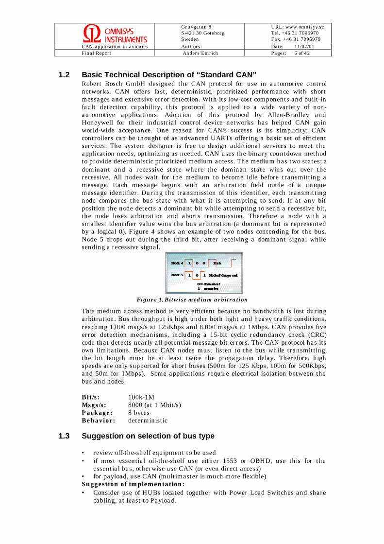
1.2 Basic Technical Description of “Standard CAN”Robert Bosch GmbH designed the CAN protocol for use in automotive controlnetworks. CAN offers fast, deterministic, prioritized performance with shortmessages and extensive error detection. With its low-cost components and built-infault detection capability, this protocol is applied to a wide variety of non-automotive applications. Adoption of this protocol by Allen-Bradley andHoneywell for their industrial control device networks has helped CAN gainworld-wide acceptance. One reason for CAN’s success is its simplicity; CANcontrollers can be thought of as advanced UARTs offering a basic set of efficientservices. The system designer is free to design additional services to meet theapplication needs, optimizing as needed. CAN uses the binary countdown methodto provide deterministic prioritized medium access. The medium has two states; adominant and a recessive state where the dominan state wins out over therecessive. All nodes wait for the medium to become idle before transmitting amessage. Each message begins with an arbitration field made of a uniquemessage identifier. During the transmission of this identifier, each transmittingnode compares the bus state with what it is attempting to send. If at any bitposition the node detects a dominant bit while attempting to send a recessive bit,the node loses arbitration and aborts transmission. Therefore a node with asmallest identifier value wins the bus arbitration (a dominant bit is representedby a logical 0). Figure 4 shows an example of two nodes contending for the bus.Node 5 drops out during the third bit, after receiving a dominant signal whilesending a recessive signal.
Figure 1. Bitwise medium arbitration
This medium access method is very efficient because no bandwidth is lost duringarbitration. Bus throughput is high under both light and heavy traffic conditions,reaching 1,000 msgs/s at 125Kbps and 8,000 msgs/s at 1Mbps. CAN provides fiveerror detection mechanisms, including a 15-bit cyclic redundancy check (CRC)code that detects nearly all potential message bit errors. The CAN protocol has itsown limitations. Because CAN nodes must listen to the bus while transmitting,the bit length must be at least twice the propagation delay. Therefore, highspeeds are only supported for short buses (500m for 125 Kbps, 100m for 500Kbps,and 50m for 1Mbps). Some applications require electrical isolation between thebus and nodes.
Bit/s: 100k-1MMsgs/s: 8000 (at 1 Mbit/s)Package: 8 bytesBehavior: deterministic
1.3 Suggestion on selection of bus type
• review off-the-shelf equipment to be used• if most essential off-the-shelf use either 1553 or OBHD, use this for the
essential bus, otherwise use CAN (or even direct access)• for payload, use CAN (multimaster is much more flexible)Suggestion of implementation:• Consider use of HUBs located together with Power Load Switches and share
cabling, at least to Payload.

Gruvgatan 8S-421 30 GöteborgSweden
URL: www.omnisys.seTel. +46 31 7096970Fax. +46 31 7096979
CAN application in avionics Authors: Date: 11/07/01Final Report Anders Emrich Pages: 7 of 42
2 Logical bus topology
The overall logical bus topology, and the requirements needs to be considered forthe evaluation of suitability of a particular bus type and implementation.
2.1 Number of busesA very early question for the design of satellites is the type and number of busesto use for control and data read-out. It can happen that a decision is made toreduce this, even down to one bus, very early in the design process. The resultfrom this is not only “electrical”, it also involves the overall project organisation,i.e. the organisation structure must reflect how many parties needs to becoordinated.
Based on experience, at least two different buses should be considered, one“essential” and one for the payload. The reason is both organisational andphysical. The essential subsystem is commonly “pure” industrial with itsparticipants, i.e. formal specifications, test procedures etc. In addition, there is alot of re-use from project to project in this area. By contrast, the payload is veryoften a new development for this project with no or very little previousexperience. Furthermore, for science missions, it can be that a large fraction ofthe organisation can be from the university / research institute side with verylimited organisation and qualification for a space project.
The essential side can have more limited data transfer needs compared to thepayload, however, the need for real-time response is obvious in most systems. TheCAN-bus will meet the requirement for most essential systems. The payloadrequirements on the other hand will vary from mission to mission, but it iscommon that a lot of data is transferred to ground for further processing, or in thecase of a communication satellite, there is a lot of data in both directions. Itdepends on the payload, but the CAN bus can meet the requirements for severaltypes as the download bandwidth is often less the CAN bandwidth of some 500kbit/s. The use may require the use of local buffers and/or a different systemplanning and layout.
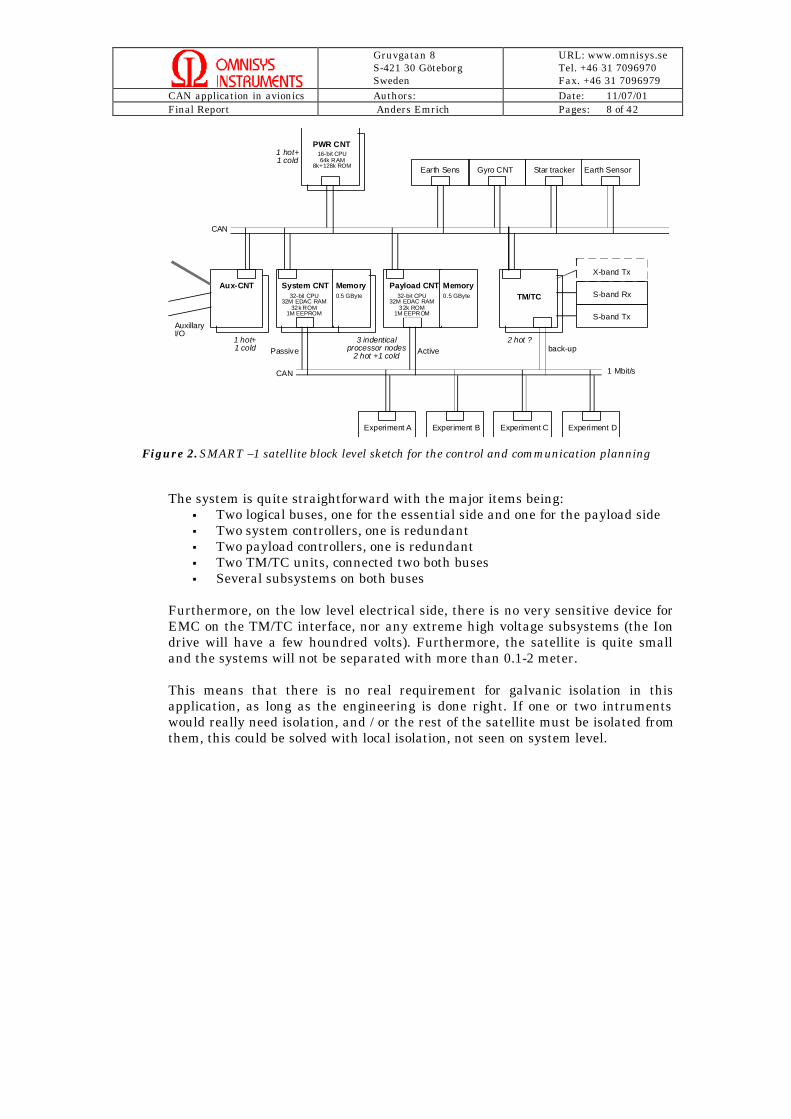
2.2 Example: The SMART-1 type (early)This example is based on very early discussions regarding the SMART-1 satelliteand should not be confused by the real project. The idea is based on a three axisstabilised system incorporating electrical propulsion as well as scientific payload.The essential side has slightly more demands than a fixed satellite.
One possible block solution is in Figure 2.
Gruvgatan 8S-421 30 GöteborgSweden
URL: www.omnisys.seTel. +46 31 7096970Fax. +46 31 7096979
CAN application in avionics Authors: Date: 11/07/01Final Report Anders Emrich Pages: 8 of 42
System CNT
PWR CNT
Aux-CNT Payload CNTMemoryTM/TC
Gyro CNT Star tracker Earth Sensor
Experiment A Experiment B Experiment C Experiment D
32-bit CPU32M EDAC RAM
32k ROM1M EEPROM
CAN
16-bit CPU64k RAM
8k+128k ROM
S-band Tx
S-band Rx
X-band Tx
1 Mbit/s
0.5 GByte
Earth Sens
Memory0.5 GByte
CAN
Passive Active back-up
32-bit CPU32M EDAC RAM
32k ROM1M EEPROM
3 indenticalprocessor nodes
2 hot +1 cold
1 hot+1 cold
1 hot+1 cold
2 hot ?
AuxillaryI/O
Figure 2. SMART –1 satellite block level sketch for the control and communication planning
The system is quite straightforward with the major items being:§ Two logical buses, one for the essential side and one for the payload side§ Two system controllers, one is redundant§ Two payload controllers, one is redundant§ Two TM/TC units, connected two both buses§ Several subsystems on both buses
Furthermore, on the low level electrical side, there is no very sensitive device forEMC on the TM/TC interface, nor any extreme high voltage subsystems (the Iondrive will have a few houndred volts). Furthermore, the satellite is quite smalland the systems will not be separated with more than 0.1-2 meter.
This means that there is no real requirement for galvanic isolation in thisapplication, as long as the engineering is done right. If one or two intrumentswould really need isolation, and / or the rest of the satellite must be isolated fromthem, this could be solved with local isolation, not seen on system level.

Gruvgatan 8S-421 30 GöteborgSweden
URL: www.omnisys.seTel. +46 31 7096970Fax. +46 31 7096979
CAN application in avionics Authors: Date: 11/07/01Final Report Anders Emrich Pages: 9 of 42
3 General Considerations for the use of CAN in space
3.1 Availability of componentsCAN components are presently being used in most new cars and in automatedindustry, which means that the components will continue to be developed and beavailable in the future. The standard devices continue to improve in terms ofEMC, ESD and power consumption.
3.2 Single point failure toleranceThe use of two separate buses will make the system completely single pointfailure tolerant. If only one hub is used, the system is failure tolerant to a numberof single point failures. There is a possibilty to have passive redundancy or active.
3.3 Propagation of local faultA faulty node within a system can ruin the transmission of a whole system, e.g.by occupying all the available bandwidth. The CAN protocol has a built in featurethat prevents a faulty node from blocking the system. A faulty node is eventuallyexcluded from further sending on the CAN bus.
3.4 Error rateThe error handling of CAN is one of the really strong advantages of the protocol.The error detection mechanisms are extensive, and the fault confinementalgorithms are well developed. The error handling and retransmission of themessages is done automatically by the CAN hardware.
3.5 Robustness to random radiation errorsAs indicated above, the error handling of CAN is one of the really strongadvantages of the protocol. Futhermore, if CAN controllers are implemented inFPGA's, you could reduce random radiation errors by standard design methods.However, the reduction of impact of random radiation errors could also behandled on highest system level, if needed.
3.6 Robustness to radiationIf an FPGA is used, there should be no problems with either SEL or total dose formost missions. An Actel SX32 for instance is SEL immune and tolerates 100kRAD and a CAN cores consumes about 50-60 % of the device.
3.7 Robustness to vibrationThe robustness to vibration is not very severe and should be comparable to theuse of standard components, connector and cables. If the CAN controller isimplemented in a FPGA, is will probably have a quite large package thatdominates as the worst component. Special care will have to be taken whenmounting the package, as with any other large component. The use of connectorsand cables will not be more severe compared to other interconnects on thesatellite as few conductors are needed.
If a modern plastic package is used, the potential vibration problems more or lessdisappears for the devices.
3.8 Robustness to temperatureA majority of commercial CAN components (controllers, transceivers) haveoperational temperature ranges between +125° C and -40° C which is withinsatisfactory limits for space applications.
Gruvgatan 8S-421 30 GöteborgSweden
URL: www.omnisys.seTel. +46 31 7096970Fax. +46 31 7096979
CAN application in avionics Authors: Date: 11/07/01Final Report Anders Emrich Pages: 10 of 42
3.9 Real time and hard real timeDue to the priority system used in the CAN protocol, it is possible to ensure lowindividual latency times in real-time systems, even during times of overload.
3.10 Network length and number of nodesThe number of nodes that can be connected to a Controller Area Network is intheory only limited by the number of unique identifiers available (normal CANoffers 2032 identifiers, extended CAN 536870912). In practice however thedriving capabilities of the transceiver circuits limits this. A normal number ofnodes that can be attached to a single bus is between 32 and 64. PhilipsPCA82C250/251 allows for at least 110 nodes to be connected to a single CANnetwork.
At a speed of 1 Mbit/s, a maximum cable length of about 40 meters can be used.This is because the arbitration scheme requires that the wave front of the signalcan propagate to the most remote node and back again before the bit is sampled.In other words, the cable length is restricted by the speed of light.
Other maximum cable lengths are:§ 100 meters at 500 kbit/s§ 200 meters at 250 kbit/s§ 500 meters at 125 kbit/s§ kilometers at 10 kbit/s
3.11 CAN Silicon SolutionsAlmost every major silicon manufacturer (Philips, Intel, Motorola. TexasInstruments, Siemens, etc.) provides CAN chip solutions as standard product.
Controllers: ex. Philips SJA1000, stand aloneIntel 82527, stand alone
Transceivers: ex. Philips PCA82C251 CAN controller interfacePhilips TJA1050 CAN controller interfaceAlcatel MTC-3054 CAN interfaceMotorola MC33388 interface
The Philips TJA1050 is a successor to the PCA82C250 transceiver. The TJA1050has a high Electromagnetic Immunity (EMI) due to a receiver with a widecommon-mode range and a significantly lower Electromagnetic Emission (EME)due to optimal matching of the CANH and CANL output signals.
Gruvgatan 8S-421 30 GöteborgSweden
URL: www.omnisys.seTel. +46 31 7096970Fax. +46 31 7096979
CAN application in avionics Authors: Date: 11/07/01Final Report Anders Emrich Pages: 11 of 42
4 Electrical Interface possibilites
In the paragraphs below, a general overview of different possible electricalrealisations of the CAN bus is shown. This is complemented with more detailedschematics, simulations and protection description, one based on the ISO nongalvanic specification, and one a galvanic transformer isolated implementation. Itshould be noted that latter one must use a "non standard" bit modulationtechnique.
Other possible transmission media, not treated below, are IR and current carriertransmission. There have been special applications and experiments using thesemethods but no widespread general use, as there are several limitations.
4.1 Single and differential wire
The basic operation allows the CAN bus to work with a single wire, however it isnot widely used, nor supported as a physical interface in the ISO11898 standard.It can be considered as a local alternative within a physical unit or for a veryshort distance.
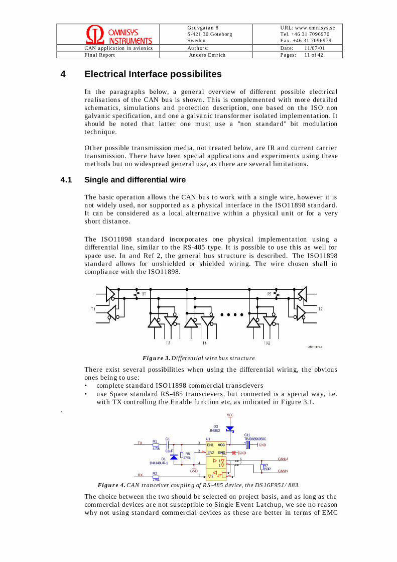
The ISO11898 standard incorporates one physical implementation using adifferential line, similar to the RS-485 type. It is possible to use this as well forspace use. In and Ref 2, the general bus structure is described. The ISO11898standard allows for unshielded or shielded wiring. The wire chosen shall incompliance with the ISO11898.
Figure 3. Differential wire bus structure
There exist several possibilities when using the differential wiring, the obviousones being to use:• complete standard ISO11898 commercial transcievers• use Space standard RS-485 transcievers, but connected is a special way, i.e.
with TX controlling the Enable function etc, as indicated in Figure 3.1..
GND
C1
0.1uFR5
47.5kD11N4148UR-1 7
6
1
2
3
4 1
EN1
2
EN2
1
U1TX
RX
GND
VCC
VCC
GND
R2
4.75k
R1
4.75k
D31N5822
R7150R
CANLA
CANHA
GND
C11TBJD685K050C
Figure 4. CAN tranceiver coupling of RS-485 device, the DS16F95J/883.
The choice between the two should be selected on project basis, and as long as thecommercial devices are not susceptible to Single Event Latchup, we see no reasonwhy not using standard commercial devices as these are better in terms of EMC

Gruvgatan 8S-421 30 GöteborgSweden
URL: www.omnisys.seTel. +46 31 7096970Fax. +46 31 7096979
CAN application in avionics Authors: Date: 11/07/01Final Report Anders Emrich Pages: 12 of 42
and are tougher in terms of overvoltage, apart from being used in multibilliondollar applications. As an exemple, Philips has introduced a transciever based onSOI, which should make it excellent in radiation terms.
Figure 5. Standard CAN architecture
As can be seen in Figure 5, the use of standard transcievers simplifies theelectronics quite a bit, but it is also possible to meet IOS11898 with discretesolutions, as indicated in Figure 6.
Figure 6. The ISO11898 standard High Speed Medium Access Unit
The ISO 11898 standard states that the network terminating resistors used shallhave a nominal value of 120 Ω, a maximum value of 130 Ω, and a minimum valueof 118 Ω. This termination prevents reflected waves on the bus lines and helpsdrive the differential voltage to ~0V during the transmission of recessive bits onthe bus. Every node should be fitted with filtering resistors on the input toprevent reflected waves being superimposed on the signal due to the internalimpedance of the bus transmission lines and the stub connecting the node to thebus wires.

Gruvgatan 8S-421 30 GöteborgSweden
URL: www.omnisys.seTel. +46 31 7096970Fax. +46 31 7096979
CAN application in avionics Authors: Date: 11/07/01Final Report Anders Emrich Pages: 13 of 42
The use of standard devices is still recommended, if formal ESA space standardsare put aside. Some devices are listed in Table 1.
Table 1. Examples of CAN transceivers on the market
It is possible that with a large number of devices on a CAN bus, buffering wouldbe needed and one solution with a repeater is shown in Figure 7.
Figure 7. Block diagram drawing of CAN bus repeater
A repeater is a device that electrically buffers two bus sections from each other,allowing more CAN nodes to be connected to one bus. On the other hand, the useof repeaters limits the maximum baudrate and/or the maximum physical buslength, since they introduce a delay between each bus section.
However, it is strongly advised by Omnisys to look again at the complete systemdesign again, it seems likely this should be solved on a higher level.
4.2 Galvanic IsolationGalvanic isolation of electrical units in a system is used to eliminate internalground loops, increase the noise immunity of a system, reduce effects of electricalnoise, and protect equipment and user should the unit or something in itssurroundings malfunction. Isolation is also an important way to prevent staticand most kinds of damaging surges in data communications systems.
4.2.1 No IsolationWith no isolation the units on the CAN network is directly connected to the bus-line, and it is difficult to prevent the propagation of ground loops, transients, andother disturbances in the system. The resulting reduction in components whenopting for a non-isolated system in a satellite with a large network reducesoverall spacecraft cost and mass in a not insignificant way.

Gruvgatan 8S-421 30 GöteborgSweden
URL: www.omnisys.seTel. +46 31 7096970Fax. +46 31 7096979
CAN application in avionics Authors: Date: 11/07/01Final Report Anders Emrich Pages: 14 of 42
The non isolated interface is also the most widely used, which is a very strongargument, both for access to robust devices, but also for design, testing andverification.
4.2.2 Optic IsolationOptic isolation is commonly used when galvanic isolation is required. However,the use of optic isolators in space requires extra thinking and consideration. Opticisolators are ”energy detectors” and thus susceptible to both radiation singleevent effects and total dose. Optic isolation of circuitry is not supported by theISO11898 standard.
Figure 8. Galvanic isolation using opto couplers
Fibre optics are inherently immune to electrical and magnetic interference, andthe integration cost due to interference and cross-talk discovered duringintegration is virtually zero. Additional benefits of using fiber optics are weightreduction due to decreased electrical wire usage, and increased data ratecapabilities. To this date it is however unknown how radiation will affect theoptic fibre (darkening etc) when exposed to radiation during a deep-spacemission. Due to the relatively recent development of fibre applications suitable forspace there is a limited number of mature procedures and flight-qualifiedcomponents available.
Figure 9. Opto couplers on all nodes
In Figure 9, a design is indicated with optocouplers on all nodes in the system.This would add a not insignificant number of devices with potential radiationproblems, from SEU, SEL to total dose effects.
Figure 10. Opto couplers only when needed

Gruvgatan 8S-421 30 GöteborgSweden
URL: www.omnisys.seTel. +46 31 7096970Fax. +46 31 7096979
CAN application in avionics Authors: Date: 11/07/01Final Report Anders Emrich Pages: 15 of 42
In figure 10, the solution with a few opto couplers is indicated, which is preferedand should only be used when absolutly necessary. If the opto couplermissbehaves, it is possible to shut the complete device down and still operate thebus, i.e. the need for the isolation is device specific and device solved.
4.2.3 Transformer Isolation (bi-phase modulation)This is supported by very early CAN-circuits but not used to any extend. Theunits on the network are protected by a transformer that effectivly shields theunits from unwanted noise and potentially dangerous disturbances. The use of aNRZ signalling scheme in CAN introduces a problem when using transformerisolation in a circuit. A transformer in which a signal of one and the same level istransmitted builds an magnetic flux in the core. This field can only reach a setvalue before the core suffers a breakdown and effectively short circuits theprimary and secondary windings of the transformer. To prevent the electric fieldfrom reaching this level in case a long stream of ’1’s or ’0’s is transmitted, thetransformer can be reset by transmitting a signal of opposite polarity (ACsignalling) or by letting it reset by itself by dissipation of the electric field over aperiod of time. The latter method is obviously not applicable when dealing withbit rates of 1 Mb/s. The active resetting can be achieved both in software solutionsand discrete hardware solutions.

Gruvgatan 8S-421 30 GöteborgSweden
URL: www.omnisys.seTel. +46 31 7096970Fax. +46 31 7096979
CAN application in avionics Authors: Date: 11/07/01Final Report Anders Emrich Pages: 16 of 42
4.3 Electrical TopologyThe number of nodes that can be connected to a Controller Area Network is intheory only limited by the number of unique identifiers available (normal CANoffers 2032 identifiers, full CAN offers 536870912). In practice however thedriving capabilities of the transceiver circuits limits this. A normal number ofnodes that can be attached to a single bus is between 32 and 64. PhilipsPCA82C250/251 allows for at least 110 nodes to be connected to a single CANnetwork.
4.3.1 ISO 11898 solutionThe ISO 11898 dictates that the topology of the CAN network should be as closeas possible to a single line structure (this to avoid reflected waves). In practiceshort stubs are used to connect the different units to the bus line. The CANprotocol is developed with such a topology in mind.
4.3.2 Hub based topologyThere is an alternative that could potentially increase the integrity of the bus,but most of all it would simplify the system integration and test and that is to usea central hub and where each subsystem is connected to it and not to the otherunits. The CAN protocol does not inherently support this kind of topology.
Figure 11. Block level drawing of a hub based realization of the CAN bus

Gruvgatan 8S-421 30 GöteborgSweden
URL: www.omnisys.seTel. +46 31 7096970Fax. +46 31 7096979
CAN application in avionics Authors: Date: 11/07/01Final Report Anders Emrich Pages: 17 of 42
5 Tranceiver Realisation examples
5.1 Discrete realisation of the ISO non galvanic interfaceThe task is to design a non isolated CAN tranceiver, complient with the ISOspecification, based on available HiRel components. There exist alternatives forall components, but the types shown and listed should be available. A suggesteddesign is shown in Figure 12, which also includes protection against producingovervoltage on the bus.
U1ALM193
Q52N2369
Q12N5771
R31k
C3
10n
Q42N2369
R11330
R11k
R12
4.7
R13
4.7
R727k
R827k
D3BAS40
D2
BAS40
D5
BAS40
D4
BAS40
Vcc Vcc
R10
4.7kTx
Rx
VccVcc
R41k
R192.7k
R202.7k
CAN high
CAN low
R212.7k
R222.7k
VccVcc
R17
470k
R18150k
C1
10n
Figure 12. Non isolated CAN tranceiver design.
Design details:
The delay in/out of the drivers is determined by the selection of both the bipolartransistors and by the comparators used in the receivers. The selected devices inthe schematics shown in Figure 12 allows for 1 Mbit/s transmission and morethan 30 nodes.
Transmitter delay: 30nsReceiver delay: 70nsOutput impedance: 10ohmInput impedance: 56kohmTransmitter level: 2.7VReceiver threshold: 400mV ± 120mV
Because of the nature of the CAN bus, where dominant bits are driven activelyand recessive bits are not, the recessive bits will always cause moretransmitter/receiver delays than dominant bits. The figures given for thetransceiver delays are worst case, i.e. those for dominant to recessive transition.
One of the most critical aspects in most systems, if based on two redundant buses,would be to protect the system from different types of power supply faults,triggered by the tranciever. In figure 13, a safe tranceiver supply is shown,protected against overvoltage and with current limitation.

Gruvgatan 8S-421 30 GöteborgSweden
URL: www.omnisys.seTel. +46 31 7096970Fax. +46 31 7096979
CAN application in avionics Authors: Date: 11/07/01Final Report Anders Emrich Pages: 18 of 42
D 11N4626
D31N5314
Q42N2222ACSM
Q 52N2222ACSM
R3
470k
R2470k
R1210k
R147k
R427k
D21N4626
D41N5968
C410n
Q32N2222ACSM
C3100n
Vcc
R51k
R930
U12V
GND
Q22N2907ACSM
Q1
2N29
07A
CSM
Figure 13. Power supply for the tranceiver.
5.1.1 Transmission line simulationsWe have selected to present three simulations:
1
2
3
4
500N 1.50U 2.50U 3.50U 4.50U
WFM.4 UREC vs. TIME in Secs
18.0
14.0
10.00
6.00
2.00
UR
EC
in V
olts
12.0
8.00
4.00
0
-4.00
1
2
3
4
500N 1.50U 2.50U 3.50U 4.50U
WFM.4 UREC vs. TIME in Secs
18.0
14.0
10.00
6.00
2.00
UR
EC
in V
olts
12.0
8.00
4.00
0
-4.00
1
2
3
4
500N 1.50U 2.50U 3.50U 4.50U
WFM.4 UREC vs. TIME in Secs
18.0
14.0
10.00
6.00
2.00
UR
EC
in V
olts
12.0
8.00
4.00
0
-4.00
Figure 14. Simulation with the three different set-ups: 5 m cable with nominaltermination, 30 m cable with nominal termination and cable with 80 ohm instead of 120
ohm termination. The top trace show driver input signal, the second the driver outputsignal, the third the receiver input signal, and the last, the receiver output signal.
The result is shown in Figure 14, that indicates that even with 30 m cable lengthand with "faulty" termination, the signal transmission is perfect after reception.
5.1.2 Common mode simulationsThe common mode rejection simulation is relevant for non isolated designs.Depending on overall electrical design of a satellite, different problems and levelscould be expected. With a reasonalble size satellite, lets say maximum distance of2 m, and good electrical design, only a couple of volts can be expected in commonmode difference between nodes.
The result from simulations shows common rejection from -11 V to +34 V, whichshould be sufficient for almost all applications.

Gruvgatan 8S-421 30 GöteborgSweden
URL: www.omnisys.seTel. +46 31 7096970Fax. +46 31 7096979
CAN application in avionics Authors: Date: 11/07/01Final Report Anders Emrich Pages: 19 of 42
5.1.3 RF noise susceptibility
1
2500N 1.50U 2.50U 3.50U 4.50U
WFM.2 UREC vs. TIME in Secs
18.0
14.0
10.00
6.00
2.00
UR
EC
in V
olts
10.00
0
-10.00
-20.0
-30.0
1
2500N 1.50U 2.50U 3.50U 4.50U
WFM.2 UREC vs. TIME in Secs
18.0
14.0
10.00
6.00
2.00
UR
EC
in V
olts
10.00
0
-10.00
-20.0
-30.0
1
2500N 1.50U 2.50U 3.50U 4.50U
WFM.2 UREC vs. TIME in Secs
18.0
14.0
10.00
6.00
2.00
UR
EC
in V
olts
10.00
0
-10.00
-20.0
-30.0
Figure 15. Noise with 100kHz, 1 MHz and 10 MHz, 10 V rms applied. No sensitivity canbe seen.
The simulation show no design problems with RF susceptibility, but this shouldbe complemented with real world testing for a particular implementation, is it isdependent to a large degree on cable and connector imperfections.
5.1.4 AvailabilityThere should be no problems in availability of suitable components, allcomponents used are available in MIL883 and or QMLQ and most could beattained with at QMLV, if so required. However, with lead time etc., it could besmart to change type on the diodes and transistors, there exist similar devicesthat could be easier to optain for a specific project.
5.1.5 Single point failure toleranceThe use of two separate buses will make the system completely single pointfailure tolerant. There is a possibilty to have passive redundancy or active.
5.1.6 Propagation of local faultA faulty node within a system can ruin the transmission of a whole system, e.g.by occupying all the available bandwidth. This could be handled in various ways,but is a system level question, i.e. not only related to the bus tranceiver.
5.1.7 Error rateThe error handling of CAN is one of the really strong advantages of the protocol.The error detection mechanisms are extensive, and the fault confinementalgorithms are well developed. The error handling and retransmission of themessages is done automatically by the CAN hardware.
5.1.8 Robustness to radiationMore of a matter for the control device, but it shoul be noted that the errorchecking in the CAN protocoll is very strong, and random errors should onlyresult in retransmission of one CAN package.With the design shown, there should be no problems with either SEL or total dosefor most missions, at least 30-100 kRAD total dose tolerance could be expected,depending on components used.
5.1.9 Robustness to vibration and temperatureThe robustness to vibration is not very severe and should be comparable to theuse of standard components, connector and cables.
There should be no difference compared to other electronic circuits as the sametype of components is used.

Gruvgatan 8S-421 30 GöteborgSweden
URL: www.omnisys.seTel. +46 31 7096970Fax. +46 31 7096979
CAN application in avionics Authors: Date: 11/07/01Final Report Anders Emrich Pages: 20 of 42
5.2 Transformer isolated CAN interfaceIn contrast to the normal output mode the bit representation is time variant andtoggled. If the bus controllers are galvanically decoupled from the bus line by atransformer, the bit stream is not allowed to contain a DC component. This isachieved by the following scheme.
During recessive bits all outputs are deactivated (floating), indicated in Figure 21by grey areas. Dominant bits are sent with alternating levels on TX0 and TX1, i.e.the first dominant bit is sent on TX0, the second is sent on TX1, and the third oneis sent on TX0 again, and so on. One possible configuration example of the bi-phase output mode timing is shown in Fig.16.
Figure 16. Bi-phase modulation.
A transformer isolated CAN tranceiver design is shown in Figure 17, andTX0/TX1 is used as indicated in Figure 16. It is based on discrete components andthere should be no availability problems. The design is based on a standardtransformer design, but this must be ordered as a custom product, depending onboth real physical aspects, such as size, and on formal quality aspects used for aparticular project.
Transmitter delay: 60nsReceiver delay: 70nsOutput impedance: 10ohmInput impedance: 35kohmTransmitter level: +/- 4VReceiver threshold: 3.15V ± 20mV
Because of the nature of the CAN bus, where dominant bits are driven activelyand recessive bits are not, the recessive bits will always cause moretransmitter/receiver delays than dominant bits. The figures given for thetransceiver delays are worst case, i.e. those for dominant to recessive transition.

Gruvgatan 8S-421 30 GöteborgSweden
URL: www.omnisys.seTel. +46 31 7096970Fax. +46 31 7096979
CAN application in avionics Authors: Date: 11/07/01Final Report Anders Emrich Pages: 21 of 42
Q7BC817
R1210
Q8BC817
R1310
R81k
D7
BAS40D6BAS40
Tx0
Vcc
L1TRANS_1_2
D5BAS40 D8
BAS40
R101.5k
R111.5k
R9
1k
C3
100n
Tx1
Rx
U1ALM193
C4
10n
VccVcc
R201k
R182.2k
R172.2k
R1622k
R1527k
VccVcc
R19
1M
R1422k
Figure 17. Transformer isolated CAN tranceiver design.
One of the most critical aspects in most systems, if based on two redundant buses,would be to protect the system from different types of power supply faults,triggered by the tranciever. In figure 18, a safe tranceiver supply is shown,protected against overvoltage and with current limitation.
D11N4626
D31N5314
Q42N2222ACSM
Q52N2222ACSM
R3
470k
R2470k
R410k
R147k
R527k
D21N4626
D41N5968
C110n
Q32N2222ACSM Vcc
R61k
R730
U12V
GND
Q22N2907ACSM
Q1
2N29
07A
CSM
Figure 18. Power supply for the tranceiver.

Gruvgatan 8S-421 30 GöteborgSweden
URL: www.omnisys.seTel. +46 31 7096970Fax. +46 31 7096979
CAN application in avionics Authors: Date: 11/07/01Final Report Anders Emrich Pages: 22 of 42
5.2.1 Transmission line simulationsWe have selected to present three simulations:
1
2
3
4
5
1.00U 3.00U 5.00U 7.00U 9.00UWFM.5 URXT vs. TIME in Secs
42.0
32.0
22.0
12.0
2.00
UR
XT
in V
olts
30.0
20.0
10.00
0
-10.00
CA
NTE
RM
in V
olts
1
2
3
4
5
1.00U 3.00U 5.00U 7.00U 9.00UWFM.5 URXT vs. TIME in Secs
42.0
32.0
22.0
12.0
2.00
UR
XT
in V
olts
30.0
20.0
10.00
0
-10.00
CA
NTE
RM
in V
olts
1
2
3
4
5
1.00U 3.00U 5.00U 7.00U 9.00UWFM.5 URXT vs. TIME in Secs
42.0
32.0
22.0
12.0
2.00
UR
XT
in V
olts
30.0
20.0
10.00
0
-10.00
CA
NT
ER
M in
Vol
ts
Figure 19. Simulation with three different set-ups: 5 m cable with nominal termination,30 m cable with nominal termination and cable with 80 ohm instead of 120 ohm
termination. The top two traces show driver input signals, the third the driver outputsignal, the fourth, the receiver input signal and the last, the detected signal.
The result is shown in Figure 19, that indicates that even with 30 m cable lengthand with "faulty" termination, the signal transmission is perfect after reception.
5.2.2 RF noise susceptibilityThe RF noise susceptibility simulation set-up is shown in Figure 20 .
1
3
2
10.00U 30.0U 50.0U 70.0U 90.0UWFM.2 URX vs. TIME in Secs
4.00
2.00
0
-2.00
-4.00
UR
X in
Vol
ts
6.00
4.00
2.00
0
-2.00
UR
XT
in V
olts
1
2
3
1.00U 3.00U 5.00U 7.00U 9.00UWFM.3 URXT vs. TIME in Secs
6.00
4.00
2.00
0
-2.00
UR
XT
in V
olts
4.00
2.00
0
-2.00
-4.00
UR
X in
Vol
ts
1
2
3
1.10U 1.30U 1.50U 1.70U 1.90UWFM.3 URXT vs. TIME in Secs
6.00
4.00
2.00
0
-2.00
UR
XT
in V
olts
4.00
2.00
0
-2.00
-4.00
UR
X in
Vol
ts
Figure 20. Noise with 100kHz, 1 MHz and 10 MHz, 10 V rms applied. No sensitivity canbe seen.
The simulation show no design problems with RF susceptibility, but this shouldbe complemented with real world testing for a particular implementation, is it isdependent to a large degree on cable and connector imperfections.
5.2.3 AvailabilityFor the transformer, this must be ordered separately from a qualified source, butfor the other components, there should be no problems in availability, allcomponents used are available in MIL883 and or QMLQ and most could beattained with at QMLV, if so required. However, with lead time etc., it could besmart to change type on the diodes and transistors, there exist similar devicesthat could be easier to optain for a specific project
5.2.4 Single point failure toleranceThe use of two separate buses will make the system completely single pointfailure tolerant. There is a possibilty to have passive redundancy or active.
5.2.5 Propagation of local faultA faulty node within a system can ruin the transmission of a whole system, e.g.by occupying all the available bandwidth. This could be handled in various ways,but is a system level question, i.e. not only related to the bus tranceiver.

Gruvgatan 8S-421 30 GöteborgSweden
URL: www.omnisys.seTel. +46 31 7096970Fax. +46 31 7096979
CAN application in avionics Authors: Date: 11/07/01Final Report Anders Emrich Pages: 23 of 42
5.2.6 Error rateThe error handling of CAN is one of the really strong advantages of the protocol.The error detection mechanisms are extensive, and the fault confinementalgorithms are well developed. The error handling and retransmission of themessages is done automatically by the CAN hardware.
5.2.7 Robustness to radiationMore of a matter for the control device, but it shoul be noted that the errorchecking in the CAN protocoll is very strong, and random errors should onlyresult in retransmission of one CAN package.
With the design shown, there should be no problems with either SEL or total dosefor most missions, at least 30-100 kRAD total dose tolerance could be expected,depending on components used.
5.2.8 Robustness to vibration and temperatureThe robustness to vibration is not very severe and should be comparable to theuse of standard components, connector and cables.
There should be no difference compared to other electronic circuits as the sametype of components is used.

Gruvgatan 8S-421 30 GöteborgSweden
URL: www.omnisys.seTel. +46 31 7096970Fax. +46 31 7096979
CAN application in avionics Authors: Date: 11/07/01Final Report Anders Emrich Pages: 24 of 42
5.3 Standard ISO implementation based on TJA1050The TJA1050 is the successor to the PCA82C250 high-speed CAN transceiver.The most important improvements are:• Much lower electromagnetic emission due to optimal matching of the output
signals CANH and CANL• Improved behaviour in case of an unpowered node (unpowered modes
supported by other devices as well)
Features• Fully compatible with the "ISO 11898" standard• High speed (up to 1 Mbaud)• Very low ElectroMagnetic Emission (EME)• Differential receiver with wide common-mode range for high ElectroMagnetic
Immunity (EMI)• An unpowered node does not disturb the bus lines• Transmit Data (TXD) dominant time-out function• Silent mode in which the transmitter is disabled• Bus pins protected against transients in an automotive environment• Input levels compatible with 3.3 V devices• Thermally protected• Short-circuit proof to supply voltage and ground• At least 110 nodes can be connected.
5.3.1 BCD/SOI technologyFrom Philips:
Philips Semiconductors' first SOI Smart Power process technology is called A-BCD1 (Advanced Bipolar-CMOS-DMOS) - a single-poly, double-metal technologytargeted for 12 V to 60 V applications - combining bipolar, CMOS and DMOS. Thetechnology uses a 1.5 µm active silicon layer on top of a 1 µm layer of buriedoxide.
The oxide layer allows for complete isolation of all components formed on the chipand offers four key advantages as a result:
• reduced resistance when its transistors are in the on-state
• the absence of junctions between N- and P-type devices and the substrate
• much greater packing densities can be achieved
• parasitic capacitances are significantly reduced
These four factors lead to numerous advantages. Firstly, by decreasing theresistance Rds (on) by up to 20 %, A-BCD1 generates far less heat thanequivalent bulk silicon processes, reducing or eliminating the need for heat sinksand keeping costs down. And with this low Rds (on) , SOI gives DMOS transistorsexcellent power handling capabilities, allowing designers to choose for the samesize of chip of lower heat dissipation, or higher current handling ability, or asmaller chip with the same dissipation. The end result of this choise has, in oneexample, allowed stand-by power consumption to be reduced.
Secondly, with no junctions between the n- and p-type devices and the substrate,SOI is intrinsically free from latch-up (associated with the overloading of bulksilicon transistors) and virtually eliminates problems arising from cross-talk viathe substrate, load dump and other accidental high external voltages. Thesefeatures make SOI inherently reliable and also allow for easy integration ofmultiple power devices, bridge rectifiers and flyback diodes on the same piece ofsilicon. When combined with CMOS, Bipolar, JFET and DMOS SOI devices, theseadvantages enable the creation of real smart power circuits.

Gruvgatan 8S-421 30 GöteborgSweden
URL: www.omnisys.seTel. +46 31 7096970Fax. +46 31 7096979
CAN application in avionics Authors: Date: 11/07/01Final Report Anders Emrich Pages: 25 of 42
Thirdly, the packing densities achieved by SOI represent a major advance on bulksilicon, enabling size reductions of up to 30 %: next generation A-BCD2 (EZ-HV)devices should be able to improve on this still further, as well as offering evenlower Rds (on).
Lastly, many of SOI's advantages come from the isolation of the components inthe oxide layer, ensuring excellent insulation and, as a result, a significantreduction in parasitic capacitances, leading to quicker and easier design-in.Eliminating latch-up and parasitics provides other benefits as well, such asprotection from voltage spikes. Because A-BCD1 does not need reverse-biasedjunctions to isolate components, leakage currents are avoided and so SOI hasmuch greater heat tolerance, up to 160 °C instead of the normal 125 °C for bulksilicon.
Comments from Omnisys:
The use of SOI technology should remove two of the radiation problems ofintegrated circuits, the Total Dose degradation and the Single Event Latch-up,but this should be verified by either analyses or test. Furthermore, theprobability of other types of single event faults should be reduced.
As Philips is likely not to share information about their process, testing will beneeded in that case.
5.3.2 AvailabilityVolume production is now running. Philips have some 80 % of the market sharefor CAN bus tranceivers (Anders Lundquist, Mecel, verbal communication), andwhile most systems now are based on "older" devices most new projects aredesigned around the TJA1050.
The TJA1050 is available in plastic SO-8 in commercial and automotiv grade, andas tested but not screened naked die.
Minimum, quoted volume, is 1000 devices for packaged devices and 2000 fornaked die (Promax). The packaged devices should be available with smallermiminum volume shortly through other distributors. The cost is about 1 ECU perdevice, naked as well as packaged.
5.3.3 Single point failure toleranceA current-limiting circuit protects the transmitter output stage from damagecaused by accidental short-circuit to either positive or negative supply voltage,although power dissipation increases during this fault condition.
A thermal protection circuit protects the IC from damage by switching off thetransmitter if the junction temperature exceeds a value of approximately 165 °C.Because the transmitter dissipates most of the power, the power dissipation andtemperature of the IC is reduced. All other IC functions continue to operate. Thetransmitter off-state resets when pin TXD goes HIGH. The thermal protectioncircuit is particularly needed when a bus line short-circuits.
The pins CANH and CANL are protected from automotive electrical transients(according to “ISO 7637”).
The use of two separate buses will make the system completely single pointfailure tolerant.
The tranceiver "bus off" mode can help in the implementation of differentredundant schemes as well as the high impedance when in power down mode.
In the silent mode, the transmitter is disabled. All other IC functions continue tooperate. The silent mode is selected by connecting pin S to VCC. This mode can be

Gruvgatan 8S-421 30 GöteborgSweden
URL: www.omnisys.seTel. +46 31 7096970Fax. +46 31 7096979
CAN application in avionics Authors: Date: 11/07/01Final Report Anders Emrich Pages: 26 of 42
used by nodes that don't need to send any data, but can also be used to preventnetwork communication from being blocked etc,
5.3.4 Propagation of local faultA faulty node within a system can ruin the transmission of a whole system, e.g.by occupying all the available bandwidth.
The TJA1050 incorporate some protection against completely faulty CANmessages through a timer, checking that the node is not stuck on Dominant.
A ‘TXD dominant time-out’ timer circuit prevents the bus lines being driven to apermanent dominant state (blocking all network communication) if pin TXD isforced permanently LOW by a hardware and/or software application failure. Thetimer is triggered by a negative edge on pin TXD. If the duration of the LOW-level on pin TXD exceeds the internal timer value, the transmitter is disabled,driving the bus into a recessive state. The timer is reset by a positive edge on pinTXD.
5.3.5 Error rate and robustness to random radiation errorsAs indicated in 4.8, the error handling of CAN is one of the really strongadvantages of the protocol.
The TJA1050 has also improved electrical behavior in several areas that reducethe error rate, such as 20 dB improvement in EMC, wider commen mode rangeand perhaps most importanly, the use of SOI technology should reduce theprobability of single event errors induced by radiation, but this should be verified.
5.3.6 Robustness to radiationIf an TJA1050 is used, because of the SOI technology, there should be noproblems with either SEL or total dose for most missions.
5.3.7 Robustness to vibration and temperatureThe robustness to vibration is not very severe and should be comparable to theuse of standard components, connector and cables. If a modern plastic package isused, the potential vibration problems more or less disappears for the devices.
A majority of commercial CAN components (controllers, transceivers) haveoperational temperature ranges between +125° C and -40° C which is withinsatisfactory limits for space applications. This also applies to the TJA1050
5.3.8 Network length and number of nodesThe TJA1050 can be used with up to 110 nodes. The network length is dependentboth on cable type and number of nodes, but the use of TJA1050 should match orimprove on existing designs.
The number of nodes, which can be connected to a bus, depends on the minimumload resistance a transceiver is able to drive. The TJA1050 transceiver providesan output drive capability down to a minimum load of RL.min = 45W for VCC >4.75V. The overall bus load is defined by the termination resistance RT, the busline resistance RW and the transceiver´s differential input resistance Rdiff. WithRT of 118 ohm, this gives 131 nodes, and with RT of 130 ohm, this gives 170nodes.
The maximum achievable bus line length in a CAN network is determinedessentially by the following physical effects:

Gruvgatan 8S-421 30 GöteborgSweden
URL: www.omnisys.seTel. +46 31 7096970Fax. +46 31 7096979
CAN application in avionics Authors: Date: 11/07/01Final Report Anders Emrich Pages: 27 of 42
1. The loop delays of the connected bus nodes (CAN controller, transceiver etc.)and the delay of the bus line
2. The relative oscillator tolerance between nodes
3. The signal amplitude drop due to the series resistance of the bus cable andthe input resistance of bus nodes.
Effects 1 and 2 determine a value for the maximum bus line length with respectto the CAN bit timing. Effect 3, on the other side, determines a value with respectto the output signal drop along the bus line. The minimum of the two values hasto be taken as the actual maximum allowable bus line length. As the signal dropis only significant for very long lengths, effect 3 can often be neglected for highdata rates.
A data rate of 500 kbit/s gives a maximum length of 107 m. The calculation isbased on effects 1 and 2 assuming an oscillator tolerance of better than 0.15%.Notice that the stated values apply only for a well terminated linear topology.Bad signal quality because of improper termination can lower the maximumallowable bus length.
For most satellite applications, 1 Mbit data rate should not be any problem, asthe most often better crystals are used and 30 m cabling would be considered verylong.
5.3.9 Other aspectsTransmission lines must be terminated with the characteristic line impedance,otherwise signal reflections will occur on the bus causing significant ringing. Thetopology has to be chosen such that reflections will be minimized. Often thetopology is a trade-off between reflections and wiring constraints.
CAN is well prepared to deal with reflection ringing due to some useful protocolimplementations:
1. Only recessive to dominant transitions are used for resynchronization.
2. Resynchronization is allowed only once between two sample points, and onlyif a recessive bit was sampled.
The sample point is programmable to be close to the end of the bit time.
Gruvgatan 8S-421 30 GöteborgSweden
URL: www.omnisys.seTel. +46 31 7096970Fax. +46 31 7096979
CAN application in avionics Authors: Date: 11/07/01Final Report Anders Emrich Pages: 28 of 42
5.4 Tranceiver Realisation ConclusionsThe CAN protocol has been around for close to fifteen years, and although it wasdesigned for automotive applications (which still is the main area of use for CAN),the CAN protocol has been widely accepted in many industrial non-automotiveapplications as well. This is much thanks to its low cost, high performance, andthe availability of various CAN-protocol implementations. The CAN protocol hasfour major benefits. (1), A standard communications protocol simplifies andeconomizes the interfacing of user subsystems onto a shared network. (2) Thework load is shifted from the host-CPU to an intelligent peripheral; which leavesthe host-CPU with more time to run its essential system tasks. (3) As amultiplexed network, a CAN-bus greatly reduces wire harness size andeliminates point-to-point wiring. (4) CAN has broad market appeal, and thismotivates semiconductor developers to design competitively priced CAN chips.
Using COTS in space is desirable, as the use of commercial components greatlyreduces the cost and procurement time during a project. CAN was primarilydeveloped for the use in cars, and this further supports the idea of using CANcomponents in space applications. This as the electrical and noise environment ina car is by far much harsher than that of a satellite. After studying the existingsolutions for the CAN-bus, a differential signalling scheme on a standard busstructure in compliance with the ISO11898 standard is suggested for satelliteapplications. The ISO11898 leaves the choice of galvanic isolation undefined, butthe use of transformer isolation to prevent the propagation of earth loops,transients, and other disturbances in the system is a possibilty that could beconsidered. The use of other designs, such as a hubbed bus topology or opticisolation should however not be completely discarded as there might be situationswhere this might be suitable.
5.4.1 Proposal A: non galvanic isolationWe strongly propose to use the ISO11898 standard with commercial transcievers.There is a multibillion dollar industri to back this up. This means that there is avast access to devices, development systems, tools etc. but also to skilledengineers.
5.4.2 Proposal B2: galvanic isolationIf needed, and if all nodes need isolation, you could consider transformer isolationof the nodes.

Gruvgatan 8S-421 30 GöteborgSweden
URL: www.omnisys.seTel. +46 31 7096970Fax. +46 31 7096979
CAN application in avionics Authors: Date: 11/07/01Final Report Anders Emrich Pages: 29 of 42
6 System Redundancy
One important aspect is different redundancy concepts for the bus hardware. Wediscuss two concepts; warm and cold redundancy setup operates, both withmajority voting.
One alternative is described each for the cold and warm redundancy, severaloptions exist in both cases, but this can be useful as examples.
6.1 Cold Redundancy
The basic system idea:§ Single CAN core in each node
§ Dual transceivers in each node
§ Watchdog in each node, possible to override from local CPU
§ Watchdog is reset through special CAN message
§ When the watchdog times out, the CAN node toggles to the other
transceiver.
§ Watchdog times out after one time unit
CPU:A CPU:B CPU:C
PWR:A PWR:B PWR:C
TC:A
TC:B
TM:A
TM:B
Figure 21. System bus overview. Logical Bus only.
Start-up Sequence§ Possible TC on
§ The PWR units power up CPU:A
§ Waits for CPU:A OK, 10 time units
§ CPU:A tries bus A 5 time units, bus B 5 time units
§ The PWR units shuts down CPU:A, powers up CPU:B
§ CPU:B tries bus A 5 time units, bus B 5 time units
§ Cycle can continue, i.e. A-B-C, send TC, A-B-C etc.
§ If CPU:X starts, it transmits Watchdog Reset signal on the established
bus
§ CPU:X sends PWR ON commands to PWR:A,B,C for the different sub-
systems

Gruvgatan 8S-421 30 GöteborgSweden
URL: www.omnisys.seTel. +46 31 7096970Fax. +46 31 7096979
CAN application in avionics Authors: Date: 11/07/01Final Report Anders Emrich Pages: 30 of 42
When the Master CPU has turned on the sub-systems, it checks the operation ofeach device, for example demanding ‘I am OK’ for each within a certain period oftime. If any device does not respond, the Master CPU can decide to tryestablishing contact on the redundant bus. After the initial check the MasterCPU can relinquish bus monitoring to the individual nodes by transmitting aperiodical Watchdog Reset signal to every node on the established bus. The buscommunication can fail due to either a physical problem (such as a break, or by abus wire short to either ground or supply voltage), however a bus switch mightalso be recommended if failures of for example the CAN transceivers located inone of the nodes occur.
Bus Failure 1
1. CPU:X stops transmitting Watchdog Reset signal to PWR:ABC on BUS:X dueto failure of CAN transceiver or CAN controller.
2. The system goes to start-up again (see Start-up Sequence).
Bus Failure 2
1. BUS:X is broken between CPU:X and PWR:ABC2. The Watchdog Reset signal is lost and the system goes to start-up again.
Communication will be established on non-broken bus
Bus Failure 3
1. BUS:X is broken between CPU:X and TC:A2. Watchdog Reset signal is lost and TC:A starts toggling between buses, TC:B
can possibly still be used3. Master CPU is monitoring BUS:Y and detects traffic.4. Master CPU transfers TC:A back to BUS:X to make sure the transfer not was
provoked by a transient problem, either by not transmitting a Watchdog Resetsignal on BUS:Y or by transmitting a forcing CAN message.
5. If Master CPU decides to switch bus, the Watchdog Reset signal on BUS:X isterminated and transferred to BUS:Y.
6. All sub-systems will establish contact with BUS:Y.
Bus Failure 4
1. BUS:X is broken between CPU:X and Node:X.2. The Watchdog Reset signal is lost and Node:X toggles to BUS:Y3. Master CPU detects traffic on BUS:Y4. Master CPU transfers Node:X back to BUS:X to make sure the transfer not
was provoked by a transient problem.5. If Master CPU decides to switch bus, the Watchdog Reset signal on BUS:X is
terminated and transferred to BUS:Y.6. All sub-systems will establish contact with BUS:Y
Bus Failure 5
1. Node:X stops receiving Watchdog Reset signal on BUS:X, due to CANtransceiver or CAN controller failure.
2. Node:X toggles to BUS:Y3. Master CPU detects traffic on BUS:Y4. Master CPU transfers Node:X back to BUS:X to make sure the transfer not
was provoked by a transient problem, either by not transmitting a WatchdogReset signal on BUS:Y or by transmitting a forcing CAN message.
5. If Master CPU decides to switch bus, the Watchdog Reset signal on BUS:X isterminated and transferred to BUS:Y.
6. All sub-systems will establish contact with BUS:Y
Gruvgatan 8S-421 30 GöteborgSweden
URL: www.omnisys.seTel. +46 31 7096970Fax. +46 31 7096979
CAN application in avionics Authors: Date: 11/07/01Final Report Anders Emrich Pages: 31 of 42
Bus Failure 6
1. BUS:X is shorted to ground or supply voltage2. All users on the bus will detect form errors, bit stuffing violations, and errors
in the reception of self-transmitted messages. This will prompt them totransfer communications to BUS:Y.
3. The Master CPU transfers the users back to BUS:X to make sure the transferwas not provoked by a transient problem. The users toggles back to BUS:Y.
4. The Master CPU terminates the Watchdog Reset signal on BUS:X and starttransmitting it on BUS:Y.
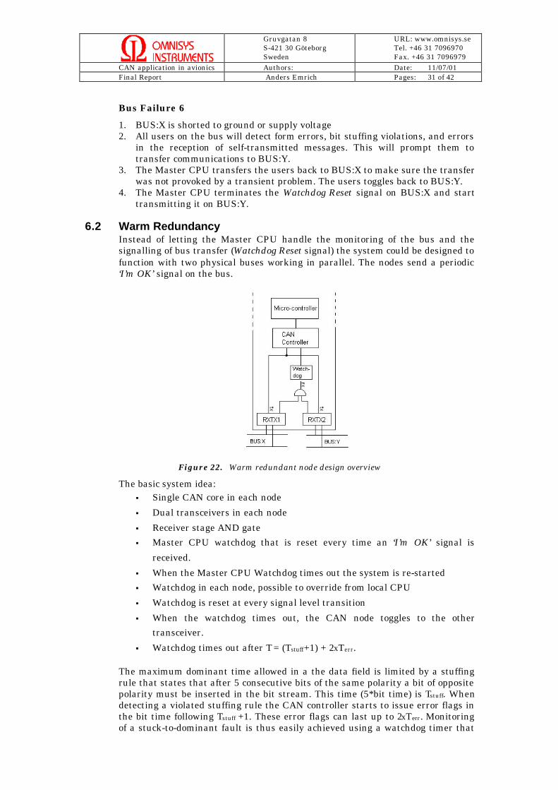
6.2 Warm RedundancyInstead of letting the Master CPU handle the monitoring of the bus and thesignalling of bus transfer (Watchdog Reset signal) the system could be designed tofunction with two physical buses working in parallel. The nodes send a periodic‘I’m OK’ signal on the bus.
Figure 22. Warm redundant node design overview
The basic system idea:§ Single CAN core in each node
§ Dual transceivers in each node
§ Receiver stage AND gate
§ Master CPU watchdog that is reset every time an ‘I’m OK’ signal is
received.
§ When the Master CPU Watchdog times out the system is re-started
§ Watchdog in each node, possible to override from local CPU
§ Watchdog is reset at every signal level transition
§ When the watchdog times out, the CAN node toggles to the other
transceiver.
§ Watchdog times out after T = (Tstuff+1) + 2xTerr.
The maximum dominant time allowed in a the data field is limited by a stuffingrule that states that after 5 consecutive bits of the same polarity a bit of oppositepolarity must be inserted in the bit stream. This time (5*bit time) is Tstuff. Whendetecting a violated stuffing rule the CAN controller starts to issue error flags inthe bit time following Tstuff +1. These error flags can last up to 2xTerr. Monitoringof a stuck-to-dominant fault is thus easily achieved using a watchdog timer that

Gruvgatan 8S-421 30 GöteborgSweden
URL: www.omnisys.seTel. +46 31 7096970Fax. +46 31 7096979
CAN application in avionics Authors: Date: 11/07/01Final Report Anders Emrich Pages: 32 of 42
is set to Tsd = (Tstuff+1) + 2xTerr. (Tsd being the time a stuck-at-dominant failure isdetected)
The system goes through the same start-up sequence as a cold redundant system.
Bus Failure 1
1. BUS:X is broken between CPU:X and PWR:ABC2. The receiver from BUS:X supplies one of the inputs of the AND gate on the
receive stage with an idle signal, i.e. a logic HIGH. This has no affect on thesignal transmitted to the PWR:ABC CAN controller, as the bus signal fromBUS:Y then controls the gate.
Bus Failure 2
1. BUS:X is broken between CPU:X and TC:A2. TC:A continues transmission using BUS:Y. The broken BUS:X supplies one of
the inputs of the AND gate on the receive stage with an idle signal, i.e. a logicHIGH. This has no affect on the signal received by TC:A, as the bus signalfrom BUS:Y then controls the gate.
Bus Failure 3
1. BUS:X is broken between CPU:X and Node:X.2. Node:X continues transmission using BUS:Y. The broken BUS:X supplies one
of the inputs of the AND gate on the receive stage with an idle signal, i.e. alogic HIGH. This has no affect on the signal received by Node:X, as the bussignal from BUS:Y then controls the gate.
Bus Failure 4
1. BUS:X is shorted to ground.2. The transmission of data and commands are continued via BUS:Y.3. The nodes’ receivers see a constant logic LOW, i.e. a dominant bit on the bus,
and after Tsd the Watchdogs time out.4. The input to the receivers’ AND gates is toggled to a logic HIGH, to remove
the influence of the faulty bus on the individual receiver stages, and thesystem is controlled by the contents of BUS:Y.
Bus Failure 5
1. BUS:X is shorted to supply voltage.2. The transmission of data and commands are continued via BUS:Y.3. The receivers see a constant logic HIGH, i.e. a recessive bit on the bus.4. The AND gates on the receiver stages are unaffected by this and the contents
of BUS:Y is coming through to the CAN controllers.
Bus Failure 6
1. The AND gate on CPU:A is damaged.2. CPU:A loses the ‘I’m OK ’ signal from the nodes.3. The Master CPU watchdog times out and the system goes to start-up again

Gruvgatan 8S-421 30 GöteborgSweden
URL: www.omnisys.seTel. +46 31 7096970Fax. +46 31 7096979
CAN application in avionics Authors: Date: 11/07/01Final Report Anders Emrich Pages: 33 of 42
Bus Failure 7
1. The AND gate on Node:X is broken.2. The CAN controller in Node:X takes the Node into off-bus state, the bus is
unaffected.
Bus Failure 8
1. The AND gate in TC:A is damaged.2. The CAN controller in TC:A takes TC:A off-bus.3. TC:B is still functioning and the operation of the bus is unaffected.
Bus failure 9
1. The AND gate in PWR:A is broken.2. The CAN controller in PWR:A takes it off-bus.3. PWR:BC are still functioning and the operation of the bus is unaffected.

Gruvgatan 8S-421 30 GöteborgSweden
URL: www.omnisys.seTel. +46 31 7096970Fax. +46 31 7096979
CAN application in avionics Authors: Date: 11/07/01Final Report Anders Emrich Pages: 34 of 42
7 Medium / High level protocol considerations
7.1 Mapping of ESA telemetry standard on CANThe CCSDS recommendation for packet telemetry, is a technical recommendationfor use in developing packetized telemetry systems. It establishes a commonframework and provides a common basis for the data structures of spacecrafttelemetry stream.
A CAN message has a maximum of 8 bytes of data. To map the CCSDS standardinto these 8 bytes would mean that the actual data transmitted would be severelyreduced, as the majority of the data space would be occupied by CCSDS overhead.This CCSDS overhead contains among other things packet ID, sequence controlflags, and data length. The packet header itself consists of 6 bytes, leaving amaximum of 2 bytes for actual data. Part of this overhead would be pureredundancy if mapped on a CAN message, for example the CAN frame arbitrationfield, serves the same purpose as the application field in the CCSDS packet. Thiscan be argued for other CCSDS packet fields as well. Those not supported in theCAN frame, such as sequence control is easily implemented using predefined bitpatterns in the CAN frame arbitration field.
As a result of the study it was concluded that the design of the CAN protocolallows for transmission of pure CAN messages without the CCSDS packetoverhead.

Gruvgatan 8S-421 30 GöteborgSweden
URL: www.omnisys.seTel. +46 31 7096970Fax. +46 31 7096979
CAN application in avionics Authors: Date: 11/07/01Final Report Anders Emrich Pages: 35 of 42
7.2 CAN protocol suggestion
7.2.1 IdentifiersThe CAN-bus is a multimaster bus with deterministic behaviour with messagepriority based on a message identifier. The use of this identifier controls much ofthe behaviour of a distributed control system based on the CAN-bus. In CAN2.0B, the identifier is 29-bits long and below is a suggestion how to use theseaddress bits. Using the two most significant bits, we divide the messages into fourtypes:
§ Supervisory Mode§ Command Mode - high priority§ Command Mode - standard§ Data transfer
Bit Supervisory Command Command Data28 1 1 0 027 1 0 1 026 Priority Priority Priority data type25 Priority Priority Priority data type24 Priority Priority Priority data type23 Priority Priority Priority record ID22 Priority Priority Priority record ID21 Priority Priority Priority record ID20 Priority Priority Priority record ID19 Priority Priority Priority record ID18 Adress Adress Adress record ID17 Adress Adress Adress record ID16 Adress Adress Adress record ID15 Adress Adress Adress record ID14 Adress Adress Adress record ID13 Adress Adress Adress record ID12 Adress Adress Adress record ID11 Adress Adress Adress record ID10 Command Command Command record ID
9 Command Command Command record ID8 Command Command Command record ID7 Command Command Command record ID6 Command Command Command record ID5 Command Command Command record ID4 Command Command Command record ID3 Command Command Command record ID2 Command Command Command record ID1 Command Command Command record ID0 Command Command Command record ID

Gruvgatan 8S-421 30 GöteborgSweden
URL: www.omnisys.seTel. +46 31 7096970Fax. +46 31 7096979
CAN application in avionics Authors: Date: 11/07/01Final Report Anders Emrich Pages: 36 of 42
7.2.2 Modes
Supervisory mode
The supervisor mode is only used at extraordinary events such as system start-up, subsystem fault debugging, system reconfiguration etc. It could also be usedto override the system from ground via the telecommand/telemetry system.Examples are:
§ forced reboots§ hard interrupts§ setting of hard security levels, max current etc.§ remote code loading§ remote boot with code download§ direct monitoring
Command Mode
High PriorityHigh priority commands involves essential systems and operations, for examplereal-time commands between sensors and actuators on a three-axis stabilizedsatellite.Normal PriorityNormal priority commands involve non-time critical operations, such asdeployment of solar cell arrays, opening/shutting blinds, battery charging.
Data mode
In Data Mode, users get assigned a record ID and a record length. One or morestorage devices record the transmitted data along with the record ID whenordered. When the record is full, the users get a new record ID. The transmit-on-address scheme allows for transparent use of redundant data storage devices.
Storage Record Format: (24-bit identifier + 5-bit data type code) * 8-byterecordsData type code #000 indicates long record and the next 32-bit word gives therecord length N x Bytes data§ Maximum of 16 million records§ Maximum record length: 4 GByte§ Maximum number of minimum records in 512 MByte: 4.5 M records with only
66 % efficiency. 64 Byte records give 94 % efficiency.§ Full data rate on CAN is about 8000 msgs/second: fills up 512 MByte in 1.5 h.
Example with one Storage Device, One Payload Master and severalinstruments.1. Payload Master to Storage Device:
Record On Record ID: #00FF01 and length: #8F (128 x 8-byte)2. Payload Master to Instrument One:
Take 128 samples of 4x16 bits with 10 seconds intervalUse Record ID: #00FF01 and length: #8FStart Now
3. Payload Master to Storage Device:Record On Record ID: #00FF06 and length: #00, #0000FFFF (64 kByte)
4. Payload Master to Instrument Two:Take pictureUse Record ID and length: #00FF06, #00, #0000FFFF (64 kByte)Snap Now

Gruvgatan 8S-421 30 GöteborgSweden
URL: www.omnisys.seTel. +46 31 7096970Fax. +46 31 7096979
CAN application in avionics Authors: Date: 11/07/01Final Report Anders Emrich Pages: 37 of 42

Gruvgatan 8S-421 30 GöteborgSweden
URL: www.omnisys.seTel. +46 31 7096970Fax. +46 31 7096979
CAN application in avionics Authors: Date: 11/07/01Final Report Anders Emrich Pages: 38 of 42
8 System architecture example
8.1 IntroductionTwo Completely independent sets of redundant CAN-buses
§ Essential bus§ Payload Bus
On the essential bus, only three systems are allowed to act in the SupervisoryMode:
§ TC/TM: (Highest Priority)§ (Power Controller)§ System Master
On the Payload Bus, the following systems are allowed to act in the SupervisoryMode:
§ TC/TM: (Highest Priority)§ (Power Controller)§ System Master§ Payload Master
8.2 Basic assumption and preferencesThe basic preferences are:
§ Splitting up Essential System Control (ESC) and PayLoad Control (PLC)§ Use 32-processors with COTS development tools for both ESC and PLC§ Design/use identical units for the both ESC and PLC, combined with 1-2
cold redundant units§ Logical bus for Essential and Payload communication§ Redundant media access devices for both busses§ ESC, PLC and TM/TC system can access both Essential and Payload bus§ Preferrably use electrical star coupling of busses with central, redundant
Hubs
In addition:§ Design/use local DRAM based solid state recorders on ESC and PLC as
Mass Memory§ Use "simple" and reliable microcontrollers for PWR and TM/TC controll
(with direct access to local registers and functions from bus)§ Solve auxillary/off-shelf I/O via "dumb" interface units based on FPGAs§ All subsystems with processor should have an UART interface to
facilitate direct access during development and system integration,together with a PC based graphical interface, e.g. Labview
§ The PWR controller can function as a Lizard brain for the completesystem and supervise the ESC node.
§ The TM/TC node should have the possibility to overide all but the mostessential functions, i.e. PWR
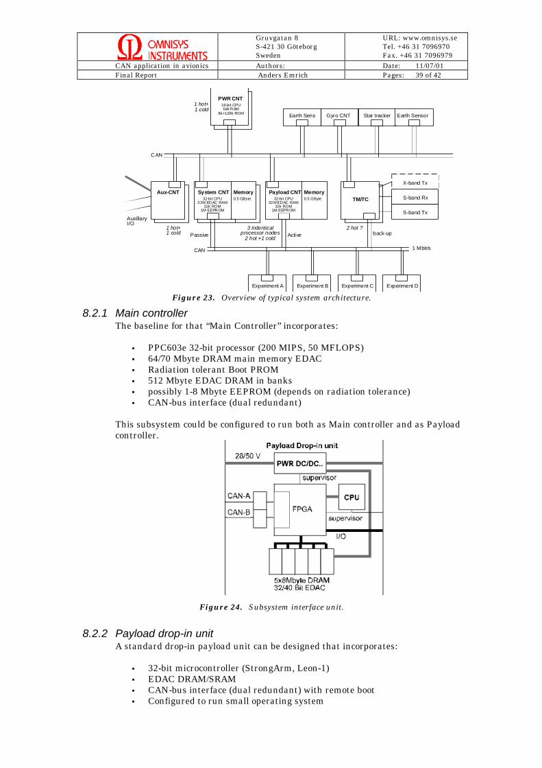
Gruvgatan 8S-421 30 GöteborgSweden
URL: www.omnisys.seTel. +46 31 7096970Fax. +46 31 7096979
CAN application in avionics Authors: Date: 11/07/01Final Report Anders Emrich Pages: 39 of 42
System CNT
PWR CNT
Aux-CNT Payload CNTMemoryTM/TC
Gyro CNT Star tracker Earth Sensor
Experiment A Experiment B Experiment C Experiment D
32-bit CPU32M EDAC RAM
32k ROM1M EEPROM
CAN
16-bit CPU64k RAM
8k+128k ROM
S-band Tx
S-band Rx
X-band Tx
1 Mbit/s
0.5 GByte
Earth Sens
Memory0.5 GByte
CAN
Passive Active back-up
32-bit CPU32M EDAC RAM
32k ROM1M EEPROM
3 indenticalprocessor nodes
2 hot +1 cold
1 hot+1 cold
1 hot+1 cold
2 hot ?
AuxillaryI/O
Figure 23. Overview of typical system architecture.
8.2.1 Main controllerThe baseline for that “Main Controller” incorporates:
§ PPC603e 32-bit processor (200 MIPS, 50 MFLOPS)§ 64/70 Mbyte DRAM main memory EDAC§ Radiation tolerant Boot PROM§ 512 Mbyte EDAC DRAM in banks§ possibly 1-8 Mbyte EEPROM (depends on radiation tolerance)§ CAN-bus interface (dual redundant)
This subsystem could be configured to run both as Main controller and as Payloadcontroller.
Figure 24. Subsystem interface unit.
8.2.2 Payload drop-in unitA standard drop-in payload unit can be designed that incorporates:
§ 32-bit microcontroller (StrongArm, Leon-1)§ EDAC DRAM/SRAM§ CAN-bus interface (dual redundant) with remote boot§ Configured to run small operating system
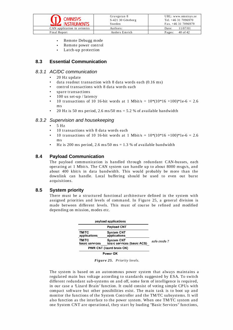
Gruvgatan 8S-421 30 GöteborgSweden
URL: www.omnisys.seTel. +46 31 7096970Fax. +46 31 7096979
CAN application in avionics Authors: Date: 11/07/01Final Report Anders Emrich Pages: 40 of 42
§ Remote Debugg mode§ Remote power control§ Latch-up protection
8.3 Essential Communication
8.3.1 AC/DC communication• 20 Hz update• data readout transaction with 8 data words each (0.16 ms)• control transactions with 8 data words each• spare transactions• 100 us set-up / latency• 10 transactions of 10 16-bit words at 1 Mbit/s = 10*(10*16 +100)*1e-6 = 2.6
ms• 20 Hz is 50 ms period, 2.6 ms/50 ms = 5.2 % of available bandwidth
8.3.2 Supervision and housekeeping• 5 Hz• 10 transactions with 8 data words each• 10 transactions of 10 16-bit words at 1 Mbit/s = 10*(10*16 +100)*1e-6 = 2.6
ms• Hz is 200 ms period, 2.6 ms/50 ms = 1.3 % of available bandwidth
8.4 Payload CommunicationThe payload communication is handled through redundant CAN-busses, eachoperating at 1 Mbit/s. The CAN system can handle up to about 8000 msgs/s, andabout 400 kbit/s in data bandwidth. This would probably be more than thedownlink can handle. Local buffering should be used to even out burstacquisitions.
8.5 System priorityThere must be a structured functional architecture defined in the system withassigned priorities and levels of command. In Figure 25, a general division ismade between different levels. This must of course be refined and modifieddepending on mission, modes etc.
Figure 25. Priority levels.
The system is based on an autonomous power system that always maintains aregulated main bus voltage according to standards suggested by ESA. To switchdifferent redundant sub-systems on and off, some form of intelligence is required,in our case a ‘Lizard Brain’ function. It could consist of voting simple CPUs withcompact software but other possibilities exist. The main task is to boot up andmonitor the functions of the System Controller and the TM/TC subsystems. It willalso function as the interface to the power system. When one TM/TC system andone System CNT are operational, they start by loading "Basic Services" functions,

Gruvgatan 8S-421 30 GöteborgSweden
URL: www.omnisys.seTel. +46 31 7096970Fax. +46 31 7096979
CAN application in avionics Authors: Date: 11/07/01Final Report Anders Emrich Pages: 41 of 42
such as direct "terminal mode" from ground for the TM/TC system and applyingbasic attitude control for the System CNT. This could be defined as a safe modetype of operation. These services should be implented as high priorityprocesses/drivers. When all lower levels functions correctly, System applicationscan operate. These provide more intelligent control, data handling, on-boarddecision making etc. On top of the System applications, payload control payloadapplications run.
8.6 Start-up
1) Power system (OK)2) Lizard Brain (16-bit CPU, Triple majority voting CPU or triple majority
voting watchdog with cold redundant CPU)3) Lizard Brain controls Main controller (Polling boot; Main, Payload,
Redundant)(3.b starting telemetry safe mode, ACDC safe mode)
4) Main controller monitors and controls essential subsystems5) Essential subsystems, ACDC, thrusters, ….6) Main controller starts (controls) payload controller7) Payload controller controls payload8) Payload
Boot procedure:
1) Power bus voltage established (all subsystems off)2) Lizard brain failsafe boot (Tripple majority voting CPU or Tripple majority
voting watchdog with cold redundant CPU)3) Lizard brain boots (power on) on Main controller [Main, Payload, Redundant]4) Power on: wait 1 sec, if no answere on 1553, go to next Controller5) If all three fail, start Telemetry system in failsafe mode as 1553 Bus
controller6) Main controller starts essential subsystems7) Possible polling start of redundant subsystems8) Main controller starts Payload controller9) Main controller enables Payload instruments

Gruvgatan 8S-421 30 GöteborgSweden
URL: www.omnisys.seTel. +46 31 7096970Fax. +46 31 7096979
CAN application in avionics Authors: Date: 11/07/01Final Report Anders Emrich Pages: 42 of 42
9 References
Ref 1 ISO 11898:1993, Road vehicles – Interchange of digital information –Controller area network (CAN) for high-speed communication, Nov 1993
Ref 2 Statement of Work, ESTEC, April 1999
Ref 3 Packet Telemetry, CCSDS 102.0-B-4 Blue Book, Nov 1995
CAN for space ftp://ftp.estec.esa.nl/pub/ws/wsd/CAN/canspace.htmCAN HUG http://www.canhug.org/CAN Kingdom http://www.kvaser.org/CiA http://www.can-cia.de/ODVA http://www.odva.org/SDS http://content.honeywell.com/sensing/prodinfo/sds/
Smart Distributed System (Honeywell).Bosch http://www.bosch.de/de_e/productworld/k/
products/prod/can/BoschIPE CAN http://141.44.61.248/NT/CAN/Welcome.html
IPE CAN Home Page, University of Magdeburg.Ken Tindell http://www.docs.uu.se/~ken/Philips http://www-us.semiconductors.philips.com/can/ Siemens Institute http://www.mfuniversity.com/siemens/homepage.htmStaffan's CAN page http://www.algonet.se/~staffann/developer/CAN.htm
CAN controllers http://www.can-cia.de/pc.htmCAN tranceivers http://www.can-cia.de/pth.htm
10 List of books and links
Wolfhard LawrenzCAN System Engineering : From Theory to Practical ApplicationsSpringer, 1997ISBN 0-387-94939-9
Wolfhard Lawrenz (Hrsg.)CAN Controller Area Network - Grundlagen und PraxisHüthig, 1999ISBN 3-7785-2734-7
Konrad Etschberger (Hrsg.)CAN Controller Area Network - Grundlagen, Protokolle, Bausteine,Hanser, 2000ISBN 3-446-19431-2
Dominique ParetLe Bus CANDUNOD, 1997ISBN 2-10-003164-3
More books underhttp://www.bosch.de/de_e/productworld/k/products/prod/can/content/Literature.html