Embed Size (px)
Citation preview

CAN 2.0A/B ↔ RS232/RS485 Converter (Prod. No. #632)
- Listen Only Mode –
No influence of the CAN system by the converter
or
- Normal Mode –
A/B 11, 29 Bit ID
CAN-side: 10 kbps ... 1 Mbps
RS232- side: up to 1 Mbps
RS485- side: up to 3 Mbps

Table of Contents
Table of Contents.....................................................................................................................................2
1 Introduction...........................................................................................................................................3
2 Startup...................................................................................................................................................4
3 Converter Block Diagram.......................................................................................................................5
4 Setup Mode............................................................................................................................................5
5 Normal Mode.........................................................................................................................................7
6 Converter ASCII Commands...................................................................................................................9
7 Technical Specifications: CAN ↔ RS232/RS485 Adapter (#630)........................................................12

1 Introduction
As a powerful tool the CAN converter supports development, service, testing and maintenance of
CAN-based systems. They are suitable for online monitoring and manipulation of the bus as well as
their logging.
The converter supports 11 and 29 bit identifiers (CAN2.0A/2.0B). The Listen Only mode it is no
transmission of Ack bit and error frames, thereby influencing the CAN system is avoided.
The CAN baud rate is detected automatically by the converter. As well the converter provides the
ability to adjustthe baud rate and other parameters to your needs.
The CAN Converter is ideally suitable for the investigation of the CAN bus data. The converter can be
easily plugged into any RS232 or RS485 port of a computer or notebook. The data can be displayed
in any standard terminal program or the 4N-CAN-terminal program.
More information can be found in the following sections.
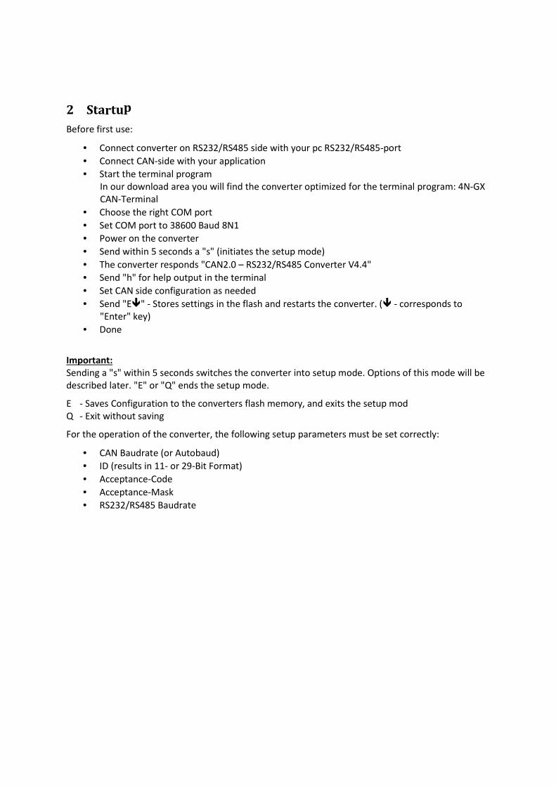
2 Startup
Before first use:
• Connect converter on RS232/RS485 side with your pc RS232/RS485-port
• Connect CAN-side with your application
• Start the terminal program
In our download area you will find the converter optimized for the terminal program: 4N-GX
CAN-Terminal
• Choose the right COM port
• Set COM port to 38600 Baud 8N1
• Power on the converter
• Send within 5 seconds a "s" (initiates the setup mode)
• The converter responds "CAN2.0 – RS232/RS485 Converter V4.4"
• Send "h" for help output in the terminal
• Set CAN side configuration as needed
• Send "E�" - Stores settings in the flash and restarts the converter. (� - corresponds to
"Enter" key)
• Done
Important:
Sending a "s" within 5 seconds switches the converter into setup mode. Options of this mode will be
described later. "E" or "Q" ends the setup mode.
E - Saves Configuration to the converters flash memory, and exits the setup mod
Q - Exit without saving
For the operation of the converter, the following setup parameters must be set correctly:
• CAN Baudrate (or Autobaud)
• ID (results in 11- or 29-Bit Format)
• Acceptance-Code
• Acceptance-Mask
• RS232/RS485 Baudrate


4.1 CAN ID Filter Setup
The converters accept messages from specific IDs which can be defined by the CAN identifier (CI), the
CAN-Acceptance-Code (CAC) and the CAN-Acceptance-Mask (CAM). CAC defines the mandatory
required bits of the received ID and the CAM, the bits to ignore. The CAN identifier
can be determined by the choice of converter id to whether either will be accepted ONLY 11
bits (id <= 7FF) or ONLY29 bit addresses (id <= 7FF).
Sample:
CAC: 3A0 011 1010 0000
CAM: 0E 1110
---------------------------------------
Filter: 011 1010 xxx0 x: not relevant
Accepted IDs: 011 1010 0000 3A0
011 1010 0010 3A2
011 1010 0100 3A4
011 1010 0110 3A6
011 1010 1000 3A8
011 1010 1010 3AA
011 1010 1100 3AC
011 1010 1110 3AF
In this example, the bits 2 to 4 are not relevant. All other bits must match.
Mathematical condition: (ID OR AC) = (CAC OR AC)
Only if the two results are equal, the ID is accepted and output to the USB port for further
processing.
Basically it works like this:
CAN-Acceptance Filter B011 1010 0000
CAN-Acceptance Mask B000 0000 1110
The filter would pass only 3A0, but only Bits 1-3 are flagged, so 3A0,3A2,3A4,3A6,3A8,3AA,3AC and
3AE will be passed. In logical terms: (Message Bit AND Filter Bit) or Mask Bit
More samples:
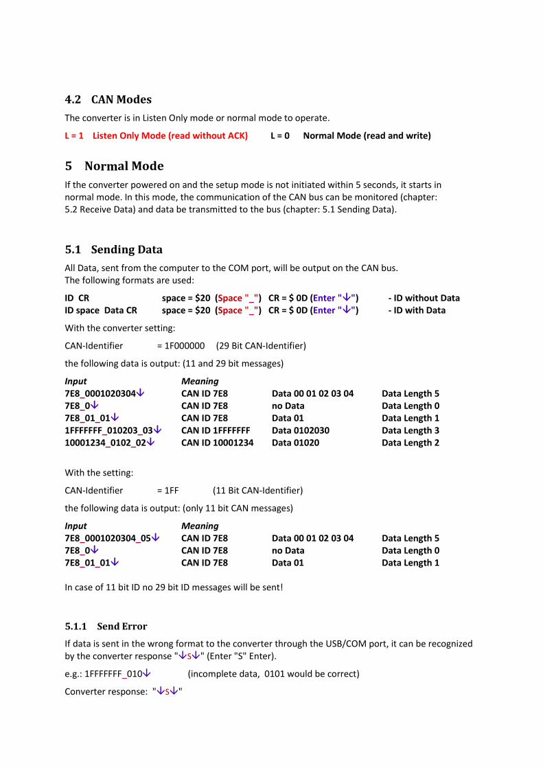
4.2 CAN Modes
The converter is in Listen Only mode or normal mode to operate.
L = 1 Listen Only Mode (read without ACK) L = 0 Normal Mode (read and write)
5 Normal Mode
If the converter powered on and the setup mode is not initiated within 5 seconds, it starts in
normal mode. In this mode, the communication of the CAN bus can be monitored (chapter:
5.2 Receive Data) and data be transmitted to the bus (chapter: 5.1 Sending Data).
5.1 Sending Data
All Data, sent from the computer to the COM port, will be output on the CAN bus.
The following formats are used:
ID CR space = $20 (Space "_") CR = $ 0D (Enter "�") - ID without Data
ID space Data CR space = $20 (Space "_") CR = $ 0D (Enter "�") - ID with Data
With the converter setting:
CAN-Identifier = 1F000000 (29 Bit CAN-Identifier)
the following data is output: (11 and 29 bit messages)
Input Meaning
7E8_0001020304� CAN ID 7E8 Data 00 01 02 03 04 Data Length 5
7E8_0� CAN ID 7E8 no Data Data Length 0
7E8_01_01� CAN ID 7E8 Data 01 Data Length 1
1FFFFFFF_010203_03� CAN ID 1FFFFFFF Data 0102030 Data Length 3
10001234_0102_02� CAN ID 10001234 Data 01020 Data Length 2
With the setting:
CAN-Identifier = 1FF (11 Bit CAN-Identifier)
the following data is output: (only 11 bit CAN messages)
Input Meaning
7E8_0001020304_05� CAN ID 7E8 Data 00 01 02 03 04 Data Length 5
7E8_0� CAN ID 7E8 no Data Data Length 0
7E8_01_01� CAN ID 7E8 Data 01 Data Length 1
In case of 11 bit ID no 29 bit ID messages will be sent!
5.1.1 Send Error
If data is sent in the wrong format to the converter through the USB/COM port, it can be recognized
by the converter response "�S�" (Enter "S" Enter).
e.g.: 1FFFFFFF_010� (incomplete data, 0101 would be correct)
Converter response: "�S�"

5.2 Receiving Data
What data received by the converter and at RS232/RS485 side are output for further processing
depends on the configuration of the CAN identifier, the CAM-Acceptance-Code and the CAN-
Acceptance-Mask. A detailed description of these parameters can be found with examples in
chapter "3.1 CAN ID Filter Setup".
Accepted CAN messages will be output in ASCII format as followed:
ID space Data space Length CR space = $20 (Space "_") CR = $ 0D (Enter "�")
With the converter setting:
CAN-Identifier = 1F000000 (29 Bit CAN-Identifier)
CAN-Acceptance-Code = 00000000 (0 receives all CAN-Frames)
CAN-Acceptance-Mask = FFFFFFFF (F receives all CAN-Frames)
the following data is output on the USB side: (11 and 29 bit message)
PC Output Meaning
7E8_0001020304_05� CAN ID 7E8 Data 00 01 02 03 04 Data Length 5
7E8_0� CAN ID 7E8 no Data Data Length 0
7E8_01_01� CAN ID 7E8 Data 01 Data Length 1
1FFFFFFF_010203_03� CAN ID 1FFFFFFF Data 0102030 Data Length 3
10001234_0102_02� CAN ID 10001234 Data 01020 Data Length 2
With the setting:
CAN-Identifier = 1FF (11 Bit CAN-Identifier)
CAN-Acceptance-Code = 00000000 (0 receives all CAN-Frames)
CAN-Acceptance-Mask = FFFFFFFF (F receives all CAN-Frames)
the following data is output: (only 11 bit CAN messages)
PC Output Meaning
7E8_0001020304_05� CAN ID 7E8 Data 00 01 02 03 04 Data Length 5
7E8_0� CAN ID 7E8 no Data Data Length 0
7E8_01_01� CAN ID 7E8 Data 01 Data Length 1
5.2.1 Receive Error
Error LED (Buffer Overflow LED) lights up, if data is sent to fast from the PC to the converter.
Buffer Overflow can be recognized by "�E�" (Enter "E" Enter).
"�E�" is send from converter to PC.
At full CAN bus utilization can rarely cause errors (at 1 Mbps 100% bus utilization).
To recognize this is the fact that the messages are not received in full.
z.B.
7E8_000102� CAN ID 7E8 Data 00 01 02 ? Data Length?
7E8_01� CAN ID 7E8 Data 01 ? Data Length?

6 Converter ASCII Commands
(CR)=Enter (Dez=13, Hex=0D)
Es können Klein- und Großbuchstaben verwendet werden.
Befehl Funktion
S S Setup-Mode activation
Is possible only after power up in the first 5 seconds! In setup mode,
settings for the CAN side can be made and stored.
P P0(CR)
P1(CR)
Shows settings stored in converter RAM – changes have to be saved
by "E" xit
Show default settings.
Response: “Settings: List(CR)OK(CR)“ or “ERROR(CR)“
e.g.
C CAN-Bitrate : 5
L CAN-Mode : 0
I CAN-Identifier : 10000000
A CAN-Acceptance-Code : 00000100
M CAN-Acceptance-Mask : 00000000
R Baudrate : 3
Identifier Length : 29
Acc. Code Length : 32
Acc. Mask Length : 32
OK
C C0(CR)
C1(CR)
C2(CR)
C3(CR)
C4(CR)
C5(CR)
C6(CR)
C7(CR)
C8(CR)
C9(CR)
CA(CR)
CB(CR)
CC(CR)
CD(CR)
CE(CR)
CF(CR)
10 kbps CAN Bitrate
20 kbps CAN Bitrate
25 kbps CAN Bitrate
50 kbps CAN Bitrate
62,5 kb CAN Bitrate
100 kbps CAN Bitrate
125 kbps CAN Bitrate
128,2 kb CAN Bitrate
192 kbps CAN Bitrate
250 kbps CAN Bitrate
500 kbps CAN Bitrate
800 kbps CAN Bitrate
1.0 Mbps CAN Bitrate Other baud rates available on request
Autobaud – automatic baudrate Detection
Autobaud – automatic baudrate Detection
Autobaud – automatic baudrate Detection
Response: “Settings: List(CR)OK(CR)“ or “ERROR(CR)“

Befehl Funktion
I Ixxx(CR)
or
Ixxxxxxxx(CR)
Identifier in Hex (000...7FF) 11 Bit Standard Format
or
Identifier in Hex (00000000...1FFFFFFF) 29 Bit Extended Format
This setting determines whether only 11-bit or 11-bit and 29-bit are
accepted by CAN-Acceptance-Code and CAN-Acceptance-Mask.
Response: “List of parameters: (CR)OK(CR)” or “ERROR(CR)“
L Lx(CR) Listen Mode Only (0...1)
0 – CAN Normal Mode (read and write)
1 – CAN Listen Only Mode (listening only, read)
Response: “List of parameters: (CR)OK(CR)” or “ERROR(CR)“
A Axxxxxxxx(CR) CAN-Acceptance-Code x = (0...000007FF) 11 Bit Standard Format
CAN-Acceptance-Code x = (0...1FFFFFFF) 29 Bit Extended Format
x = 0 receives all CAN-Frames
Response: “List of parameters: (CR)OK(CR)” or “ERROR(CR)“
M Mxxxxxxxx(CR) CAN-Acceptance-Mask x = (0..000007FF) 11 Bit Standard Format
CAN-Acceptance-Mask x = (0..1FFFFFFF) 29 Bit Extended Format
x = F receives all CAN-Frames
Response: “List of parameters: (CR)OK(CR)” or “ERROR(CR)“
R R0(CR)
R1(CR)
R2(CR)
R3(CR)
R4(CR)
R5(CR)
R6(CR)
R7(CR)
R8(CR)
R9(CR)
RA(CR)
RB(CR)
RC(CR)
RD(CR)
RE(CR)
RF(CR)
600 bps RS232/RS485 Baudrate (all 8 N 1)
1200 bps
2400 bps
4800 bps
9600 bps
19200 bps
38400 bps
57600 bps
115200 bps
230000 bps
500000 bps
600000 bps
750000 bps
1000000 bps
1500000 bps
3000000 bps Other baud rates available on request
Response: “ (CR)OK(CR)” or “ERROR(CR)”
V Software Version Number
Response: „Software Version: x.x(CR)“ x = 0..F
N Converter Nummer
Response: „Converter-ID: xxxx xxxx(CR)“ x= 0..F

Befehl Funktion
?
or
H
?
or
H
Help
This table is output to the COM port
E E Exit
Exits the Setup Mode and saves the configuration in flash memory of the
converter, followed by a Reset = Power On(Restart)
Response: e.g.
C CAN-Bitrate : 5
L CAN-Data Length : 8
I CAN-Identifier : 1F0000000
A CAN-Acceptance-Code : 00000100
M CAN-Acceptance-Mask : 00000000
R USB-Baudrate : 3
Identifier Length : 29
Acc. Code Length : 32
Acc. Mask Length : 32
SAVE to EEprom
OK
RESET
Q Q Quit
Exits the setup mode WITHOUT saving changes in the in flash memory of
the converter, followed by a Reset = Power On(Restart)
Response:
OK
RESET
Other parameters, functions are available on request.
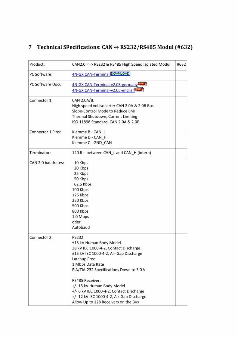
7 Technical Specifications: CAN ↔ RS232/RS485 Modul (#632)
Product: CAN2.0 <=> RS232 & RS485 High Speed Isolated Modul #632
PC Software: 4N-GX CAN-Terminal
PC Software Docu: 4N-GX CAN-Terminal-v2.05-germany
4N-GX CAN-Terminal-v2.05-english
Connector 1: CAN 2.0A/B:
High speed vollisolierter CAN 2.0A & 2.0B Bus
Slope-Control Mode to Reduce EMI
Thermal Shutdown, Current Limiting
ISO 11898 Standard, CAN 2.0A & 2.0B
Connector 1 Pins: Klemme B - CAN_L
Klemme D - CAN_H
Klemme C - GND_CAN
Terminator: 120 R - between CAN_L and CAN_H (intern)
CAN 2.0 baudrates: 10 Kbps
20 Kbps
25 Kbps
50 Kbps
62,5 Kbps
100 Kbps
125 Kbps
250 Kbps
500 Kbps
800 Kbps
1.0 Mbps
oder
Autobaud
Connector 2: RS232:
±15 kV Human Body Model
±8 kV IEC 1000-4-2, Contact Discharge
±15 kV IEC 1000-4-2, Air-Gap Discharge
Latchup Free
1 Mbps Data Rate
EIA/TIA-232 Specifications Down to 3.0 V
RS485 Receiver:
+/- 15 kV Human Body Model
+/- 6 kV IEC 1000-4-2, Contact Discharge
+/- 12 kV IEC 1000-4-2, Air-Gap Discharge
Allow Up to 128 Receivers on the Bus

True-Fail-Safe Receiver
-7V .. +12V Common-Mode Range
Thermal Protection Against Output Short Circuit
RS485 Driver:
+/- 9 kV Human Body Model
Slev-Rate Limited for Errorless Data Transmission
-7V .. +12V Common-Mode Range
Current Limiting
Thermal Shutdown for Driver-Overload Protection
Connectron 2 Pins: RS232:
Klemme M - RXD In
Klemme K - TXD Out
Klemme A - GND_RS
RS485:
Klemme J - TX+ Out
Klemme L - TX- Out
Klemme H - RX+ In
Klemme G - RX- In
Klemme A - GND_RS
Connector 3: Power In
Connector 3 Pins: Power In:
Klemme E - 9..36V DC oder AC Input
Klemme F - 9..36V DC oder AC Input
RS232 & RS485
baudrates:
600 bps (all 8 N 1)
1200 bps
2400 bps
4800 bps
9600 bps
19200 bps
38400 bps
57600 bps
115200 bps
230000 bps
500000 bps
600000 bps
750000 bps
1000000 bps
1500000 bps
3000000 bps
RS232 up to 1 Mbps, RS485 up to 3 Mbps
Galvanic isolation: High common-mode transient immunity: >25 kV/µs
Safety and regulatory approvals

UL recognition: 5000 V rms for 1 minute per UL 1577
CSA Component Acceptance Notice #5A
IEC 60950-1: 600 V rms (reinforced)
IEC 60601-1: 250 V rms (reinforced)
VDE certificate of conformity
DIN V VDE V 0884-10 (VDE V 0884-10):2006-12
VIORM = 846 V peak
Indicators: Run LED
CAN LED
RS232/RS485 LED
Buffer Overflow LED
Poerating tmperatur: -5..+70°C
Dimensions (mm) 90 x H 75 x B 23 for Rail Din