Embed Size (px)
Citation preview

CAMSO DTS 129 Dirt-to-snow bike conversion system DTS 129: 1099-01-1840
USER MANUAL 2018
CAMSO DTS 129 Dirt-to-snow bike conversion system DTS 129: 1099-01-1840
USER MANUAL 2018

Formerly Camoplast Solideal, Camso is the best of Camoplast and Solideal. To keep moving forward while staying true to our
history, we're now Camso, the Road Free Company.
Camso inc.4162, rue Burrill - Local A
Shawinigan, QC G9N 0C3CANADA
TECHNICAL SUPPORTIf your dealer or distributor is unable to solve a problem related with the System, you may contact the Camso support team from Monday to Friday.
E-Mail: [email protected]: www.camso.co
System Serial Number: 9025ICE _______________
Original noticeTranslations in other languages available at www.camso.co
� WARNINGPlease read carefully each part of this document as well as model specific InstallationGuidelines prior to assembling, installing and using the Conversion System.
® and MC are trademarks of Camso inc.All rights reserved. ©2017 Camso inc.
Printed in Canada.
TABLE OF CONTENTS
INTRODUCTION . . . . . . . . . . . . . . . . . . . . . . . . . . . . . . . . . . . . . . . . . . . . . . . . . . . . . . . . . . . . . . . . . . . . . . . . . . . . . . . 1
SYMBOLS AND SIGNAL WORDS . . . . . . . . . . . . . . . . . . . . . . . . . . . . . . . . . . . . . . . . . . . . . . . . . . . 1
GENERAL INFORMATION . . . . . . . . . . . . . . . . . . . . . . . . . . . . . . . . . . . . . . . . . . . . . . . . . . . . . . . . . . 1
SERIAL NUMBER LOCATION . . . . . . . . . . . . . . . . . . . . . . . . . . . . . . . . . . . . . . . . . . . . . . . . . . . . . . . 1
SAFETY . . . . . . . . . . . . . . . . . . . . . . . . . . . . . . . . . . . . . . . . . . . . . . . . . . . . . . . . . . . . . . . . . . . . . . . . . . . . . . . . . . . . . 2
OPERATING INSTRUCTIONS . . . . . . . . . . . . . . . . . . . . . . . . . . . . . . . . . . . . . . . . . . . . . . . . . . . . . . . . . . . . . . . . . . . . 4
TORQUE SPECIFICATIONS . . . . . . . . . . . . . . . . . . . . . . . . . . . . . . . . . . . . . . . . . . . . . . . . . . . . . . . . . . . . . . . . . . . . . 5
ACCESSORIES . . . . . . . . . . . . . . . . . . . . . . . . . . . . . . . . . . . . . . . . . . . . . . . . . . . . . . . . . . . . . . . . . . . . . . . . . . . . . . . 5
ADJUSTMENTS . . . . . . . . . . . . . . . . . . . . . . . . . . . . . . . . . . . . . . . . . . . . . . . . . . . . . . . . . . . . . . . . . . . . . . . . . . . . . . . 6
ANGLE OF ATTACK - SUSPENSION . . . . . . . . . . . . . . . . . . . . . . . . . . . . . . . . . . . . . . . . . . . . . . . . . 6
DRIVE CHAIN TENSION . . . . . . . . . . . . . . . . . . . . . . . . . . . . . . . . . . . . . . . . . . . . . . . . . . . . . . . . . . . 7
SUSPENSION ADJUSTMENT . . . . . . . . . . . . . . . . . . . . . . . . . . . . . . . . . . . . . . . . . . . . . . . . . . . . . . . 8
SUSPENSION - LIMITER CABLE ADJUSTMENT . . . . . . . . . . . . . . . . . . . . . . . . . . . . . . . . . . . . . . 10
RUBBER TRACK TENSION . . . . . . . . . . . . . . . . . . . . . . . . . . . . . . . . . . . . . . . . . . . . . . . . . . . . . . . 11
MAINTENANCE . . . . . . . . . . . . . . . . . . . . . . . . . . . . . . . . . . . . . . . . . . . . . . . . . . . . . . . . . . . . . . . . . . . . . . . . . . . . . . 12
LUBRICATION . . . . . . . . . . . . . . . . . . . . . . . . . . . . . . . . . . . . . . . . . . . . . . . . . . . . . . . . . . . . . . . . . . 15
WEAR . . . . . . . . . . . . . . . . . . . . . . . . . . . . . . . . . . . . . . . . . . . . . . . . . . . . . . . . . . . . . . . . . . . . . . . . . 17
2-YEAR LIMITED WARRANTY . . . . . . . . . . . . . . . . . . . . . . . . . . . . . . . . . . . . . . . . . . . . . . . . . . . . . . . . . . . . . . . . . . 21
TROUBLESHOOTING . . . . . . . . . . . . . . . . . . . . . . . . . . . . . . . . . . . . . . . . . . . . . . . . . . . . . . . . . . . . . . . . . . . . . . . . . 22
PARTS LIST . . . . . . . . . . . . . . . . . . . . . . . . . . . . . . . . . . . . . . . . . . . . . . . . . . . . . . . . . . . . . . . . . . . . . . . . . . . . . . . . . 24
1099-01-1840- VERSION B
INTRODUCTION
INTRODUCTION
Thank you for choosing the Camso DTS 129 Dirt-To-Snow bike conversion system, (hereinafterreferred to as the "System"). This conversionsystem for off-road motorcycle is designed forexceptional traction and floatation performancethat will take you off the beaten path and push theboundaries back with each turn of the handle. Wewent the extra mile to offer you a quality, high-performance conversion system that is suited tothe handling behavior of your off-road motorcycleand that will take you to places only dreamt ofwhile summer riding.
SYMBOLS AND SIGNAL WORDS
This guide uses the following signal words andsymbols to emphasize particular information:
CAUTION: Indicates a potentially hazardoussituation which, if not avoided, may result indamage to the motorcycle and Conversion Systemcomponents.
NOTE: Indicates supplementary information.
The Prohibition Safety Sign indicates anaction NOT to be taken in order to avoid ahazard.
The Mandatory Action Sign indicates anaction that NEEDS to be taken to avoid ahazard.
GENERAL INFORMATION
• All figures, information or photos presented inthis document are up to date at the time ofpublication. However, they may change withoutnotice.
• Read and follow the indications contained in theDTS User Manual and Installation Guidelinescarefully. Their contents remains applicable afterinstallation of the System.
• This document should be read by every personwho operates a motorcycle equipped with theSystem.
• This document is an integral part of the System.Pass it along to any new System owner.
• Consult legal authorities where you drive yourmotorcycle equipped with the System beforeusage to ensure that you respect all applicablelaws and regulations.
• Motorcycle Conversion Systems are designed toreduce ground pressure and increase vehicletraction. However, during normal operatingconditions, vehicle speed should be reducedcompared to a wheeled vehicle.
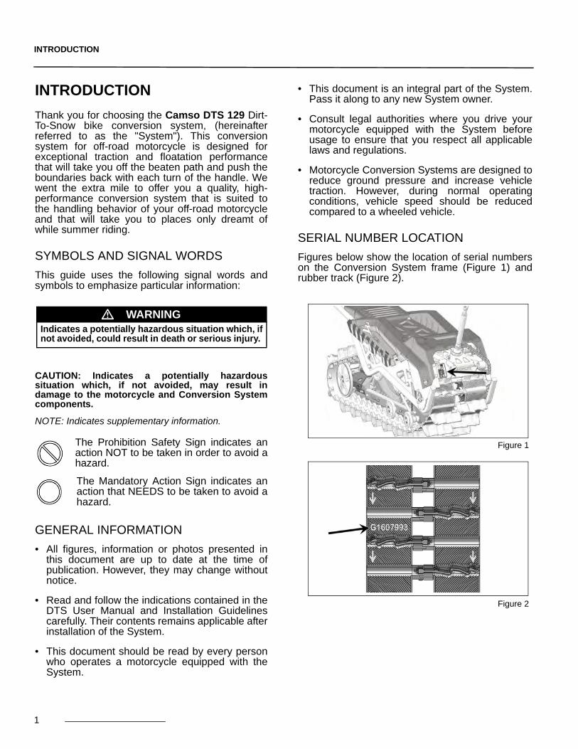
SERIAL NUMBER LOCATION
Figures below show the location of serial numberson the Conversion System frame (Figure 1) andrubber track (Figure 2).
Figure 1
Figure 2
� WARNINGIndicates a potentially hazardous situation which, ifnot avoided, could result in death or serious injury.
1

SAFETY
2
SAFETY
WARNING STICKERS
You will find affixed on the Conversion System’sframe the warning stickers shown in the illustrationbelow. Read the stickers carefully and understandthem before using the Conversion System. Theycontain important information about safety andproper operation of the Conversion System.
CAUTION: Do not remove the warning stickers fromthe frame. If a sticker is damaged, have it replacedby an authorized Camso dealer.
WARNING - STRUT ROD
Assembly configurations - TheStrut Rod can be assembled to theDTS rear track system under twopossible configurations. Refer tothe Installation Guidelines specificto your motorcycle to identify theright assembly configuration.
GENERAL WARNING
User Manual - Users must read theUser Manual before attempting tooperate a vehicle equipped with aConversion System.
If Conversion System is sold or inany way transferred to a new user,the User Manual must also betransferred to the new user.
Moving Parts - Hands or fingerscaught between moving parts of theequipment present a danger to lifeor limb. Turn motor off beforeservicing Conversion System.
Maintenance Schedule - Followthe instructions contained in theMaintenance Schedule section ofthe User Manual to ensure safe andlong–lasting operation of theConversion System.
TENSIONER WARNING
Tensioner Bolt Warning - If track tensionadjustment is required, the tensioner assembly boltmust be loosened first. Re-tighten the bolt to therecommended torque specification (35 N-m) aftercompleting the tension adjustment.

SAFETY
USER NOTICE AND DISCLAIMERThe Camso DTS 129 Dirt-To-Snow bikeconversion System is designed to provideexceptional traction and floatation in all winterconditions. This document holds important informationregarding driving a motorcycle equipped with theCamso DTS 129 System by Camso. It ismandatory that every user takes the time tocarefully read, understand and then consult thisreference manual and user guide as well as themotorcycle owner's manual as needed. Whenpurchasing either a new or used ConversionSystem, the user must obtain all documentationrelated to the System, including manuals andguides related to the motorcycle on which theSystem is installed.If need be, contact the Camsoproducts dealer nearest to you to obtain anyadditional information. You may also consult theCamso Web site at www.camso.co and contactour technical support by email [email protected] believes that there are certain risks relatedto the installation and use of the System. Ourexperience shows that the System is safe.However, the user must be aware of the risksrelated with driving a motorcycle with theparticularities of this type of System. Themotorcycle rider must, at all times, respect allapplicable laws and regulations, the indications ofthe System manufacturer and the indications fromthe motorcycle manufacturer fixed by law, namelywhen age restrictions exist and motorcycle baseequipment is required (headlights, flashers andbrake lights, rear view mirror, etc.). The user mustalways wear adequate safety equipment, such asa helmet, safety glasses (or visor), protectiveclothing, boots and gloves. It is understood thatdriving while impaired or intoxicated presents adanger for the motorcycle user and others and isagainst the law.The System consists of many moving parts,including transmission wheels. If an object lodgesitself or becomes jammed into the System andblocks the track, it is mandatory to stop the engineand the vehicle and apply the security brakebefore removing said object. By avoiding to do so,the user exposes himself to sudden movement ofthe motorcycle or to breakage of a part orcomponent coming from the System, which couldcause severe injuries. It is also very important towear full length clothing and always avoid hangingor stringy accessories. Driving a motorcycle equipped with such a Systemrequires particular precautions and a knowledge ofproper driving techniques of such vehicles.
An evaluation by the user of the conditions andterrain (state of the ground, grade of hill, density ofsnow, etc.) is equally essential.A motorcycle equipped with a System cannotcompete and/or be used to perform stunts,acrobatics or other exploits, as these could result inloss of control or severe injuries.Insufficient knowledge of a motorcycle during downhill riding, climbs and crossing of obstacles andturns can result in tipping or roll over, and cancause severe injuries. Carrying a passenger, a load or attaching a tow cancause the motorcycle to be less stable, andaffectability. Unless otherwise prescribed by lawand by the motorcycle manufacturer, you must notcarry a passenger, loads or tow any objects.The installation of a System:• Increases ground clearance.• Changes the center of gravity.• Increases the motorcycle width and weight.• Reduces ground pressure.These parameters will effectively change drivingcharacteristics of a motorcycle equipped with theSystem. Consequently, it is highly recommended that theuser adapt his driving style to the newcharacteristics mentioned above. The rider mustalways use caution when he crosses obstacles,circulates through narrow paths, meets vehiclescoming in the opposing direction, etc.As it was designed, the System will considerablyreduce the motorcycle top speed and can falsifythe speedometer. Generally, the Systemtransmission wheel diameter is less than that of thetire. Therefore, the vehicle speed will be less thanthat actually displayed. Whether the motorcycle isequipped or not with the System, users mustalways adapt the speed to actual drivingconditions. Users must never exceed speed limitsor drive faster than their capacities allow.Excessive speed remains one of the main causesof severe motorcycle accidents.Camso is proud to offer dirt-to-snow motorcycleconversion kits within its wide range of products.Motorcycle Conversion Systems are not onlyreliable, but safe. However, there are risks inherentto riding a motorcycle equipped with the System. Itis therefore very important that the riderfamiliarizes himself with proper driving techniquesof a motorcycle equipped with a System, and thathe adapts his driving to his level of experience andcontinually evaluates operating conditions andterrain to safely and efficiently make the best of theCamso motorcycle Conversion System.
3

OPERATING INSTRUCTIONS
4
OPERATING INSTRUCTIONS
HINTS AND TIPS
• Before leaving for an excursion, make sure tobring with you the following: 13 mm, 15 mm, 16mm, wrenches and sockets, 3 and 6 mm Allenkeys, an axe, a shovel, a tow cable, a containerof fuel, a screwdriver type pry bar and anadjustable wrench.
• Generally, the slower you go, the better thetraction will be.
• On excursions on unknown or remote terrain,make sure to have with you a cellular or satellitephone, a first aid kit and spare parts.
• When riding off trails, always be cautious ofpotential hidden obstacles.
• In deep snow, do not intentionally spin the track(track keeps on turning while motorcycle doesnot move). This could cause the vehicle to getstuck.
BREAK-IN PERIOD
CAUTION: A break-in period is necessary to allowthe components of the system to settle and adjustthemselves to each other.
During the break-in period (8 hours or 160 kilometers), follow these recommendations:
• During break-in, avoid operating in dry and cleanconditions such as icy trails, gravel, asphalt orsand.
• A GOOD break-in period must be done in alubricated environment such as a groomed trailor soft snow.
• A BAD break-in period can generate smoke,odors of burned rubber or plastic as well asplastic deposits on track clips.
CAUTION: Non-compliance with the usagerecommendations can lead to a warranty claimrefusal.
CAUTION: The rider is responsible for following therecommended scheduled maintenance described inthis manual.
CAUTION: Reduce your speed at all times; aConversion System installed on a motorcycle doesnot have the same absorption capacity as a tire.
PRE-USE VERIFICATION
CAUTION: Before each ride make sure that theSystem’s wheels and moving parts are free and thatthey are not frozen or stuck on the frame.
CAUTION: Verify that the motorcycle’s air intake iswell adapted to weather conditions and is notblocked by snow accumulation.
VERIFICATION Install. Hour 1 Hour 8
Visual Inspection x x x
Track Tension x x x
Chain Tension x x x
Torque - Mounting points (C-clamp) x x x
Torque - Bolts on System x x x
Angle of Attack x x x
� WARNINGRiding a motorcycle equipped with a ConversionSystem is different from riding a two-wheeledmotorcycle. It is strongly recommended that thesafety guidelines provided below are followed toprevent any accident and/or serious malfunctionthat could affect the rider, the motorcycle or theConversion System.
� WARNINGJumping with a motorcycle equipped with aConversion System is not recommended. TheseSystems were not designed for this type ofoperation. A motorcycle equipped with the Systemmust never be used for the following activities:races, rallies, jumps, stunts, acrobatics or anyother extreme applications.
� WARNINGWhen travelling in groups, riders following amotorcycle equipped with a Conversion Systemshould be warned of dangerous objects that canpotentially be propelled by a tracked motorcycle.

OPERATING INSTRUCTIONS
5
TORQUE SPECIFICATIONS
Refer to the exploded views at the end of theManual to obtain torque specifications applied tobolts at important points on the System.
NOTE: Use a thread locker (Loctite 263 type or itsequivalent) at indicated places in the explodedviews of the system.
STORAGE
CAUTION: Contaminants can alter and corrode themoving parts of the System during storage.Performing the prescribed maintenance beforestoring the System is strongly recommended.
The best way to store the System is to lay it downon a wood pallet, away from direct sunlight.
Figure 3
NOTE: Camso recommends releasing track tensionduring storage period.
NOTE: Camso recommends setting torsion spring atlowest tension position during storage period.
ACCESSORIES
• A Wheel kit is available to help move yourmotorcycle fitted with a DTS 129 Conversion kit.
NOTE: The Wheel kit, shown below in Figure 4, can bepurchased through an authorized Camso dealer.Part #7200-00-9050.
Figure 4
DIMENSION GRADE N•m lb-ftM6-1.0 GR 8.8 10 N•m 7 lb-ftM8-1.25 GR 8.8 25 N•m 18 lb-ftM8-1.25 GR 10.9 33 N•m 24 lb-ftM10-1.5 GR 8.8 50 N•m 37 lb-ftM10-1.5 GR 10.9 70 N•m 52 lb-ft
M12-1.75 GR 8.8 90 N•m 66 lb-ftM12-1.75 GR 10.9 125 N•m 92 lb-ft
� WARNINGOvertightening bolts may damage parts and safetyfeatures may be affected.
ADJUSTMENTS
ADJUSTMENTS
CAUTION: Verification of adjustment settings onthe system is mandatory after first use on themotorcycle. The rubber track tension, thesuspension’s angle of attack and the tension inthe drive chains must be re-checked. Incorrectadjustments can decrease system performanceand produce premature wear on certaincomponents.
NOTE: To make the following adjustments, positionthe vehicle on a flat and level surface.
ANGLE OF ATTACK - SUSPENSION
CAUTION: To correctly set the rear system’s angleof attack, the suspension’s limiter cable camsmust be in the short position. Refer to the"SUSPENSION - LIMITER CABLE ADJUSTMENT"section in this manual.
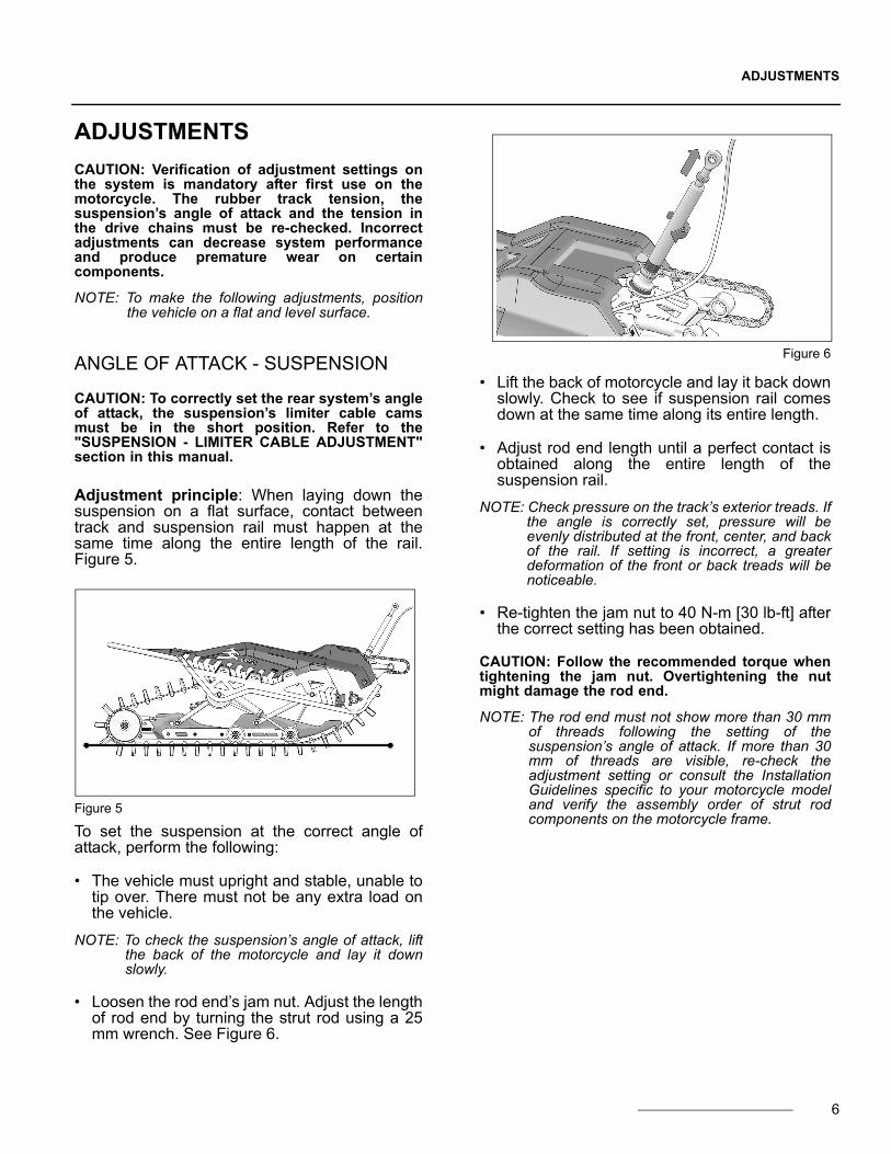
Adjustment principle: When laying down thesuspension on a flat surface, contact betweentrack and suspension rail must happen at thesame time along the entire length of the rail.Figure 5.
Figure 5
To set the suspension at the correct angle ofattack, perform the following:
• The vehicle must upright and stable, unable totip over. There must not be any extra load onthe vehicle.
NOTE: To check the suspension’s angle of attack, liftthe back of the motorcycle and lay it downslowly.
• Loosen the rod end’s jam nut. Adjust the lengthof rod end by turning the strut rod using a 25mm wrench. See Figure 6.
Figure 6
• Lift the back of motorcycle and lay it back downslowly. Check to see if suspension rail comesdown at the same time along its entire length.
• Adjust rod end length until a perfect contact isobtained along the entire length of thesuspension rail.
NOTE: Check pressure on the track’s exterior treads. Ifthe angle is correctly set, pressure will beevenly distributed at the front, center, and backof the rail. If setting is incorrect, a greaterdeformation of the front or back treads will benoticeable.
• Re-tighten the jam nut to 40 N-m [30 lb-ft] afterthe correct setting has been obtained.
CAUTION: Follow the recommended torque whentightening the jam nut. Overtightening the nutmight damage the rod end.
NOTE: The rod end must not show more than 30 mmof threads following the setting of thesuspension’s angle of attack. If more than 30mm of threads are visible, re-check theadjustment setting or consult the InstallationGuidelines specific to your motorcycle modeland verify the assembly order of strut rodcomponents on the motorcycle frame.
6

ADJUSTMENTS
DRIVE CHAIN TENSION
• To make the following setting adjustments, theskin cover must be removed from the rear partof the system.
CAUTION: Some bolts secured on the frame mustbe loosened temporarily to adjust the drive chaintensioner.
• Loosen assembly bolts (1), (2) and (3) on rightside panel to allow the Chain Tensioner (4) topivot on its axis. See Figure 7.
Figure 7
NOTE: it is important that the following steps beperformed in the order prescribed to obtain theoptimal tension setting in the drive chains.
• Adjust the primary drive chain tension (1) byturning adjustment nut (2) at the rear of thetensioner (3) to eliminate play in the primarychain. See Figure 8.
NOTE: Do not finalize the primary drive chainadjustment at this point. Eliminate play in thechain only.
Figure 8
• Adjust next the tension in the secondary drivechain (1) by turning the vertical adjustment nut(2) on the chain tensioner. See Figure 9.
Figure 9
• Apply pressure at center of the two drivesprockets. The chain should have 3-6 mm (1/8-1/4 in.) of play. Re-adjust until the right amountof play is obtained. See Figure 10.
Figure 10
NOTE: Secondary drive chain tension must be setbefore finalizing primary drive chain tensionadjustment.
7

ADJUSTMENTS
• Once the secondary drive chain tension is set,finalize tension adjustment of primary drivechain. Apply pressure at center of the two drivesprockets. The chain should have 3-6 mm (1/8-1/4 in.) of play. Re-adjust until the rightamount of play is obtained. See Figure 11.
Figure 11
CAUTION: After having adjusted the primary drivechain and before tightening the mounting bolts,double-check the secondary drive chain tension.Re-adjust tension if chain deflection does notmeet requirement.
• Re-tighten chain tensioner mounting bolts (1),(2) and (3) to 90 N-m [67 lb-ft] of torque. SeeFigure 12.
Figure 12
• Drive chain tension set too high can causepremature wear on drive sprockets and on thechains themselves. Chains are less likely tocome off and are also less likely to skip on thesprockets.
CAUTION: A chain tension that is set too high willresult in a loss of power and excessivemechanical stress put on drive systemcomponents. A chain tension set too high is notrecommended.
• A lower tension in the drive chains increasesthe risk of chains coming off or skipping on thedrive sprockets.
NOTE: Once the chain tension adjustments are done,double-check to make sure that the tensionsettings are according to specification.
SUSPENSION ADJUSTMENT
The suspension can be adjusted to fit the rider’sweight, personal preferences or type of use madeof the vehicle.
NOTE: Camso recommends that the suspensionspring adjustment be made in a workshop/garage before using the motorcycle.
• Loosen the wheel assembly bolt (1) locatednext to the grooved bushing where the longend of suspension spring sits and remove thewheel. See Figure 13.
Figure 13
• Depress suspension to allow removal of limitercable loop (1) from groove in spring supportbushing. See Figure 14.
Figure 14
8
ADJUSTMENTS
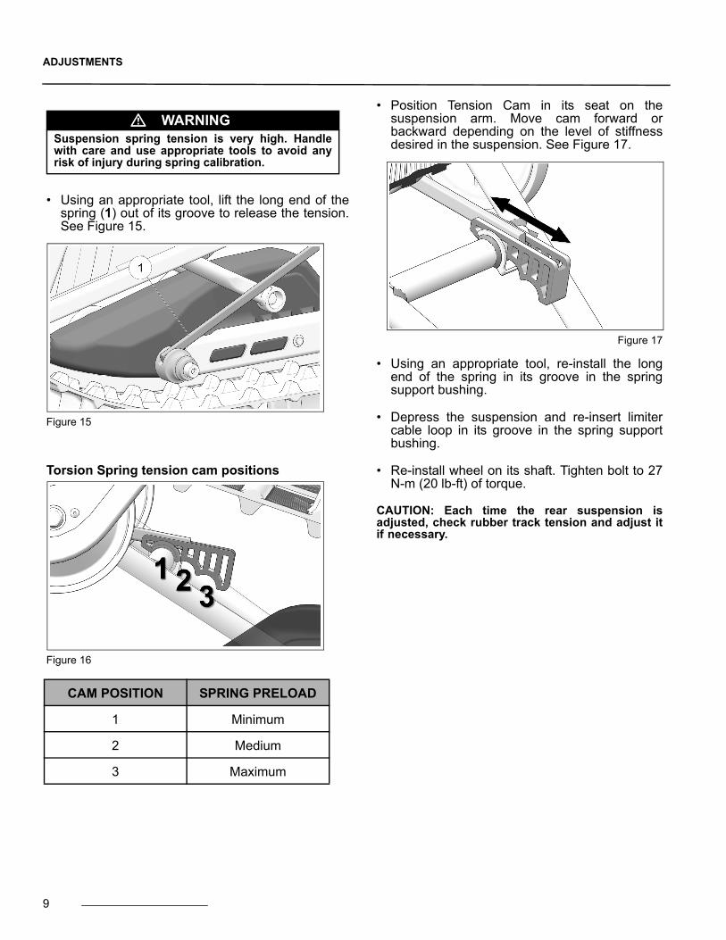
• Using an appropriate tool, lift the long end of thespring (1) out of its groove to release the tension.See Figure 15.
Figure 15
Torsion Spring tension cam positions
Figure 16
• Position Tension Cam in its seat on thesuspension arm. Move cam forward orbackward depending on the level of stiffnessdesired in the suspension. See Figure 17.
Figure 17
• Using an appropriate tool, re-install the longend of the spring in its groove in the springsupport bushing.
• Depress the suspension and re-insert limitercable loop in its groove in the spring supportbushing.
• Re-install wheel on its shaft. Tighten bolt to 27N-m (20 lb-ft) of torque.
CAUTION: Each time the rear suspension isadjusted, check rubber track tension and adjust itif necessary.
� WARNINGSuspension spring tension is very high. Handlewith care and use appropriate tools to avoid anyrisk of injury during spring calibration.
CAM POSITION SPRING PRELOAD
1 Minimum
2 Medium
3 Maximum
9

ADJUSTMENTS
10
SUSPENSION - LIMITER CABLE ADJUSTMENT
Upon reception of the Conversion kit, you will findthe suspension limiter cables adjusted to theshort position. To adjust limiter cables to the longposition, proceed as follows:
• Use a 3 mm Allen key to remove one of thetwo bolts (1) that lock the limiter cable on theupper cam. Figure 18.
Figure 18
• Rotate upper cam (2) 180°. See referencefigures and BASIC TUNING to identify thepreferred cam position. See Figure 19.
Figure 19
• Re-install bolt that was removed to completeadjustment. Figure 20.
Figure 20
CAUTION: Always set cams to the same positionon both sides of the suspension.
BASIC TUNING
• Short position: powder snow conditions.Figure 21.
Figure 21
• Long position: hard-packed snow conditions.Figure 22.
Figure 22
ADJUSTMENTS
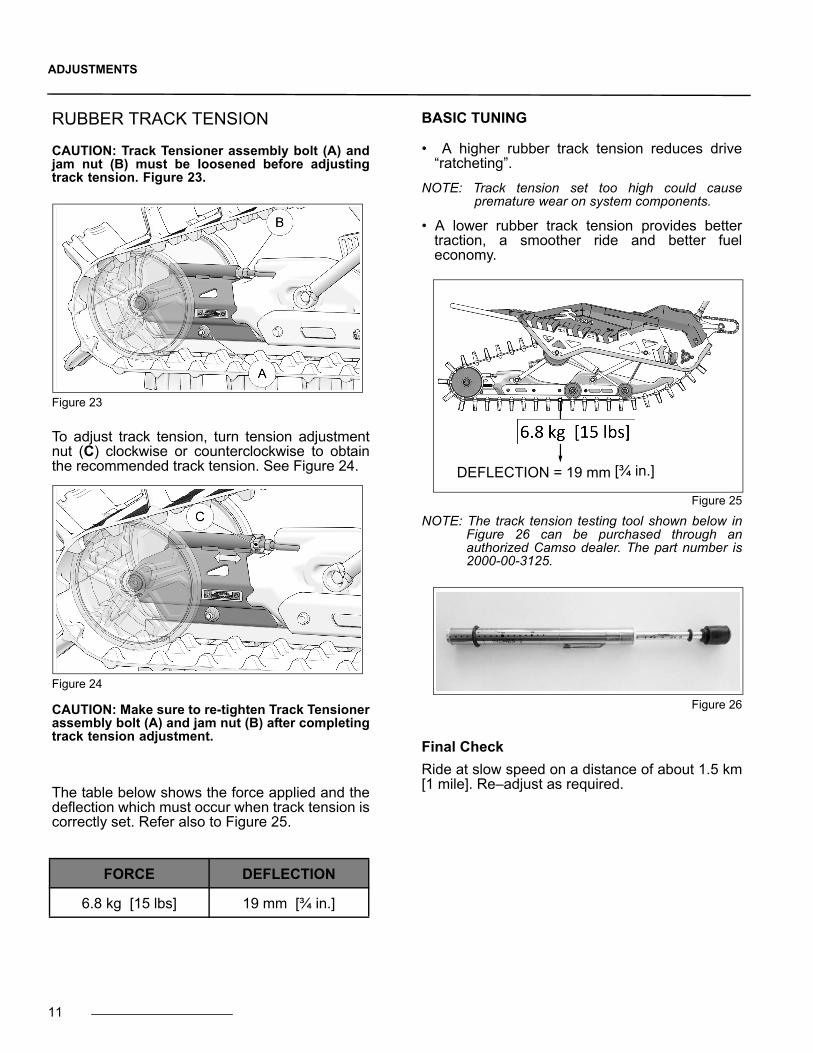
RUBBER TRACK TENSION
CAUTION: Track Tensioner assembly bolt (A) andjam nut (B) must be loosened before adjustingtrack tension. Figure 23.
Figure 23
To adjust track tension, turn tension adjustmentnut (C) clockwise or counterclockwise to obtainthe recommended track tension. See Figure 24.
Figure 24
CAUTION: Make sure to re-tighten Track Tensionerassembly bolt (A) and jam nut (B) after completingtrack tension adjustment.
The table below shows the force applied and thedeflection which must occur when track tension iscorrectly set. Refer also to Figure 25.
BASIC TUNING
• A higher rubber track tension reduces drive“ratcheting”.
NOTE: Track tension set too high could causepremature wear on system components.
• A lower rubber track tension provides bettertraction, a smoother ride and better fueleconomy.
Figure 25
NOTE: The track tension testing tool shown below inFigure 26 can be purchased through anauthorized Camso dealer. The part number is2000-00-3125.
Figure 26
Final Check
Ride at slow speed on a distance of about 1.5 km[1 mile]. Re–adjust as required.
FORCE DEFLECTION
6.8 kg [15 lbs] 19 mm [¾ in.]
DEFLECTION = 19 mm [¾ in.]
11

MAINTENANCE
12
MAINTENANCE
CAUTION: Regular inspection, adjustment andlubrication of the System is essential to its goodrunning order and safe operation. Users have theresponsibility to perform maintenance andregularly adjust their System. The “Maintenance”section provides the necessary information toperform adequate maintenance on the System.
CAUTION: Failure to do regular maintenance at theprescribed intervals and perform the preventiveadjustments indicated in the maintenanceschedule can result in premature wear andimportant breakage on the System that will not becovered under the warranty. The user isresponsible to follow the maintenance scheduleprovided by the manufacturer.
The maintenance schedule has been establishedin order to provide optimum durability for yourSystem. The type of usage and the conditions inwhich the System is used, have a direct bearingon the frequency of maintenance actions toperform. After inspection of your System, you willbe able to determine if the recommendedmaintenance intervals are correct or to adjustthem as needed.
For optimum performance and maximumdurability, please refer to the maintenance chartbelow.
For more details on the maintenance program,consult the Maintenance specifications on page 13and page 14.
� WARNINGDo not insert hands or feet into or near theSystem unless the engine is off, and the vehicle isstopped with the security brake engaged.
INITIALFIRST USE EVERY 25 HRS EVERY 50 HRS EVERY 100 HRS / ANNUAL
SYSTEM - VISUAL INSPECTION CLEAN / INSPECT CLEAN / INSPECT CLEAN / INSPECT CLEAN / INSPECT
SYSTEM - ADJUSTMENTS ADJUST INSPECT / ADJUST INSPECT / ADJUST
SYSTEM - BOLT TORQUE INSPECT / ADJUST
SYSTEM - SPROKETS / CHAINS ADJUST ADJUST / LUBRICATE ADJUST / INSPECT / LUBRICATE ADJUST / REPLACE
SYSTEM - BRAKE INSPECT INSPECT INSPECT
SYSTEM - BEARINGS, TENSIONER INSPECT / LUBRICATE
SYSTEM - BEARINGS, DRIVE SHAFT INSPECT / REPLACE
SYSTEM - CRACKS INSPECT
TRACK - TENSION ADJUST INSPECT / ADJUST INSPECT / ADJUST
TRACK - WEAR INSPECT
WHEELS - WEAR INSPECT
WHEELS - BEARINGS INSPECT INSPECT
WHEELS - SHAFTS LUBRICATE
SUSPENSION - WEAR ON GUIDE INSPECT INSPECT
SUSPENSION - LUBRICATION INSPECT INSPECT / LUBRICATE
SUSPENSION - SPROCKETS INSPECT
SKI - CARBIDE RUNNERS INSPECT INSPECT / REPLACE
SKI - SIDE RUNNERS INSPECT INSPECT INSPECT / REPLACE
SKI - RUBBER DAMPER INSPECT INSPECT
MAINTENANCEINTERVALS

MAINTENANCE
MAINTENANCE - TASKS
• Inspect: Component(s) must be examinedwith care. If an anomaly is noticed, themalfunctioning component(s) must be repairedor replaced.
• Clean: Component(s) must be cleaned of anydirt, dust or contaminant liable to impair theproper operation of the Conversion System.
• Adjust: Component(s) must be adjusted or re-adjusted according to the manufacturer’sadjustment recommendations. Refer to therelevant section of the User Manual.
• Lubricate: Component(s) need to belubricated according to the manufacturer’srecommendations. Refer to the relevantsection of the User Manual.
• Replace: Component(s) must be replaced toavoid serious breakage.
MAINTENANCE - SPECIFICATIONS
System
• Visual Inspection: Visually inspect theSystem’s components to detect any defect oranomaly that can impair its proper functioning.
• Adjustment: Perform or verify angle of attackadjustment on the suspension according to themanufacturer’s recommendations. Refer to theAdjustments section on page 6.
• Bolt Torque: Check the torque of critical boltsidentified in the exploded views of the System.Refer to the central pages of the User Manual.
CAUTION: Comply with the tightening torquerecommendations and use a thread locker productif you come across a bolt that is not tightened tothe manufacturer’s recommendations.
• Chains - Adjustment: Perform or verifytension adjustment on the System’s drivechains according to the manufacturer’srecommendations. Refer to the Adjustmentssection on page 7.
• Sprockets - Wear: Verify wear and generalcondition of sprockets in chain drivemechanism. Refer to “Wear” in theMaintenance section on page 19. Replacesprockets if wear is too great.
• Chains - Wear: Verify wear and generalcondition of chains in drive mechanism. Referto “Wear” in the Maintenance section onpage 17. Replace chains if wear is too great.
• Chains - Lubrication: Lubricate the System’sprimary and secondary drive chains accordingto the maintenance chart. Refer to “Lubrication”in the Maintenance section on page 16.
CAUTION: If a chain is replaced, its sprocketsshould be replaced at the same time. Assembly ofnew and used parts can speed up wear of the newcomponents installed on the drive system.
• Brake Pads - Wear: Verify wear on brakepads. Refer to “Wear” in the Maintenancesection on page 19. Replace brake pads ifwear is too great.
• Brake - Oil Level: With the vehicle upright andon a level surface, check the oil level to makesure that it is over the indicator mark on thebrake’s master cylinder sight glass. Add oil ifneeded.
• Tensioner Bearings: Check Chain tensionerbearings for noise, restriction or abnormal playin rotation. Replace bearings if they show anyone of these defects.
CAUTION: If a bearing shows a defect, replace allthree bearings mounted on the tensioner shaft atthe same time.
• Tensioner - Lubrication : Verify ChainTensioner oil level according to themaintenance chart. Refer to “Lubrication” in theMaintenance section on page 16.
• Drive Shaft Bearings: Check Drive Shaftbearings for restriction, noise or abnormal playin rotation. Bearings must absolutely bereplaced if they present a defect.
• Cracks: Visually inspect the System’s framefor presence of cracks or defects that canimpair proper operation of the System.
Track
• Tension: Set or check track tension on theSystem according to the manufacturer’srecommendations. Refer to “Rubber TrackTension” in the Adjustments section onpage 11.
13

MAINTENANCE
• Wear: Verify wear and overall condition of theSystem’s rubber track. Refer to “Wear” in theMaintenance section on page 18.
CAUTION: A damaged track can result inpremature wear on suspension components.
Wheels
• Wear: Verify general condition of wheels andinspect for wear on the outside diameter ordeformation. Refer to “Wear” in theMaintenance section on page 17. Replacewheel(s) if a defect is present.
• Bearings: Check wheel bearings forrestriction, noise or abnormal play in rotation.Replace wheel bearing if it shows any one ofthese defects.
• Shafts: Remove Wheels. Clean and apply newgrease to wheel shafts.
Suspension
• Guide - Wear: Inspect for wear on SuspensionGuide. Refer to “Wear” in the Maintenancesection on page 18. Replace guide if wear istoo great.
• Suspension Arms - Lubrication: As per themaintenance chart, the suspension arm pivotshafts must be cleaned and lubricated. Referto “Lubrication” in the Maintenance section onpage 16.
• Shock Absorber Upper Mounting Point -Lubrication: As per the maintenance chart,the shock absorber’s upper mounting pointbushing must be cleaned and lubricated. Referto “Lubrication” in the Maintenance section onpage 16.
• Drive Sprockets - Wear: Inspect for wear onthe sprockets driving the rubber track. Refer to“Wear” in the Maintenance section on page 19.Replace the sprockets if wear is too great.
Ski
• Carbide Runners: Inspect general condition ofCarbide Runners. Replace Carbide Runners ifthey show signs of damage or deformation.Refer to “Wear” in the Maintenance section onpage 20.
• Side Runners: Inspect general condition of theski’s Side Runners. Replace Side Runners ifthey show signs of damage or deformation.Refer to “Wear” in the Maintenance section onpage 20.
• Rubber Damper: Inspect general condition ofthe Rubber Damper located on the ski.Replace damper if it is deformed, cracked orshows severe wear. Refer to “Wear” in theMaintenance section on page 18.
Anti-rotation
• Rubber Dampers: Inspect general condition ofthe Rubber Dampers located at the base of theanti-rotation arm. Replace dampers if they aredeformed, cracked or show severe wear. Referto “Wear” in the Maintenance section onpage 18.
14
MAINTENANCE
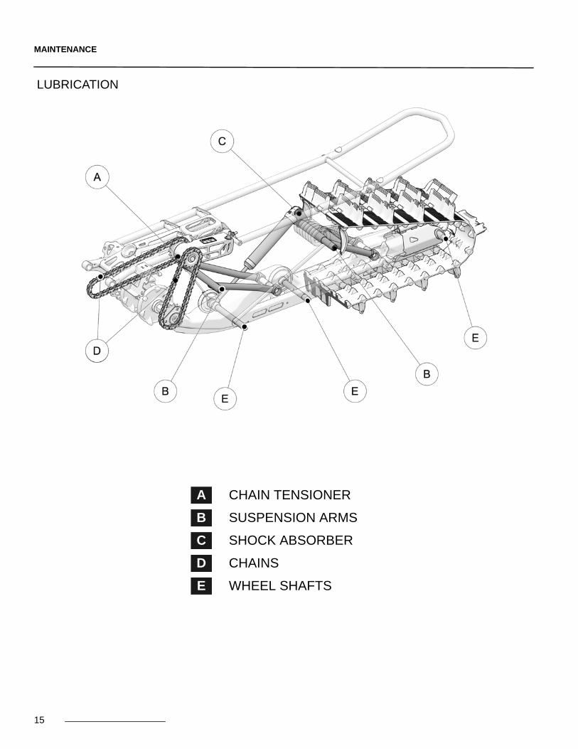
LUBRICATION
A CHAIN TENSIONER
B SUSPENSION ARMS
C SHOCK ABSORBER
D CHAINS
E WHEEL SHAFTS
15

MAINTENANCE
LUBRICATIONThe maintenance chart on page 12 containslubrication maintenance to be performed onthe System. Refer to the followingrecommendations for optimal lubrication.
NOTE: Use lubricants designed for extreme and/orwet environments.
NOTE: Remove Skin to access lubrication pointsshown below.
REFERENCE “A”
CHAIN TENSIONER
Pour 6-8 cc of oil through hole (A) located at frontend of chain tensioner.
NOTE: Use a SAE 80W-90 grade oil designed for highpressure applications.
CAUTION: Do not exceed the recommendedquantity of oil.
REFERENCE “B”
SUSPENSION ARMS
Apply 3-4 cc of grease evenly all around andalong the entire length of the suspension armpivot shafts (B).
NOTE: Tension in the Suspension torsion spring mustbe released before attempting to remove theside panels to grease the suspension armshafts.
REFERENCE “C”
SHOCK ABSORBER UPPER MOUNT
Remove bolt and nut securing upper mount point(C) of shock absorber to suspension arm andapply grease to exterior diameter of shockabsorber’s upper mounting point bushing.
REFERENCE “D”
CHAINS
Apply aerosol grease on the Conversion system’sprimary and secondary drive chains (D).
16

MAINTENANCE
REFERENCE “E”
WHEEL SHAFTS
Apply 1-2 cc of grease evenly all around andalong the length of wheel shafts (E).
WEAR
Wheels
Verify the general condition of the suspension’swheels. If they show important wear or missingfragments, replace the wheel. Check wheelbearings for restriction, noise or abnormal play inrotation. Replace wheel or wheel bearing if theyshow any one of these defects. Figure 27.
Figure 27
Chains
If a chain is adjusted to its highest setting (A) andthe required amount of play (3-6 mm [1/8-1/4 in.])cannot be obtained at the mid point (B) betweenthe sprockets, the chain should be replaced. SeeFigure 28.
Figure 28
CAUTION: If a chain is replaced, the sprocketsshould be replaced at the same time. Assembly ofnew and used parts can speed up wear of the newcomponents installed on the drive system.
17

MAINTENANCE
Track
Verify wear on Track by inspecting the internal (A)and external (B) condition of the Track's carcassrolling path, driving lugs (C), the profile (D). Makesure that the Track’s internal structure is not visibleat cuts or in worn areas. Make sure the steel clips(E) are not abnormally worn. See Figure 28.
Figure 29
Track Guide
Inspect the Track Guide for wear. If the guide isless than 17 mm thick (original thickness -23 mm), anywhere along the entire length,replace the part. See Figure 30.
Figure 30
Rubber Dampers (anti-rotation)
Inspect the Rubber Dampers (A) mounted onstrut rod. Replace them if they show cracks or areexcessively worn or deformed. Figure 31.
CAUTION: An improperly adjusted System candeform and damage the Rubber Dampers. Checkthe adjustment settings if necessary.
Figure 31
Rubber Dampers (ski)
Inspect the Rubber Damper mounted on the ski.Replace the damper if it shows cracks or isexcessively worn or deformed. A deformedRubber Damper does not provide the same levelof support to the ski and affects the steeringbehavior of the motorcycle. Figure 32.
Figure 32
CAUTION: Rubber damper must be correctlyseated in its position. An improperly seated rubberdamper can result in ice accumulating underneathand difficult steering.
18

MAINTENANCE
Brake Pads
Inspect brake pads (A) for wear. If pad thicknessis under 1.6 mm (1/16 in.), replace the parts. SeeFigure 33.
Figure 33
Ball Joint - Anti-rotation Arm
Inspect ball joint on Strut rod. Make sure that it isnot seized or too loose. Figure 34.
CAUTION: A damaged ball joint can make theSystem difficult to adjust and result in damages ifnot replaced.
Figure 34
Track Drive Sprockets
Inspect the Sprockets that drive the Track. If theTrack is set to the required tension (19 mmdeflection for an applied force of 6.8 kg) and thatthe sprockets miss or skip over some of thedriving lugs, the sprockets must be replaced.
Nylon Protector and Guides - chains
Replace nylon protector and guides when theyare worn out and let the chain pass too near theframe. See Figure 35.
Figure 35
Chain Drive Sprockets
Inspect the chain drive sprockets (A) for wear. Ifthe chain is set to the required tension (3-6 mm[1/8-1/4 in.] deflection) and the chain misses orskips over some of the driving teeth, thesprockets must be replaced. Figure 36.
CAUTION: If a chain is replaced, the sprocketsshould be replaced at the same time. Assembly ofnew and used parts can speed up wear of the newcomponents installed on the drive system.
Figure 36
19
MAINTENANCE
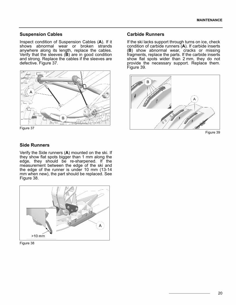
Suspension Cables
Inspect condition of Suspension Cables (A). If itshows abnormal wear or broken strandsanywhere along its length, replace the cables.Verify that the sleeves (B) are in good conditionand strong. Replace the cables if the sleeves aredefective. Figure 37.
Figure 37
Side Runners
Verify the Side runners (A) mounted on the ski. Ifthey show flat spots bigger than 1 mm along theedge, they should be re-sharpened. If themeasurement between the edge of the ski andthe edge of the runner is under 10 mm (13-14mm when new), the part should be replaced. SeeFigure 38.
Figure 38
Carbide Runners
If the ski lacks support through turns on ice, checkcondition of carbide runners (A). If carbide inserts(B) show abnormal wear, cracks or missingfragments, replace the parts. If the carbide insertsshow flat spots wider than 2 mm, they do notprovide the necessary support. Replace them.Figure 39.
Figure 39
20
2-YEAR LIMITED WARRANTY
2-YEAR LIMITED WARRANTYCamso guarantees that the new, unused Camso®
DTS 129 System (System) installed by an authorizeddealer or distributor is free from any defects inmaterials and workmanship during the period and inconditions described below. When operating a newCamso® DTS 129 System, the user agrees that thepresent form is applicable and exclusive, that theyhave been signified and that they have been acceptedby him/her at the time of purchase.The Camso® DTS 129 Dirt-To-Snow bike conversionSystem is covered by a manufacturer warranty(warranty). The warranty covers manufacturing defectsrelated with materials and workmanship. Theinstallation and maintenance of the System is alwaysthe responsibility of the owner.
PERIOD OF COVERAGEThe warranty is valid for a period of twenty-four (24)months following the date of purchase. This warrantydoes not apply to normal maintenance.The warranty applies exclusively to parts andcomponents of the conversion System. All paintdefects on the System (frames and components) arenot covered.The warranty is not valid if the System is not installedby an authorized Camso network dealer or distributor.This warranty specifically excludes any damage orbreakage to the motorcycle and related defects on themotorcycle, whether or not these were caused orbelieved to be caused by the System.The manufacturer is not responsible for damages,injuries or loss caused at the time of or after installingof the System on the motorcycle.For a warranty to be valid, the System owner mustcomply with manufacturer notices and warnings. Inaddition, all claims must be accompanied by a proof ofpurchase (original receipt or sale contract) and work orrepairs must be performed by an authorized Camsodealer. All claims not previously approved andauthorized by Camso will be rejected.
The following situations and items are not underany circumstances covered by the warranty:1) Any and all consequential damages, including, butnot limited to, indirect costs, such as towing, storage,phone calls, renting, transportation, inconveniences,insurance coverage, reimbursement of loss, loss oftime and loss of revenue, etc.2) Damage resulting from faulty installation.3) Damage resulting from normal parts wear orprogressive deterioration owing to the distancecovered with a vehicle on which the System isinstalled.4) Damage resulting in non-compliance with the usermanual and with maintenance instructionsrecommended in the user’s manual and other technicaldocuments.
5) Damage resulting in abusive use, abnormal use,negligence or even a use which does not comply withrecommendations of the manual, excess weight orloading, including excessive number of passengers.6) Labor costs, parts and materials related any and allmaintenance costs.7) Damage resulting from faulty repairs, impropermaintenance or any unauthorized changes made to theSystem other than those specified by the manufactureror from the installation of non-original or unauthorizedparts that were not produced or approved by Camso.8) Damage resulting from an accident, incident,robbery, vandalism, war or unforeseen event or act ofGod.9) Regardless of cause, damage resulting frominexperience, driving errors, accident or other incident.10) The use of the System on a motorcycle used forpublic rental, including by a previous owner, will renderthis warranty null and void.11) The use of the System in races, rallies or othercompetitive events/activities of this type, at any time,including from a previous owner or in conditions that donot comply with those described by the manufacturerwill render the warranty null and void.Any repaired or replaced components or parts areguaranteed only to the extent of the original warranty. inother words: if a warranted part was replaced after nine(9) months, the new replacement part will only beguaranteed for fifteen (15) months, for a total oftwenty–four (24) months. Any claim for a track will beestablished according to its residual value, 100% duringthe first 12 months, 75% between 12 and 18 monthsand 50% between 18 and 24 months. The residualvalue will have to be applied in the form of reduction tothe purchase of a track of replacement at regular price.In no event shall the warranty extend beyond a total oftwenty-four (24) months from the date of originalSystem purchase.In all cases, the warranty is limited to a maximum of theoriginal purchase price or the fair market value of theSystem. Camso will have final authority in determiningthe fair market value of a used System. The warranty isapplicable within the limits and conditions initiallycontracted. If the System is determined to be unusabledue to accident or improper repair, the warranty will beconsidered null and void without further recourseavailable to the System owner.The manufacturer, the retailer and/or the repair shopshall not be held responsible for any delays caused bymaterial, parts or components availability or backorder.*Shipping and handling costs, as well as any feesrelated with shipping or transportation of the System tothe dealer location are the responsibility of the Systemowner.Camso reserves its sole and exclusive right to updateor modify this warranty without impact on end users. Allprevious terms and conditions of the warranty at time ofpurchase will be respected.
21
TROUBLESHOOTING
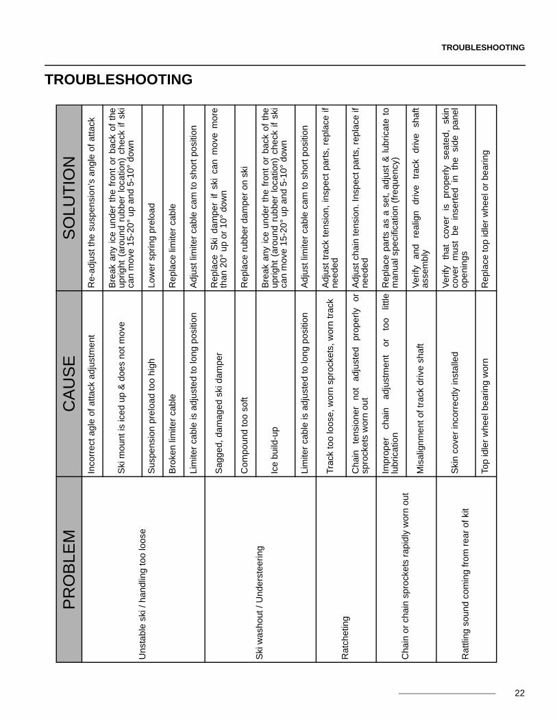
TROUBLESHOOTINGP
RO
BLE
MC
AU
SE
SO
LUT
ION
Uns
tabl
e sk
i / h
andl
ing
too
loos
e
Inco
rre
ct a
gle
of a
ttack
ad
just
me
nt
Re
-adj
ust
the
susp
ensi
on’
s a
ngle
of
atta
ck
Ski
mou
nt
is ic
ed u
p &
doe
s no
t mov
eB
rea
k a
ny i
ce u
nde
r th
e f
ron
t o
r ba
ck o
f th
eup
righ
t (a
rou
nd r
ubbe
r lo
catio
n)
che
ck i
f sk
ica
n m
ove
15-
20°
up
and
5-1
0° d
own
Sus
pen
sion
pre
load
too
hig
hLo
we
r sp
ring
prel
oa
d
Bro
ken
limite
r ca
ble
Re
pla
ce li
mite
r ca
ble
Lim
iter
cabl
e is
ad
just
ed
to lo
ng p
ositi
on
Ad
just
lim
iter
cab
le c
am
to s
ho
rt p
osi
tion
Ski
wa
sho
ut /
Und
ers
tee
ring
Sag
ged
, d
am
ag
ed s
ki d
amp
erR
epla
ce S
ki d
ampe
r if
ski
can
mov
e m
ore
than
20
° u
p o
r 1
0°
dow
n
Co
mp
oun
d to
o so
ftR
epl
ace
rub
ber
dam
per
on s
ki
Ice
bui
ld-u
pB
rea
k a
ny i
ce u
nde
r th
e f
ron
t o
r ba
ck o
f th
eup
righ
t (a
rou
nd r
ubbe
r lo
catio
n)
che
ck i
f sk
ica
n m
ove
15-
20°
up
and
5-1
0° d
own
Lim
iter
cabl
e is
ad
just
ed
to lo
ng p
ositi
on
Ad
just
lim
iter
cab
le c
am
to s
ho
rt p
osi
tion
Rat
chet
ing
Tra
ck t
oo lo
ose,
wo
rn s
pro
cket
s, w
orn
tra
ckA
dju
st t
rack
te
nsio
n,
insp
ect
par
ts,
repl
ace
ifne
ede
d
Ch
ain
te
nsi
on
er
no
t ad
just
ed
pro
per
ly
orsp
rock
ets
wor
n ou
tA
dju
st c
hai
n te
nsi
on.
Insp
ect p
art
s, r
epla
ce if
nee
ded
Cha
in o
r ch
ain
sp
rock
ets
ra
pid
ly w
orn
out
Impr
ope
r ch
ain
a
dju
stm
en
t o
r to
o
little
lubr
icat
ion
Re
pla
ce p
art
s a
s a
set,
ad
just
& l
ubric
ate
tom
anua
l spe
cific
atio
n (
fre
que
ncy
)
Mis
alig
nm
en
t of t
rack
dri
ve s
haf
tV
erify
a
nd
real
ign
d
rive
trac
k d
rive
sh
aft
asse
mb
ly
Rat
tlin
g so
un
d co
min
g fr
om r
ear
of k
itS
kin
cove
r in
corr
ectly
inst
alle
dV
erify
th
at
cove
r is
pr
oper
ly
seat
ed,
skin
cove
r m
ust
be
inse
rted
in
th
e si
de
pane
lop
eni
ngs
Top
idle
r w
heel
bea
ring
wor
nR
epla
ce t
op
idle
r w
hee
l or
bea
ring
22

TROUBLESHOOTING
PR
OB
LEM
CA
US
ES
OLU
TIO
N
Su
spen
sio
n do
es n
ot c
olla
pse
or
tra
vel
Hu
mid
ity h
as ic
ed
up
insi
de
sh
ock
abs
orbe
rS
ho
ck
abso
rber
n
eed
s to
b
e re
pla
ced
o
rta
ken
off f
or m
aint
enan
ce
Un
ders
teer
ing
on
icy
terr
ain
Sid
e ru
nne
r w
orn
out
Re
-sha
rpe
n or
rep
lace
Har
d to
initi
ate
lean
ing
Slid
e is
wor
n ou
tR
epla
ce s
lide
Bra
ke n
eed
s to
be
pum
ped
in o
rder
to
bra
ke(s
pon
gy b
rake
leve
r)
Dis
c b
rake
is b
en
t or
loo
seR
ep
lace
da
mag
ed
part
s. C
heck
tor
que
on
bra
ke h
ub.
Exc
essi
ve ic
e b
uild
-up
on
disc
Pay
at
tent
ion
to
ice
build
-up
in
part
icul
arco
ndi
tion
s
Air
tra
pp
ed in
bra
ke li
ne
Ble
ed
bra
kin
g s
yste
m
Bra
ke s
yste
m is
ha
rd t
o bl
eed
Imp
rope
r br
ake
line
rou
ting
Bra
ke
line
m
ust
be
ro
uted
a
s st
raig
ht
as
pos
sib
le.
Avo
id s
mal
l ra
diu
s be
nds
His
sing
sou
nd w
hen
app
lyin
g b
rake
Bra
ke p
ads
are
loo
se o
r w
orn
out
Ve
rify
inst
alla
tion
or
repl
ace
pa
ds
Bik
e ha
rd to
sta
rt (
too
rich)
Air
te
mp
era
ture
se
nsor
tr
appe
d
in
sno
w(p
erm
ane
nt c
old
sta
rt m
ode)
Re
loca
te
Air
tem
pera
ture
se
nsor
or
in
stal
lp
re-f
ilte
r o
n s
ens
or
23

PARTS LIST
24
PARTS LIST
ITEM PART # DESCRIPTION QTY
CAMSO DTS 129 MY2018 :: FRONT SKI ASSEMBLY
1 1032-10-H030 HSCS, M10-1.5X30, 12.9, ZP, TL, DIN 912 2
2 1035-08-C050 HFCS, M8-1.25X50, 10.9, ZP, IFI536 2
3 1036-10-4030 HFSCS, M10-1.5X30, 10.9, ZP, TL, DIN 6921 4
4 1038-08-K020 HSFBS, M8-1.25X20, SS, 18-8 8
5 1060-00-0001 W, 11/16X11/32X0.060, 8, ZP, SAE 4
6 1074-08-0001 FNN, M8-1.25, 8, ZP, DIN6926 14

PARTS LIST
25
ITEM PART # DESCRIPTION QTY
CAMSO DTS 129 MY2018 :: REAR SUSPENSION
1 1016-00-9162 IDLER WHEEL 162MM / ROUE INTERMÉDIAIRE 162MM 2
2 1032-04-J010 SHCS, M4-0.7X10, 12.9, ZP, DIN912 4
3 1033-06-0150 HCS, M6-1.0X150, 8.8, ZP, ISO4014 3
4 1035-10-1045 HFCS, M10-1.5X45, 10.9, ZP, DIN6921 1
5 1036-08-0025 HFSCS, M8-1.25X25, 8.8, ZP, DIN6921 8
6 1036-10-4030 HFSCS, M10-1.5X30, 10.9, ZP, TL, DIN6921 8
7 1046-10-0080 CB, M10-1.5X80, 8.8, ZP, DIN603 1
8 1060-00-0004 W, 7/16X1.0X0.072, 8, ZP, USS 4
9 1060-06-0001 W, 6.4X20X1.5, ZP, DIN9021 6
10 1060-08-0001 W, 24X8.4X2, ZP, DIN9021 6
11 1060-10-0001 W, 20X10.5X2, ZP, DIN125A 1
12 1074-06-0001 FNN, M6-1, 8, ZP, DIN6926 3
13 1074-10-0001 FNN, M10-1.5, 8, ZP, DIN6926 2
14 1082-00-7550 TENSIONER ROD ASS'Y / TIGE TENSIONNEUR ASSEMBLÉ 1
15 1089-00-9026 SHOCK, SLEEVE / AMORTISSEUR, DOUILLE 1
16 1430-06-X016 RWHS, 6X16, TX, ZP 1

PARTS LIST
ITEM PART # DESCRIPTION QTY
CAMSO DTS 129 MY2018 :: FRAME ASSEMBLY
1 1009-00-9019 SPROCKET, 520, 19 TEETH / BARBOTIN, 520, 19 DENTS 1
2 1033-10-2026 HCSW, M10-1.5X25, 8.8, ZP, TL, DIN933 2
3 1035-12-1100 HFCS, M12-1.75X100 ,10.9, ZP, DIN6921 1
4 1036-08-0025 HFSCS, M8-1.25X25, 8.8, ZP, DIN6921 3
5 1046-08-0020 CB, M8-1.25X20, 8.8, ZP 3
6 1060-08-0001 W, 24X8.4X2, ZP, DIN9021 1
7 1074-08-0001 FNN, M8-1.25, 8, ZP, DIN6926 4
8 1178-08-0001 CLN, M8-1.25, BP 4
9 1430-06-X016 RWHS, 6X16, TX, ZP 2
26

PARTS LIST
ITEM PART # DESCRIPTION QTY
CAMSO DTS 129 MY2018 :: REAR SUSPENSION ASSEMBLY
1 7087-00-9024 S-KIT, SUSPENSION ASSY/ SUSPENSION ASSEMBLÉE 1
2 1036-10-4030 HFSCS, M10-1.5X30, 10.9, ZP, TL, DIN 6921 4
3 1060-00-0004 W, 7/16X1.0X0.072, 8, ZP, USS 4
4 -- REAR SUSPENSION, SUB ASSY / SOUS-ENS, SUSP. ARRIÈRE 1
ITEM PART # DESCRIPTION QTY
CAMSO DTS 129 MY2018 :: 94MM WHEEL ASSEMBLY
1 7016-00-9094 S-KIT, WHEEL 94MM / ROUE 94MM 1
2 -- WHEEL 94MM / ROUE 94MM 1
3 1036-08-0025 HFSCS, M8-1.25X25, 8.8 ,ZP, DIN6921 1
4 1060-08-0001 W, 24X8.4X2, ZP, DIN9021 1
27

PARTS LIST
ITEM PART # DESCRIPTION QTY
CAMSO DTS 129 MY2018 :: FRONT SUSPENSION ARM
1 7087-00-9355 S-KIT, FRONT SUSPENSION ARM / BRAS SUSPENSION AVANT 1
2 1036-10-4030 HFSCS, M10-1.5X30, 10.9, ZP, TL, DIN 6921 4
3 1060-00-0004 W, 7/16X1.0X0.072, 8, ZP, USS 2
4 -- FRONT SUSPENSION A-ARM / BRAS SUSPENSION AVANT 1
5 4000-00-9091 A-ARM SHAFT / ARBRE, BRAS SUSPENSION 1
6 4000-00-9327 SUSPENSION A-ARM, SHAFT / BRAS SUSPENSION, ARBRE 1
ITEM PART # DESCRIPTION QTY
CAMSO DTS 129 MY2018 :: 104MM WHEEL ASSEMBLY
1 7016-00-9104 S-KIT, WHEEL 104MM / ROUE 104MM 1
2 -- WHEEL 104MM / ROUE 104MM 1
3 1036-08-0025 HFSCS, M8-1.25X25, 8.8, ZP, DIN6921 1
4 1060-08-0001 W, 24X8.4X2, ZP, DIN9021 1
5 1087-00-9023 WHEEL SPACER / ESPACEUR DE ROUE 1
28

PARTS LIST
29
ITEM PART # DESCRIPTION QTY
CAMSO DTS 129 MY2018 :: REAR SUSPENSION ARM
1 7087-00-9290 S-KIT, REAR SUSPENSION ARM / BRAS SUSPENSION ARRIERE 1
2 1016-00-9162 IDLER WHEEL, 162MM / ROUE INTERMÉDIAIRE, 162MM 2
3 1036-10-4030 HFSCS, M10-1.5X30, 10.9, ZP, TL, DIN 6921 4
4 1060-00-0004 W, 7/16X1.0X0.072, 8, ZP, USS 2
5 -- REAR SUSPENSION A-ARM / BRAS SUSPENSION ARRIÈRE 1
6 4000-00-9091 A-ARM SHAFT / ARBRE, BRAS SUSPENSION 1
7 4000-00-9327 SUSPENSION A-ARM, SHAFT / BRAS SUSPENSION, ARBRE 1
ITEM PART # DESCRIPTION QTY
CAMSO DTS 129 MY2018 :: 162MM IDLER WHEEL
1 1016-00-9162 IDLER WHEEL 162MM / ROUE INTERMÉDIAIRE 162MM 1

PARTS LIST
ITEM PART # DESCRIPTION QTY
CAMSO DTS 129 MY2018 :: TORSION SPRING
1 7080-00-9006 S-KIT, TORSION SPRING / RESSORT DE TORSION 1
2 -- TORSION SPRING / RESSORT DE TORSION 1
3 1087-00-9053 SPRING HOLDER / SUPPORT RESSORT 1
4 1087-00-9154 SLEEVE / MANCHON 1
5 1092-00-9033 SPRING CAM / CAME, RESSORT 1
ITEM PART # DESCRIPTION QTY
CAMSO DTS 129 MY2018 :: SHOCK ABSORBER
1 7089-00-9485 S-KIT, SHOCK ABSORBER / AMORTISSEUR 1
2 1035-10-1045 HFCS, M10-1.5X45, 10.9, ZP, DIN6921 1
3 1074-10-0001 FNN, M10-1.5, 8, ZP, DIN6926 1
4 1089-00-9026 SHOCK, SLEEVE / AMORTISSEUR, DOUILLE 1
5 -- SHOCK ABSORBER / AMORTISSEUR SUSPENSION 1
30

PARTS LIST
31
ITEM PART # DESCRIPTION QTY
CAMSO DTS 129 MY2018 :: 200MM WHEEL ASSEMBLY
1 7016-00-9200 S-KIT, WHEEL 200MM / ROUE 200MM 1
2 -- WHEEL 200MM / ROUE 200MM 1
3 1036-08-0025 HFSCS, M8-1.25X25, 8.8, ZP, DIN6921 1
4 1060-08-0001 W, 24X8.4X2, ZP, DIN9021 1
ITEM PART # DESCRIPTION QTY
CAMSO DTS 129 MY2018 :: STICKER KIT
1 7083-00-9065 S-KIT, STICKER DTS / COLLANT DTS 1
2 -- STICKER - LOOSEN PRIOR / DÉCALQUE DESSERRER AVANT 1
3 -- STICKER WARNING / AUTOCOLLANT AVERTISSEMENT 1
4 -- STICKER DAMPER - SKIN COVER / DÉCALQUE AMORTISSEUR 2
5 -- STICKER, CAMSO LOGO / DÉCALQUE LOGO CAMSO 1
6 -- STICKER SKIN, LH / COLLANT CAPOT, GA 1
7 -- STICKER SIDE PANEL, LH / COLLANT PANNEAU LATÉRAL, GA 1
8 -- STICKER SKIN, RH / COLLANT CAPOT, DR 1
9 -- STICKER SIDE PANEL, RH / COLLANT PANNEAU LATÉRAL, DR 1
10 -- STICKER, SIDE PANEL TUBE / COLLANT, TUBE, PANNEAU LATÉRAL 2

PARTS LIST
32
ITEM PART # DESCRIPTION QTY
CAMSO DTS 129 MY2018 :: SUSPENSION RAIL
1 7087-00-9080 S-KIT, SUSPENSION RAIL ASSY / RAIL SUSPENSION ASS. 1
2 1033-06-0150 HCS, M6-1.0X150, 8.8, ZP, ISO4014 3
3 1036-08-0025 HFSCS, M8-1.25X25, 8.8, ZP, DIN6921 2
4 1060-06-0001 W, 6.4X20X1.5, ZP, DIN9021 6
5 1074-06-0001 FNN, M6-1, 8, ZP, DIN6926 3
6 -- SUSPENSION, RAIL STIFFENER - LH / RENFORT RAIL - GA 1
7 -- SUSPENSION, RAIL STIFFENER - RH / RENFORT RAIL - DR 1
8 -- SUSPENSION, RAIL & RIVET NUTS / RAIL & ÉCROUS À SERTIR 1
9 -- BASE SHAFT / ARBRE BASE 3
10 4000-00-9207 IDLER SHORT SHAFT / ARBRE RENVOI COURT 1
11 4000-00-9266 IDLER LONG SHAFT / ARBRE RENVOI LONG 1
ITEM PART # DESCRIPTION QTY
CAMSO DTS 129 MY2018 :: TRACK SLIDE
1 7085-00-9321 S-KIT, TRACK SLIDE / S-KIT, GLISSIÈRE CHENILLE 1
2 -- SLIDE, 129 / GLISSIÈRE, 129 1
3 1430-06-X016 RWHS, 6X16, TX, ZP 1

PARTS LIST
33
ITEM PART # DESCRIPTION QTY
CAMSO DTS 129 MY2018 :: TRACK TENSIONER
1 7014-00-9230 S-KIT, TRACK TENSIONER / TENDEUR DE CHENILLE 1
2 -- TENSIONER, ASSY / TENDEUR, ASSEMBLÉ 1
3 1046-10-0080 CB, M10-1.5X80, 8.8, ZP, DIN603 1
4 1060-10-0001 W, 20X10.5X2, ZP, DIN125A 1
5 1074-10-0001 FNN, M10-1.5, 8, ZP, DIN6926 1
6 1082-00-7550 TENSIONER ROD ASS'Y / TIGE TENSIONNEUR ASSEMBLÉ 1
7 -- STICKER - LOOSEN PRIOR / DÉCALQUE, DESSERRER AVANT 1
ITEM PART # DESCRIPTION QTY
CAMSO DTS 129 MY2018 :: ANTI-ROTATION ROD
1 7001-00-9240 ANTI-ROTATION ROD ASSY / TUBE ANTI-ROTATION ASSEMBLÉ 1
2 -- ANTI-ROTATION ROD / TIGE ANTI-ROTATION 1
3 1036-12-4030 HFSCS, M12-1.75X30, 10.9, ZP, TL, DIN 6921 1
4 1047-16-1065 ROD END, M16-1.5X65, ASSY / TIGE EMBOUT, M16-1.5X65, ASS 1
5 1051-00-9030 SPACER, ANTI-ROTATION / ESPACEUR ANTI-ROTATION 1
6 1093-00-9060 RUBBER DAMPER / AMORTISSEUR DE CAOUTCHOUC 3
7 -- TAG - STRUT ROD DTS 129 / ÉTIQUETTE - BRAS COUPLAGE DTS 129 1

PARTS LIST
ITEM PART # DESCRIPTION QTY
CAMSO DTS 129 MY2018 :: MAIN FRAME
1 7018-00-9270 S-KIT, MAIN FRAME / S-KIT, CHÂSSIS 1
2 -- FRAME - DTS / CHÂSSIS - DTS 1
3 -- STICKER DAMPER - SKIN COVER / DÉCALQUE AMORTISSEUR 2
4 1178-08-0001 CLN, M8-1.25, BP 4
ITEM PART # DESCRIPTION QTY
CAMSO DTS 129 MY2018 :: DRIVE SIDE BEARING ASS’Y
1 7090-00-9205 S-KIT, BEARING DRIVE SIDE /ROULEMENT, CÔTÉ ENTRAÎNEMENT 1
2 1033-10-2026 HCSW, M10-1.5X25, 8.8, ZP, TL, DIN933 1
3 1046-08-0020 CB, M8-1.25X20, 8.8, ZP 3
4 1074-08-0001 FNN, M8-1.25, 8, ZP, DIN6926 3
5 -- BEARING / ROULEMENT -- AS205-014 1
6 -- BEARING FLANGE / BRIDE DE SOUTIEN ROULEMENT -- PFT205 2
34
PARTS LIST
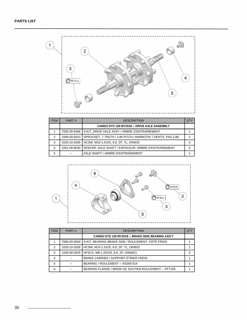
ITEM PART # DESCRIPTION QTY
CAMSO DTS 129 MY2018 :: DRIVE AXLE ASSEMBLY
1 7000-00-9406 S-KIT, DRIVE AXLE ASSY / ARBRE D’ENTRAÎNEMENT 1
2 1009-00-9310 SPROCKET, 7 TEETH / 2.86 PITCH / BARBOTIN 7 DENTS, PAS 2.86 2
3 1033-10-2026 HCSW, M10-1.5X25, 8.8, ZP, TL, DIN933 2
4 1051-00-9020 SPACER, AXLE SHAFT / ESPACEUR, ARBRE D’ENTRAÎNEMENT 2
5 -- AXLE SHAFT / ARBRE D’ENTRAÎNEMENT 1
ITEM PART # DESCRIPTION QTY
CAMSO DTS 129 MY2018 :: BRAKE SIDE BEARING ASS’Y
1 7086-00-9004 S-KIT, BEARING BRAKE SIDE / ROULEMENT, CÔTÉ FREIN 1
2 1033-10-2026 HCSW, M10-1.5X25, 8.8, ZP, TL, DIN933 1
3 1036-08-0025 HFSCS, M8-1.25X25, 8.8, ZP, DIN6921 3
4 -- BRAKE CARRIER / SUPPORT ÉTRIER FREIN 1
5 -- BEARING / ROULEMENT -- AS205-014 1
6 -- BEARING FLANGE / BRIDE DE SOUTIEN ROULEMENT -- PFT205 1
35

PARTS LIST
ITEM PART # DESCRIPTION QTY
CAMSO DTS 129 MY2018 :: BRAKE ROTOR ASS’Y
1 7086-00-9023 S-KIT, BRAKE ROTOR ASSY / ENSEMBLE ROTOR FREIN 1
2 1032-06-J020 SHCS, M6-1X20, 12.9, ZN, DIN912 6
3 -- BRAKE ROTOR / DISQUE DE FREIN 1
4 -- ROTOR HUB / MOYEU DE ROTOR 1
ITEM PART # DESCRIPTION QTY
CAMSO DTS 129 MY2018 :: TRACK
1 1093-00-9339 TRACK - SNOWBIKE 129" (9339S) / CHENILLE - SNOWBIKE 129" (9339S) 1
36

PARTS LIST
ITEM PART # DESCRIPTION QTY
CAMSO DTS 129 MY2018 :: RIGHT SIDE PANEL
1 7018-00-9025 S-KIT, DTS SIDE PANEL - RH / PANNEAU LATÉRAL DROIT 1
2 1017-00-9026 SQUARE RIBBED PLUG / CAPUCHON TUBE CARRÉ 2
3 -- SIDE PANEL, RH, ASS’Y / PANNEAU LATÉRAL DROIT ASSEMBLÉ 1
4 1037-00-0003 MOUNTABLE CABLE TIE / ATTACHE CÂBLE 2
5 1066-B3-X010 RF, SS, 3/16 X .38 4
6 -- STICKER, CAMSO LOGO / DÉCALQUE, LOGO CAMSO 1
7 -- STICKER, SIDE PANEL, RH / DÉCALQUE, PANNEAU LATÉRAL, DR 1
8 -- STICKER, SIDE PANEL TUBE / DÉCALQUE, PANNEAU LATÉRAL, TUBE 1
9 1087-00-9016 SUSPENSION ARM WEAR PLATE / SUSP., PLAQUE D’USURE 2
10 1179-08-0001 CLN,M8-1.25,BP 3
37

PARTS LIST
ITEM PART # DESCRIPTION QTY
CAMSO DTS 129 MY2018 :: LEFT SIDE PANEL
1 7018-00-9015 S-KIT, DTS SIDE PANEL - LH / PANNEAU LATÉRAL GAUCHE 1
2 -- TENSIONER, PLATE / TENDEUR, PLAQUE 1
3 1017-00-9026 SQUARE RIBBED PLUG / CAPUCHON TUBE CARRÉ 2
4 -- SIDE PANEL, LH, ASSY / PANNEAU LATÉRAL GAUCHE ASSEMBLÉ 1
5 1066-B3-X010 RF, SS, 3/16 X .38 4
6 1066-B3-X016 RF, SS, 3/16 X .63 4
7 -- STICKER, CAMSO LOGO / DÉCALQUE, LOGO CAMSO 1
8 -- STICKER, SIDE PANEL, LH / DÉCALQUE, PANNEAU LATÉRAL, GA 1
9 -- STICKER, SIDE PANEL TUBE / DÉCALQUE, PANNEAU LATÉRAL, TUBE 1
10 1087-00-9016 SUSPENSION ARM WEAR PLATE / SUSP., PLAQUE D’USURE 2
11 1179-08-0001 CLN, M8-1.25, BP 3
12 1278-08-X029 RN, M8-1.25, 0.5-7.1, ZP 1
38
PARTS LIST
39
ITEM PART # DESCRIPTION QTY
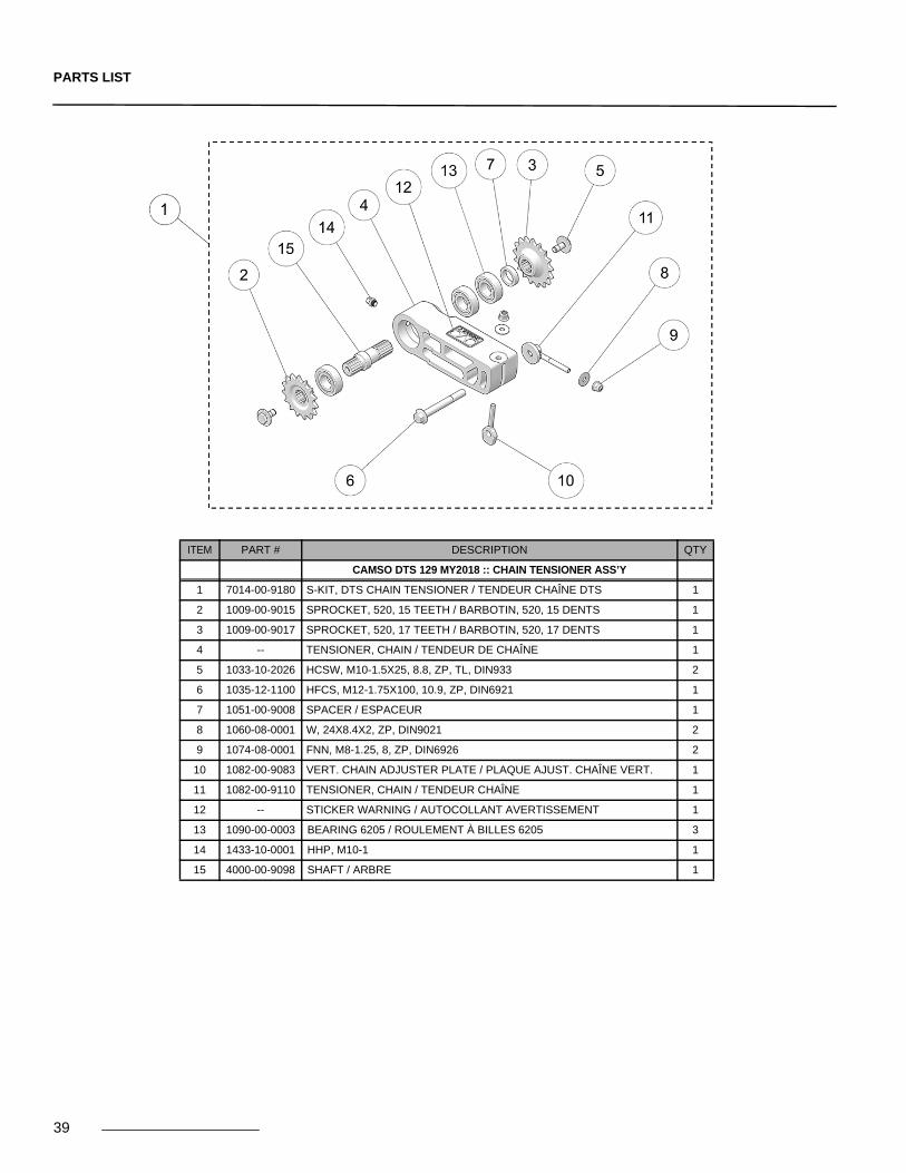
CAMSO DTS 129 MY2018 :: CHAIN TENSIONER ASS’Y
1 7014-00-9180 S-KIT, DTS CHAIN TENSIONER / TENDEUR CHAÎNE DTS 1
2 1009-00-9015 SPROCKET, 520, 15 TEETH / BARBOTIN, 520, 15 DENTS 1
3 1009-00-9017 SPROCKET, 520, 17 TEETH / BARBOTIN, 520, 17 DENTS 1
4 -- TENSIONER, CHAIN / TENDEUR DE CHAÎNE 1
5 1033-10-2026 HCSW, M10-1.5X25, 8.8, ZP, TL, DIN933 2
6 1035-12-1100 HFCS, M12-1.75X100, 10.9, ZP, DIN6921 1
7 1051-00-9008 SPACER / ESPACEUR 1
8 1060-08-0001 W, 24X8.4X2, ZP, DIN9021 2
9 1074-08-0001 FNN, M8-1.25, 8, ZP, DIN6926 2
10 1082-00-9083 VERT. CHAIN ADJUSTER PLATE / PLAQUE AJUST. CHAÎNE VERT. 1
11 1082-00-9110 TENSIONER, CHAIN / TENDEUR CHAÎNE 1
12 -- STICKER WARNING / AUTOCOLLANT AVERTISSEMENT 1
13 1090-00-0003 BEARING 6205 / ROULEMENT À BILLES 6205 3
14 1433-10-0001 HHP, M10-1 1
15 4000-00-9098 SHAFT / ARBRE 1
PARTS LIST
40
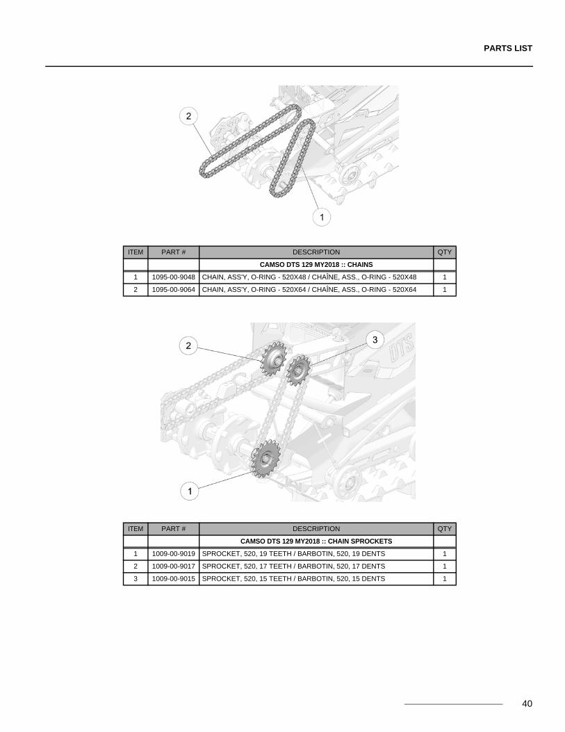
ITEM PART # DESCRIPTION QTY
CAMSO DTS 129 MY2018 :: CHAINS
1 1095-00-9048 CHAIN, ASS'Y, O-RING - 520X48 / CHAÎNE, ASS., O-RING - 520X48 1
2 1095-00-9064 CHAIN, ASS'Y, O-RING - 520X64 / CHAÎNE, ASS., O-RING - 520X64 1
ITEM PART # DESCRIPTION QTY
CAMSO DTS 129 MY2018 :: CHAIN SPROCKETS
1 1009-00-9019 SPROCKET, 520, 19 TEETH / BARBOTIN, 520, 19 DENTS 1
2 1009-00-9017 SPROCKET, 520, 17 TEETH / BARBOTIN, 520, 17 DENTS 1
3 1009-00-9015 SPROCKET, 520, 15 TEETH / BARBOTIN, 520, 15 DENTS 1

PARTS LIST
41
ITEM PART # DESCRIPTION QTY
CAMSO DTS 129 MY2018 :: CHAIN GUIDE KIT
1 7085-00-9061 S-KIT, CHAIN GUIDE SET / ENS. GUIDE CHAÎNE 1
2 CHAIN GUIDE / GUIDE DE CHAÎNE 1
3 -- SLEEVE, NYLON / DOUILLE, NYLON 1
4 -- BLOCK, CHAIN GUIDE / BLOC, GUIDE DE CHAÎNE 1
5 1278-08-X029 RN, M8-1.25, 0.5-7.1, ZP 1
6 1430-06-X016 RWHS, 6X16, TX, ZP 2
ITEM PART # DESCRIPTION QTY
CAMSO DTS 129 MY2018 :: SKIN COVER
1 7087-00-9009 S-KIT, SKIN COVER DTS / COUVRE TUNNEL DTS 1
2 1036-08-0025 HFSCS, M8-1.25X25, 8.8, ZP, DIN6921 6
3 1060-08-0001 W, 24X8.4X2, ZP, DIN9021 6
4 -- STICKER DAMPER - SKIN COVER / DÉCALQUE AMORTISSEUR 2
5 -- STICKER, CAMSO LOGO / DÉCALQUE LOGO CAMSO 1
6 -- STICKER, DTS 129 / DÉCALQUE DTS 129 2
7 -- STICKER SKIN, LH / COLLANT CAPOT, GA 1
8 -- STICKER SKIN, RH / COLLANT CAPOT, DR 1
9 -- SKIN COVER / COUVRE TUNNEL 1
10 1179-08-0001 CLN, M8-1.25, BP 6

PARTS LIST
ITEM PART # DESCRIPTION QTY
CAMSO DTS 129 MY2018 :: BRAKE SYSTEM
1 7086-00-9070 S-KIT, BRAKE SYSTEM DTS / S-KIT, SYSTÈME FREIN DTS 1
2 1032-08-J065 HSCS, M8-1.25X65, 12.9, ZN, DIN912 2
3 1037-00-0003 MOUNTABLE CABLE TIE / ATTACHE CÂBLE 2
4 1037-00-0037 LOOP CLAMP / BRIDE DE FIXATION 1
5 1249-E1-X016 SDHWS, #10-16X5/8, ZP 1
6 1086-00-9190 BRAKE LINE ASS’Y, 1847 MM / CONDUITE FREIN ASS., 1847 MM 1
7 7086-00-9010 S-KIT, BRAKE CALIPER / S-KIT, ÉTRIER DE FREIN 1
8 7086-00-9011 S-KIT, BREAK PADS / S-KIT, PLAQUETTES DE FREIN 1
9 7086-00-9012 S-KIT, MASTER CYLINDER - RH / S-KIT, MAÎTRE CYLINDRE, DR 1
10 7086-00-9013 S-KIT, BRAKE LINE FASTENERS / QUINCAILLERIE SYSTÈME FREIN 2
11 7086-00-9014 S-KIT, BRAKE LEVER / LEVIER DE FREIN 1
12 7086-00-9015 S-KIT, MASTER CYLINDER, CLAMP/ SYSTÈME FREIN, BRIDE 1
42
PARTS LIST
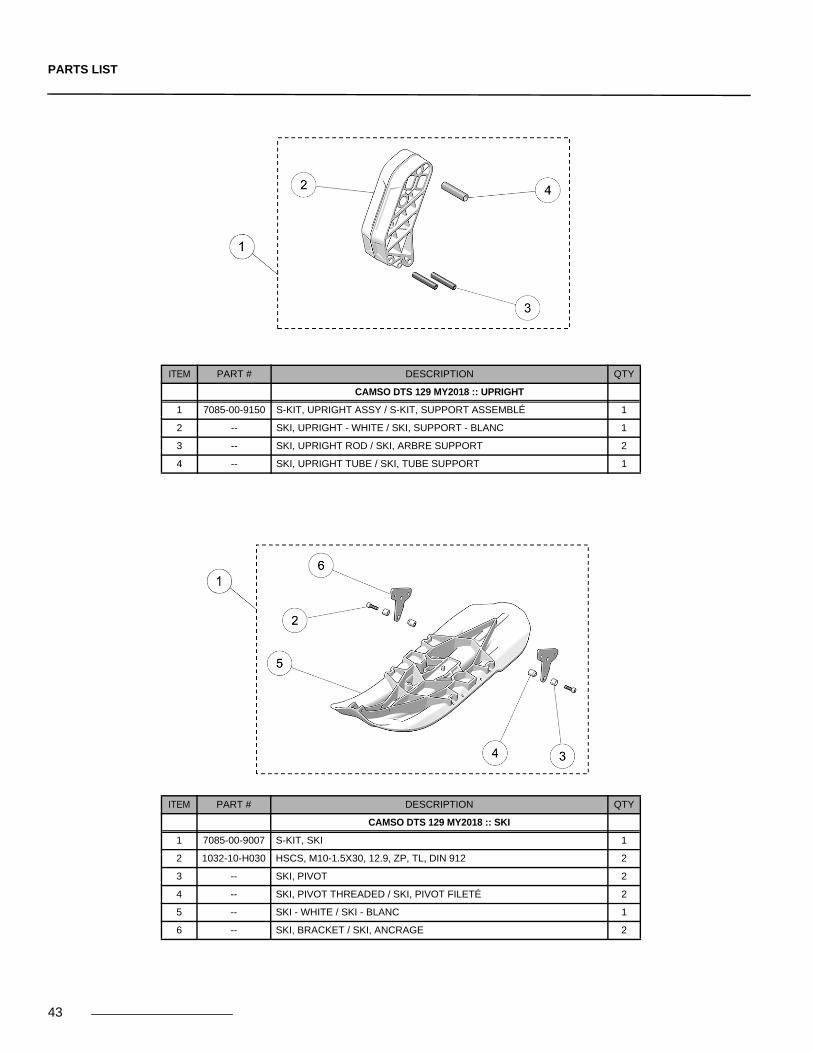
ITEM PART # DESCRIPTION QTY
CAMSO DTS 129 MY2018 :: UPRIGHT
1 7085-00-9150 S-KIT, UPRIGHT ASSY / S-KIT, SUPPORT ASSEMBLÉ 1
2 -- SKI, UPRIGHT - WHITE / SKI, SUPPORT - BLANC 1
3 -- SKI, UPRIGHT ROD / SKI, ARBRE SUPPORT 2
4 -- SKI, UPRIGHT TUBE / SKI, TUBE SUPPORT 1
ITEM PART # DESCRIPTION QTY
CAMSO DTS 129 MY2018 :: SKI
1 7085-00-9007 S-KIT, SKI 1
2 1032-10-H030 HSCS, M10-1.5X30, 12.9, ZP, TL, DIN 912 2
3 -- SKI, PIVOT 2
4 -- SKI, PIVOT THREADED / SKI, PIVOT FILETÉ 2
5 -- SKI - WHITE / SKI - BLANC 1
6 -- SKI, BRACKET / SKI, ANCRAGE 2
43
PARTS LIST
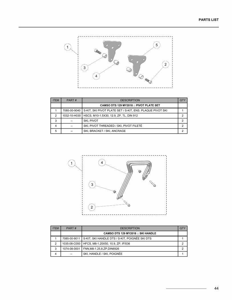
ITEM PART # DESCRIPTION QTY
CAMSO DTS 129 MY2018 :: PIVOT PLATE SET
1 7085-00-9040 S-KIT, SKI PIVOT PLATE SET / S-KIT, ENS. PLAQUE PIVOT SKI 1
2 1032-10-H030 HSCS, M10-1.5X30, 12.9, ZP, TL, DIN 912 2
3 -- SKI, PIVOT 2
4 -- SKI, PIVOT THREADED / SKI, PIVOT FILETÉ 2
5 -- SKI, BRACKET / SKI, ANCRAGE 2
ITEM PART # DESCRIPTION QTY
CAMSO DTS 129 MY2018 :: SKI HANDLE
1 7085-00-9011 S-KIT, SKI HANDLE DTS / S-KIT, POIGNÉE SKI DTS 1
2 1035-08-C050 HFCS, M8-1.25X50, 10.9, ZP, IFI536 2
3 1074-08-0001 FNN,M8-1.25,8,ZP,DIN6926 2
4 -- SKI, HANDLE / SKI, POIGNÉE 1
44
PARTS LIST
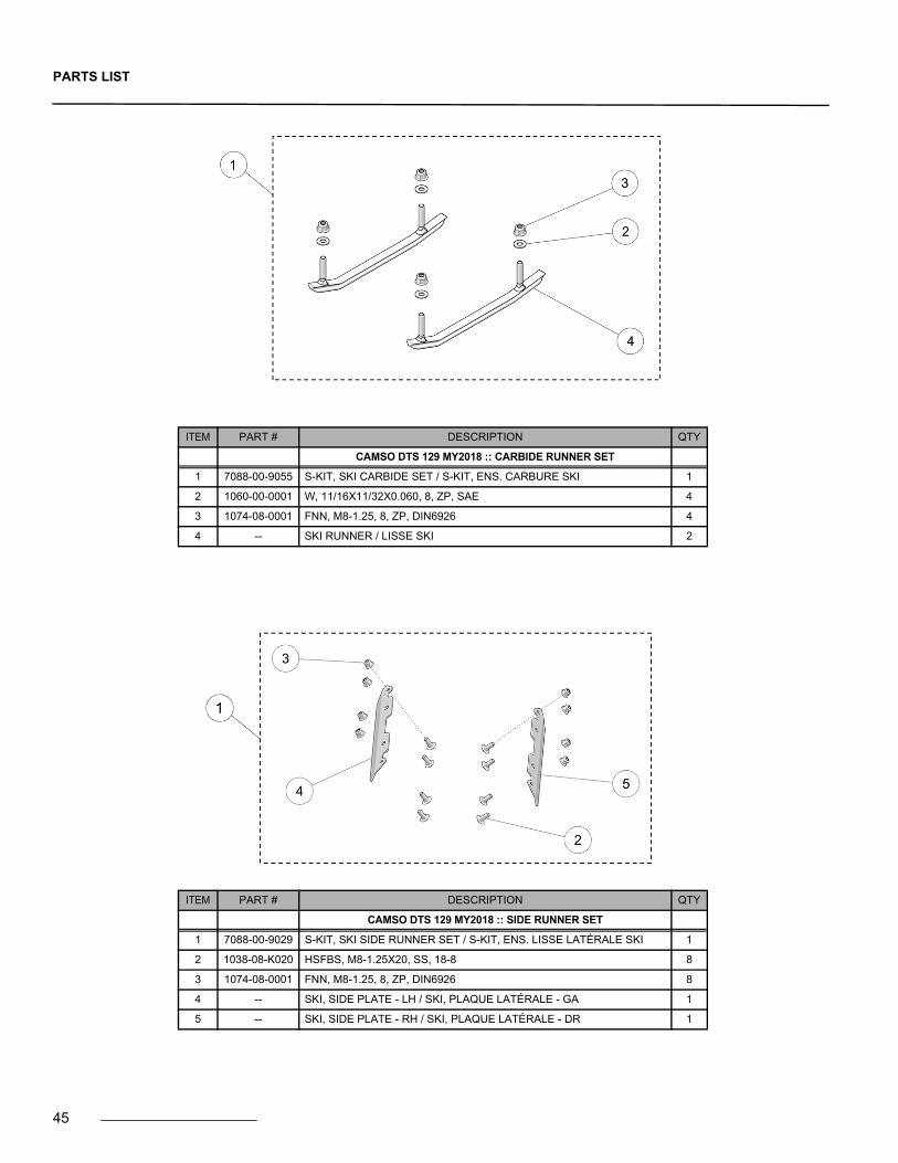
ITEM PART # DESCRIPTION QTY
CAMSO DTS 129 MY2018 :: CARBIDE RUNNER SET
1 7088-00-9055 S-KIT, SKI CARBIDE SET / S-KIT, ENS. CARBURE SKI 1
2 1060-00-0001 W, 11/16X11/32X0.060, 8, ZP, SAE 4
3 1074-08-0001 FNN, M8-1.25, 8, ZP, DIN6926 4
4 -- SKI RUNNER / LISSE SKI 2
ITEM PART # DESCRIPTION QTY
CAMSO DTS 129 MY2018 :: SIDE RUNNER SET
1 7088-00-9029 S-KIT, SKI SIDE RUNNER SET / S-KIT, ENS. LISSE LATÉRALE SKI 1
2 1038-08-K020 HSFBS, M8-1.25X20, SS, 18-8 8
3 1074-08-0001 FNN, M8-1.25, 8, ZP, DIN6926 8
4 -- SKI, SIDE PLATE - LH / SKI, PLAQUE LATÉRALE - GA 1
5 -- SKI, SIDE PLATE - RH / SKI, PLAQUE LATÉRALE - DR 1
45

PARTS LIST
ITEM PART # DESCRIPTION QTY
CAMSO DTS 129 MY2018 :: SKI RUBBER DAMPER
1 7093-00-0215 S-KIT, SKI RUBBER / S-KIT, CAOUTCHOUC SKI 1
2 -- SKI, DAMPER / SKI, AMORTISSEUR 1
3 1096-00-0001 PN, 20X10X2, 2 1
p
ITEM PART # DESCRIPTION QTY
CAMSO DTS 129 MY2018 :: FRAME FASTENERS
1 7000-00-9001 S-KIT, FASTENERS, DTS FRAME / BOULONNERIE, DTS FRAME 1
46

PARTS LIST
47
ITEM PART # DESCRIPTION QTY
CAMSO DTS 129 MY2018 :: SUSPENSION FASTENERS
1 7000-00-9003 S-KIT, FASTENERS / BOULONNERIE - DTS SUSPENSION 1
ITEM PART # DESCRIPTION QTY
CAMSO DTS 129 MY2018 :: SUSPENSION LIMITER CABLE
1 7003-00-9002 S-KIT, SUSPENSION LIMITER CABLE / S-KIT, CÂBLE LIMITEUR, SUSP. 1
2 -- CABLE / CÂBLE 2
3 1032-04-J010 SHCS, M4-0.7X10, 12.9, ZP, DIN912 4
4 -- CABLE SLEEVE / MANCHON DE CÂBLE 2

PARTS LIST
ITEM PART # DESCRIPTION QTY
CAMSO DTS 129 MY2018 :: WHEEL KIT
1 7200-00-9050 SKI, WHEEL KIT / ENSEMBLE DE ROUE, SKI 1
2 1016-00-2260 WHEEL (4.10/3.50-6) BLACK - ASS'Y / ROUE (4.10/3.50-6) NOIR - ASS. 2
3 1016-00-9200 WHEEL, 200 MM / ROUE, 200 MM 2
4 1017-00-0042 WHEEL CAP / CAPUCHON DE ROUE 2
5 1033-06-0020 BOLT / BOULON - HCS, M6-1X20, 8.8, ZP, DIN933 1
6 1033-10-2026 BOLT / BOULON - HCSW, M10-1.5X25, 8.8, ZP, TL, DIN933 2
7 1036-08-0025 BOLT / BOULON - HFSCS, M8-1.25X25, 8.8, ZP, DIN6921 2
8 1060-08-0001 WASHER / RONDELLE - W, 24X8.4X2, ZP, DIN9021 2
9 1071-06-0001 NYLON NUT / ÉCROU NYLON - NN, M6-1, ZP, DIN982 1
10 -- RETAINING CHAIN / CHAINE DE RETENUE 1
11 -- REAR SHAFT / ARBRE ARRIÈRE 1
12 -- WHEEL KIT WELDMENT / ENSEMBLE ROUE SOUDAGE 1
48