Embed Size (px)
Citation preview

CAMPUS WIDE OVERHEAD PAGING SYSTEM
REPLACEMENT PROJECT
FOR
JAMES A. HALEY VETERANS HOSPITAL
TAMPA, FLORIDA
SPECIFICATIONS
for
DEPARTMENT OF VETERANS AFFAIRS
VA Project Number 673-09-605
BID SET
August 18, 2010
115 East Forsyth St. • Jacksonville, Florida 32202 USA • (904)798-8333 • Fax (904)798-8335
www.ttvarch.com • Lic.#AA0002609 • [email protected]


Table of Contents,
Section 00 01 10 - Page 1
CAMPUS WIDE OVERHEAD PAGING SYSTEM REPLACEMENT PROJECT
JAMES A. HALEY VETERANS’ HOSPITAL
100% SUBMITTAL
TABLE OF CONTENTS
Section 00 01 10
Page #
DIVISION 0 - SPECIAL SECTIONS
00 01 15 List of Drawing Sheets
DIVISION 1 - GENERAL REQUIREMENTS
01 00 00 General Requirements
01 00 45 Cutting and Patching
01 32 16 Project Schedules
01 33 23 Shop Drawings, Product Data, and Samples
01 42 19 Reference Standards
01 45 29 Testing Laboratory Services
01 57 19 Temporary Environmental Controls
01 58 16 Temporary Interior Signage
01 74 19 Construction Waste Management
01 91 00 General Commissioning Requirements
DIVISION 2 – EXISTING CONDITIONS
02 41 00 Demolition
02 82 11 Traditional Asbestos Abatement
02 82 13.19 Asbestos Floor Tile and Mastic Abatement
DIVISION 3 – CONCRETE
Not Used
DIVISION 4 – MASONRY
Not Used
DIVISION 5 – METALS
Not Used
DIVISION 6 - WOOD AND PLASTIC
Not Used
DIVISION 7 - THERMAL AND MOISTURE PROTECTION
07 81 00 Applied Fireproofing
07 84 00 Fire stopping
DIVISION 8 - DOORS AND WINDOWS

Table of Contents,
Section 00 01 10 - Page 2
Not Used
DIVISION 9 – FINISHES
09 22 16 Non-Structural Metal Framing
09 29 00 Gypsum Board
09 91 00 Painting
DIVISION 10 – SPECIALTIES
Not Used
DIVISION 11 – EQUIPMENT
Not Used
DIVISION 12 – FURNISHINGS
Not Used
DIVISION 13 - SPECIAL CONSTRUCTION
Not Used
DIVISION 14– CONVEYING EQUIPEMENT
Not Used
DIVISION 21- FIRE SUPPRESSION
Not Used
DIVISION 22 – PLUMBING
Not Used
DIVISION 23 – HEATING, VENTILATING, AND AIR
CONDITIONING
Not Used
DIVISION 26 – ELECTRICAL
26 05 11 Requirements for Electrical Installations
26 05 21 Low-Voltage Electrical Power Conductors and Cables
(600 Volts and Below)
26 05 26 Grounding and Bonding for Electrical Systems
26 05 33 Raceway and Boxes for Electrical Systems
26 05 41 Underground Electrical Construction
26 27 26 Wiring Devices

Table of Contents,
Section 00 01 10 - Page 3
DIVISION 27 – COMMUNICATIONS
27 08 00 Commissioning of Communications Systems
27 05 11 Requirement for Communications
27 10 00 Structured Cabling
27 51 16 Public Address and Mass Installations
DIVISION 28 – ELECTRONIC SAFETY AND SECURITY
Not Used
DIVISION 31 – EARTHWORK
Not Used
DIVISION 32 – EXTERIOR IMPROVEMENTS
Not Used
DIVISION 33 – UTILITIES
Not Used
DIVISION 34 – TRANSPORTATION
Not Used

THIS PAGE INTENTIONALLY LEFT BLANK

CAMPUS WIDE OVERHEAD PAGING SYSTEM REPLACEMENT
JAMES A. HALEY VETERANS’ HOSPITAL
List of Drawing Sheets,
Section 00 01 15 - Page 1
SECTION 00 01 15
LIST OF DRAWING SHEETS
The drawings listed below accompanying this specification form a part of the
contract.
Drawing No. Title
GENERAL
GI001 Cover Sheet
GI002 Legend, Abbreviations, Code Summary, and General Notes
ASBESTOS
AA101 Asbestos Abatement Plans
PAGING
PA001 Paging System Legend, Notes, and Details
PA002 Paging System Site Plan
PA101 Building #1 Basement Wing “A” Partial Floor Plan – Paging
System
PA102 Building #1 Basement Wing “B” Partial Floor Plan – Paging
System
PA103 Building #1 Basement Wing “C” Partial Floor Plan – Paging
System
PA104 Building #1 Basement Wing “D” Partial Floor Plan – Paging
System
PA105 Building #1 Ground Floor Wing “A” Partial Floor Plan –
Paging System
PA106 Building #1 Ground Floor Wing “B” Partial Floor Plan –
Paging System
PA107 Building #1 Ground Floor Wing “C” Partial Floor Plan –
Paging System
PA108 Building #1 Ground Floor Wing “D” Partial Floor Plan –
Paging System
PA109 Building #1 First Floor Wing “A” Partial Floor Plan –
Paging System
PA110 Building #1 First Floor Wing “B” Partial Floor Plan –
Paging System
PA111 Building #1 First Floor Wing “C” Partial Floor Plan –
Paging System
PA112 Building #1 First Floor Wing “D” Partial Floor Plan –
Paging System
PA113 Building #1 Second Floor Wing “A” Partial Floor Plan –
Paging System
PA114 Building #1 Second Floor Wing “B” Partial Floor Plan –
Paging System

CAMPUS WIDE OVERHEAD PAGING SYSTEM REPLACEMENT
JAMES A. HALEY VETERANS’ HOSPITAL
List of Drawing Sheets,
Section 00 01 15 - Page 2
PA115 Building #1 Second Floor Wing “C” Partial Floor Plan –
Paging System
PA116 Building #1 Second Floor Wing “D” Partial Floor Plan –
Paging System
PA117 Building #1 Third Floor Plan – Paging System
PA118 Building #1 Fourth Floor Plan – Paging System
PA119 Building #1 Fifth Floor Plan – Paging System
PA120 Building #1 Sixth Floor Plan – Paging System
PA121 Building #1 Seventh Floor and Penthouse Floor Plans –
Paging System
PA122 Building #2 Ground and Basement Floor Plans – Paging
System
PA123 Building #2 First and Second Floor Plan – Paging System
PA124 Building #4, 19, and 36 Floor Plans – Paging System
PA125 Building #30 Ground Floor Plan – Paging System
PA126 Building #30 First Floor Plan – Paging System
PA127 Building #30 Second Floor Plan – Paging System
PA128 Building #30 Third Floor Plan – Paging System
PA129 Building #32 Basement Floor Plan – Paging System
PA130 Building #32 Ground Floor Plan – Paging System
PA131 Building #32 First Floor Plan – Paging System
PA132 Building #38 Basement Floor Plan – Paging System
PA133 Building #38 Partial First Floor Plan – Paging System
PA134 Building #38 Partial First Floor Plan – Paging System
PA135 Building #39 First and Second Floor Plans – Paging System
PA136 Building #41 Floor Plans – Paging System
PA137 Building #42 Partial First and Second Floor Plans –
Paging System
PA138 Building #54 and #56 Floor Plans – Paging System
PA139 Building #68 Floor Plans – Paging System
PA140 Building #T33 and #T72 Floor Plans – Paging System
PA141 Building #T57 – T71 Floor Plans – Paging System
PA142 Building #T73, T74, T75, and T76 Floor Plans – Paging
System
PA143 Paging System Riser Diagrams
PA144 Paging System Riser Diagrams
PA145 Paging System Riser Diagrams
PA146 Paging System Riser Diagrams
PA147 Paging System Riser Diagrams
- - - E N D - - -

CAMPUS WIDE OVERHEAD PAGING SYSTEM REPLACEMENT
JAMES A. HALEY VETERANS’ HOSPITAL
General Requirements, Revised Oct. 2009
Section 01 00 00 – Page i
SECTION 01 00 00
GENERAL REQUIREMENTS
PROJECT NUMBER: 673-09-605 CAMPUS WIDE OVERHEAD PAGING SYSTEM REPLACEMENT
TABLE OF CONTENTS
1.1 GENERAL INTENTION....................................................... 1
1.2 STATEMENT OF BID ITEM(S)................................................ 3
1.3 SPECIFICATIONS AND DRAWINGS FOR CONTRACTOR.............................. 3
1.4 CONSTRUCTION SECURITY REQUIREMENTS...................................... 3
1.5 FIRE SAFETY............................................................. 6
1.6 OPERATIONS AND STORAGE AREAS........................................... 10
1.7 ALTERATIONS............................................................ 19
1.8 INFECTION PREVENTION MEASURES.......................................... 21
1.9 DISPOSAL AND RETENTION................................................. 24
1.10 PROTECTION OF EXISTING VEGETATION, STRUCTURES, EQUIPMENT, UTILITIES, AND
IMPROVEMENTS .......................................................... 26
1.11 RESTORATION........................................................... 28
1.12 PHYSICAL DATA......................................................... 28
1.13 PROFESSIONAL SURVEYING SERVICES....................................... 29
1.14 LAYOUT OF WORK........................................................ 29
1.15 AS-BUILT DRAWINGS..................................................... 30
1.16 USE OF ROADWAYS, PARKING LOTS, AND GROUNDS............................ 31
1.17 COTR and CONTRACING OFFICER'S FIELD OFFICES........................... 32
1.18 TEMPORARY USE OF MECHANICAL AND ELECTRICAL EQUIPMENT.................. 32
1.19 TEMPORARY USE OF EXISTING ELEVATORS................................... 33
1.20 TEMPORARY TOILETS..................................................... 34
1.21 AVAILABILITY AND USE OF UTILITY SERVICES.............................. 35
1.22 NEW TELEPHONE EQUIPMENT............................................... 37
1.23 TESTS / COMMISSIONING................................................. 37
1.24 INSTRUCTIONS.......................................................... 38
1.25 GOVERNMENT-FURNISHED PROPERTY......................................... 39
1.26 RELOCATED EQUIPMENT AND ITEMS ........................................ 40
1.27 STORAGE SPACE FOR DEPARTMENT OF VETERANS AFFAIRS EQUIPMENT............ 41
1.28 CONSTRUCTION SIGN..................................................... 41
1.29 SAFETY SIGN........................................................... 42
1.30 CONSTRUCTION DIGITAL IMAGES........................................... 42
1.31 FINAL ELEVATION DIGITAL IMAGES........................................ 44
1.32 HISTORIC PRESERVATION................................................. 44
1.33 EQUIPMENT............................................................. 43
1.34 FINAL PAYMENT......................................................... 43
1.35 WARRANTY CALLS........................................................ 43
1.36 ATTACHMENTS........................................................... 43

CAMPUS WIDE OVERHEAD PAGING SYSTEM REPLACEMENT
JAMES A. HALEY VETERANS’ HOSPITAL
General Requirements, Revised Oct. 2009
Section 01 00 00 – Page 1
PROJECT DESCRIPTION
The Campus Wide Overhead Paging System Replacement Project at the James A.
Haley Veterans Hospital in Tampa, Florida, is a project that will
include providing a complete paging system upgrade for the entire
existing Medical Campus including all buildings & trailers. The work
will occur in fully occupied areas, in one phase, and includes but is
not limited to demolition, electrical, patch & repair work, and minor
asbestos abatement. Refer to drawings for specific work.
1.1 GENERAL INTENTION
A. Contractor shall completely prepare site for building operations,
including demolition and other items as indicated herein. The
Contractor shall furnish all necessary equipment, labor, materials,
temporary equipment and items, tools, specialty services, supervision,
and perform work for NRM Project No. 673-09-605, “Campus Wide Overhead
Paging System Replacement Project” at the James A. Haley Veterans
Hospital located in Tampa, Florida as required by drawings and
specifications.
B. Visits to the site by Bidders are highly recommended and may be made
only by appointment with the Project Manager/Contracting Officer’s
Technical Representative (COTR), Marty Brothers at telephone number
(813) 972-2000 extension 2140. All bids will take into consideration of
existing site conditions; it is the responsibility of the contractor to
review the entire job site footprint and existing site conditions prior
to bid submission. All proposals shall include a detailed cost breakdown
(materials, labor, and equipment) by trade, specification division and
section; lump sum costs are not acceptable.
C. Offices of TTV Architecs, as Architect-Engineers (AE, A/E), will render
certain technical services during construction. Such services shall be
considered as advisory to the Government and shall not be construed as
expressing or implying a contractual act of the Government without
affirmations by Contracting Officer or his duly authorized
representative.
D. Before placement and installation of work subject to tests by testing
laboratory or other parties retained by Department of Veterans Affairs,
the Contractor shall notify the COTR and Contracting Officer (CO) in

CAMPUS WIDE OVERHEAD PAGING SYSTEM REPLACEMENT
JAMES A. HALEY VETERANS’ HOSPITAL
General Requirements, Revised Oct. 2009
Section 01 00 00 – Page 2
sufficient time to enable testing laboratory personnel to be present at
the site in time for proper taking and testing of specimens and field
inspection. Such prior notice shall be not less than seven (7) calendar
days, unless otherwise designated by the COTR and Contracting Officer.
E. All employees of general contractor and subcontractors shall comply
with VA security management program and obtain permission of the VA
Police, be identified by project and employer, and restricted from
unauthorized access.
F. Prior to commencing work, general contractor shall provide proof that
an OSHA certified “competent person” (CP) [(29 CFR 1926.20(b)(2)] will
maintain a presence at the work site whenever the general or
subcontractors are present.
G. Training:
1. Beginning July 31, 2005, all supervisory type personnel and
employees of general contractor and subcontractors shall have the
30-hour OSHA certified Construction Safety course and other relevant
competency training, as determined by VA CP with input from the ICRA
team.
2. Beginning July 31, 2005, all non-supervisory type personnel and
employees of general contractor and subcontractors shall have the
10-hour OSHA certified Construction Safety Course and other relevant
competency training, as determined by VA CP with input from the ICRA
team.
3. Submit copies of certificates and training records for all such
personnel and employees that may be and/or will be on the work
site(s) to the COTR and Contracting Officer for approval before the
start of any work on-site.
H. Related Work: This specification section applies to ALL Divisions (0
through 34) of work under ALL other specification sections. A
partial list of Codes and Standards adopted by the Department of
Veterans Affairs is attached in Appendix B.
I. Normal Operation / Construction Hours: Construction operations at the
James A. Haley VA Hospital are 7:30 AM to 4:30 PM, Monday through
Friday, with the exception of Federal Holidays. Requests to work
beyond normal work hours shall be submitted in writing to the Resident
Engineer / COTR for approval and will include a description of work to
be performed. Approval is subject to availability of the Resident

CAMPUS WIDE OVERHEAD PAGING SYSTEM REPLACEMENT
JAMES A. HALEY VETERANS’ HOSPITAL
General Requirements, Revised Oct. 2009
Section 01 00 00 – Page 3
Engineer / COTR, type of work to be performed, and the specific hours
requested. Contractors are reminded that patients are generally asleep
after 10:00 PM. Approval to work beyond this time will also include an
evaluation of the anticipated noise level generated by the contractor.
Under no circumstances will the contractor proceed without express,
written approval of the Resident Engineer / COTR.
1.2 STATEMENT OF BID ITEM(S)
A. ITEM I, GENERAL CONSTRUCTION: Provide all necessary equipment, labor,
materials, specialty services, supervision, and tools to complete NRM
Project No. 673-09-605, “Campus Wide Overhead Paging System Replacement
Project”. Work includes architectural, asbestos abatement, electrical,
and certain other items of work required by the drawings and
specifications. All work is to be completed in the number of calendar
days (including any weekend work and night shift work) as specified by
the VA Contracting Officer during the Pre-Bid Conference.
1.3 SPECIFICATIONS AND DRAWINGS FOR CONTRACTOR
A. Additional sets of drawings and specifications may be made by the
Contractor, at Contractor's expense, from PDF document copies that can
be requested from the COTR’s electronic files.
B. Additional sets of drawings and specifications may be made by the
Contractor, at Contractor's expense, from electronic or reproducible
hard copy prints furnished by the ISSUING OFFICE. Such media or prints
shall be returned to the ISSUING OFFICE immediately after printing is
completed.
1.4 CONSTRUCTION SECURITY REQUIREMENTS
A. Security Plan:
1. The security plan defines both physical and administrative security
procedures that will remain effective for the entire duration of the
project.
2. The General Contractor is responsible for assuring that all sub-
contractors working on the project and their employees also comply
with these regulations.
3. The General Contractor shall furnish to the COTR and Contracting
Officer lists of employees that will be or may be on the
construction site(s). The List shall be on Company letter head that
provides all of the company contact information, shall provide the
project number and title, locations of work, names of the employees,

CAMPUS WIDE OVERHEAD PAGING SYSTEM REPLACEMENT
JAMES A. HALEY VETERANS’ HOSPITAL
General Requirements, Revised Oct. 2009
Section 01 00 00 – Page 4
their titles, their job types, and personal contact numbers (i.e.
cell phone). All sub-contractors, vendors and suppliers for the
project shall furnish the same listing on their individual company
letter heads to the GC whom will provide the lists to the COTR and
Contracting Officer. These lists shall be updated as necessary
during the entire duration of the project. These lists may be used
to provide a check list record of personnel on-site each day to be
provided with the contractors Daily Log reports. These lists may be
used to provide a check list record of personnel on-site each day to
be provided to the VA Police Department and their Dispatch Office
where normal sign in and sign out occurs.
B. Security Procedures:
1. General Contractor’s employees shall not enter the project site
without appropriate badge. They may also be subject to inspection
of their personal effects when entering or leaving the project site.
2. For working outside the “regular hours” as defined in the contract,
The General Contractor shall provide a request for approval 14
calendar days prior to the requested date, to the Contracting
Officer and COTR, so that security, escort and other appropriate
arrangements can be provided for the employees. This notice is
separate from any notices required for utility shutdown described
later in this section.
3. No photography of VA premises is allowed without written permission
of the Contracting Officer.
4. VA reserves the right to close down or shut down the project site
and order General Contractor’s employees off the premises in the
event of a national emergency. The General Contractor may return to
the site only with the written approval of the Contracting Officer.
C. Guards:
1. The General Contractor shall not be required to provide unarmed
guards at the project site twenty-four (24) hours a day, seven (7)
days a week or after construction hours.
2. Any guard provided (if required by project) shall have communication
devices to report events as directed by VA Police.

CAMPUS WIDE OVERHEAD PAGING SYSTEM REPLACEMENT
JAMES A. HALEY VETERANS’ HOSPITAL
General Requirements, Revised Oct. 2009
Section 01 00 00 – Page 5
3. The General Contractor is not required to install equipment for
recording guard rounds to ensure systematic checking of the
premises.
4. The General Contractor may need to provide a guard as required by
the contract drawings and specifications, including specification
sections for Asbestos Abatement.
D. Key Control:
1. The General Contractor shall provide duplicate keys and lock
combinations to the COTR and Contracting Officer for the purpose of
security inspections of every area of project including tool boxes
and parked machines and take any emergency action.
2. The General Contractor shall turn over lock cylinders to the VA COTR
and locksmith for permanent installation. See Section 08 71 00, DOOR
HARDWARE and coordinate.
3. Contractor may be issued keys for construction through the COTR and
Contracting Officer.
4. All keys must be turned in at the end of Contract.
5. Any key assigned to the contractor, which is lost or stolen will
result in a replacement cost of $100.00 per key either lost or stolen.
Any key either lost or stolen shall be reported to the COTR; it is the
contractor’s responsibility to inform VA Police and give a detailed
report about the key loss. The contractor shall take a copy of the
official police report and make payment to the Agent Cashier before
any additional replacement keys are made. Final payment may be
withheld and or reduced until all keys are returned or accounted for.
A copy of the Police Report and receipt of payment shall be provided
to the VA COTR.
E. Document Control:
1. Before starting any work, the General Contractor/Sub Contractors
shall submit an electronic security memorandum describing the
approach to following goals and maintaining confidentiality of
“sensitive information”.
2. The General Contractor is responsible for safekeeping of all
drawings, project manual and other project information. This
information shall be shared only with those with a specific need to
accomplish the project.

CAMPUS WIDE OVERHEAD PAGING SYSTEM REPLACEMENT
JAMES A. HALEY VETERANS’ HOSPITAL
General Requirements, Revised Oct. 2009
Section 01 00 00 – Page 6
3. Certain documents, sketches, videos or photographs and drawings may
be marked “Law Enforcement Sensitive” or “Sensitive Unclassified”.
Secure such information in separate containers and limit the access
to only those who will need it for the project. Return the
information to the Contracting Officer upon request.
4. These security documents shall not be removed or transmitted from
the project site without the written approval of Contracting
Officer.
5. All paper waste or electronic media such as CD’s and diskettes shall
be shredded and destroyed in a manner acceptable to the VA.
6. Notify Contracting Officer and Site Security Officer immediately
when there is a loss or compromise of “sensitive information”.
7. All electronic information shall be stored in specified location
following VA standards and procedures using an Engineering Document
Management Software (EDMS).
a. Security, access and maintenance of all project drawings, both
scanned and electronic shall be performed and tracked through the
EDMS system.
b. “Sensitive information” including drawings and other documents
may be attached to e-mail provided all VA encryption procedures
are followed.
F. Motor Vehicle Restrictions
1. Vehicle authorization request shall be required for any vehicle
entering the site and such request shall be submitted at least
twenty-four (24) hours before the date and time of access. Access
shall be restricted to picking up and dropping off materials and
supplies.
2. Separate permits shall be issued for General Contractor and its
employees for parking in designated areas only.
3. There are no Contractor designated general parking areas. General
Contractor parking is at the University Mall. The Patient Shuttle
Services provided by the VA can be used on a first come, first
served basis.
1.5 FIRE SAFETY
A. Applicable Publications: Publications listed below form part of this
Article to extent referenced. Publications are referenced in text by
basic designations only.

CAMPUS WIDE OVERHEAD PAGING SYSTEM REPLACEMENT
JAMES A. HALEY VETERANS’ HOSPITAL
General Requirements, Revised Oct. 2009
Section 01 00 00 – Page 7
1. American Society for Testing and Materials (ASTM):
E84-2008.............Surface Burning Characteristics of Building
Materials
2. National Fire Protection Association (NFPA):
10-2006..............Standard for Portable Fire Extinguishers
30-2007..............Flammable and Combustible Liquids Code
51B-2003.............Standard for Fire Prevention During Welding,
Cutting and Other Hot Work
70-2007..............National Electrical Code
241-2004.............Standard for Safeguarding Construction,
Alteration, and Demolition Operations
3. Occupational Safety and Health Administration (OSHA):
29 CFR 1926..........Safety and Health Regulations for Construction
4. Hospital Policy Memorandums:
HPM 138-03...........Safety and Health during Construction
Activities
HPM 138-04...........Lockout / Tagout Program
HPM 138-15...........Interim Life Safety Measures (ILSM)
HPM 138-17...........Notification of Fire Alarm Shutdown
HPM 138-23...........Utility Shutdown Procedures
HPM 138-24...........Infection Control during Construction and
Renovation
B. Fire Safety Plan: Establish and maintain a fire protection program in
accordance with 29 CFR 1926. Prior to start of work, prepare a plan
detailing project-specific fire safety measures, including periodic
status reports, and submit to COTR and Contracting Officer for review
for compliance with contract requirements in accordance with Section 01
33 23, SHOP DRAWINGS, PRODUCT DATA AND SAMPLES. Prior to any worker
for the contractor or subcontractors beginning work, they shall undergo
a safety briefing provided by the general contractor’s competent person
per OSHA requirements. This briefing shall include information on the
construction limits, VAMC safety guidelines, means of egress, break
areas, work hours, locations of restrooms, use of VAMC equipment, etc.
Documentation shall be provided to the COTR and Contracting Officer
that individuals have undergone contractor’s safety briefing.

CAMPUS WIDE OVERHEAD PAGING SYSTEM REPLACEMENT
JAMES A. HALEY VETERANS’ HOSPITAL
General Requirements, Revised Oct. 2009
Section 01 00 00 – Page 8
C. Site and Building Access: Maintain free and unobstructed access to
facility emergency services and for fire, police and other emergency
response forces in accordance with NFPA 241.
D. Temporary Facilities: Separate temporary facilities, such as trailers,
storage sheds, and dumpsters, from existing buildings and new
construction by distances in accordance with NFPA 241. For small
facilities with less than 6.1 m (20 feet) exposing overall length,
separate by 3.0 m (10 feet).
E. Temporary Construction Partitions:
1. Install and maintain temporary construction partitions to provide
smoke-tight separations between, construction areas, the areas that
are described in phasing requirements, and adjoining areas.
Construct partitions of gypsum board or treated plywood (flame
spread rating of 25 or less in accordance with ASTM E84) on both
sides of fire retardant treated wood or metal steel studs. Extend
the partitions through suspended ceilings to floor slab deck or
roof. Seal joints and penetrations. At door openings, install Class
C, ¾ hour fire/smoke rated doors with self-closing devices.
2. Install one-hour and/or two-hour fire-rated temporary construction
partitions as shown on drawings and/or as indicated in the
specification sections to maintain integrity of existing exit stair
enclosures, exit passageways, fire-rated enclosures of hazardous
areas, horizontal exits, smoke barriers, vertical shafts and
openings enclosures.
3. Close openings in smoke barriers and fire-rated construction to
maintain fire ratings. Seal penetrations with listed through-
penetration fire stop materials in accordance with Section 07 84 00,
FIRESTOPPING.
F. Temporary Heating and Electrical: Install, use and maintain
installations in accordance with 29 CFR 1926, NFPA 241 and NFPA 70.
G. Means of Egress: Do not block exiting for occupied buildings, including
paths from exits to roads. Minimize disruptions and coordinate with
COTR and Contracting Officer.
H. Egress Routes for Construction Workers: Maintain free and unobstructed
egress. Inspect daily. Report findings and corrective actions weekly to
the COTR and Contracting Officer.

CAMPUS WIDE OVERHEAD PAGING SYSTEM REPLACEMENT
JAMES A. HALEY VETERANS’ HOSPITAL
General Requirements, Revised Oct. 2009
Section 01 00 00 – Page 9
I. Fire Extinguishers: Provide and maintain extinguishers in construction
areas and temporary storage areas in accordance with 29 CFR 1926, NFPA
241 and NFPA 10.
J. Flammable and Combustible Liquids: Store, dispense and use liquids in
accordance with 29 CFR 1926, NFPA 241 and NFPA 30.
K. Standpipes: Install and extend standpipes up with each floor in
accordance with 29 CFR 1926 and NFPA 241. Do not charge wet standpipes
subject to freezing until weather protected.
L. Sprinklers: Install, test and activate new automatic sprinklers prior
to removing existing sprinklers.
M. Existing Fire Protection: Do not impair automatic sprinklers, smoke and
heat detection, and fire alarm systems, except for portions immediately
under construction, and temporarily for connections. GC to provide fire
watch for impairments more than four (4) hours in a twenty-four (24)
hour period, regardless of athe time of day. Request interruptions in
accordance with Article 1.6, OPERATIONS AND STORAGE AREAS, and
coordinate with COTR and Contracting Officer. All existing or temporary
fire protection systems (fire alarms, sprinklers) located in
construction areas shall be tested as coordinated with the medical
center. Parameters for the testing and results of any tests performed
shall be recorded by the medical center and copies provided to the COTR
and Contracting Officer.
N. Smoke Detectors: Prevent accidental operation. Remove temporary covers
at end of work operations each day. Coordinate with COTR and
Contracting Officer. Replace all smoke detection devices in the
construction area with heat detection devices for the duration of the
project. Prior to final project inspection, smoke detectors shall be
reinstalled.
O. Hot Work (Burn Permit): Perform and safeguard hot work operations in
accordance with NFPA 241 and NFPA 51B. Coordinate with COTR and
Contracting Officer. Obtain permits from facility COTR and Contracting
Officer at least seventy-two (72) hours in advance. Designate
contractor's responsible project-site fire prevention program manager
to permit hot work. See Appendix C for the proper procedure and forms
for hot work.
P. Fire Hazard Prevention and Safety Inspections: Inspect entire
construction areas daily. Coordinate with, and report findings and

CAMPUS WIDE OVERHEAD PAGING SYSTEM REPLACEMENT
JAMES A. HALEY VETERANS’ HOSPITAL
General Requirements, Revised Oct. 2009
Section 01 00 00 – Page 10
corrective actions daily to COTR and Contracting Officer. See HPM 138-
03.
Q. Smoking: Smoking is prohibited in and adjacent to construction areas
inside and outside of existing buildings and additions under
construction. In separate and detached buildings under construction,
smoking is prohibited, except in designated smoking rest areas.
R. Waste: Dispose of waste and debris in accordance with NFPA 241. Remove
from buildings and site daily.
S. Construction Operations: Perform other construction, alteration and
demolition operations in accordance with 29 CFR 1926.
T. Impaired Areas: If required, submit documentation to the COTR and
Contracting Officer that personnel have been trained in the fire safety
aspects of working in areas with impaired structural or
compartmentalization features.
U. Forms: Forms for certain Fire Safety items are attached to this
specification section.
1.6 OPERATIONS AND STORAGE AREAS
A. The Contractor shall confine all operations (including storage of
materials) on Government premises to areas authorized or approved by
the COTR and the Contracting Officer. The Contractor shall hold and
save the Government, its officers and agents, free and harmless from
liability of any nature occasioned by the Contractor's performance.
B. Temporary buildings (e.g., storage sheds, shops, offices) and utilities
may be erected by the Contractor only with the approval of the COTR and
the Contracting Officer and shall be built with labor and materials
furnished by the Contractor without expense to the Government. The
temporary buildings and utilities shall remain the property of the
Contractor and shall be removed by the Contractor at its expense upon
completion of the work. With the written consent of the COTR and the
Contracting Officer, the buildings and utilities may be abandoned and
need not be removed.
C. The Contractor shall, under regulations prescribed by the COTR and the
Contracting Officer, use only established roadways, or use temporary
roadways constructed by the Contractor when and as authorized by the
COTR and the Contracting Officer. When materials are transported in
prosecuting the work, vehicles shall not be loaded beyond the loading
capacity recommended by the manufacturer of the vehicle or prescribed

CAMPUS WIDE OVERHEAD PAGING SYSTEM REPLACEMENT
JAMES A. HALEY VETERANS’ HOSPITAL
General Requirements, Revised Oct. 2009
Section 01 00 00 – Page 11
by any Federal, State, or local law or regulation. When it is necessary
to cross curbs or sidewalks, the Contractor shall protect them from
damage. The Contractor shall repair or pay for the repair of any
damaged curbs, sidewalks, or roads.
D. Working space and space available for storing materials shall be as
determined by the COTR and Contracting Officer. The Contractor shall
keep ALL work areas, storage areas, staging areas, and access areas and
routes clean and neat. The Contractor shall provide sufficient trash
containers so there is no debris lying around. The containers shall be
emptied at the least daily and trash disposed of by the contractor.
E. Workmen are subject to rules of the Medical Center applicable to their
conduct. All personal automobiles and contractor vehicles shall be
parked off-site, as there is no available parking on-site.
F. Execute work in such a manner as to interfere as little as possible
with work being done by others. Keep roads clear of construction
materials, debris, standing construction equipment and vehicles at all
times.
G. Execute work so as to interfere as little as possible with normal
functioning of the Medical Center as a whole, including operations of
utility services, fire protection systems and any existing equipment,
and with work being done by others. Use of equipment and tools that
transmit vibrations and noises through the building structure, are not
permitted in buildings that are occupied, during construction, jointly
by patients or medical personnel, and Contractor's personnel, except as
permitted by COTR and Contracting Officer where required by limited
working space.
1. Do not store materials and equipment in other than assigned areas.
2. Schedule delivery of materials and equipment to immediate
construction working areas within buildings in use by Department of
Veterans Affairs in quantities sufficient for not more than two (2)
work days. Provide unobstructed access to the Medical Center areas
required to remain in operation.
3. Where access by the Medical Center personnel to vacated portions of
buildings is not required, storage of Contractor's materials and
equipment will be permitted subject to fire and safety requirements.
H. Utilities Services: Where necessary to cut existing pipes, electrical
wires, conduits, cables, etc., of utility services, or of fire

CAMPUS WIDE OVERHEAD PAGING SYSTEM REPLACEMENT
JAMES A. HALEY VETERANS’ HOSPITAL
General Requirements, Revised Oct. 2009
Section 01 00 00 – Page 12
protection systems or communications systems (except telephone), they
shall be cut and capped at suitable places where shown; or, in absence
of such indication, where directed by COTR and Contracting Officer. All
such actions shall be coordinated with the Utility Company involved:
1. Whenever it is required that a connection fee be paid to a public
utility provider for new permanent service to the construction
project, for such items as water, sewer, electricity, gas or steam,
payment of such fee shall be the responsibility of the Government
and not the Contractor.
I. Phasing: To insure such executions, Contractor shall furnish the COTR
and Contracting Officer with a schedule of approximate phasing dates on
which the Contractor intends to accomplish work in each specific area
of site, building or portion thereof. In addition, Contractor shall
notify the COTR and Contracting Officer twenty-one (21) calendar days
in advance of the proposed date of starting work in each specific area
of site, building or portion thereof. Arrange such phasing dates to
insure accomplishment of this work in successive phases mutually
agreeable to the Medical Center Director, COTR and Contracting Officer
and Contractor.
1. The contractor is to submit his phasing schedule in writing to the
Contracting Officer for review and approval no later than twenty-one
(21) calendar days after issuance of the Notice to Proceed. This
includes utility outages and access closures.
2. All work, such as corridor work, which is outside the main
construction area, shall be done on evenings or weekends, so as not
to disrupt the normal operations.
3. The contractor shall have all submittals completed and turned in to
the Government for review by the A/E firm no later than thirty (30)
calendar days from the date of the signed Notice to Proceed. The
government will return submittals within twenty-one (21) calendar
days from acceptance from the contractor. NO WORK SHALL BE STARTED
UNTIL ALL RELATED SUBMITTALS ARE APPROVED. All materials shall be
approved by the Government prior to delivery to the job site and
start of work.

CAMPUS WIDE OVERHEAD PAGING SYSTEM REPLACEMENT
JAMES A. HALEY VETERANS’ HOSPITAL
General Requirements, Revised Oct. 2009
Section 01 00 00 – Page 13
4. All renovation activities will take place at a busy Medical Center.
The contractor shall not interfere with existing, on-going functions,
or normal activity of the hospital. The contractor will provide walk-
off mats for dust control, appropriate construction barriers, and keep
noise & vibration to a minimum during normal business hours.
Contractors shall review Hospital Policy Memorandum (HPM) No. 138-24,
“Infection Control During Construction and Renovation” and comply as
outlined in this policy. Certain portions of the work will be
confined to evenings, and/or weekends, as identified on the drawings.
5. No work shall start until the preconstruction survey and inspection
is completed.
6. Contractor to completely abate the all floor tile and asbestos
mastic, and asbestos fireproofing and replace with non-asbestos
tile, mastic, and fireproofing as per Hospital Policy Memorandum No.
138-14 and per appropriate specification sections. The contractor
shall provide detailed abatement schedule.
7. Any utility service, parking lot, roadway, loading dock, and/or
Grounds interruptions requests shall be submitted in writing twenty-
one (21) calendar days in advance of the planned interruption. For
approval and coordination, see HPM 138-23.
8. Hot Work and other permits will be needed prior to the use of any
open flames, cutting operations, grinding operations and welding
operations. For approval and coordination, see Appendix C.
9. Set up phasing by buildings, wings, floors, or areas in accordance
with information received from the Medical Center through the COTR
and the Contracting Officer.
J. Occupied Buildings: Building(s) will be occupied during performance of
work.

CAMPUS WIDE OVERHEAD PAGING SYSTEM REPLACEMENT
JAMES A. HALEY VETERANS’ HOSPITAL
General Requirements, Revised Oct. 2009
Section 01 00 00 – Page 14
1. Contractor shall take all measures and provide all material
necessary for protecting existing equipment and property in affected
areas of construction against dust and debris, so that equipment and
affected areas to be used in the Medical Centers operations will not
be hindered. Contractor shall permit access to Department of
Veterans Affair’s personnel and patients through other construction
areas which serve as routes of access to such affected areas and
equipment. Coordinate alteration work in areas occupied by
Department of Veterans Affairs so that Medical Center operations
will continue during the construction period.
K. Buildings and Systems: When a building is turned over to Contractor,
Contractor shall accept entire responsibility therefore.
1. Contractor shall maintain a minimum temperature of 4 degrees C (40
degrees F) at all times, except as otherwise specified.
2. Contractor shall maintain in operating condition existing fire
protection and alarm equipment. In connection with fire alarm
equipment, Contractor shall make arrangements for pre-inspection of
site with Fire Department or Company (Department of Veterans Affairs
or municipal) whichever will be required to respond to an alarm from
Contractor's employee or watchman.
L. Existing Utilities Services: Maintain existing utility services for the
Medical Center at all times. Provide temporary facilities, labor,
materials, equipment, connections, and utilities to assure
uninterrupted services. Where necessary to cut existing water, steam,
gases, sewer or air pipes, or conduits, wires, cables, etc. of utility
services or of fire protection systems and communications systems
(including telephone), they shall be cut and capped at a main branch or
suitable places where shown; or, in absence of such indication, where
directed by the COTR and Contracting Officer.
1. No utility service such as water, gas, steam, sewers or electricity,
or fire protection systems and communications systems may be
interrupted without prior written approval of the COTR and
Contracting Officer. Electrical work shall be accomplished with all
affected circuits or equipment de-energized. When an electrical
outage cannot be accomplished, work on any energized circuits or
equipment shall not commence without the Medical Center Director’s
prior knowledge and written approval. Refer to specification

CAMPUS WIDE OVERHEAD PAGING SYSTEM REPLACEMENT
JAMES A. HALEY VETERANS’ HOSPITAL
General Requirements, Revised Oct. 2009
Section 01 00 00 – Page 15
Sections 26 05 11, REQUIREMENTS FOR ELECTRICAL INSTALLATIONS, 27 05
11 REQUIREMENTS FOR COMMUNICATIONS INSTALLATIONS, and 28 05 11,
REQUIREMENTS FOR ELECTRONIC SAFETY AND SECURITY INSTALLATIONS for
additional requirements. The attached Live Electrical Work
notification form must be used. See Appendix C for the proper forms
and procedures.
2. Contractor shall submit a request to interrupt any such services to
the COTR and Contracting Officer, in writing, twenty-one (21)
calendar days in advance of proposed interruption. Request shall
state reason, date, exact time of, and approximate duration of such
interruption. See Appendix C for the proper forms and procedures.
3. Contractor will be advised (in writing) of approval of request, or
of which other date and/or time such interruption will cause least
inconvenience to operations of the Medical Center. Interruption time
approved by Medical Center may occur at other than Contractor's
normal working hours.
4. Major interruptions of any system must be requested, in writing, at
least twenty-one (21) calendar days prior to the desired time and
shall be performed as directed by the COTR and Contracting Officer.
5. In case of a contract construction emergency, service will be
interrupted on approval of the COTR and Contracting Officer. Such
approval will be confirmed in writing as soon as practical. On the
next business day, the contractor’s Daily Log report shall explain
the circumstances causing the emergency and the corrective actions
taken.
6. Whenever it is required that a connection fee be paid to a public
utility provider for new permanent service to the construction
project, for such items as water, sewer, electricity, gas or steam,
payment of such fee shall be the responsibility of the Government
and not the Contractor.
M. Abandoned Lines: All service lines such as wires, cables, conduits,
ducts, pipes and the like, and their hangers or supports, which are to
be abandoned but are not required to be entirely removed, shall be
sealed, capped or plugged at the nearest main line or branch. The lines
shall not be capped in finished areas, but shall be removed and sealed,
capped or plugged in ceilings, within furred spaces, in unfinished
areas, or within walls or partitions; so that they are completely

CAMPUS WIDE OVERHEAD PAGING SYSTEM REPLACEMENT
JAMES A. HALEY VETERANS’ HOSPITAL
General Requirements, Revised Oct. 2009
Section 01 00 00 – Page 16
behind the finished surfaces unless otherwise directed by the COTR and
Contracting Officer.
N. Roads, Parking Lots, Docks and Grounds: To minimize interference of
construction activities with flow of Medical Center traffic, comply
with the following:
1. Keep roads, walks and entrances to grounds, to parking and to
occupied areas of buildings clear of construction materials, debris
and standing construction equipment and vehicles. Wherever
excavation for new utility lines cross existing roads, at least one
lane must be open to traffic at all times.
2. Method and scheduling of required cutting, altering and removal of
existing roads, parking lots, walks and entrances must be approved
by the COTR and Contracting Officer.
3. Interruptions of these areas must be requested, in writing, at least
twenty-one (21) calendar days prior to the desired time and shall be
performed as directed by the COTR and Contracting Officer.
4. Interruptions will follow the same procedures as outlined in Article
1.6.N.2, Existing Utility Services.
O. Coordination of Work: Coordinate the work for this contract with other
construction operations as directed by the COTR and Contracting
Officer. This includes the scheduling of traffic and the use of
roadways, as specified in Article 1.16, USE OF ROADWAYS, PARKING LOTS,
AND GROUNDS.
P. Coordination of Construction with Medical Center Director: The
activities at a Medical Center shall take precedence over construction
activities. The Contractor must cooperate and coordinate with the
Medical Center, through the COTR and Contracting Officer, in arranging
construction schedule to cause the least possible interference with
facility activities on the campus. Construction noise during the events
or services shall not disturb the events or service. Trucks and workmen
shall not pass through the event or service area during this period:
1. The Contractor is required to discontinue his work sufficiently in
advance of Easter Sunday, Mother's Day, Father's Day, Memorial Day,
Veteran's Day and/or Federal holidays, to permit him to clean up all
areas of operation adjacent to existing event or service areas
before these dates.

CAMPUS WIDE OVERHEAD PAGING SYSTEM REPLACEMENT
JAMES A. HALEY VETERANS’ HOSPITAL
General Requirements, Revised Oct. 2009
Section 01 00 00 – Page 17
2. The Medical Center observes the following Federal Holidays: New
Years Day, Labor Day, Martin Luther King Jr. Day, Columbus Day,
Presidents Day, Veterans Day, Memorial Day, Thanksgiving,
Independence Day, and Christmas Day.
3. Clean-up shall include the removal of all equipment, tools,
materials and debris and leaving the areas in a clean, neat
condition.
Q. SIGN-IN/OUT Procedures:
1. All contractor employees are required to sign in and out at VA Police
dispatch located in Building #1, First floor, A-Wing, Room 1A-147,
near the Emergency Room Entrance, unless otherwise directed by the
COTR. A valid state driver’s license or state identification card is
mandatory for all employees to have access to this facility. All
employees are required to wear the assigned VA badges at all times.
2. If after-hour key service is needed, contact the Hospital Police
Dispatch Office at extension 7554. All after hours work shall be
coordinated through the Contracting Officer in writing 14 calendar
days prior to approval.
R. REPORTS:
1. Daily Logs: In conjunction with the contractor's daily report,
Contractor shall furnish a daily report for each day from the date of
Notice to Proceed until Final Acceptance, including those days that no
work is performed. The report shall have attached there to a copy of
inspections conducted by the VA, a list of all employees on site that
day, however, this does not relieve the Contractor of the
responsibility to conduct and report inspections. Daily reports shall
be submitted on Form VAF 10-6131, "Daily Log” and hand delivered to
the COTR by 9:00 AM the following duty day.
2. Payrolls: Contractor shall submit two (2) copies of certified
payrolls required by VAAR 852.236-85 - Supplementary Labor Standard
Provision. Payrolls shall be submitted to the Contracting Officer no
later than Wednesday for the previous week.
3. Payment Requests: Monthly payment requests from the contractor will
not be processed unless all paperwork is current, including daily
reports, asbestos reports, and certified payrolls for the prime and
all subs.
4. Requests for Information and/or Clarification: All RFI’s and RFC’s

CAMPUS WIDE OVERHEAD PAGING SYSTEM REPLACEMENT
JAMES A. HALEY VETERANS’ HOSPITAL
General Requirements, Revised Oct. 2009
Section 01 00 00 – Page 18
shall be submitted to the Contracting Officer to ensure timely
response. The Government will answer RFI’s and RFC’s within twenty-
one (21) calendar days from acceptance from the contractor.
5. Submittal Log: The contractor shall utilize the specifications and
drawings to prepare and provide a submittal log. The Submittal Log
shall list all submittals by specification section, paragraph and
drawing numbers from the beginning to the end of the documents. The
Submittal Log shall be provided to the COTR and Contracting Officer
within ten (10) calendar days after receipt of Notice To Proceed. The
Government may require additional submittals at its discretion at no
additional cost. All submittals shall be approved, by the Contracting
Officer prior to beginning related work.
S. Material Safety Data Sheets (MSDS’s): Contractor shall provide five (5)
GREEN Loose-leaf binders, permanently labeled “MSDS Sheet for Project …”
with copies of each Material Safety Data Sheets for each and every
product, chemical, and other required materials to be used on this
project.
1. All instructions for use shall be compiled with.
2. Products will not be used until MSDS's are submitted to the COTR.
These shall be provided for any material no later than the day
before those materials arrive on VA property.
3. The contractor shall maintain a current binder on the job site at
all times, readily available for viewing by the COTR, Contracting
Officer, or Safety Officer.
4. At no time shall the Contractor have, or permit the sub-contractors
to have, materials on VA property/station without MSDS sheets.
T. FIRE RETARDANT MATERIALS: All materials used on this project, including
temporary barriers, plywood, poly, and other required materials shall be
fire retardant. All poly shall be 6 mil. minimum. The semi-permanent
construction barriers shall be smoke tight.
U. SMOKE FREE FACILITY: The James A. Haley VA Hospital is a SMOKE FREE
facility. There is NO SMOKING allowed in any interior or exterior

CAMPUS WIDE OVERHEAD PAGING SYSTEM REPLACEMENT
JAMES A. HALEY VETERANS’ HOSPITAL
General Requirements, Revised Oct. 2009
Section 01 00 00 – Page 19
spaces, including all Mechanical Spaces and roofs. Smoking is only
permitted in designated exterior smoking areas.
1.7 ALTERATIONS
A. Survey: Before any work is started, the Contractor shall make a
thorough survey with the COTR and Contracting Officer of buildings,
grounds, areas of buildings and grounds in which alterations occur, and
areas which are anticipated routes of access. The contractor shall
furnish a report, signed by all three, which lists any deficiencies
noted at that time. This report shall be approved by the VA prior to
the start of any work. The inspection shall include a list by rooms
and spaces:
1. Existing condition and types of resilient flooring, doors, windows,
walls and other surfaces not required to be altered throughout
affected areas of building(s) and grounds.
2. Existence and conditions of items such as plumbing fixtures and
accessories, electrical fixtures, equipment, venetian blinds,
shades, etc., required by drawings to be either reused or relocated,
or both.
3. Shall note any discrepancies between drawings and existing
conditions at site(s).
4. Shall designate areas for working space, materials storage and
routes of access to areas within buildings where alterations occur
and which have been agreed upon by Contractor, COTR and Contracting
Officer.
B. Relocated Items: Any items required by drawings to be either reused or
relocated or both, found during this survey to be nonexistent, or in
opinion of the COTR and Contracting Officer, to be in such condition
that their use is impossible or impractical, shall be furnished and/or
replaced by Contractor with new items in accordance with specifications
which will be furnished by Government. Provided the contract work is
changed by reason of this subparagraph B, the contract will be modified
accordingly, under provisions of clause entitled "DIFFERING SITE
CONDITIONS" (FAR 52.236-2) and "CHANGES" (FAR 52.243-4 and VAAR
852.236-88).
C. Re-Survey: Thirty (30) calendar days before expected partial or final
inspection date, the Contractor, COTR and Contracting Officer together

CAMPUS WIDE OVERHEAD PAGING SYSTEM REPLACEMENT
JAMES A. HALEY VETERANS’ HOSPITAL
General Requirements, Revised Oct. 2009
Section 01 00 00 – Page 20
shall make a thorough re-survey of the areas of buildings involved.
They shall furnish a report on conditions then existing, of resilient
flooring, doors, windows, walls and other surfaces as compared with
conditions of same as noted in first condition survey report:
1. Re-survey report shall also list any damage caused by Contractor to
such flooring and other surfaces, despite protection measures; and,
will form basis for determining extent of repair work required of
Contractor to restore damage caused by Contractor's workmen in
executing work of this contract.
D. Protection: Provide the following protective measures:
1. Wherever existing roof surfaces are disturbed they shall be
protected against water infiltration. In case of leaks, they shall
be repaired immediately upon discovery.
2. Temporary protection against damage for portions of existing roofs,
structures and grounds where work is to be done, materials handled
and equipment moved and/or relocated.
3. Protection of interior of existing structures at all times, from
damage, dust and weather inclemency. Wherever work is performed,
floor surfaces that are to remain in place shall be adequately
protected prior to starting work, and this protection shall be
maintained intact until all work in the area is completed.
4. Once the contractor is notified by the VA of problems or damage to
VA property, the contractor shall take immediate corrective action
to protect and restore said property. During normal duty hours,
corrective action shall be initiated within two (2) hours. After
normal duty hours, corrective action shall be initiated within four
(4) hours. The Daily Log for that day shall explain the problem(s)
and corrective action(s) taken.
5. Dampen debris to keep down dust and provide temporary construction,
dust-proof, asbestos containment, smoke rated, and/or fire rated
barriers where specified, where indicated on the drawings, and as
directed by the COTR. Access doors in barriers shall be hinged and
secured with locks. Walk-off mats shall be provided at all access
doors.
6. Block off all ducts and diffusers to prevent circulation of dust
into occupied areas during construction. Provide Negative Air

CAMPUS WIDE OVERHEAD PAGING SYSTEM REPLACEMENT
JAMES A. HALEY VETERANS’ HOSPITAL
General Requirements, Revised Oct. 2009
Section 01 00 00 – Page 21
Machines as specified, to maintain negative pressure within the
construction area(s).
7. The contractor shall not allow trash and debris to accumulate on the
job site. As a minimum, trash and debris shall be removed once
daily, with no flammable materials or trash left on the construction
site overnight. All debris shall be removed from the job site in a
closed container and disposed of in a proper manner.
1.8 INFECTION PREVENTION MEASURES
A. Contractor’s shall review Hospital Policy Memorandum (HPM) No. 138-24
“Infection Control During Construction and Renovation” dated November 1,
2008 and comply as outlined in this policy. Certain portions of the work
will be confined to evenings, and/or weekends, as identified on the
drawings or in the specification sections. This HPM and others, either
current or when updated, work in conjunction with this article. Work for
this project has been deemed to be Type D, and requires CLASS IV
precautions under HPM 138-24.
B. Implement the requirements of VAMC’s Infection Control Risk Assessment
(ICRA) team. ICRA Group may monitor dust in the vicinity of the
construction work and require the Contractor to take corrective action
immediately if the safe levels are exceeded.
C. Establish and maintain a dust control program as part of the
contractor’s infection preventive measures in accordance with the
guidelines provided by ICRA Group and as specified here. Prior to start
of work, prepare a plan detailing project-specific dust protection
measures, including periodic status reports, and submit to the COTR and
Contracting Officer and Facility ICRA team for review for compliance
with contract requirements in accordance with Section 01 33 23, SHOP
DRAWINGS, PRODUCT DATA AND SAMPLES.
1. All personnel involved in the construction or renovation activity
shall be educated and trained in infection prevention measures
established by the Medical Center.
D. Medical Center Infection Control personnel shall monitor for airborne
disease (e.g. aspergillosis) as appropriate during construction. A
baseline of conditions may be established by the Medical Center prior
to the start of work and periodically during the construction stage to
determine impact of construction activities on indoor air quality. In
addition:

CAMPUS WIDE OVERHEAD PAGING SYSTEM REPLACEMENT
JAMES A. HALEY VETERANS’ HOSPITAL
General Requirements, Revised Oct. 2009
Section 01 00 00 – Page 22
1. The COTR, Contracting Officer and VAMC Infection Control personnel
shall review pressure differential monitoring documentation to
verify that pressure differentials in the construction zone and in
the patient-care rooms are appropriate for their settings. The
requirement for negative air pressure in the construction zone shall
depend on the location and type of activity. Upon notification, the
contractor shall implement corrective measures to restore proper
pressure differentials as needed.
2. In case of any problem, the medical center, along with assistance
from the contractor, shall conduct an environmental assessment to
find and eliminate the source.
E. In general, following preventive measures shall be adopted during
construction to keep down dust and prevent mold.
1. Dampen debris to keep down dust and provide temporary construction
partitions in existing structures where directed by COTR and
Contracting Officer. Blank off ducts and diffusers to prevent
circulation of dust into occupied areas during construction.
2. Do not perform dust producing tasks within occupied areas without
the approval of the COTR and Contracting Officer. For construction
in any areas that will remain jointly occupied by the Medical Center
and Contractor’s workers, the Contractor shall:
a. Provide dust proof, smoke tight, one-hour and/or two-hour fire-
rated temporary drywall construction barriers, as required, to
completely separate construction from the operational areas of
the hospital in order to contain dirt debris and dust. Barriers
shall be sealed and made presentable on hospital occupied side.
Install a self-closing rated door in a metal frame, commensurate
with the partition, to allow worker access. Maintain negative air
at all times. A fire retardant polystyrene, 6-mil thick or
greater plastic barrier meeting local fire codes may be used
where dust control is the only hazard, and an agreement is
reached with the COTR, Contracting Officer and Medical Center.
b. HEPA filtration is required where the exhaust dust may reenter
the breathing zone. Contractor shall verify that construction
exhaust to exterior is not reintroduced to the medical center
through intake vents, or building openings. Install HEPA (High
Efficiency Particulate Accumulator) filter vacuum system rated at

CAMPUS WIDE OVERHEAD PAGING SYSTEM REPLACEMENT
JAMES A. HALEY VETERANS’ HOSPITAL
General Requirements, Revised Oct. 2009
Section 01 00 00 – Page 23
98% capture of 0.3 microns including pollen, mold spores and dust
particles. Insure continuous negative air pressures occurring
within the work area. HEPA filters should have ASHRAE 85 or other
pre-filter to extend the useful life of the HEPA. Provide both
primary and secondary filtrations units. Exhaust hoses shall be
heavy duty, flexible steel reinforced and exhausted so that dust
is not reintroduced to the medical center.
c. Adhesive Walk-off/Carpet Walk-off Mats, minimum 610mm x 914mm
(24” x 36”), shall be used at all interior transitions from the
construction area to occupied medical center area. These mats
shall be changed as often as required to maintain clean work
areas directly outside construction area at all times.
d. Vacuum and wet mop all transition areas from construction to the
occupied medical center at the end of each workday. Vacuum shall
utilize HEPA filtration. Maintain surrounding area frequently.
Remove debris as they are created. Transport these outside the
construction area in containers with tightly fitting lids.
e. The contractor shall not haul debris through patient-care areas
without prior approval of the COTR, Contracting Officer and the
Medical Center. When, approved, debris shall be hauled in
enclosed dust proof containers or wrapped in plastic and sealed
with duct tape. No sharp objects should be allowed to cut through
the plastic. Wipe down the exterior of the containers with a damp
rag to remove dust. All equipment, tools, material, etc.
transported through occupied areas shall be made free from dust
and moisture by vacuuming and wipe down.
f. Using a HEPA vacuum, clean inside the barrier and vacuum ceiling
tile prior to replacement. Any ceiling access panels opened for
investigation beyond sealed areas shall be sealed immediately
when unattended.
g. There shall be no standing water during construction. This
includes water in equipment drip pans and open containers within
the construction areas. All accidental spills must be cleaned up
and dried within twelve (12) hours. Remove and dispose of porous
materials that remain damp for more than seventy-two (72) hours.

CAMPUS WIDE OVERHEAD PAGING SYSTEM REPLACEMENT
JAMES A. HALEY VETERANS’ HOSPITAL
General Requirements, Revised Oct. 2009
Section 01 00 00 – Page 24
h. At completion, remove construction barriers and ceiling
protection carefully, outside of normal work hours. Vacuum and
clean all surfaces free of dust after the removal.
F. Final Cleanup:
1. Upon completion of project, or as work progresses, remove all
construction debris from above ceiling, vertical shafts and utility
chases that have been part of the construction.
2. Perform HEPA vacuum cleaning of all surfaces in the construction
area. This includes walls, ceilings, cabinets, furniture (built-in
or free standing), partitions, flooring, etc.
3. All new air ducts shall be cleaned prior to final inspection.
1.9 DISPOSAL AND RETENTION
A. Materials and equipment accruing from work removed and from demolition
of buildings or structures, or parts thereof, shall be disposed of as
follows and/or in accordance with Section 01 74 19, CONSTRUCTION WASTE
MANAGEMENT:
1. Reserved items which are to remain property of the Government are
identified by attached tags or noted on drawings and/or in
specifications as items to be stored. The COTR and Contracting
Officer may also designate items to remain the property of the
Government. Items that remain property of the Government shall be
removed or dislodged from present locations in such a manner as to
prevent damage which would be detrimental to re-installation and
reuse. Store such items where directed by COTR and Contracting
Officer.
2. Items not reserved shall become property of the Contractor and be
removed by Contractor from the Medical Center, or taken to the
Engineering Shop area by the contractor on a case-by-case basis as
directed by the COTR.
3. Items of portable equipment and furnishings located in rooms and
spaces in which work is to be done under this contract shall remain
the property of the Government. When rooms and spaces are vacated by
the Department of Veterans Affairs during the alteration period,
such items which are NOT required by drawings and specifications to
be either relocated or reused will be removed by the Government in
advance of work to avoid interfering with Contractor's operation.

CAMPUS WIDE OVERHEAD PAGING SYSTEM REPLACEMENT
JAMES A. HALEY VETERANS’ HOSPITAL
General Requirements, Revised Oct. 2009
Section 01 00 00 – Page 25
4. During above ceiling work, the contractor will have to clear rooms,
protect VA property and finishes, and move furnishings as necessary
to protect the area an items from dust and debris, in the
performance of the work above the ceiling.
5. PCB Transformers, PCB Capacitors and Other Hazardous Waste: The
Contractor shall be responsible for disposal of the Polychlorinated
Biphenyl (PCB) transformers and capacitors and other Hazardous
Waste. The transformers and capacitors and other Hazardous Waste
shall be taken out of service and handled in accordance with the
procedures of the Environmental Protection Agency (EPA) and the
Department of Transportation (DOT) as outlined in Code of Federal
Regulation (CFR), Titled 40 and 49 respectively. The EPA's Toxic
Substance Control Act (TSCA) Compliance Program Policy Nos. 6-PCB-6
and 6-PCB-7 also apply. Upon removal of PCB transformers and
capacitors and other Hazardous Waste for disposal, the "originator"
copy of the Uniform Hazardous Waste Manifest (EPA Form 8700-22),
along with the Uniform Hazardous Waste Manifest Continuation Sheet
(EPA Form 8700-22A) shall be returned to the Contracting Officer who
will annotate the contract file and transmit the Manifest to the
Medical Center's COTR and Contracting Officer.
a. Copies of the following listed CFR titles may be obtained from
the Government Printing Office:
40 CFR 261........Identification and Listing of Hazardous Waste
40 CFR 262........Standards Applicable to Generators of Hazardous
Waste
40 CFR 263........Standards Applicable to Transporters of
Hazardous Waste
40 CFR 761........PCB Manufacturing, Processing, Distribution in
Commerce, and use Prohibitions
49 CFR 172........Hazardous Material tables and Hazardous
Material Communications Regulations
49 CFR 173........Shippers - General Requirements for Shipments
and Packaging
49 CRR 173........Subpart A General
49 CFR 173........Subpart B Preparation of Hazardous Material for
Transportation

CAMPUS WIDE OVERHEAD PAGING SYSTEM REPLACEMENT
JAMES A. HALEY VETERANS’ HOSPITAL
General Requirements, Revised Oct. 2009
Section 01 00 00 – Page 26
49 CFR 173........Subpart J Other Regulated Material; Definitions
and Preparation
TSCA..............Compliance Program Policy Nos. 6-PCB-6 and
6-PCB-7
1.10 PROTECTION OF EXISTING VEGETATION, STRUCTURES, EQUIPMENT, UTILITIES, AND
IMPROVEMENTS
A. The Contractor shall preserve and protect all structures, equipment,
and vegetation (such as trees, shrubs, and grass) on or adjacent to the
work sites, which are not to be removed and which do not unreasonably
interfere with the work required under this contract. The Contractor
shall only remove trees when specifically authorized to do so, and
shall avoid damaging vegetation that will remain in place. If any limbs
or branches of trees are broken during contract performance, or by the
careless operation of equipment, or by workmen, the Contractor shall
trim those limbs or branches with a clean cut and paint the cut with a
tree-pruning compound as directed by the Contracting Officer. The
contractor shall replace, at their own expense, items damaged to the
satisfaction of the COTR and Contracting Officer.
B. The Contractor shall protect from damage all existing improvements and
utilities at or near the work site and on adjacent property of a third
party, the locations of which are made known to or should be known by
the Contractor. The Contractor shall repair any damage to those
facilities, including those that are the property of a third party,
resulting from failure to comply with the requirements of this contract
or failure to exercise reasonable care in performing the work. If the
Contractor fails or refuses to repair the damage promptly, the
Contracting Officer may have the necessary work performed and charge
the cost to the Contractor.
C. Contractor shall take all measures and provide all materials necessary
for protecting and preserving existing equipment and property in affected
areas of construction against dust, debris and physical damage, so that
equipment and affected areas to be used in Medical Center operations will
not be hindered. Contractor shall permit access to VA personnel through
construction areas as required for maintenance and normal Medical Center
operations.
D. When the construction area is turned over to Contractor, Contractor shall
accept entire responsibility there-of. Contractor shall maintain in

CAMPUS WIDE OVERHEAD PAGING SYSTEM REPLACEMENT
JAMES A. HALEY VETERANS’ HOSPITAL
General Requirements, Revised Oct. 2009
Section 01 00 00 – Page 27
operating condition, existing fire protection, exit light circuits, alarm
equipment, and other operational originating in, or passing through the
construction area. IT IS VERY IMPORTANT ESSENTIAL AND LIFE SAFETY SYSTEMS
BE CONTINUOUSLY MAINTAINED AND NOT INTERUPPTED WITHOUT TWENTY-ONE (21)
CALENDAR DAYS PRIOR WRITTEN NOTICE TO THE MEDICAL CENTER.
E. Items of equipment and furnishings located in rooms in which work is to
be done under this contract shall remain the property of the Government.
During the alteration period when rooms and space are vacated by
Veterans' Affairs, such items which are not required by drawings and
specifications to be either relocated or reused, will be removed or
protected by the Contractor as directed by the COTR.
F. Refer to Section 01 57 19, TEMPORARY ENVIRONMENTAL CONTROLS, for
additional requirements on protecting vegetation, soils and the
environment. Refer to Article 1.7, "Alterations", Article 1.11,
"Restoration", and Article 1.6, "Operations and Storage Areas" for
additional instructions concerning repair of damage to structures and
site improvements.
G. Refer to FAR clause 52.236-7, "Permits and Responsibilities.” A
National Pollutant Discharge Elimination System (NPDES) permit is
required for projects when the disturbed area on the site one acre or
more. The Contractor is considered an "operator" under the permit and
has extensive responsibility for compliance with permit requirements.
VA will make the permit application available at the (appropriate
medical center) office. The apparent low bidder, contractor and
affected subcontractors shall furnish all information and
certifications that are required to comply with the permit process and
permit requirements. Many of the permit requirements will be satisfied
by completing construction as shown and specified. Some requirements
involve the Contractor's method of operations and operations planning
and the Contractor is responsible for employing best management
practices. The affected activities often include, but are not limited
to the following:
- Designating areas for equipment maintenance and repair;
- Providing waste receptacles at convenient locations and provide
regular collection of wastes;
- Locating equipment wash down areas on site, and provide appropriate
control of wash-waters;

CAMPUS WIDE OVERHEAD PAGING SYSTEM REPLACEMENT
JAMES A. HALEY VETERANS’ HOSPITAL
General Requirements, Revised Oct. 2009
Section 01 00 00 – Page 28
- Providing protected storage areas for chemicals, paints, solvents,
fertilizers, and other potentially toxic materials; and
- Providing adequately maintained sanitary facilities.
1.11 RESTORATION
A. Remove, cut, alter, replace, patch and repair existing work as
necessary to install new work. Except as otherwise shown or specified,
do not cut, alter or remove any structural work, and do not disturb any
ducts, plumbing, steam, gas, or electric work without approval of the
COTR and Contracting Officer. Existing work to be altered or extended
and that is found to be defective in any way, shall be reported to the
COTR and Contracting Officer before it is disturbed. Materials and
workmanship used in restoring work, shall conform in type and quality
to that of original existing construction, except as otherwise shown or
specified.
B. Upon completion of contract, deliver work complete and undamaged.
Existing work (walls, ceilings, partitions, floors, mechanical and
electrical work, lawns, paving, roads, walks, etc.) disturbed or
removed as a result of performing required new work, shall be patched,
repaired, reinstalled, or replaced with new work, and refinished and
left in as good condition as existed before commencing work.
C. At Contractor's own expense, Contractor shall immediately restore to
service and repair any damage caused by Contractor's workmen to
existing piping and conduits, wires, cables, etc., of utility services
or of fire protection systems and communications systems (including
telephone) which are indicated on drawings and which are not scheduled
for discontinuance or abandonment.
D. Expense of repairs to such utilities and systems not shown on drawings
or locations of which are unknown will be covered by adjustment to
contract time and price in accordance with clause entitled "CHANGES"
(FAR 52.243-4 and VAAR 852.236-88) and "DIFFERING SITE CONDITIONS" (FAR
52.236-2).
1.12 PHYSICAL DATA
A. Data and information furnished or referred to below, in the contract
specification sections, on the contract drawings, and/or in other VA
furnished documentation is for the Contractor's information. The
Government shall not be responsible for any interpretation of or
conclusion drawn from the data or information by the Contractor. The

CAMPUS WIDE OVERHEAD PAGING SYSTEM REPLACEMENT
JAMES A. HALEY VETERANS’ HOSPITAL
General Requirements, Revised Oct. 2009
Section 01 00 00 – Page 29
contractor shall be responsible for conducting a thorough site
investigation, before bidding, to satisfy themselves as to actual
conditions.
B. Government does not guarantee that other materials will not be
encountered nor that proportions, conditions or character of several
materials will not vary from those indicated by explorations and
investigations. Bidders are expected to examine site of work; and,
after investigation, decide for themselves character of materials and
make their bids accordingly. Upon proper application to Department of
Veterans Affairs, bidders will be permitted to make explorations or
site investigations of their own at the work sites.
1.13 PROFESSIONAL SURVEYING SERVICES
A registered professional land surveyor or registered civil engineer
whose services are retained and paid for by the Contractor shall
perform services specified herein and in other specification sections.
The Contractor shall certify that the land surveyor or civil engineer
is not one who is a regular employee of the Contractor, and that the
land surveyor or civil engineer has no financial interest in this
contract.
1.14 LAYOUT OF WORK
A. The Contractor shall lay out the work from Government established base
lines and bench marks, indicated on the drawings, and shall be
responsible for all measurements in connection with the layout. The
Contractor shall furnish, at Contractor's own expense, all stakes,
templates, platforms, equipment, tools, materials, and labor required
to lay out any part of the work. The Contractor shall be responsible
for executing the work to the lines and grades that may be established
or indicated by the COTR and Contracting Officer. The Contractor shall
also be responsible for maintaining and preserving all stakes and other
established marks, until authorized to remove them by the COTR and
Contracting Officer. If such marks are destroyed by the Contractor or
through Contractor's negligence before their removal is authorized, the
Contracting Officer may replace them and deduct the expense of the
replacement from any amounts due or to become due to the Contractor.
B. Establish and plainly mark center lines for each building and/or
addition to each existing building, and such other lines and grades
that are reasonably necessary to properly assure that location,

CAMPUS WIDE OVERHEAD PAGING SYSTEM REPLACEMENT
JAMES A. HALEY VETERANS’ HOSPITAL
General Requirements, Revised Oct. 2009
Section 01 00 00 – Page 30
orientation, and elevations established for each such structure and/or
addition, are in accordance with lines and elevations shown on contract
drawings.
C. Following completion of general demolition and before any other
permanent work is performed, establish and plainly mark, through use of
appropriate other means, sufficient additional survey control points or
system of points as may be necessary to assure proper alignment,
orientation, and elevations of all major features of work. Survey shall
include, but not be limited to, location of exterior walls, center
lines of columns in directions, major utilities and elevations of floor
slabs:
1. Such additional survey control points or system of points thus
established shall be checked and certified by a registered civil
engineer. Furnish such certification to the VA COTR and Contracting
Officer before any work (such as footings, floor slabs, columns,
walls, utilities and other major controlling features) is placed.
D. The Contractor shall perform the surveying and layout work of this and
other articles and specifications in accordance with the provisions of
Article 1.13, "Professional Surveying Services".
1.15 AS-BUILT DRAWINGS
A. The contractor shall maintain two (2) full size sets of as-built
(working) drawings which will be kept current during construction of
the project, to include all contract changes, modifications and
clarifications.
B. All variations shall be shown in the same general detail as used in the
contract drawings. Additional sketches will be required where original
detail is changed, site conditions differ, and where required to
clarify mark-ups. To insure compliance, as-built drawings shall be
made available for the COTR and Contracting Officer's review, as often
as requested.
C. Contractor shall deliver two (2) approved completed sets of as-built
drawings to the COTR and Contracting Officer within fifteen (15)
calendar days after each completed phase of the project by the COTR and
Contracting Officer.
D. Upon completion of the project and before final settlement, Contractor
shall deliver two (2) approved completed detailed sets of as-built
drawings to the COTR and Contracting Officer within fifteen (15)

CAMPUS WIDE OVERHEAD PAGING SYSTEM REPLACEMENT
JAMES A. HALEY VETERANS’ HOSPITAL
General Requirements, Revised Oct. 2009
Section 01 00 00 – Page 31
calendar days. These drawings shall be in the latest edition of
AutoCAD, unless otherwise approved by the COTR and Contracting Officer;
the Medical Center currently utilizes AutoCAD Building Systems 2008.
These drawings shall show sizes, materials, connections to existing
structures, utilities, building service equipment, circuits, electrical
conduit and junction box locations and routes, and other required
information.
E. Paragraphs A, B, C & D shall also apply to ALL shop drawings and
Installation drawings provided by equipment suppliers and vendors.
F. Charts, Graphs and Other Information: Provide four (4) copies of all
valve locations for plumbing, mechanical & medical gas valve locations.
One chart shall be mounted in the mechanical room location as directed by
the COTR. Chart shall be plastic laminate or in suitable picture frame.
1.16 USE OF ROADWAYS, PARKING LOTS AND GROUNDS
A. For hauling, use only established public roads. For hauling, use
Roads, Parking Lots and Grounds, and such temporary roads which are
necessary in the performance of contract work on Medical Center
property, when authorized by the COTR and Contracting Officer.
Temporary roads shall be constructed by the Contractor at Contractor's
expense. When necessary to cross curbing, sidewalks, or similar
construction, they must be protected by well-constructed bridges.
B. When new permanent roads are to be a part of this contract, Contractor
may construct them immediately for use to facilitate building
operations. These roads may be used by all who have business thereon
within zone of building operations.
C. When certain buildings (or parts of certain buildings) are required to
be completed in advance of general date of completion, all roads
leading thereto must be completed and available for use at time set for
completion of such buildings or parts thereof.
D. To minimize interference of construction activities with the flow of
Medical Center Traffic and Parking, comply with the following:
1. Keep roads, walks, entrances to grounds, parking, and occupied areas
of buildings, clear of all construction materials, debris, vehicles,
and standing equipment.
2. The Warehouse Supervisor shall approve all loading and unloading,
and material movements at the north docks.
3. There are NOT any Contractor designated general parking areas.

CAMPUS WIDE OVERHEAD PAGING SYSTEM REPLACEMENT
JAMES A. HALEY VETERANS’ HOSPITAL
General Requirements, Revised Oct. 2009
Section 01 00 00 – Page 32
4. Methods and scheduling for the cutting, altering, removal and/or
blockage of existing roads, walks, entrances, parking lots and
grounds must be approved by the COTR and Contracting Officer prior
to any work.
5. The Contractor shall submit a request to interrupt any roadway,
parking lot, or loading dock to the Contracting Officer, in writing,
twenty-one (21) calendar days in advance of any proposed
interruption. The request shall state the reason, areas to be
affected, date, exact time of, and approximate duration of such
interruption.
1.17 COTR AND CONTRACTING OFFICER FIELD OFFICES
A. The Contracting Officer’s field office is physically located north of
the Main Campus/Facility in Building #42. The physical address of the
Contracting Section (90C) is Suite 525, located at 8875 Hidden River
Parkway, Tampa, FL 33637-1035.
B. The COTR’s field office is physically located north of the Main
Campus/Facility in Building #42. The physical address of Facilities
Management Services, Project Section (138P) is Suite 202, located at
2702 East 131 Avenue, Tampa, FL 33612.
1.18 TEMPORARY USE OF MECHANICAL AND ELECTRICAL EQUIPMENT
A. Use of new installed mechanical and electrical equipment to provide
heat, ventilation, plumbing, light and power will be permitted subject
to compliance with the following provisions:
1. Permission to use each unit or system must be given in writing by
the COTR and Contracting Officer. If the equipment is not installed
and maintained in accordance with the following provisions, the COTR
and Contracting Officer will withdraw permission for use of the
equipment.
2. Electrical installations used by the equipment shall be completed in
accordance with the drawings and specifications to prevent damage to
the equipment and the electrical systems, i.e. transformers, relays,
circuit breakers, fuses, conductors, motor controllers and their
overload elements shall be properly sized, coordinated and adjusted.
Voltage supplied to each item of equipment shall be verified to be
correct and it shall be determined that motors are not overloaded.
The electrical equipment shall be thoroughly cleaned before using it

CAMPUS WIDE OVERHEAD PAGING SYSTEM REPLACEMENT
JAMES A. HALEY VETERANS’ HOSPITAL
General Requirements, Revised Oct. 2009
Section 01 00 00 – Page 33
and again immediately before final inspection including vacuum
cleaning and wiping clean interior and exterior surfaces.
3. Units shall be properly lubricated, balanced, and aligned.
Vibrations must be eliminated.
4. Automatic temperature control systems for preheat coils shall
function properly and all safety controls shall function to prevent
coil freeze-up damage. ALL controls for the equipment shall be
functioning properly to prevent damage to the equipment.
5. The air filtering system utilized shall be that which is designed
for the system when complete, and all filter elements shall be
replaced periodically during construction and at completion of
construction and prior to testing and balancing of system.
6. All components of equipment and distribution systems and other
auxiliary facilities used in temporary service shall be cleaned
prior to use; maintained to prevent corrosion internally and
externally during use; and cleaned, maintained and inspected prior
to acceptance by the Government. Equipment and distribution systems
must be operated as a complete system and be fully maintained by
operating personnel.
B. Prior to final inspection, the equipment or parts used, which show wear
and tear beyond normal, shall be replaced with identical replacements
at no additional cost to the Government.
C. This paragraph shall not reduce the requirements of the mechanical and
electrical specifications sections.
1.19 TEMPORARY USE OF EXISTING ELEVATORS
A. Contractor will not be allowed the use of existing Medical Center
elevators for handling building materials and equipment and personnel,
unless approved in writing by the COTR and Contracting Officer. Outside
type hoist, crane, and/or elevator shall be used by Contractor for
transporting materials and equipment and personnel.
B. Use of existing Medical Center elevators for handling building
materials, equipment and Contractor's personnel will be permitted
subject to following provisions:
1. Contractor makes all arrangements with the COTR and Contracting
Officer for use of elevators. The COTR and Contracting Officer will
ascertain that elevators are in proper condition. The Contractor
may, if approved by the COTR and the Contracting Officer, have

CAMPUS WIDE OVERHEAD PAGING SYSTEM REPLACEMENT
JAMES A. HALEY VETERANS’ HOSPITAL
General Requirements, Revised Oct. 2009
Section 01 00 00 – Page 34
exclusive use or daily use of the designated elevator(s), except for
Facilities Maintenance & Operations. Personnel for operating
elevators will not be provided by the Department of Veterans
Affairs.
2. Contractor covers and provides maximum protection of following
elevator components:
a. Entrance jambs, heads soffits and threshold plates.
b. Entrance columns, canopy, return panels and inside surfaces of
car enclosure walls.
c. Finish flooring.
d. All other components.
3. When under exclusive use: Government will accept hoisting ropes of
elevator and rope of each speed governor (or appropriate elevator
lifting mechanisms) if they are worn under normal operation.
However, if these ropes (or appropriate elevator lifting mechanisms)
are damaged by action of foreign matter such as sand, lime, grit,
stones, etc., during temporary use, they shall be removed and
replaced by new hoisting ropes (or appropriate elevator lifting
mechanisms).
4. When under exclusive use: If brake lining (or appropriate elevator
braking mechanisms) of elevators are excessively worn or damaged
during temporary use, they shall be removed and replaced by new
brake lining (or appropriate elevator braking mechanisms).
5. When under exclusive use: All parts of main controller, starter,
relay panel, selector, etc., worn or damaged during temporary use
shall be removed and replaced with new parts, if recommended by
elevator inspector after elevator is released by Contractor.
6. Place elevator in condition equal, less normal wear, to that
existing at time it was placed in service of Contractor as approved
by Contracting Officer.
1.20 TEMPORARY TOILETS
A. Provide where directed, (for use of all Contractor's workmen) ample
temporary sanitary toilet accommodations with suitable sewer and water
connections; or, when approved by the COTR and Contracting Officer,
provide suitable dry closets where directed. Keep such places clean and
free from flies, and all connections and appliances connected therewith

CAMPUS WIDE OVERHEAD PAGING SYSTEM REPLACEMENT
JAMES A. HALEY VETERANS’ HOSPITAL
General Requirements, Revised Oct. 2009
Section 01 00 00 – Page 35
are to be removed prior to completion of contract, and premises left
perfectly clean.
B. Contractor may have for use of Contractor's workmen, such toilet
accommodations as may be assigned to Contractor by the Medical Center’s
COTR and Contracting Officer. Contractor shall keep such places clean
and be responsible for any damage done thereto by Contractor's workmen.
Failure to maintain satisfactory condition in toilets will deprive
Contractor of the privilege to use such toilets.
1.21 AVAILABILITY AND USE OF UTILITY SERVICES
A. The Government shall make all reasonably required amounts of utilities
available to the Contractor from existing outlets and supplies, as
specified in the contract. The amount to be paid by the Contractor for
chargeable utility services shall be the prevailing rates charged to
the Government. The Contractor shall carefully conserve any utilities
furnished without charge.
B. Temporary Utilities: The Contractor, at Contractor's expense and in a
workmanlike manner satisfactory to the Contracting Officer, shall
install and maintain all necessary temporary connections and
distribution lines, and all meters required to measure the amount of
electricity used for the purpose of determining charges. Before final
acceptance of the work and unless otherwise directed by the Government,
the Contractor shall remove all the temporary connections, distribution
lines, meters, and associated paraphernalia.
C. Meters: Contractor shall install meters at Contractor's expense and
furnish the Medical Center a monthly record of the Contractor's usage
of electricity and other utilities as hereinafter specified.
D. Heat: Furnish temporary heat necessary to prevent injury to work and
materials through dampness and cold. Use of open salamanders or any
temporary heating devices which may be fire hazards or may smoke and
damage finished work, will not be permitted. Maintain minimum
temperatures as specified for various materials:
1. Obtain heat by connecting to the Medical Center heating distribution
system.
a. Steam is available at no cost to Contractor. The Contractor may
connect to existing systems at their own expense.
E. Electricity (for Construction and Testing): Furnish all temporary
electric services.

CAMPUS WIDE OVERHEAD PAGING SYSTEM REPLACEMENT
JAMES A. HALEY VETERANS’ HOSPITAL
General Requirements, Revised Oct. 2009
Section 01 00 00 – Page 36
1. Obtain electricity by connecting to the Medical Center electrical
distribution system. The Contractor shall meter and pay for
electricity required for electric cranes and hoisting devices,
electrical welding devices and any electrical heating devices
providing temporary heat. Electricity for all other uses is
available at no cost to the Contractor.
F. Water (for Construction and Testing): Furnish temporary water service.
1. Obtain water by connecting to the Medical Center water distribution
system. Provide reduced pressure backflow preventer at each
connection. Water is available at no cost to the Contractor.
2. Maintain connections, pipe, fittings and fixtures and conserve
water-use so none is wasted. Failure to stop leakage or other wastes
will be cause for revocation (at the COTR and Contracting Officer
discretion) of use of water from the Medical Center's system.
G. Steam: Furnish steam system for testing required in various sections of
specifications.
1. Obtain steam for testing by connecting to the Medical Center steam
distribution system. Steam is available at no cost to the
Contractor.
2. Maintain connections, pipe, fittings and fixtures and conserve
steam-use so none is wasted. Failure to stop leakage or other waste
will be cause for revocation (at the COTR and Contracting Officer
discretion), of use of steam from the Medical Center's system.
H. Fuel: Natural gas, LP gas and/or burner fuel oil required for boiler
cleaning, normal initial boiler-burner setup and adjusting, and for
performing the specified boiler tests will be furnished by the
Government. Fuel required for prolonged boiler-burner setup,
adjustments, or modifications due to improper design or operation of
boiler, burner, or control devices shall be furnished by the Contractor
at Contractor's expense.
I. Sewer: Furnish temporary sewer service.
1. Sewer/sanitary waste service may be obtained (site dependent) by
connecting to the Medical Center sewer/sanitary waste distribution
system. Provide backflow preventer at each connection as required.
Provide cleanouts at each connection. Sewer is available at no cost
to the Contractor.

CAMPUS WIDE OVERHEAD PAGING SYSTEM REPLACEMENT
JAMES A. HALEY VETERANS’ HOSPITAL
General Requirements, Revised Oct. 2009
Section 01 00 00 – Page 37
2. Maintain connections, pipe, fittings and fixtures and conserve
water-use so none is wasted. Failure to stop leakage or other wastes
will be cause for revocation (at the COTR and Contracting Officer
discretion) of use of sewer/sanitary waste from the Medical Center's
system.
3. Contractor may need to obtain a storage tank for sewer services and
have it pumped out as necessary, at their own expense.
J. Connections: ALL connections to and disconnections from existing
utility services shall be coordinated per this specification section.
Refer to Article 1.6 OPERATIONS AND STORAGE AREAS, paragraphs for
Utility Services, Existing Utility Services, Abandoned Lines and
others.
1.22 NEW TELEPHONE EQUIPMENT
The contractor shall coordinate the installation of telephone equipment
with work performed by others. This work shall be completed before the
building is turned over to VA.
1.23 TESTS / COMMISSIONING
A. Pre-test mechanical and electrical equipment and systems and make
corrections required for proper operation of such systems before
requesting final tests. Final test will not be conducted unless
pre-tested. A copy of the testing agency field reports shall be
submitted with the Daily Log report for the day the testing was
conducted.
B. Conduct final tests required in various sections of specifications in
presence of the COTR and/or an authorized representative of the
Contracting Officer. Contractor shall furnish all labor, materials,
equipment, instruments, and forms, to conduct and record such tests. A
copy of the testing agency field reports shall be submitted with the
Daily Log report for the day the testing was conducted.
C. Mechanical and electrical systems shall be balanced, controlled and
coordinated. A system is defined as the entire complex which must be
coordinated to work together during normal operation to produce results
for which the system is designed. For example, air conditioning supply
air is only one part of entire system which provides comfort conditions
for a building. Other related components are return air, exhaust air,
steam, chilled water, refrigerant, hot water, controls and electricity,
etc. Another example of a complex which involves several components of

CAMPUS WIDE OVERHEAD PAGING SYSTEM REPLACEMENT
JAMES A. HALEY VETERANS’ HOSPITAL
General Requirements, Revised Oct. 2009
Section 01 00 00 – Page 38
different disciplines is a boiler installation. Efficient and
acceptable boiler operation depends upon the coordination and proper
operation of fuel, combustion air, controls, steam, feed-water,
condensate and other related components.
D. All related components as defined above shall be functioning when any
system component is tested. Tests shall be completed within a
reasonably short period of time during which operating and
environmental conditions remain reasonably constant.
E. Individual test results of any component, where required, will only be
accepted when submitted with the test results of related components and
of the entire system.
1.24 INSTRUCTIONS
A. Contractor shall furnish Maintenance and Operating manuals, verbal
instructions, video instructions, and computer based instructions when
required by the various sections of the specifications and as
hereinafter specified.
B. Manuals: Provide Maintenance and Operating manuals (three [3] copies
each) for each separate piece of equipment and system shall be
delivered to the COTR and Contracting Officer coincidental with the
delivery of the equipment to the job site. Manuals shall be complete,
detailed guides for the maintenance and operation of equipment and
system. They shall include complete information necessary for starting,
adjusting, programming, maintaining in continuous operation for long
periods of time, and dismantling and reassembling of the complete units
and sub-assembly components. Manuals shall include an index covering
all component parts clearly cross-referenced to diagrams and
illustrations. Manuals shall include all wiring diagrams, pipe and
tubing diagrams, programming instructions, and other required
information to completely maintain and operate each piece of equipment
and system. Illustrations shall include "exploded" views showing and
identifying each separate item. Emphasis shall be placed on the use of
special tools and instruments. The function of each piece of equipment,
component, accessory and control shall be clearly and thoroughly
explained. All necessary precautions for the operation of the equipment
and the reason for each precaution shall be clearly set forth. Manuals
must reference the exact model, style and size of the piece of
equipment and system being furnished. Manuals referencing equipment

CAMPUS WIDE OVERHEAD PAGING SYSTEM REPLACEMENT
JAMES A. HALEY VETERANS’ HOSPITAL
General Requirements, Revised Oct. 2009
Section 01 00 00 – Page 39
similar to but of a different model, style, and size than that
furnished will not be accepted.
C. Instructions: Provide four (4) hours of training, two (2) hour sessions
[unless otherwise scheduled by the COTR and Contracting Officer], for
VA Maintenance and Operations personnel for each piece of equipment,
each component piece of the equipment, and each system. Contractor
shall provide qualified, factory-trained manufacturers' representatives
to give detailed instructions to assigned Department of Veterans
Affairs personnel in the operation and complete maintenance for each
piece of equipment and system. All such training will be at the job
site. These requirements are more specifically detailed in the various
technical sections. Instructions for different items of equipment that
are component parts of a complete system, shall be given in an
integrated, progressive manner. All instructors for every piece of
component equipment in a system shall be available until instructions
for all items included in the system have been completed. This is to
assure proper instruction in the operation of inter-related systems.
All instruction periods shall be at such times as scheduled by the
COTR, the Contracting Officer, and the M&O Supervisor, and shall be
considered concluded only when the COTR, the Contracting Officer, and
the M&O Supervisor, are satisfied in regard to complete and thorough
coverage. The Department of Veterans Affairs reserves the right to
request the removal of, and substitution for, any instructor who, in
the opinion of the COTR and Contracting Officer, does not demonstrate
sufficient qualifications in accordance with requirements for
instructors above. Training sessions may be recorded by the VA.
1.25 GOVERNMENT-FURNISHED PROPERTY
A. The Government shall deliver to the Contractor, the
Government-furnished property shown on the Schedules and/or drawings.
B. Equipment furnished by Government to be installed by Contractor will be
furnished to Contractor at the Medical Center.
C. Contractor shall be prepared to receive this equipment from Government
and store or place such equipment, as required, not less than 90
calendar days before Completion Date of project.
D. Storage space for some, but not all, equipment may be provided by the
Government and the Contractor shall be prepared to unload and store

CAMPUS WIDE OVERHEAD PAGING SYSTEM REPLACEMENT
JAMES A. HALEY VETERANS’ HOSPITAL
General Requirements, Revised Oct. 2009
Section 01 00 00 – Page 40
such equipment therein upon its receipt at the Medical Center.
Coordination with the COTR and the Contracting Officer is required.
E. Notify Contracting Officer in writing, 60 calendar days in advance, of
date on which Contractor will be prepared to receive equipment
furnished by Government. Arrangements will then be made by the
Government for delivery of equipment.
1. Immediately upon delivery of equipment, Contractor shall arrange for
a joint inspection thereof with a representative of the Government.
At such time the Contractor shall acknowledge receipt of equipment
described, make notations, and immediately furnish the Government
representative with a written statement as to its condition or
shortages.
2. Contractor thereafter is responsible for such equipment until such
time as acceptance of contract work is made by the Government.
F. Equipment furnished by the Government will be delivered in a partially
assembled (knock down) condition in accordance with existing standard
commercial practices, complete with all fittings, fastenings, and
appliances necessary for connections to respective services installed
under contract. All fittings and appliances (i.e., couplings, ells,
tees, nipples, piping, conduits, cables, and the like) necessary to
make the connection between the Government furnished equipment item and
the utility stub-up shall be furnished and installed by the contractor
at no additional cost to the Government.
G. Completely assemble and install the Government furnished equipment in
place ready for proper operation in accordance with specifications and
drawings.
H. Furnish supervision of installation of equipment at construction site
by qualified factory trained technicians regularly employed by the
equipment manufacturer.
1.26 RELOCATED EQUIPMENT AND ITEMS
A. Contractor shall disconnect, dismantle as necessary, remove and
reinstall in new location, all existing equipment and items indicated
by symbol "R" or otherwise shown on the drawings to be relocated by the
Contractor.
B. Perform relocation of such equipment or items at such times and in such
a manner as indicated in the drawings and specifications and/or as
directed by the COTR and Contracting Officer.

CAMPUS WIDE OVERHEAD PAGING SYSTEM REPLACEMENT
JAMES A. HALEY VETERANS’ HOSPITAL
General Requirements, Revised Oct. 2009
Section 01 00 00 – Page 41
C. Suitably cap existing service lines, such as steam, condensate return,
water, drain, gas, air, vacuum and/or electrical, whenever such lines
are disconnected from equipment to be relocated. Remove abandoned lines
in finished areas and cap as specified herein before under paragraph
1.6.O, "Abandoned Lines".
D. Provide all mechanical and electrical service connections, fittings,
fastenings and any other materials necessary for assembly and
installation of relocated equipment; and leave such equipment in proper
operating condition.
E. Contractor shall employ services of an installation engineer, who is an
authorized representative of the manufacturer of this equipment to
supervise disassembly, assembly and installation of existing equipment
and items, required to be relocated.
F. All service lines such as noted above for relocated equipment shall be
in place at point of relocation ready for use before any existing
equipment is disconnected. Make relocated existing equipment ready for
operation or use immediately after reinstallation.
1.27 STORAGE SPACE FOR DEPARTMENT OF VETERANS AFFAIRS EQUIPMENT
A. Contractor shall complete areas and/or rooms to be renovated and
coordinate with the COTR and Contracting Officer the use of elevators
and areas/rooms for storage of certain materials and equipment by
Department of Veterans Affairs.
1.28 CONSTRUCTION SIGN
A. Provide a Construction Sign where directed by the COTR and Contracting
Officer. All wood members shall be of framing lumber. Cover sign frame
with 0.7 mm (24 gage) galvanized sheet steel nailed securely around
edges and on all bearings. Provide three 102 x 102 mm (4 inch x 4 inch)
posts (or equivalent round posts) set 1219 mm (four feet) into ground.
Set bottom of sign level at 914 mm (three feet) above ground and secure
to posts with through bolts. Make posts full height of sign. Brace
posts with 51 x 102 mm (two x four inch) material as directed.
B. Paint all surfaces of sign and posts two coats of white gloss paint.
Border and letters shall be of black gloss paint, except project title
which shall be blue gloss paint.
C. Maintain signs and remove when directed by the COTR and Contracting
Officer.

CAMPUS WIDE OVERHEAD PAGING SYSTEM REPLACEMENT
JAMES A. HALEY VETERANS’ HOSPITAL
General Requirements, Revised Oct. 2009
Section 01 00 00 – Page 42
D. Provide a Detail Drawing of construction sign showing required legend
and other characteristics of sign to the COTR and Contracting Officer
for approval. Upon written approval, the contractor will construct and
install the construction sign.
E. Provide two (2) construction signs at each entrance to the construction
areas. Signs shall be constructed of a durable material, twelve (12) inches
high and thirty (30) inches wide with yellow background and blue Helvetica
lettering two (2) inches high. Letter as shown in the following:
DANGER - KEEP OUT
CONSTRUCTION AREA
AUTHORIZED PERSONNEL ONLY
EXCUSE THE INCONVENIENCE
WE ARE WORKING TO IMPROVE YOUR FACILITY
1.29 SAFETY SIGN
A. Provide a Safety Sign where directed by COTR and Contracting Officer.
Face of sign shall be 19 mm (3/4 inch) thick exterior grade plywood.
Provide two 102 mm x 102 mm (four x four inch) posts extending full
height of sign and 914 mm (three feet) into ground. Set bottom of sign
level at 1219 mm (four feet) above ground.
B. Paint all surfaces of Safety Sign and posts with one prime coat and two
coats of white gloss paint. Letters and design shall be painted with
gloss paint of colors noted.
C. Maintain signs and remove when directed by COTR and Contracting
Officer.
D. Provide a Detail Drawing of construction sign showing required legend
and other characteristics of sign to the COTR and Contracting Officer
for approval. Upon written approval, the contractor will construct and
install the construction sign.
E. Post the number of accident free days on a daily basis.
F. Provide all OSHA required Safety Signs where required by OSHA and where
directed by COTR and Contracting Officer. These shall be commercially
produced.
1.30 CONSTRUCTION DIGITAL IMAGES
A. Prior to and During the construction period through completion, furnish
Department of Veterans Affairs with 50 views of digital images,

CAMPUS WIDE OVERHEAD PAGING SYSTEM REPLACEMENT
JAMES A. HALEY VETERANS’ HOSPITAL
General Requirements, Revised Oct. 2009
Section 01 00 00 – Page 43
including one color print of each view and one Compact Disc (CD) per
visit containing those views taken on that visit. Digital views shall
be taken of exterior and/or interior as selected and directed by COTR
and Contracting Officer. Each view shall be taken with a professional
grade camera with minimum size of 6 megapixels (MP) and the images will
be a minimum of 2272 x 1704 pixels for the 203 x 254 mm (8 x 10 inch)
prints and 2592 x 1944 pixels for the 406 x 508 mm (16 x 20 inch)
prints, as per these specifications:
1. Images will be taken at monthly intervals. However, the VA COTR and
Contracting Officer may also direct the taking of special digital
images at any time prior to completion and acceptance of contract.
If the number of trips to the site exceeds an average of one per
month of the contract performance period then an adjustment in
contract price will be made in accordance with clause entitled
"CHANGES" (FAR 52.243-4 and VAAR 852.236-88).
2. In event a greater or lesser number of images than specified above
are required by the COTR and Contracting Officer, adjustment in
contract price will be made in accordance with clause entitled
"CHANGES" (FAR 52.243-4 and VAAR 852.236-88).
B. Images shall be taken by a commercial photographer and must show
distinctly, at as large a scale as possible, all parts of work embraced
in the picture.
C. Prints shall be made on 203 x 254 mm (8 x 10 inch) regular-weight matte
archival grade photographic paper and produced by a process with a
minimum of 300 pixels per inch (PPI). Prints must be printed using the
commercial RA4 process (inkjet prints will not be acceptable).
Photographs shall have 203 x 203 mm (8 x 8 inch) full picture print
with no margin on three sides and a 51 mm (2 inches) margin on the
bottom for pre-typed self-adhesive identity label to be added by the
COTR and Contracting Officer. It is required that the prints are
professionally processed so the quality will meet or exceed that of the
same size print made with a film camera. Prints must be shipped flat to
the field offices of the COTR and Contracting Officer.
D. Images on CD-ROM shall be recorded in JPEG format with a minimum of 24
bit color and no reduction in actual picture size. Compressed size of
the file shall be no less than 80% or the original with no loss of
information. File names shall contain the date the image was taken, the

CAMPUS WIDE OVERHEAD PAGING SYSTEM REPLACEMENT
JAMES A. HALEY VETERANS’ HOSPITAL
General Requirements, Revised Oct. 2009
Section 01 00 00 – Page 44
Project number and a unique sequential identifier. The CD-ROM shall
also contain an index of all the images contained therein in either a
TXT or Microsoft Word format.
E. In case any set of prints are not submitted within five calendar days
of the date established by the COTR and Contracting Officer for taking
thereof, the COTR and Contracting Officer may have such
images/photographs taken and cost of same will be deducted from any
money due to the Contractor.
1.31 FINAL ELEVATION DIGITAL IMAGES
A. A minimum of four (4) images of each elevation shall be taken with a
minimum 6 MP camera, by a professional photographer with different
settings to allow the COTR and Contracting Officer to select the image
to be printed. All images are provided to the COTR and Contracting
Officer on a CD.
B. Photographs shall be taken upon completion, including landscaping. They
shall be taken on a clear sunny day to obtain sufficient detail to show
depth and to provide clear, sharp pictures. Pictures shall be 406 mm x
508 mm (16 x 20 inches), printed on regular weight paper, matte finish
archival grade photographic paper and produced by a RA4 process from
the digital image with a minimum 300 PPI. Identifying data shall be
carried on label affixed to back of photograph without damage to
photograph and shall be similar to that provided for final construction
photographs.
1.32 HISTORIC PRESERVATION
Where the Contractor or any of the Contractor's employees, prior to, or
during the construction work, are advised of or discover any possible
archeological, historical and/or cultural resources, the Contractor
shall immediately notify the COTR and Contracting Officer verbally, and
then with a written follow up.
1.33 EQUIPMENT
A. The contractor shall coordinate the installation of equipment with work
performed by others. This work shall be completed before the building
is turned over to VA.
B. All required programming devices, specialty tools, start-up supplies,
one (1) additional set of belts – fuses – etc. per each piece of
equipment and other items required by the specification sections and
drawings shall be furnished.

CAMPUS WIDE OVERHEAD PAGING SYSTEM REPLACEMENT
JAMES A. HALEY VETERANS’ HOSPITAL
General Requirements, Revised Oct. 2009
Section 01 00 00 – Page 45
1.34 FINAL PAYMENT
A. Final payment under this contract shall be withheld pending receipt of
ALL tests, close out documents, all equipment manuals, staff training,
specialty tools, start-up supplies, as built drawings and certifications.
These tests and certifications shall include: sprinkler certification,
fire alarm certification, plumbing system leak tests - to include hot –
cold - waste - vents, medical gas certifications, fire/smoke wall
certification, vibration analysis of motor driven equipment, motor –
shaft – base - pulley alignment certifications, HVAC TAB, Air Handler
control demonstration/training of VA personnel, and other required
information, and the return of all keys
1.35 WARRANTY CALLS
A. Unless noted otherwise, the Government may contact the contractor for
warranty services by telephone, fax, e-mail, letter or in person. The
Contractor shall respond with actual physical repair activity (labor,
equipment, materials, etc.) within three (3) business days of a routine
warranty call, within eight (8) hours for emergencies. Please note
that emergency calls may occur during other than normal work hours. A
representative from the Facilities Management Service will identify the
emergency calls.
B. Refer to other sections for specific system warranty requirements.
1.36 ATTACHMENTS
A. Appendices:
1. Appendix A - Approved OSHA Training Providers List
2. Appendix B - VA Adopted Codes
3. Appendix C - Proper Procedures and Forms for all Utility Shutdowns
and Live Electrical Work
B. Forms:
1. Attachment 1 A / B - Notification of Impaired Fire Protection by
Contractor Personnel
2. Attachment 2 - Notification of Hot Work Operations by Contractor
Personnel (Burn Permit)
3. Attachment 3 - Hot Work Fire Safety Check List for Operations Area
Inspection
4. Attachment 4 - Construction Fire Safety Check List
5. Attachment 5 - Notification of M & R Work
CAMPUS WIDE OVERHEAD PAGING SYSTEM REPLACEMENT
JAMES A. HALEY VETERANS’ HOSPITAL
General Requirements, Revised Oct. 2009
Section 01 00 00 – Page 46
C. Hospital Policy Memoranda
1. HPM 138-03 – Safety and Health During Construction Activities
2. HPM 138-14 – Asbestos Operations and Maintenance Program
3. HPM 138-15 - Interim Life Safety Measures (ILSM)
4. HPM 138-24 - Infection Control During Construction and Renovation
(ICRA)
- - - E N D - - -

CAMPUS WIDE OVERHEAD PAGING SYSTEM REPLACEMENT
JAMES A. HALEY VETERANS’ HOSPITAL
General Requirements, Revised Oct. 2009
Section 01 00 00 – Page 47 Appendix A
Appendix A
Approved OSHA Training Providers List
Current List of Approved Outreach On-line Training Websites:
Construction 10 hour
1. Bright Brains/AdvanceOnline - www.advanceonline.com and hosted through:
-- Region X OSHA Training Institute Education Center: www.regionxoti.org
-- AGC: http://agc.advanceonline.com
-- JJ Keller: www.keller-itc.com
2. ClickSafety - www.clicksafety.com and hosted through:
-- Keene State College: www.keene.edu/conted/osha.cfm
3. 360Training - www.oshacampus.com and hosted through:
-- Eastern Kentucky University - http://eku.360training.com
-- Metropolitan Community Colleges - http://mcc.360training.com
-- Red Rocks Community College - http://rrcc.360training.com
-- WESTEC OSHA ED Center - http://westec.360training.com
Construction 30 hour
1. Turner Construction -
https://www.turnerknowledge.com/turner/livelink.exe?func=login.channelpartner
2. ClickSafety - www.clicksafety.com and hosted through:
-- Keene State College: www.keene.edu/conted/osha.cfm

CAMPUS WIDE OVERHEAD PAGING SYSTEM REPLACEMENT
JAMES A. HALEY VETERANS’ HOSPITAL
General Requirements, Revised Oct. 2009
Section 01 00 00 – Page 48 Appendix B
Appendix B
VA Adopted Codes
GENERAL: VA has adopted the latest editions of the following codes and
standards as a minimum for all projects performed in the modernization,
alteration, addition, or improvement of its real property and the
construction of new structures. VA design Manuals and Master Specifications
specify other codes and standards that VA follows on its projects:
VA Directives, Design Manuals, Master Specifications, VA National
CAD Standard Application Guide, and other Guidance on the Technical
Information Library (TIL) (http://www.cfm.va.gov/til/).
International Building Code (IBC), including International
Mechanical and Plumbing Codes
NFPA 101, Life Safety Code (see NOTES below)
NFPA National Fire Codes, with the exception of NFPA 5000 and NFPA
900
Occupational, Safety and Health Administration (OSHA) Standards.
VA Seismic Design Requirements, H-18-8
NFPA 70, National Electrical Code (NEC)
National Standard Plumbing Code (NSPC)
Safety Code for Elevators and Escalators, American Society of
Mechanical Engineers (ASME) A 17.1.
ASME Boiler and Pressure Vessel Codes
ASME Code for Pressure Piping
Uniform Federal Accessibility Standards (UFAS) including VA
Supplement, Barrier Free Design
Building Code Requirements for Reinforced Concrete, American
Concrete Institute and Commentary (ACI 318)
Manual of Steel Construction, Load and Resistance Factor Design
Specifications for Structural Steel Buildings, American Institute of
Steel Construction (AISC)
Energy policy Act of 2005 (EPAct)
American Society of Heating and Refrigeration Engineers (ASHRAE)
90.1, Energy Standards for Buildings Except Low-Rise Residential
Buildings
Federal Leadership in High Performance and Sustainable Buildings:
Memorandum of Understanding (MOU)

CAMPUS WIDE OVERHEAD PAGING SYSTEM REPLACEMENT
JAMES A. HALEY VETERANS’ HOSPITAL
General Requirements, Revised Oct. 2009
Section 01 00 00 – Page 49 Appendix B
Executive Order 13423: Strengthening Federal Environmental, Energy,
and Transportation Management.
Executive Order 13514, Federal Leadership in Environmental, Energy,
and Economic Performance
The Provisions for Construction and Safety Signs. Stated in the
General Requirements, Section 01 00 00, of the VA Construction
Specifications.
America Society of Heating and Refrigeration Engineers (ASHRAE),
Ventilation for Acceptable Indoor Air Quality – ASHRAE Standard 62.1
Safety Standard for Refrigeration Systems – ASHRAE Standard 15
Local Codes: As an agency of the federal government, VA is not subject to
local imposition of code enforcement procedures (drawing reviews, building
permits, inspections, fees, etc.). VA must function as the Authority Having
Jurisdiction (AHJ) and thus has the responsibility to guard public health and
safety through enforcing its adopted codes. However, local authorities should
be notified about planned projects and given opportunity to review drawings
provided that VA does not pay for review or inspection fees.
NOTES:
1. NFPA 101 primarily addresses life safety and fire protection features
while the IBC addresses a wide range of considerations, including, but not
limited to, structural strength, stability, sanitation, adequate light and
ventilation, and energy conservation. VA buildings must meet the
requirements of NFPA 101 and documents referenced by NFPA 101 in order to
comply with the accreditation requirements of The Joint Commission for the
Accreditation of Hospitals. Therefore, designs shall comply with the
requirements of the latest edition of NFPA 101 and documents referenced
therein. Design features not addressed by NFPA 101 or documents
referenced therein shall comply with the requirements of the latest
edition of the IBC or as otherwise addressed above in this Program Guide.
For design features that are addressed by both the IBC as well as NFPA 101
or a document referenced by NFPA 101, the requirements of NFPA 101 or the
document referenced by NFPA 101 shall be used exclusively (this applies
even if the IBC requirements are different).
Conflicts between Nationally Recognized Codes and Standards and VA
Requirements: Should a conflict exist between VA requirements and VA adopted
nationally recognized codes and standards, the conflict shall be brought to

CAMPUS WIDE OVERHEAD PAGING SYSTEM REPLACEMENT
JAMES A. HALEY VETERANS’ HOSPITAL
General Requirements, Revised Oct. 2009
Section 01 00 00 – Page 50 Appendix B
the attention of VA. The resolution of the conflict shall be made by the
authority having jurisdiction for VA to ensure a consistency system wide.

CAMPUS WIDE OVERHEAD PAGING SYSTEM REPLACEMENT
JAMES A. HALEY VETERANS’ HOSPITAL
General Requirements, Revised Oct. 2009
Section 01 00 00 – Page 48 Appendix C
Appendix C
Proper Procedures and Forms for all Utility Shutdowns and Live Electrical Work
GENERAL NARRATIVE OF DOCUMENTATION REQUIREMENTS FOR PLANNED UTILITY SHUTDOWNS
General: All of the following types of work will be documented by the
requesting party (contractor or in-house maintenance person) in a
file folder fitted with two-hole prong paper fasteners. Fasteners
will be attached to the tops of each cover of the file folder.
This narrative should be used in conjunction with the Utility
Shutdown Flow Chart for a clear understanding of the shutdown
process.
1. Planned Utility Shutdown:
In accordance with Hospital Policy Memorandum No. HPM 138-23, June 2007,
a request for a utility shutdown must be presented to the Chief,
Facilities Management Service (FMS), for evaluation and action to
determine whether the shutdown will be classified as routine or major.
A. A Draft Utility Shutdown Notice is initiated by the requesting party and
upon completion will be stapled to the outside front-cover of the file
folder.
B. The Planned Utility Interruption Checklist will be attached to the inside
front-cover using the two-hole prong fastener.
C. The Work Plan / Peer Review form is initiated and attached to the inside
back-cover using the two-hole prong fastener.
D. All Supporting Documents will be attached to the inside back-cover of the
file folder in reverse chronological order (most recent on top). These
documents include, but are not limited to, (1) any required permits
(enclosed space, above ceiling, etc.) and approvals, (2) drawings /
sketches of work, (3) meeting minutes, (4) coordination with affected
services, (5) Mitigation Plan, (6) Contingency Plan, (7) shutdown
procedures, and (8) start-up procedures, or as required by the Approving
Official (Chief, FMS).
2. Live Electrical Work:
In accordance with VHA Directive 2006–056, any energized electrical work
plan must have the prior knowledge and approval of the Medical Center

CAMPUS WIDE OVERHEAD PAGING SYSTEM REPLACEMENT
JAMES A. HALEY VETERANS’ HOSPITAL
General Requirements, Revised Oct. 2009
Section 01 00 00 – Page 49 Appendix C
Director (Exception – The Chief, FMS may approve energized electrical work
plans for Branch Circuits, from the final overcurrent protecting devices to
the outlets, that do not serve the critical patient care areas, such as
Operating Rooms, Critical Care, Intensive Care, Dialysis Units, Isolation
Rooms, Catheterization Laboratories, Emergency Rooms, or Supply, Processing,
and Distribution (SPD) rooms).
A. The Request to Perform Live Electrical Work (memo to the Hospital
Director) is initiated and upon approval will be attached to the inside
back-cover using the two-hole prong fastener.
B. The Work Plan / Peer Review form is initiated and attached to the inside
back-cover using the two-hole prong fastener.
C. All Supporting Documents will be attached to the inside back-cover of the
file folder in reverse chronological order (most recent on top). These
documents include, but are not limited to, (1) any required permits
(enclosed space, above ceiling, etc.) and approvals, (2) drawings /
sketches of work, (3) meeting minutes, and (4) coordination with affected
services.
3. Hot Work (Burn):
Facilities Management Service Standard Operating Procedures No. 138-05,
August 2009, defines Hot Work as operations which include “… cutting,
welding, brazing, silver soldering and other processes that utilize an
open flame or arc.” Please note that although Live Electrical Work is
sometimes referred to in the trade as Hot Work, it is not (within the
context of this document) since under normal working conditions it will
not result in an open flame or arc.
A. The Hot Work (Burn) Permit is initiated and consists of two documents –
the Notification of Hot Work Operations by Contractor Personnel (Burn
Permit) and the Hot Work Fire Safety Check List for Operations Area
Inspection (Attachments 2 & 3). Upon approval it will be posted at the
job site until all work has been completed. After completion of work, the
documents will be attached to the inside back-cover of the file folder.
B. The Work Plan / Peer Review form is initiated and attached to the inside
back-cover using the two-hole prong fastener.
C. All Supporting Documents will be attached to the inside back-cover of the
file folder in reverse chronological order (most recent on top). These
documents include, but are not limited to, (1) any required permits

CAMPUS WIDE OVERHEAD PAGING SYSTEM REPLACEMENT
JAMES A. HALEY VETERANS’ HOSPITAL
General Requirements, Revised Oct. 2009
Section 01 00 00 – Page 50 Appendix C
(enclosed space, above ceiling, etc.) and approvals, (2) drawings /
sketches of work, (3) meeting minutes, and (4) coordination with affected
services.

CAMPUS WIDE OVERHEAD PAGING SYSTEM REPLACEMENT
JAMES A. HALEY VETERANS’ HOSPITAL
General Requirements, Revised Oct. 2009
Section 01 00 00 – Page 51 Appendix C
The following flowchart is based on the Planned Utility Interruption Checklist
included within Appendix C.

CAMPUS WIDE OVERHEAD PAGING SYSTEM REPLACEMENT
JAMES A. HALEY VETERANS’ HOSPITAL
General Requirements, Revised Oct. 2009
Section 01 00 00 – Page 52 Appendix C
WORK PLAN REQUEST
PROJECT / WORK ORDER No. & TITLE: NRM Project No. 673-09-605, “Campus Wide
Overhead Paging System Replacement Project”
DATE OF WORK: Sn,M,T,W,Th,F,St _________________ START TIME: __________ AM/PM
END TIME:___________ AM/PM ESTIMATED DURATION OF WORK: ________ HOURS
LOCATION OF WORK:
____________________________________________________________________________
____________________________________________________________________________
DESCRIPTION OF WORK:
____________________________________________________________________________
____________________________________________________________________________
____________________________________________________________________________
____________________________________________________________________________
____________________________________________________________________________
All maintenance, repair, and construction work must have a written
procedure (work plan) prepared by the Contractor / Maintenance person
responsible for performing the task. The COTR / Shop Supervisor will
coordinate the peer review. This completed form (with supporting
documentation) must be forwarded to the Chief, FMS at least 2 ½ weeks before
work is planned to begin.
PROCEDURE(S):
Before: ____________________________________________________________________
_____________________________________________________________________________
_____________________________________________________________________________
_____________________________________________________________________________
_____________________________________________________________________________
During: ____________________________________________________________________
_____________________________________________________________________________
_____________________________________________________________________________
_____________________________________________________________________________
_____________________________________________________________________________
After: _____________________________________________________________________
_____________________________________________________________________________
_____________________________________________________________________________

CAMPUS WIDE OVERHEAD PAGING SYSTEM REPLACEMENT
JAMES A. HALEY VETERANS’ HOSPITAL
General Requirements, Revised Oct. 2009
Section 01 00 00 – Page 53 Appendix C
_____________________________________________________________________________
_____________________________________________________________________________
Attachments: ____________ YES ____________ NO
NAME(S) OF EMPLOYEE(S) / CONTRACTOR(S) PERFORMING WORK:
______________________________________
______________________________________
______________________________________
______________________________________
______________________________________
______________________________________
______________________________________
______________________________________
CONTRACTOR / WORK LEADER SIGNATURE & DATE: __________________________________
CONTRACTOR / WORK LEADER NAME (PRINTED): ____________________________________
PEER REVIEW
PROJECT / WORK ORDER No. & TITLE: NRM Project No. 673-09-605, “Campus Wide
Overhead Paging System Replacement Project”
Name Signature Title / Service Date
COTR / FMS
Elec Supv / FMS
AC Supv / FMS
Plumb Supv / FMS
Controls / FMS
M&O Supv / FMS
Chief Project / FMS
Chief / FMS

CAMPUS WIDE OVERHEAD PAGING SYSTEM REPLACEMENT
JAMES A. HALEY VETERANS’ HOSPITAL
General Requirements, Revised Oct. 2009
Section 01 00 00 – Page 54 Appendix C
Check all that apply:
__________ Notification of Live Electrical Work
__________ Enclosed Space Permit
__________ Burn Permit (Hot Work)
__________ Safety Review (ILSM)
__________ Infection Controls Review (ICRA)
__________ Above Ceiling Permit
__________ Drawings Enclosed
__________ Mitigation Plan
__________ Contingency Plan
__________ Does the work require a Utility Shutdown?
__________ Is a Shutdown Coordination Meeting Required?
__________ Utility Shutdown Notice
__________ Utility Shutdown & Start Up Procedures
__________ Planned Utility Shutdown Checklist and Flow Chart

CAMPUS WIDE OVERHEAD PAGING SYSTEM REPLACEMENT
JAMES A. HALEY VETERANS’ HOSPITAL
General Requirements, Revised Oct. 2009
Section 01 00 00 – Page 55 Appendix C
PLANNED UTILITY INTERRUPTION CHECKLIST
Project Name: ________________________ Project # ______________________
COTR Name: ___________________________ Phone #: (______)_______________
1. Utility Shutdown Request
# Item POC Comments
1.a. Draft Utility Shutdown Notice COTR
1.b Work Plan, draft Timeline & Peer
review
Contractor
/ COTR
1.c Other Work Plans (Piggyback work) M&O / COTR
1.d Utility prints marked with
isolation points for valves,
equipment
COTR / M&O
1.e Identify affected areas / services COTR / M&O
1.f Identify duration of shutdown Contractor
/ COTR
1.g Draft mitigation plan COTR / M&O
2. Planning the Shutdown
# Item POC Comments
2.a. Peer Review complete COTR
2.b Chief FMS determines “Routine” or
“Major” shutdown
Chief FMS
2.c Coordination meetings as
applicable
2.d Coordinate with affected areas &
services*
COTR / M&O
2.e Prepare utility shutdown and
start-up procedures
M&O Shops
2.f Verify & update prints COTR
2.g Finalize Utility Mitigation Plan M&O
2.h Identify Contingency Plan COTR / M&O
2.i Publish Utility Shutdown Notice COTR
*Include respiratory therapy on all AOV-related system modifications.
3. Preparation
# Item POC Comments

CAMPUS WIDE OVERHEAD PAGING SYSTEM REPLACEMENT
JAMES A. HALEY VETERANS’ HOSPITAL
General Requirements, Revised Oct. 2009
Section 01 00 00 – Page 56 Appendix C
3.a. Tag and mark field verified
equipment and locations of valves
/ breakers, switches, etc that
disrupt utilities & hospital
services*
M&O
3.b Stage work materials / pre-
fabricated parts, etc
Contractor
3.c Stage mitigation supplies &
services
M&O
3.d Shutdown folder to CEP, contents
include (as applicable):
Final Shutdown Notice
Work Plan with Peer review &
Timeline
Mitigation Plan
POC Lists with contact
information
Shutdown and Start up
procedures
CEP
Supervisor
*Includes all sources of stored energy and services such as medical gasses.
4. Execution
# Item POC Comments
4.a. COTR informs CEP to initiate
shutdown
COTR
4.b CEP initiates shutdown*; equipment
is LOTO as planned
CEP
4.c Monitor shutdown and informs all
parties when utility / service is
secure
CEP
4.d Tracks progress via the Work Plan
Timeline
CEP / COTR
4.e Notifies CEP when work is complete COTR
4.f Initiates start up procedures to
return the utility to service
CEP
4.g Notifies AOD when facility returns
to safe state
CEP
*Contact Repertory Therapy POC whenever AOV-related items are affected.
5. Recovery
# Item POC Comments
5.a Mitigation measures removed; report
completion to CEP
CEP /
Shops
5.b Update Drawings COTR
5.c File Shutdown Folder Chief, FMS

CAMPUS WIDE OVERHEAD PAGING SYSTEM REPLACEMENT
JAMES A. HALEY VETERANS’ HOSPITAL
General Requirements, Revised Oct. 2009
Section 01 00 00 – Page 57 Appendix C
Note: Be sure to include the following on this side of 2-Prong Folder. Some
elements may be omitted.
1. Notes from Shutdown Meetings / Coordination 2. Mitigation Plan 3. Contingency Plan 4. Shutdown procedures 5. Work Plan / Peer Review 6. Start up procedures
Distributed:
UTILITY SHUTDOWN NOTICE
UTILITY
AREA(S)
AFFECTED:
TIME /
DURATION: DATE:
ESTIMATED TIME FRAME:
HOW THIS AFFECTS YOU:
REASON FOR SHUTDOWN:
FMS CONTACT PERSON: Marty Brothers, COTR, at ext. 2140, or Cell (813) 610-
8524.
If you have any questions or problems with this date, please notify the
contact person(s) above by the close of business one day from the date of
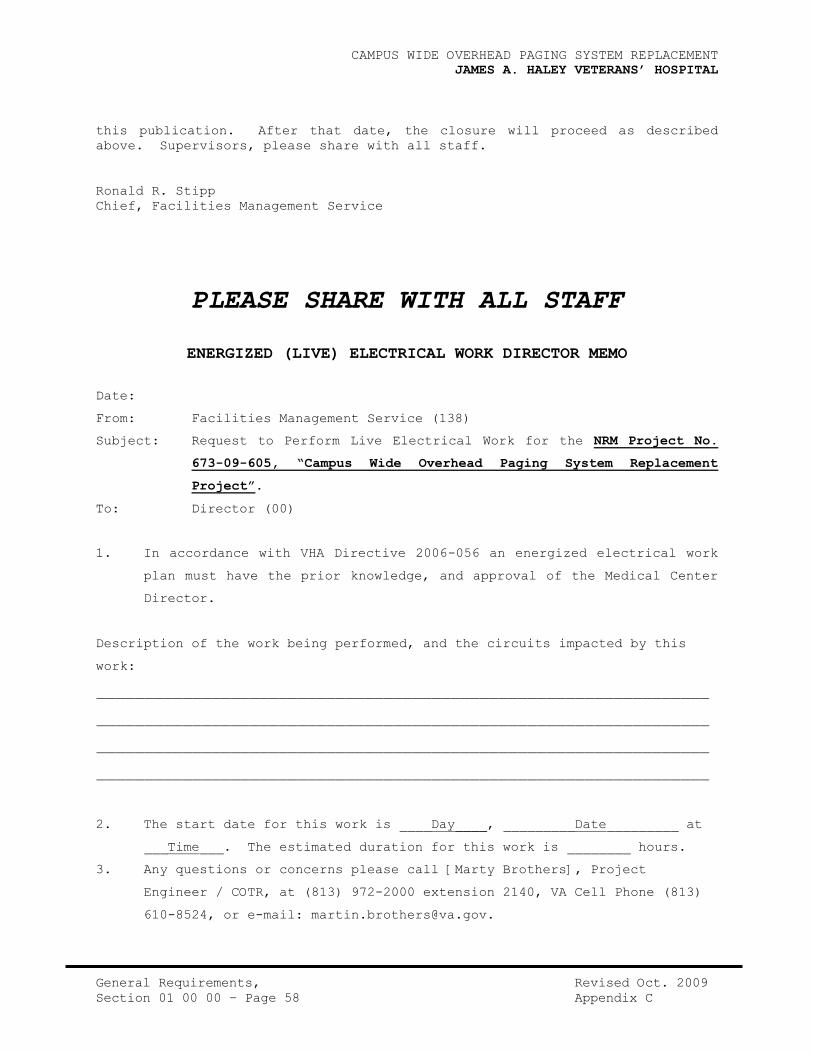
CAMPUS WIDE OVERHEAD PAGING SYSTEM REPLACEMENT
JAMES A. HALEY VETERANS’ HOSPITAL
General Requirements, Revised Oct. 2009
Section 01 00 00 – Page 58 Appendix C
this publication. After that date, the closure will proceed as described
above. Supervisors, please share with all staff.
Ronald R. Stipp
Chief, Facilities Management Service
PLEASE SHARE WITH ALL STAFF
ENERGIZED (LIVE) ELECTRICAL WORK DIRECTOR MEMO
Date:
From: Facilities Management Service (138)
Subject: Request to Perform Live Electrical Work for the NRM Project No.
673-09-605, “Campus Wide Overhead Paging System Replacement
Project”.
To: Director (00)
1. In accordance with VHA Directive 2006-056 an energized electrical work
plan must have the prior knowledge, and approval of the Medical Center
Director.
Description of the work being performed, and the circuits impacted by this
work:
________________________________________________________________
________________________________________________________________
________________________________________________________________
________________________________________________________________
2. The start date for this work is ____Day____, _________Date_________ at
___Time___. The estimated duration for this work is ________ hours.
3. Any questions or concerns please call [Marty Brothers], Project
Engineer / COTR, at (813) 972-2000 extension 2140, VA Cell Phone (813)
610-8524, or e-mail: [email protected].

CAMPUS WIDE OVERHEAD PAGING SYSTEM REPLACEMENT
JAMES A. HALEY VETERANS’ HOSPITAL
General Requirements, Revised Oct. 2009
Section 01 00 00 – Page 59 Appendix C
Ronald R. Stipp
Chief, Facilities Management Service
Approve / Disapprove
______________________________________________________
Stephen M. Lucas, Director (00) Date
Enclosure: (#)

CAMPUS WIDE OVERHEAD PAGING SYSTEM REPLACEMENT
JAMES A. HALEY VETERANS’ HOSPITAL
General Requirements, Revised Oct. 2009
Section 01 00 00 – Page 60 Attachment #1 - A
ATTACHMENT #1 - A
NOTIFICATION OF IMPAIRED FIRE PROTECTION BY CONTRACTOR PERSONNEL
PROJECT No. & TITLE: NRM Project No. 673-09-605, “Campus Wide Overhead Paging
System Replacement Project”
NAME OF FACILITY
_____________________________________________________________
NOTIFIED BY
_______________________________
TITLE __________________________
__________________________
COMPANY
______________________________________________________________________
NATURE OF IMPAIRMENT
____________________________________________________________________________
____________________________________________________________________________
PRECAUTIONS TO BE TAKEN
____________________________________________________________________________
____________________________________________________________________________
____________________________________________________________________________
CLOSED VALVE NO. ___ IN BLDG. NO. ________ LOCATED IN ROOM ________
CONTROLLING _______________________________________________________
ON DATE: Sn,M,T,W,Th,F,St _____ @ TIME ______________ AM/PM
BECAUSE:
____________________________________________________________________________
____________________________________________________________________________
ON DATE: Sn,M,T,W,Th,F,St _____ @ TIME ______________ AM/PM
COTR ________________________________________ WAS CONTACTED AT (813) 972-2000
ext. or (813) _______________________
DATE/TIME SAFETY OFFICER WAS CONTACTED AT EXT. 7598
__________________________
DATE/TIME EGCC OPERATOR/CEP WAS CONTACTED AT EXT. 7080
_______________________
DATE/TIME FIRE DEPARTMENT WAS CONTACTED AT (813) 971-3636
_______________________

CAMPUS WIDE OVERHEAD PAGING SYSTEM REPLACEMENT
JAMES A. HALEY VETERANS’ HOSPITAL
General Requirements, Revised Oct. 2009
Section 01 00 00 – Page 61 Attachment #1 - A
DATE/TIME RSFPE WAS CONTACTED AT ( __)______________

CAMPUS WIDE OVERHEAD PAGING SYSTEM REPLACEMENT
JAMES A. HALEY VETERANS’ HOSPITAL
General Requirements, Revised Oct. 2009
Section 01 00 00 – Page 62 Attachment #1 - B
ATTACHMENT #1 - B
NOTIFICATION OF RESTORED FIRE PROTECTION BY CONTRACTOR PERSONNEL
PROJECT No. & TITLE: NRM Project No. 673-09-605, “Campus Wide Overhead Paging
System Replacement Project”
NAME OF FACILITY
_____________________________________________________________
NOTIFIED BY
_______________________________
TITLE __________________________
__________________________
COMPANY
______________________________________________________________________
NATURE OF IMPAIRMENT
____________________________________________________________________________
____________________________________________________________________________
AND FULL PROTECTION RESTORED, EXCEPT
____________________________________________________________________________
____________________________________________________________________________
____________________________________________________________________________
OPENED VALVE NO. ___ IN BLDG. NO. ________ LOCATED IN ROOM ________
CONTROLLING _______________________________________________________
ON DATE: Sn,M,T,W,Th,F,St _____ @ TIME ______________ AM/PM
BECAUSE:
____________________________________________________________________________
____________________________________________________________________________
ON DATE: Sn,M,T,W,Th,F,St _____ @ TIME ______________ AM/PM
COTR ________________________________________ WAS CONTACTED AT (813) 972-2000
ext. or (813) _______________________
DATE/TIME SAFETY OFFICER WAS CONTACTED AT EXT. 7598
__________________________
DATE/TIME EGCC OPERATOR/CEP WAS CONTACTED AT EXT. 7080
_______________________
DATE/TIME FIRE DEPARTMENT WAS CONTACTED AT (813) 971-3636
_______________________

CAMPUS WIDE OVERHEAD PAGING SYSTEM REPLACEMENT
JAMES A. HALEY VETERANS’ HOSPITAL
General Requirements, Revised Oct. 2009
Section 01 00 00 – Page 63 Attachment #1 - B
DATE/TIME RSFPE WAS CONTACTED AT ( __)______________

CAMPUS WIDE OVERHEAD PAGING SYSTEM REPLACEMENT
JAMES A. HALEY VETERANS’ HOSPITAL
General Requirements, Revised Oct. 2009
Section 01 00 00 – Page 64 Attachment #2
ATTACHMENT #2
NOTIFICATION OF HOT WORK OPERATIONS BY CONTRACTOR PERSONNEL (BURN PERMIT)
FOR PROJECT No. & TITLE: NRM Project No. 673-09-605, “Campus Wide Overhead
Paging System Replacement Project”
NAME OF FACILITY ____________________________________________________________
BUILDING No. & NAME: __________________________________________________
ON FLOORS: __________________________________________________________________
ON DATE: Sn,M,T,W,Th,F,St _____ @ TIME _______________ _AM/PM
WORK TO BE DONE:
_____________________________________________________________________________
_____________________________________________________________________________
_____________________________________________________________________________
SPECIAL PRECAUTIONS:
_____________________________________________________________________________
_____________________________________________________________________________
_____________________________________________________________________________
NAME OF FIRE WATCH PERSON IF APPLICABLE:
_____________________________________
COMMENTS:
_____________________________________________________________________________
_____________________________________________________________________________
_____________________________________________________________________________
_____________________________________________________________________________
NOTIFIED BY _________________________________________________________________
NOTIFIERS SIGNATURE & DATE __________________________________________________
TITLE & PHONE No. ___________________________________________________________
CONTRACTOR __________________________________________________________________
COTR ____________________________________________
APPROVAL ____________________
COTR SIGNATURE & DATE _______________________________________________________
SAFETY STAFF MEMBER _________________________________________________________
SAFETY SIGNATURE & DATE _____________________________________________________

CAMPUS WIDE OVERHEAD PAGING SYSTEM REPLACEMENT
JAMES A. HALEY VETERANS’ HOSPITAL
General Requirements, Revised Oct. 2009
Section 01 00 00 – Page 65 Attachment #3
ATTACHMENT #3
HOT WORK FIRE SAFETY CHECK LIST FOR OPERATIONS AREA INSPECTION
PROJECT NO. & TITLE: NRM Project No. 673-09-605, “Campus Wide Overhead Paging
System Replacement Project”
DATE:______________
Floor swept clean of combustibles.
Floors wet down, covered with damp sand, metal or other shields.
Combustibles material or flammable liquids removed from area,
whenever possible.
Combustibles and flammable liquids protected with covers, guards,
or metal shields.
All wall and floor openings covered.
Covers suspended beneath work to collect sparks.
WORK BEING DONE ON WALLS OR CEILINGS
Ensure wall construction is noncombustible and is without
combustible covering.
Move combustibles away from opposite side of wall.
WORK BEING DONE ON ENCLOSED EQUIPMENT-(TANKS, DUCTS, ETC.)
Remove all combustibles from enclosures.
Purge containers of flammable vapors. Ensure continuous purge so
no vapors accumulate during work.
FIRE WATCH
To be provided during and until 30 minutes after operation.
Provided with a 10-pound dry chemical or halon extinguisher and
small hose.
Trained in use of equipment and in sounding fire alarm.
FINAL CHECK-UP
To be made 30 minutes after completion of any operation unless
fire watch is provided.
Notify Safety Office (extension 7292) when work is complete.
(Contractors - notify COTR)
Notify Graphic Control Center (extension 7080), if any fire zones
were by-passed
HOT WORK LOCATION ___________________________________________________________
NOTIFIERS SIGNATURE & DATE __________________________________________________
NAME & PHONE No. ____________________________________________________________
CONTRACTOR
___________________________________________________________________

CAMPUS WIDE OVERHEAD PAGING SYSTEM REPLACEMENT
JAMES A. HALEY VETERANS’ HOSPITAL
General Requirements, Revised Oct. 2009
Section 01 00 00 – Page 66 Attachment #3
COTR SIGNATURE & DATE
________________________________________________________

CAMPUS WIDE OVERHEAD PAGING SYSTEM REPLACEMENT
JAMES A. HALEY VETERANS’ HOSPITAL
General Requirements, Revised Oct. 2009
Section 01 00 00 – Page 67 Attachment #4
ATTACHMENT #4
CONSTRUCTION FIRE SAFETY CHECK LIST
(For protection of VA property, patients, visitors and personnel)
PROJECT # & Title: NRM Project No. 673-09-605, “Campus Wide Overhead Paging
System Replacement Project”
DATE:______________
A. FIRE EXTINGUISHERS (OSHA 1926.150[c])
___________ (1) Extinguisher available within 100 feet. Extinguisher rated
not less than 2A.
___________ (2) If flammable liquids or gases present, a fire extinguisher
rated not less than 10B within 50 feet.
B. IGNITION HAZARDS (OSHA 1926.1511[a])
___________ (1) Internal combustion engines located away from combustibles.
___________ (2) Smoking is prohibited in fire hazard areas (flammables,
combustibles).
C. INDOOR STORAGE (OSHA 1926.151[d])
___________ (1) Site kept free from accumulation of unnecessary
combustibles.
___________ (2) Storage shall not obstruct means of exits.
___________ (3) Clearance maintained around lights and heating units.
D. FLAMMABLE AND COMBUSTIBLE LIQUIDS (OSHA 1926.152)
___________ (1) Approved containers.
___________ (2) No storage in areas of exits, stairways or people traffic
areas.
___________ (3) Max. 25 gal. In room – otherwise approved storage cabinet.
E. TEMPORARY HEATING DEVICES (OSHA 1926.154)
___________ (1) Adequate ventilation for workmen and heater combustion.
___________ (2) Clearance of combustibles from heaters at least 3 feet.
___________ (3) Stability of heater.
F. SIGNS AND BARRICADES (OSHA 1926.200)
___________ (1) Danger signs where immediate hazards exist.
___________ (2) Caution signs where potential hazards exist.
___________ (3) Safety instruction signs where necessary.
___________ (4) Barricades where necessary to protect persons from hazards.
G. WELDING AND CUTTING – HOT WORK PERMIT REQUIRED (NFPA-51B & OSHA 1910.252)
___________ (1) Inspection of area before permit given.

CAMPUS WIDE OVERHEAD PAGING SYSTEM REPLACEMENT
JAMES A. HALEY VETERANS’ HOSPITAL
General Requirements, Revised Oct. 2009
Section 01 00 00 – Page 68 Attachment #4
___________ (2) Distance from combustibles 35 feet.
___________ (3) Fire extinguisher in immediate area.
___________ (4) Wall and floor openings covered.
___________ (5) No flammable liquids present.
___________ (6) Inspection after work.
H. ELECTRICAL (OSHA 1924.400-2, 1926.302, & NFPA 241-4)
___________ (1) All temporary wiring grounded and in accordance with
National Electric Code (NEC).
___________ (2) Precautions taken to make any open wiring inaccessible to
other than authorized personnel.
___________ (3) Temporary light bulb equipped with guards, use heavy duty
cords, and not suspended by their cords unless specifically
designed for that use.
___________ (4) Runs of open conductors located away from possible damage
and fastened at intervals of no greater than 10 feet.
___________ (5) Outlets in construction sites have GFCI or assured
equipment grounding.
___________ (6) Extension cords protected from damage. No worn or frayed
cables. Not hung from nails or suspended by wire.
___________ (7) Fuses or circuit breaker provided for each feeder or branch
circuit.
___________ (8) Electrical powered operated hand tools shall either be of
the approved double insulated type or properly grounded.
I. DEMOLITION (OSHA 1926.850-858 and NFPA 241 – Ch.7)
___________ (1) Electric, gas water, steam, etc. shut off prior to work.
___________ (2) Any utilities that are necessary to be maintained need
protection.
___________ (3) Masonry walls shall not be permitted to fall on floors such
that it would exceed the safe carrying capacity of the
floor.
___________ (4) Floor openings within 10 feet of any wall being demolished
shall be planked solid except when no one below.
___________ (5) The storage of waste material and debris shall not exceed
the floor loading limit.
___________ (6) Construction of dust barriers as needed (not OSHA).
___________ (7) Notification of shut off and protect smoke detectors, etc.
during day time only (not OSHA). Coordinated with COTR.
___________ (8) Precautions if floors are soaked with oil or flammable
liquids, if dust accumulation is present or other
combustibles a present and hot work is being performed.
___________ (9) Smoking is prohibited throughout demolition (NFPA 241, 7-4,
2).
___________ (10) Flammable and combustible liquids removed from area.
___________ (11) Water supplies must still be available from fire hydrants
in the vicinity of the structure or area.
___________ (12) Asbestos abatement, breakables (i.e., glass) shall be
removed prior to demolition.
J. TEMPORARY BUILDINGS, TRAILERS (NFPA 241, Ch.2)

CAMPUS WIDE OVERHEAD PAGING SYSTEM REPLACEMENT
JAMES A. HALEY VETERANS’ HOSPITAL
General Requirements, Revised Oct. 2009
Section 01 00 00 – Page 69 Attachment #4
___________ (1) Temporary offices, trailers, sheds, etc. of combustible
construction at least 30 feet from permanent buildings.
___________ (2) Only safety installed approved heating devices used. Ample
clearance around stoves, heaters and chimneys per NFPA 211.
K. ROOFING OPERATIONS (NFPA 241, Ch.6)
___________ (1) Asphalt and tar kettles located outside the building or on
a noncombustible roof away from combustibles. Kettles must
have gravity lids, tight fitting.
___________ (2) Torch applied roofing systems shall be installed using
extreme caution. Follow manufacturer’s instructions.
Caution around roof openings, penetrations or flashings.
___________ (3) Fire extinguisher, 20-B minimum, within 30 feet of roof
kettle. At least one extinguisher 2A:20-B:C on the roof
being repaired; also one within 30 feet of torch applied
roofing equipment.
___________ (4) Fuel containers at least 10 feet away from burner flame.
___________ (5) Notify building occupants who might be affected.
Coordinate with C.O.T.R.
___________ (6) Investigate location of supply air intakes. Coordinate
shutdowns as necessary with COTR.
___________ (7) Roof edges will be guarded by means of typical roof
protection or a safety monitoring system.
L. EXIT PATHWAYS (NFPA 241, Ch.5; also reference NFPA 101)
___________ (1) Every building and area will remain accessible to fire
department apparatus and personnel. Roadways will be
maintained with 20 feet of all buildings.
___________ (2) Adequate egress paths, including stairs and corridors, will
be maintained at all times. Exits may only be blocked
temporarily if unavoidable and when adequate alternate
measures are provided(signage, temporary fire detection,
training, etc.) to warn personnel. Coordinate with COTR.
WORK LOCATION _______________________________________________________________
NOTIFIERS SIGNATURE & DATE __________________________________________________
NAME & PHONE No. ____________________________________________________________
CONTRACTOR
___________________________________________________________________
COTR SIGNATURE & DATE
________________________________________________________

CAMPUS WIDE OVERHEAD PAGING SYSTEM REPLACEMENT
JAMES A. HALEY VETERANS’ HOSPITAL
General Requirements, July 2007
Section 01 00 00 – Page 70 HPM No. 138-03
JAMES A. HALEY VETERANS HOSPITAL HOSPITAL POLICY MEMORANDUM
TAMPA, FLORIDA 33612 NO. 138-03
JULY 2007
SAFETY & HEALTH DURING CONSTRUCTION ACTIVITIES
1. PURPOSE: To establish policy and procedures to ensure that
construction projects will be planned, coordinated and regularly inspected to
ensure compliance with applicable fire, infection control, environmental,
security, safety and occupational health regulations and policies.
2. SCOPE: The policies hereby established apply to the James A. Haley
Veterans’ Hospital, Outpatient Clinics, the Community-Based Outpatient
Clinics (CBOC’s), and all other facilities owned or leased by the Hospital.
3. POLICY:
A. In order to protect patients, staff, visitors and contractors from
safety and health hazards associated with construction activities, this
policy requires that strategies be established to control the hazards
inherent in conducting construction or maintenance operations in areas that
are occupied by all customers. These strategies include the assignment of
appropriate responsibility at all levels of the organization, establishing
and maintaining the necessary expertise to manage an effective construction
health and safety program, applying technical guidance and best practices to
assist in managing the program and providing a construction safety multi-
disciplinary committee to oversee and enforce the application of this policy.
B. Construction activities shall be defined to include delegated minor or
non-recurring maintenance projects performed by contractors, as well as
station-level projects performed by contractors or Facilities Management
personnel. Construction shall also include non-delegated projects including
majors, and James A. Haley Veterans' Hospital shall coordinate those
construction impacts with the project’s Resident Engineer through the Project
Section Supervisor. This definition also applies to enhanced-use and lease
projects related to structures for which the James A. Haley Veterans'
Hospital maintains management responsibility or authority.
C. The intention of this construction safety program is to reduce
the potential for injury and illness to VA patients, employees, and visitors
that might result from unsafe construction activities; to increase the level
of construction safety expertise of VA employees; to decrease the potential
for serious Occupational Safety and Health Administration (OSHA) violations;
to provide guidelines for addressing safety-related construction issues; and
to reduce the potential for property and liability exposures due to
construction-related activities.
4. DELGATION OF AUTHORITY AND RESPONSIBILITY: The Construction Safety
Committee is composed of a multi-disciplinary team consisting of Facilities
Management Service, Contracting, Safety, Infection Control, VA Police, and
Patient Safety as needed. All construction projects shall be assessed by the
committee and its peers according to OSHA Construction Safety Guidelines and
this policy.

CAMPUS WIDE OVERHEAD PAGING SYSTEM REPLACEMENT
JAMES A. HALEY VETERANS’ HOSPITAL
General Requirements, July 2007
Section 01 00 00 – Page 71 HPM No. 138-03
A. Chief, Facilities Management Service:
1) Ensures that construction activities performed by contractors and
Facilities Management employees comply with this policy.
2) Reviews and approves minutes of the Construction Safety
Committee. A copy of minutes is sent to the Chairperson, Occupational
Safety & Health Committee.
B. Projects Section Supervisor:
1) Chairs the Construction Safety Committee.
2) Ensures designated Competent Persons (CPs) have the
necessary training, experience and authority to carry out their
responsibilities with respect to safety and health during construction
activities.
Note: The designated competent person shall be defined by OSHA
Title 29 Code of Federal regulations.
3) Works through safety staff, COTRs, maintenance staff,
contractors and the Construction Safety Committee to plan, coordinate and
monitor the construction safety program for all projects at the facility.
4) Participates in periodic inspections of construction sites to
ensure compliance with safety elements of the construction contract and
performance of the program.
5) Supports the CPs, Safety Officer, Infection Control
Practitioner, Contracting Officer and Facilities Management staff in
implementation of the construction safety program.
6) Works with contracting staff to insure competent staff are
assigned as COTRs to oversee work.
C. Operations and Maintenance Section Supervisor:
1) Participates in OSHA’s 30-hour construction safety training
and refresher courses and serves as the competent person for all related in-
house construction activities.
2) Participates in periodic inspections of in-house construction
sites to ensure compliance with safety elements of the construction contract
and performance of the program.
3) Ensures in-house work forces have necessary training and
competency for tasks being performed.
D. Biomedical Engineering Section Supervisor:
1) Ensures all construction accomplished in support of major equipment
installations (as a part of the equipment purchase) are in compliance with
this policy and these procedures.
E. Contracting Officer (CO):

CAMPUS WIDE OVERHEAD PAGING SYSTEM REPLACEMENT
JAMES A. HALEY VETERANS’ HOSPITAL
General Requirements, July 2007
Section 01 00 00 – Page 72 HPM No. 138-03
1) Ensures safety elements of this policy are included in each
construction contract.
2) Requests past safety records of prospective contractors for
evaluation by Safety Office.
3) Supports the CP, Safety Officer, Resident Engineer, and
appropriate staff in implementing the construction safety program.
F. Contracting Officer’s Technical Representative (COTR):
1) Participates in OSHA’s 30-hour construction safety training
program and refresher courses.
2) Is trained and designated as a CP for the purposes of this
policy.
3) As the team member most familiar with the technical aspects of
his/her designated project, inspects his/her projects on a daily basis to
identify and document deficiencies in the work including safety and
infection control. Acts to correct deficiencies whenever possible and
coordinate with CO when contractual concerns are involved.
4) Reports all deficiencies to the Construction Safety Committee
whether corrected or not.
5) Consults with other members of the committee, as
appropriate, to assure that all deficiencies are handled properly.
6) Consults with members of the team, during design or planning,
to establish the risks to be addressed and the degree of protection
appropriate to the situation.
7) Monitors compliance with relevant safety and health
requirements by the contractor in the field.
G. VA Competent Person (CP):
1) Reviews project design submissions to assure project compliance
with these policies.
2) Monitors and inspects construction and renovation work sites
periodically to ensure compliance with polices and safety elements of the
construction contract using the attached Daily Construction Site Inspection
Sheet (Attachment "A").
3) Maintains competence in the general inspection of work sites
during construction, renovation and maintenance, which fall under the
purview of this policy.
4) Maintains a high level of competency when serving as a
Competent Person for VA staff performing any construction activities.
Note: The VA CP does not take the place of the contractor’s
competent person nor acts on their behalf. The VA CP
determines if the contractor is meeting VA standards and
contractual requirements for safety and OSHA compliance.
When these standards and contract requirements are not being
met, the VA Contracting Officer’s Technical Representative

CAMPUS WIDE OVERHEAD PAGING SYSTEM REPLACEMENT
JAMES A. HALEY VETERANS’ HOSPITAL
General Requirements, July 2007
Section 01 00 00 – Page 73 HPM No. 138-03
(COTR) and/or CP must take immediate action to prevent
injury, non-compliance, and/or property damage.
5) Participates in OSHA’s 30-hour construction safety training and
refresher courses.
6) Ensures that the specific safety requirements for construction
operations are implemented and continuously observed during the course of
all projects subject to this policy.
7) Approves corrective actions.
8) Stops unsafe work or activities non-compliant with the
contract or OSHA and notifies the Contracting Officer immediately.
9) Communicates mainly with the contractor CP on questions of safety.
H. Safety Office Staff:
1) Participates in OSHA’s 30-hour construction safety training and
refresher courses.
2) Ensures necessary and relevant ILSMs (Interim Life Safety
Measures) are established and implemented in accordance with HPM 138-15.
Conducts required additional training for compliance with identified ILSMs.
3) Renders technical advice and assistance as required in
connection with life safety and fire protection issues during construction
and project design and development.
4) Oversees compliance with OSHA and other relevant construction
safety regulations.
5) Conducts periodic construction site hazard surveillance
inspections.
6) Provides guidance on environmental issues during design
stage.
7) Monitors contractor conformance to contract specifications,
including environmental compliance and pollution prevention.
8) Evaluates past safety records of prospective contractors and
shares this information with Contracting Officers.
I. Infection Control:
1) Advises and/or provides recommendations on exposure mitigation
and the prevention of facility associated infections in patients, staff, and
visitors.
2) Coordinates with the COTR of each construction project (in-
house and contract) to conduct an Infection Control Risk Assessment (ICRA)
during the planning and/or design stage of the work in accordance with HPM
138-24. ICRAs must be documented in writing and focus on eliminating, or
minimizing, the risk of infection during construction and renovation
activities. COTR will relay details of ICRAs to the Contracting Officer
(CO) during the project planning stage.

CAMPUS WIDE OVERHEAD PAGING SYSTEM REPLACEMENT
JAMES A. HALEY VETERANS’ HOSPITAL
General Requirements, July 2007
Section 01 00 00 – Page 74 HPM No. 138-03
3) Monitors infection control during construction activities as
indicated in ICRA for that project.
J. The Construction Safety Committee:
1) Oversees and enforces the application of this policy.
2) Determines the scope and depth of safety, infection control,
environmental and security procedures appropriate for all construction
work.
3) Evaluates the effectiveness of the construction safety program
in an annual report to the Hospital’s Occupational Safety and Health
Committee.
K. Police Service:
1) Addresses security issues and develops control strategies
related to construction activities.
2) Conducts periodic surveillance of site security and the
integrity of barriers for trenches and other hazards.
5. PROCEDURES:
A. The Construction Safety Committee:
1) Meets monthly to review and documents safety issues with
construction activities.
2) Develops threshold criteria for each level of intervention.
For example, after review, some projects may require only VA CP surveillance
to ensure employee safety and OSHA compliance, while other projects will
require all disciplines to be involved.
3) Ensures submittals for contract construction or renovation work
include the names, qualifications, and training dates for the contractors’
CPs designated to administer the site-specific safety program, as well as
the CPs for other activities as required by OSHA regulation (such as
scaffolds, cranes, excavations, etc).
4) Participates, when necessary, in construction and safety
planning. The Construction Safety Committee must become involved early in
the process and can offer comments and suggestions to the CO and COTR on
items related to safety and construction safety issues.
5) Ensures the construction safety program includes periodic
construction site hazard surveillance activities with appropriate
membership, scope, and frequency for each project as determined by the CP,
the ILSMs and ICRA reports. Hazard surveillance activities must be
documented with date, time, members of the inspection team, deficiencies,
type of corrective action, and time and date of correction. Ensures
corrective actions are tracked to completion.
6) Implements procedures to ensure general contractors exercise
their responsibility for ensuring subcontractors comply with this safety and
health policy and all other related contract requirements.

CAMPUS WIDE OVERHEAD PAGING SYSTEM REPLACEMENT
JAMES A. HALEY VETERANS’ HOSPITAL
General Requirements, July 2007
Section 01 00 00 – Page 75 HPM No. 138-03
7) Ensures all contractors entering VA property comply with the
Hospital’s Security Management Program. As a minimum, contractors must
notify and obtain permission from VA Police, be identified by project and
employer, and be restricted from unauthorized access.
8) Requires the contractors’ CPs to implement and maintain effective
safety programs that identify and control hazards that may cause injury or
illness to VA patients, staff, visitors, and contractor employees.
9) Ensures that VA staff receives training as follows:
a) Project Section Supervisor, Appointed CPs,
Contracting Officer’s Technical Representatives (COTRs) and facility Safety
Office Staff must complete OSHA’s 30-hour construction safety course before
independently managing construction activities.
b) Facilities Management Supervisors and Construction Staff
must complete OSHA’s10-hour Construction Safety course before independently
managing construction activities.
10) Ensures that construction contracts awarded after July 31,
2005 specify that on-site general and sub-contractor’s construction workers
have completed the OSHA 10-hour construction worker course, the 30-hour
construction course, or other relevant competency training, as determined by
the VA CP with input from the Construction Safety Committee. The
determination for training is based on the project hazards and complexity,
State and Federal regulations and VA requirements.
6. REFERENCES:
A. VHA Construction Safety Guidebook, 2005, Center for
Engineering and Occupational Safety and Health available electronically at:
Http://vaww.ceosh.med.va.gov.
B. National Fire Protection Association (NFPA) Standards.
Note: Current NFPA Standards are available in Safety and
Project Section Offices.
C. OSHA Regulations for Construction Safety, 29 CFR
1926, available at:
http://www.osha.gov
D. Current JCAHO Standards from the Joint Commission on the
Accreditation of Healthcare Organizations.
E. VHA Directive 7701, Occupational Safety and Health.
F. VHA Handbook 7701.1, Occupational Safety and Health Program
Procedures.
G. VA Directive 7700, Occupational Safety and Health.
H. VHA Directive 2004-012, Safety and Health During Construction
Activities.
I. Hospital Policy Memorandum 132-04, “Security Management Program”.

CAMPUS WIDE OVERHEAD PAGING SYSTEM REPLACEMENT
JAMES A. HALEY VETERANS’ HOSPITAL
General Requirements, July 2007
Section 01 00 00 – Page 76 HPM No. 138-03
J. Hospital Policy Memorandum 138-15, “Interim Life Safety Measures”.
K. Hospital Policy Memorandum 138-24, “Infection Control During
Construction and Renovation”.
7. RECISSION: None.
8. FOLLOW-UP RESPONSIBILITY: Project Section Supervisor, 138P,
Facilities Management Service.
Stephen M. Lucas
Director
Attachment:
A. Daily Construction Site Inspection Sheet
Distribution: Electronic Distribution to All Employees
HOSPITAL POLICY MEMORANDUM
NO. 138-03
ATTACHMENT "A"
DAILY CONSTRUCTION SITE INSPECTION
Date: _________________ Inspector: ______________________ Project No.:
_________________
Description Yes No Comments
Contractor acknowledge asbestos in writing
Adequate barriers in place

CAMPUS WIDE OVERHEAD PAGING SYSTEM REPLACEMENT
JAMES A. HALEY VETERANS’ HOSPITAL
General Requirements, July 2007
Section 01 00 00 – Page 77 HPM No. 138-03
Smoke proof
Dust proof
Signage in place
Applicable codes complied with
Occupational Safety & Health Admin. (OSHA)
compliance
Interim Life Safety in place
Staff trained regarding Interim Life
Safety
Temporary fire protection in
place/fire watch
Contractors aware of egress routes
*Increase in fire drills, other training
All exits clear
Free access to Emergency Services
Alternate access for public and emergency
use
Additional fire fighting staff & equipment
available
Smoking is strictly prohibited
Construction site clean and orderly
Hazard surveillance occurring? How often?
Staff informed if adjacent areas affected
Construction site restricted
Local authorities aware of Interim Life
Safety
Effective site storage of materials, other
Fire zones maintained, staff aware of
changes
Contractor confirms egress routes for
staff clear
Hot work permits are being issued.
Penetrations through firewalls are
properly sealed
COTR/Contractor: Complete applicable items as required and in accordance with
those items checked on checklist.

CAMPUS WIDE OVERHEAD PAGING SYSTEM REPLACEMENT
JAMES A. HALEY VETERANS’ HOSPITAL
General Requirements, July 2007
Section 01 00 00 – Page 78 HPM No. 138-14
JAMES A. HALEY VETERANS’ HOSPITAL HOSPITAL POLICY MEMORANDUM TAMPA,
FLORIDA 33612 NO. 138-14
JULY 2007
ASBESTOS OPERATIONS AND MAINTENANCE PROGRAM
1. PURPOSE: To establish policy governing identification, control,
maintenance, removal, and disposal of all Asbestos Containing Material (ACM),
located throughout the Hospital, and its Outpatient locations.
2. POLICY: It is the policy of the James A. Haley Veterans’ Hospital to
establish an effective Asbestos Operations and Maintenance Program (O&M) to
minimize exposure to building occupants by controlling activities that affect
all known ACM. This is accomplished by informing employees and contractors
where ACM is located, designating controlled areas and materials,
implementing safe work practices and procedures, providing staff with
appropriate training and equipment, and conducting periodic and systematic
surveillance of the ACM.
3. DELEGATION OF RESPONSIBILITY:
A. The Chief, Facilities Management Service is responsible for:
(1) Implementing and monitoring the Asbestos O&M Program to
ensure all phases of asbestos control and management are accomplished in
accordance with OSHA, EPA, VA, State and Local rules and regulations.
(2) Taking prompt and appropriate action to alleviate any
identifiable exposure hazards at the facility.
(3) Developing specifications and monitoring all outside
contractors performing services at the hospital to assure compliance with the
requirements of OSHA, EPA, VA, State and Local Municipality, as they pertain
to the safety of the patients, employees, and volunteers.
(4) Notifying, in writing, the Union Representative prior to
the start of any asbestos removal operation.
(5) Ensuring that Facilities Management Service maintains the
facility master file for all asbestos-related records and documentation,
except employee health records, which shall be filed in Occupational Health.
B. The Safety Office is responsible for:
(1) Providing overall direction and review of all asbestos-
related activities such as identification, control, maintenance, and
disposal.
(2) Coordinating annual training for Hospital personnel as

CAMPUS WIDE OVERHEAD PAGING SYSTEM REPLACEMENT
JAMES A. HALEY VETERANS’ HOSPITAL
General Requirements, July 2007
Section 01 00 00 – Page 79 HPM No. 138-14
delineated in the policy.
(3) Conducting and/or coordinating personal and area monitoring
in accordance with VA Directive 7700 and OSHA requirements (29 CFR 1910 and
1926).
(4) Identifying those employees who are required under the OSHA
regulations to participate in the Asbestos Medical Surveillance Program.
C. The Chief, Acquisition and Materiel Management Service (A&MMS) is
responsible for:
(1) Ensuring that this hospital does not procure materials
containing asbestos in excess of one percent (1%). Any exceptions to this
policy shall be approved on a case-by-case basis by the Designated Agency
Safety and Health Official (DASHO) in accordance with VA Directive 7700.
(2) Ensuring that affected contractors notify, in writing,
the local EPC Air Management Division at least 10 days prior to the start of
any demolition and/or asbestos removal operation in excess of 160 SF or 260
LF at this hospital or its affiliated facilities.
(3) Assuring that, for all spaces leased by the hospital, the
lessor provide a current (within the past 12 months) NESHAP (National
Emissions Standards for Hazardous Air Pollutants) asbestos survey performed
in order to determine the presence and condition of the ACM.
D. The Occupational Health Physician is responsible for:
(1) Scheduling and providing physical examinations for
personnel as established in HPM 11-84, Medical Surveillance Program.
(2) Providing clinical opinions to the Safety Office on the
advisability/ability of personnel to wear respiratory protection equipment in
accordance with HPM 138-12, Respiratory Protection Program.
E. Facilities Management Service Supervisors are responsible for:
(1) Implementing applicable asbestos control procedures as
outlined in this policy.
(2) Ensuring that employees covered under the Medical
Surveillance Program are entered into the program before performing asbestos-
related activities.
(3) Ensuring that protective equipment and
supplies are available, in proper
operating condition, and are properly utilized.
(4) Ensuring that affected employees attend the appropriate
asbestos training initially and annually thereafter.

CAMPUS WIDE OVERHEAD PAGING SYSTEM REPLACEMENT
JAMES A. HALEY VETERANS’ HOSPITAL
General Requirements, July 2007
Section 01 00 00 – Page 80 HPM No. 138-14
(5) Ensuring that employees, patients, volunteers, and visitors
who will be affected during the period of time that the work will be in
progress have been notified.
(6) Reporting asbestos exposure hazards or asbestos
deterioration to the
Safety Office in a timely manner.
F. Facilities Management Service Employees are responsible for:
(1) Verification of asbestos containing work areas (using
available Asbestos Survey data in the Safety Office) prior to initiating work
and following all applicable asbestos control procedures as outlined in this
policy.
(2) Reporting any apparent asbestos exposure hazard. Employees should
note deterioration of any asbestos materials when working throughout the
hospital and should report deteriorated conditions immediately upon
discovery to their supervisors.
(3) Immediately reporting to their supervisor all incidents
involving a possible exposure to airborne asbestos fibers so immediate
corrective action can be taken.
(4) Properly utilizing all required protective equipment and
supplies.
4. PROCEDURES:
A. The Asbestos Containing Material (ACM) in this hospital is
generally in good condition and located in areas that are not readily
accessible to hospital staff.
B. All individuals who may come in contact with ACM shall be
informed of its location to prevent inadvertent disturbance and exposure.
These individuals include Maintenance personnel, Housekeeping, and
Maintenance/Construction Contractors.
C. When maintenance, renovation, or alteration activity will result
in intended or likely disturbance of ACM, the work practices indicated in
Attachment A will be followed.
D. Identification of ACM shall be accomplished through an Asbestos
Assessment, which is updated annually. Current “as built” drawings will
indicate areas containing ACM. Areas will be labeled as containing ACM in
accordance with current OSHA Regulations.
E. Air monitoring measurements shall be taken in all areas
containing asbestos materials in accordance with Attachment “A”. Employee
representatives will be given a reasonable opportunity to observe air

CAMPUS WIDE OVERHEAD PAGING SYSTEM REPLACEMENT
JAMES A. HALEY VETERANS’ HOSPITAL
General Requirements, July 2007
Section 01 00 00 – Page 81 HPM No. 138-14
monitoring required by OSHA, EPA, this policy memorandum, or any applicable
regulation. Copies of all industrial hygiene and environmental records
related to such monitoring will be made available to exposed employees within
15 calendar days of receipt of laboratory results.
F. Environmental air monitoring shall be conducted at least semi-
annually. Environmental sampling may be reduced to once annually in isolated
areas that normally have minimal personnel activity. Monitoring is also
conducted prior to, during and after removal of asbestos materials.
G. The Safety Office or designee will collect personal air samples
periodically to determine compliance with the applicable OSHA Standard
activities. Personal samples will be collected during all removals and as
specified in Attachment A. VA Form 10-0018, VA Air Sampling Data Sheets, will
be used to document air samples requiring laboratory analysis. All air
monitoring records will be retained by the Facilities Management Service. All
air samples must be analyzed by an American Industrial Hygiene Association
(AIHA) accredited laboratory or an individual accredited through the Asbestos
Analyst Registry (AAR) Program.
H. The Safety Office or designee will conduct bulk sampling of any
material suspected of containing asbestos. All bulk samples must be analyzed
by a Laboratory accredited by EPA’s National Voluntary Laboratory Analysis
Program (NVLAP).
.
I. All affected employees shall be placed under the Medical
Surveillance Program as established in HPM 11-84.
J. All employees required to wear respiratory protection as outlined
in Attachment “A” shall be enrolled in the Respiratory Protection Program as
referenced in Hospital Policy Memorandum 138-12.
K. All asbestos fiber releases will be investigated by the Safety
Office.
L. All asbestos training will be coordinated by the Safety Office in
accordance with Attachment “A”.
M. In those rare instances, where laundering of asbestos
contaminated clothing is necessary, this shall be done by a knowledgeable
contractor. Contaminated clothing shall be transported in sealed impermeable
bags, or other closed, impermeable containers, and be labeled in accordance
with labeling requirements indicated within this policy.
N. The two most likely fiber release episodes involving disturbance
of ACM include: A water leak in the roof or pipe above the suspended ceiling,
and the appearance of debris in an occupied space or common area due to
unauthorized entry therein. In the event of asbestos fiber release, the
Safety Office shall be notified immediately to isolate contaminated areas and
to minimize the spread of asbestos fibers. During non-administrative hours
the Central Energy Plant Operator shall be contacted at extension 7080. The

CAMPUS WIDE OVERHEAD PAGING SYSTEM REPLACEMENT
JAMES A. HALEY VETERANS’ HOSPITAL
General Requirements, July 2007
Section 01 00 00 – Page 82 HPM No. 138-14
Central Energy Plant Operator shall immediately notify Safety Office
personnel of the incident.
5. REFERENCES:
A. 29 CFR 1910.20, 1910.135, 1910.1001, and 1926.1101
B. ANSI Z88.2 and Z88.6.
C. EPA Publication 560/5-85-024 and 20T-2003.
D. VA Directive 7700.
E. 40 CFR 61 and 763.
F. HPM 138-12 (Respiratory Protection Program).
G. HPM 11-84 (Medical Surveillance Program)
6. FOLLOW-UP-RESPONSIBILITY: Supervisory Safety Engineer,
Facilities Management Service (138) is responsible for updating this hospital
policy memorandum.
7. RESCISSION: HPM 138-14, dated May 2004.
Stephen M. Lucas
Director
Attachments
A – “Work Practices for Maintenance, Removal, and Disposal of ACM”
B – “Notification of Asbestos O & M Work forms and Asbestos O & M Checklist”
C – “Fiber Release Episode Report”
DISTRIBUTION: Electronic Distribution to All Employees

CAMPUS WIDE OVERHEAD PAGING SYSTEM REPLACEMENT
JAMES A. HALEY VETERANS’ HOSPITAL
General Requirements, July 2007
Section 01 00 00 – Page 83 HPM No. 138-14
JAMES A. HALEY VETERANS’ HOSPITAL HOSPITAL POLICY MEMORANDUM
TAMPA, FLORIDA 33612 NO. 138-14
ATTACHMENT “A”
JULY 2007
WORK PRACTICES FOR MAINTENANCE, REMOVAL AND DISPOSAL OF ACM
1. INTRODUCTION
This attachment is a set of maintenance and operation procedures
designed to minimize asbestos exposure to patients, visitors, staff,
maintenance personnel and other workers at the James A. Haley Veterans’
Hospital. The work practices are divided into four classes: Class I, II, III,
and IV. All work assignments involving ACM will be reviewed by the Safety
Office prior to the commencement of work.
2. CLASSIFICATIONS
A. Class I Asbestos Work - Activities involving the removal of
Thermal System Insulation (TSI) and surfacing Asbestos Containing Material
(ACM) and Presumed Asbestos Containing Material (PACM).
B. Class II Asbestos Work - Activities involving the removal of ACM
which is not thermal system insulation or surfacing material. This includes,
but is not limited to, the removal of asbestos containing wallboard, floor
tile and sheeting, roofing and siding shingles, and construction mastics.
C. Class III Asbestos Work - Repair and maintenance operations,
where “ACM”, including thermal system insulation and surfacing material, is
likely to be disturbed.
D. Class IV Asbestos Work - Maintenance and custodial activities
during which employees contact ACM and PACM and activities to clean up waste
and debris containing ACM and PACM. This includes, but is not limited to
stripping and buffing of vinyl asbestos floor tiles.
3. DEFINITIONS
A. Access. Access to regulated areas shall be limited to authorized
persons.
B. AHERA. Asbestos Hazard Emergency Response Act.
C. Amended water. Water to which surfactant (wetting agent) has been
added to increase the ability of the liquid to penetrate ACM.

CAMPUS WIDE OVERHEAD PAGING SYSTEM REPLACEMENT
JAMES A. HALEY VETERANS’ HOSPITAL
General Requirements, July 2007
Section 01 00 00 – Page 84 HPM No. 138-14
D. Asbestos. Asbestos includes chrysotile, amosite, crocidolite,
tremolite asbestos, anthophyllite asbestos, actinolite asbestos, and any of
these minerals that has been chemically treated and/or altered. For purposes
of this policy, “asbestos” includes PACM, as defined below.
E. Asbestos Box. A prefabricated mobile enclosure system designed to
isolate work area for a single employee. Negative pressure is maintained in
the box with a HEPA vacuum.
F. Asbestos-containing material (ACM). Any material containing more
than one percent asbestos.
G. Competent Person. One who is capable of identifying existing
asbestos hazards in the workplace and selecting the appropriate control
strategy for asbestos exposure, who has the authority to take prompt
corrective measures to eliminate them. In addition, for Class I, II and III
work who is specially trained in a training course which meets the criteria
of EPA’s Model Accreditation Plan (40 CFR 763) for supervisor.
H. Demarcation. The regulated area shall be demarcated in any manner
that minimizes the number of persons within the area and protects persons
outside the area from exposure to airborne concentrations of asbestos. Where
critical barriers or negative pressure enclosures are used, they may
demarcate the regulated area. Signs shall be provided and displayed pursuant
to the requirements of this section.
I. Demolition. The wrecking or taking out of any load-supporting
structural member and any related razing, removing, or stripping of asbestos
products.
J. Disturbance. A disturbance is contact which releases fibers from
ACM or PACM or debris containing ACM or PACM. This term includes activities
that disrupt the matrix of ACM or PACM, render ACM or PACM friable, or
generate visible debris. Disturbance includes cutting away small amounts of
ACM and PACM, no greater than the amount which can be contained in one
standard sized glove bag or waste bag in order to access a building
component. In no event shall the amount of ACM or PACM so disturbed exceed
that which can be contained in one glove bag or waste bag which shall not
exceed 60 inches in length and width.
K. Employee exposure. Exposure to airborne asbestos that would occur
if the employee were not using respiratory protective equipment.
L. Equipment room (change room). A contaminated room located within
the decontamination area that is supplied with impermeable bags or containers
for the disposal of contaminated protective clothing and equipment.
M. Excursion limit. The employer shall ensure that no employee is
exposed to an airborne concentration of asbestos in excess of 1.0 fiber per
cubic centimeter of air (1 f/cc) as averaged over a sampling period of thirty
(30) minutes as determined by using recognized analytical techniques.

CAMPUS WIDE OVERHEAD PAGING SYSTEM REPLACEMENT
JAMES A. HALEY VETERANS’ HOSPITAL
General Requirements, July 2007
Section 01 00 00 – Page 85 HPM No. 138-14
N. Fiber. A particulate form of asbestos, 5 micrometers or longer,
with a length-to-diameter ratio of at least 3 to 1.
O. Glove bag. An impervious plastic bag-like enclosure affixed
around an asbestos-containing material, with glove-like appendages through
which material and tools may be handled.
P. High-efficiency particulate air (HEPA) filter. A filter capable
of trapping and retaining at least 99.97 percent of all mono-dispersed
particles of 0.3 micrometers in diameter.
Q. Intact. Intact ACM is material that has not crumbled, been
pulverized, or otherwise deteriorated so that it is no longer likely to be
bound with its matrix.
R. Mini Enclosure. One or more layers of plastic sealed over all
openings into a work area or any other similarly placed physical barrier
sufficient to prevent airborne asbestos in a work area from migrating to an
adjacent area. Negative pressure is maintained inside by a HEPA vacuum or
negative air machine.
S. Modification. A changed or altered procedure, material or
component of a control system, which replaces a procedure, material or
component of a required system. Omitting a procedure or component, or
reducing or diminishing the stringency or strength of a material or component
of the control system is not a “modification”.
T. Negative Initial Exposure Assessment. A demonstration by the
employer, which complies that employee exposure during an operation is
expected to be consistently below the PEL.
U. Permissible exposure limits (PELS) . The employer shall ensure
that no employees is exposed to an airborne concentration of asbestos in
excess of 0.1 fiber per cubic centimeter of air as an eight (8) hour time-
weighted average (TWA) as determined by using recognized analytical
techniques.
V. Presumed Asbestos Containing Material (PACM). Thermal system
insulation and surfacing material found in buildings constructed no later
than 1980.
W. Prohibited activities. The employer shall ensure that employees
do not eat, drink,
smoke, chew tobacco or gum, or apply cosmetics in the regulated area.
X. Regulated area. An area established by the employer to
demarcate areas where Class I, II, and III asbestos work is conducted, and
any adjoining area where debris and waste from such asbestos work accumulate;
and work area within which airborne concentrations of asbestos, exceed or
there is a reasonable possibility they may exceed the permissible exposure

CAMPUS WIDE OVERHEAD PAGING SYSTEM REPLACEMENT
JAMES A. HALEY VETERANS’ HOSPITAL
General Requirements, July 2007
Section 01 00 00 – Page 86 HPM No. 138-14
limit.
Y. Removal. All operations where ACM and/or PACM is taken out or
stripped from structures or substrates, and includes demolition operations.
Z. Renovation. A renovation is the modifying of any existing
structure, or portion thereof.
AA. Repair. A repair is overhauling, rebuilding, reconstructing, or
reconditioning of structures or substrates, including encapsulation or other
repair of ACM or PACM attached to structures or substrates.
BB. Surfacing ACM. Material that is sprayed, troweled-on or otherwise
applied to surfaces (such as acoustical plaster on ceilings and fireproofing
materials on structural members, or other materials on surfaces for
acoustical, fireproofing, and other purposes) which contains more than 1%
asbestos.
CC. Thermal system insulation (TSI). ACM applied to pipes, fittings,
boilers, breeching, tanks, ducts or other structural components to prevent
heat loss or gain.
4. GENERAL PROCEDURES FOR CLASSES I, II, and III
A. Air Monitoring.
(1) Daily Monitoring. Daily monitoring shall be conducted that
is representative of the exposure of each employee who is assigned to work
within a regulated area. Until exposure monitoring documents that employees
on that job will not be exposed in excess of the PELs, or otherwise a
negative exposure assessment is made, it shall be presumed that employees are
exposed in excess of the TWA and excursion limit.
(2) Negative Exposure Assessment.
A negative exposure assessment can be demonstrated for any
one specific asbestos job which will be performed by employees who have been
trained in compliance with this policy and by employee exposures below the
PELs indicated by data which conform to the following criteria:
1. Objective data demonstrating that the product
or material containing asbestos minerals or the activity involving such
product or material cannot release airborne fibers in concentrations
exceeding the TWA and excursion limit under those work conditions having the
greatest potential for releasing asbestos or
2. Where monitoring of prior asbestos jobs for the
PEL and the excursion limit within twelve (12) months of the current or
projected job the monitoring and analysis were performed in compliance with
the asbestos standard in effect; and the data were obtained during work
operations conducted under workplace conditions “closely resembling” the

CAMPUS WIDE OVERHEAD PAGING SYSTEM REPLACEMENT
JAMES A. HALEY VETERANS’ HOSPITAL
General Requirements, July 2007
Section 01 00 00 – Page 87 HPM No. 138-14
processes, type of material, control methods, work practices, and
environmental conditions used and prevailing in the Hospital’s current
operations, the operations were conducted by employees whose training and
experience are no more extensive than that of employees performing the
current job, and these data show that under the conditions prevailing and
which will prevail in the current workplace there is a high degree of
certainty that employee exposures will not exceed the TWA and excursion limit
or
3. The results of initial exposure monitoring of
the current job made from breathing zone air samples that are representative
of the 8-hour TWA and 30-minute short-term exposures of each employee
covering operations which are most likely during the performance of the
entire asbestos job to result in exposure over the PELs.
(3) Periodic Monitoring. When daily monitoring is not required
due to negative exposure data periodic monitoring will be conducted at the
discretion of the Safety Office. If the PEL is exceeded during periodic
monitoring, daily monitoring shall be reinitiated. Periodic monitoring of all
work shall be performed where exposures may exceed a PEL, at intervals
sufficient to document the validity of the exposure prediction.
B. Isolation Procedures.
(1) HVAC systems shall be isolated in the regulated area by
sealing with a double layer of 6 mil plastic or the equivalent.
(2) Impermeable drop cloths shall be placed on surfaces beneath
all removal activity.
(3) All objects within the regulated area shall be covered with
impermeable drop cloths or plastic sheeting which is secured by duct tape or
an equivalent.
C. Engineering Controls.
(1) Vacuum cleaners equipped with HEPA filters to collect all
debris and dust containing ACM and PACM.
(2) Wet methods, or wetting agents, to control employee
exposures during asbestos handling, mixing, removal, cutting, application,
and cleanup, except where it can be demonstrated that the use of wet methods
is infeasible due to for example, the creation of electrical hazards or
equipment malfunction, and, in roofing, slipping hazards.
(3) Prompt clean-up and disposal of wastes and debris
contaminated with asbestos in leak-tight containers.
CAMPUS WIDE OVERHEAD PAGING SYSTEM REPLACEMENT
JAMES A. HALEY VETERANS’ HOSPITAL
General Requirements, July 2007
Section 01 00 00 – Page 88 HPM No. 138-14
(4) Local exhaust ventilation equipped with HEPA filter dust
collection systems.
(5) Enclosure or isolation of processes producing asbestos
dust.
D. Prohibitions. The following work practices and engineering
controls shall not be used for asbestos related work which disturbs ACM or
PACM, regardless of measured levels of asbestos-exposure or the results of
initial exposure assessment.
(1) High-speed abrasive disc saws that are not equipped with
point of cut ventilator or enclosures with HEPA filtered exhaust air.
(2) Compressed air used to remove asbestos, or materials
containing asbestos, unless the compressed air is used in conjunction with an
enclosed ventilation system designed to capture the dust cloud created by the
compressed air.
(3) Dry sweeping, shoveling or other dry clean-up of dust and
debris containing ACM and PACM.
(4) Employee rotation as a means of reducing employee exposure
to asbestos.
E. Personal Protective Equipment.
(1) Protective Clothing. Employees shall be provided and
required to use protective clothing, such as coveralls or similar whole-body
clothing, head coverings, gloves, and foot coverings. Protective clothing
must be cleaned with a HEPA vacuum before it is removed and disposed of as
asbestos waste material.
(2) Respirator Selection. The Safety Office shall select and
provide, at no cost to the employee, the appropriate respirator, and the
Supervisor shall ensure that the employee uses the respirator provided.
(3) Inspection of protective clothing. The Supervisor shall
examine work suits worn by employees at least once per work shift for rips or
tears that may occur during performance of work. When rips or tears are
detected while an employee is working, rips and tears shall be immediately
mended, or the work suit shall be immediately replaced.
F. Labels.
(1) Labels shall be affixed to all products containing asbestos
and to all containers containing such products, including waste containers.
Where feasible, installed asbestos products shall contain a visible label.
(2) Labels shall be used in accordance with the requirements of
29 CFR 1910.1200(f) of OSHA’s Hazard Communication Standard, and shall

CAMPUS WIDE OVERHEAD PAGING SYSTEM REPLACEMENT
JAMES A. HALEY VETERANS’ HOSPITAL
General Requirements, July 2007
Section 01 00 00 – Page 89 HPM No. 138-14
contain the following information:
DANGER
CONTAINS ASBESTOS FIBERS
AVOID CREATING DUST
CANCER AND LUNG DISEASE HAZARD
(3) Identification of previously installed PACM and/or ACM,
shall require labels or signs to be affixed or posted so the employees will
be notified of what materials contain PACM and/or ACM. The labels shall be
attached in areas where they will clearly be noticed by employees who are
likely to be exposed, such as at the entrance to mechanical room/areas. Signs
required may be posted in lieu of labels so long as they contain information
required for labeling.
G. Waste Disposal. Asbestos waste, scrap, debris, bags, containers,
equipment, and contaminated clothing consigned for disposal shall be wetted
and double-bagged in properly labeled and approved 6-mil polyethylene bags.
Sharp objects shall be wrapped in burlap prior to being placed in the
polyethylene bags. The waste shall be stored in an asbestos cage area located
in the pipe basement of Building 1, until the accumulation justifies sending
it to the landfill for burial.
H. Supervision. All Class I, II, and III work shall be supervised by
a competent person (see Definitions).
I. Notification. The Safety Office shall be notified of any planned
asbestos work procedures. The Safety Office shall review work procedures
and/or specifications of outside contractors and for work performed by in-
house personnel. Before beginning any CLASS I, II, or III work procedure.
The supervisor shall complete a Notification of Asbestos O&M Work form signed
by a Safety staff member. In addition, the Asbestos O&M Checklist must be
completed and signed by the supervisor and a safety staff member when the
work is actually performed. Verbal notification on the next business day is
permissible for emergent after-hours cases.
5. CLASS I WORK PROCEDURES
A. Class I asbestos work activities involving the removal of greater
than 25 linear or 10 square feet of TSI and Surfacing ACM and PACM will be
performed by a certified contractor. This includes but is not limited to any
spot removals of TSI for hangers, duct work, etc. or hole drilling.
B. For all Class I Jobs involving the removal of less than 25 linear
or 10 square
feet of thermal system insulation or surfacing material; one of the following
isolation methods shall be used to ensure that airborne asbestos does not
migrate from the regulated area:
(1) Spot removal of PACM and/or ACM for installation of

CAMPUS WIDE OVERHEAD PAGING SYSTEM REPLACEMENT
JAMES A. HALEY VETERANS’ HOSPITAL
General Requirements, July 2007
Section 01 00 00 – Page 90 HPM No. 138-14
hangers, ductwork,
etc. or hole drilling shall use the following work practices:
(a) Full PPE must be worn by employees performing this
operation.
(b) An asbestos removal system employing a scraping tool
in conjunction with HEPA vacuum/and wet removal methods shall be utilized.
(c) PCM air clearance shall be performed before the area
is reoccupied.
(2) Glove bag systems shall be used to remove PACM and/or ACM
from straight runs of piping with the following specifications and work
practices:
(a) Glove bags shall be made of 6 mil thick plastic and
shall be seamless at the bottom.
(b) Each glove bag shall be installed so that it
completely covers the circumference of pipe or other structure where the work
is to be done.
(c) Glove bags shall be smoke-tested for leaks and any
leaks sealed prior to use.
(d) Glove bags may be used only once and may not be
moved.
(e) Glove bags shall not be used on surfaces whose
temperature exceeds 150 F.
(f) Prior to disposal, glove bags shall be collapsed by
removing air within them using a HEPA vacuum.
(g) Before beginning the operation, loose and friable
material adjacent to the glove bag/box operation shall be wrapped and sealed
in two layers of six mil plastic or otherwise rendered intact.
(h) At least two persons shall perform the glove bag
removals.
(3) Mini Enclosure System.
(a) Asbestos box which accommodates no more than one
person may be used if the disturbance or removal can be completely contained
by the enclosure.
(b) The fabricated or job-made enclosure shall be
constructed of 6 mil plastic or equivalent when larger enclosure is required.
CAMPUS WIDE OVERHEAD PAGING SYSTEM REPLACEMENT
JAMES A. HALEY VETERANS’ HOSPITAL
General Requirements, July 2007
Section 01 00 00 – Page 91 HPM No. 138-14
(c) The enclosure shall be placed under negative pressure
by means of a HEPA filtered vacuum or similar ventilation unit.
(d) Before use, the mini enclosure shall be inspected for
leaks and smoke tested to detect breaches, and breaches sealed.
(e) During use air movement shall be directed away from
the employee’s breathing zone within the mini enclosure.
(f) Equipment room or area that is adjacent to the
regulated area shall be established for the decontamination of employees and
their equipment which is contaminated with asbestos which shall consist of an
area covered by a impermeable drop cloth on the floor or horizontal working
surface.
1. The area must be of sufficient size as to
accommodate cleaning of equipment and removing personal protective equipment
without spreading contamination beyond the area (as determined by visible
accumulations).
2. Work clothing must be cleaned with a HEPA
vacuum before it is removed.
3. All equipment and surfaces of containers filled
with ACM must be cleaned prior to removing them from the equipment room or
area.
4. The equipment room will be supplied with
impermeable, labeled bags and containers for the containment and disposal of
contaminated protective equipment.
5. The Supervisors shall ensure that employees
enter and exit the regulated area only through the equipment room or area.
(g) Before reuse of the asbestos box, the interior shall
be HEPA vacuumed and completely wiped with amended water.
(h) Before disassembling the enclosure all inside walls
and floor coverings are HEPA vacuum and disposed of as ACM.
C. Warning signs that demarcate the regulated area shall be provided
and displayed
at each location where a regulated area is required to be established. Signs
shall be posted at such a distance from such a location that an employee may
read the signs and take necessary protective steps before entering the area
marked by the signs. The warning signs required by this policy shall bear the
following information:
DANGER

CAMPUS WIDE OVERHEAD PAGING SYSTEM REPLACEMENT
JAMES A. HALEY VETERANS’ HOSPITAL
General Requirements, July 2007
Section 01 00 00 – Page 92 HPM No. 138-14
ASBESTOS
CANCER AND LUNG DISEASE HAZARD
AUTHORIZED PERSONNEL ONLY
RESPIRATOR AND PROTECTION
CLOTHING ARE REQUIRED IN THIS AREA
6. CLASS II WORK PROCEDURES
A. Class II asbestos work shall also be performed by complying with
the work practices and controls designated for each type of asbestos work to
be performed. Where more than one control method may be used for a type of
asbestos work, the competent person may choose one or a combination of
designated control methods. Class II work also may be performed using methods
allowed for Class I work, if the method fully encloses the Class II material
to be removed.
B. For removing vinyl and asphalt flooring materials which contain
ACM, the Supervisor shall ensure that employees comply with the following
work practices and that employees are trained in these practices:
(1) Flooring or its backing shall not be sanded.
(2) Vacuums equipped with HEPA filter, disposable dust bag, and
metal floor tool (no brush) shall be used to clean floors.
(3) Resilient sheeting shall be removed by cutting with wetting
of the snip point and wetting during decontamination. Rip-up of resilient
sheet floor material is prohibited.
(4) All scraping of residual adhesive and/or backing shall be
performed using wet methods.
(5) Dry sweeping is prohibited.
(6) Mechanical chipping is prohibited unless performed in a
negative pressure enclosure which meets the requirements of this policy.
(7) Tiles shall be removed intact, unless it can be
demonstrated that intact removal is not possible.
(8) When tiles are heated and can be removed intact, wetting
may be omitted.
(9) Resilient flooring material including associated mastic and
backing shall be assumed to be asbestos containing unless it has been
determined asbestos free using recognized analytical techniques.
C. When removing gaskets containing ACM, the Supervisor shall ensure

CAMPUS WIDE OVERHEAD PAGING SYSTEM REPLACEMENT
JAMES A. HALEY VETERANS’ HOSPITAL
General Requirements, July 2007
Section 01 00 00 – Page 93 HPM No. 138-14
that the following work practices are followed:
(1) If a gasket is visibly deteriorated and unlikely to be
removed intact, removal shall be undertaken within a glovebag as described in
this policy.
(2) The gasket shall be thoroughly wetted with amended water
prior to its removal.
(3) The wet gasket shall be immediately placed in a disposal
container.
(4) Any scraping to remove residue must be performed wet.
D. When performing any other Class II removal of asbestos containing
material for which specific controls have not been listed in this section,
the Supervisor shall ensure that the following work practices are complied
with.
(1) The material shall be thoroughly wetted with amended water
prior and during its removal.
(2) The material shall be removed in an intact state unless it
can be demonstrated that intact removal is not possible.
(3) Cutting, abrading or breaking the material shall be
prohibited unless it can be demonstrated that methods less likely to result
in asbestos fiber release are not feasible.
E. For all indoor Class II jobs where negative exposure assessment
has not been produced or where during the job changed conditions indicate
there may be exposure above the PEL or when ACM is not removed in a
substantially intact state, Class I isolation procedures will be used to
ensure that airborne asbestos does not migrate from the regulated area:
F. Prohibitions. The following work practices and engineering
controls shall not be used for work related to asbestos or for work which
disturbs ACM or PACM, regardless of measured levels of asbestos exposure or
the results of initial exposure assessments:
(1) High speed abrasive disc saws that are not equipped with
point of cut ventilator or enclosures with HEPA filtered exhaust air.
(2) Compressed air used to remove asbestos, or materials
containing asbestos, unless the compressed air is used in conjunction with an
enclosed ventilation system designed to capture the dust cloud created by the
compressed air.
(3) Dry sweeping, shoveling or other dry clean up of dust and
debris containing ACM or PACM.

CAMPUS WIDE OVERHEAD PAGING SYSTEM REPLACEMENT
JAMES A. HALEY VETERANS’ HOSPITAL
General Requirements, July 2007
Section 01 00 00 – Page 94 HPM No. 138-14
(4) Employee rotation as a means of reducing employee exposure
to asbestos.
7. CLASS III WORK PROCEDURES
A. Class III asbestos work means repair and
maintenance operations, where “ACM”, including thermal system insulation
and surfacing material, is likely to be disturbed. This includes but, is
not limited to, pulling cables, inspection above the ceiling areas where
ACM or PACM is present, any other work above the ceiling tiles where ACM
is present. The area shall be contained using impermeable drop cloths and
plastic barriers or mini enclosures (asbestos box) equivalent.
B. Visual inspections above the ceiling will require that ceiling
tile is HEPA vacuumed. This will include gently lifting on one ceiling tile
and slipping it to the side followed by vacuuming of top of tiles. HEPA
cartridge respirators shall be worn.
C. Requirements for Class III asbestos work operations where
exposures exceed a PEL or where negative exposure assessment have not been
produced before the operation will be performed as Class I work.
D. Doors Containing Asbestos Insulation. (Installed prior to 1992)
(1) Unidentified doors shall be assumed to contain hazardous
material until proven otherwise. All employees shall take the following
precautions before accomplishing work which would penetrate the core of an
unidentified door:
(a) Wet the area to be worked by spraying with an
approved wetting agent (surfactant).
(b) Don a respirator and ensure a proper fit.
(c) Gently loosen the knob and visually inspect for any
white loose material.
(d) If there is no insulation, complete the job and
identify the door with a white dot.
(e) If white material is found:
1. Replace the knob.
2. Wet down any loose material and HEPA vacuum the
area.
3. Notify the Safety Office.

CAMPUS WIDE OVERHEAD PAGING SYSTEM REPLACEMENT
JAMES A. HALEY VETERANS’ HOSPITAL
General Requirements, July 2007
Section 01 00 00 – Page 95 HPM No. 138-14
(2) The Safety office shall obtain a sample of the insulation
and submit the sample to a laboratory for analysis to determine if the
insulation is ACM.
(3) If the door contains ACM, the door shall be replaced and
shall be treated, handled and disposed of in the same manner as asbestos
waste.
8. CLASS IV WORK PROCEDURES
A. Class IV asbestos work means custodial care of vinyl asbestos
floor tiles.
B. Work Practices.
(1) Sanding of asbestos containing flooring material is
prohibited.
(2) Stripping of finishes must be conducted by using low-
abrasion pads at speeds lower than 300 rpm and by using the wet method.
(3) Burnishing or dry buffing may be performed only on flooring
covered with sufficient finish, so that the burnisher pads don’t come in
contact with asbestos-containing material.
9. ASBESTOS TRAINING
(1) Awareness training shall be included during the Annual
Fire/Safety/Hazardous Material Management Training. The objectives of the
training include:
A. Information regarding asbestos and its various uses and forms.
B. Information on the health effects associated with asbestos
exposure.
C. Location of ACM in the hospital.
D. How to recognize damaged ACM and what to do.
(2) Annual Asbestos Training shall be given to all affected
employees who work with ACM. The type of training is dependent on the
classification of work performed.
A. Training For Class I Asbestos Work.
(1) Initial Training. AHERA Model 4 Day Worker Training with a

CAMPUS WIDE OVERHEAD PAGING SYSTEM REPLACEMENT
JAMES A. HALEY VETERANS’ HOSPITAL
General Requirements, July 2007
Section 01 00 00 – Page 96 HPM No. 138-14
minimum of 14 hours of hands on training and examination. Course content:
(a) Physical characteristics of asbestos.
(b) Potential health effects related to asbestos
exposure.
(c) Employee personal protective equipment.
(d) State-of-the-art work practices.
(e) Personal hygiene.
(f) Additional safety hazards.
(g) Medical monitoring.
(h) Air monitoring.
(i) Relevant Federal, State, and Local Regulatory
Requirement, Procedures, and Standards.
(j) Establishment of Respiratory Protection Program.
(k) Course review.
(2) Subsequent annual
training. AHERA Model 1 Day Worker Refresher Training. Course content:
(a) Physical characteristics of asbestos.
(b) Potential health effects related to asbestos
exposure.
(c) Employee personal protective equipment.
(d) State-of-the-art work practices.
(e) Personal hygiene.
(f) Additional safety hazards.
(g) Air monitoring.
(h) Relevant Federal, State, and Local Regulatory
Requirements, Procedures, and Standards.
(i) Course review.

CAMPUS WIDE OVERHEAD PAGING SYSTEM REPLACEMENT
JAMES A. HALEY VETERANS’ HOSPITAL
General Requirements, July 2007
Section 01 00 00 – Page 97 HPM No. 138-14
B. Training For Class II Asbestos Work. Same requirements as for
Class I Asbestos Work with the exception of Class II Asbestos O & M
activities that generates only one glove bag of asbestos waste. Training
requirement for this is same as for Class III Asbestos Work (O&M activity).
C. Training For Class III Asbestos Work.
(1) Initial Training:16 hour of
EPA Operation and Maintenance (O & M) Training or equivalent with hands on
training. Course content:
(a) Physical characteristics of asbestos.
(b) Potential health effects related to asbestos
exposure.
(c) Employee personal protective equipment.
(d) State-of-the-art work practices.
(e) Personal hygiene.
(f) Additional safety hazards.
(g) Medical monitoring.
(h) Respiratory program.
(i) Glove bag removal procedures.
(2) Subsequent annual training. An 8 hour refresher training of
the course contents given during the initial training.
D. Training for Class IV Asbestos Work. Initial Training:
2 hours of EPA Awareness Training or equivalent with annual update. Course
contents:
(1) Location of ACM, PCM, and asbestos containing flooring
materials.
(2) Instruction in recognition of damage, deterioration, and
determination of ACM.
(3) Potential health effects related to asbestos exposure.

CAMPUS WIDE OVERHEAD PAGING SYSTEM REPLACEMENT
JAMES A. HALEY VETERANS’ HOSPITAL
General Requirements, July 2007
Section 01 00 00 – Page 98 HPM No. 138-14
JAMES A. HALEY VETERANS’ HOSPITAL HOSPITAL POLICY MEMORANDUM
TAMPA, FLORIDA 33612 NO. 138-14
ATTACHMENT “B”
JULY 2007
NOTIFICATION OF ASBESTOS O&M WORK FORMS AND ASBESTOS O&M CHECKLIST
Procedure #1
NOTIFICATION OF ASBESTOS O&M WORK
DATE OF WORK: _________________ STARTING TIME: ________________
LOCATION: ________________________________________________________________
ESTIMATED LENGTH OF TIME TO COMPLETE WORK: _______________________
WORK TO BE DONE: Investigate Equipment Failure/Repair Above Ceiling/Pulling
Wire above
ceiling._____________________________________________________________________
_______
NAME OF EMPLOYEE(S) CONDUCTING WORK: _________________________________
_____________________________________________________________________________
_
_____________________________________
SUPERVISOR’S SIGNATURE (DATE)
-----------------------------------------------------------------------------
----------------------------------------
MONITORING YES ____________NO ________
PROCEDURES:

CAMPUS WIDE OVERHEAD PAGING SYSTEM REPLACEMENT
JAMES A. HALEY VETERANS’ HOSPITAL
General Requirements, July 2007
Section 01 00 00 – Page 99 HPM No. 138-14
1. Construct enclosure using 6-mil poly or use mini-enclosure and check
integrity before and after use.
2. Wear HEPA respirator and protective clothing (suite and gloves).
3. HEPA Vacuum ceiling tiles prior to removal.
4. After work is completed, HEPA Vacuum poly enclosures and clothing.
5. Dispose of clothing and poly as asbestos waste.
_________________________________
SAFETY STAFF MEMBER (DATE)
Procedure #2
NOTIFICATION OF ASBESTOS O&M WORK
DATE OF WORK: _________________ STARTING TIME: ________________
LOCATION: ________________________________________________________________
ESTIMATED LENGTH OF TIME TO COMPLETE WORK: _______________________
WORK TO BE DONE: Replace ceiling
tiles__________________________________________
__________________________________________________________________
____________________________________________________________________________
NAME OF EMPLOYEE(S) CONDUCTING WORK: _________________________________
_____________________________________________________________________________
_
_____________________________________
SUPERVISOR’S SIGNATURE (DATE)
-----------------------------------------------------------------------------
----------------------------------------

CAMPUS WIDE OVERHEAD PAGING SYSTEM REPLACEMENT
JAMES A. HALEY VETERANS’ HOSPITAL
General Requirements, July 2007
Section 01 00 00 – Page 100 HPM No. 138-14
MONITORING YES ____________NO ________
PROCEDURES:
1. Construct enclosure using 6-mil poly or use mini-enclosure and check
integrity before and after use.
2. Wear HEPA respirator and protective clothing (suite and gloves).
3. HEPA vacuum dry ceiling tiles, spray with encapsulant, and dispose
of as non-asbestos
waste.
4. After work is completed, HEPA vacuum poly enclosures and clothing.
5. Dispose of clothing and poly as asbestos waste.
_________________________________
SAFETY STAFF MEMBER (DATE)
Procedure #3
NOTIFICATION OF ASBESTOS O&M WORK
DATE OF WORK: _________________ STARTING TIME: ________________
LOCATION: ________________________________________________________________
ESTIMATED LENGTH OF TIME TO COMPLETE WORK: _______________________
WORK TO BE DONE: Asbestos Floor Tile & Mastic
Removal_________________________
_____________________________________________________________________________
_____________________________________________________________________________

CAMPUS WIDE OVERHEAD PAGING SYSTEM REPLACEMENT
JAMES A. HALEY VETERANS’ HOSPITAL
General Requirements, July 2007
Section 01 00 00 – Page 101 HPM No. 138-14
NAME OF EMPLOYEE(S) CONDUCTING WORK: _________________________________
_____________________________________________________________________________
_
_____________________________________
SUPERVISOR’S SIGNATURE (DATE)
-----------------------------------------------------------------------------
----------------------------------------
MONITORING YES ____________NO ________
PROCEDURES: (SEE ATTACHED)
______________________________
SAFETY STAFF MEMBER (DATE)
Attachment to Asbestos O&M Procedure # 3
ASBESTOS FLOOR TILE & MASTIC REMOVAL
STANDARD OPERATING PROCEDURE
1. Normal Procedure:
a. Bring emergency containment supplies (poly, duct tape, etc.).
b. Remove floor tiles by using heat machine or wet methods. Remove mastic using low odor solvent product. Remove carefully without
force to prevent crushing or crumbling.
c. Dispose of floor tile and mastic as asbestos waste.
2. If the floor tile is crushed or crumbles during removal:
a. Stop work IMMEDIATELY.
b. Immediately contain area as securely as possible. (If removing tile in office, close door to office. If removing in hallway or large
open area, enclose as much of crumpled floor tile as possible.
c. LEAVE CONTAMINATED AREA
d. Restrict traffic to area.
e. Notify Supervisors

CAMPUS WIDE OVERHEAD PAGING SYSTEM REPLACEMENT
JAMES A. HALEY VETERANS’ HOSPITAL
General Requirements, July 2007
Section 01 00 00 – Page 102 HPM No. 138-14
f. Notify Safety Office at extensions 7598, 7597, 6771, 5789, or 7292; or after hours contact the Central Energy Plant at extension 7080.
g. To complete removal of the crushed floor tile, follow the recommendations of the Safety Office.
Procedure #4
NOTIFICATION OF ASBESTOS O&M WORK
DATE OF WORK: _________________ STARTING TIME: ________________
LOCATION: ________________________________________________________________
ESTIMATED LENGTH OF TIME TO COMPLETE WORK: _______________________
WORK TO BE DONE: Wall penetrations (18” or less from the floor and larger
than a normal
wall outlet in size.
NAME OF EMPLOYEE(S) CONDUCTING WORK: _________________________________
_____________________________________________________________________________
_
_____________________________________
SUPERVISOR’S SIGNATURE (DATE)
-----------------------------------------------------------------------------
----------------------------------------

CAMPUS WIDE OVERHEAD PAGING SYSTEM REPLACEMENT
JAMES A. HALEY VETERANS’ HOSPITAL
General Requirements, July 2007
Section 01 00 00 – Page 103 HPM No. 138-14
MONITORING YES ____________NO ________
PROCEDURES: (SEE ATTACHED)
_________________________________
SAFETY STAFF MEMBER (DATE)
Attachment to Asbestos O&M Work Procedure #4
WALL PENETRATION STANDARD OPERATING PROCEDURE
FOR WALL PENETRATIONS THAT ARE 18” OR LESS FROM THE FLOOR AND ARE LARGER THAN
A NORMAL WALL OUTLET IN SIZE.
1. Restrict traffic to area.
2. Wear HEPA respirator and protective clothing.
3. Place work tools in glove bag and affix bag to wall with duct tape.
4. Slit glove bag and insert HEPA vacuum hose. Duct tape around the opening
once the hose is properly positioned.
5. Use a razor knife or drywall saw to cut a 12” X 14” rough opening between
the studs.
6. Remove all material within wall cavity using the HEPA vacuum.
7. Remove the hose from the glove bag and dispose of the glove bag as
asbestos waste. Wet wipe the vacuum hose and tools.
8. Reuse of the glove bag is prohibited.

CAMPUS WIDE OVERHEAD PAGING SYSTEM REPLACEMENT
JAMES A. HALEY VETERANS’ HOSPITAL
General Requirements, July 2007
Section 01 00 00 – Page 104 HPM No. 138-14
9. Dispose of protective clothing as asbestos waste.
Procedure #5
NOTIFICATION OF ASBESTOS O&M WORK
DATE OF WORK: _________________ STARTING TIME: ________________
LOCATION: ________________________________________________________________
ESTIMATED LENGTH OF TIME TO COMPLETE WORK: _______________________
WORK TO BE DONE: Removal of Surfacing or Thermal System Insulation
NAME OF EMPLOYEE(S) CONDUCTING WORK: _________________________________
_____________________________________
SUPERVISOR’S SIGNATURE (DATE)
-----------------------------------------------------------------------------
----------------------------------------
MONITORING YES ____________NO ________
PROCEDURES: (To be approved by Safety Office)
_________________________________
SAFETY STAFF MEMBER (DATE)

CAMPUS WIDE OVERHEAD PAGING SYSTEM REPLACEMENT
JAMES A. HALEY VETERANS’ HOSPITAL
General Requirements, July 2007
Section 01 00 00 – Page 105 HPM No. 138-14
ASBESTOS O&M CHECKLIST
ACTUAL DATE OF WORK: _______________________________________
LOCATION: _________________________________
Items that must be checked by the supervisor will be indicated by the Safety
Office to the left of each applicable item. Supervisor’s must complete the
checklist, sign for verification, and return the completed form to the Safety
Office by COB the next business day.
Required By Verification
By
Safety Office
Supervisors’s
“Check” “Check”
Before: ____________ 1. Employees notified _____________
____________ 2. Warning signs posted _____________
____________ 3. Area isolated properly _____________
____________ 4. HVAC grilles sealed _____________
____________ 5. Enclosures intact _____________
____________ 6. Clean/dirty room constructed _____________
During: ____________ 1. Protective clothing intact _____________
____________ 2. Respirator being used _____________
____________ 3. Enclosure intact _____________
____________ 4. Work procedures not generating
airborne asbestos _____________
____________ 5. Asbestos waste double bagged,
wetted down, and labeled _____________
____________ 6. Personal air monitoring _____________
____________ 7. Area monitoring _____________
After: ____________ 1. HEPA Vac clothing/enclosure
area _____________
____________ 2. Warning signs removed _____________
____________ 3. Waste stored in waste cage _____________
____________ 4. Respirators cleaned and stored
properly _____________

CAMPUS WIDE OVERHEAD PAGING SYSTEM REPLACEMENT
JAMES A. HALEY VETERANS’ HOSPITAL
General Requirements, July 2007
Section 01 00 00 – Page 106 HPM No. 138-14
Safety Office Signature Supervisor’s Signature
____________ ____________
DATE DATE

CAMPUS WIDE OVERHEAD PAGING SYSTEM REPLACEMENT
JAMES A. HALEY VETERANS’ HOSPITAL
General Requirements, July 2007
Section 01 00 00 – Page 107 HPM No. 138-14
JAMES A. HALEY VETERANS’ HOSPITAL HOSPITAL POLICY MEMORANDUM
TAMPA, FLORIDA 33612 NO. 138-14
ATTACHMENT “C”
JULY 2007
FIBER RELEASE EPISODE REPORT
BUILDING NO.: ___________________
AREA:
EPISODE REPORTED BY:
DATE:
(NAME, TITLE, AND EXTENSION)
DATE OF EPISODE: _________________
TYPE OF MATERIAL: ____SURFACING ________ MISCELLANEOUS
________ THERMAL SYSTEM INSULATION
APPROXIMATE QUANTITY OF MATERIAL DISTURBED: ______________________
TYPE OF ACM:
CAUSE OF RELEASE:
______ DETERIORATION ______ DELAMINATION ______ WATER DAMAGE
______ PHYSICAL DAMAGE _____ VANDALISM _____ MAINTENANCE ACTIVITY
WAS THE AREA SEALED OFF FROM NONESSENTIAL PERSONNEL?
____ ___YES ___NO
HOW WAS AIR HANDLING SYSTEM SHUT DOWN OR MODIFIED?
___ SHUT DOWN ___MODIFIED

CAMPUS WIDE OVERHEAD PAGING SYSTEM REPLACEMENT
JAMES A. HALEY VETERANS’ HOSPITAL
General Requirements, July 2007
Section 01 00 00 – Page 108 HPM No. 138-14
DESCRIPTION OF CLEAN-UP PROCEDURES:
RESPONSE TEAM LEADER:
CLEAN- UP CONDUCTED BY:
___OUTSIDE CONTRACTOR ___ IN-HOUSE
NAME OF CONTRACTOR:
ADDRESS:
EQUIPMENT USED:
___HEPA VACUUM
___WET WIPING
___RESPIRATORS
___PROTECTIVE CLOTHING
___OTHER
WAS VISN OFFICE CONTACTED REGARDING RELEASE? __ YES __ NO
PERSON CONTACTED:
TITLE:
WAS FOLLOW-UP LETTER/INFORMATION SENT.
SIGNED: DATE__________
(Safety Officer)

CAMPUS WIDE OVERHEAD PAGING SYSTEM REPLACEMENT
JAMES A. HALEY VETERANS’ HOSPITAL
General Requirements, July 2007
Section 01 00 00 – Page 109 HPM No. 138-14
ATTACHMENT #5
NOTIFICATION OF M & R WORK
PROJECT # & TITLE: NRM Project No. 673-09-605, “Campus Wide Overhead Paging
System Replacement Project
DATE OF WORK: Sn,M,T,W,Th,F,St _________________ START TIME: __________ AM/PM
END TIME:___________ AM/PM ESTIMATED DURATION OF WORK: ________ HOURS
LOCATION OF WORK:
____________________________________________________________________________
____________________________________________________________________________
DESCRIPTION OF WORK:
____________________________________________________________________________
____________________________________________________________________________
____________________________________________________________________________
____________________________________________________________________________
____________________________________________________________________________
TOOLS & EQUIPMENT TO PERFORM WORK:__________________________________________
____________________________________________________________________________
____________________________________________________________________________
PERSONNAL PROTECTIVE EQUIPMENT FOR WORK:____________________________________
____________________________________________________________________________
____________________________________________________________________________
NAME(S) OF EMPLOYEE(S) PERFORMING WORK:
______________________________________
______________________________________
______________________________________
______________________________________
______________________________________
SUPERVISOR / WORK LEADER SIGNATURE & DATE: __________________________________
SUPERVISOR / WORK LEADER NAME (PRINTED): ____________________________________
PROCEEDURE(S): _____________________________________________________________
____________________________________________________________________________
____________________________________________________________________________
____________________________________________________________________________
____________________________________________________________________________

CAMPUS WIDE OVERHEAD PAGING SYSTEM REPLACEMENT
JAMES A. HALEY VETERANS’ HOSPITAL
General Requirements, July 2007
Section 01 00 00 – Page 110 HPM No. 138-14
____________________________________________________________________________
____________________________________________________________________________
All maintenance and repair work must have a written procedure prepared
by the maintenance person performing the task.
Before: ____________________________________________________________________
_____________________________________________________________________________
_____________________________________________________________________________
_____________________________________________________________________________
_____________________________________________________________________________
_____________________________________________________________________________
_____________________________________________________________________________
During: ____________________________________________________________________
_____________________________________________________________________________
_____________________________________________________________________________
_____________________________________________________________________________
_____________________________________________________________________________
_____________________________________________________________________________
_____________________________________________________________________________
After: _____________________________________________________________________
_____________________________________________________________________________
_____________________________________________________________________________
_____________________________________________________________________________
_____________________________________________________________________________
_____________________________________________________________________________
_____________________________________________________________________________
DATE AND TIME COTR NOTIFIED:
_________________________________________________
GENERAL CONTRACTOR’S NOTIFYING PERSON:
_______________________________________
NOTIFYING PERSON’S SIGNATURE:
________________________________________________
GENERAL CONTRACTOR COMPANY:
__________________________________________________
PHONE NUMBER(S):
____________________________________________________________

CAMPUS WIDE OVERHEAD PAGING SYSTEM REPLACEMENT
JAMES A. HALEY VETERANS’ HOSPITAL
General Requirements, Revised Oct. 2009
Section 01 00 00 – Page 111 HPM 138-15
HPM 138-15: ILSM PROJECT EVALUATION CHECKLIST
Project: _________________________ Building / Location: ___________________
Floor: _________ Start Date: _______________ Finish Date: _______________
Duration: ____________________
Question Yes No N/A
1. Will existing exits be impaired or blocked?
2. Will existing corridor width be reduced?
3. Will alternative exits be required?
4. Will construction area exit routes be needed?
5. Will patient access to emergency services be impaired?
6. Will police, fire, or EMS access to emergency services
be impaired?
7. Will fire alarm system be impaired?
8. Will sprinkler system be impaired?
9. Will temporary or equivalent systems be needed?
10. Will temporary smoke-tight construction partitions be
needed?
11. Will additional handheld fire-fighting equipment be
needed?
12. Will personnel training in the use of handheld fire
extinguishers be needed?
13. Will reinforcement of the smoking policy be needed?
14. Will a reduction in the flammable or combustible fire
load be needed?
15. Will housekeeping or debris removal practices be
needed?
16. Will additional fire drills or fire response training
be needed?
17. Will increased hazard surveillance of building,
grounds, or equipment be needed?
18. Will special attention to excavations, construction
storage, or work areas be needed?
19. Will training to compensate for structural or
compartmentation deficiencies be needed?
20. Will organization training in LSC deficiencies,
construction hazards, or ILSM be needed?
This evaluation is to be completed by the Safety Office together with the
COTR / Project Manager before the start of any construction renovation work
to ensure that appropriate ILSM are implemented. If you answered “yes” to
any of the questions above, complete all ILSM forms as required and as
related to the construction project.
Safety Office: ________________________________ Date: _____________________

CAMPUS WIDE OVERHEAD PAGING SYSTEM REPLACEMENT
JAMES A. HALEY VETERANS’ HOSPITAL
General Requirements, Revised Oct. 2009
Section 01 00 00 – Page 112 HPM 138-15
COTR / Project Manager: _______________________ Date: _____________________
INTERIM LIFE SAFETY MEASURES (ILSM) ASSIGNMENT
Project: ______________________________ Building / Location: _______________________
Floor: ____________ Start Date: __________________ Finish Date: __________________
Duration: ________________________
______ 1. Ensuring free and unobstructed exit access and exits. Staff receives
additional trailing / communication when alternative exits are
designated. Buildings or areas under construction must maintain escape
routes for construction workers at all times. Means of exiting
construction are inspected daily.
______ 2. Ensuring free and unobstructed access to emergency services and for fire,
police and other emergency forces.
______ 3. Ensuring fire alarm, detection, and suppression systems are in good
working order. A temporary, but equivalent system shall be provided when
any fire system is impaired. Temporary systems must be inspected and
tested monthly. Provide fire watch or evacuate buildings in the event
that the fire alarm, detection or suppression systems are taken out of
service for more than four hours in a 24-hour period.
______ 4. Ensuring temporary construction partitions are smoke tight and built of
noncombustible or limited combustible materials that will not contribute
to the development or spread of fire in accordance with Section 01 00 00,
General Requirements.
______ 5. Providing additional fire-fighting equipment and train personnel in its
use.
______ 6. Prohibiting smoking in or adjacent to construction areas.
______ 7. Developing and enforcing storage, housekeeping, and debris removal
practices that reduce the buildings flammable and combustible fire load
to the lowest feasible level.
______ 8. Conducting a minimum of two fire drills per shift per quarter.
______ 9. Increasing hazard surveillance of buildings, grounds and equipment, with
special attention to excavations, construction areas, construction
storage, and field offices.
______ 10. Training personnel to compensate for impaired structural or
compartmentation features of fire safety.
______ 11. Conducting organization wide safety education programs to promote
awareness of any LSC deficiencies, construction hazards and these ILSM.
Conduct familiarization tours and site visits for local Fire Department,
when necessary.
______________________________________________________ ___________________

CAMPUS WIDE OVERHEAD PAGING SYSTEM REPLACEMENT
JAMES A. HALEY VETERANS’ HOSPITAL
General Requirements, Revised Oct. 2009
Section 01 00 00 – Page 113 HPM 138-15
Signature of Safety Office Staff Member Date
______________________________________________________ ___________________
Signature of COTR / Project Manager Date
INTERIM LIFE SAFETY MEASURES (ILSM) FOR BUILDING LIFE SAFETY CODE DEFICIENCIES
Building: _____________________ Floor: ______________________ Room: ______________
Description of building life safety code deficiency: _________________________________
______________________________________________________________________________________
______________________________________________________________________________________
PFI ID (If Applicable): _________________________________________
Corrective Action to be Taken: _______________________________________________________
______________________________________________________________________________________
______________________________________________________________________________________
______ 1. Ensuring free and unobstructed exit access and exits. Staff receives
additional training when alternative exits are designated. Buildings or
areas under construction must maintain escape routes for construction
workers at all times. Means of exiting construction are inspected daily.
______ 2. Ensuring free and unobstructed access to emergency services and for fire,
police and other emergency forces.
______ 3. Ensuring fire alarm, detection, and suppression systems are in good
working order. A temporary, but equivalent system shall be provided when
any fire system is impaired. Temporary systems must be inspected and
tested monthly. Provide fire watch or evacuate buildings in the event
that the fire alarm, detection or suppression systems are taken out of
service for more than four hours in a 24-hour period.
______ 4. Ensuring temporary construction partitions are smoke tight and built of
noncombustible or limited combustible materials that will not contribute
to the development or spread of fire.
______ 5. Providing additional fire-fighting equipment and train personnel in its
use.
______ 6. Prohibiting smoking in or adjacent to construction areas.
______ 7. Developing and enforcing storage, housekeeping, and debris removal
practices that reduce the buildings flammable and combustible fire load
to the lowest feasible level.
______ 8. Conducting a minimum of two fire drills per shift per quarter.
______ 9. Increasing hazard surveillance of buildings, grounds and equipment, with
special attention to excavations, construction areas, construction
storage, and field offices.
______ 10. Training personnel to compensate for impaired structural or
compartmentation features of fire safety.
______ 11. Conducting organization wide safety education programs to promote
awareness of any LSC deficiencies, construction hazards and these ILSM.
Conduct familiarization tours and site visits for local Fire Department,
when necessary.
______ 12. Additional measures are not required.

CAMPUS WIDE OVERHEAD PAGING SYSTEM REPLACEMENT
JAMES A. HALEY VETERANS’ HOSPITAL
General Requirements, Revised Oct. 2009
Section 01 00 00 – Page 114 HPM 138-15
______________________________________________________ ___________________
Signature of Safety Office Staff Member Date
______________________________________________________ ___________________
Signature of COTR / Project Manager Date
DAILY CONSTRUCTION SITE INSPECTION
Date: ____________________________ Inspector: _____________________________
Project Number: __________________________________
Description Yes No Comments
Contractor acknowledge asbestos in
writing
Adequate barriers in place
Smoke proof
Dust proof
Signage in place
Applicable codes complied with
Occupational Safety & Health
Administration (OSHA) compliance
*Interim Life Safety in place
*Staff trained regarding
Interim Life Safety
*Temporary fire protection in
place / fire watch
Contractors aware of egress routes
*Increase in fire drills, other
training
All exits clear
Free access to Emergency Services
Alternate access for public and
emergency use
Additional fire fighting staff &
equipment available
Smoking is strictly prohibited
Construction site clean and orderly
*Hazard surveillance occurring? How
often?
*Staff informed if adjacent areas
affected
Construction site restricted
*Local authorities aware of Interim
Life Safety
Effective site storage of materials,
other
*Fire zones maintained, staff aware
of changes
Contractor confirms egress routes for
staff clear

CAMPUS WIDE OVERHEAD PAGING SYSTEM REPLACEMENT
JAMES A. HALEY VETERANS’ HOSPITAL
General Requirements, Revised Oct. 2009
Section 01 00 00 – Page 115 HPM 138-15
Hot work permits are being issued.
Penetrations through firewalls are
properly sealed
* Safety Office: Complete applicable items as required.

CAMPUS WIDE OVERHEAD PAGING SYSTEM REPLACEMENT
JAMES A. HALEY VETERANS’ HOSPITAL
General Requirements, Revised Oct. 2009
Section 01 00 00 – Page 116 HPM 138-24
HPM 138-24: INFECTION CONTROL DURING CONSTRUCTION AND RENOVATION (ICRA)
CLASS II PROJECT = Small scale, short duration activities which create
minimal dust.
Date of Project: ____________________ Project Number: _________________
Location of Project / Brief Description:
_____________________________________________________________________________
Name of Employee(s) conducting work:
_________________________________________________________
_________________________________________________________
_________________________________________________________
COTR, Resident or Project Engineer, Supervisor, or designated competent
person
PROCEDURES DURING PROJECT:
1. Provide active means to prevent airborne dust from dispersing into the
atmosphere (check one).
__________ Containment booth used.
__________ Enclose work area with fire-rated plastic sheeting from
floor to ceiling with at least 2-foot overlapping flaps for
access to entry.
__________ Use HEPA vacuum at point of dust generation.
2. Water mist work surfaces to control dust while cutting.
3. Seal unused doors with duct tape.
4. Block off and seal HVAC returns.
5. Place dust mat at entrance and exit of work area. Clean or change
routinely, as needed.
6. Remove or isolate HVAC system in areas where work is being performed.
7. Complete the daily infection control inspection log for projects
lasting more than one day and report any deviations to Infection
Control.
PROCEDURES UPON PROJECT COMPLETION:
1. Wipe work surfaces with disinfectant.
2. Contain construction waste before transport in tightly covered
containers.

CAMPUS WIDE OVERHEAD PAGING SYSTEM REPLACEMENT
JAMES A. HALEY VETERANS’ HOSPITAL
General Requirements, Revised Oct. 2009
Section 01 00 00 – Page 117 HPM 138-24
3. Wet mop and / or vacuum with HEPA filtered vacuum before leaving work
area.
4. Remove isolation of HVAC systems in areas where work is being
performed.
___________________________________ _________________________________
Safety Staff Member (date) Infection Control (date)
________________________________________
COTR / Construction Supervisor (date)
CLASS III PROJECT = Work that generates a moderate to high level of dust or
requires demolition or removal of any fixed building components or
assemblies.
Date of Project: ____________________ Project Number: _________________
Location of Project / Brief Description:
_____________________________________________________________________________
Name of Employee(s) conducting work:
_________________________________________________________
_________________________________________________________
_________________________________________________________
COTR, Resident or Project Engineer, Supervisor, or designated competent
person
PROCEDURES DURING PROJECT:
1. Remove or isolate HVAC system in area where work is being done to
prevent contamination of duct system.
2. Complete all critical barriers (i.e. sheetrock, plywood, plastic), to
seal the area from the non – work area or implement the control cube
method (cart with plastic covering and sealed connection to the work
site with HEPA vacuum for vacuuming prior to exit) before construction
begins.
3. Maintain negative air pressure within the work site utilizing HEPA
equipped air filtration units.
4. Contain construction waste before transport in tightly covered
containers.

CAMPUS WIDE OVERHEAD PAGING SYSTEM REPLACEMENT
JAMES A. HALEY VETERANS’ HOSPITAL
General Requirements, Revised Oct. 2009
Section 01 00 00 – Page 118 HPM 138-24
5. Cover transport receptacles or carts. Tape the covering unless a solid
lid is used.
6. Place dust mat at the entrance / exit of the work area. Clean or
change routinely, as needed.
7. Complete the daily infection control inspection log for projects
lasting more than one day and report any deviations to Infection
Control.
PROCEDURES UPON PROJECT COMPLETION:
1. Do not remove barriers from work area until completed project is
inspected by Safety and Infection Control Sections and thoroughly
cleaned by Environmental Management Service.
2. Remove barrier materials carefully to minimize spreading of dirt and
debris associated with construction.
3. Vacuum the work area with HEPA filtered vacuums.
4. Wet mop area with disinfectant.
5. Remove isolation of HVAC system in areas where the work is being
performed.
___________________________________ _________________________________
Safety Staff Member (date) Infection Control (date)
________________________________________
COTR / Construction Supervisor (date)
CLASS IV PROJECT = Major demolition and / or construction projects.
Date of Project: ____________________ Project Number: _________________
Location of Project / Brief Description:
_____________________________________________________________________________
Name of Employee(s) conducting work:
_________________________________________________________
_________________________________________________________
_________________________________________________________
COTR, Resident or Project Engineer, Supervisor, or designated competent
person

CAMPUS WIDE OVERHEAD PAGING SYSTEM REPLACEMENT
JAMES A. HALEY VETERANS’ HOSPITAL
General Requirements, Revised Oct. 2009
Section 01 00 00 – Page 119 HPM 138-24
PROCEDURES DURING PROJECT:
1. Isolate HVAC system in area where work is being done to prevent
contamination of the duct system.
2. Complete all critical barriers (i.e. sheetrock, plywood, plastic), to
seal the area from the non – work area or implement the control cube
method (cart with plastic covering and sealed connection to the work
site with HEPA vacuum for vacuuming prior to exit) before construction
begins.
3. Maintain negative air pressure within the work site utilizing HEPA
equipped air filtration units.
4. Contain construction waste before transport in tightly covered
containers.
5. Seal holes, pipes, conduits, and punctures appropriately.
6. Construct an anteroom and require all personnel to pass through this
room so they can be vacuumed using a HEPA vacuum cleaner before leaving
the work site or they can wear cloth or paper coveralls that are
removed each time they leave the work site.
7. Complete the daily infection control inspection log for projects
lasting more than one day and report any deviations to Infection
Control.
PROCEDURES UPON PROJECT COMPLETION:
1. Do not remove barriers from work area until completed project is
inspected by the owner’s Safety and Infection Control Sections and
thoroughly cleaned by the owner’s Environmental Management Service.
2. Remove barrier materials carefully to minimize spreading of dirt and
debris associated with construction.
3. Contain construction waste before transport in tightly covered
containers.
4. Cover transport receptacles or carts. Tape covering unless solid lid.
5. Vacuum the work area with HEPA filtered vacuums.
6. Wet mop area with disinfectant.
7. Remove isolation of HVAC system in areas where the work is being
performed.
___________________________________ _________________________________
Safety Staff Member (date) Infection Control (date)

CAMPUS WIDE OVERHEAD PAGING SYSTEM REPLACEMENT
JAMES A. HALEY VETERANS’ HOSPITAL
General Requirements, Revised Oct. 2009
Section 01 00 00 – Page 120 HPM 138-24
________________________________________
COTR / Construction Supervisor (date)
EXTERNAL DEMOLITION AND DIRT EXCAVATION INFECTION CONTROL NOTIFICATION
Date of Project: ________________________ Project Number: _____________________
Location of Project / Brief Description:
_____________________________________________________________________________
Name of Employee(s) conducting work:
_________________________________________________________
_________________________________________________________
_________________________________________________________
COTR, Resident or Project Engineer, Supervisor, or designated competent person
Check Items to be Addressed During the Project in the Table Below:
Item (√) Recommendation
Demolition site Shroud the site if possible to reduce environmental
contamination.
Adjacent air
intakes
Seal off affected intakes if possible or relocate intake if
funds permit.
HVAC system Consult with the facility engineer about pressure
differentials and air recirculation options. Keep
facility’s indoor air pressure positive relative to the
outside.
Filters Ensure that filters are properly installed. Change pre-
filters frequently to prevent dust build-up on high
efficiency filters.
Windows Sealed and caulked to prevent entry of airborne fungal
spores.
Doors Keep closed as much as possible. Do not prop doors open.
Seal and caulk unused doors (not emergency exits). Use
tacky mats at entrances.
Water pipes
Note water pipe location relative to construction area to
prevent intrusion of dust into water systems.
Rooftops Avoid rooftops during active demolition/construction.
Dust generation Mist the area with water to minimize dust.
Immune compromised
patients
Check likelihood of immune compromised patients being close
to construction area. Reroute patient/pedestrian traffic so
as to avoid outside areas close to these sites. Use walk-
ways protected from demolition / construction sites.
Truck traffic Reroute if possible or arrange for frequent street cleaning
Education/awareness Encourage reporting of incidents associated with
construction.

CAMPUS WIDE OVERHEAD PAGING SYSTEM REPLACEMENT
JAMES A. HALEY VETERANS’ HOSPITAL
General Requirements, Revised Oct. 2009
Section 01 00 00 – Page 121 HPM 138-24
___________________________________ _________________________________
Safety Staff Member (date) Infection Control (date)
________________________________________
COTR / Construction Supervisor (date)
DAILY INFECTION CONTROL INSPECTION LOG
Project Number _______________ Project Class _________ Date _________
Follow all provisions listed that apply to the Project Class in the list below:
Class I, II, III, IV
Comments
1. Methods in place to minimize dust generation.
2. Appropriate signage on doors to construction area.
3. Appropriate debris transport - covered cart, dedicated elevator, dedicated route.
4. Area cleaned at end of day. Trash to designated area.
5. No visible signs of mice, insects, birds or other vermin.
6. Roof protection in place for projects on roof.
7. Displaced ceiling tiles are readily replaced.
8. Traffic pattern discourages patient exposure.
9. Water disruptions, if needed, are scheduled during low activity
Class II
10. Fire-rated plastic barrier encloses work area with 2-ft overlapping flaps for access.
11. Surfaces water-misted to control dust while cutting and/or HEPA vacuum power tool used.
12. Unused doors sealed with duct tape.
Class II, III, IV
13. Air vents blocked off and sealed.
14. Dust mat at work area entrance and exit. Cleaned or changed routinely.
15. Floors not showing visible tracked dirt outside construction area.
16. HVAC system for this area is sealed or isolated
Class III, IV
17. Barrier is solid. Critical barriers to seal area in place before beginning work.
18. Negative air pressure maintained with HEPA equipped units.
19. Waste contained in tightly covered containers.
20. Transport carts sealed with tape if not a solid lid.
Class IV
21. Patients relocated away from construction area.
22. HVAC system for this area is isolated.
23. Holes, pipes, conduits and punctures are sealed appropriately.
24. Anteroom present and all personnel are required to pass through and be vacuumed with HEPA vacuum prior
to leaving site or they wear coveralls that are

CAMPUS WIDE OVERHEAD PAGING SYSTEM REPLACEMENT
JAMES A. HALEY VETERANS’ HOSPITAL
General Requirements, Revised Oct. 2009
Section 01 00 00 – Page 122 HPM 138-24
removed each time they leave site.
25. Barriers in place until final inspection by Safety Office and Infection Control and cleaning by
Housekeeping
__________________________________________
Inspector Signature

CAMPUS WIDE OVERHEAD PAGING SYSTEM REPLACEMENT
JAMES A. HALEY VETERANS’ HOSPITAL
Cutting and Patching,
Section 01 00 45 – Page 1
SECTION 01 00 45
CUTTING AND PATCHING
PART 1 - GENERAL
1.1 DESCRIPTION OF REQUIREMENTS
A. Definition: "Cutting and patching" includes cutting into existing
construction to provide for the installation or performance of other
work and subsequent fitting and patching required to restore surfaces
to their original condition.
1. Cutting and patching is performed for coordination of the work,
to uncover work for access or inspection, to obtain samples for
testing, to permit alterations to be performed or for other
similar purposes.
2. Cutting and patching performed during the manufacture of
products, or during the initial fabrication, erection or
installation processes is not considered to be "cutting and
patching" under this definition. Drilling of holes to install
fasteners and similar operations are also not considered to be
"cutting and patching".
3. "Demolition" and "Selective Demolition" are recognized as
related-but-separate categories of work, which may or may not
require cutting and patching as defined in this section; refer
to "Demolition" and "Selective Demolition" sections of Division
2. Prior to demolition, verify hazardous materials are not
involved.
B. Refer to other sections of these specifications for specific cutting
and patching requirements and limitations applicable to individual
units of work.
1. Unless otherwise specified requirements of this section apply to
mechanical, electrical, and any other work required within this
contract work. Refer to Division-15 and Division-16 sections
for additional requirements and limitations on cutting and
patching of mechanical and electrical work.
1.2 RELATED SECTIONS
A. Firestopping – Section 07270
1.3 QUALITY ASSURANCE
A. Requirements for Structural Work: Do not cut and patch structural
work in a manner that would result in a reduction of load-carrying
capacity or of load-deflection ratio. Refer to 100% Construction
Document drawings for additional requirements to be provided by GC’s
Structural Engineer.
B. Before cutting and patching the following categories of work, x-ray
and obtain the VA Contracting Officer's approval to proceed.
1. Structural steel.
2. Miscellaneous structural metals, including lintels, equipment
supports, stair systems and similar categories of work.
3. Structural concrete.
4. Bearing and retaining walls.
5. Structural decking.
6. Piping, ductwork, vessels and equipment.
7. Structural systems of special construction, as specified by
Division-13 sections.
8. Shoring, bracing, and sheeting.

CAMPUS WIDE OVERHEAD PAGING SYSTEM REPLACEMENT
JAMES A. HALEY VETERANS’ HOSPITAL
Cutting and Patching,
Section 01 00 45 – Page 2
9. Primary operational systems and equipment.
10. Noise and vibration control elements and systems.
11. Control, communication, conveying, and electrical wiring
systems.
12. Special construction, as specified by Division 13 sections.
C. Visual Requirements: Do not cut and patch work exposed in the
building’s occupied spaces in a manner that would, in the VA
Contracting Officer's opinion, result in lessening the building's
aesthetic qualities. Do not cut and patch work in a manner that
would result in substantial visual evidence of cut and patch work.
Remove and replace work judged by the VA Contracting Officer to be
cut and patched in a visually unsatisfactory manner.
1.4 SUBMITTALS
A. Procedural Proposal for Cutting and Patching: Where prior approval
of cutting and patching is required, submit proposed procedures for
this work well in advance of the time work will be performed and
request approval of the VA to proceed. Include the following
information, as applicable, in the submittal:
1. Describe nature of the work and how it is to be performed,
indicating why cutting and patching cannot be avoided. Describe
anticipated results of the work in terms of changes to existing
work, including structural, operational and visual changes as
well as other significant elements.
2. List products to be used and firms including their
qualifications, that will perform work.
3. Give dates when work is expected to be performed.
4. List utilities that will be disturbed or otherwise be affected
by work, including those that will be relocated and those that
will be out-of-service temporarily. Indicate how long utility
service will be disrupted.
5. When cutting and patching of structural work involves the
addition of reinforcement, submit details and engineering
calculations to show how that reinforcement is integrated with
original structure to satisfy requirements.
6. Provide dust barrier location plan.
PART 2 - PRODUCTS
2.1 MATERIALS
A. General: Except as otherwise indicated, or as directed by the VA
Contracting Officer, use materials for cutting and patching that are
identical to existing materials. If identical materials are not
available, or cannot be used, use materials that match existing
adjacent surfaces to the fullest extent possible with regard to
visual effect. Use materials for cutting and patching that will
result in equal-or-better performance characteristics.
1. The use of a trade name and suppliers name and address is to
indicate a possible source of the product. Products of the same
type from other sources shall not be excluded provided they
possess like physical and functional characteristics.
PART 3 - EXECUTION
3.1 INSPECTION
CAMPUS WIDE OVERHEAD PAGING SYSTEM REPLACEMENT
JAMES A. HALEY VETERANS’ HOSPITAL
Cutting and Patching,
Section 01 00 45 – Page 3
A. Before cutting, examine the surfaces to be cut and patched and the
conditions under which the work is to be performed. If unsafe or
otherwise unsatisfactory conditions are encountered, take corrective
action before proceeding with the work.
1. Before the start of cutting work, meet at the work site with all
parties involved in cutting and patching, including mechanical
and electrical trades. Review areas of potential interference
and conflict between the various trades. Coordinate layout of
the work and resolve potential conflicts before proceeding with
the work. If cutting will produce dust, turn off HVAC system
and provide temporary air filters on returns to main air
handlers.
3.2 PREPARATION
A. Temporary Support: To prevent failure provide temporary support of
work to be cut.
B. Protection: Protect other work during cutting and patching to
prevent damage. Provide protection from adverse weather conditions
of that part of the project that may be exposed during cutting and
patching operations.
1. Avoid interference with use of adjoining areas or interruption
of free passage to adjoining areas.
C. Take precaution not to cut existing pipe, conduit or duct serving the
building but scheduled to be relocated until provisions have been
made to bypass them.
3.3 PERFORMANCE
A. General: Employ skilled workmen to perform cutting and patching
work. Except as otherwise indicated or as approved by the VA
Contracting Officer, proceed with cutting and patching at the
earliest feasible time and complete work without delay.
B. Cutting: Cut the work using methods that are least likely to damage
work to be retained or adjoining work. Where possible review
proposed procedures with the original installer; comply with original
installer's recommendations.
1. In general, where cutting is required use hand or small power
tools designed for sawing or grinding, not hammering and
chopping. Cut through concrete and masonry using a cutting
machine such as a carborundum saw or core drill to insure a neat
hole.
2. Cut holes and slots neatly to size required with minimum
disturbance of adjacent work. To avoid marring existing
finished surfaces, cut or drill from the exposed or finished
side into concealed surfaces. Temporarily cover openings when
not in use.
3. Comply with requirements of other applicable sections where
cutting and patching requires excavating and backfilling.
4. By-pass utility services such as pipe and conduit, before
cutting, where such utility services are shown or required to be
removed, relocated or abandoned. Cut-off conduit and pipe in
walls or partitions to be removed. After by-pass and cutting,
cap, valve or plug and seal tight remaining portion of pipe and
conduit to prevent entrance of moisture or other foreign matter.

CAMPUS WIDE OVERHEAD PAGING SYSTEM REPLACEMENT
JAMES A. HALEY VETERANS’ HOSPITAL
Cutting and Patching,
Section 01 00 45 – Page 4
C. Patching: Patch with seams which are durable and as invisible as
possible. Comply with specified tolerances for the work.
1. Where feasible, inspect and test patched areas to demonstrate
integrity of work.
2. Restore exposed finishes of patched areas and where necessary
extend finish restoration into retained adjoining work in a
manner which will eliminate evidence of patching and
refinishing.
3. Where removal of walls or partitions extends one finished area
into another finished area, patch and repair floor and wall
surfaces in the new space to provide an even surface of uniform
color and appearance. If necessary to achieve uniform color and
appearance, remove existing floor and wall coverings and replace
with new materials.
a. Where patch occurs in a smooth painted surface, extend final
paint coat over entire unbroken surface containing patch,
after patched area has received prime and base coat.
4. Remove and reinstall ceilings as required for access.
5. Patch, repair or rehang existing ceilings as necessary to
provide an even plane surface of uniform appearance.
3.4 CLEANING
A. Thoroughly clean areas and spaces where work is performed or used as
access to work. Remove completely: paint, mortar, oils, putty, saw
dust, concrete dust, and items of similar nature. Thoroughly clean
wood, piping, conduit and similar features before painting or other
finishing is applied. Restore any damaged pipe covering to its
original condition.
- - - END - - -

CAMPUS WIDE OVERHEAD PAGING SYSTEM REPLACEMENT
JAMES A. HALEY VETERANS’ HOSPITAL
Project Schedule Requirement,
Section 01 32 16 - Page 1
SECTION 01 32 16
PROJECT SCHEDULES
PART 1- GENERAL
1.1 DESCRIPTION:
A. The Contractor shall develop a Critical Path Method (CPM) plan and
schedule demonstrating fulfillment of the contract requirements (Project
Schedule), and shall utilize the plan for scheduling, coordinating and
monitoring work under this contract (including all activities of
subcontractors, equipment vendors and suppliers). Conventional Critical
Path Method (CPM) technique will be utilized to satisfy both time and
cost applications. All schedule data and reports required under this
specification section shall be based upon regular total float, not
relative total float schedules.
1.2 CONTRACTOR'S REPRESENTATIVE:
A. The Contractor shall designate an authorized representative in the firm
who will be responsible for the preparation of the Project Schedule,
review and report progress of the project with and to the Contracting
Officer's representative.
B. The Contractor's representative shall have direct project control and
complete authority to act on behalf of the Contractor in fulfilling the
requirements of this specification section and such authority shall not
be interrupted throughout the duration of the project.
C. The Contractor’s representative shall have the option of developing the
Project Schedule within their organization or to engage the services of
an outside consultant.
1.3 COMPUTER PRODUCED SCHEDULES
A. The contractor shall provide to the VA monthly computer processing of
all computer-produced time/cost schedules and reports generated from
monthly project updates. This monthly computer service will include:
three copies of up to five different reports (inclusive of all pages)
available within the user defined reports of Microsoft Project Planner
2003 compatible to the contracting officer’s representative; a hard copy
listing of all project schedule changes, and associated data, made at
the update and an electronic file of this data in Microsoft Project
Planner 2003 compatible format; and the resulting monthly updated
schedule in an electronic file in Microsoft Project Planner 2003

CAMPUS WIDE OVERHEAD PAGING SYSTEM REPLACEMENT
JAMES A. HALEY VETERANS’ HOSPITAL
Project Schedule Requirement,
Section 01 32 16 - Page 2
compatible format. These must be submitted with and substantively
support the contractor’s monthly payment request and the signed
lookahead report. The COTR shall identify the five different report
formats that the contractor shall provide based upon the monthly
schedule updates.
B. The contractor is responsible for the correctness and timeliness of the
computer-produced reports. The Contractor is also responsible for the
accurate and timely submittal of the updated project schedule and all
CPM data necessary to produce the computer reports and payment request
that is specified.
C. The VA shall report errors in computer-produced reports to the
Contractor’s representative within ten calendar days from receipt of
reports. The Contractor will reprocess the computer-produced reports,
when requested by the Contracting Officer’s representative to correct
errors which affect the payment and schedule for the project.
1.4 THE COMPLETE PROJECT SCHEDULE SUBMITTAL
A. Within 30 calendar days after receipt of Notice to Proceed, the
Contractor shall submit for the Contracting Officer's review; three
copies of the complete Project Schedule on sheets of paper 279 x 432 mm
(11 x 17 inches) and an electronic file in a Microsoft Project Planner
2003 compatible format. The submittal shall also include three copies of
a computer-produced activity/event ID schedule showing project duration;
phase completion dates; and other data, including event cost. Each
activity/event on the computer-produced schedule shall contain as a
minimum, but not limited to, activity/event ID, duration, predecessor
and successor relationships, trade code, area code, description, budget
amount, early start date, early finish date, late start date, late
finish date and total float. Work activity/event relationships shall be
restricted to finish-to-start and start-to-start, only, without lead or
lag constraints. Activity/event date constraints, not required by the
contract, will not be accepted unless submitted to and approved by the
Contracting Officer. The contractor shall make a separate written
detailed request to the Contracting Officer identifying these date
constraints and secure the Contracting Officer’s written approval before
incorporating them into the Project Schedule. The Contracting Officer’s
separate approval of the project schedule shall not excuse the
contractor of this requirement. Logic events (non-work) will be
permitted where necessary to reflect proper logic among work events, but

CAMPUS WIDE OVERHEAD PAGING SYSTEM REPLACEMENT
JAMES A. HALEY VETERANS’ HOSPITAL
Project Schedule Requirement,
Section 01 32 16 - Page 3
must have a zero duration. The complete working network diagram shall
reflect the Contractor's approach to scheduling the complete project.
The final network diagram in its original form shall contain no contract
changes or delays which may have been incurred during the final network
diagram development period and shall reflect the Contractors as bid
schedule. These changes/delays shall be entered at the first update
after the final network diagram has been approved. The Contractor should
provide their requests for time and supporting time extension analysis
for contract time as a result of contract changes/delays, after this
update.
B. Within 15 calendar days after receipt of the complete Project Schedule,
the Contracting Officer or his representative will do one or both of the
following:
1. Notify the Contractor concerning his actions, opinions, and
objections.
2. A meeting with the Contractor at or near the job site for joint
review, correction or adjustment of the proposed plan will be
scheduled if required. Within 7 calendar days after the joint review,
the Contractor shall revise and shall submit three copies of the
revised project schedule, three copies of the revised computer-
produced activity/event ID schedule and a revised electronic file as
specified by the Contracting Officer. The revised submission will be
reviewed by the Contracting Officer and, if found to be as previously
agreed upon, will be approved.
1.5 WORK ACTIVITY/EVENT COST DATA
A. The Contractor shall cost load all work activities/events except
procurement activities. The cumulative amount of all cost loaded work
activities/events (including alternates) shall equal the total contract
price. Prorate overhead, profit and general conditions on all work
activities/events for the entire project length. The contractor shall
generate from this information cash flow curves indicating graphically
the total percentage of work activity/event dollar value scheduled to be
in place on early finish, late finish. These cash flow curves will be
used by the Contracting Officer to assist him in determining approval or
disapproval of the cost loading. Negative work activity/event cost data
will not be acceptable, except on VA issued contract changes.

CAMPUS WIDE OVERHEAD PAGING SYSTEM REPLACEMENT
JAMES A. HALEY VETERANS’ HOSPITAL
Project Schedule Requirement,
Section 01 32 16 - Page 4
B. The Contractor shall cost load work activities/events for test, balance
and adjust various systems in accordance with the provisions in the
General Conditions.
C. In accordance with GENERAL REQUIREMENTS, the Contractor shall submit,
simultaneously with the cost per work activity/event of the construction
schedule required by this Section, a responsibility code for all
activities/events of the project for which the Contractor's forces will
perform the work.
D. The Contractor shall cost load work activities/events for ASBESTOS
ABATEMENT. The sum of asbestos abatement work activity/event costs shall
equal the value of the asbestos bid item in the Contractors' bid.
E. The Contractor shall cost load work activities/events for all BID ITEMS.
The sum of the cost loading for each bid item work activities/events
shall equal the value of the item in the Contractors' bid.
F. Work activities/events for Contractor bond shall have a trade code and
area code of BOND.
1.6 PROJECT SCHEDULE REQUIREMENTS
A. Show on the project schedule the sequence and interdependence of work
activities/events required for complete performance of all items of
work. In preparing the network diagram, the Contractor shall:
1. Show the following on each work activity/event:
a. Activity/Event ID number.
b. Concise description of the work represented by the activity/event.
(35 characters or less including spaces preferred).
c. Performance responsibility or trade code (five alpha characters or
less): GEN, MECH, ELEC, CARP, PLAST, or other acceptable
abbreviations.
d. Duration (in work days.)
e. Cost
f. Work location (five characters or less), descriptive of the area
involved.
g. Manpower required (average number of men per day).
2. Show activities/events as:
a. Contractor's time required for submittal of shop drawings,
templates, fabrication, delivery and similar pre-construction
work.

CAMPUS WIDE OVERHEAD PAGING SYSTEM REPLACEMENT
JAMES A. HALEY VETERANS’ HOSPITAL
Project Schedule Requirement,
Section 01 32 16 - Page 5
b. Contracting Officer's and Architect-Engineer's review and approval
of shop drawings, equipment schedules, samples, template, or
similar items.
c. Interruption of VA Medical Center utilities, delivery of
Government furnished equipment, and rough-in drawings, project
phasing and any other specification requirements.
d. Test, balance and adjust various systems and pieces of equipment,
maintenance and operation manuals, instructions and preventive
maintenance tasks.
e. VA inspection and acceptance activity/event with a minimum
duration of five work days at the end of each phase and
immediately preceding any VA move activity/event required by the
contract phasing for that phase. Schedule these activities/events
so that only one phase is scheduled for completion within the same
30 consecutive calendar day period (except for those phases
immediately preceding the final acceptance). Maintain this
scheduling condition throughout the length of the contract unless
waived by the Contracting Officer’s representative in writing.
f. Work activities/events for the asbestos abatement bid item shall
have a trade code of ASB.
g. Bid items other than the Base Bid (ITEM 1) and Asbestos Abatement
item shall have trade codes corresponding to the appropriate bid
item number (e.g., ITM 3, ITM 4 and other items).
3. Show not only the activities/events for actual construction work for
each trade category of the project, but also trade relationships to
indicate the movement of trades from one area, floor, or building, to
another area, floor, or building, for at least five trades who are
performing major work under this contract.
4. Break up the work into activities/events of a duration no longer than
20 work days each, except as to non-construction activities/events
(i.e., procurement of materials, delivery of equipment, concrete and
asphalt curing) and any other activities/events for which the
Contracting Officer may approve the showing of a longer duration. The
duration for VA approval of any required submittal, shop drawing, or
other submittals shall not be less than 20 work days. The
construction time as determined by the CPM schedule from early start
to late finish for any sub-phase, phase or the entire project shall
not exceed the contract time(s) specified or shown.
5. Describe work activities/events clearly, so the work is readily
identifiable for assessment of completion. Activities/events labeled

CAMPUS WIDE OVERHEAD PAGING SYSTEM REPLACEMENT
JAMES A. HALEY VETERANS’ HOSPITAL
Project Schedule Requirement,
Section 01 32 16 - Page 6
"start," "continue," or "completion," are not specific and will not
be allowed. Lead and lag time activities will not be acceptable.
6. Uniquely number each activity/event with numbers ranging from 1 to
99998 only.
B. Submit the following supporting data in addition to the activity/event
ID schedule and electronic file (s). Failure of the Contractor to
include this data will delay the review of the submittal until the
Contracting Officer is in receipt of the missing data:
1. The proposed number of working days per week.
2. The holidays to be observed during the life of the contract (by day,
month, and year).
3. The planned number of shifts per day.
4. The number of hours per shift.
5. List the major construction equipment to be used on the site,
describing how each piece relates to and will be used in support of
the submitted work activities/events.
6. Provide a typed, doubled spaced, description, at least one page in
length, of the plan and your approach to constructing the project.
C. To the extent that the Project Schedule or any revised Project Schedule
shows anything not jointly agreed upon, it shall not be deemed to have
been approved by the Contracting Officer. Failure to include any element
of work required for the performance of this contract shall not excuse
the Contractor from completing all work required within any applicable
completion date of each phase regardless of the Contracting Officer's
approval of the Project Schedule.
D. Requirements and CPM Activity/Event Record Specifications: Submit to the
VA an electronic file(s) containing one file of the data required to
produce a Microsoft Project Planner 2003 compatible, (PDM) produced
schedule, reflecting all the activities/events of the complete project
network diagram being submitted.
1.7 PAYMENT TO THE CONTRACTOR:
A. Monthly, the contractor shall submit the certificate for payment
reflecting updated schedule activities and cost. The Contractor is
entitled to a monthly progress payment upon approval of estimates as
determined from the currently approved updated computer-produced
calendar-dated schedule unless, in special situations, the Contracting
Officer permits an exception to this requirement. Monthly payment
requests shall include: three copies of up to five different reports
(inclusive of all pages) available within the user defined reports of

CAMPUS WIDE OVERHEAD PAGING SYSTEM REPLACEMENT
JAMES A. HALEY VETERANS’ HOSPITAL
Project Schedule Requirement,
Section 01 32 16 - Page 7
Microsoft Project Planner 2003 compatible, to the contracting officer’s
representative; a listing of all project schedule changes, and
associated data, made at the update; and an electronic file (s) of the
resulting monthly updated schedule in a compressed Microsoft Project
Planner 2003 compatible, format. These must be submitted with and
substantively support the contractor’s monthly application and
certificate for payment request documents.
B. When the Contractor fails or refuses to furnish to the Contracting
Officer the information and the associated updated Microsoft Project
Planner 2003 compatible, schedule in electronic format, which, in the
sole judgment of the Contracting Officer, is necessary for processing
the monthly progress payment, the Contractor shall not be deemed to have
provided an estimate and supporting schedule data upon which progress
payment may be made.
1.8 PAYMENT AND PROGRESS REPORTING
A. Monthly job site progress meetings may be held on dates mutually agreed
to by the Contracting Officer (or Contracting Officer's representative)
and the Contractor. Contractor and the CPM consultant should be required
to attend all monthly progress meetings. Presence of Subcontractors
during progress meeting is optional unless required by the Contracting
Officer (or Contracting Officer's representative). The Contractor shall
update the project schedule and all other data required by this section
shall be accurately filled in and completed prior to the monthly
progress meeting. The Contractor shall provide this information to the
Contracting Officer or the VA representative in completed form three
work days in advance of the progress meeting. Job progress will be
reviewed to verify:
1. Actual start and/or finish dates for updated/completed
activities/events.
2. Remaining duration, required to complete each activity/event started,
or scheduled to start, but not completed.
3. Logic, time and cost data for change orders, and supplemental
agreements that are to be incorporated into the network diagram and
computer-produced schedules.
4. Percentage for completed and partially completed activities/events.
5. Logic and duration revisions required by this section of the
specifications.
6. Activity/event duration and percent complete shall be updated
independently.

CAMPUS WIDE OVERHEAD PAGING SYSTEM REPLACEMENT
JAMES A. HALEY VETERANS’ HOSPITAL
Project Schedule Requirement,
Section 01 32 16 - Page 8
B. The Contractor shall submit a narrative report as a part of his monthly
review and update, in a form agreed upon by the Contractor and the
Contracting Officer. The narrative report shall include a description of
problem areas; current and anticipated delaying factors and their
estimated impact on performance of other activities/events and
completion dates; and an explanation of corrective action taken or
proposed. This report is in addition to the daily reports required
elsewhere.
C. After completion of the joint review and the Contracting Officer's
approval of all entries, the contractor will generate an updated
computer-produced calendar-dated schedule and supply the Contracting
Officer’s representative with reports.
D. After completing the monthly schedule update, the contractor’s
scheduling specialist shall rerun all current period contract change(s)
against the prior approved monthly project schedule. The analysis shall
only include original workday durations and schedule logic agreed upon
by the contractor and resident engineer for the contract change(s). When
there is a disagreement on logic and/or durations, the specialist shall
use the schedule logic and/or durations provided and approved by the
COTR. After each rerun update, the resulting electronic project schedule
data file shall be appropriately identified and submitted to the VA in
accordance to the requirements listed in articles 1.4 and 1.7. This
electronic submission is separate from the regular monthly project
schedule update requirements and shall be submitted to the resident
engineer within fourteen (14) calendar days of completing the regular
schedule update. Before inserting the contract changes durations, care
must be taken to ensure that only the original durations will be used
for the analysis, not the reported durations after progress. In
addition, once the final project schedule is approved, the contractor
must recreate all manual progress payment updates on this approved
project schedule and associated reruns for contract changes in each of
these update periods as outlined above for regular update periods. This
will require detailed record keeping for each of the manual progress
payment updates.
E. After VA acceptance and approval of the Project Schedule, and after each
monthly update, the contractor shall submit to the Contracting Officer
three copies of a revised Project Schedule showing all completed and
partially completed activities/events, contract changes and logic
changes made on the intervening updates or at the first update.

CAMPUS WIDE OVERHEAD PAGING SYSTEM REPLACEMENT
JAMES A. HALEY VETERANS’ HOSPITAL
Project Schedule Requirement,
Section 01 32 16 - Page 9
F. Following approval of the CPM schedule, the VA, the General Contractor,
its approved CPM Specialist, COTR, and all subcontractors needed, as
determined by the Contracting Officer, shall meet to discuss the monthly
updated schedule. The main emphasis shall be to address work activities
to avoid slippage of project schedule and to identify any necessary
actions required to maintain project schedule during the reporting
period. The Government representatives and the Contractor should
conclude the meeting with a clear understanding of those work and
administrative actions necessary to maintain project schedule status
during the reporting period. This schedule coordination meeting will
occur after each monthly project schedule update meeting utilizing the
resulting schedule reports from that schedule update. If the project is
behind schedule, discussions should include ways to prevent further
slippage as well as ways to improve the project schedule status, when
appropriate.
1.9 RESPONSIBILITY FOR COMPLETION
A. Whenever it becomes apparent from the current monthly progress review
meeting or the monthly computer-produced calendar-dated schedule that
phasing or contract completion dates will not be met, the Contractor
shall execute some or all of the following remedial actions:
1. Increase construction manpower in such quantities and crafts as
necessary to eliminate the backlog of work.
2. Increase the number of working hours per shift, shifts per working
day, working days per week, the amount of construction equipment, or
any combination of the foregoing to eliminate the backlog of work.
3. Reschedule the work in conformance with the specification
requirements.
B. Prior to proceeding with any of the above actions, the Contractor shall
notify and obtain approval from the Contracting Officer for the proposed
schedule changes. If such actions are approved, the CPM revisions shall
be incorporated by the Contractor into the project schedule before the
next update, at no additional cost to the Government.
1.10 CHANGES TO THE SCHEDULE
A. Within 30 calendar days after VA acceptance and approval of any updated
computer-produced schedule, the Contractor will submit a revised network
diagram, the associated diskette(s), and a list of any activity/event

CAMPUS WIDE OVERHEAD PAGING SYSTEM REPLACEMENT
JAMES A. HALEY VETERANS’ HOSPITAL
Project Schedule Requirement,
Section 01 32 16 - Page 10
changes including predecessors and successors for any of the following
reasons:
1. Delay in completion of any activity/event or group of
activities/events, indicate an extension of the project completion by
20 working days or 10 percent of the remaining project duration,
whichever is less. Such delays which may be involved with contract
changes, strikes, unusual weather, and other delays will not relieve
the Contractor from the requirements specified unless the conditions
are shown on the CPM as the direct cause for delaying the project
beyond the acceptable limits.
2. Delays in submittals, or deliveries, or work stoppage are encountered
which make rescheduling of the work necessary.
3. The schedule does not represent the actual prosecution and progress
of the project.
4. When there is, or has been, a substantial revision to the
activity/event costs of the network diagram regardless of the cause
for these revisions.
B. CPM revisions made under this paragraph which affect the previously
approved computer-produced schedules for Government furnished equipment,
vacating of areas by the VA Medical Center, contract phase(s) and sub
phase(s), utilities furnished by the Government to the Contractor, or
any other previously contracted item, must be furnished in writing to
the Contracting Officer for approval.
C. Contracting Officer's approval for the revised network diagram and all
relevant data is contingent upon compliance with all other paragraphs of
this section and any other previous agreements by the Contracting
Officer or the VA representative.
D. The cost of revisions to the project schedule resulting from contract
changes will be included in the proposal for changes, and will be based
on the complexity of the revision or contract change, man hours expended
in analyzing the change, and the total cost of the change.
E. The cost of revisions to the Project Schedule not resulting from
contract changes is the responsibility of the Contractor.
1.11 ADJUSTMENT OF CONTRACT COMPLETION
A. The contract completion time will be adjusted only for causes specified
in this contract. Request for an extension of the contract completion
date by the Contractor shall be supported with a justification, CPM data
and supporting evidence as the Contracting Officer may deem necessary

CAMPUS WIDE OVERHEAD PAGING SYSTEM REPLACEMENT
JAMES A. HALEY VETERANS’ HOSPITAL
Project Schedule Requirement,
Section 01 32 16 - Page 11
for determination as to whether or not the Contractor is entitled to an
extension of time under the provisions of the contract. Submission of
proof based on revised activity/event logic, durations (in work days)
and costs is obligatory to any approvals. The schedule must clearly
display that the Contractor has used, in full, all the float time
available for the work involved in this request. The Contracting
Officer's determination as to the total number of days of contract
extension will be based upon the current computer-produced
calendar-dated schedule for the time period in question and all other
relevant information.
B. Actual delays in activities/events which, according to the
computer-produced calendar-dated schedule, do not affect the extended
and predicted contract completion dates shown by the critical path, will
not be the basis for a change to the contract completion date. The
Contracting Officer will within a reasonable time after receipt of such
justification and supporting evidence, review the facts and advise the
Contractor in writing of the Contracting Officer's decision.
C. The Contractor shall include, as a part of each change order proposal, a
sketch showing all CPM logic revisions, duration (in work days) changes,
and cost changes, for work in question and its relationship to other
activities on the approved network diagram.
D. All delays due to non-work activities/events such as RFI’s, WEATHER,
STRIKES, and similar non-work activities/events shall be analyzed on a
month by month basis.
- - - E N D - - -

THIS PAGE INTENTIONALLY LEFT BLANK

CAMPUS WIDE OVERHEAD PAGING SYSTEM REPLACEMENT
JAMES A. HALEY VETERANS’ HOSPITAL
Shop Drawings, Product Data, and Samples,
Section 01 33 23 - Page 1
SECTION 01 33 23
SHOP DRAWINGS, PRODUCT DATA, AND SAMPLES
PART 1 - GENERAL
1.1 For the purposes of this contract, samples, test reports, certificates,
and manufacturers' literature and data shall also be subject to the
previously referenced requirements. The following text refers to all
items collectively as SUBMITTALS.
1.2 Submit for approval, all of the items specifically mentioned under the
separate sections of the specification, with information sufficient to
evidence full compliance with contract requirements. Materials,
fabricated articles and the like to be installed in permanent work shall
equal those of approved submittals. After an item has been approved, no
change in brand or make will be permitted unless:
A. Satisfactory written evidence is presented to, and approved by
Contracting Officer, that manufacturer cannot make scheduled delivery of
approved item or;
B. Item delivered has been rejected and substitution of a suitable item is
an urgent necessity or;
C. Other conditions become apparent which indicates approval of such
substitute item to be in best interest of the Government.
1.3 Forward submittals in sufficient time to permit proper consideration and
approval action by Government. Time submission to assure adequate lead
time for procurement of contract - required items. Delays attributable
to untimely and rejected submittals will not serve as a basis for
extending contract time for completion.
1.4 Submittals will be reviewed for compliance with contract requirements by
Architect-Engineer, and/or by Resident Engineer on behalf of the
Contracting Officer.
1.5 Upon receipt of submittals, Architect-Engineer will assign a file number
thereto. Contractor, in any subsequent correspondence, shall refer to
this file and identification number to expedite replies relative to
previously approved or disapproved submittals.
1.6 The Government reserves the right to require additional submittals,
whether or not particularly mentioned in this contract. If additional
submittals beyond those required by the contract are furnished pursuant

CAMPUS WIDE OVERHEAD PAGING SYSTEM REPLACEMENT
JAMES A. HALEY VETERANS’ HOSPITAL
Shop Drawings, Product Data, and Samples,
Section 01 33 23 - Page 2
to request therefore by Contracting Officer, adjustment in contract
price and time will be made.
1.7 Schedules called for in specifications and shown on shop drawings shall
be submitted for use and information of Department of Veterans Affairs
and Architect-Engineer. However, the Contractor shall assume
responsibility for coordinating and verifying schedules. The Contracting
Officer and Architect- Engineer assumes no responsibility for checking
schedules or layout drawings for exact sizes, exact numbers and detailed
positioning of items.
1.8 Submittals must be submitted by Contractor only and shipped prepaid.
Contracting Officer assumes no responsibility for checking quantities or
exact numbers included in such submittals.
A. Submit samples required in quadruplicate. Submit shop drawings,
schedules, manufacturers' literature and data, and certificates in
quadruplicate, except where a greater number is specified.
B. Submittals will receive consideration only when covered by a transmittal
letter signed by Contractor. Letter shall be sent via first class mail
and shall contain the list of items, name of Medical Center, name of
Contractor, contract number, applicable specification paragraph numbers,
applicable drawing numbers (and other information required for exact
identification of location for each item), manufacturer and brand, ASTM
or Federal Specification Number (if any) and such additional information
as may be required by specifications for particular item being
furnished. In addition, catalogs shall be marked to indicate specific
items submitted for approval.
1. A copy of letter must be enclosed with items, and any items received
without identification letter will be considered "unclaimed goods"
and held for a limited time only.
2. Each sample, certificate, manufacturers' literature and data shall be
labeled to indicate the name and location of the Medical Center, name
of Contractor, manufacturer, brand, contract number and ASTM or
Federal Specification Number as applicable and location(s) on
project.
3. Required certificates shall be signed by an authorized representative
of manufacturer or supplier of material, and by Contractor.

CAMPUS WIDE OVERHEAD PAGING SYSTEM REPLACEMENT
JAMES A. HALEY VETERANS’ HOSPITAL
Shop Drawings, Product Data, and Samples,
Section 01 33 23 - Page 3
C. If submittal samples have been disapproved, resubmit new samples as soon
as possible after notification of disapproval. Such new samples shall be
marked "Resubmitted Sample" in addition to containing other previously
specified information required on label and in transmittal letter.
D. Approved samples will be kept on file by the Resident Engineer at the
site until completion of contract, at which time such samples will be
delivered to Contractor as Contractor's property. Where noted in
technical sections of specifications, approved samples in good condition
may be used in their proper locations in contract work. At completion of
contract, samples that are not approved will be returned to Contractor
only upon request and at Contractor's expense. Such request should be
made prior to completion of the contract. Disapproved samples that are
not requested for return by Contractor will be discarded after
completion of contract.
E. Submittal drawings (shop, erection or setting drawings) and schedules,
required for work of various trades, shall be checked before submission
by technically qualified employees of Contractor for accuracy,
completeness and compliance with contract requirements. These drawings
and schedules shall be stamped and signed by Contractor certifying to
such check.
1. For each drawing required, submit one legible photographic paper or
vellum reproducible.
2. Reproducible shall be full size.
3. Each drawing shall have marked thereon, proper descriptive title,
including Medical Center, location, project number, manufacturer's
number, reference to contract drawing number, detail Section Number,
and Specification Section Number.
4. A space 120 mm by 125 mm (4-3/4 by 5 inches) shall be reserved on
each drawing to accommodate approval or disapproval stamp.
5. Submit drawings, ROLLED WITHIN A MAILING TUBE, fully protected for
shipment.
6. One reproducible print of approved or disapproved shop drawings will
be forwarded to Contractor.
7. When work is directly related and involves more than one trade, shop
drawings shall be submitted to Architect-Engineer under one cover.
1.9 At the time of transmittal to the Architect-Engineer, the Contractor
shall also send a copy of the complete submittal directly to the
Resident Engineer.

CAMPUS WIDE OVERHEAD PAGING SYSTEM REPLACEMENT
JAMES A. HALEY VETERANS’ HOSPITAL
Shop Drawings, Product Data, and Samples,
Section 01 33 23 - Page 4
1.10 Samples for approval shall be sent to Architect-Engineer, in care of
Resident Engineer, VA Medical Center,
_______________________________________________________________________
(P.O. Address)
______________________________________________________________________
(City, State and Zip Code)
- - - E N D - - -

CAMPUS WIDE OVERHEAD PAGING SYSTEM REPLACEMENT
JAMES A. HALEY VETERANS’ HOSPITAL
Referenced Standards,
Section 01 42 19 – Page 1
SECTION 01 42 19
REFERENCE STANDARDS
PART 1 - GENERAL
1.1 DESCRIPTION
This section specifies the availability and source of references and
standards specified in the project manual under paragraphs APPLICABLE
PUBLICATIONS and/or shown on the drawings.
1.2 AVAILABILITY OF SPECIFICATIONS LISTED IN THE GSA INDEX OF FEDERAL
SPECIFICATIONS, STANDARDS AND COMMERCIAL ITEM DESCRIPTIONS FPMR PART 101-29
(FAR 52.211-1) (AUG 1998)
A. The GSA Index of Federal Specifications, Standards and Commercial Item
Descriptions, FPMR Part 101-29 and copies of specifications, standards,
and commercial item descriptions cited in the solicitation may be
obtained for a fee by submitting a request to – GSA Federal Supply
Service, Specifications Section, Suite 8100, 470 East L’Enfant Plaza,
SW, Washington, DC 20407, Telephone (202) 619-8925, Facsimile (202) 619-
8978.
B. If the General Services Administration, Department of Agriculture, or
Department of Veterans Affairs issued this solicitation, a single copy
of specifications, standards, and commercial item descriptions cited in
this solicitation may be obtained free of charge by submitting a request
to the addressee in paragraph (a) of this provision. Additional copies
will be issued for a fee.
1.3 AVAILABILITY FOR EXAMINATION OF SPECIFICATIONS NOT LISTED IN THE GSA INDEX
OF FEDERAL SPECIFICATIONS, STANDARDS AND COMMERCIAL ITEM DESCRIPTIONS
(FAR 52.211-4) (JUN 1988)
The specifications and standards cited in this solicitation can be
examined at the following location:
DEPARMENT OF VETERANS AFFAIRS
Office of Construction & Facilities Management
Facilities Quality Service (00CFM1A)
811 Vermont Avenue, NW - Room 462
Washington, DC 20420
Telephone Number: (202) 565-5214
Between 9:00 AM - 3:00 PM
Or can be found on line at http://wbdg.org/ccb/browse_lib.php?l=02

CAMPUS WIDE OVERHEAD PAGING SYSTEM REPLACEMENT
JAMES A. HALEY VETERANS’ HOSPITAL
Referenced Standards,
Section 01 42 19 – Page 2
1.4 AVAILABILITY OF SPECIFICATIONS NOT LISTED IN THE GSA INDEX OF FEDERAL
SPECIFICATIONS, STANDARDS AND COMMERCIAL ITEM DESCRIPTIONS (FAR 52.211-3)
(JUN 1988)
The specifications cited in this solicitation may be obtained from the
associations or organizations listed below.
AA Aluminum Association Inc.
http://www.aluminum.org
AABC Associated Air Balance Council
http://www.aabchq.com
AAMA American Architectural Manufacturer's Association
http://www.aamanet.org
AAN American Nursery and Landscape Association
http://www.anla.org
AASHTO American Association of State Highway and Transportation Officials
http://www.aashto.org
AATCC American Association of Textile Chemists and Colorists
http://www.aatcc.org
ACGIH American Conference of Governmental Industrial Hygienists
http://www.acgih.org
ACI American Concrete Institute
http://www.aci-int.net
ACPA American Concrete Pipe Association
http://www.concrete-pipe.org
ACPPA American Concrete Pressure Pipe Association
http://www.acppa.org
ADC Air Diffusion Council
http://flexibleduct.org
AGA American Gas Association
http://www.aga.org
AGC Associated General Contractors of America
http://www.agc.org
AGMA American Gear Manufacturers Association, Inc.
http://www.agma.org
AHAM Association of Home Appliance Manufacturers
http://www.aham.org
AISC American Institute of Steel Construction
http://www.aisc.org
AISI American Iron and Steel Institute
http://www.steel.org
CAMPUS WIDE OVERHEAD PAGING SYSTEM REPLACEMENT
JAMES A. HALEY VETERANS’ HOSPITAL
Referenced Standards,
Section 01 42 19 – Page 3
AITC American Institute of Timber Construction
http://www.aitc-glulam.org
AMCA Air Movement and Control Association, Inc.
http://www.amca.org
ANLA American Nursery & Landscape Association
http://www.anla.org
ANSI American National Standards Institute, Inc.
http://www.ansi.org
APA The Engineered Wood Association
http://www.apawood.org
ARI Air-Conditioning and Refrigeration Institute
http://www.ari.org
ASAE American Society of Agricultural Engineers
http://www.asae.org
ASCE American Society of Civil Engineers
http://www.asce.org
ASHRAE American Society of Heating, Refrigerating, and
Air-Conditioning Engineers
http://www.ashrae.org
ASME American Society of Mechanical Engineers
http://www.asme.org
ASSE American Society of Sanitary Engineering
http://www.asse-plumbing.org
ASTM American Society for Testing and Materials
http://www.astm.org
AWI Architectural Woodwork Institute
http://www.awinet.org
AWS American Welding Society
http://www.aws.org
AWWA American Water Works Association
http://www.awwa.org
BHMA Builders Hardware Manufacturers Association
http://www.buildershardware.com
BIA Brick Institute of America
http://www.bia.org
CAGI Compressed Air and Gas Institute
http://www.cagi.org
CGA Compressed Gas Association, Inc.
http://www.cganet.com

CAMPUS WIDE OVERHEAD PAGING SYSTEM REPLACEMENT
JAMES A. HALEY VETERANS’ HOSPITAL
Referenced Standards,
Section 01 42 19 – Page 4
CI The Chlorine Institute, Inc.
http://www.chlorineinstitute.org
CISCA Ceilings and Interior Systems Construction Association
http://www.cisca.org
CISPI Cast Iron Soil Pipe Institute
http://www.cispi.org
CLFMI Chain Link Fence Manufacturers Institute
http://www.chainlinkinfo.org
CPMB Concrete Plant Manufacturers Bureau
http://www.cpmb.org
CRA California Redwood Association
http://www.calredwood.org
CRSI Concrete Reinforcing Steel Institute
http://www.crsi.org
CTI Cooling Technology Institute
http://www.cti.org
DHI Door and Hardware Institute
http://www.dhi.org
EGSA Electrical Generating Systems Association
http://www.egsa.org
EEI Edison Electric Institute
http://www.eei.org
EPA Environmental Protection Agency
http://www.epa.gov
ETL ETL Testing Laboratories, Inc.
http://www.et1.com
FAA Federal Aviation Administration
http://www.faa.gov
FCC Federal Communications Commission
http://www.fcc.gov
FPS The Forest Products Society
http://www.forestprod.org
GANA Glass Association of North America
http://www.cssinfo.com/info/gana.html/
FM Factory Mutual Insurance
http://www.fmglobal.com
GA Gypsum Association
http://www.gypsum.org
GSA General Services Administration
http://www.gsa.gov

CAMPUS WIDE OVERHEAD PAGING SYSTEM REPLACEMENT
JAMES A. HALEY VETERANS’ HOSPITAL
Referenced Standards,
Section 01 42 19 – Page 5
HI Hydraulic Institute
http://www.pumps.org
HPVA Hardwood Plywood & Veneer Association
http://www.hpva.org
ICBO International Conference of Building Officials
http://www.icbo.org
ICEA Insulated Cable Engineers Association Inc.
http://www.icea.net
\ICAC Institute of Clean Air Companies
http://www.icac.com
IEEE Institute of Electrical and Electronics Engineers
http://www.ieee.org\
IMSA International Municipal Signal Association
http://www.imsasafety.org
IPCEA Insulated Power Cable Engineers Association
NBMA Metal Buildings Manufacturers Association
http://www.mbma.com
MSS Manufacturers Standardization Society of the Valve and Fittings
Industry Inc.
http://www.mss-hq.com
NAAMM National Association of Architectural Metal Manufacturers
http://www.naamm.org
NAPHCC Plumbing-Heating-Cooling Contractors Association
http://www.phccweb.org.org
NBS National Bureau of Standards
See - NIST
NBBPVI National Board of Boiler and Pressure Vessel Inspectors
http://www.nationboard.org
NEC National Electric Code
See - NFPA National Fire Protection Association
NEMA National Electrical Manufacturers Association
http://www.nema.org
NFPA National Fire Protection Association
http://www.nfpa.org
NHLA National Hardwood Lumber Association
http://www.natlhardwood.org
NIH National Institute of Health
http://www.nih.gov
NIST National Institute of Standards and Technology
http://www.nist.gov

CAMPUS WIDE OVERHEAD PAGING SYSTEM REPLACEMENT
JAMES A. HALEY VETERANS’ HOSPITAL
Referenced Standards,
Section 01 42 19 – Page 6
NLMA Northeastern Lumber Manufacturers Association, Inc.
http://www.nelma.org
NPA National Particleboard Association
18928 Premiere Court
Gaithersburg, MD 20879
(301) 670-0604
NSF National Sanitation Foundation
http://www.nsf.org
NWWDA Window and Door Manufacturers Association
http://www.nwwda.org
OSHA Occupational Safety and Health Administration
Department of Labor
http://www.osha.gov
PCA Portland Cement Association
http://www.portcement.org
PCI Precast Prestressed Concrete Institute
http://www.pci.org
PPI The Plastic Pipe Institute
http://www.plasticpipe.org
PEI Porcelain Enamel Institute, Inc.
http://www.porcelainenamel.com
PTI Post-Tensioning Institute
http://www.post-tensioning.org
RFCI The Resilient Floor Covering Institute
http://www.rfci.com
RIS Redwood Inspection Service
See - CRA
RMA Rubber Manufacturers Association, Inc.
http://www.rma.org
SCMA Southern Cypress Manufacturers Association
http://www.cypressinfo.org
SDI Steel Door Institute
http://www.steeldoor.org
IGMA Insulating Glass Manufacturers Alliance
http://www.igmaonline.org
SJI Steel Joist Institute
http://www.steeljoist.org
SMACNA Sheet Metal and Air-Conditioning Contractors
National Association, Inc.
http://www.smacna.org

CAMPUS WIDE OVERHEAD PAGING SYSTEM REPLACEMENT
JAMES A. HALEY VETERANS’ HOSPITAL
Referenced Standards,
Section 01 42 19 – Page 7
SSPC The Society for Protective Coatings
http://www.sspc.org
STI Steel Tank Institute
http://www.steeltank.com
SWI Steel Window Institute
http://www.steelwindows.com
TCA Tile Council of America, Inc.
http://www.tileusa.com
TEMA Tubular Exchange Manufacturers Association
http://www.tema.org
TPI Truss Plate Institute, Inc.
583 D'Onofrio Drive; Suite 200
Madison, WI 53719
(608) 833-5900
UBC The Uniform Building Code
See ICBO
UL Underwriters' Laboratories Incorporated
http://www.ul.com
ULC Underwriters' Laboratories of Canada
http://www.ulc.ca
WCLIB West Coast Lumber Inspection Bureau
6980 SW Varns Road, P.O. Box 23145
Portland, OR 97223
(503) 639-0651
WRCLA Western Red Cedar Lumber Association
P.O. Box 120786
New Brighton, MN 55112
(612) 633-4334
WWPA Western Wood Products Association
http://www.wwpa.org
- - - E N D - - -

THIS PAGE INTENTIONALLY LEFT BLANK

CAMPUS WIDE OVERHEAD PAGING SYSTEM REPLACEMENT JAMES A. HALEY VETERANS’ HOSPITAL
SECTION 01 45 29 TESTING LABORATORY SERVICES
PART 1 - GENERAL
1.1 DESCRIPTION:
This section specifies materials testing activities and inspection
services required during project construction to be provided by a
Testing Laboratory retained and paid for by Contractor.
1.2 APPLICABLE PUBLICATIONS:
A. The publications listed below form a part of this specification to the
extent referenced. The publications are referred to in the text by the
basic designation only.
B. American Association of State Highway and Transportation Officials
(AASHTO):
T27-06..................Sieve Analysis of Fine and Coarse Aggregates
T96-02 (R2006)..........Resistance to Degradation of Small-Size Coarse
Aggregate by Abrasion and Impact in the Los
Angeles Machine
T99-01 (R2004)..........The Moisture-Density Relations of Soils Using a
2.5 Kg (5.5 lb.) Rammer and a 305 mm (12 in.)
Drop
T104-99 (R2003).........Soundness of Aggregate by Use of Sodium Sulfate
or Magnesium Sulfate
T180-01 (R2004).........Moisture-Density Relations of Soils using a 4.54
kg (10 lb.) Rammer and a 457 mm (18 in.) Drop
T191-02(R2006)..........Density of Soil In-Place by the Sand-Cone Method
C. American Concrete Institute (ACI):
506.4R-94 (R2004).......Guide for the Evaluation of Shotcrete
D. American Society for Testing and Materials (ASTM):
A325-07a................Structural Bolts, Steel, Heat Treated, 120 ksi
Minimum Tensile Strength
A370-08a................Definitions for Mechanical Testing of Steel
Products
A416/A416M-06...........Steel Strand, Uncoated Seven-Wire for
Prestressed Concrete
A490-08a................Heat Treated Steel Structural Bolts, 150 ksi
Minimum Tensile Strength
C31/C31M-08a............Making and Curing Concrete Test Specimens in the
Field
Testing Laboratory Services, Section 01 45 29 - Page 1

CAMPUS WIDE OVERHEAD PAGING SYSTEM REPLACEMENT JAMES A. HALEY VETERANS’ HOSPITAL
C33-07..................Concrete Aggregates
C39/C39M-05e2...........Compressive Strength of Cylindrical Concrete
Specimens
C109/C109M-07e1.........Compressive Strength of Hydraulic Cement Mortars
C138-08.................Unit Weight, Yield, and Air Content
(Gravimetric) of Concrete
C140-08.................Sampling and Testing Concrete Masonry Units and
Related Units
C143/C143M-08...........Slump of Hydraulic Cement Concrete
C172-08.................Sampling Freshly Mixed Concrete
C173-08.................Air Content of freshly Mixed Concrete by the
Volumetric Method
C330-05.................Lightweight Aggregates for Structural Concrete
C567-05a................Density Structural Lightweight Concrete
C780-08.................Pre-construction and Construction Evaluation of
Mortars for Plain and Reinforced Unit Masonry
C1019-08................Sampling and Testing Grout
C1064/C1064M-08.........Freshly Mixed Portland Cement Concrete
C1077-07a...............Laboratories Testing Concrete and Concrete
Aggregates for Use in Construction and Criteria
for Laboratory Evaluation
C1314-07................Compressive Strength of Masonry Prisms
D698-07e1...............Laboratory Compaction Characteristics of Soil
Using Standard Effort
D1143-07................Piles Under Static Axial Compressive Load
D1188-07................Bulk Specific Gravity and Density of Compacted
Bituminous Mixtures Using Paraffin-Coated
Specimens
D1556-07................Density and Unit Weight of Soil in Place by the
Sand-Cone Method
D1557-07................Laboratory Compaction Characteristics of Soil
Using Modified Effort
D2166-06................Unconfined Compressive Strength of Cohesive Soil
D2167-08................Density and Unit Weight of Soil in Place by the
Rubber Balloon Method
D2216-05................Laboratory Determination of Water (Moisture)
Content of Soil and Rock by Mass
D6938-08a...............Density of soil and Soil-Aggregate in Place by
Nuclear Methods (Shallow Depth)
Testing Laboratory Services, Section 01 45 29 - Page 2

CAMPUS WIDE OVERHEAD PAGING SYSTEM REPLACEMENT JAMES A. HALEY VETERANS’ HOSPITAL
D2974-07a...............Moisture, Ash, and Organic Matter of Peat and
Other Organic Soils
D3666-07ae1.............Minimum Requirements for Agencies Testing and
Inspection Bituminous Paving Materials
D3740-08................Minimum Requirements for Agencies Engaged in the
Testing and Inspecting Road and Paving Material
E94-04..................Radiographic Testing
E164-08.................Ultrasonic Contact Examination of Weldments
E329-08.................Agencies Engaged in Construction Inspection
and/or Testing
E543-08a................Agencies Performing Non-Destructive Testing
E605-93(2006)...........Thickness and Density of Sprayed Fire-Resistive
Material (SFRM) Applied to Structural Members
E709(2008)..............Guide for Magnetic Particle Examination
E1155-96(R2008).........Determining FF Floor Flatness and FL Floor
Levelness Numbers
E. American Welding Society (AWS):
D1.1-08.................Structural Welding Code-Steel
1.3 REQUIREMENTS:
A. Accreditation Requirements: Testing Laboratory retained and paid for by
Contractor, must be accredited by one or more of the National Voluntary
Laboratory Accreditation Program (NVLAP) programs acceptable in the
geographic region for the project. Furnish to the Contracting Officer a
copy of the Certificate of Accreditation and Scope of Accreditation. For
testing laboratories that have not yet obtained accreditation by a NVLAP
program, submit an acknowledgement letter from one of the laboratory
accreditation authorities indicating that the application for
accreditation has been received and the accreditation process has
started, and submit to the Contracting Officer for approval, certified
statements, signed by an official of the testing laboratory attesting
that the proposed laboratory, meets or conforms to the ASTM standards
listed below as appropriate to the testing field.
1. Laboratories engaged in testing of construction materials shall meet
the requirements of ASTM E329.
2. Laboratories engaged in testing of concrete and concrete aggregates
shall meet the requirements of ASTM C1077.
3. Laboratories engaged in testing of bituminous paving materials shall
meet the requirements of ASTM D3666.
Testing Laboratory Services, Section 01 45 29 - Page 3

CAMPUS WIDE OVERHEAD PAGING SYSTEM REPLACEMENT JAMES A. HALEY VETERANS’ HOSPITAL
4. Laboratories engaged in testing of soil and rock, as used in
engineering design and construction, shall meet the requirements of
ASTM D3740.
5. Laboratories engaged in inspection and testing of steel, stainless
steel, and related alloys will be evaluated according to ASTM A880.
6. Laboratories engaged in non-destructive testing (NDT) shall meet the
requirements of ASTM E543.
7. Laboratories engaged in Hazardous Materials Testing shall meet the
requirements of OSHA and EPA.
B. Inspection and Testing: Testing laboratory shall inspect materials and
workmanship and perform tests described herein and additional tests
requested by Resident Engineer. When it appears materials furnished, or
work performed by Contractor fail to meet construction contract
requirements, Testing Laboratory shall direct attention of Resident
Engineer to such failure.
C. Written Reports: Testing laboratory shall submit test reports to
Resident Engineer, Contractor, and Local Building Authority within 24
hours after each test is completed unless other arrangements are agreed
to in writing by the Resident Engineer. Submit reports of tests that
fail to meet construction contract requirements on colored paper.
D. Verbal Reports: Give verbal notification to Resident Engineer
immediately of any irregularity.
E. Test Standards: The Contractor shall include a lump sum allowance of
$5000 for furnishing published standards (ASTM, AASHTO, ACI, ANSI, AWS,
ASHRAE, UL, etc.) referred to or specifically referenced which are
pertinent to any Sections of these specifications. Furnish one set of
standards in single copies or bound volumes to the Resident Engineer
within 60 days. Photocopies are not acceptable. Billings for the
standards furnished shall be at the net cost to Testing Laboratory. A
preliminary list of test standards, with the estimated costs, shall be
submitted to the Resident Engineer for review before any publications of
reference standards are ordered.
PART 2 - PRODUCTS (NOT USED)
PART 3 - EXECUTION
3.1 EARTHWORK:
A. General: The Testing Laboratory shall provide qualified personnel,
materials, equipment, and transportation as required to perform the
services identified/required herein, within the agreed to schedule
Testing Laboratory Services, Section 01 45 29 - Page 4

CAMPUS WIDE OVERHEAD PAGING SYSTEM REPLACEMENT JAMES A. HALEY VETERANS’ HOSPITAL
and/or time frame. The work to be performed shall be as identified
herein and shall include but not be limited to the following:
1. Observe fill and subgrades during proof-rolling to evaluate
suitability of surface material to receive fill or base course.
Provide recommendations to the Resident Engineer regarding
suitability or unsuitability of areas where proof-rolling was
observed. Where unsuitable results are observed, witness excavation
of unsuitable material and recommend to Resident Engineer extent of
removal and replacement of unsuitable materials and observe proof-
rolling of replaced areas until satisfactory results are obtained.
2. Provide part time observation of fill placement and compaction and
field density testing in building areas and provide part time
observation of fill placement and compaction and field density
testing in pavement areas to verify that earthwork compaction
obtained is in accordance with contract documents.
3. Provide supervised geotechnical technician to inspect excavation,
subsurface preparation, and backfill for structural fill.
B. Testing Compaction:
1. Determine maximum density and optimum moisture content for each type
of fill, backfill and subgrade material used, in compliance with
ASTM D698 and/or ASTM D1557.
2. Make field density tests in accordance with the primary testing
method following ASTM D6938 wherever possible. Field density tests
utilizing ASTM D1556 shall be utilized on a case by case basis only
if there are problems with the validity of the results from the
primary method due to specific site field conditions. Should the
testing laboratory propose these alternative methods, they should
provide satisfactory explanation to the Resident Engineer before the
tests are conducted.
a. Building Slab Subgrade: At least one test of subgrade for every
185 m2 (2000 square feet) of building slab, but in no case fewer
than three tests. In each compacted fill layer, perform one test
for every 185 m2 (2000 square feet) of overlaying building slab,
but in no case fewer than three tests.
b. Foundation Wall Backfill: One test per 30 m (100 feet) of each
layer of compacted fill but in no case fewer than two tests.
c. Pavement Subgrade: One test for each 335 m2 (400 square yards),
but in no case fewer than two tests.
Testing Laboratory Services, Section 01 45 29 - Page 5

CAMPUS WIDE OVERHEAD PAGING SYSTEM REPLACEMENT JAMES A. HALEY VETERANS’ HOSPITAL
Testing Laboratory Services, Section 01 45 29 - Page 6
d. Curb, Gutter, and Sidewalk: One test for each 90 m (300 feet), but
in no case fewer than two tests.
e. Trenches: One test at maximum 30 m (100 foot) intervals per 1200
mm (4 foot) of vertical lift and at changes in required density,
but in no case fewer than two tests.
f. Footing Subgrade: At least one test for each layer of soil on
which footings will be placed. Subsequent verification and
approval of each footing subgrade may be based on a visual
comparison of each subgrade with related tested subgrade when
acceptable to Resident Engineer. In each compacted fill layer
below wall footings, perform one field density test for every 30 m
(100 feet) of wall. Verify subgrade is level, all loose or
disturbed soils have been removed, and correlate actual soil
conditions observed with those indicated by test borings.
C. Testing for Footing Bearing Capacity: Evaluate if suitable bearing
capacity material is encountered in footing subgrade.
D. Testing Materials: Test suitability of on-site and off-site borrow as
directed by Resident Engineer.
3.2 FOUNDATION PILES:
A. Witness load test procedure for conformance with ASTM D1143 and
interpret test data to verify geotechnical recommendations for pile
capacity. Submit load test report in accordance with ASTM D1143.
B. Review Contractor's equipment, methods, and procedures prior to starting
any work on site. Provide continuous inspection of pile installation.
Maintain a record of all pertinent phases of operation for submittal to
Resident Engineer.
C. Auger-Placed Piles: Take and test samples of grout in accordance with
ASTM C109 for conformance with specified strength requirements. Not less
than six cubes shall be made for each day of casting. Test three cubes
at 7 days and three at 28 days.
D. Cast-in-Place Concrete Piles: Test concrete including materials for
concrete as required in Article CONCRETE of this section, except make
two test cylinders for each day's production of each strength of
concrete produced.
E. Prestressed Concrete Piles:
1. Inspection at Plant: Inspect forms, placement of reinforcing steel
and strands, placement and finishing of concrete, and tensioning of
strands.

CAMPUS WIDE OVERHEAD PAGING SYSTEM REPLACEMENT JAMES A. HALEY VETERANS’ HOSPITAL
2. Concrete Testing: Test concrete including materials for concrete as
required in Article CONCRETE of this section, except make two test
cylinders for each day's production of each strength of concrete
produced.
3. Test strand for conformance with ASTM A416/A416M and furnish report
to Resident Engineer.
4. Inspect piles to insure specification requirements for curing and
finishes have been met.
3.3 FOUNDATION CAISSONS:
A. Concrete Testing: Test concrete including materials for concrete as
required in Article, CONCRETE of this section, except make two test
cylinders for each day's placement of concrete.
B. Maintain a record of concrete used in each caisson. Compare records with
calculated volumes.
C. Inspect percussion hole in bottom of each caisson to determine that
material is capable of supporting design load.
D. Inspect sides and bottom of each caisson for compliance with contract
documents.
E. Submit a certified “Caisson Field Record” for each caisson, recording
actual elevation at bottom of shaft; final center line location of top;
variation of shaft from plumb; results of all tests performed; actual
allowable bearing capacity of bottom; depth of socket into rock;
levelness of bottom; seepage of water; still water level (if allowed to
flood); variation of shaft (from dimensions shown); location and size of
reinforcement, and evidence of seams, voids, or channels below the
bottom. Verify the actual bearing capacity of the rock strata by the use
of a calibrated penetrometer or other acceptable method.
F. Caissons Bearing on Hardpan: Take undisturbed samples, suitable for
tests required, from caisson bottom. Make auger probe to a depth of 2.5
meters (8 feet) below bottom and visually inspect and classify soil.
Verify continuity of strata and thickness.
1. Conduct the following test on each sample, and report results and
evaluations to the Resident Engineer:
a. Unconfined Compression Test (ASTM D2166).
b. Moisture Content (ASTM D2216).
c. Density.
3.4 LANDSCAPING:
Testing Laboratory Services, Section 01 45 29 - Page 7
A. Test topsoil for organic materials, pH, phosphate, potash content, and
gradation of particles.

CAMPUS WIDE OVERHEAD PAGING SYSTEM REPLACEMENT JAMES A. HALEY VETERANS’ HOSPITAL
1. Test for organic material by using ASTM D2974.
2. Determine percent of silt, sand, clay, and foreign materials such as
rock, roots, and vegetation.
B. Submit laboratory test report of topsoil to Resident Engineer.
3.5 ASPHALT CONCRETE PAVING:
A. Aggregate Base Course:
1. Determine maximum density and optimum moisture content for aggregate
base material in accordance with // AASHTO T180, Method D
2. Make a minimum of three field density tests on each day's final
compaction on each aggregate course in accordance with AASHTO T191
3. Sample and test aggregate as necessary to insure compliance with
specification requirements for gradation, wear, and soundness as
specified in the applicable state highway standards and
specifications.
B. Asphalt Concrete:
1. Aggregate: Sample and test aggregates in stock pile and hot-bins as
necessary to insure compliance with specification requirements for
gradation (AASHTO T27), wear (AASHTO T96), and soundness (AASHTO
T104).
2. Temperature: Check temperature of each load of asphalt concrete at
mixing plant and at site of paving operation.
3. Density: Make a minimum of two field density tests in accordance with
ASTM D1188 of asphalt base and surface course for each day's paving
operation.
3.6 SITE WORK CONCRETE:
Test site work concrete including materials for concrete as required in
Article CONCRETE of this section.
3.7 POST-TENSIONING OF CONCRETE:
A. Inspection Prior to Concreting: Inspect tendons, drape of tendons, and
anchorage components for compliance prior to concreting.
B. Concrete Testing: As required in Article CONCRETE of this section except
make three test cylinders representing each area to be tensioned and
cylinders shall be cured in same manner as concrete they represent. Make
compression test prior to determining minimum specified strength
required for post-tensioning.
C. Post-tensioning: Witness post-tensioning operation and record actual
gauge pressures and elongations applied to each tendon.
D. Submit reports in quadruplicate of the following:
Testing Laboratory Services, Section 01 45 29 - Page 8
1. Inspection of placement and post-tensioning of all tendons.

CAMPUS WIDE OVERHEAD PAGING SYSTEM REPLACEMENT JAMES A. HALEY VETERANS’ HOSPITAL
2. Size, number, location, and drape of tendons.
3. Calculated elongations, based upon the length, modulus of elasticity,
and cross-sectional area of the tendons used.
4. Actual field elongations. Check elongation of tendons within ranges
established by manufacturer.
5. Calculated gauge pressure and jacking force applied to each tendon.
6. Actual gauge pressures and jacking force applied to each tendon.
7. Required concrete strength at time of jacking.
8. Actual concrete strength at time of jacking.
9. Do not cut or cover the tendon ends until the Contractor receives the
Resident Engineer’s written approval of the post-tensioning records.
3.8 CONCRETE:
A. Batch Plant Inspection and Materials Testing:
1. Perform continuous batch plant inspection until concrete quality is
established to satisfaction of Resident Engineer with concurrence of
Contracting Officer and perform periodic inspections thereafter as
determined by Resident Engineer.
2. Periodically inspect and test batch proportioning equipment for
accuracy and report deficiencies to Resident Engineer.
3. Sample and test mix ingredients as necessary to insure compliance
with specifications.
4. Sample and test aggregates daily and as necessary for moisture
content. Test the dry rodded weight of the coarse aggregate whenever
a sieve analysis is made, and when it appears there has been a change
in the aggregate.
5. Certify, in duplicate, ingredients and proportions and amounts of
ingredients in concrete conform to approved trial mixes. When
concrete is batched or mixed off immediate building site, certify (by
signing, initialing or stamping thereon) on delivery slips
(duplicate) that ingredients in truck-load mixes conform to
proportions of aggregate weight, cement factor, and water-cement
ratio of approved trial mixes.
B. Field Inspection and Materials Testing:
1. Provide a technician at site of placement at all times to perform
concrete sampling and testing.
2. Review the delivery tickets of the ready-mix concrete trucks arriving
on-site. Notify the Contractor if the concrete cannot be placed
within the specified time limits or if the type of concrete delivered
is incorrect. Reject any loads that do not comply with the
Testing Laboratory Services, Section 01 45 29 - Page 9

CAMPUS WIDE OVERHEAD PAGING SYSTEM REPLACEMENT JAMES A. HALEY VETERANS’ HOSPITAL
Testing Laboratory Services, Section 01 45 29 - Page 10
Specification requirements. Rejected loads are to be removed from the
site at the Contractor’s expense. Any rejected concrete that is
placed will be subject to removal.
3. Take concrete samples at point of placement in accordance with ASTM
C172. Mold and cure compression test cylinders in accordance with
ASTM C31. Make at least three cylinders for each 40 m3 (50 cubic
yards) or less of each concrete type, and at least three cylinders
for any one day's pour for each concrete type. Label each cylinder
with an identification number. Resident Engineer may require
additional cylinders to be molded and cured under job conditions.
4. Perform slump tests in accordance with ASTM C143. Test the first
truck each day, and every time test cylinders are made. Test pumped
concrete at the hopper and at the discharge end of the hose at the
beginning of each day’s pumping operations to determine change in
slump.
5. Determine the air content of concrete per ASTM C173. For concrete
required to be air-entrained, test the first truck and every 20 m3
(25 cubic yards) thereafter each day. For concrete not required to be
air-entrained, test every 80 m3 (100 cubic yards) at random. For
pumped concrete, initially test concrete at both the hopper and the
discharge end of the hose to determine change in air content.
6. If slump or air content fall outside specified limits, make another
test immediately from another portion of same batch.
7. Perform unit weight tests in compliance with ASTM C138 for normal
weight concrete and ASTM C567 for lightweight concrete. Test the
first truck and each time cylinders are made.
8. Notify laboratory technician at batch plant of mix irregularities and
request materials and proportioning check.
9. Verify that specified mixing has been accomplished.
10. Environmental Conditions: Determine the temperature per ASTM C1064
for each truckload of concrete during hot weather and cold weather
concreting operations:
a. When ambient air temperature falls below 4.4 degrees C (40 degrees
F), record maximum and minimum air temperatures in each 24 hour
period; record air temperature inside protective enclosure; record
minimum temperature of surface of hardened concrete.
b. When ambient air temperature rises above 29.4 degrees C (85
degrees F), record maximum and minimum air temperature in each 24
hour period; record minimum relative humidity; record maximum wind

CAMPUS WIDE OVERHEAD PAGING SYSTEM REPLACEMENT JAMES A. HALEY VETERANS’ HOSPITAL
velocity; record maximum temperature of surface of hardened
concrete.
11. Inspect the reinforcing steel placement, including bar size, bar
spacing, top and bottom concrete cover, proper tie into the chairs,
and grade of steel prior to concrete placement. Submit detailed
report of observations.
12. Observe conveying, placement, and consolidation of concrete for
conformance to specifications.
13. Observe condition of formed surfaces upon removal of formwork prior
to repair of surface defects and observe repair of surface defects.
14. Observe curing procedures for conformance with specifications, record
dates of concrete placement, start of preliminary curing, start of
final curing, end of curing period.
15. Observe preparations for placement of concrete:
a. Inspect handling, conveying, and placing equipment, inspect
vibrating and compaction equipment.
b. Inspect preparation of construction, expansion, and isolation
joints.
16. Observe preparations for protection from hot weather, cold weather,
sun, and rain, and preparations for curing.
17. Observe concrete mixing:
a. Monitor and record amount of water added at project site.
b. Observe minimum and maximum mixing times.
18. Measure concrete flatwork for levelness and flatness as follows:
a. Perform Floor Tolerance Measurements FF and FL in accordance with
ASTM E1155. Calculate the actual overall F- numbers using the
inferior/superior area method.
b. Perform all floor tolerance measurements within 48 hours after
slab installation and prior to removal of shoring and formwork.
c. Provide the Contractor and the Resident Engineer with the results
of all profile tests, including a running tabulation of the
overall FF and FL values for all slabs installed to date, within
72 hours after each slab installation.
19. Other inspections:
a. Grouting under base plates.
b. Grouting anchor bolts and reinforcing steel in hardened concrete.
C. Laboratory Tests of Field Samples:
1. Test compression test cylinders for strength in accordance with ASTM
C39. For each test series, test one cylinder at 7 days and one
Testing Laboratory Services, Section 01 45 29 - Page 11

CAMPUS WIDE OVERHEAD PAGING SYSTEM REPLACEMENT JAMES A. HALEY VETERANS’ HOSPITAL
cylinder at 28 days. Use remaining cylinder as a spare tested as
directed by Resident Engineer. Compile laboratory test reports as
follows: Compressive strength test shall be result of one cylinder,
except when one cylinder shows evidence of improper sampling, molding
or testing, in which case it shall be discarded and strength of spare
cylinder shall be used.
2. Make weight tests of hardened lightweight structural concrete in
accordance with ASTM C567.
3. Furnish certified compression test reports (duplicate) to Resident
Engineer. In test report, indicate the following information:
a. Cylinder identification number and date cast.
b. Specific location at which test samples were taken.
c. Type of concrete, slump, and percent air.
d. Compressive strength of concrete in MPa (psi).
e. Weight of lightweight structural concrete in kg/m3 (pounds per
cubic feet).
f. Weather conditions during placing.
g. Temperature of concrete in each test cylinder when test cylinder
was molded.
h. Maximum and minimum ambient temperature during placing.
i. Ambient temperature when concrete sample in test cylinder was
taken.
j. Date delivered to laboratory and date tested.
3.9 REINFORCEMENT:
A. Review mill test reports furnished by Contractor.
B. Make one tensile and one bend test in accordance with ASTM A370 from
each pair of samples obtained.
C. Written report shall include, in addition to test results, heat number,
manufacturer, type and grade of steel, and bar size.
D. Perform tension tests of mechanical and welded splices in accordance
with ASTM A370.
3.10 SHOTCRETE:
A. Inspection and Material Testing:
1. Provide field inspection and testing service as required by Resident
Engineer to certify that shotcrete has been applied in accordance
with contract documents.
2. Periodically inspect and test proportioning equipment for accuracy
and report deficiencies to Resident Engineer.
Testing Laboratory Services, Section 01 45 29 - Page 12

CAMPUS WIDE OVERHEAD PAGING SYSTEM REPLACEMENT JAMES A. HALEY VETERANS’ HOSPITAL
3. Sample and test mix ingredients as necessary to insure compliance
with specifications.
4. Sample and test aggregates daily and as necessary for moisture
content. Report instances of excessive moisture to Resident Engineer.
5. Certify, in duplicate, that ingredients and proportions and amounts
of ingredients in shotcrete conform to approved trial mixes.
6. Provide field inspection of the proper size and placement of the
reinforcement in the shotcrete.
B. Shotcrete Sampling:
1. Provide a technician at site of placement to perform shotcrete
sampling.
2. Take cores in accordance with ACI 506.
3. Insure maintenance of water-cement ratio established by approved
trial mix.
4. Verify specified mixing has been accomplished.
C. Laboratory Tests of Field Sample Panels:
1. Compression test core for strength in accordance with ACI 506. For
each test series of three cores, test one core at 7 days and one core
at 28 days. Use remaining core as a spare to be tested at either 7 or
28 days as required. Compile laboratory test reports as follows:
Compressive strength test shall be result of one core, except when
one core shows evidence of improper sampling or testing, in which
case it shall be discarded and strength of spare core shall be used.
2. Submit certified compression test reports (duplicate) to Resident
Engineer. On test report, indicate following information:
a. Core identification number and date cast.
b. Specific location at which test samples were taken.
c. Compressive strength of shotcrete in MPa (psi).
d. Weather conditions during placing.
e. Temperature of shotcrete in each test core when test core was
taken.
f. Maximum and minimum ambient temperature during placing.
g. Ambient temperature when shotcrete sample was taken.
h. Date delivered to laboratory and date tested.
D. Submit inspection reports certification and instances of noncompliance
to Resident Engineer.
Testing Laboratory Services, Section 01 45 29 - Page 13

CAMPUS WIDE OVERHEAD PAGING SYSTEM REPLACEMENT JAMES A. HALEY VETERANS’ HOSPITAL
3.11 PRESTRESSED CONCRETE:
A. Inspection at Plant: Forms, placement and concrete cover of reinforcing
steel and tendons, placement and finishing of concrete, and tensioning
of tendons.
B. Concrete Testing: Test concrete including materials for concrete
required in Article CONCRETE of this section, except make two test
cylinders for each day's production of each strength of concrete
produced.
C. Test tendons for conformance with ASTM A416 and furnish report to
Resident Engineer.
D. Inspect members to insure that specification requirements for curing and
finishes have been met.
3.12 ARCHITECTURAL PRECAST CONCRETE:
A. Inspection at Plant: Forms, placement of reinforcing steel, concrete
cover, and placement and finishing of concrete.
B. Concrete Testing: Test concrete including materials for concrete as
required in Article CONCRETE of this section, except make two test
cylinders for each day's production of each strength of concrete
produced.
C. Inspect members to insure specification requirements for curing and
finishes have been met.
3.13 MASONRY:
A. Mortar Tests:
1. Laboratory compressive strength test:
a. Comply with ASTM C780.
b. Obtain samples during or immediately after discharge from batch
mixer.
c. Furnish molds with 50 mm (2 inch), 3 compartment gang cube.
d. Test one sample at 7 days and 2 samples at 28 days.
2. Two tests during first week of operation; one test per week after
initial test until masonry completion.
B. Grout Tests:
1. Laboratory compressive strength test:
a. Comply with ASTM C1019.
b. Test one sample at 7 days and 2 samples at 28 days.
c. Perform test for each 230 m2 (2500 square feet) of masonry.
C. Masonry Unit Tests:
1. Laboratory Compressive Strength Test:
Testing Laboratory Services, Section 01 45 29 - Page 14
a. Comply with ASTM C140.

CAMPUS WIDE OVERHEAD PAGING SYSTEM REPLACEMENT JAMES A. HALEY VETERANS’ HOSPITAL
b. Test 3 samples for each 460 m2 (5000 square feet) of wall area.
D. Prism Tests: For each type of wall construction indicated, test masonry
prisms per ASTM C1314 for each 460 m2 (5000 square feet) of wall area.
Prepare one set of prisms for testing at 7 days and one set for testing
at 28 days.
3.14 STRUCTURAL STEEL:
A. General: Provide shop and field inspection and testing services to
certify structural steel work is done in accordance with contract
documents. Welding shall conform to AWS D1.1 Structural Welding Code.
B. Prefabrication Inspection:
1. Review design and shop detail drawings for size, length, type and
location of all welds to be made.
2. Approve welding procedure qualifications either by pre-qualification
or by witnessing qualifications tests.
3. Approve welder qualifications by certification or retesting.
4. Approve procedure for control of distortion and shrinkage stresses.
5. Approve procedures for welding in accordance with applicable sections
of AWS D1.1.
C. Fabrication and Erection:
1. Weld Inspection:
a. Inspect welding equipment for capacity, maintenance and working
condition.
b. Verify specified electrodes and handling and storage of electrodes
in accordance with AWS D1.1.
c. Inspect preparation and assembly of materials to be welded for
conformance with AWS D1.1.
d. Inspect preheating and interpass temperatures for conformance with
AWS D1.1.
e. Measure 25 percent of fillet welds.
f. Welding Magnetic Particle Testing: Test in accordance with ASTM
E709 for a minimum of:
1) 20 percent of all shear plate fillet welds at random, final
pass only.
2) 20 percent of all continuity plate and bracing gusset plate
fillet welds, at random, final pass only.
3) 100 percent of tension member fillet welds (i.e., hanger
connection plates and other similar connections) for root and
final passes.
Testing Laboratory Services, Section 01 45 29 - Page 15

CAMPUS WIDE OVERHEAD PAGING SYSTEM REPLACEMENT JAMES A. HALEY VETERANS’ HOSPITAL
4) 20 percent of length of built-up column member partial
penetration and fillet welds at random for root and final
passes.
5) 100 percent of length of built-up girder member partial
penetration and fillet welds for root and final passes.
g. Welding Ultrasonic Testing: Test in accordance with ASTM E164 and
AWS D1.1 for 100 percent of all full penetration welds, braced and
moment frame column splices, and a minimum of 20 percent of all
other partial penetration column splices, at random.
h. Verify that correction of rejected welds are made in accordance
with AWS D1.1.
i. Testing and inspection do not relieve the Contractor of the
responsibility for providing materials and fabrication procedures
in compliance with the specified requirements.
2. Bolt Inspection:
a. Inspect high-strength bolted connections in accordance AISC
Specifications for Structural Joints Using ASTM A325 or A490
Bolts.
b. Slip-Critical Connections: Inspect 10 percent of bolts, but not
less than 2 bolts, selected at random in each connection in
accordance with AISC Specifications for Structural Joints Using
ASTM A325 or A490 Bolts. Inspect all bolts in connection when one
or more are rejected.
c. Fully Pre-tensioned Connections: Inspect 10 percent of bolts, but
not less than 2 bolts, selected at random in 25 percent of
connections in accordance with AISC Specification for Structural
Joints Using ASTM A325 or A490 Bolts. Inspect all bolts in
connection when one or more are rejected.
d. Bolts installed by turn-of-nut tightening may be inspected with
calibrated wrench when visual inspection was not performed during
tightening.
e. Snug Tight Connections: Inspect 10 percent of connections
verifying that plies of connected elements have been brought into
snug contact.
f. Inspect field erected assemblies; verify locations of structural
steel for plumbness, level, and alignment.
D. Submit inspection reports, record of welders and their certification,
and identification, and instances of noncompliance to Resident Engineer.
Testing Laboratory Services, Section 01 45 29 - Page 16

CAMPUS WIDE OVERHEAD PAGING SYSTEM REPLACEMENT JAMES A. HALEY VETERANS’ HOSPITAL
3.15 STEEL DECKING:
A. Provide field inspection of welds of metal deck to the supporting steel,
and testing services to insure steel decking has been installed in
accordance with contract documents and manufacturer’s requirements.
B. Qualification of Field Welding: Qualify welding processes and welding
operators in accordance with “Welder Qualification” procedures of AWS
D1.1. Refer to the “Plug Weld Qualification Procedure” in Part 3 “Field
Quality Control.”
C. Submit inspection reports, certification, and instances of noncompliance
to Resident Engineer.
3.16 SHEAR CONNECTOR STUDS:
A. Provide field inspection and testing services required by AWS D.1 to
insure shear connector studs have been installed in accordance with
contract documents.
B. Tests: Test 20 percent of headed studs for fastening strength in
accordance with AWS D1.1.
C. Submit inspection reports, certification, and instances of noncompliance
to Resident Engineer.
3.17 SPRAYED-ON FIREPROOFING:
A. Provide field inspection and testing services to certify sprayed-on
fireproofing has been applied in accordance with contract documents.
B. Obtain a copy of approved submittals from Resident Engineer.
C. Use approved installation in test areas as criteria for inspection of
work.
D. Test sprayed-on fireproofing for thickness and density in accordance
with ASTM E605.
1. Thickness gauge specified in ASTM E605 may be modified for pole
extension so that overhead sprayed material can be reached from
floor.
E. Location of test areas for field tests as follows:
1. Thickness: Select one bay per floor, or one bay for each 930 m2
(10,000 square feet) of floor area, whichever provides for greater
number of tests. Take thickness determinations from each of following
locations: Metal deck, beam, and column.
2. Density: Take density determinations from each floor, or one test
from each 930 m2 (10,000 square feet) of floor area, whichever
provides for greater number of tests, from each of the following
areas: Underside of metal deck, beam flanges, and beam web.
Testing Laboratory Services, Section 01 45 29 - Page 17

CAMPUS WIDE OVERHEAD PAGING SYSTEM REPLACEMENT JAMES A. HALEY VETERANS’ HOSPITAL
F. Submit inspection reports, certification, and instances of
noncompliance to Resident Engineer.
- - - E N D - - -
Testing Laboratory Services, Section 01 45 29 - Page 18

CAMPUS WIDE OVERHEAD PAGING SYSTEM REPLACEMENT
JAMES A. HALEY VETERANS’ HOSPITAL
Temporary Environmental Controls,
Section 01 57 19 - Page 1
SECTION 01 57 19
TEMPORARY ENVIRONMENTAL CONTROLS
EP-1. DESCRIPTION
A. This section specifies the control of environmental pollution and damage
that the Contractor must consider for air, water, and land resources. It
includes management of visual aesthetics, noise, solid waste, radiant
energy, and radioactive materials, as well as other pollutants and
resources encountered or generated by the Contractor. The Contractor is
obligated to consider specified control measures with the costs included
within the various contract items of work.
B. Environmental pollution and damage is defined as the presence of
chemical, physical, or biological elements or agents which:
1. Adversely effect human health or welfare,
2. Unfavorably alter ecological balances of importance to human life,
3. Effect other species of importance to humankind, or;
4. Degrade the utility of the environment for aesthetic, cultural, and
historical purposes.
C. Definitions of Pollutants:
1. Chemical Waste: Petroleum products, bituminous materials, salts,
acids, alkalis, herbicides, pesticides, organic chemicals, and
inorganic wastes.
2. Debris: Combustible and noncombustible wastes, such as leaves, tree
trimmings, ashes, and waste materials resulting from construction or
maintenance and repair work.
3. Sediment: Soil and other debris that has been eroded and transported
by runoff water.
4. Solid Waste: Rubbish, debris, garbage, and other discarded solid
materials resulting from industrial, commercial, and agricultural
operations and from community activities.
5. Surface Discharge: The term "Surface Discharge" implies that the
water is discharged with possible sheeting action and subsequent soil
erosion may occur. Waters that are surface discharged may terminate
in drainage ditches, storm sewers, creeks, and/or "water of the
United States" and would require a permit to discharge water from the
governing agency.
6. Rubbish: Combustible and noncombustible wastes such as paper, boxes,
glass and crockery, metal and lumber scrap, tin cans, and bones.

CAMPUS WIDE OVERHEAD PAGING SYSTEM REPLACEMENT
JAMES A. HALEY VETERANS’ HOSPITAL
Temporary Environmental Controls,
Section 01 57 19 - Page 2
7. Sanitary Wastes:
a. Sewage: Domestic sanitary sewage and human and animal waste.
b. Garbage: Refuse and scraps resulting from preparation, cooking,
dispensing, and consumption of food.
EP-2. QUALITY CONTROL
A. Establish and maintain quality control for the environmental protection
of all items set forth herein.
B. Record on daily reports any problems in complying with laws,
regulations, and ordinances. Note any corrective action taken.
EP-3. REFERENCES
A. The publications listed below form a part of this specification to the
extent referenced. The publications are referred to in the text by basic
designation only.
B. U.S. National Archives and Records Administration (NARA):
33 CFR 328..............Definitions
EP-4. SUBMITTALS
A. In accordance with Section, 01 33 23, SHOP DRAWINGS, PRODUCT DATA, AND
SAMPLES, furnish the following:
1. Environmental Protection Plan: After the contract is awarded and
prior to the commencement of the work, the Contractor shall meet with
the Resident Engineer to discuss the proposed Environmental
Protection Plan and to develop mutual understanding relative to
details of environmental protection. Not more than 20 days after the
meeting, the Contractor shall prepare and submit to the Resident
Engineer and the Contracting Officer for approval, a written and/or
graphic Environmental Protection Plan including, but not limited to,
the following:
a. Name(s) of person(s) within the Contractor's organization who is
(are) responsible for ensuring adherence to the Environmental
Protection Plan.
b. Name(s) and qualifications of person(s) responsible for
manifesting hazardous waste to be removed from the site.
C. Name(s) and qualifications of person(s) responsible for training
the Contractor's environmental protection personnel.
d. Description of the Contractor's environmental protection personnel
training program.
e. A list of Federal, State, and local laws, regulations, and permits
concerning environmental protection, pollution control, noise
control and abatement that are applicable to the Contractor's

CAMPUS WIDE OVERHEAD PAGING SYSTEM REPLACEMENT
JAMES A. HALEY VETERANS’ HOSPITAL
Temporary Environmental Controls,
Section 01 57 19 - Page 3
proposed operations and the requirements imposed by those laws,
regulations, and permits.
f. Methods for protection of features to be preserved within
authorized work areas including trees, shrubs, vines, grasses,
ground cover, landscape features, air and water quality, fish and
wildlife, soil, historical, and archeological and cultural
resources.
g. Procedures to provide the environmental protection that comply
with the applicable laws and regulations. Describe the procedures
to correct pollution of the environment due to accident, natural
causes, or failure to follow the procedures as described in the
Environmental Protection Plan.
h. Permits, licenses, and the location of the solid waste disposal
area.
i. Drawings showing locations of any proposed temporary excavations
or embankments for haul roads, material storage areas, structures,
sanitary facilities, and stockpiles of excess or spoil materials.
Include as part of an Erosion Control Plan approved by the
District Office of the U.S. Soil Conservation Service and the
Department of Veterans Affairs.
j. Environmental Monitoring Plans for the job site including land,
water, air, and noise.
k. Work Area Plan showing the proposed activity in each portion of
the area and identifying the areas of limited use or nonuse. Plan
should include measures for marking the limits of use areas. This
plan may be incorporated within the Erosion Control Plan.
B. Approval of the Contractor's Environmental Protection Plan will not
relieve the Contractor of responsibility for adequate and continued
control of pollutants and other environmental protection measures.
EP-5. PROTECTION OF ENVIRONMENTAL RESOURCES
A. Protect environmental resources within the project boundaries and those
affected outside the limits of permanent work during the entire period
of this contract. Confine activities to areas defined by the
specifications and drawings.
B. Protection of Land Resources: Prior to construction, identify all land
resources to be preserved within the work area. Do not remove, cut,
deface, injure, or destroy land resources including trees, shrubs,
vines, grasses, top soil, and land forms without permission from the
Resident Engineer. Do not fasten or attach ropes, cables, or guys to

CAMPUS WIDE OVERHEAD PAGING SYSTEM REPLACEMENT
JAMES A. HALEY VETERANS’ HOSPITAL
Temporary Environmental Controls,
Section 01 57 19 - Page 4
trees for anchorage unless specifically authorized, or where special
emergency use is permitted.
1. Work Area Limits: Prior to any construction, mark the areas that
require work to be performed under this contract. Mark or fence
isolated areas within the general work area that are to be saved and
protected. Protect monuments, works of art, and markers before
construction operations begin. Convey to all personnel the purpose of
marking and protecting all necessary objects.
2. Protection of Landscape: Protect trees, shrubs, vines, grasses, land
forms, and other landscape features shown on the drawings to be
preserved by marking, fencing, or using any other approved
techniques.
a. Box and protect from damage existing trees and shrubs to remain on
the construction site.
b. Immediately repair all damage to existing trees and shrubs by
trimming, cleaning, and painting with antiseptic tree paint.
c. Do not store building materials or perform construction activities
closer to existing trees or shrubs than the farthest extension of
their limbs.
3. Reduction of Exposure of Unprotected Erodible Soils: Plan and conduct
earthwork to minimize the duration of exposure of unprotected soils.
Clear areas in reasonably sized increments only as needed to use.
Form earthwork to final grade as shown. Immediately protect side
slopes and back slopes upon completion of rough grading.
4. Temporary Protection of Disturbed Areas: Construct diversion ditches,
benches, and berms to retard and divert runoff from the construction
site to protected drainage areas approved under paragraph 208 of the
Clean Water Act.
a. Sediment Basins: Trap sediment from construction areas in
temporary or permanent sediment basins that accommodate the runoff
of a local (design year) storm. After each storm, pump the basins
dry and remove the accumulated sediment. Control overflow/drainage
with paved weirs or by vertical overflow pipes, draining from the
surface.
b. Reuse or conserve the collected topsoil sediment as directed by
the Resident Engineer.
c. Institute effluent quality monitoring programs as required by
Federal, State, and local environmental agencies.
5. Erosion and Sedimentation Control Devices: The erosion and sediment
controls selected and maintained by the Contractor shall be such that

CAMPUS WIDE OVERHEAD PAGING SYSTEM REPLACEMENT
JAMES A. HALEY VETERANS’ HOSPITAL
Temporary Environmental Controls,
Section 01 57 19 - Page 5
water quality standards are not violated as a result of the
Contractor's activities. Construct or install all temporary and
permanent erosion and sedimentation control features on the
Environmental Protection Plan. Maintain temporary erosion and
sediment control measures such as berms, dikes, drains, sedimentation
basins, grassing, and mulching, until permanent drainage and erosion
control facilities are completed and operative.
6. Manage borrow areas on Government property to minimize erosion and to
prevent sediment from entering nearby water courses or lakes.
7. Manage and control spoil areas on Government property to limit spoil
to areas shown on the Environmental Protection Plan and prevent
erosion of soil or sediment from entering nearby water courses or
lakes.
8. Protect adjacent areas from despoilment by temporary excavations and
embankments.
9. Handle and dispose of solid wastes in such a manner that will prevent
contamination of the environment. Place solid wastes (excluding
clearing debris) in containers that are emptied on a regular
schedule. Transport all solid waste off Government property and
dispose of waste in compliance with Federal, State, and local
requirements.
10. Store chemical waste away from the work areas in corrosion resistant
containers and dispose of waste in accordance with Federal, State,
and local regulations.
11. Handle discarded materials other than those included in the solid
waste category as directed by the Resident Engineer.
C. Protection of Water Resources: Keep construction activities under
surveillance, management, and control to avoid pollution of surface and
ground waters and sewer systems. Implement management techniques to
control water pollution by the listed construction activities that are
included in this contract.
1. Washing and Curing Water: Do not allow wastewater directly derived
from construction activities to enter water areas. Collect and place
wastewater in retention ponds allowing the suspended material to
settle, the pollutants to separate, or the water to evaporate.
2. Control movement of materials and equipment at stream crossings
during construction to prevent violation of water pollution control
standards of the Federal, State, or local government.
3. Monitor water areas affected by construction.

CAMPUS WIDE OVERHEAD PAGING SYSTEM REPLACEMENT
JAMES A. HALEY VETERANS’ HOSPITAL
Temporary Environmental Controls,
Section 01 57 19 - Page 6
D. Protection of Fish and Wildlife Resources: Keep construction activities
under surveillance, management, and control to minimize interference
with, disturbance of, or damage to fish and wildlife. Prior to beginning
construction operations, list species that require specific attention
along with measures for their protection.
E. Protection of Air Resources: Keep construction activities under
surveillance, management, and control to minimize pollution of air
resources. Burning is not permitted on the job site. Keep activities,
equipment, processes, and work operated or performed, in strict
accordance with the State of Florida DEP and Federal emission and
performance laws and standards. Maintain ambient air quality standards
set by the Environmental Protection Agency, for those construction
operations and activities specified.
1. Particulates: Control dust particles, aerosols, and gaseous by-
products from all construction activities, processing, and
preparation of materials (such as from asphaltic batch plants) at all
times, including weekends, holidays, and hours when work is not in
progress.
2. Particulates Control: Maintain all excavations, stockpiles, haul
roads, permanent and temporary access roads, plant sites, spoil
areas, borrow areas, and all other work areas within or outside the
project boundaries free from particulates which would cause a hazard
or a nuisance. Sprinklering, chemical treatment of an approved type,
light bituminous treatment, baghouse, scrubbers, electrostatic
precipitators, or other methods are permitted to control particulates
in the work area.
3. Hydrocarbons and Carbon Monoxide: Control monoxide emissions from
equipment to Federal and State allowable limits.
4. Odors: Control odors of construction activities and prevent obnoxious
odors from occurring.
F. Reduction of Noise: Minimize noise using every action possible. Perform
noise-producing work in less sensitive hours of the day or week as
directed by the Resident Engineer. Maintain noise-produced work at or
below the decibel levels and within the time periods specified.
1. Perform construction activities involving repetitive, high-level
impact noise only between 8:00 a.m. and 6:00 p.m unless otherwise
permitted by local ordinance or the Resident Engineer. Repetitive
impact noise on the property shall not exceed the following dB
limitations:

CAMPUS WIDE OVERHEAD PAGING SYSTEM REPLACEMENT
JAMES A. HALEY VETERANS’ HOSPITAL
Temporary Environmental Controls,
Section 01 57 19 - Page 7
Time Duration of Impact Noise Sound Level in dB
More than 12 minutes in any hour 70
Less than 30 seconds of any hour 85
Less than three minutes of any hour 80
Less than 12 minutes of any hour 75
2. Provide sound-deadening devices on equipment and take noise abatement
measures that are necessary to comply with the requirements of this
contract, consisting of, but not limited to, the following:
a. Maintain maximum permissible construction equipment noise levels
at 15 m (50 feet) (dBA):
EARTHMOVING MATERIALS HANDLING
FRONT LOADERS 75 CONCRETE MIXERS 75
BACKHOES 75 CONCRETE PUMPS 75
DOZERS 75 CRANES 75
TRACTORS 75 DERRICKS IMPACT 75
SCAPERS 80 PILE DRIVERS 95
GRADERS 75 JACK HAMMERS 75
TRUCKS 75 ROCK DRILLS 80
PAVERS,
STATIONARY
80 PNEUMATIC TOOLS 80
PUMPS 75
GENERATORS 75 SAWS 75
COMPRESSORS 75 VIBRATORS 75
b. Use shields or other physical barriers to restrict noise
transmission.
c. Provide soundproof housings or enclosures for noise-producing
machinery.
d. Use efficient silencers on equipment air intakes.
e. Use efficient intake and exhaust mufflers on internal combustion
engines that are maintained so equipment performs below noise
levels specified.
f. Line hoppers and storage bins with sound deadening material.
g. Conduct truck loading, unloading, and hauling operations so that
noise is kept to a minimum.
3. Measure sound level for noise exposure due to the construction at
least once every five successive working days while work is being

CAMPUS WIDE OVERHEAD PAGING SYSTEM REPLACEMENT
JAMES A. HALEY VETERANS’ HOSPITAL
Temporary Environmental Controls,
Section 01 57 19 - Page 8
performed above 55 dB(A) noise level. Measure noise exposure at the
property line or 15 m (50 feet) from the noise source, whichever is
greater. Measure the sound levels on the A weighing network of a
General Purpose sound level meter at slow response. To minimize the
effect of reflective sound waves at buildings, take measurements at
900 to 1800 mm (three to six feet) in front of any building face.
Submit the recorded information to the Resident Engineer noting any
problems and the alternatives for mitigating actions.
G. Restoration of Damaged Property: If any direct or indirect damage is
done to public or private property resulting from any act, omission,
neglect, or misconduct, the Contractor shall restore the damaged
property to a condition equal to that existing before the damage at no
additional cost to the Government. Repair, rebuild, or restore property
as directed or make good such damage in an acceptable manner.
H. Final Clean-up: On completion of project and after removal of all
debris, rubbish, and temporary construction, Contractor shall leave the
construction area in a clean condition satisfactory to the Resident
Engineer. Cleaning shall include off the station disposal of all items
and materials not required to be salvaged, as well as all debris and
rubbish resulting from demolition and new work operations.
- - - E N D - - -

CAMPUS WIDE OVERHEAD PAGING SYSTEM REPLACEMENT
JAMES A. HALEY VETERANS’ HOSPITAL
Temporary Interior Signage,
Section 01 58 16 - Page 1
SECTION 01 58 16
TEMPORARY INTERIOR SIGNAGE
PART 1 GENERAL
DESCRIPTION
This section specifies temporary interior signs.
PART 2 PRODUCTS
2.1 TEMPORARY SIGNS
A. Fabricate from 50 Kg (110 pound) mat finish white paper.
B. Cut to 100 mm (4-inch) wide by 300 mm (12 inch) long size tag.
C. Punch 3 mm (1/8-inch) diameter hole centered on 100 mm (4-inch)
dimension of tag. Edge of Hole spaced approximately 13 mm (1/2-inch)
from one end on tag.
D. Reinforce hole on both sides with gummed cloth washer or other suitable
material capable of preventing tie pulling through paper edge.
E. Ties: Steel wire 0.3 mm (0.0120-inch) thick, attach to tag with twist
tie, leaving 150 mm (6-inch) long free ends.
PART 3 EXECUTION
3.1 INSTALLATION
A. Install temporary signs attached to room door frame or room door knob,
lever, or pull for doors on corridor openings.
B. Mark on signs with felt tip marker having approximately 3 mm (1/8-inch)
wide stroke for clearly legible numbers or letters.
C. Identify room with numbers as designated on floor plans.
3.2 LOCATION
A. Install on doors that have room, corridor, and space numbers shown.
B. Doors that do not require signs are as follows:
1. Corridor barrier doors (cross-corridor) in corridor with same number.
2. Folding doors or partitions.
3. Toilet or bathroom doors within and between rooms.
4. Communicating doors in partitions between rooms with corridor
entrance doors.
5. Closet doors within rooms.
C. Replace missing, damaged, or illegible signs.
- - - E N D - - -

THIS PAGE INTENTIONALLY LEFT BLANK

CAMPUS WIDE OVERHEAD PAGING SYSTEM REPLACEMENT
JAMES A. HALEY VETERANS’ HOSPITAL
Construction Waste Management,
Section 01 74 19 - Page 1
SECTION 01 74 19
CONSTRUCTION WASTE MANAGEMENT
PART 1 – GENERAL
1.1 DESCRIPTION
A. This section specifies the requirements for the management of non-
hazardous building construction and demolition waste.
B. Waste disposal in landfills shall be minimized to the greatest extent
possible. Of the inevitable waste that is generated, as much of the
waste material as economically feasible shall be salvaged, recycled or
reused.
C. Contractor shall use all reasonable means to divert construction and
demolition waste from landfills and incinerators, and facilitate their
salvage and recycle not limited to the following:
1. Waste Management Plan development and implementation.
2. Techniques to minimize waste generation.
3. Sorting and separating of waste materials.
4. Salvage of existing materials and items for reuse or resale.
5. Recycling of materials that cannot be reused or sold.
D. At a minimum the following waste categories shall be diverted from
landfills:
1. Soil.
2. Inerts (eg, concrete, masonry and asphalt).
3. Clean dimensional wood and palette wood.
4. Green waste (biodegradable landscaping materials).
5. Engineered wood products (plywood, particle board and I-joists,
etc).
6. Metal products (eg, steel, wire, beverage containers, etc).
7. Cardboard, paper and packaging.
8. Bitumen roofing materials.
9. Plastics (eg, ABS, PVC).
10. Carpet and/or pad.
11. Gypsum board.
12. Insulation.
13. Paint.
1.2 RELATED WORK
A. Section 02 41 00, DEMOLITION.
B. Section 01 00 00, GENERAL REQUIREMENTS.

CAMPUS WIDE OVERHEAD PAGING SYSTEM REPLACEMENT
JAMES A. HALEY VETERANS’ HOSPITAL
Construction Waste Management,
Section 01 74 19 - Page 2
1.3 QUALITY ASSURANCE
A. Contractor shall practice efficient waste management when sizing,
cutting and installing building products. Processes shall be employed
to ensure the generation of as little waste as possible. Construction
/Demolition waste includes products of the following:
1. Excess or unusable construction materials.
2. Packaging used for construction products.
3. Poor planning and/or layout.
4. Construction error.
5. Over ordering.
6. Weather damage.
7. Contamination.
8. Mishandling.
9. Breakage.
B. Establish and maintain the management of non-hazardous building
construction and demolition waste set forth herein. Conduct a site
assessment to estimate the types of materials that will be generated by
demolition and construction.
C. Contractor shall develop and implement procedures to reuse and recycle
new materials to a minimum of 50 percent.
D. Contractor shall be responsible for implementation of any special
programs involving rebates or similar incentives related to recycling.
Any revenues or savings obtained from salvage or recycling shall accrue
to the contractor.
E. Contractor shall provide all demolition, removal and legal disposal of
materials. Contractor shall ensure that facilities used for recycling,
reuse and disposal shall be permitted for the intended use to the
extent required by local, state, federal regulations. The Whole
Building Design Guide website http://www.wbdg.org provides a
Construction Waste Management Database that contains information on
companies that haul. Collect, and process recyclable debris from
construction projects.
F. Contractor shall assign a specific area to facilitate separation of
materials for reuse, salvage, recycling, and return. Such areas are to
be kept neat and clean and clearly marked in order to avoid
contamination or mixing of materials.

CAMPUS WIDE OVERHEAD PAGING SYSTEM REPLACEMENT
JAMES A. HALEY VETERANS’ HOSPITAL
Construction Waste Management,
Section 01 74 19 - Page 3
G. Contractor shall provide on-site instructions and supervision of
separation, handling, salvaging, recycling, reuse and return methods to
be used by all parties during waste generating stages.
H. Record on daily reports any problems in complying with laws,
regulations and ordinances with corrective action taken.
1.4 TERMINOLOGY
A. Class III Landfill: A landfill that accepts non-hazardous resources
such as household, commercial and industrial waste resulting from
construction, remodeling, repair and demolition operations.
B. Clean: Untreated and unpainted; uncontaminated with adhesives, oils,
solvents, mastics and like products.
C. Construction and Demolition Waste: Includes all non-hazardous resources
resulting from construction, remodeling, alterations, repair and
demolition operations.
D. Dismantle: The process of parting out a building in such a way as to
preserve the usefulness of its materials and components.
E. Disposal: Acceptance of solid wastes at a legally operating facility
for the purpose of land filling (includes Class III landfills and inert
fills).
F. Inert Backfill Site: A location, other than inert fill or other
disposal facility, to which inert materials are taken for the purpose
of filling an excavation, shoring or other soil engineering operation.
G. Inert Fill: A facility that can legally accept inert waste, such as
asphalt and concrete exclusively for the purpose of disposal.
H. Inert Solids/Inert Waste: Non-liquid solid resources including, but not
limited to, soil and concrete that does not contain hazardous waste or
soluble pollutants at concentrations in excess of water-quality
objectives established by a regional water board, and does not contain
significant quantities of decomposable solid resources.
I. Mixed Debris: Loads that include commingled recyclable and non-
recyclable materials generated at the construction site.
J. Mixed Debris Recycling Facility: A solid resource processing facility
that accepts loads of mixed construction and demolition debris for the
purpose of recovering re-usable and recyclable materials and disposing
non-recyclable materials.

CAMPUS WIDE OVERHEAD PAGING SYSTEM REPLACEMENT
JAMES A. HALEY VETERANS’ HOSPITAL
Construction Waste Management,
Section 01 74 19 - Page 4
K. Permitted Waste Hauler: A company that holds a valid permit to collect
and transport solid wastes from individuals or businesses for the
purpose of recycling or disposal.
L. Recycling: The process of sorting, cleansing, treating, and
reconstituting materials for the purpose of using the altered form in
the manufacture of a new product. Recycling does not include burning,
incinerating or thermally destroying solid waste.
1. On-site Recycling – Materials that are sorted and processed on site
for use in an altered state in the work, i.e. concrete crushed for
use as a sub-base in paving.
2. Off-site Recycling – Materials hauled to a location and used in an
altered form in the manufacture of new products.
M. Recycling Facility: An operation that can legally accept materials for
the purpose of processing the materials into an altered form for the
manufacture of new products. Depending on the types of materials
accepted and operating procedures, a recycling facility may or may not
be required to have a solid waste facilities permit or be regulated by
the local enforcement agency.
N. Reuse: Materials that are recovered for use in the same form, on-site
or off-site.
O. Return: To give back reusable items or unused products to vendors for
credit.
P. Salvage: To remove waste materials from the site for resale or re-use
by a third party.
Q. Source-Separated Materials: Materials that are sorted by type at the
site for the purpose of reuse and recycling.
R. Solid Waste: Materials that have been designated as non-recyclable and
are discarded for the purposes of disposal.
S. Transfer Station: A facility that can legally accept solid waste for
the purpose of temporarily storing the materials for re-loading onto
other trucks and transporting them to a landfill for disposal, or
recovering some materials for re-use or recycling.
1.5 SUBMITTALS
A. In accordance with Section 01 33 23, SHOP DRAWINGS, PRODUCT DATA, and
SAMPLES, furnish the following:

CAMPUS WIDE OVERHEAD PAGING SYSTEM REPLACEMENT
JAMES A. HALEY VETERANS’ HOSPITAL
Construction Waste Management,
Section 01 74 19 - Page 5
B. Prepare and submit to the Resident Engineer a written demolition debris
management plan. The plan shall include, but not be limited to, the
following information:
1. Procedures to be used for debris management.
2. Techniques to be used to minimize waste generation.
3. Analysis of the estimated job site waste to be generated:
a. List of each material and quantity to be salvaged, reused,
recycled.
b. List of each material and quantity proposed to be taken to a
landfill.
4. Detailed description of the Means/Methods to be used for material
handling.
a. On site: Material separation, storage, protection where
applicable.
b. Off site: Transportation means and destination. Include list of
materials.
1) Description of materials to be site-separated and self-hauled
to designated facilities.
2) Description of mixed materials to be collected by designated
waste haulers and removed from the site.
c. The names and locations of mixed debris reuse and recycling
facilities or sites.
d. The names and locations of trash disposal landfill facilities or
sites.
e. Documentation that the facilities or sites are approved to
receive the materials.
B. Designated Manager responsible for instructing personnel, supervising,
documenting and administer over meetings relevant to the Waste
Management Plan.
C. Monthly summary of construction and demolition debris diversion and
disposal, quantifying all materials generated at the work site and
disposed of or diverted from disposal through recycling.
1.6 APPLICABLE PUBLICATIONS
Publications listed below form a part of this specification to the
extent referenced. Publications are referenced by the basic designation
only. In the event that criteria requirements conflict, the most
stringent requirements shall be met.

CAMPUS WIDE OVERHEAD PAGING SYSTEM REPLACEMENT
JAMES A. HALEY VETERANS’ HOSPITAL
Construction Waste Management,
Section 01 74 19 - Page 6
A. U.S. Green Building Council (USGBC):
LEED Green Building Rating System for New Construction
1.7 RECORDS
Maintain records to document the quantity of waste generated; the
quantity of waste diverted through sale, reuse, or recycling; and the
quantity of waste disposed by landfill or incineration. Records shall
be kept in accordance with the LEED Reference Guide and LEED Template.
PART 2 - PRODUCTS
2.1 MATERIALS
A. List of each material and quantity to be salvaged, recycled, reused.
B. List of each material and quantity proposed to be taken to a landfill.
C. Material tracking data: Receiving parties, dates removed,
transportation costs, weight tickets, tipping fees, manifests,
invoices, net total costs or savings.
PART 3 - EXECUTION
3.1 COLLECTION
A. Provide all necessary containers, bins and storage areas to facilitate
effective waste management.
B. Clearly identify containers, bins and storage areas so that recyclable
materials are separated from trash and can be transported to respective
recycling facility for processing.
C. Hazardous wastes shall be separated, stored, disposed of according to
local, state, federal regulations.
3.2 DISPOSAL
A. Contractor shall be responsible for transporting and disposing of
materials that cannot be delivered to a source-separated or mixed
materials recycling facility to a transfer station or disposal facility
that can accept the materials in accordance with state and federal
regulations.
B. Construction or demolition materials with no practical reuse or that
cannot be salvaged or recycled shall be disposed of at a landfill or
incinerator.
3.3 REPORT
A. With each application for progress payment, submit a summary of
construction and demolition debris diversion and disposal including
beginning and ending dates of period covered.

CAMPUS WIDE OVERHEAD PAGING SYSTEM REPLACEMENT
JAMES A. HALEY VETERANS’ HOSPITAL
Construction Waste Management,
Section 01 74 19 - Page 7
B. Quantify all materials diverted from landfill disposal through salvage
or recycling during the period with the receiving parties, dates
removed, transportation costs, weight tickets, manifests, invoices.
Include the net total costs or savings for each salvaged or recycled
material.
C. Quantify all materials disposed of during the period with the receiving
parties, dates removed, transportation costs, weight tickets, tipping
fees, manifests, invoices. Include the net total costs for each
disposal.
- - - E N D - - -

THIS PAGE INTENTIONALLY LEFT BLANK

CAMPUS WIDE OVERHEAD PAGING SYSTEM REPLACEMENT
JAMES A. HALEY VETERANS’ HOSPITAL
GENERAL COMMISSIONING REQUIREMENTS,
Section 01 91 00 - Page 1
SECTION 01 91 00
GENERAL COMMISSIONING REQUIREMENTS
PART 1 - GENERAL
1.1 DESCRIPTION
A. This Section 01 91 00 GENERAL COMMISSIONING REQUIREMENTS shall form the
basis of the construction phase commissioning process and procedures.
The Commissioning Agent shall add, modify, and refine the commissioning
procedures, as approved by the Department of Veterans Affairs (VA), to
suit field conditions and actual manufacturer's equipment, incorporate
test data and procedure results, and provide detailed scheduling for
all commissioning tasks.
B. Various sections of the project specifications require equipment
startup, testing, and adjusting services. Requirements for startup,
testing, and adjusting services specified in the Division 7, Division
26, and Division 27 series sections of these specifications are
intended to be provided in coordination with the commissioning services
and are not intended to duplicate services. The Contractor shall
coordinate the work required by individual specification sections with
the commissioning services requirements specified herein.
C. Where individual testing, adjusting, or related services are required
in the project specifications and not specifically required by this
commissioning requirements specification, the specified services shall
be provided and copies of documentation, as required by those
specifications shall be submitted to the VA and the Commissioning Agent
to be indexed for future reference.
D. Where training or educational services for VA are required and
specified in other sections of the specifications, including but not
limited to Division 7, Division 26, and Division 27 series sections of
the specification, these services are intended to be provided in
addition to the training and educational services specified herein.
E. Commissioning is a systematic process of verifying that the building
systems perform interactively according to the construction documents
and the VA’s operational needs. The commissioning process shall
encompass and coordinate the system documentation, equipment startup,
control system calibration, testing and balancing, performance testing
and training. Commissioning during the construction, and post-occupancy

CAMPUS WIDE OVERHEAD PAGING SYSTEM REPLACEMENT
JAMES A. HALEY VETERANS’ HOSPITAL
GENERAL COMMISSIONING REQUIREMENTS,
Section 01 91 00 - Page 2
phases is intended to achieve the following specific objectives
according to the contract documents:
1. Verify that the applicable equipment and systems are installed in
accordance with the contact documents and according to the
manufacturer's recommendations.
2. Verify and document proper integrated performance of equipment and
systems.
3. Verify that Operations & Maintenance documentation is complete.
4. Verify that all components requiring servicing can be accessed,
serviced and removed without disturbing nearby components including
ducts, piping, cabling or wiring.
5. Verify that the VA’s operating personnel are adequately trained to
enable them to operate, monitor, adjust, maintain, and repair
building systems in an effective and energy-efficient manner.
6. Document the successful achievement of the commissioning objectives
listed above.
F. The commissioning process does not take away from or reduce the
responsibility of the Contractor to provide a finished and fully
functioning product.
1.2 CONTRACTUAL RELATIONSHIPS
A. For this construction project, the Department of Veterans Affairs
contracts with a Contractor to provide construction services. The
contracts are administered by the VA Contracting Officer and the
Resident Engineer as the designated representative of the Contracting
Officer. On this project, the authority to modify the contract in any
way is strictly limited to the authority of the Contracting Officer and
the Resident Engineer.
B. In this structure, only two contract parties are recognized and
communications on contractual issues are strictly limited to VA
Resident Engineer and the Contractor. It is the practice of the VA to
require that communications between other parties to the contracts
(Subcontractors and Vendors) be conducted through the Resident Engineer
and Contractor. It is also the practice of the VA that communications
between other parties of the project (Commissioning Agent and
Architect/Engineer) be conducted through the Resident Engineer.
C. Whole Building Commissioning is a process that relies upon frequent and
direct communications, as well as collaboration between all parties to
CAMPUS WIDE OVERHEAD PAGING SYSTEM REPLACEMENT
JAMES A. HALEY VETERANS’ HOSPITAL
GENERAL COMMISSIONING REQUIREMENTS,
Section 01 91 00 - Page 3
the construction process. By its nature, a high level of communication
and cooperation between the Commissioning Agent and all other parties
(Architects, Engineers, Subcontractors, Vendors, third party testing
agencies, etc) is essential to the success of the Commissioning
effort.
D. With these fundamental practices in mind, the commissioning process
described herein has been developed to recognize that, in the execution
of the Commissioning Process, the Commissioning Agent must develop
effective methods to communicate with every member of the construction
team involved in delivering commissioned systems while simultaneously
respecting the exclusive contract authority of the Contracting Officer
and Resident Engineer. Thus, the procedures outlined in this
specification must be executed within the following limitations:
1. No communications (verbal or written) from the Commissioning Agent
shall be deemed to constitute direction that modifies the terms of
any contract between the Department of Veterans Affairs and the
Contractor.
2. Commissioning Issues identified by the Commissioning Agent will be
delivered to the Resident Engineer and copied to the designated
Commissioning Representatives for the Contractor and subcontractors
on the Commissioning Team for information only in order to expedite
the communication process. These issues must be understood as the
professional opinion of the Commissioning Agent and as suggestions
for resolution.
3. In the event that any Commissioning Issues and suggested resolutions
are deemed by the Resident Engineer to require either an official
interpretation of the construction documents or require a
modification of the contract documents, the Contracting Officer or
Resident Engineer will issue an official directive to this effect.
4. All parties to the Commissioning Process shall be individually
responsible for alerting the Resident Engineer of any issues that
they deem to constitute a potential contract change prior to acting
on these issues.
5. Authority for resolution or modification of design and construction
issues rests solely with the Contracting Officer or Resident
Engineer, with appropriate technical guidance from the
Architect/Engineer and/or Commissioning Agent.

CAMPUS WIDE OVERHEAD PAGING SYSTEM REPLACEMENT
JAMES A. HALEY VETERANS’ HOSPITAL
GENERAL COMMISSIONING REQUIREMENTS,
Section 01 91 00 - Page 4
1.3 RELATED WORK
A. Section 01 00 00 GENERAL REQUIREMENTS.
B. Section 27 08 00 COMMISSIONING OF COMMUNICATIONS SYSTEMS.
1.4 SUMMARY
A. This Section includes general requirements that apply to implementation
of commissioning without regard to systems, subsystems, and equipment
being commissioned.
B. The commissioning activities have been developed to support the VA
requirements to meet guidelines for Federal Leadership in
Environmental, Energy, and Economic Performance.
1.5 DEFINITIONS
A. Architect: Includes Architect identified in the Contract for
Construction between the Department of Veterans Affairs and Contractor,
plus consultant/design professionals responsible for design of fire
suppression, plumbing, HVAC, controls for HVAC systems, electrical,
communications, electronic safety and security, as well as other
related systems.
B. CxA: Commissioning Agent.
C. Commissioning Plan: a document that is an overall plan that outlines
the commissioning process, commissioning team responsibilities,
schedule for commissioning activities, and commissioning documents.
D. Commissioning Issue: a condition in the installation or function of a
component, piece of equipment or system that affects the system
operations, maintenance, and/or repair.
E. Commissioning Observation: a condition in the installation or function
of a component, piece of equipment or system that may not be in
compliance with the Contract Documents, or may not be in compliance
with the manufacturer’s installation instruction, or may not be in
compliance with generally accepted industry standards.
F. Systems Functional Performance Test: a test, or tests, of the dynamic
function and operation of equipment and systems using manual (direct
observation) or monitoring methods. Systems Functional Performance
Testing is the dynamic testing of systems (rather than just components)
under full operation (e.g., the chiller pump is tested interactively
with the chiller functions to see if the pump ramps up and down to
maintain the differential pressure setpoint). Systems are tested under
various modes, such as during low cooling or heating loads, high loads,

CAMPUS WIDE OVERHEAD PAGING SYSTEM REPLACEMENT
JAMES A. HALEY VETERANS’ HOSPITAL
GENERAL COMMISSIONING REQUIREMENTS,
Section 01 91 00 - Page 5
component failures, unoccupied, varying outside air temperatures, fire
alarm, power failure, etc. The systems are run through all the control
system’s sequences of operation and components are verified to be
responding as the sequences state. Traditional air or water test and
balancing (TAB) is not Systems Functional Performance Testing, in the
commissioning sense of the word. TAB’s primary work is setting up the
system flows and pressures as specified, while System Functional
Performance Testing is verifying that the system has already been set
up properly and is functioning in accordance with the Construction
Documents. The Commissioning Agent develops the Systems Functional
Performance Test Procedures in a sequential written form, coordinates,
witnesses, and documents the actual testing. Systems Functional
Performance Testing is performed by the Contractor. Systems Functional
Performance Tests are performed after startups, control systems are
complete and operational, TAB functions and Pre-Functional Checklists
are complete.
G. System: A system is defined as the entire set of components,
equipment, and subsystems which must be coordinated to work together
during normal operation to produce results for which the system is
designed. For example, air conditioning supply air is only one
component of an entire system which provides comfort conditions for a
building. Other related components are return air, exhaust air, steam
supply, chilled water supply, refrigerant supply, hot water supply,
controls and electrical service, etc. Another example of a system which
involves several components of different disciplines is a boiler
installation. Efficient and acceptable boiler operation depends upon
the coordination and proper operation of the fuel supply, combustion
air, controls, steam, feedwater supply, condensate return and other
related components.
H. Pre-Functional Checklist: a list of items provided by the Commissioning
Agent to the Contractor that require inspection and elementary
component tests conducted to verify proper installation of equipment.
Pre-Functional Checklists are primarily static inspections and
procedures to prepare the equipment or system for initial operation
(e.g., belt tension, oil levels OK, labels affixed, gages in place,
sensors calibrated, etc.). However, some Pre-Functional Checklist
items entail simple testing of the function of a component, a piece of

CAMPUS WIDE OVERHEAD PAGING SYSTEM REPLACEMENT
JAMES A. HALEY VETERANS’ HOSPITAL
GENERAL COMMISSIONING REQUIREMENTS,
Section 01 91 00 - Page 6
equipment or system (such as measuring the voltage imbalance on a
three-phase pump motor of a chiller system). The term “Pre-Functional”
refers to before Systems Functional Performance Testing. Pre-
Functional Checklists augment and are combined with the manufacturer’s
startup checklist and the Contractor’s Quality Control checklists.
I. Seasonal Functional Performance Testing: a test or tests that are
deferred until the system will experience conditions closer to their
design conditions.
J. VA: Includes the Contracting Officer, Resident Engineer, or other
authorized representative of the Department of Veterans Affairs.
K. TAB: Testing, Adjusting, and Balancing.
1.6 SYSTEMS TO BE COMMISSIONED
A. Commissioning of a system or systems specified for this project is part
of the construction process. Documentation and testing of these
systems, as well as training of the VA’s Operation and Maintenance
personnel, is required in cooperation with the VA and the Commissioning
Agent.
B. The following systems will be commissioned as part of this project:
6. Communications (Division 27)
A. Public Address and Mass Notification Systems (Amplifiers and
head-end hardware, speaker volume, and background noise – i.e.
hiss or similar interference).
1.7 COMMISSIONING TEAM
A. Members Appointed by Contractor:
1. Contractor: The designated person, company, or entity that plans,
schedules and coordinates the commissioning activities for the
construction team.
2. Contractor’s Commissioning Representative(s): Individual(s), each
having authority to act on behalf of the entity he or she
represents, explicitly organized to implement the commissioning
process through coordinated actions. The commissioning team shall
consist of, but not be limited to, representatives of Contractor,
including Project Superintendent and subcontractors, installers,
suppliers, and specialists deemed appropriate by the Department of
Veterans Affairs (VA) and Commissioning Agent.
B. Members Appointed by VA:

CAMPUS WIDE OVERHEAD PAGING SYSTEM REPLACEMENT
JAMES A. HALEY VETERANS’ HOSPITAL
GENERAL COMMISSIONING REQUIREMENTS,
Section 01 91 00 - Page 7
1. Commissioning Agent: The designated person, company, or entity that
plans, schedules, and coordinates the commissioning team to
implement the commissioning process. The VA will engage the CxA
under a separate contract.
2. Representatives of the facility user and operation and maintenance
personnel.
3. Architect and engineering design professionals.
1.8 VA'S COMMISSIONING RESPONSIBILITIES
A. Appoint an individual, company or firm to act as the Commissioning
Agent.
B. Assign operation and maintenance personnel and schedule them to
participate in commissioning team activities including, but not limited
to, the following:
1. Coordination meetings.
2. Training in operation and maintenance of systems, subsystems, and
equipment.
3. Testing meetings.
4. Witness and assist in Systems Functional Performance Testing.
5. Demonstration of operation of systems, subsystems, and equipment.
C. Provide the Construction Documents, prepared by Architect and approved
by VA, to the Commissioning Agent and for use in managing the
commissioning process, developing the commissioning plan, systems
manuals, and reviewing the operation and maintenance training plan.
1.9 CONTRACTOR'S COMMISSIONING RESPONSIBILITIES
A. The Contractor shall assign a Commissioning Manager to manage
commissioning activities of the Contractor, and subcontractors.
B. The Contractor shall ensure that the commissioning responsibilities
outlined in these specifications are included in all subcontracts and
that subcontractors comply with the requirements of these
specifications.
C. The Contractor shall ensure that each installing subcontractor shall
assign representatives with expertise and authority to act on behalf of
the subcontractor and schedule them to participate in and perform
commissioning team activities including, but not limited to, the
following:
1. Participate in commissioning coordination meetings.

CAMPUS WIDE OVERHEAD PAGING SYSTEM REPLACEMENT
JAMES A. HALEY VETERANS’ HOSPITAL
GENERAL COMMISSIONING REQUIREMENTS,
Section 01 91 00 - Page 8
2. Conduct operation and maintenance training sessions in accordance
with approved training plans.
3. Verify that Work is complete and systems are operational according
to the Contract Documents, including calibration of instrumentation
and controls.
4. Evaluate commissioning issues and commissioning observations
identified in the Commissioning Issues Log, field reports, test
reports or other commissioning documents. In collaboration with
entity responsible for system and equipment installation, recommend
corrective action.
5. Review and comment on commissioning documentation.
6. Participate in meetings to coordinate Systems Functional Performance
Testing.
7. Provide schedule for operation and maintenance data submittals,
equipment startup, and testing to Commissioning Agent for
incorporation into the commissioning plan.
8. Provide information to the Commissioning Agent for developing
commissioning plan.
9. Participate in training sessions for VA's operation and maintenance
personnel.
10. Provide technicians who are familiar with the construction and
operation of installed systems and who shall develop specific test
procedures to conduct Systems Functional Performance Testing of
installed systems.
1.10 COMMISSIONING AGENT’S RESPONSIBILITIES
A. Organize and lead the commissioning team.
B. Prepare the commissioning plan. See Paragraph 1.11-A of this
specification Section for further information.
C. Review and comment on selected submittals from the Contractor for
general conformance with the Construction Documents. Review and
comment on the ability to test and operate the system and/or equipment,
including providing gages, controls and other components required to
operate, maintain, and test the system. Review and comment on
performance expectations of systems and equipment and interfaces
between systems relating to the Construction Documents.
D. At the beginning of the construction phase, conduct an initial
construction phase coordination meeting for the purpose of reviewing

CAMPUS WIDE OVERHEAD PAGING SYSTEM REPLACEMENT
JAMES A. HALEY VETERANS’ HOSPITAL
GENERAL COMMISSIONING REQUIREMENTS,
Section 01 91 00 - Page 9
the commissioning activities and establishing tentative schedules for
operation and maintenance submittals; operation and maintenance
training sessions; TAB Work; Pre-Functional Checklists, Systems
Functional Performance Testing; and project completion.
E. Convene commissioning team meetings for the purpose of coordination,
communication, and conflict resolution; discuss status of the
commissioning processes. Responsibilities include arranging for
facilities, preparing agenda and attendance lists, and notifying
participants. The Commissioning Agent shall prepare and distribute
minutes to commissioning team members and attendees within five
workdays of the commissioning meeting.
F. Observe construction and report progress, observations and issues.
Observe systems and equipment installation for adequate accessibility
for maintenance and component replacement or repair, and for general
conformance with the Construction Documents.
G. Prepare Project specific Pre-Functional Checklists and Systems
Functional Performance Test procedures.
H. Coordinate Systems Functional Performance Testing schedule with the
Contractor.
I. Witness selected systems startups.
J. Verify selected Pre-Functional Checklists completed and submitted by
the Contractor.
K. Witness and document Systems Functional Performance Testing.
L. Compile test data, inspection reports, and certificates and include
them in the systems manual and commissioning report.
M. Review and comment on operation and maintenance (O&M) documentation and
systems manual outline for compliance with the Contract Documents.
Operation and maintenance documentation requirements are specified in
Paragraph 1.25, Section 01 00 00 GENERAL REQUIREMENTS.
N. Review operation and maintenance training program developed by the
Contractor. Verify training plans provide qualified instructors to
conduct operation and maintenance training.
O. Prepare commissioning Field Observation Reports.
P. Prepare the Final Commissioning Report.
Q. Return to the site at 10 months into the 12 month warranty period and
review with facility staff the current building operation and the
condition of outstanding issues related to the original and seasonal

CAMPUS WIDE OVERHEAD PAGING SYSTEM REPLACEMENT
JAMES A. HALEY VETERANS’ HOSPITAL
GENERAL COMMISSIONING REQUIREMENTS,
Section 01 91 00 - Page 10
Systems Functional Performance Testing. Also interview facility staff
and identify problems or concerns they have operating the building as
originally intended. Make suggestions for improvements and for
recording these changes in the O&M manuals. Identify areas that may
come under warranty or under the original construction contract. Assist
facility staff in developing reports, documents and requests for
services to remedy outstanding problems.
R. Assemble the final commissioning documentation, including the Final
Commissioning Report and Addendum to the Final Commissioning Report.
1.11 COMMISSIONING DOCUMENTATION
A. Commissioning Plan: A document, prepared by Commissioning Agent, that
outlines the schedule, allocation of resources, and documentation
requirements of the commissioning process, and shall include, but is
not limited, to the following:
1. Plan for delivery and review of submittals, systems manuals, and
other documents and reports. Identification of the relationship of
these documents to other functions and a detailed description of
submittals that are required to support the commissioning processes.
Submittal dates shall include the latest date approved submittals
must be received without adversely affecting commissioning plan.
2. Description of the organization, layout, and content of
commissioning documentation (including systems manual) and a
detailed description of documents to be provided along with
identification of responsible parties.
3. Identification of systems and equipment to be commissioned.
4. Schedule of Commissioning Coordination meetings.
5. Identification of items that must be completed before the next
operation can proceed.
6. Description of responsibilities of commissioning team members.
7. Description of observations to be made.
8. Description of requirements for operation and maintenance training.
9. Schedule for commissioning activities with dates coordinated with
overall construction schedule.
10. Process and schedule for documenting changes on a continuous basis
to appear in Project Record Documents.
11. Process and schedule for completing prestart and startup checklists
for systems, subsystems, and equipment to be verified and tested.
CAMPUS WIDE OVERHEAD PAGING SYSTEM REPLACEMENT
JAMES A. HALEY VETERANS’ HOSPITAL
GENERAL COMMISSIONING REQUIREMENTS,
Section 01 91 00 - Page 11
12. Preliminary Systems Functional Performance Test procedures.
B. Systems Functional Performance Test Procedures: The Commissioning
Agent will develop Systems Functional Performance Test Procedures for
each system to be commissioned, including subsystems, or equipment and
interfaces or interlocks with other systems. Systems Functional
Performance Test Procedures will include a separate entry, with space
for comments, for each item to be tested. Preliminary Systems
Functional Performance Test Procedures will be provided to the VA,
Architect/Engineer, and Contractor for review and comment. The Systems
Performance Test Procedure will include test procedures for each mode
of operation and provide space to indicate whether the mode under test
responded as required. Each System Functional Performance Test
procedure, regardless of system, subsystem, or equipment being tested,
shall include, but not be limited to, the following:
1. Name and identification code of tested system.
2. Test number.
3. Time and date of test.
4. Indication of whether the record is for a first test or retest
following correction of a problem or issue.
5. Dated signatures of the person performing test and of the witness,
if applicable.
6. Individuals present for test.
7. Observations and Issues.
8. Issue number, if any, generated as the result of test.
C. Pre-Functional Checklists: The Commissioning Agent will prepare Pre-
Functional Checklists. Pre-Functional Checklists shall be completed
and signed by the Contractor, verifying that systems, subsystems,
equipment, and associated controls are ready for testing. The
Commissioning Agent will spot check Pre-Functional Checklists to verify
accuracy and readiness for testing. Inaccurate or incomplete Pre-
Functional Checklists shall be returned to the Contractor for
correction and resubmission.
D. Test and Inspection Reports: The Commissioning Agent will record test
data, observations, and measurements on Systems Functional Performance
Test Procedure. The report will also include recommendation for system
acceptance or non-acceptance. Photographs, forms, and other means
appropriate for the application shall be included with data.

CAMPUS WIDE OVERHEAD PAGING SYSTEM REPLACEMENT
JAMES A. HALEY VETERANS’ HOSPITAL
GENERAL COMMISSIONING REQUIREMENTS,
Section 01 91 00 - Page 12
Commissioning Agent Will compile test and inspection reports and test
and inspection certificates and include them in systems manual and
commissioning report.
E. Corrective Action Documents: The Commissioning Agent will document
corrective action taken for systems and equipment that fail tests. The
documentation will include any required modifications to systems and
equipment and/or revisions to test procedures, if any. The
Commissioning Agent will witness and document any retesting of systems
and/or equipment requiring corrective action and document retest
results. If the retesting reveals that the deficiencies have not been
corrected, then the contractor shall be responsible for all additional
costs incurred by the VA and commissioning agent for the witnessing and
documentation for the additional retesting until deficiencies have been
corrected.
F. Commissioning Issues Log: The Commissioning Agent will prepare and
maintain Commissioning Issues Log that describes Commissioning Issues
and Commissioning Observations that are identified during the
Commissioning process. These observations and issues include, but are
not limited to, those that are at variance with the Contract Documents.
The Commissioning Issues Log will identify and track issues as they are
encountered, the party responsible for resolution, progress toward
resolution, and document how the issue was resolved. The Master
Commissioning Issues Log will also track the status of unresolved
issues.
1. Creating an Commissioning Issues Log Entry:
a. Identify the issue with unique numeric or alphanumeric identifier
by which the issue may be tracked.
b. Assign a descriptive title for the issue.
c. Identify date and time of the issue.
d. Identify test number of test being performed at the time of the
observation, if applicable, for cross reference.
e. Identify system, subsystem, and equipment to which the issue
applies.
f. Identify location of system, subsystem, and equipment.
g. Include information that may be helpful in diagnosing or
evaluating the issue.
h. Note recommended corrective action.

CAMPUS WIDE OVERHEAD PAGING SYSTEM REPLACEMENT
JAMES A. HALEY VETERANS’ HOSPITAL
GENERAL COMMISSIONING REQUIREMENTS,
Section 01 91 00 - Page 13
i. Identify commissioning team member responsible for corrective
action.
j. Identify expected date of correction.
k. Identify person that identified the issue.
2. Documenting Issue Resolution:
a. Log date correction is completed or the issue is resolved.
b. Describe corrective action or resolution taken. Include
description of diagnostic steps taken to determine root cause of
the issue, if any.
c. Identify changes to the Contract Documents that may require
action.
d. State that correction was completed and system, subsystem, and
equipment are ready for retest, if applicable.
e. Identify person(s) who corrected or resolved the issue.
f. Identify person(s) verifying the issue resolution.
G. Final Commissioning Report: The Commissioning Agent will document
results of the commissioning process, including unresolved issues, and
performance of systems, subsystems, and equipment. The Commissioning
Report will indicate whether systems, subsystems, and equipment have
been properly installed and are performing according to the Contract
Documents. This report will be used by the Department of Veterans
Affairs when determining that systems will be accepted. This report
will be used to evaluate systems, subsystems, and equipment and will
serve as a future reference document during VA occupancy and operation.
It shall describe components and performance that exceed requirements
of the Contract Documents and those that do not meet requirements of
the Contract Documents. The commissioning report will include, but is
not limited to, the following:
1. Lists and explanations of substitutions; compromises; variances with
the Contract Documents; record of conditions; and, if appropriate,
recommendations for resolution. Design Narrative documentation
maintained by the Commissioning Agent.
2. Commissioning plan.
3. Pre-Functional Checklists completed by the Contractor, with
annotation of the Commissioning Agent review and spot check.
4. Systems Functional Performance Test Procedures, with annotation of
test results and test completion.

CAMPUS WIDE OVERHEAD PAGING SYSTEM REPLACEMENT
JAMES A. HALEY VETERANS’ HOSPITAL
GENERAL COMMISSIONING REQUIREMENTS,
Section 01 91 00 - Page 14
5. Commissioning Issues Log.
6. Listing of deferred and off season test(s) not performed, including
the schedule for their completion.
H. Addendum to Final Commissioning Report: The Commissioning Agent will
prepare an Addendum to the Final Commissioning Report near the end of
the Warranty Period. The Addendum will indicate whether systems,
subsystems, and equipment are complete and continue to perform
according to the Contract Documents. The Addendum to the Final
Commissioning Report shall include, but is not limited to, the
following:
1. Documentation of deferred and off season test(s) results.
2. Completed Systems Functional Performance Test Procedures for off
season test(s).
3. Documentation that unresolved system performance issues have been
resolved.
4. Updated Commissioning Issues Log, including status of unresolved
issues.
5. Identification of potential Warranty Claims to be corrected by the
Contractor.
I. Systems Manual: The Commissioning Agent will gather required
information and compile the Systems Manual. The Systems Manual will
include, but is not limited to, the following:
1. Design Narrative, including system narratives, schematics, single-
line diagrams, flow diagrams, equipment schedules, and changes made
throughout the Project.
2. Reference to Final Commissioning Plan.
3. Reference to Final Commissioning Report.
4. Approved Operation and Maintenance Data as submitted by the
Contractor.
1.12 SUBMITTALS
A. Preliminary Commissioning Plan Submittal: The Commissioning Agent has
prepared a Preliminary Commissioning Plan based on the final
Construction Documents. The Preliminary Commissioning Plan is included
as an Appendix to this specification section. The Preliminary
Commissioning Plan is provided for information only. It contains
preliminary information about the following commissioning activities:
CAMPUS WIDE OVERHEAD PAGING SYSTEM REPLACEMENT
JAMES A. HALEY VETERANS’ HOSPITAL
GENERAL COMMISSIONING REQUIREMENTS,
Section 01 91 00 - Page 15
1. The Commissioning Team: A list of commissioning team members by
organization.
2. Systems to be commissioned. A detailed list of systems to be
commissioned for the project. This list also provides preliminary
information on systems/equipment submittals to be reviewed by the
Commissioning Agent; preliminary information on Pre-Functional
Checklists that are to be completed; preliminary information on
Systems Performance Testing, including information on testing sample
size (where authorized by the VA).
3. Commissioning Team Roles and Responsibilities: Preliminary roles and
responsibilities for each Commissioning Team member.
4. Commissioning Documents: A preliminary list of commissioning-related
documents, include identification of the parties responsible for
preparation, review, approval, and action on each document.
5. Commissioning Activities Schedule: Identification of Commissioning
Activities, including Systems Functional Testing, the expected
duration and predecessors for the activity.
6. Pre-Functional Checklists: Preliminary Pre-Functional Checklists
for equipment, components, subsystems, and systems to be
commissioned. These Preliminary Pre-Functional Checklists provide
guidance on the level of detailed information the Contractor shall
include on the final submission.
7. Systems Functional Performance Test Procedures: Preliminary step-
by-step System Functional Performance Test Procedures to be used
during Systems Functional Performance Testing. These Preliminary
Systems Functional Performance procedures provide information on the
level of testing rigor, and the level of Contractor support required
during performance of system’s testing.
B. Final Commissioning Plan Submittal: Based on the Final Construction
Documents and the Contractor’s project team, the Commissioning Agent
will prepare the Final Commissioning Plan as described in this section.
The Commissioning Agent will submit three hard copies and three sets of
electronic files of Final Commissioning Plan. The Contractor shall
review the Commissioning Plan and provide any comments to the VA. The
Commissioning Agent will incorporate review comments into the Final
Commissioning Plan as directed by the VA.

CAMPUS WIDE OVERHEAD PAGING SYSTEM REPLACEMENT
JAMES A. HALEY VETERANS’ HOSPITAL
GENERAL COMMISSIONING REQUIREMENTS,
Section 01 91 00 - Page 16
C. Systems Functional Performance Test Procedure: The Commissioning Agent
will submit preliminary Systems Functional Performance Test Procedures
to the Contractor, and the VA for review and comment. The Contractor
shall return review comments to the VA and the Commissioning Agent.
The VA will also return review comments to the Commissioning Agent. The
Commissioning Agent will incorporate review comments into the Final
Systems Functional Test Procedures to be used in Systems Functional
Performance Testing.
D. Pre-Functional Checklists: The Commissioning Agent will submit Pre-
Functional Checklists to be completed by the Contractor.
E. Test and Inspection Reports: The Commissioning Agent will submit test
and inspection reports to the VA with copies to the Contractor and the
Architect/Engineer.
F. Corrective Action Documents: The Commissioning Agent will submit
corrective action documents to the VA Resident Engineer with copies to
the Contractor and Architect.
G. Preliminary Commissioning Report Submittal: The Commissioning Agent
will submit three electronic copies of the preliminary commissioning
report. One electronic copy, with review comments, will be returned to
the Commissioning Agent for preparation of the final submittal.
H. Final Commissioning Report Submittal: The Commissioning Agent will
submit four sets of electronically formatted information of the final
commissioning report to the VA. The final submittal will incorporate
comments as directed by the VA.
I. Data for Commissioning:
1. The Commissioning Agent will request in writing from the Contractor
specific information needed about each piece of commissioned
equipment or system to fulfill requirements of the Commissioning
Plan.
2. The Commissioning Agent may request further documentation as is
necessary for the commissioning process or to support other VA data
collection requirements, including Construction Operations Building
Information Exchange (COBIE), Building Information Modeling (BIM),
etc.
1.13 COMMISSIONING PROCESS
A. The Commissioning Agent will be responsible for the overall management
of the commissioning process as well as coordinating scheduling of

CAMPUS WIDE OVERHEAD PAGING SYSTEM REPLACEMENT
JAMES A. HALEY VETERANS’ HOSPITAL
GENERAL COMMISSIONING REQUIREMENTS,
Section 01 91 00 - Page 17
commissioning tasks with the VA and the Contractor. As directed by the
VA, the Contractor shall incorporate Commissioning tasks, including,
but not limited to, Systems Functional Performance Testing (including
predecessors) with the Master Construction Schedule.
Spec writer’s note: Coordinate the
number of days listed in the following
paragraphs with the VA Resident Engineer.
B. Within //14// days of contract award, the Contractor shall designate a
specific individual as the Commissioning Manager (CM) to manage and
lead the commissioning effort on behalf of the Contractor. The
Commissioning Manager shall be the single point of contact and
communications for all commissioning related services by the
Contractor.
C. Within //14// days of contract award, the Contractor shall ensure that
each subcontractor designates specific individuals as Commissioning
Representatives (CR) to be responsible for commissioning related tasks.
The Contractor shall ensure the designated Commissioning
Representatives participate in the commissioning process as team
members providing commissioning testing services, equipment operation,
adjustments, and corrections if necessary. The Contractor shall ensure
that all Commissioning Representatives shall have sufficient authority
to direct their respective staff to provide the services required, and
to speak on behalf of their organizations in all commissioning related
contractual matters.
1.14 QUALITY ASSURANCE
A. Instructor Qualifications: Factory authorized service representatives
shall be experienced in training, operation, and maintenance procedures
for installed systems, subsystems, and equipment.
B. Test Equipment Calibration: The Contractor shall comply with test
equipment manufacturer's calibration procedures and intervals.
Recalibrate test instruments immediately whenever instruments have been
repaired following damage or dropping. Affix calibration tags to test
instruments. Instruments shall have been calibrated within six months
prior to use.
1.15 COORDINATION
A. Management: The Commissioning Agent will coordinate the commissioning
activities with the VA and Contractor. The Commissioning Agent will
submit commissioning documents and information to the VA. All

CAMPUS WIDE OVERHEAD PAGING SYSTEM REPLACEMENT
JAMES A. HALEY VETERANS’ HOSPITAL
GENERAL COMMISSIONING REQUIREMENTS,
Section 01 91 00 - Page 18
commissioning team members shall work together to fulfill their
contracted responsibilities and meet the objectives of the contract
documents.
B. Scheduling: The Contractor will work with the Commissioning Agent and
the VA to incorporate the commissioning activities into the
construction schedule. The Commissioning Agent will provide sufficient
information on commissioning activities to allow the Contractor and the
VA to schedule commissioning activities. All parties shall address
scheduling issues and make necessary notifications in a timely manner
in order to expedite the project and the commissioning process. The
Contractor shall update the Master Construction as directed by the VA.
C. Initial Schedule of Commissioning Events: The Commissioning Agent will
provide the initial schedule of primary commissioning events in the
Commissioning Plan and at the commissioning coordination meetings. The
Commissioning Plan will provide a format for this schedule. As
construction progresses, more detailed schedules will be developed by
the Contractor with information from the Commissioning Agent.
D. Commissioning Coordinating Meetings: The Commissioning Agent will
conduct periodic Commissioning Coordination Meetings of the
commissioning team to review status of commissioning activities, to
discuss scheduling conflicts, and to discuss upcoming commissioning
process activities.
E. Pretesting Meetings: The Commissioning Agent will conduct pretest
meetings of the commissioning team to review startup reports, Pre-
Functional Checklist results, Systems Functional Performance Testing
procedures, testing personnel and instrumentation requirements.
F. Systems Functional Performance Testing Coordination: The Contractor
shall coordinate testing activities to accommodate required quality
assurance and control services with a minimum of delay and to avoid
necessity of removing and replacing construction to accommodate testing
and inspecting. The Contractor shall coordinate the schedule times for
tests, inspections, obtaining samples, and similar activities.
PART 2 - PRODUCTS
2.1 TEST EQUIPMENT
A. The Contractor shall provide all standard and specialized testing
equipment required to perform Systems Functional Performance Testing.
Test equipment required for Systems Functional Performance Testing will

CAMPUS WIDE OVERHEAD PAGING SYSTEM REPLACEMENT
JAMES A. HALEY VETERANS’ HOSPITAL
GENERAL COMMISSIONING REQUIREMENTS,
Section 01 91 00 - Page 19
be identified in the detailed System Functional Performance Test
Procedure prepared by the Commissioning Agent.
B. Data logging equipment and software required to test equipment shall be
provided by the Contractor.
C. All testing equipment shall be of sufficient quality and accuracy to
test and/or measure system performance with the tolerances specified in
the Specifications. If not otherwise noted, the following minimum
requirements apply: Temperature sensors and digital thermometers shall
have a certified calibration within the past year to an accuracy of 0.5
oC (1.0 oF) and a resolution of + or - 0.1 oC (0.2 oF). Pressure sensors
shall have an accuracy of + or - 2.0% of the value range being measured
(not full range of meter) and have been calibrated within the last
year. All equipment shall be calibrated according to the manufacturer's
recommended intervals and when dropped or damaged. Calibration tags
shall be affixed or certificates readily available.
PART 3 - EXECUTION
3.1 STARTUP, INITIAL CHECKOUT, AND PRE-FUNCTIONAL CHECKLISTS
A. The following procedures shall apply to all equipment and systems to be
commissioned, according to Part 1, Systems to Be Commissioned.
1. Pre-Functional Checklists are important to ensure that the equipment
and systems are hooked up and operational. These ensure that Systems
Functional Performance Testing may proceed without unnecessary
delays. Each system to be commissioned shall have a full Pre-
Functional Checklist completed by the Contractor prior to Systems
Functional Performance Testing. No sampling strategies are used.
a. The Pre-Functional Checklist will identify the trades responsible
for completing the checklist. The Contractor shall ensure the
appropriate trades complete the checklists.
b. The Commissioning Agent will review completed Pre-Functional
Checklists and field-verify the accuracy of the completed
checklist using sampling techniques.
2. Startup and Initial Checkout Plan: The Contractor shall develop
detailed startup plans for all equipment. The primary role of the
Contractor in this process is to ensure that there is written
documentation that each of the manufacturer recommended procedures
have been completed. Parties responsible for startup shall be
identified in the Startup Plan and in the checklist forms.
CAMPUS WIDE OVERHEAD PAGING SYSTEM REPLACEMENT
JAMES A. HALEY VETERANS’ HOSPITAL
GENERAL COMMISSIONING REQUIREMENTS,
Section 01 91 00 - Page 20
a. The Contractor shall develop the full startup plan by combining
(or adding to) the checklists with the manufacturer's detailed
startup and checkout procedures from the O&M manual data and the
field checkout sheets normally used by the Contractor. The plan
shall include checklists and procedures with specific boxes or
lines for recording and documenting the checking and inspections
of each procedure and a summary statement with a signature block
at the end of the plan.
b. The full startup plan shall at a minimum consist of the following
items:
1) The Pre-Functional Checklists.
2) The manufacturer's standard written startup procedures copied
from the installation manuals with check boxes by each
procedure and a signature block added by hand at the end.
3) The manufacturer's normally used field checkout sheets.
a) The Commissioning Agent will submit the full startup plan
to the VA and Contractor for review. Final approval will
be by the VA.
b) The Contractor shall review and evaluate the procedures and
the format for documenting them, noting any procedures that
need to be revised or added.
3. Sensor and Actuator Calibration
a. All field installed temperature, relative humidity, CO2 and
pressure sensors and gages, and all actuators (dampers and
valves) on all equipment shall be calibrated using the methods
described in Division 21, Division 22, Division 23, Division 26,
Division 27, and Division 28 specifications.
b. All procedures used shall be fully documented on the Pre-
Functional Checklists or other suitable forms, clearly
referencing the procedures followed and written documentation of
initial, intermediate and final results.
4. Execution of Equipment Startup
a. Four weeks prior to equipment startup, the Contractor shall
schedule startup and checkout with the VA and Commissioning
Agent. The performance of the startup and checkout shall be
directed and executed by the Contractor.

CAMPUS WIDE OVERHEAD PAGING SYSTEM REPLACEMENT
JAMES A. HALEY VETERANS’ HOSPITAL
GENERAL COMMISSIONING REQUIREMENTS,
Section 01 91 00 - Page 21
b. The Commissioning Agent will observe the startup procedures for
selected pieces of primary equipment.
c. The Contractor shall execute startup and provide the VA and
Commissioning Agent with a signed and dated copy of the completed
startup checklists, and contractor tests.
d. Only individuals that have direct knowledge and witnessed that a
line item task on the Startup Checklist was actually performed
shall initial or check that item off. It is not acceptable for
witnessing supervisors to fill out these forms.
3.2 DEFICIENCIES, NONCONFORMANCE, AND APPROVAL IN CHECKLISTS AND STARTUP
A. The Contractor shall clearly list any outstanding items of the initial
startup and Pre-Functional Checklist procedures that were not completed
successfully, at the bottom of the procedures form or on an attached
sheet. The procedures form and any outstanding deficiencies shall be
provided to the VA and the Commissioning Agent within two days of
completion.
B. The Commissioning Agent will review the report and submit comments to
the VA. The Commissioning Agent will work with the Contractor to
correct and verify deficiencies or uncompleted items. The Commissioning
Agent will involve the VA and others as necessary. The Contractor shall
correct all areas that are noncompliant or incomplete in the checklists
in a timely manner, and shall notify the VA and Commissioning Agent as
soon as outstanding items have been corrected. The Contractor shall
submit an updated startup report and a Statement of Correction on the
original noncompliance report. When satisfactorily completed, the
Commissioning Agent will recommend approval of the checklists and
startup of each system to the VA.
C. The Contractor shall be responsible for resolution of deficiencies as
directed the VA.
3.3 PHASED COMMISSIONING
A. The project may require startup and initial checkout to be executed in
phases. This phasing shall be planned and scheduled in a coordination
meeting of the VA, Commissioning Agent, and the Contractor. Results
will be added to the master construction schedule and the commissioning
schedule.

CAMPUS WIDE OVERHEAD PAGING SYSTEM REPLACEMENT
JAMES A. HALEY VETERANS’ HOSPITAL
GENERAL COMMISSIONING REQUIREMENTS,
Section 01 91 00 - Page 22
3.4 TRENDING AND ALARMS(NOT USED)
3.5 SYSTEMS FUNCTIONAL PERFORMANCE TESTING
A. This paragraph applies to Systems Functional Performance Testing of
systems for all referenced specification Divisions.
B. Objectives and Scope: The objective of Systems Functional Performance
Testing is to demonstrate that each system is operating according to
the Contract Documents. Systems Functional Performance Testing
facilitates bringing the systems from a state of substantial completion
to full dynamic operation. Additionally, during the testing process,
areas of noncompliant performance are identified and corrected, thereby
improving the operation and functioning of the systems. In general,
each system shall be operated through all modes of operation (seasonal,
occupied, unoccupied, warm-up, cool-down, part- and full-load, fire
alarm and emergency power) where there is a specified system response.
The Contractor shall verify each sequence in the sequences of
operation. Proper responses to such modes and conditions as power
failure, freeze condition, low oil pressure, no flow, equipment
failure, etc. shall also be tested.
C. Development of Systems Functional Performance Test Procedures: Before
Systems Functional Performance Test procedures are written, the
Contractor shall submit all requested documentation and a current list
of change orders affecting equipment or systems, including an updated
points list, program code, control sequences and parameters. Using the
testing parameters and requirements found in the Contract Documents and
approved submittals and shop drawings, the Commissioning Agent will
develop specific Systems Functional Test Procedures to verify and
document proper operation of each piece of equipment and system to be
commissioned. The Contractor shall assist the Commissioning Agent in
developing the Systems Functional Performance Test procedures as
requested by the Commissioning Agent i.e. by answering questions about
equipment, operation, sequences, etc. Prior to execution, the
Commissioning Agent will provide a copy of the Systems Functional
Performance Test procedures to the VA, the Architect/Engineer, and the
Contractor, who shall review the tests for feasibility, safety,
equipment and warranty protection.
D. Purpose of Test Procedures: The purpose of each specific Systems
Functional Performance Test is to verify and document compliance with

CAMPUS WIDE OVERHEAD PAGING SYSTEM REPLACEMENT
JAMES A. HALEY VETERANS’ HOSPITAL
GENERAL COMMISSIONING REQUIREMENTS,
Section 01 91 00 - Page 23
the stated criteria of acceptance given on the test form.
Representative test formats and examples are found in the Commissioning
Plan for this project. (The Commissioning Plan is issued as a separate
document and is available for review.) The test procedure forms
developed by the Commissioning Agent will include, but not be limited
to, the following information:
1. System and equipment or component name(s)
2. Equipment location and ID number
3. Unique test ID number, and reference to unique Pre-Functional
Checklists and startup documentation, and ID numbers for the piece
of equipment.
4. Date
5. Project name
6. Participating parties
7. A copy of the specification section describing the test requirements
8. A copy of the specific sequence of operations or other specified
parameters being verified
9. Formulas used in any calculations
10. Required pretest field measurements
11. Instructions for setting up the test.
12. Special cautions, alarm limits, etc.
13. Specific step-by-step procedures to execute the test, in a clear,
sequential and repeatable format
14. Acceptance criteria of proper performance with a Yes / No check box
to allow for clearly marking whether or not proper performance of
each part of the test was achieved.
15. A section for comments.
16. Signatures and date block for the Commissioning Agent. A place for
the Contractor to initial to signify attendance at the test.
E. Test Methods: Systems Functional Performance Testing shall be achieved
by manual testing (i.e. persons manipulate the equipment and observe
performance) and/or by monitoring the performance and analyzing the
results using the control system's trend log capabilities or by
standalone data loggers. The Contractor and Commissioning Agent shall
determine which method is most appropriate for tests that do not have a
method specified.

CAMPUS WIDE OVERHEAD PAGING SYSTEM REPLACEMENT
JAMES A. HALEY VETERANS’ HOSPITAL
GENERAL COMMISSIONING REQUIREMENTS,
Section 01 91 00 - Page 24
1. Simulated Conditions: Simulating conditions (not by an overwritten
value) shall be allowed, although timing the testing to experience
actual conditions is encouraged wherever practical.
2. Overwritten Values: Overwriting sensor values to simulate a
condition, such as overwriting the outside air temperature reading
in a control system to be something other than it really is, shall
be allowed, but shall be used with caution and avoided when
possible. Such testing methods often can only test a part of a
system, as the interactions and responses of other systems will be
erroneous or not applicable. Simulating a condition is preferable.
e.g., for the above case, by heating the outside air sensor with a
hair blower rather than overwriting the value or by altering the
appropriate setpoint to see the desired response. Before simulating
conditions or overwriting values, sensors, transducers and devices
shall have been calibrated.
3. Simulated Signals: Using a signal generator which creates a
simulated signal to test and calibrate transducers and DDC constants
is generally recommended over using the sensor to act as the signal
generator via simulated conditions or overwritten values.
4. Altering Setpoints: Rather than overwriting sensor values, and when
simulating conditions is difficult, altering setpoints to test a
sequence is acceptable. For example, to see the Air Conditioning
compressor lockout initiate at an outside air temperature below 12 C
(54 F), when the outside air temperature is above 12 C (54 F),
temporarily change the lockout setpoint to be 2 C (4 F) above the
current outside air temperature.
5. Indirect Indicators: Relying on indirect indicators for responses
or performance shall be allowed only after visually and directly
verifying and documenting, over the range of the tested parameters,
that the indirect readings through the control system represent
actual conditions and responses. Much of this verification shall be
completed during systems startup and initial checkout.
F. Setup: Each function and test shall be performed under conditions that
simulate actual conditions as closely as is practically possible. The
Contractor shall provide all necessary materials, system modifications,
etc. to produce the necessary flows, pressures, temperatures, etc.
necessary to execute the test according to the specified conditions. At

CAMPUS WIDE OVERHEAD PAGING SYSTEM REPLACEMENT
JAMES A. HALEY VETERANS’ HOSPITAL
GENERAL COMMISSIONING REQUIREMENTS,
Section 01 91 00 - Page 25
completion of the test, the Contractor shall return all affected
building equipment and systems, due to these temporary modifications,
to their pretest condition.
G. Sampling: No sampling is allowed in completing Pre-Functional
Checklists. Sampling is allowed for Systems Functional Performance
Test Procedures execution. The Commissioning Agent will determine the
sampling rate. If at any point, frequent failures are occurring and
testing is becoming more troubleshooting than verification, the
Commissioning Agent may stop the testing and require the Contractor to
perform and document a checkout of the remaining units, prior to
continuing with Systems Functional Performance Testing of the remaining
units.
Spec Writer Note: Verify that the
following paragraph regarding cost of
expanded sample testing is allowed for
the specific project. Retain or delete
the paragraph as necessary.
H. Cost of Retesting: The cost associated with expanded sample System
Functional Performance Tests shall be solely the responsibility of the
Contractor. Any required retesting by the Contractor shall not be
considered a justified reason for a claim of delay or for a time
extension by the Contractor.
I. Coordination and Scheduling: The Contractor shall provide a minimum of
7 days notice to the Commissioning Agent and the VA regarding the
completion schedule for the Pre-Functional Checklists and startup of
all equipment and systems. The Commissioning Agent will schedule
Systems Functional Performance Tests with the Contractor and VA. The
Commissioning Agent will witness and document the Systems Functional
Performance Testing of systems. The Contractor shall execute the tests
in accordance with the Systems Functional Performance Test Procedure.
J. Testing Prerequisites: In general, Systems Functional Performance
Testing will be conducted only after Pre-Functional Checklists have
been satisfactorily completed. The control system shall be sufficiently
tested and approved by the Commissioning Agent and the VA before it is
used to verify performance of other components or systems. The air
balancing and water balancing shall be completed before Systems
Functional Performance Testing of air-related or water-related
equipment or systems are scheduled. Systems Functional Performance

CAMPUS WIDE OVERHEAD PAGING SYSTEM REPLACEMENT
JAMES A. HALEY VETERANS’ HOSPITAL
GENERAL COMMISSIONING REQUIREMENTS,
Section 01 91 00 - Page 26
Testing will proceed from components to subsystems to systems. When the
proper performance of all interacting individual systems has been
achieved, the interface or coordinated responses between systems will
be checked.
K. Problem Solving: The Commissioning Agent will recommend solutions to
problems found, however the burden of responsibility to solve, correct
and retest problems is with the Contractor.
3.6 DOCUMENTATION, NONCONFORMANCE AND APPROVAL OF TESTS
A. Documentation: The Commissioning Agent will witness, and document the
results of all Systems Functional Performance Tests using the specific
procedural forms developed by the Commissioning Agent for that purpose.
Prior to testing, the Commissioning Agent will provide these forms to
the VA and the Contractor for review and approval. The Contractor shall
include the filled out forms with the O&M manual data.
B. Nonconformance: The Commissioning Agent will record the results of the
Systems Functional Performance Tests on the procedure or test form. All
items of nonconformance issues will be noted and reported to the VA on
Commissioning Field Reports and/or the Commissioning Master Issues Log.
1. Corrections of minor items of noncompliance identified may be made
during the tests. In such cases, the item of noncompliance and
resolution shall be documented on the Systems Functional Test
Procedure.
2. Every effort shall be made to expedite the systems functional
Performance Testing process and minimize unnecessary delays, while
not compromising the integrity of the procedures. However, the
Commissioning Agent shall not be pressured into overlooking
noncompliant work or loosening acceptance criteria to satisfy
scheduling or cost issues, unless there is an overriding reason to
do so by direction from the VA.
3. As the Systems Functional Performance Tests progresses and an item
of noncompliance is identified, the Commissioning Agent shall
discuss the issue with the Contractor and the VA.
4. When there is no dispute on an item of noncompliance, and the
Contractor accepts responsibility to correct it:
a. The Commissioning Agent will document the item of noncompliance
and the Contractor's response and/or intentions. The Systems
Functional Performance Test then continues or proceeds to another

CAMPUS WIDE OVERHEAD PAGING SYSTEM REPLACEMENT
JAMES A. HALEY VETERANS’ HOSPITAL
GENERAL COMMISSIONING REQUIREMENTS,
Section 01 91 00 - Page 27
test or sequence. After the day's work is complete, the
Commissioning Agent will submit a Commissioning Field Report to
the VA. The Commissioning Agent will also note items of
noncompliance and the Contractor’s response in the Master
Commissioning Issues Log. The Contractor shall correct the item
of noncompliance and report completion to the VA and the
Commissioning Agent.
b. The need for retesting will be determined by the Commissioning
Agent. If retesting is required, the Commissioning Agent and the
Contractor shall reschedule the test and the test shall be
repeated.
5. If there is a dispute about item of noncompliance, regarding whether
it is an item of noncompliance, or who is responsible:
a. The item of noncompliance shall be documented on the test form
with the Contractor's response. The item of noncompliance with
the Contractor’s response shall also be reported on a
Commissioning Field Report and on the Master Commissioning Issues
Log.
b. Resolutions shall be made at the lowest management level
possible. Other parties are brought into the discussions as
needed. Final interpretive and acceptance authority is with the
Department of Veterans Affairs.
c. The Commissioning Agent will document the resolution process.
d. Once the interpretation and resolution have been decided, the
Contractor shall correct the item of noncompliance, report it to
the Commissioning Agent. The requirement for retesting will be
determined by the Commissioning Agent. If retesting is required,
the Commissioning Agent and the Contractor shall reschedule the
test. Retesting shall be repeated until satisfactory performance
is achieved.
C. Cost of Retesting: The cost to retest a System Functional Performance
Test shall be solely the responsibility of the Contractor. Any
required retesting by the Contractor shall not be considered a
justified reason for a claim of delay or for a time extension by the
Contractor.
D. Failure Due to Manufacturer Defect: If 10%, or three, whichever is
greater, of identical pieces (size alone does not constitute a

CAMPUS WIDE OVERHEAD PAGING SYSTEM REPLACEMENT
JAMES A. HALEY VETERANS’ HOSPITAL
GENERAL COMMISSIONING REQUIREMENTS,
Section 01 91 00 - Page 28
difference) of equipment fail to perform in compliance with the
Contract Documents (mechanically or substantively) due to manufacturing
defect, not allowing it to meet its submitted performance
specifications, all identical units may be considered unacceptable by
the VA. In such case, the Contractor shall provide the VA with the
following:
1. Within one week of notification from the VA, the Contractor shall
examine all other identical units making a record of the findings.
The findings shall be provided to the VA within two weeks of the
original notice.
2. Within two weeks of the original notification, the Contractor shall
provide a signed and dated, written explanation of the problem,
cause of failures, etc. and all proposed solutions which shall
include full equipment submittals. The proposed solutions shall not
significantly exceed the specification requirements of the original
installation.
3. The VA shall determine whether a replacement of all identical units
or a repair is acceptable.
3. Two examples of the proposed solution shall be installed by the
Contractor and the VA shall be allowed to test the installations for
up to one week, upon which the VA will decide whether to accept the
solution.
4. Upon acceptance, the Contractor shall replace or repair all
identical items, at their expense and extend the warranty
accordingly, if the original equipment warranty had begun. The
replacement/repair work shall proceed with reasonable speed
beginning within one week from when parts can be obtained.
E. Approval: The Commissioning Agent will note each satisfactorily
demonstrated function on the test form. Formal approval of the Systems
Functional Performance Test shall be made later after review by the
Commissioning Agent and by the VA. The Commissioning Agent will
evaluate each test and report to the VA using a standard form. The VA
will give final approval on each test using the same form, and provide
signed copies to the Commissioning Agent and the Contractor.
3.7 DEFERRED TESTING
A. Unforeseen Deferred Systems Functional Performance Tests: If any
Systems Functional Performance Test cannot be completed due to the
CAMPUS WIDE OVERHEAD PAGING SYSTEM REPLACEMENT
JAMES A. HALEY VETERANS’ HOSPITAL
GENERAL COMMISSIONING REQUIREMENTS,
Section 01 91 00 - Page 29
building structure, required occupancy condition or other conditions,
execution of the Systems Functional Performance Testing may be delayed
upon approval of the VA. These Systems Functional Performance Tests
shall be conducted in the same manner as the seasonal tests as soon as
possible. Services of the Contractor to conduct these unforeseen
Deferred Systems Functional Performance Tests shall be negotiated
between the VA and the Contractor.
B. Deferred Seasonal Testing: Deferred Seasonal Systems Functional
Performance Tests are those that must be deferred until weather
conditions are closer to the systems design parameters. The
Commissioning Agent will review systems parameters and recommend which
Systems Functional Performance Tests should be deferred until weather
conditions more closely match systems parameters. The Contractor shall
review and comment on the proposed schedule for Deferred Seasonal
Testing. The VA will review and approve the schedule for Deferred
Seasonal Testing. Deferred Seasonal Systems Functional Performances
Tests shall be witnessed and documented by the Commissioning Agent.
Deferred Seasonal Systems Functional Performance Tests shall be
executed by the Contractor in accordance with these specifications.
3.8 OPERATION AND MAINTENANCE TRAINING REQUIREMENTS
A. Training Preparation Conference: Before operation and maintenance
training, the Commissioning Agent will convene a training preparation
conference to include VA's Resident Engineer, VA’s Operations and
Maintenance personnel, and the Contractor. The purpose of this
conference will be to discuss and plan for Training and Demonstration
of VA Operations and Maintenance personnel.
B. The Contractor shall provide training and demonstration as required by
other Division 21, Division 22, Division 23, Division 26, Division 27,
Division 28, and Division 31 sections. The Training and Demonstration
shall include, but is not limited to, the following:
1. Review the Contract Documents.
2. Review installed systems, subsystems, and equipment.
3. Review instructor qualifications.
4. Review instructional methods and procedures.
5. Review training module outlines and contents.
6. Review course materials (including operation and maintenance
manuals).

CAMPUS WIDE OVERHEAD PAGING SYSTEM REPLACEMENT
JAMES A. HALEY VETERANS’ HOSPITAL
GENERAL COMMISSIONING REQUIREMENTS,
Section 01 91 00 - Page 30
7. Review and discuss locations and other facilities required for
instruction.
8. Review and finalize training schedule and verify availability of
educational materials, instructors, audiovisual equipment, and
facilities needed to avoid delays.
9. For instruction that must occur outside, review weather and
forecasted weather conditions and procedures to follow if conditions
are unfavorable.
C. Training Module Submittals: The Contractor shall submit the following
information to the VA and the Commissioning Agent:
1. Instruction Program: Submit two copies of outline of instructional
program for demonstration and training, including a schedule of
proposed dates, times, length of instruction time, and instructors'
names for each training module. Include learning objective and
outline for each training module. At completion of training, submit
two complete training manuals for VA's use.
2. Qualification Data: Submit qualifications for facilitator and/or
instructor.
3. Attendance Record: For each training module, submit list of
participants and length of instruction time.
4. Evaluations: For each participant and for each training module,
submit results and documentation of performance-based test.
5. Demonstration and Training Videotapes: Submit two copies within
seven days of end of each training module.
a. Identification: On each copy, provide an applied label with the
following information:
1) Name of Project.
2) Name and address of photographer
3) Name of Contractor.
4) Date videotape was recorded.
5) Description of vantage point, indicating location, direction
(by compass point), and elevation or story of construction.
6. Transcript: Prepared on 8-1/2-by-11-inch paper, punched and bound
in heavy-duty, 3-ring, vinyl-covered binders. Mark appropriate
identification on front and spine of each binder. Include a cover
sheet with same label information as the corresponding videotape.
Include name of Project and date of videotape on each page.

CAMPUS WIDE OVERHEAD PAGING SYSTEM REPLACEMENT
JAMES A. HALEY VETERANS’ HOSPITAL
GENERAL COMMISSIONING REQUIREMENTS,
Section 01 91 00 - Page 31
D. QUALITY ASSURANCE
1. Facilitator Qualifications: A firm or individual experienced in
training or educating maintenance personnel in a training program
similar in content and extent to that indicated for this Project,
and whose work has resulted in training or education with a record
of successful learning performance.
2. Instructor Qualifications: A factory authorized service
representative, complying with requirements in Division 01 Section
"Quality Requirements," experienced in operation and maintenance
procedures and training.
3. Photographer Qualifications: A professional photographer who is
experienced photographing construction projects.
E. COORDINATION
1. Coordinate instruction schedule with VA's operations. Adjust schedule
as required to minimize disrupting VA's operations.
2. Coordinate instructors, including providing notification of dates,
times, length of instruction time, and course content.
3. Coordinate content of training modules with content of approved
emergency, operation, and maintenance manuals. Do not submit
instruction program until operation and maintenance data has been
reviewed and approved by the VA.
F. INSTRUCTION PROGRAM
1. Program Structure: Develop an instruction program that includes
individual training modules for each system and equipment not part
of a system, as required by individual Specification Sections, and
as follows:
a. Fire protection systems, including fire alarm, fire pumps, and
fire suppression systems.
b. Intrusion detection systems.
c. Conveying systems, including elevators, wheelchair lifts,
escalators, and automated materials handling systems.
d. Medical equipment, including medical gas equipment and piping.
e. Laboratory equipment, including laboratory air and vacuum
equipment and piping.
f. Heat generation, including boilers, feedwater equipment, pumps,
steam distribution piping, condensate return systems, heating hot
water heat exchangers, and heating hot water distribution piping.

CAMPUS WIDE OVERHEAD PAGING SYSTEM REPLACEMENT
JAMES A. HALEY VETERANS’ HOSPITAL
GENERAL COMMISSIONING REQUIREMENTS,
Section 01 91 00 - Page 32
g. Refrigeration systems, including chillers, cooling towers,
condensers, pumps, and distribution piping.
h. HVAC systems, including air handling equipment, air distribution
systems, and terminal equipment and devices.
i. switchgear, transformers, switchboards, panelboards,
uninterruptible power supplies, and motor controls.
j. Packaged engine generators, including synchronizing
switchgear/switchboards, and transfer switches.
K. Lighting equipment and controls.
l. Communication systems, including intercommunication,
surveillance, nurse call systems, public address, mass
evacuation, voice and data, and entertainment television
equipment.
m. Site utilities including lift stations, condensate pumping and
return systems, and storm water pumping systems.
G. Training Modules: Develop a learning objective and teaching outline
for each module. Include a description of specific skills and
knowledge that participants are expected to master. For each module,
include instruction for the following:
1. Basis of System Design, Operational Requirements, and Criteria:
Include the following:
a. System, subsystem, and equipment descriptions.
b. Performance and design criteria if Contractor is delegated design
responsibility.
c. Operating standards.
d. Regulatory requirements.
e. Equipment function.
f. Operating characteristics.
g. Limiting conditions.
h. Performance curves.
2. Documentation: Review the following items in detail:
a. Emergency manuals.
b. Operations manuals.
c. Maintenance manuals.
d. Project Record Documents.
e. Identification systems.
f. Warranties and bonds.

CAMPUS WIDE OVERHEAD PAGING SYSTEM REPLACEMENT
JAMES A. HALEY VETERANS’ HOSPITAL
GENERAL COMMISSIONING REQUIREMENTS,
Section 01 91 00 - Page 33
g. Maintenance service agreements and similar continuing
commitments.
3. Emergencies: Include the following, as applicable:
a. Instructions on meaning of warnings, trouble indications, and
error messages.
b. Instructions on stopping.
c. Shutdown instructions for each type of emergency.
d. Operating instructions for conditions outside of normal operating
limits.
e. Sequences for electric or electronic systems.
f. Special operating instructions and procedures.
4. Operations: Include the following, as applicable:
a. Startup procedures.
b. Equipment or system break-in procedures.
c. Routine and normal operating instructions.
d. Regulation and control procedures.
e. Control sequences.
f. Safety procedures.
g. Instructions on stopping.
h. Normal shutdown instructions.
i. Operating procedures for emergencies.
j. Operating procedures for system, subsystem, or equipment failure.
k. Seasonal and weekend operating instructions.
l. Required sequences for electric or electronic systems.
m. Special operating instructions and procedures.
5. Adjustments: Include the following:
a. Alignments.
b. Checking adjustments.
c. Noise and vibration adjustments.
d. Economy and efficiency adjustments.
6. Troubleshooting: Include the following:
a. Diagnostic instructions.
b. Test and inspection procedures.
7. Maintenance: Include the following:
a. Inspection procedures.
b. Types of cleaning agents to be used and methods of cleaning.

CAMPUS WIDE OVERHEAD PAGING SYSTEM REPLACEMENT
JAMES A. HALEY VETERANS’ HOSPITAL
GENERAL COMMISSIONING REQUIREMENTS,
Section 01 91 00 - Page 34
c. List of cleaning agents and methods of cleaning detrimental to
product.
d. Procedures for routine cleaning
e. Procedures for preventive maintenance.
f. Procedures for routine maintenance.
g. Instruction on use of special tools.
8. Repairs: Include the following:
a. Diagnosis instructions.
b. Repair instructions.
c. Disassembly; component removal, repair, and replacement; and
reassembly instructions.
d. Instructions for identifying parts and components.
e. Review of spare parts needed for operation and maintenance.
H. Training Execution:
1. Preparation: Assemble educational materials necessary for
instruction, including documentation and training module. Assemble
training modules into a combined training manual. Set up
instructional equipment at instruction location.
2. Instruction:
a. Facilitator: Engage a qualified facilitator to prepare
instruction program and training modules, to coordinate
instructors, and to coordinate between Contractor and Department
of Veterans Affairs for number of participants, instruction
times, and location.
b. Instructor: Engage qualified instructors to instruct VA's
personnel to adjust, operate, and maintain systems, subsystems,
and equipment not part of a system.
1) The Commissioning Agent will furnish an instructor to describe
basis of system design, operational requirements, criteria,
and regulatory requirements.
2) The VA will furnish an instructor to describe VA's operational
philosophy.
3) The VA will furnish the Contractor with names and positions of
participants.
3. Scheduling: Provide instruction at mutually agreed times. For
equipment that requires seasonal operation, provide similar
instruction at start of each season. Schedule training with the VA

CAMPUS WIDE OVERHEAD PAGING SYSTEM REPLACEMENT
JAMES A. HALEY VETERANS’ HOSPITAL
GENERAL COMMISSIONING REQUIREMENTS,
Section 01 91 00 - Page 35
and the Commissioning Agent with at least seven days' advance
notice.
4. Evaluation: At conclusion of each training module, assess and
document each participant's mastery of module by use of an oral, or
a written, performance-based test.
5. Cleanup: Collect used and leftover educational materials and remove
from Project site. Remove instructional equipment. Restore systems
and equipment to condition existing before initial training use.
a.
I. Demonstration and Training Recording:
1. General: Engage a qualified commercial photographer to record
demonstration and training. Record each training module separately.
Include classroom instructions and demonstrations, board diagrams,
and other visual aids, but not student practice. At beginning of
each training module, record each chart containing learning
objective and lesson outline.
2. Video Format: Provide high quality color DVD color on standard size
DVD disks.
3. Recording: Mount camera on tripod before starting recording, unless
otherwise necessary to show area of demonstration and training.
Display continuous running time.
4. Narration: Describe scenes on videotape by audio narration by
microphone while demonstration and training is recorded. Include
description of items being viewed. Describe vantage point,
indicating location, direction (by compass point), and elevation or
story of construction.
----- END -----

THIS PAGE INTENTIONALLY LEFT BLANK

CAMPUS WIDE PAGING SYSTEM REPLACEMENT JAMES A. HALEY VETERANS’ HOSPITAL
Traditional Asbestos Abatement, Section 02 82 11 - Page i
SECTION 02 82 11 TRADITIONAL ASBESTOS ABATEMENT
TABLE OF CONTENTS
PART 1 - GENERAL...........................................................1 1.1 SUMMARY OF THE WORK....................................................1 1.1.1 CONTRACT DOCUMENTS AND RELATED REQUIREMENTS..........................1 1.1.2 EXTENT OF WORK.......................................................1 1.1.3 RELATED WORK.........................................................2 1.1.4 TASKS................................................................2 1.1.5 CONTRACTORS USE OF PREMISES..........................................3 1.2 VARIATIONS IN QUANTITY.................................................3 1.3 STOP ASBESTOS REMOVAL..................................................3 1.4 DEFINITIONS............................................................4 1.4.1 GENERAL..............................................................4 1.4.2 GLOSSARY.............................................................4 1.4.3 REFERENCED STANDARDS ORGANIZATIONS...................................12 1.5 APPLICABLE CODES AND REGULATIONS.......................................14 1.5.1 GENERAL APPLICABILITY OF CODES, REGULATIONS, AND STANDARDS...........14 1.5.2 Asbestos Abatement CONTRACTOR RESPONSIBILITY.........................14 1.5.3 FEDERAL REQUIREMENTS.................................................15 1.5.4 STATE REQUIREMENTS...................................................15 1.5.5 LOCAL REQUIREMENTS...................................................15 1.5.6 STANDARDS............................................................15 1.5.7 EPA GUIDANCE DOCUMENTS...............................................16 1.5.8 NOTICES..............................................................16 1.5.9 PERMITS/LICENSES.....................................................16 1.5.10 POSTING AND FILING OF REGULATIONS...................................16 1.5.11 VA RESPONSIBILITIES.................................................16 1.5.12 SITE SECURITY.......................................................17 1.5.13 EMERGENCY ACTION PLAN AND ARRANGEMENTS..............................18 1.5.14 PRE-CONSTRUCTION MEETING............................................19 1.6 PROJECT COORDINATION...................................................20 1.6.1 PERSONNEL............................................................20 1.7 RESPIRATORY PROTECTION.................................................21 1.7.1 GENERAL - RESPIRATORY PROTECTION PROGRAM.............................21 1.7.2 RESPIRATORY PROTECTION PROGRAM COORDINATOR...........................21 1.7.3 SELECTION AND USE OF RESPIRATORS.....................................22 1.7.4 MINIMUM RESPIRATORY PROTECTION.......................................22

CAMPUS WIDE PAGING SYSTEM REPLACEMENT JAMES A. HALEY VETERANS’ HOSPITAL
Traditional Asbestos Abatement, Section 02 82 11 - Page ii
1.7.5 MEDICAL WRITTEN OPINION..............................................22 1.7.6 RESPIRATOR FIT TEST..................................................22 1.7.7 RESPIRATOR FIT CHECK.................................................22 1.7.8 MAINTENANCE AND CARE OF RESPIRATORS..................................22 1.7.9 SUPPLIED AIR SYSTEMS.................................................22 1.8 WORKER PROTECTION......................................................23 1.8.1 TRAINING OF ABATEMENT PERSONNEL......................................23 1.8.2 MEDICAL EXAMINATIONS.................................................23 1.8.3 PERSONAL PROTECTIVE EQUIPMENT........................................23 1.8.4 REGULATED AREA ENTRY PROCEDURE.......................................23 1.8.5 DECONTAMINATION PROCEDURE - PAPR.....................................23 1.8.6 REGULATED AREA REQUIREMENTS..........................................24 1.9 DECONTAMINATION FACILITIES.............................................24 1.9.1 DESCRIPTION..........................................................24 1.9.2 GENERAL REQUIREMENTS.................................................25 1.9.3 TEMPORARY FACILITIES TO THE PDF and W/EDF............................25 1.9.4 PERSONNEL DECONTAMINATION FACILITY (PDF).............................25 1.9.5 WASTE/EQUIPMENT DECONTAMINATION FACILITY (W/EDF).....................27 1.9.6 WASTE/EQUIPMENT DECONTAMINATION PROCEDURES...........................29 PART 2 - PRODUCTS, MATERIALS AND EQUIPMENT.................................29 2.1 MATERIALS AND EQUIPMENT................................................29 2.1.1 GENERAL REQUIREMENTS.................................................29 2.1.2 NEGATIVE PRESSURE FILTRATION SYSTEM..................................31 2.1.3 DESIGN AND LAYOUT....................................................31 2.1.4 NEGATIVE AIR MACHINES (HEPA UNITS)...................................31 2.1.5 PRESSURE DIFFERENTIAL................................................33 2.1.6 MONITORING...........................................................33 2.1.7 AUXILIARY GENERATOR..................................................33 2.1.8 SUPPLEMENTAL MAKE-UP AIR INLETS......................................33 2.1.9 TESTING THE SYSTEM...................................................33 2.1.10 DEMONSTRATION OF THE NEGATIVE AIR PRESSURE SYSTEM...................34 2.1.11 USE OF SYSTEM DURING ABATEMENT OPERATIONS...........................34 2.1.12 DISMANTLING THE SYSTEM..............................................34 2.2 CONTAINMENT BARRIERS AND COVERINGS IN THE REGULATED AREA...............35 2.2.1 GENERAL..............................................................35 2.2.2 PREPARATION PRIOR TO SEALING THE REGULATED AREA......................35 2.2.3 CONTROLLING ACCESS TO THE REGULATED AREA.............................35 2.2.4 CRITICAL BARRIERS....................................................35
CAMPUS WIDE PAGING SYSTEM REPLACEMENT JAMES A. HALEY VETERANS’ HOSPITAL
Traditional Asbestos Abatement, Section 02 82 11 - Page iii
2.2.5 PRIMARY BARRIERS.....................................................35 2.2.6 SECONDARY BARRIERS...................................................36 2.2.7 EXTENSION OF THE REGULATED AREA......................................36 2.2.8 FIRESTOPPING.........................................................36 2.3 MONITORING, INSPECTION AND TESTING.....................................37 2.3.1 GENERAL..............................................................37 2.3.2 SCOPE OF SERVICES OF THE VPIH/CIH CONSULTANT.........................38 2.3.3 MONITORING, INSPECTION AND TESTING BY CONTRACTOR CPIH................39 2.4 STANDARD OPERATING PROCEDURES..........................................40 2.5 SUBMITTALS.............................................................40 2.5.1 PRE-START MEETING SUBMITTALS.........................................40 2.5.2 SUBMITTALS DURING ABATEMENT..........................................43 2.5.3 SUBMITTALS AT COMPLETION OF ABATEMENT................................43 2.6 ENCAPSULANTS...........................................................44 2.6.1 TYPES OF ENCAPSULANTS................................................44 2.6.2 PERFORMANCE REQUIREMENTS.............................................44 2.6.3 CERTIFICATES OF COMPLIANCE...........................................45 PART 3 - EXECUTION.........................................................45 3.1 PRE-ABATEMENT ACTIVITIES...............................................45 3.1.1 PRE-ABATEMENT MEETING................................................45 3.1.2 PRE-ABATEMENT INSPECTIONS AND PREPARATIONS...........................45 3.1.3 PRE-ABATEMENT CONSTRUCTION AND OPERATIONS............................46 3.2 REGULATED AREA PREPARATIONS............................................46 3.3 CONTAINMENT BARRIERS AND COVERINGS FOR THE REGULATED AREA GENERAL:.....48 3.4 REMOVAL OF ACM.........................................................48 3.4.1 WETTING acm..........................................................48 3.4.2 SECONDARY BARRIER AND WALKWAYS.......................................49 3.4.3 WET REMOVAL OF ACM...................................................49 3.5 LOCKDOWN ENCAPSULATION.................................................50 3.5.1 GENERAL..............................................................50 3.5.2 DELIVERY AND STORAGE.................................................51 3.5.3 WORKER PROTECTION....................................................51 3.5.4 ENCAPSULATION OF SCRATCH COAT PLASTER OR PIPING......................51 3.5.5 SEALING EXPOSED EDGES................................................51 3.6 DISPOSAL OF ACM WASTE MATERIALS........................................52 3.6.1 GENERAL..............................................................52 3.6.2 PROCEDURES...........................................................52 3.7 PROJECT DECONTAMINATION................................................52

CAMPUS WIDE PAGING SYSTEM REPLACEMENT JAMES A. HALEY VETERANS’ HOSPITAL
Traditional Asbestos Abatement, Section 02 82 11 - Page iv
3.7.1 GENERAL..............................................................52 3.7.2 REGULATED AREA CLEARANCE.............................................53 3.7.3 WORK DESCRIPTION.....................................................53 3.7.4 PRE-DECONTAMINATION CONDITIONS.......................................53 3.7.5 FIRST CLEANING.......................................................53 3.7.6 PRE-CLEARANCE INSPECTION AND TESTING.................................54 3.7.7 LOCKDOWN ENCAPSULATION OF ABATED SURFACES............................54 3.8 FINAL VISUAL INSPECTION AND AIR CLEARANCE TESTING......................54 3.8.1 GENERAL..............................................................54 3.8.2 FINAL VISUAL INSPECTION..............................................54 3.8.3 FINAL AIR CLEARANCE TESTING..........................................54 3.8.4 FINAL AIR CLEARANCE PROCEDURES.......................................55 3.8.5 CLEARANCE Air SAMPLING USING PCM – LESS THAN 260LF/160SF:............55 3.8.8 LABORATORY TESTING OF TEM SAMPLES....................................56 3.9 ABATEMENT CLOSEOUT AND CERTIFICATE OF COMPLIANCE.......................56 3.9.1 COMPLETION OF ABATEMENT WORK.........................................56 3.9.2 CERTIFICATE OF COMPLETION BY CONTRACTOR..............................56 3.9.3 WORK SHIFTS..........................................................56 3.9.4 RE-INSULATION........................................................56 ATTACHMENT #1..............................................................58 ATTACHMENT #2..............................................................59 ATTACHMENT #3..............................................................60 ATTACHMENT #4..............................................................61

CAMPUS WIDE PAGING SYSTEM REPLACEMENT JAMES A. HALEY VETERANS’ HOSPITAL
Traditional Asbestos Abatement, Section 02 82 11 - Page 1
PART 1 - GENERAL
1.1 SUMMARY OF THE WORK
1.1.1 CONTRACT DOCUMENTS AND RELATED REQUIREMENTS
Drawings, general provisions of the contract, including general and
supplementary conditions and other Division 01 specifications, shall
apply to the work of this section. The contract documents show the work
to be done under the contract and related requirements and conditions
impacting the project. Related requirements and conditions include
applicable codes and regulations, notices and permits, existing site
conditions and restrictions on use of the site, requirements for partial
owner occupancy during the work, coordination with other work and the
phasing of the work. In the event the Asbestos Abatement Contractor
discovers a conflict in the contract documents and/or requirements or
codes, the conflict must be brought to the immediate attention of the
Contracting Officer for resolution. Whenever there is a conflict or
overlap in the requirements, the most stringent shall apply. Any actions
taken by the Contractor without obtaining guidance from the Contracting
Officer shall become the sole risk and responsibility of the Asbestos
Abatement Contractor. All costs incurred due to such action are also the
responsibility of the Asbestos Abatement Contractor.
1.1.2 EXTENT OF WORK
A. Below is a brief description of the estimated quantities of asbestos
containing materials to be abated. These quantities are for
informational purposes only and are based on the best information
available at the time of the specification preparation. The Contractor
shall satisfy himself as to the actual quantities to be abated. Nothing
in this section may be interpreted as limiting the extent of work
otherwise required by this contract and related documents.
B. Removal, clean-up and disposal of asbestos containing materials (ACM)
and asbestos/waste contaminated elements in an appropriate regulated
area for the following approximate quantities;
• As yet undetermined quantities of structural fireproofing1, thermal
systems insulation and fireproofing contaminated building materials
indicated to be removed on the project drawings.
• As yet undetermined quantities of floor coverings indicated to be
removed on the project drawings (included for informational purposes
– reference Section 02 82 13.19 for additional information –
coordinate with VA representative for sequencing of flooring

CAMPUS WIDE PAGING SYSTEM REPLACEMENT JAMES A. HALEY VETERANS’ HOSPITAL
Traditional Asbestos Abatement, Section 02 82 11 - Page 2
abatement within work areas in conjunction with the work of this
Section). 1 = Although suspended ceiling system (consisting of metal grid and
suspended tiles), thermal systems insulation (TSI) and wall system
materials (consisting of gypsum board/drywall) within the work areas
were found to be non-asbestos-containing, these materials shall be
demolished and removed where necessary during the abatement process, and
shall be treated and disposed of as asbestos-contaminated.
1.1.3 RELATED WORK
A. Section 02 82 13.19, Asbestos Floor Tile and Mastic Abatement
B. Section 07 84 00, FIRESTOPPING.
C. Section 02 41 00, DEMOLITION.
D. Division 09, FINISHES
E. Division 22, PLUMBING.
F. Section 21 05 11, COMMON WORK RESULTS FOR FIRE SUPPRESSION / Section 22
05 11, COMMON WORK RESULTS FOR PLUMBING / Section 23 05 11, COMMON WORK
RESULTS FOR HVAC AND STEAM GENERATION.
G. Section 21 05 11, COMMON WORK RESULTS FOR FIRE SUPPRESSION / Section 22
05 11, COMMON WORK RESULTS FOR PLUMBING / Section 23 05 11, COMMON WORK
RESULTS FOR HVAC AND STEAM GENERATION
H. Section 23 07 11, HVAC, PLUMBING, AND BOILER PLANT INSULATION.
I. Section 22 05 19, METERS AND GAGES FOR PLUMBING PIPING / Section 22 05
23, GENERAL-DUTY VALVES FOR PLUMBING PIPING / Section 22 05 33, HEAT
TRACING FOR PLUMBING PIPING / Section 22 11 00, FACILITY WATER
DISTRIBUTION / Section 22 13 00, FACILITY SANITARY SEWERAGE / Section 22
13 23, SANITARY WASTE INTERCEPTORS / Section 22 14 00, FACILITY STORM
DRAINAGE / Section 22 66 00, CHEMICAL-WASTE SYSTEMS FOR LABORATORY AND
HEALTHCARE FACILITIES / Section 23 11 23, FACILITY NATURAL-GAS PIPING.
J. Section 23 21 13, HYDRONIC PIPING / Section 23 22 13, STEAM AND
CONDENSATE HEATING PIPING.
K. Section 23 31 00, HVAC DUCTS AND CASINGS / Section 23 37 00, AIR OUTLETS
AND INLETS.
1.1.4 TASKS
The work tasks are summarized briefly as follows:
A. Pre-abatement activities including pre-abatement meeting(s),
inspection(s), notifications, permits, submittal approvals, regulated
area preparations, emergency procedures arrangements, and standard
operating procedures for asbestos abatement work.

CAMPUS WIDE PAGING SYSTEM REPLACEMENT JAMES A. HALEY VETERANS’ HOSPITAL
Traditional Asbestos Abatement, Section 02 82 11 - Page 3
B. Abatement activities which may include removal, encapsulation,
enclosure, clean-up and disposal of ACM waste, recordkeeping, security,
monitoring, and inspections.
C. Cleaning and decontamination activities including final visual
inspection, air monitoring and certification of decontamination.
1.1.5 CONTRACTORS USE OF PREMISES
A. The Contractor and Contractor's personnel shall cooperate fully with the
VA representative/consultant to facilitate efficient use of buildings
and areas within buildings. The Contractor shall perform the work in
accordance with the VA specifications, drawings, phasing plan and in
compliance with any/all applicable Federal, State and Local regulations
and requirements.
B. The Contractor shall use the existing facilities in the building
strictly within the limits indicated in contract documents as well as
the approved pre-abatement work plan. Asbestos abatement drawings of
partially occupied buildings will show the limits of regulated areas;
the placement of decontamination facilities; the temporary location of
bagged waste ACM; the path of transport to outside the building; and the
temporary waste storage area for each building/regulated area. Any
variation from the arrangements shown on drawings shall be secured in
writing from the VA representative through the pre-abatement plan of
action.
1.2 VARIATIONS IN QUANTITY
The quantities and locations of ACM as indicated on the drawings and the
extent of work included in this section are estimated which are limited
by the physical constraints imposed by occupancy of the buildings.
Accordingly, minor variations (+/- 5%) in quantities of ACM within the
regulated area are considered as having no impact on contract price and
time requirements of this contract. Where additional work is required
beyond the above variation, the contractor shall provide unit prices for
newly discovered materials and those prices shall be used for additional
work required under the contract.
1.3 STOP ASBESTOS REMOVAL
If the Contracting Officer; their field representative; or the VPIH/CIH
presents a written Stop Asbestos Removal Order, the Contractor/Personnel
shall immediately stop all asbestos removal and maintain HEPA filtered
air flow and adequately wet any exposed ACM. The Contractor shall not
resume any asbestos removal activity until authorized to do so by the
VA. A stop asbestos removal order may be issued at any time the VA

CAMPUS WIDE PAGING SYSTEM REPLACEMENT JAMES A. HALEY VETERANS’ HOSPITAL
Traditional Asbestos Abatement, Section 02 82 11 - Page 4
determines abatement conditions/activities are not within specification
requirements. Work stoppage will continue until conditions have been
corrected to the satisfaction of the VA. Standby time and costs for
corrective actions will be borne by the Contractor, including the
industrial hygienist's time. The occurrence of any of the following
events shall be reported immediately by the Contractor’s competent
person in writing to the VA representative and shall require the
Contractor to immediately stop asbestos removal/disturbance activities
and initiate fiber reduction activities:
A. =/> 0.01 f/cc outside a regulated area or >0.05 f/cc inside a regulated
area;
B. breach/break in regulated area barrier(s);
C. less than –0.02” WCG pressure in the regulated area;
D. serious injury/death at the site ;
E. fire/safety emergency at the site ;
F. respiratory protection system failure;
G. power failure or loss of wetting agent; or
H. any visible emissions observed outside the regulated area.
1.4 DEFINITIONS
1.4.1 GENERAL
Definitions and explanations here are neither complete nor exclusive of
all terms used in the contract documents, but are general for the work
to the extent they are not stated more explicitly in another element of
the contract documents. Drawings must be recognized as diagrammatic in
nature and not completely descriptive of the requirements indicated
therein.
1.4.2 GLOSSARY
Abatement - Procedures to control fiber release from asbestos-containing
materials, typically during removal. Includes removal, encapsulation,
enclosure, demolition and renovation activities related to asbestos.
ACE - Asbestos contaminated elements.
ACM - Asbestos containing material.
Aerosol - Solid or liquid particulate suspended in air.
Adequately wet - Sufficiently mixed or penetrated with liquid to prevent
the release of particulates. If visible emissions are observed coming
from the ACM, then that material has not been adequately wetted.
Aggressive method - Removal or disturbance of building material by
sanding, abrading, grinding, or other method that breaks, crumbles, or
disintegrates intact ACM.

CAMPUS WIDE PAGING SYSTEM REPLACEMENT JAMES A. HALEY VETERANS’ HOSPITAL
Traditional Asbestos Abatement, Section 02 82 11 - Page 5
Aggressive sampling - EPA AHERA defined clearance sampling method using
air moving equipment such as fans and leaf blowers to aggressively
disturb and maintain in the air residual fibers after abatement.
AHERA - Asbestos Hazard Emergency Response Act. Asbestos regulations for
schools issued in 1987.
Aircell - Pipe or duct insulation made of corrugated cardboard which
contains asbestos.
Air monitoring - The process of measuring the fiber content of a known
volume of air collected over a specified period of time. The NIOSH 7400
Method, Issue 2 is used to determine the fiber levels in air.
Air sample filter - The filter used to collect fibers which are then
counted. The filter is made of mixed cellulose ester membrane for PCM
(Phase Contrast Microscopy) and polycarbonate for TEM (Transmission
Electron Microscopy)
Amended water - Water to which a surfactant (wetting agent) has been
added to increase the penetrating ability of the liquid.
Asbestos - Includes chrysotile, amosite, crocidolite, tremolite
asbestos, anthophyllite asbestos, actinolite asbestos, and any of these
minerals that have been chemically treated or altered. Asbestos also
includes PACM, as defined below.
Asbestos-containing material (ACM) - Any material containing more than one
percent of asbestos.
Asbestos contaminated elements (ACE) - Building elements such as ceilings,
walls, lights, or ductwork that are contaminated with asbestos.
Asbestos-containing waste material - Asbestos-containing material or
asbestos contaminated objects requiring disposal.
Asbestos waste decontamination facility - A system consisting of drum/bag
washing facilities and a temporary storage area for cleaned containers of
asbestos waste. Used as the exit for waste and equipment leaving the
regulated area. In an emergency, it may be used to evacuate personnel.
Authorized person - Any person authorized by the VA, the Contractor, or
government agency and required by work duties to be present in regulated
areas.
Authorized visitor - Any person approved by the VA; the contractor; or
any government agency having jurisdiction over the regulated area.
Barrier - Any surface the isolates the regulated area and inhibits fiber
migration from the regulated area.

CAMPUS WIDE PAGING SYSTEM REPLACEMENT JAMES A. HALEY VETERANS’ HOSPITAL
Traditional Asbestos Abatement, Section 02 82 11 - Page 6
Containment Barrier - An airtight barrier consisting of walls, floors,
and/or ceilings of sealed plastic sheeting which surrounds and seals the
outer perimeter of the regulated area.
Critical Barrier - The barrier responsible for isolating the regulated
area from adjacent spaces, typically constructed of plastic sheeting
secured in place at openings such as doors, windows, or any other
opening into the regulated area.
Primary Barrier - Barriers placed over critical barriers and exposed
directly to abatement work.
Secondary Barrier - Any additional sheeting used to isolate and provide
protection from debris during abatement work.
Breathing zone - The hemisphere forward of the shoulders with a radius
of about 150 - 225 mm (6 - 9 inches) from the worker's nose.
Bridging encapsulant - An encapsulant that forms a layer on the surface
of the ACM.
Building/facility owner - The legal entity, including a lessee, which
exercises control over management and recordkeeping functions relating
to a building and/or facility in which asbestos activities take place.
Bulk testing - The collection and analysis of suspect asbestos
containing materials.
Certified Industrial Hygienist (CIH) - One certified in practice of
industrial hygiene by the American Board of Industrial Hygiene. An
industrial hygienist Certified in Comprehensive Practice by the American
Board of Industrial Hygiene.
Class I asbestos work - Activities involving the removal of Thermal
System Insulation (TSI) and surfacing ACM and Presumed Asbestos
Containing Material (PACM).
Class II asbestos work - Activities involving the removal of ACM which
is not thermal system insulation or surfacing material. This includes,
but is not limited to, the removal of asbestos-containing wallboard,
floor tile and sheeting, roofing and siding shingles, and construction
mastic.
Clean room/Changing room - An uncontaminated room having facilities for
the storage of employee's street clothing and uncontaminated materials
and equipment.
Clearance sample - The final air sample taken after all asbestos work
has been done and visually inspected. Performed by the VA's industrial
hygiene consultant (VPIH/CIH).

CAMPUS WIDE PAGING SYSTEM REPLACEMENT JAMES A. HALEY VETERANS’ HOSPITAL
Traditional Asbestos Abatement, Section 02 82 11 - Page 7
Closely resemble - The major workplace conditions which have contributed
to the levels of historic asbestos exposure, are no more protective
than conditions of the current workplace.
Competent person - In addition to the definition in 29 CFR 1926.32(f),
one who is capable of identifying existing asbestos hazards in the
workplace and selecting the appropriate control strategy for asbestos
exposure, who has the authority to take prompt corrective measures to
eliminate them, as specified in 29 CFR 1926.32(f); in addition, for
Class I and II work who is specially trained in a training course which
meets the criteria of EPA's Model Accreditation Plan (40 CFR 763) for
supervisor.
Contractor's Professional Industrial Hygienist (CPIH) - The asbestos
abatement contractor's industrial hygienist. The industrial hygienist
must meet the qualification requirements of the PIH.
Count - Refers to the fiber count or the average number of fibers
greater than five microns in length per cubic centimeter of air.
Decontamination area/unit - An enclosed area adjacent to and connected
to the regulated area and consisting of an equipment room, shower room,
and clean room, which is used for the decontamination of workers,
materials, and equipment that are contaminated with asbestos.
Demolition - The wrecking or taking out of any load-supporting
structural member and any related razing, removing, or stripping of
asbestos products.
Disposal bag - Typically 6 mil thick siftproof, dustproof, leaktight
container used to package and transport asbestos waste from regulated
areas to the approved landfill. Each bag/container must be
labeled/marked in accordance with EPA, OSHA and DOT requirements.
Disturbance - Activities that disrupt the matrix of ACM or PACM, crumble
or pulverize ACM or PACM, or generate visible debris from ACM or PACM.
Disturbance includes cutting away small amounts of ACM or PACM, no
greater than the amount that can be contained in one standard sized
glove bag or waste bag in order to access a building component. In no
event shall the amount of ACM or PACM so disturbed exceed that which can
be contained in one glove bag or disposal bag which shall not exceed 60
inches in length or width.
Drum - A rigid, impermeable container made of cardboard fiber, plastic,
or metal which can be sealed in order to be siftproof, dustproof, and
leaktight.

CAMPUS WIDE PAGING SYSTEM REPLACEMENT JAMES A. HALEY VETERANS’ HOSPITAL
Traditional Asbestos Abatement, Section 02 82 11 - Page 8
Employee exposure - The exposure to airborne asbestos that would occur
if the employee were not wearing respiratory protection equipment.
Encapsulant - A material that surrounds or embeds asbestos fibers in an
adhesive matrix and prevents the release of fibers.
Encapsulation - Treating ACM with an encapsulant.
Enclosure - The construction of an air tight, impermeable, permanent
barrier around ACM to control the release of asbestos fibers from the
material and also eliminate access to the material.
Equipment room - A contaminated room located within the decontamination
area that is supplied with impermeable bags or containers for the
disposal of contaminated protective clothing and equipment.
Fiber - A particulate form of asbestos, 5 microns or longer, with a
length to width ratio of at least 3 to 1.
Fibers per cubic centimeter (f/cc) - Abbreviation for fibers per cubic
centimeter, used to describe the level of asbestos fibers in air.
Filter - Media used in respirators, vacuums, or other machines to remove
particulate from air.
Firestopping - Material used to close the open parts of a structure in
order to prevent a fire from spreading.
Friable asbestos containing material - Any material containing more than
1 percent asbestos as determined using the method specified in appendix
A, Subpart F, 40 CFR 763, section 1, Polarized Light Microscopy, that,
when dry, can be crumbled, pulverized, or reduced to powder by hand
pressure.
Glovebag - Not more than a 60 x 60 inch impervious plastic bag-like
enclosure affixed around an asbestos-containing material, with glove-
like appendages through which materials and tools may be handled.
High efficiency particulate air (HEPA) filter - A filter capable of
trapping and retaining at least 99.97 percent of all mono-dispersed
particles of 0.3 microns or greater in diameter.
HEPA vacuum - Vacuum collection equipment equipped with a HEPA filter
system capable of collecting and retaining asbestos fibers.
Homogeneous area - An area of surfacing, thermal system insulation or
miscellaneous ACM that is uniform in color, texture and date of
application.
HVAC - Heating, Ventilation and Air Conditioning
Industrial hygienist - A professional qualified by education, training,
and experience to anticipate, recognize, evaluate and develop controls for

CAMPUS WIDE PAGING SYSTEM REPLACEMENT JAMES A. HALEY VETERANS’ HOSPITAL
Traditional Asbestos Abatement, Section 02 82 11 - Page 9
occupational health hazards. Meets definition requirements of the American
Industrial Hygiene Association (AIHA).
Industrial hygienist technician - A person working under the direction of
an IH or CIH who has special training, experience, certifications and
licenses required for the industrial hygiene work assigned.
Intact - The ACM has not crumbled, been pulverized, or otherwise
deteriorated so that the asbestos is no longer likely to be bound with its
matrix.
Lockdown - Applying encapsulant, after a final visual inspection, on all
abated surfaces at the conclusion of ACM removal prior to removal of
critical barriers.
National Emission Standards for Hazardous Air Pollutants (NESHAP's) -
EPA's rule to control emissions of asbestos to the environment.
Negative initial exposure assessment - A demonstration by the employer
which complies with the criteria in 29 CFR 1926.1101 (f)(2)(iii), that
employee exposure during an operation is expected to be consistently below
the PEL's.
Negative pressure - Air pressure which is lower than the surrounding
area, created by exhausting air from a sealed regulated area through
HEPA equipped filtration units. OSHA requires maintaining -0.02" water
column gauge inside the negative pressure enclosure.
Negative pressure respirator - A respirator in which the air pressure
inside the facepiece is negative during inhalation relative to the air
outside the respirator.
Non-friable ACM - Material that contains more than 1 percent asbestos
but cannot be crumbled, pulverized, or reduced to powder by hand
pressure.
Organic vapor cartridge - The type of cartridge used on air purifying
respirators for organic vapor exposures.
Outside air - The air outside buildings and structures, including, but
not limited to, the air under a bridge or in an open ferry dock.
Owner/operator - Any person who owns, leases, operates, controls, or
supervises the facility being demolished or renovated or any person who
owns, leases, operates, controls, or supervises the demolition or
renovation operation, or both.
Penetrating encapsulant - Encapsulant that is absorbed into the ACM
matrix without leaving a surface layer.

CAMPUS WIDE PAGING SYSTEM REPLACEMENT JAMES A. HALEY VETERANS’ HOSPITAL
Traditional Asbestos Abatement, Section 02 82 11 - Page 10
Personal sampling/monitoring - Representative air samples obtained in
the breathing zone of the person using a cassette and battery operated
pump to determine asbestos exposure.
Permissible exposure limit (PEL) - The level of exposure OSHA allows for
an 8 hour time weighted average. For asbestos fibers, the PEL is 0.1
fibers per cc.
Polarized light microscopy (PLM) - Light microscopy using dispersion
staining techniques and refractive indices to identify and quantify the
type(s) of asbestos present in a bulk sample.
Polyethylene sheeting - Strong plastic barrier material 4 to 6 mils
thick, semi-transparent, sometimes flame retardant in compliance with
NFPA 241.
Positive/negative fit check - A method of verifying the fit of a
respirator by closing off the filters and breathing in or closing off
the exhalation valve and breathing out while detecting leakage of the
respirator.
Presumed ACM (PACM) - Thermal system insulation, surfacing, and flooring
material installed in buildings prior to 1981. If the building owner has
actual knowledge, or should have known through the exercise of due
diligence that other materials are ACM, they too must be treated as
PACM. The designation of PACM may be rebutted pursuant to 29 CFR
1926.1101 (k)(5).
Professional IH - An IH who meets the definition requirements of AIHA;
meets the definition requirements of OSHA as a "Competent Person" at 29
CFR 1926.1101 (b); has completed two specialized EPA approved courses on
management and supervision of asbestos abatement projects; has formal
training in respiratory protection and waste disposal; and has a minimum
of four projects of similar complexity with this project of which at
least three projects serving as the supervisory IH.
Project designer - A person who has successfully completed the training
requirements for an asbestos abatement project designer as required by
40 CFR 763 Appendix C, Part I; (B)(5).
Protection factor - A value assigned by OSHA/NIOSH to indicate the
assigned protection a respirator should provide if worn properly. The
number indicates the reduction of exposure level from outside to inside
the respirator.
Qualitative fit test (QLFT) - A fit test using a challenge material that
can be sensed by the wearer if leakage in the respirator occurs.

CAMPUS WIDE PAGING SYSTEM REPLACEMENT JAMES A. HALEY VETERANS’ HOSPITAL
Traditional Asbestos Abatement, Section 02 82 11 - Page 11
Quantitative fit test (QNFT) - A fit test using a challenge material
which is quantified outside and inside the respirator thus allowing the
determination of the actual fit factor.
Regulated area - An area established by the employer to demarcate where
Class I, II, III asbestos work is conducted, and any adjoining area
where debris and waste from such asbestos work may accumulate; and a
work area within which airborne concentrations of asbestos exceed, or
there is a reasonable possibility they may exceed the PEL.
Regulated ACM (RACM) - Friable ACM; Category I nonfriable ACM that has
become friable; Category I nonfriable ACM that will be or has been
subjected to sanding, grinding, cutting, or abrading or; Category II
nonfriable ACM that has a high probability of becoming or has become
crumbled, pulverized, or reduced to powder by the forces expected to act
on the material in the course of the demolition or renovation operation.
Removal - All operations where ACM, PACM and/or RACM is taken out or
stripped from structures or substrates, including demolition operations.
Renovation - Altering a facility or one or more facility components in
any way, including the stripping or removal of asbestos from a facility
component which does not involve demolition activity.
Repair - Overhauling, rebuilding, reconstructing, or reconditioning of
structures or substrates, including encapsulation or other repair of ACM
or PACM attached to structures or substrates.
Shower room - The portion of the PDF where personnel shower before
leaving the regulated area. Also used for bag/drum decontamination in
the EDF.
Standard operating procedures (SOP's) - Asbestos work procedures
required to be submitted by the contractor before work begins.
Supplied air respirator (SAR) - A respirator that utilizes an air supply
separate from the air in the regulated area.
Surfacing ACM - A material containing more than 1 percent asbestos that
is sprayed, troweled on or otherwise applied to surfaces for acoustical,
fireproofing and other purposes.
Surfactant - A chemical added to water to decrease water's surface
tension thus making it more penetrating into ACM.
Thermal system ACM - A material containing more than 1 percent asbestos
applied to pipes, fittings, boilers, breeching, tanks, ducts, or other
structural components to prevent heat loss or gain.
Transmission electron microscopy (TEM) - A microscopy method that can
identify and count asbestos fibers.

CAMPUS WIDE PAGING SYSTEM REPLACEMENT JAMES A. HALEY VETERANS’ HOSPITAL
Traditional Asbestos Abatement, Section 02 82 11 - Page 12
VA Industrial Hygienist (VPIH) - Department of Veterans Affairs
Professional Industrial Hygienist.
VA Certified Industrial Hygienist (VPCIH) – Department of Veteran’s
Affairs Professional Certified Industrial Hygienist.
VA Representative - The VA official responsible for on-going project
work.
Visible emissions - Any emissions, which are visually detectable without
the aid of instruments, coming from ACM/PACM/RACM or ACM waste material.
Waste/Equipment decontamination facility (W/EDF) – The area in which
equipment is decontaminated before removal from the regulated area.
Waste generator - Any owner or operator whose act or process produces
asbestos-containing waste material.
Waste shipment record - The shipping document, required to be originated
and signed by the waste generator, used to track and substantiate the
disposition of asbestos-containing waste material.
Wet cleaning - The process of thoroughly eliminating, by wet methods,
any asbestos contamination from surfaces or objects.
1.4.3 REFERENCED STANDARDS ORGANIZATIONS
The following acronyms or abbreviations as referenced in
contract/specification documents are defined to mean the associated
names. Names and addresses may be subject to change.
A. VA Department of Veterans Affairs
810 Vermont Avenue, NW
Washington, DC 20420
B. AIHA American Industrial Hygiene Association
2700 Prosperity Avenue, Suite 250
Fairfax, VA 22031
703-849-8888
C. ANSI American National Standards Institute
1430 Broadway
New York, NY 10018
212-354-3300
D. ASTM American Society for Testing and Materials
1916 Race St.
Philadelphia, PA 19103
215-299-5400
E. CFR Code of Federal Regulations
Government Printing Office
Washington, DC 20420

CAMPUS WIDE PAGING SYSTEM REPLACEMENT JAMES A. HALEY VETERANS’ HOSPITAL
Traditional Asbestos Abatement, Section 02 82 11 - Page 13
F. CGA Compressed Gas Association
1235 Jefferson Davis Highway
Arlington, VA 22202
703-979-0900
G. CS Commercial Standard of the National Institute of Standards and
Technology (NIST)
U. S. Department of Commerce
Government Printing Office
Washington, DC 20420
H. EPA Environmental Protection Agency
401 M St., SW
Washington, DC 20460
202-382-3949
I. MIL-STD Military Standards/Standardization Division
Office of the Assistant Secretary of Defense
Washington, DC 20420
J. MSHA Mine Safety and Health Administration
Respiratory Protection Division
Ballston Tower #3
Department of Labor
Arlington, VA 22203
703-235-1452
K. NIST National Institute for Standards and Technology
U. S. Department of Commerce
Gaithersburg, MD 20234
301-921-1000
L. NEC National Electrical Code (by NFPA)
M. NEMA National Electrical Manufacturer's Association
2101 L Street, N.W.
Washington, DC 20037
N. NFPA National Fire Protection Association
1 Batterymarch Park
P.O. Box 9101
Quincy, MA 02269-9101
800-344-3555
O. NIOSH National Institutes for Occupational Safety and Health
4676 Columbia Parkway
Cincinnati, OH 45226
513-533-8236

CAMPUS WIDE PAGING SYSTEM REPLACEMENT JAMES A. HALEY VETERANS’ HOSPITAL
Traditional Asbestos Abatement, Section 02 82 11 - Page 14
P. OSHA Occupational Safety and Health Administration
U.S. Department of Labor
Government Printing Office
Washington, DC 20402
Q. UL Underwriters Laboratory
333 Pfingsten Rd.
Northbrook, IL 60062
312-272-8800
R. USA United States Army
Army Chemical Corps
Department of Defense
Washington, DC 20420
1.5 APPLICABLE CODES AND REGULATIONS
1.5.1 GENERAL APPLICABILITY OF CODES, REGULATIONS, AND STANDARDS
A. All work under this contract shall be done in strict accordance with all
applicable Federal, State, and local regulations, standards and codes
governing asbestos abatement, and any other trade work done in
conjunction with the abatement. All applicable codes, regulations and
standards are adopted into this specification and will have the same
force and effect as this specification.
B. The most recent edition of any relevant regulation, standard, document
or code shall be in effect. Where conflict among the requirements or
with these specification exists, the most stringent requirement(s) shall
be utilized.
C. Copies of all standards, regulations, codes and other applicable
documents, including this specification and those listed in Section 1.5
shall be available at the worksite in the clean change area of the
worker decontamination system.
1.5.2 ASBESTOS ABATEMENT CONTRACTOR RESPONSIBILITY
The Asbestos Abatement Contractor (Contractor) shall assume full
responsibility and liability for compliance with all applicable Federal,
State and Local regulations related to any and all aspects of the
abatement project. The Contractor is responsible for providing and
maintaining training, accreditations, medical exams, medical records,
personal protective equipment as required by applicable Federal, State
and Local regulations. The Contractor shall hold the VA and VPIH/CIH
consultants harmless for any Contractor’s failure to comply with any
applicable work, packaging, transporting, disposal, safety, health, or
environmental requirement on the part of himself, his employees, or his

CAMPUS WIDE PAGING SYSTEM REPLACEMENT JAMES A. HALEY VETERANS’ HOSPITAL
Traditional Asbestos Abatement, Section 02 82 11 - Page 15
subcontractors. The Contractor will incur all costs of the CPIH,
including all sampling/analytical costs to assure compliance with
OSHA/EPA/State requirements related to failure to comply with the
regulations applicable to the work.
1.5.3 FEDERAL REQUIREMENTS
Federal requirements which govern asbestos abatement include, but are
not limited to, the following regulations.
A. Occupational Safety and Health Administration (OSHA)
1. Title 29 CFR 1926.1101 - Construction Standard for Asbestos
2. Title 29 CFR 1910.132 - Personal Protective Equipment
3. Title 29 CFR 1910.134 - Respiratory Protection
4. Title 29 CFR 1926 - Construction Industry Standards
5. Title 29 CFR 1910.20 - Access to Employee Exposure and Medical
Records
6. Title 29 CFR 1910.1200 - Hazard Communication
7. Title 29 CFR 1910.151 - Medical and First Aid
B. Environmental Protection Agency (EPA):
1. 40 CFR 61 Subpart A and M (Revised Subpart B) - National Emission
Standard for Hazardous Air Pollutants - Asbestos.
2. 40 CFR 763.80 - Asbestos Hazard Emergency Response Act (AHERA)
C. Department of Transportation (DOT)
Title 49 CFR 100 - 185 - Transportation
1.5.4 STATE REQUIREMENTS
State requirements that apply to the asbestos abatement work, disposal,
clearance, etc., include, but are not limited to, the following:
A. State of Florida Statutes, F.S. 469.001-469.015: Licensure for Asbestos
Consultants and Contractors
1.5.5 LOCAL REQUIREMENTS
If local requirements are more stringent than federal or state
standards, the local standards are to be followed.
1.5.6 STANDARDS
A. Standards which govern asbestos abatement activities include, but are
not limited to, the following:
1. American National Standards Institute (ANSI) Z9.2-79 - Fundamentals
Governing the Design and Operation of Local Exhaust Systems Z88.2 -
Practices for Respiratory Protection.
2. Underwriters Laboratories (UL) 586-90 - UL Standard for Safety of
HEPA Filter Units, 7th Edition.

CAMPUS WIDE PAGING SYSTEM REPLACEMENT JAMES A. HALEY VETERANS’ HOSPITAL
Traditional Asbestos Abatement, Section 02 82 11 - Page 16
B. Standards which govern encapsulation work include, but are not limited
to the following:
1. American Society for Testing and Materials (ASTM)
C. Standards which govern the fire and safety concerns in abatement work
include, but are not limited to, the following:
1. National Fire Protection Association (NFPA) 241 - Standard for
Safeguarding Construction, Alteration, and Demolition Operations.
2. NFPA 701 - Standard Methods for Fire Tests for Flame Resistant
Textiles and Film.
3. NFPA 101 - Life Safety Code
1.5.7 EPA GUIDANCE DOCUMENTS
A. EPA guidance documents which discuss asbestos abatement work activities
are listed below. These documents are made part of this section by
reference. EPA publications can be ordered from (800) 424-9065.
B. Guidance for Controlling ACM in Buildings (Purple Book) EPA 560/5-85-024
C. Asbestos Waste Management Guidance EPA 530-SW-85-007
D. A Guide to Respiratory Protection for the Asbestos Abatement Industry
EPA-560-OPTS-86-001
E. Guide to Managing Asbestos in Place (Green Book) TS 799 20T July 1990
1.5.8 NOTICES
A. State and Local agencies: Send written notification as required by state
and local regulations including the local fire department prior to
beginning any work on ACM.
B. Copies of notifications shall be submitted to the VA for the facility's
records in the same time frame notification is given to EPA, State, and
Local authorities.
1.5.9 PERMITS/LICENSES
A. The contractor shall apply for and have all required permits and
licenses to perform asbestos abatement work as required by Federal,
State, and Local regulations. The Contractor shall be a State of
Florida licensed Asbestos Abatement Contractor in accordance with
Florida Statutes, F.S. 469.001-469.015.
1.5.10 POSTING AND FILING OF REGULATIONS
A. Maintain two (2) copies of applicable federal, state, and local
regulations. Post one copy of each in the clean room at the regulated
area where workers will have daily access to the regulations and keep
another copy in the Contractor's office.
1.5.11 VA RESPONSIBILITIES
Prior to commencement of work:

CAMPUS WIDE PAGING SYSTEM REPLACEMENT JAMES A. HALEY VETERANS’ HOSPITAL
Traditional Asbestos Abatement, Section 02 82 11 - Page 17
A. Notify occupants adjacent to regulated areas of project dates and
requirements for relocation, if needed. Arrangements must be made prior
to starting work for relocation of desks, files, equipment and personal
possessions to avoid unauthorized access into the regulated area. Note:
Notification of adjacent personnel is required by OSHA in 29 CFR
1926.1101 (k) to prevent unnecessary or unauthorized access to the
regulated area.
B. Submit to the Contractor results of background air sampling; including
location of samples, person who collected the samples, equipment
utilized and method of analysis. During abatement, submit to the
Contractor, results of bulk material analysis and air sampling data
collected during the course of the abatement. This information shall not
release the Contractor from any responsibility for OSHA compliance.
1.5.12 SITE SECURITY
A. Regulated area access is to be restricted only to authorized,
trained/accredited and protected personnel. These may include the
Contractor's employees, employees of Subcontractors, VA employees and
representatives, State and local inspectors, and any other designated
individuals. A list of authorized personnel shall be established prior
to commencing the project and be posted in the clean room of the
decontamination unit.
B. Entry into the regulated area by unauthorized individuals shall be
reported immediately to the Competent Person by anyone observing the
entry. The Competent Person shall immediately notify the VA.
C. A log book shall be maintained in the clean room of the decontamination
unit. Anyone who enters the regulated area must record their name,
affiliation, time in, and time out for each entry.
D. Access to the regulated area shall be through a single decontamination
unit. All other access (doors, windows, hallways, etc.) shall be sealed
or locked to prevent entry to or exit from the regulated area. The only
exceptions for this requirement are the waste/equipment load-out area
which shall be sealed except during the removal of containerized
asbestos waste from the regulated area, and emergency exits. Emergency
exits shall not be locked from the inside, however, they shall be sealed
with poly sheeting and taped until needed.
E. The Contractor's Competent Person shall control site security during
abatement operations in order to isolate work in progress and protect
adjacent personnel. A 24 hour security system shall be provided at the

CAMPUS WIDE PAGING SYSTEM REPLACEMENT JAMES A. HALEY VETERANS’ HOSPITAL
Traditional Asbestos Abatement, Section 02 82 11 - Page 18
entrance to the regulated area to assure that all entrants are logged
in/out and that only authorized personnel are allowed entrance.
F. The Contractor will have the VA's assistance in notifying adjacent
personnel of the presence, location and quantity of ACM in the regulated
area and enforcement of restricted access by the VA's employees.
G. The regulated area shall be locked during non-working hours and secured
by VA security/police guards.
1.5.13 EMERGENCY ACTION PLAN AND ARRANGEMENTS
A. An Emergency Action Plan shall be developed by prior to commencing
abatement activities and shall be agreed to by the Contractor and the
VA. The Plan shall meet the requirements of 29 CFR 1910.38 (a);(b).
B. Emergency procedures shall be in written form and prominently posted in
the clean room and equipment room of the decontamination unit. Everyone,
prior to entering the regulated area, must read and sign these
procedures to acknowledge understanding of the regulated area layout,
location of emergency exits and emergency procedures.
C. Emergency planning shall include written notification of police, fire,
and emergency medical personnel of planned abatement activities; work
schedule; layout of regulated area; and access to the regulated area,
particularly barriers that may affect response capabilities.
D. Emergency planning shall include consideration of fire, explosion,
hazardous atmospheres, electrical hazards, slips/trips and falls,
confined spaces, and heat stress illness. Written procedures for
response to emergency situations shall be developed and employee
training in procedures shall be provided.
E. Employees shall be trained in regulated area/site evacuation procedures
in the event of workplace emergencies.
1. For non life-threatening situations - employees injured or otherwise
incapacitated shall decontaminate following normal procedures with
assistance from fellow workers, if necessary, before exiting the
regulated area to obtain proper medical treatment.
2. For life-threatening injury or illness, worker decontamination shall
take least priority after measures to stabilize the injured worker,
remove them from the regulated area, and secure proper medical
treatment.
F. Telephone numbers of any/all emergency response personnel shall be
prominently posted in the clean room, along with the location of the
nearest telephone.

CAMPUS WIDE PAGING SYSTEM REPLACEMENT JAMES A. HALEY VETERANS’ HOSPITAL
Traditional Asbestos Abatement, Section 02 82 11 - Page 19
G. The Contractor shall provide verification of first aid/CPR training for
personnel responsible for providing first aid/CPR. OSHA requires medical
assistance within 3-4 minutes of a life-threatening injury/illness.
Bloodborne Pathogen training shall also be verified for those personnel
required to provide first aid/CPR.
H. The Emergency Action Plan shall provide for a Contingency Plan in the
event that an incident occurs that may require the modification of the
standard operating procedures during abatement. Such incidents include,
but are not limited to, fire; accident; power failure; negative pressure
failure; and supplied air system failure. The Contractor shall detail
procedures to be followed in the event of an incident assuring that
asbestos abatement work is stopped and wetting is continued until
correction of the problem.
1.5.14 PRE-CONSTRUCTION MEETING
Prior to commencing the work, the Contractor shall meet with the VA
Certified Industrial Hygienist (VPCIH) to present and review, as
appropriate, the items following this paragraph. The Contractor's
Competent Person(s) who will be on-site shall participate in the pre-
start meeting. The pre-start meeting is to discuss and determine
procedures to be used during the project. At this meeting, the
Contractor shall provide:
A. Proof of Contractor licensing, including proof of Florida Asbestos
Abatement Contractor licensure.
B. Proof the Competent Person(s) is trained and accredited and approved for
working in this State. Verification of the experience of the Competent
Person(s) shall also be presented.
C. A list of all workers who will participate in the project, including
experience and verification of training and accreditation.
D. A list of and verification of training for all personnel who have current
first-aid/CPR training. A minimum of one person per shift must have
adequate training.
E. Current medical written opinions for all personnel working on-site meeting
the requirements of 29 CFR 1926.1101 (m).
F. Current fit-tests for all personnel wearing respirators on-site meeting
the requirements of 29 CFR 1926.1101 (h) and Appendix C.
G. A copy of the Contractor's Standard Operating Procedures for Asbestos
Abatement. In these procedures, the following information must be
detailed, specific for this project.
1. Regulated area preparation procedures;

CAMPUS WIDE PAGING SYSTEM REPLACEMENT JAMES A. HALEY VETERANS’ HOSPITAL
Traditional Asbestos Abatement, Section 02 82 11 - Page 20
2. Notification requirements procedure of Contractor as required in 29
CFR 1926.1101 (d);
3. Decontamination area set-up/layout and decontamination procedures for
employees;
4. Abatement methods/procedures and equipment to be used;
5. Personal protective equipment to be used;
H. At this meeting the Contractor shall provide all submittals as required.
I. Procedures for handling, packaging and disposal of asbestos waste.
J. Emergency Action Plan and Contingency Plan Procedures.
1.6 PROJECT COORDINATION
The following are the minimum administrative and supervisory personnel
necessary for coordination of the work.
1.6.1 PERSONNEL
A. Administrative and supervisory personnel shall consist of a qualified
Competent Person(s) as defined by OSHA in the Construction Standards and
the Asbestos Construction Standard; Contractor Professional Industrial
Hygienist and Industrial Hygiene Technicians. These employees are the
Contractor's representatives responsible for compliance with these
specifications and all other applicable requirements.
B. Non-supervisory personnel shall consist of an adequate number of
qualified personnel to meet the schedule requirements of the project.
Personnel shall meet required qualifications. Personnel utilized on-site
shall be pre-approved by the VA representative. A request for approval
shall be submitted for any person to be employed during the project
giving the person's name; social security number; qualifications;
accreditation card with color picture; Certificate of Worker's
Acknowledgment; and Affidavit of Medical Surveillance and Respiratory
Protection and current Respirator Fit Test.
C. Minimum qualifications for Contractor and assigned personnel are:
1. The Contractor has conducted within the last three (3) years, three
(3) projects of similar complexity and dollar value as this project;
has not been cited and penalized for serious violations of asbestos
regulations in the past three (3) years; has adequate
liability/occurrence insurance for asbestos work; is licensed in
applicable states; has adequate and qualified personnel available to
complete the work; has comprehensive standard operating procedures
for asbestos work; has adequate materials, equipment and supplies to
perform the work.

CAMPUS WIDE PAGING SYSTEM REPLACEMENT JAMES A. HALEY VETERANS’ HOSPITAL
Traditional Asbestos Abatement, Section 02 82 11 - Page 21
2. The Competent Person has four (4) years of abatement experience of
which two (2) years were as the Competent Person on the project;
meets the OSHA definition of a Competent Person; has been the
Competent Person on two (2) projects of similar size and complexity
as this project; has completed EPA AHERA/OSHA/State/Local training
requirements/accreditation(s) and refreshers; and has all required
OSHA documentation related to medical and respiratory protection.
3. The Contractor Professional Industrial Hygienist (CPIH) shall have
five (5) years of monitoring experience and supervision of asbestos
abatement projects; has participated as senior IH on five (5)
abatement projects, three (3) of which are similar in size and
complexity as this project; has developed at least one complete
standard operating procedure for asbestos abatement; has trained
abatement personnel for three (3) years; has specialized EPA
AHERA/OSHA training in asbestos abatement management, respiratory
protection, waste disposal and asbestos inspection; has completed the
NIOSH 582 Course, Contractor/Supervisor course; and has appropriate
medical/respiratory protection records/documentation.
4. The Abatement Personnel shall have completed the EPA AHERA/OSHA
abatement worker course; have training on the standard operating
procedures of the Contractor; has one year of asbestos abatement
experience; has applicable medical and respiratory protection
documentation; has certificate of training/current refresher and
State accreditation/license.
1.7 RESPIRATORY PROTECTION
1.7.1 GENERAL - RESPIRATORY PROTECTION PROGRAM
The Contractor shall develop and implement a Respiratory Protection
Program (RPP) which is in compliance with the January 8, 1998 OSHA
requirements found at 29 CFR 1926.1101 and 29 CFR 1910.132;134. ANSI
Standard Z88.2-1992 provides excellent guidance for developing a
respiratory protection program. All respirators used must be NIOSH
approved for asbestos abatement activities. The written respiratory
protection shall, at a minimum, contain the basic requirements found at
29 CFR 1910.134 (c)(1)(i - ix) - Respiratory Protection Program.
1.7.2 RESPIRATORY PROTECTION PROGRAM COORDINATOR
The Respiratory Protection Program Coordinator (RPPC) must be identified
and shall have two (2) years experience coordinating the program. The
RPPC must submit a signed statement attesting to the fact that the
program meets the above requirements.

CAMPUS WIDE PAGING SYSTEM REPLACEMENT JAMES A. HALEY VETERANS’ HOSPITAL
Traditional Asbestos Abatement, Section 02 82 11 - Page 22
1.7.3 SELECTION AND USE OF RESPIRATORS
The procedure for the selection and use of respirators must be submitted
to the VA as part of the Contractor's qualification. The procedure must
written clearly enough for workers to understand. A copy of the
Respiratory Protection Program must be available in the clean room of the
decontamination unit for reference by employees or authorized visitors.
1.7.4 MINIMUM RESPIRATORY PROTECTION
Minimum respiratory protection shall be a full face powered air
purifying respirator when airborne fiber levels are maintained
consistently at or below 0.5 f/cc. A higher level of respiratory
protection may be provided or required, depending on airborne fiber
levels. Respirator selection shall meet the requirements of 29 CFR
1926.1101 (h); Table 1, except as indicated in this paragraph. Abatement
personnel must have individual respirators for their exclusive use.
1.7.5 MEDICAL WRITTEN OPINION
No employee shall be allowed to wear a respirator unless a physician has
determined they are capable of doing so and has issued a current written
opinion for that person.
1.7.6 RESPIRATOR FIT TEST
All personnel wearing respirators shall have a current
qualitative/quantitative fit test which was conducted in accordance with
29 CFR 1910.134 (f) and Appendix A. Quantitative fit tests shall be done
for PAPR's which have been put into a failure mode.
1.7.7 RESPIRATOR FIT CHECK
The Competent Person shall assure that the positive/negative fit check
is done each time the respirator is donned by an employee. Headcoverings
must cover respirator headstraps. Any situation that prevents an
effective facepiece to face seal as evidenced by failure of a fit check
shall preclude that person from wearing a respirator until resolution of
the problem.
1.7.8 MAINTENANCE AND CARE OF RESPIRATORS
The Respiratory Protection Program Coordinator shall submit evidence and
documentation showing compliance with 29 CFR 1910.134 (h) Maintenance
and care of respirators.
1.7.9 SUPPLIED AIR SYSTEMS
If a supplied air system is used, the system shall meet all requirements
of 29 CFR 1910.134 and the ANSI/Compressed Gas Association (CGA)
Commodity Specification for Air current requirements for Type 1 - Grade
D breathing air. Low pressure systems are not allowed to be used on

CAMPUS WIDE PAGING SYSTEM REPLACEMENT JAMES A. HALEY VETERANS’ HOSPITAL
Traditional Asbestos Abatement, Section 02 82 11 - Page 23
asbestos abatement projects. Supplied Air respirator use shall be in
accordance with EPA/NIOSH publication EPA-560-OPTS-86-001 "A Guide to
Respiratory Protection for the Asbestos Abatement Industry".
1.8 WORKER PROTECTION
1.8.1 TRAINING OF ABATEMENT PERSONNEL
Prior to beginning any abatement activity, all personnel shall be
trained in accordance with OSHA 29 CFR 1926.1101 (k)(9) and any
additional State/Local requirements. Training must include, at a
minimum, the elements listed at 29 CFR 1926.1101 (k)(9)(viii). Training
shall have been conducted by a third party, EPA/State approved trainer
meeting the requirements of EPA 40 CFR 763 Appendix C (AHERA MAP).
Initial training certificates and current refresher and accreditation
proof must be submitted for each person working at the site.
1.8.2 MEDICAL EXAMINATIONS
Medical examinations meeting the requirements of 29 CFR 1926.1101 (m)
shall be provided for all personnel working in the regulated area,
regardless of exposure levels. A current physician's written opinion as
required by 29 CFR 1926.1101 (m)(4) shall be provided for each person
and shall include in the opinion the person has been evaluated for
working in a heat stress environment while wearing personal protective
equipment and is able to perform the work.
1.8.3 PERSONAL PROTECTIVE EQUIPMENT
Provide whole body clothing, head coverings, gloves and foot coverings
and any other personal protective equipment as determined by conducting
the hazard assessment required by OSHA at 29 CFR 1910.132 (d). The
Competent Person shall ensure the integrity of personal protective
equipment worn for the duration of the project. Tape shall be used to
secure all suit sleeves to wrists and to secure foot coverings at the
ankle.
1.8.4 REGULATED AREA ENTRY PROCEDURE
The Competent Person shall ensure that each time workers enter the
regulated area, they remove ALL street clothes in the clean room of the
decontamination unit and put on new disposable coveralls, head
coverings, a clean respirator, and then proceed through the shower room
to the equipment room where they put on non-disposable required personal
protective equipment.
1.8.5 DECONTAMINATION PROCEDURE - PAPR
The Competent Person shall require all personnel to adhere to following
decontamination procedures whenever they leave the regulated area.

CAMPUS WIDE PAGING SYSTEM REPLACEMENT JAMES A. HALEY VETERANS’ HOSPITAL
Traditional Asbestos Abatement, Section 02 82 11 - Page 24
A. When exiting the regulated area, remove disposable coveralls, and ALL
other clothes, disposable head coverings, and foot coverings or boots in
the equipment room.
B. Still wearing the respirator and completely naked, proceed to the
shower. Showering is MANDATORY. Care must be taken to follow reasonable
procedures in removing the respirator to avoid asbestos fibers while
showering. The following procedure is required as a minimum:
1. Thoroughly wet body including hair and face. If using a PAPR hold
blower above head to keep filters dry.
2. With respirator still in place, thoroughly decontaminate body, hair,
respirator face piece, and all other parts of the respirator except
the blower and battery pack on a PAPR. Pay particular attention to
cleaning the seal between the face and respirator facepiece and under
the respirator straps.
3. Take a deep breath, hold it and/or exhale slowly, completely wetting
hair, face, and respirator. While still holding breath, remove the
respirator and hold it away from the face before starting to breathe.
C. Carefully decontaminate the facepiece of the respirator inside and out.
If using a PAPR, shut down using the following sequence: a) first cap
inlets to filters; b) turn blower off to keep debris collected on the
inlet side of the filter from dislodging and contaminating the outside
of the unit; c) thoroughly decontaminate blower and hoses; d) carefully
decontaminate battery pack with a wet rag being cautious of getting
water in the battery pack thus preventing destruction. (THIS PROCEDURE
IS NOT A SUBSTITUTE FOR RESPIRATOR CLEANING!).
D. Shower and wash body completely with soap and water. Rinse thoroughly.
E. Rinse shower room walls and floor to drain prior to exiting.
F. Proceed from shower to clean room; dry off and change into street
clothes or into new disposable work clothing.
1.8.6 REGULATED AREA REQUIREMENTS
The Competent Person shall meet all requirements of 29 CFR 1926.1101 (o)
and assure that all requirements for regulated areas at 29 CFR 1926.1101
(e) are met. All personnel in the regulated area shall not be allowed to
eat, drink, smoke, chew tobacco or gum, apply cosmetics, or in any way
interfere with the fit of their respirator.
1.9 DECONTAMINATION FACILITIES
1.9.1 DESCRIPTION
Provide each regulated area with separate personnel (PDF) and
waste/equipment decontamination facilities (W/EDF). Ensure that the PDF

CAMPUS WIDE PAGING SYSTEM REPLACEMENT JAMES A. HALEY VETERANS’ HOSPITAL
Traditional Asbestos Abatement, Section 02 82 11 - Page 25
are the only means of ingress and egress to the regulated area and that
all equipment, bagged waste, and other material exit the regulated area
only through the W/EDF.
1.9.2 GENERAL REQUIREMENTS
All personnel entering or exiting a regulated area must go through the
PDF and shall follow the requirements at 29 CFR 1926.1101 (j)(1) and
these specifications. All waste, equipment and contaminated materials
must exit the regulated area through the W/EDF and be decontaminated in
accordance with these specifications. Walls and ceilings of the PDF and
W/EDF must be constructed of a minimum of 3 layers of 6 mil opaque fire
retardant polyethylene sheeting and be securely attached to existing
building components and/or an adequate temporary framework. A minimum of 3
layers of 6 mil poly shall also be used to cover the floor under the PDF
and W/EDF units. Construct doors so that they overlap and secure to
adjacent surfaces. Weight inner doorway sheets with layers of tape so that
they close quickly after release. Put arrows on sheets so they show
direction of travel and overlap. If the building adjacent area is
occupied, construct a solid barrier on the occupied side(s) to protect the
sheeting and reduce potential for non-authorized personnel entering the
regulated area.
1.9.3 TEMPORARY FACILITIES TO THE PDF AND W/EDF
The Competent Person shall provide temporary water service connections
to the PDF and W/EDF. Backflow prevention must be provided at the point
of connection to the VA system. Water supply must be of adequate
pressure and meet requirements of 29 CFR 1910.141(d)(3). Provide
adequate temporary overhead electric power with ground fault circuit
interruption (GFCI) protection. Provide a sub-panel for all temporary
power in the clean room. Provide adequate lighting to provide a minimum
of 50 foot candles in the PDF and W/EDF. Provide temporary heat, if
needed, to maintain 70oF throughout the PDF and W/EDF.
1.9.4 PERSONNEL DECONTAMINATION FACILITY (PDF)
The Competent Person shall provide a PDF consisting of shower room which
is contiguous to a clean room and equipment room which is connected to
the regulated area. The PDF must be sized to accommodate the number of
personnel scheduled for the project. The shower room, located in the
center of the PDF, shall be fitted with as many portable showers as
necessary to insure all employees can complete the entire
decontamination procedure within 15 minutes. The PDF shall be

CAMPUS WIDE PAGING SYSTEM REPLACEMENT JAMES A. HALEY VETERANS’ HOSPITAL
Traditional Asbestos Abatement, Section 02 82 11 - Page 26
constructed of opaque poly for privacy. The PDF shall be constructed to
eliminate any parallel routes of egress without showering.
1. Clean Room: The clean room must be physically and visually separated
from the rest of the building to protect the privacy of personnel
changing clothes. The clean room shall be constructed of at least 3
layers of 6 mil opaque fire retardant poly to provide an air tight
room. Provide a minimum of 2 - 900 mm (3 foot) wide 6 mil poly opaque
fire retardant doorways. One doorway shall be the entry from outside
the PDF and the second doorway shall be to the shower room of the
PDF. The floor of the clean room shall be maintained in a clean, dry
condition. Shower overflow shall not be allowed into the clean room.
Provide 1 storage locker per person. A portable fire extinguisher,
Type ABC, shall be provided in accordance with OSHA and NFPA Standard
10. All persons entering the regulated area shall remove all street
clothing in the clean room and dress in disposable protective
clothing and respiratory protection. Any person entering the clean
room does so either from the outside with street clothing on or is
coming from the shower room completely naked and thoroughly washed.
Females required to enter the regulated area shall be ensured of
their privacy throughout the entry/exit process by posting guards at
both entry points to the PDF so no male can enter or exit the PDF
during her stay in the PDF.
2. Shower Room: The Competent Person shall assure that the shower room
is a completely water tight compartment to be used for the movement
of all personnel from the clean room to the equipment room and for
the showering of all personnel going from the equipment room to the
clean room. Each shower shall be constructed so water runs down the
walls of the shower and into a drip pan. Install a freely draining
smooth floor on top of the shower pan. The shower room shall be
separated from the rest of the building and from the clean room and
equipment room using air tight walls made from at least 3 layers of 6
mil opaque fire retardant poly. The shower shall be equipped with a
shower head and controls, hot and cold water, drainage, soap dish and
continuous supply of soap, and shall be maintained in a sanitary
condition throughout its use. The controls shall be arranged so an
individual can shower without assistance. Provide a flexible hose
shower head, hose bibs and all other items shown on Shower Schematic.
Waste water will be pumped to a drain after being filtered through a
minimum of a 100 micron sock in the shower drain; a 20 micron filter;

CAMPUS WIDE PAGING SYSTEM REPLACEMENT JAMES A. HALEY VETERANS’ HOSPITAL
Traditional Asbestos Abatement, Section 02 82 11 - Page 27
and a final 5 micron filter. Filters will be changed a minimum of
daily or more often as needed. Filter changes must be done in the
shower to prevent loss of contaminated water. Hose down all shower
surfaces after each shift and clean any debris from the shower pan.
Residue is to be disposed of as asbestos waste.
3. Equipment Room: The Competent Person shall provide an equipment room
which shall be an air tight compartment for the storage of work
equipment/tools, reusable personal protective equipment, except for a
respirator and for use as a gross decontamination area for personnel
exiting the regulated area. The equipment room shall be separated
from the regulated area by a minimum 3 foot wide door made with 2
layers of 6 mil opaque fire retardant poly. The equipment room shall
be separated from the regulated area, the shower room and the rest of
the building by air tight walls and ceiling constructed of a minimum
of 3 layers of 6 mil opaque fire retardant poly. Damp wipe all
surfaces of the equipment room after each shift change. Provide an
additional loose layer of 6 mil fire retardant poly per shift change
and remove this layer after each shift. If needed, provide a
temporary electrical sub-panel equipped with GFCI in the equipment
room to accommodate any equipment required in the regulated area.
4. The PDF shall look like as follows: Clean room at the entrance
followed by a shower room followed by an equipment room leading to
the regulated area. Each doorway in the PDF is minimum of 2 layers of
6 mil opaque fire retardant poly.
1.9.5 WASTE/EQUIPMENT DECONTAMINATION FACILITY (W/EDF)
The Competent Person shall provide an W/EDF consisting of a wash room,
holding room, and clean room for removal of waste, equipment and

CAMPUS WIDE PAGING SYSTEM REPLACEMENT JAMES A. HALEY VETERANS’ HOSPITAL
Traditional Asbestos Abatement, Section 02 82 11 - Page 28
contaminated material from the regulated area. Personnel shall not enter
or exit the W/EDF except in the event of an emergency. Clean debris and
residue in the W/EDF daily. All surfaces in the W/EDF shall be
wiped/hosed down after each shift and all debris shall be cleaned from
the shower pan. The W/EDF shall consist of the following:
1. Wash Down Station: Provide an enclosed shower unit in the regulated
area just outside the Wash Room as an equipment bag and container
cleaning station.
2. Wash Room: Provide a wash room for cleaning of bagged or
containerized asbestos containing waste materials passed from the
regulated area. Construct the wash room using 50 x 100 mm (2" x 4")
wood framing and 3 layers of 6 mil fire retardant poly. Locate the
wash room so that packaged materials, after being wiped clean, can be
passed to the Holding Room. Doorways in the wash room shall be
constructed of 2 layers of 6 mil fire retardant poly.
3. Holding Room: Provide a holding room as a drop location for bagged
materials passed from the wash room. Construct the holding room using
50 x 100 mm (2" x 4") wood framing and 3 layers of 6 mil fire
retardant poly. The holding room shall be located so that bagged
material cannot be passed from the wash room to the clean room unless
it goes through the holding room. Doorways in the holding room shall
be constructed of 2 layers of 6 mil fire retardant poly.
4. Clean Room: Provide a clean room to isolate the holding room from the
exterior of the regulated area. Construct the clean room using 2 x 4
wood framing and 2 layers of 6 mil fire retardant poly. The clean
room shall be located so as to provide access to the holding room
from the building exterior. Doorways to the clean room shall be
constructed of 2 layers of 6 mil fire retardant poly. When a negative
pressure differential system is used, a rigid enclosure separation
between the W/EDF clean room and the adjacent areas shall be
provided.
5. The W/EDF shall be provided as follows: Wash Room leading to a
Holding Room followed by a Clean Room leading to outside the
regulated area. See diagram.

CAMPUS WIDE PAGING SYSTEM REPLACEMENT JAMES A. HALEY VETERANS’ HOSPITAL
Traditional Asbestos Abatement, Section 02 82 11 - Page 29
1.9.6 WASTE/EQUIPMENT DECONTAMINATION PROCEDURES
At washdown station in the regulated area, thoroughly wet clean
contaminated equipment and/or sealed polyethylene bags and pass into
Wash Room after visual inspection. When passing anything into the Wash
Room, close all doorways of the W/EDF, other than the doorway between
the washdown station and the Wash Room. Keep all outside personnel clear
of the W/EDF. Once inside the Wash Room, wet clean the equipment and/or
bags. After cleaning and inspection, pass items into the Holding Room.
Close all doorways except the doorway between the Holding Room and the
Clean Room. Workers from the Clean Room/Exterior shall enter the Holding
Room and remove the decontaminated/cleaned equipment/bags for removal
and disposal. At no time shall personnel from the clean side be allowed
to enter the Wash Room.
PART 2 - PRODUCTS, MATERIALS AND EQUIPMENT
2.1 MATERIALS AND EQUIPMENT
2.1.1 GENERAL REQUIREMENTS
Prior to the start of work, the contractor shall provide and maintain a
sufficient quantity of materials and equipment to assure continuous and
efficient work throughout the duration of the project. Work shall not
start unless the following items have been delivered to the site and the
CPIH has submitted verification to the VA's representative.
A. All materials shall be delivered in their original package, container or
bundle bearing the name of the manufacturer and the brand name (where
applicable).
B. Store all materials subject to damage off the ground, away from wet or
damp surfaces and under cover sufficient enough to prevent damage or
contamination. Flammable materials cannot be stored inside buildings.

CAMPUS WIDE PAGING SYSTEM REPLACEMENT JAMES A. HALEY VETERANS’ HOSPITAL
Traditional Asbestos Abatement, Section 02 82 11 - Page 30
Replacement materials shall be stored outside of the regulated area
until abatement is completed.
C. The Contractor shall not block or hinder use of buildings by patients,
staff, and visitors to the VA in partially occupied buildings by placing
materials/equipment in any unauthorized place.
D. The Competent Person shall inspect for damaged, deteriorating or
previously used materials. Such materials shall not be used and shall be
removed from the worksite and disposed of properly.
E. Polyethylene sheeting for walls in the regulated area shall be a minimum
of 4-mils. For floors and all other uses, sheeting of at least 6-mils
shall be used in widths selected to minimize the frequency of joints.
Fire retardant poly shall be used throughout.
F. The method of attaching polyethylene sheeting shall be agreed upon in
advance by the Contractor and the VA and selected to minimize damage to
equipment and surfaces. Method of attachment may include any combination
of moisture resistant tape, furring strips, spray glue, staples, nails,
screws, lumber and plywood for enclosures or other effective procedures
capable of sealing polyethylene to dissimilar finished or unfinished
surfaces under both wet and dry conditions.
G. Polyethylene sheeting utilized for the PDF shall be opaque white or
black in color, 6 mil fire retardant poly.
H. Installation and plumbing hardware, showers, hoses, drain pans, sump
pumps and waste water filtration system shall be provided by the
Contractor.
I. An adequate number of HEPA vacuums, scrapers, sprayers, nylon brushes,
brooms, disposable mops, rags, sponges, staple guns, shovels, ladders
and scaffolding of suitable height and length as well as meeting OSHA
requirements, fall protection devices, water hose to reach all areas in
the regulated area, airless spray equipment, and any other tools,
materials or equipment required to conduct the abatement project. All
electrically operated hand tools, equipment, electric cords shall be
connected to GFCI protection.
J. Special protection for objects in the regulated area shall be detailed
(e.g., plywood over carpeting or hardwood floors to prevent damage from
scaffolds, water and falling material).
K. Disposal bags – 2 layers of 6 mil, for asbestos waste shall be pre-
printed with labels, markings and address as required by OSHA, EPA and
DOT regulations.

CAMPUS WIDE PAGING SYSTEM REPLACEMENT JAMES A. HALEY VETERANS’ HOSPITAL
Traditional Asbestos Abatement, Section 02 82 11 - Page 31
L. The VA shall be provided a copy of the MSDS as required for all
hazardous chemicals under OSHA 29 CFR 1910.1200 - Hazard Communication.
Chlorinated compounds shall not be used with any spray adhesive or other
product. Appropriate encapsulant(s) shall be provided.
M. OSHA DANGER demarcation signs, as many and as required by OSHA 29 CFR
1926.1101(k)(7) shall be provided and placed by the Competent Person.
All other posters and notices required by Federal and State regulations
shall be posted in the Clean Room.
N. Adequate and appropriate PPE for the project and number of
personnel/shifts shall be provided. All personal protective equipment
issued must be based on a hazard assessment conducted under 29 CFR
1910.132(d).
2.1.2 NEGATIVE PRESSURE FILTRATION SYSTEM
The Contractor shall provide enough HEPA filtered negative air machines
to completely exchange the regulated area air volume eight times per
hour. Provide a sufficient number of standby units in the event of
machine failure and/or emergency in an adjacent area.
2.1.3 DESIGN AND LAYOUT
A. Before start of work submit the design and layout of the regulated area
and the negative air machines. The submittal shall indicate the number
of, location of and size of negative air machines. The point(s) of
exhaust, air flow within the regulated area, anticipated negative
pressure differential, and supporting calculations for sizing shall be
provided. In addition, submit the following:
1. Method of supplying power to the units and designation/location of
the panels.
2. Description of testing method(s) for correct air volume and pressure
differential.
3. If auxiliary power supply is to be provided for the negative air
machines, provide a schematic diagram of the power supply and
manufacturer's data on the generator and switch.
2.1.4 NEGATIVE AIR MACHINES (HEPA UNITS)
A. Negative Air Machine Cabinet: The cabinet shall be constructed of steel
or other durable material capable of withstanding potential damage from
rough handling and transportation. The width of the cabinet shall be
less than 30" in order to fit in standard doorways. The cabinet must be
factory sealed to prevent asbestos fibers from being released during
use, transport, or maintenance. Any access to and replacement of filters
shall be from the inlet end. The unit must be on casters or wheels.

CAMPUS WIDE PAGING SYSTEM REPLACEMENT JAMES A. HALEY VETERANS’ HOSPITAL
Traditional Asbestos Abatement, Section 02 82 11 - Page 32
B. Negative Air Machine Fan: The rating capacity of the fan must indicate
the CFM under actual operating conditions. Manufacturer's typically use
"free-air" (no resistance) conditions when rating fans. The fan must be
a centrifugal type fan.
C. Negative Air Machine Final Filter: The final filter shall be a HEPA
filter. The filter media must be completely sealed on all edges within a
structurally rigid frame. The filter shall align with a continuous
flexible gasket material in the negative air machine housing to form an
air tight seal. Each HEPA filter shall be certified by the manufacturer
to have an efficiency of not less than 99.97% when challenged with 0.3
µm dioctylphthalate (DOP) particles. Testing shall have been done in
accordance with Military Standard MIL-STD-282 and Army Instruction
Manual 136-300-175A. Each filter must bear a UL586 label to indicate
ability to perform under specified conditions. Each filter shall be
marked with the name of the manufacturer, serial number, air flow
rating, efficiency and resistance, and the direction of test air flow.
D. Negative Air Machine Pre-filters: The pre-filters, which protect the
final HEPA filter by removing larger particles, are required to prolong
the operating life of the HEPA filter. Two stages of pre-filtration are
required. A first stage pre-filter shall be a low efficiency type for
particles 10 µm or larger. A second stage pre-filter shall have a medium
efficiency effective for particles down to 5 µm or larger. Pre-filters
shall be installed either on or in the intake opening of the NAM and the
second stage filter must be held in place with a special housing or
clamps.
E. Negative Air Machine Instrumentation: Each unit must be equipped with a
gauge to measure the pressure drop across the filters and to indicate
when filters have become loaded and need to be changed. A table
indicating the cfm for various pressure readings on the gauge shall be
affixed near the gauge for reference or the reading shall indicate at
what point the filters shall be changed, noting cfm delivery. The unit
must have an elapsed time meter to show total hours of operation.
F. Negative Air Machine Safety and Warning Devices: An electrical/
mechanical lockout must be provide to prevent the fan from being
operated without a HEPA filter. Units must be equipped with an automatic
shutdown device to stop the fan in the event of a rupture in the HEPA
filter or blockage in the discharge of the fan. Warning lights are
required to indicate normal operation; too high a pressure drop across
filters; or too low of a pressure drop across filters.

CAMPUS WIDE PAGING SYSTEM REPLACEMENT JAMES A. HALEY VETERANS’ HOSPITAL
Traditional Asbestos Abatement, Section 02 82 11 - Page 33
G. Negative Air Machine Electrical: All electrical components shall be
approved by the National Electrical Manufacturer's Association (NEMA)
and Underwriter's Laboratories (UL). Each unit must be provided with
overload protection and the motor, fan, fan housing, and cabinet must be
grounded.
2.1.5 PRESSURE DIFFERENTIAL
The fully operational negative air system within the regulated area
shall continuously maintain a minimum pressure differential of -0.02"
water column gauge. Before any disturbance of any asbestos material,
this shall be demonstrated to the VA by use of a pressure differential
meter/manometer as required by OSHA 29 CFR 1926.1101(e)(5)(i). The
Competent Person shall be responsible for providing, maintaining, and
documenting the negative pressure and air changes as required by OSHA
and this specification.
2.1.6 MONITORING
The pressure differential shall be continuously monitored and recorded
between the regulated area and the area outside the regulated area with
a monitoring device that incorporates a strip chart recorder. The strip
chart recorder shall become part of the project log and shall indicate
at least -0.02" water column gauge for the duration of the project.
2.1.7 AUXILIARY GENERATOR
If the building is occupied during abatement, provide an auxiliary
gasoline/diesel generator located outside the building in an area
protected from the weather. In the event of a power failure, the
generator must automatically start and supply power to a minimum of 50%
of the negative air machines in operation.
2.1.8 SUPPLEMENTAL MAKE-UP AIR INLETS
Provide, as needed for proper air flow in the regulated area, in a
location approved by the VA, openings in the plastic sheeting to allow
outside air to flow into the regulated area. Auxiliary makeup air inlets
must be located as far from the negative air machines as possible, off
the floor near the ceiling, and away from the barriers that separate the
regulated area from the occupied clean areas. Cover the inlets with
weighted flaps which will seal in the event of failure of the negative
pressure system.
2.1.9 TESTING THE SYSTEM
The negative pressure system must be tested before any ACM is disturbed
in any way. After the regulated area has been completely prepared, the
decontamination units set up, and the negative air machines installed,

CAMPUS WIDE PAGING SYSTEM REPLACEMENT JAMES A. HALEY VETERANS’ HOSPITAL
Traditional Asbestos Abatement, Section 02 82 11 - Page 34
start the units up one at a time. Demonstrate and document the operation
and testing of the negative pressure system to the VA using smoke tubes
and a negative pressure gauge. Testing must also be done at the start of
each work shift.
2.1.10 DEMONSTRATION OF THE NEGATIVE AIR PRESSURE SYSTEM
The demonstration of the operation of the negative pressure system to
the VA shall include, but not be limited to, the following:
A. Plastic barriers and sheeting move lightly in toward the regulated area.
B. Curtains of the decontamination units move in toward regulated area.
C. There is a noticeable movement of air through the decontamination units.
Use the smoke tube to demonstrate air movement from the clean room to
the shower room to the equipment room to the regulated area.
D. Use smoke tubes to demonstrate air is moving across all areas in which
work is to be done. Use a differential pressure gauge to indicate a
negative pressure of at least -0.02" across every barrier separating the
regulated area from the rest of the building. Modify the system as
necessary to meet the above requirements.
2.1.11 USE OF SYSTEM DURING ABATEMENT OPERATIONS
A. Start units before beginning any disturbance of ACM occurs. After work
begins, the units shall run continuously, maintaining eight air changes
per hour at a minimum negative pressure differential of -0.02" water
column gauge, for the duration of the work until a final visual
clearance and final air clearance has been completed.
The negative air machines shall not be shut down for the duration of the
project unless authorized by the VA, in writing.
B. Abatement work shall begin at a location farthest from the units and
proceed towards them. If an electric failure occurs, the Competent
Person shall stop all abatement work and immediately begin wetting all
exposed asbestos materials for the duration of the power outage.
Abatement work shall not resume until power is restored and all units
are operating properly again.
C. The negative air machines shall continue to run after all work is
completed and until a final visual clearance and a final air clearance
has been completed for that regulated area.
2.1.12 DISMANTLING THE SYSTEM
After completion of the final visual and final air clearance has been
obtained by the VPIH/CIH, the units may be shut down. The units shall
have been completely decontaminated, all pre-filters removed and

CAMPUS WIDE PAGING SYSTEM REPLACEMENT JAMES A. HALEY VETERANS’ HOSPITAL
Traditional Asbestos Abatement, Section 02 82 11 - Page 35
disposed of as asbestos waste, asbestos labels attached and the units
inlet/outlet sealed with 2 layers of 6 mil poly.
2.2 CONTAINMENT BARRIERS AND COVERINGS IN THE REGULATED AREA
2.2.1 GENERAL
Seal off the perimeter to the regulated area to completely isolate the
regulated area from adjacent spaces. All surfaces in the regulated area
must be covered to prevent contamination and to facilitate clean-up.
Should adjacent areas become contaminated as a result of the work, shall
immediately stop work and clean up the contamination at no additional
cost to the VA. Provide firestopping and identify all fire barrier
penetrations due to abatement work as specified in Section 2.2.8;
FIRESTOPPING.
2.2.2 PREPARATION PRIOR TO SEALING THE REGULATED AREA
Place all tools, scaffolding, materials and equipment needed for working
in the regulated area prior to erecting any plastic sheeting. All
uncontaminated removable furniture, equipment and/or supplies shall be
removed by the VA from the regulated area before commencing work. Any
objects remaining in the regulated area shall be completely covered with
2 layers of 6-mil fire retardant poly sheeting and secured with tape.
Lock out and tag out any HVAC/electrical systems in the regulated area.
2.2.3 CONTROLLING ACCESS TO THE REGULATED AREA
Access to the regulated area is allowed only through the personnel
decontamination facility (PDF). All other means of access shall be
eliminated and OSHA DANGER demarcation signs posted as required by OSHA.
If the regulated area is adjacent to or within view of an occupied area,
provide a visual barrier of 6 mil opaque fire retardant poly to prevent
building occupant observation. If the adjacent area is accessible to the
public, the barrier must be solid, fire resistant (drywall/gypsum board)
and capable of withstanding the negative pressure.
2.2.4 CRITICAL BARRIERS
Completely separate any operations in the regulated area from adjacent
areas using 2 layers of 6 mil fire retardant poly and tape. Individually
seal with 2 layers of 6 mil poly and tape all HVAC openings into the
regulated area. Individually seal all lighting fixtures, clocks, doors,
windows, convectors, speakers, or any other objects/openings in the
regulated area.
2.2.5 PRIMARY BARRIERS
A. Cover the regulated area with two layers of 6 mil fire retardant poly on
the floors and two layers of 4 mil fire retardant poly on the walls,

CAMPUS WIDE PAGING SYSTEM REPLACEMENT JAMES A. HALEY VETERANS’ HOSPITAL
Traditional Asbestos Abatement, Section 02 82 11 - Page 36
unless otherwise directed in writing by the VA representative. Floor
layers must form a right angle with the wall and turn up the wall at
least 300 mm (12"). Seams must overlap at least 1800 mm (6') and must be
spray glued and taped. Install sheeting so that layers can be removed
independently from each other. Carpeting shall be covered with three
layers of 6 mil poly. Corrugated cardboard sheets must be placed between
the bottom and middle layers of poly. Mechanically support and seal with
tape and glue all wall layers.
B. If stairs and ramps are covered with 6 mil plastic, two layers must be
used. Provide 19 mm (3/4") exterior grade plywood treads held in place
with tape/glue on the plastic. Do not cover rungs or rails with any
isolation materials.
2.2.6 SECONDARY BARRIERS
A loose layer of 6 mil shall be used as a drop cloth to protect the
primary layers from debris generated during the abatement. This layer
shall be replaced as needed during the work, minimally once per work
day.
2.2.7 EXTENSION OF THE REGULATED AREA
If the enclosure of the regulated area is breached in any way that could
allow contamination to occur, the affected area shall be included in the
regulated area and constructed as per this section. Decontamination
measures must be started immediately and continue until air monitoring
indicates background levels are met.
2.2.8 FIRESTOPPING
A. Through penetrations caused by cables, cable trays, pipes, sleeves must
be firestopped with a fire-rated firestop system providing an air tight
seal.
B. Firestop materials that are not equal to the wall or ceiling penetrated
shall be brought to the attention of the VA Representative. The
Contractor shall list all areas of penetration, the type of sealant
used, and whether or not the location is fire rated. Any discovery of
penetrations during abatement shall be brought to the attention of the
VA representative immediately. All walls, floors and ceilings are
considered fire rated unless otherwise determined by the VA
Representative or Fire Marshall.
C. Any visible openings whether or not caused by a penetration shall be
reported by the Contractor to the VA Representative for a sealant system
determination. Firestops shall meet ASTM E814 and UL 1479 requirements
for the opening size, penetrant, and fire rating needed.

CAMPUS WIDE PAGING SYSTEM REPLACEMENT JAMES A. HALEY VETERANS’ HOSPITAL
Traditional Asbestos Abatement, Section 02 82 11 - Page 37
2.3 MONITORING, INSPECTION AND TESTING
2.3.1 GENERAL
A. Perform throughout abatement work monitoring, inspection and testing
inside and around the regulated area in accordance with the OSHA
requirements and these specifications. The CPIH shall be responsible for
and shall inspect and oversee the performance of the Contractor IH
Technician. The IH Technician shall continuously inspect and monitor
conditions inside the regulated area to ensure compliance with these
specifications. In addition, the CPIH shall personally manage air sample
collection, analysis, and evaluation for personnel, regulated area, and
adjacent area samples to satisfy OSHA requirements. Additional
inspection and testing requirements are also indicated in other parts of
this specification.
B. The VA will employ an independent industrial hygienist (VPIH/CIH)
consultant and/or use its own IH to perform various services on behalf
of the VA. The VPIH/CIH will perform the necessary monitoring,
inspection, testing, and other support services to ensure that VA
patients, employees, and visitors will not be adversely affected by the
abatement work, and that the abatement work proceeds in accordance with
these specifications, that the abated areas or abated buildings have
been successfully decontaminated. The work of the VPIH/CIH consultant in
no way relieves the Contractor from their responsibility to perform the
work in accordance with contract/specification requirements, to perform
continuous inspection, monitoring and testing for the safety of their
employees, and to perform other such services as specified. The cost of
the VPIH/CIH and their services will be borne by the VA except for any
repeat of final inspection and testing that may be required due to
unsatisfactory initial results. Any repeated final inspections and/or
testing, if required, will be paid for by the Contractor.
C. If fibers counted by the VPIH/CIH during abatement work, either inside
or outside the regulated area, utilizing the NIOSH 7400 air monitoring
method, exceed the specified respective limits, the Contractor shall
stop work. The Contractor may request confirmation of the results by
analysis of the samples by TEM. Request must be in writing and submitted
to the VA's representative. Cost for the confirmation of results will be
borne by the Contractor for both the collection and analysis of samples
and for the time delay that may/does result for this confirmation.
Confirmation sampling and analysis will be the responsibility of the
CPIH with review and approval of the VPIH/CIH. An agreement between the

CAMPUS WIDE PAGING SYSTEM REPLACEMENT JAMES A. HALEY VETERANS’ HOSPITAL
Traditional Asbestos Abatement, Section 02 82 11 - Page 38
CPIH and the VPIH/CIH shall be reached on the exact details of the
confirmation effort, in writing, including such things as the number of
samples, location, collection, quality control on-site, analytical
laboratory, interpretation of results and any follow-up actions. This
written agreement shall be signed by each IH and delivered to the VA
representative.
2.3.2 SCOPE OF SERVICES OF THE VPIH/CIH CONSULTANT
A. The purpose of the work of the VPIH/CIH is to: assure quality; adherence
to the specification; resolve problems; prevent the spread of
contamination beyond the regulated area; and assure clearance at the end
of the project. In addition, their work includes performing the final
inspection and testing to determine whether the regulated area or
building has been adequately decontaminated. All air monitoring is to be
done utilizing PCM/TEM. The VPIH/CIH will perform the following tasks:
1. Task 1: Establish background levels before abatement begins by
collecting background samples. Retain samples for possible TEM
analysis.
2. Task 2: Perform continuous air monitoring, inspection, and testing
outside the regulated area during actual abatement work to detect any
faults in the regulated area isolation and any adverse impact on the
surroundings from regulated area activities.
3. Task 3: Perform unannounced visits to spot check overall compliance
of work with contract/specifications. These visits may include any
inspection, monitoring, and testing inside and outside the regulated
area and all aspects of the operation except personnel monitoring.
4. Task 4: Provide support to the VA representative such as evaluation
of submittals from the Contractor, resolution of conflicts, interpret
data, etc.
5. Task 5: Perform, in the presence of the VA representative, final
inspection and testing of a decontaminated regulated area at the
conclusion of the abatement to certify compliance with all
regulations and VA requirements/specifications.
6. Task 6: Issue certificate of decontamination for each regulated area
and project report.
B. All documentation, inspection results and testing results generated by
the VPIH/CIH will be available to the Contractor for information and
consideration. The Contractor shall cooperate with and support the
VPIH/CIH for efficient and smooth performance of their work.

CAMPUS WIDE PAGING SYSTEM REPLACEMENT JAMES A. HALEY VETERANS’ HOSPITAL
Traditional Asbestos Abatement, Section 02 82 11 - Page 39
C. The monitoring and inspection results of the VPIH/CIH will be used by
the VA to issue any Stop Removal orders to the Contractor during
abatement work and to accept or reject a regulated area or building as
decontaminated.
2.3.3 MONITORING, INSPECTION AND TESTING BY CONTRACTOR CPIH
The Contractor’s CPIH is responsible for managing all monitoring,
inspections, and testing required by these specifications, as well as
any and all regulatory requirements adopted by these specifications.
The CPIH is responsible for the continuous monitoring of all subsystems
and procedures which could affect the health and safety of the
Contractor's personnel. Safety and health conditions and the provision
of those conditions inside the regulated area for all persons entering
the regulated area is the exclusive responsibility of the
Contractor/Competent Person. The person performing the personnel and
area air monitoring inside the regulated area shall be an IH Technician,
who shall be trained and shall have specialized field experience in air
sampling and analysis. The IH Technician shall have a NIOSH 582 Course
or equivalent and show proof. The IH Technician shall participate in the
AIHA Asbestos Analysis Registry or participate in the Proficiency
Analytic Testing program of AIHA for fiber counting quality control
assurance. The IH Technician shall also be an accredited EPA/State
Contractor/Supervisor and Building Inspector. The IH Technician shall
have participated in five abatement projects collecting personal and
area samples as well as responsibility for documentation. The analytic
laboratory used by the Contractor to analyze the samples shall be AIHA
accredited for asbestos PAT. A daily log documenting all OSHA
requirements for air monitoring for asbestos in 29 CFR 1926.1101(f), (g)
and Appendix A. This log shall be made available to the VA
representative and the VPIH/CIH. The log will contain, at a minimum,
information on personnel or area sampled, other persons represented by
the sample, the date of sample collection, start and stop times for
sampling, sample volume, flow rate, and fibers/cc. The CPIH shall
collect and analyze samples for each representative job being done in
the regulated area, i.e., removal, wetting, clean-up, and load-out. No
fewer than two personal samples per shift shall be collected and one
area sample per 1,000 square feet of regulated area where abatement is
taking place and one sample per shift in the clean room area shall be
collected. In addition to the continuous monitoring required, the CPIH
CAMPUS WIDE PAGING SYSTEM REPLACEMENT JAMES A. HALEY VETERANS’ HOSPITAL
Traditional Asbestos Abatement, Section 02 82 11 - Page 40
will perform inspection and testing at the final stages of abatement for
each regulated area as specified in the CPIH responsibilities.
2.4 STANDARD OPERATING PROCEDURES
The Contractor shall have established Standard Operating Procedures
(SOP's) in printed form and loose leaf folder consisting of simplified
text, diagrams, sketches, and pictures that establish and explain
clearly the procedures to be followed during all phases of the work by
the Contractor's personnel. The SOP's must be modified as needed to
address specific requirements of this project and the specifications.
The SOP's shall be submitted for review and approval prior to the start
of any abatement work. The minimum topics and areas to be covered by the
SOP's are:
A. Minimum Personnel Qualifications
B. Emergency Action Plan/Contingency Plans and Arrangements
C. Security and Safety Procedures
D. Respiratory Protection/Personal Protective Equipment Program and
Training
E. Medical Surveillance Program and Recordkeeping
F. Regulated Area Requirements - Containment Barriers/Isolation of
Regulated Area
G. Decontamination Facilities and Entry/Exit Procedures (PDF and W/EDF)
H. Negative Pressure Systems Requirements
I. Monitoring, Inspections, and Testing
J. Removal Procedures for ACM
K. Removal of Contaminated Soil (if applicable)
L. Encapsulation Procedures for ACM
M. Disposal of ACM waste/equipment
N. Regulated Area Decontamination/Clean-up
O. Regulated Area Visual and Air Clearance
P. Project Completion/Closeout
2.5 SUBMITTALS
2.5.1 PRE-START MEETING SUBMITTALS
Submit to the VA a minimum of 14 days prior to the pre-start meeting the
following for review and approval. Meeting this requirement is a
prerequisite for the pre-start meeting for this project:
A. Submit a detailed work schedule for the entire project reflecting
contract documents and the phasing/schedule requirements from the CPM
chart.
CAMPUS WIDE PAGING SYSTEM REPLACEMENT JAMES A. HALEY VETERANS’ HOSPITAL
Traditional Asbestos Abatement, Section 02 82 11 - Page 41
B. Submit a staff organization chart showing all personnel who will be
working on the project and their capacity/function. Provide their
qualifications, training, accreditations, and licenses, as appropriate.
Provide a copy of the "Certificate of Worker's Acknowledgment" and the
"Affidavit of Medical Surveillance and Respiratory Protection" for each
person.
C. Submit Standard Operating Procedures developed specifically for this
project, incorporating the requirements of the specifications, prepared,
signed and dated by the CPIH.
D. Submit the specifics of the materials and equipment to be used for this
project with brand names, model numbers, performance characteristics,
pictures/diagrams, and number available for the following:
1. Supplied air system, if used, negative air machines, HEPA vacuums,
air monitoring pumps, calibration devices, pressure differential
monitoring device and emergency power generating system.
2. Waste water filtration system, shower system, containment barriers.
3. Encapsulants, surfactants, hand held sprayers, airless sprayers,
glovebags, fire extinguishers.
4. Respirators, protective clothing, personal protective equipment.
5. Temporary raised platform system drawings (where applicable), signed
and sealed by a State of Florida licensed professional engineer.
6.Fire safety equipment to be used in the regulated area.
E. Submit the name, location, and phone number of the approved landfill;
proof/verification the landfill is approved for ACM disposal; the
landfill's requirements for ACM waste; the type of vehicle to be used
for transportation; and name, address, and phone number of
subcontractor, if used. Proof of asbestos training for transportation
personnel shall be provided.
F. Submit required notifications and arrangements made with regulatory
agencies having regulatory jurisdiction and the specific
contingency/emergency arrangements made with local health, fire,
ambulance, hospital authorities and any other
notifications/arrangements.
G. Submit the name, location and verification of the laboratory and/or
personnel to be used for analysis of air and/or bulk samples. Air
monitoring must be done in accordance with OSHA 29 CFR 1926.1101(f) and
Appendix A.

CAMPUS WIDE PAGING SYSTEM REPLACEMENT JAMES A. HALEY VETERANS’ HOSPITAL
Traditional Asbestos Abatement, Section 02 82 11 - Page 42
H. Submit qualifications verification: Submit the following evidence of
qualifications. Make sure that all references are current and verifiable
by providing current phone numbers and documentation.
1. Asbestos Abatement Company: Project experience within the past 3
years; listing projects first most similar to this project: Project
Name; Type of Abatement; Duration; Cost; Reference Name/Phone Number;
Final Clearance; Completion Date
2. List of project(s) halted by owner, A/E, IH, regulatory agency in the
last 3 years: Project Name; Reason; Date; Reference Name/Number;
Resolution
3. List asbestos regulatory citations, penalties, damages paid and legal
actions taken against the company in the last 3 years. Provide copies
and all information needed for verification.
I. Submit information on personnel: Provide a resume; address each item
completely; copies of certificates, accreditations, and licenses. Submit
an affidavit signed by the CPIH stating that all personnel submitted
below have medical records in accordance with OSHA 29 CFR 1926.1101(m)
and 29 CFR 1910.20 and that the company has implemented a medical
surveillance program and maintains recordkeeping in accordance with the
above regulations. Submit the phone number and doctor/clinic/hospital
used for medical evaluations.
1. CPIH: Name; years of abatement experience; list of projects similar
to this one; certificates, licenses, accreditations for proof of
AHERA/OSHA specialized asbestos training; professional affiliations;
number of workers trained; samples of training materials; samples of
SOP's developed; medical opinion; current respirator fit test.
2. Competent Person(s)/Supervisor(s): Number; names; social security
numbers; years of abatement experience as Competent
Person/Supervisor; list of similar projects as Competent
Person/Supervisor; as a worker; certificates, licenses,
accreditations; proof of AHERA/OSHA specialized asbestos training;
maximum number of personnel supervised on a project; medical opinion;
current respirator fit test.
3. Workers: Numbers; names; social security numbers; years of abatement
experience; certificates, licenses, accreditations; training courses
in asbestos abatement and respiratory protection; medical opinion;
current respirator fit test.
J. Submit copies of State license for asbestos abatement; copy of insurance
policy, including exclusions with a letter from agent stating in plain

CAMPUS WIDE PAGING SYSTEM REPLACEMENT JAMES A. HALEY VETERANS’ HOSPITAL
Traditional Asbestos Abatement, Section 02 82 11 - Page 43
english the coverage provided and the fact that asbestos abatement
activities are covered by the policy; copy of SOP's incorporating the
requirements of this specification; information on who provides training
and how often; who provides medical surveillance and how often; who
conducts air monitoring and how is it conducted; a list of references of
independent laboratories/IHs familiar with the Contractor’s air
monitoring and standard operating procedures; copies of monitoring
results of the five referenced projects listed and analytical method(s)
used.
K. Rented equipment must be decontaminated prior to returning to the rental
agency.
L. Submit, before the start of work, the manufacturer's technical data for
all types of encapsulants and the MSDS. Provide application instructions
also.
2.5.2 SUBMITTALS DURING ABATEMENT
A. The Competent Person shall maintain and submit a daily log at the
regulated area documenting the dates and times of the following:
purpose, attendees and summary of meetings; all personnel
entering/exiting the regulated area; document and discuss the resolution
of unusual events such as barrier breeching, equipment failures,
emergencies, and any cause for stopping work; representative air
monitoring and results/TWA's/EL's. Submit this information daily to the
VPIH/CIH.
B. The CPIH shall document and maintain the inspection and approval of the
regulated area preparation prior to start of work and daily during work.
1. Removal of any poly barriers.
2. Visual inspection/testing by the CPIH prior to application of
lockdown.
3. Packaging and removal of ACM waste from regulated area.
4. Disposal of ACM waste materials; copies of Waste Shipment
Records/landfill receipts to the VA's representative on a weekly
basis.
2.5.3 SUBMITTALS AT COMPLETION OF ABATEMENT
The CPIH shall submit a project report consisting of the daily log book
requirements and documentation of events during the abatement project
including Waste Shipment Records signed by the landfill's agent. The
report shall include a certificate of completion, signed and dated by
the CPIH, in accordance with Attachment #1. All clearance and perimeter

CAMPUS WIDE PAGING SYSTEM REPLACEMENT JAMES A. HALEY VETERANS’ HOSPITAL
Traditional Asbestos Abatement, Section 02 82 11 - Page 44
samples must be submitted. The VA Representative will retain the
abatement report after completion of the project.
2.6 ENCAPSULANTS
2.6.1 TYPES OF ENCAPSULANTS
A. The following four types of encapsulants, if used, must comply with
comply with performance requirements as stated in paragraph 2.6.2:
1. Removal encapsulant - used as a wetting agent to remove ACM.
2. Bridging encapsulant - provides a tough, durable coating on ACM.
3. Penetrating encapsulant - penetrates/encapsulates ACM at least 13 mm
(1/2").
4. Lockdown encapsulant - seals microscopic fibers on surfaces after ACM
removal.
2.6.2 PERFORMANCE REQUIREMENTS
Encapsulants shall meet the latest requirements of EPA; shall not
contain toxic or hazardous substances; or solvents; and shall comply
with the following performance requirements:
A. General Requirements for all Encapsulants:
1. ASTM E84: Flame spread of 25; smoke emission of 50.
2. University of Pittsburgh Protocol: Combustion Toxicity; zero
mortality.
3. ASTM C732: Accelerated Aging Test; Life Expectancy - 20 years.
4. ASTM E96: Permeability - minimum of 0.4 perms.
B. Bridging/Penetrating Encapsulants:
1. ASTM E736: Cohesion/Adhesion Test - 24 kPa (50 lbs/ft2).
2. ASTM E119: Fire Resistance - 3 hours (Classified by UL for use on
fibrous/cementitious fireproofing).
3. ASTM D2794: Gardner Impact Test; Impact Resistance - minimum 11.5 kg-
mm (43 in/lb).
4. ASTM D522: Mandrel Bend Test; Flexibility - no rupture or cracking.
C. Lockdown Encapsulants:
1. ASTM E119: Fire resistance - 3 hours (tested with fireproofing over
encapsulant applied directly to steel member).
2. ASTM E736: Bond Strength - 48 kPa (100 lbs/ft2) (test compatibility
with cementitious and fibrous fireproofing).
3. In certain situations, encapsulants may have to be applied to hot
pipes/equipment. The encapsulant must be able to withstand high
temperatures without cracking or off-gassing any noxious vapors
during application.

CAMPUS WIDE PAGING SYSTEM REPLACEMENT JAMES A. HALEY VETERANS’ HOSPITAL
Traditional Asbestos Abatement, Section 02 82 11 - Page 45
2.6.3 CERTIFICATES OF COMPLIANCE
The Contractor shall submit to the VA representative certification from
the manufacturer indicating compliance with performance requirements for
encapsulants when applied according to manufacturer recommendations.
PART 3 - EXECUTION
3.1 PRE-ABATEMENT ACTIVITIES
3.1.1 PRE-ABATEMENT MEETING
The VA representative, upon receipt, review, and substantial approval of
all pre-abatement submittals and verification by the CPIH that all
materials and equipment required for the project are on the site, will
arrange for a pre-abatement meeting between the Contractor, the CPIH,
Competent Person(s), the VA representative(s), and the VPIH/CIH. The
purpose of the meeting is to discuss any aspect of the submittals
needing clarification or amplification and to discuss any aspect of the
project execution and the sequence of the operation. The Contractor
shall be prepared to provide any supplemental information/documentation
to the VA's representative regarding any submittals, documentation,
materials or equipment. Upon satisfactory resolution of any outstanding
issues, the VA's representative will issue a written order to proceed to
the Contractor. No abatement work of any kind described in the
following provisions shall be initiated prior to the VA written order to
proceed.
3.1.2 PRE-ABATEMENT INSPECTIONS AND PREPARATIONS
Before any work begins on the construction of the regulated area, the
Contractor will:
A. Conduct a space-by-space inspection with an authorized VA representative
and prepare a written inventory of all existing damage in those spaces
where asbestos abatement will occur. Still or video photography may be
used to supplement the written damage inventory. Document will be signed
and certified as accurate by both parties.
B. The VA Representative, the Contractor, and the VPIH/CIH must be aware of
10/95 A/E Quality Alert indicating the failure to identify asbestos in
the areas listed. Make sure these areas are looked at/reviewed on the
project: Lay-in ceilings concealing ACM; ACM behind walls/windows from
previous renovations; inside chases/walls; transite
piping/ductwork/sheets; behind radiators; roofing materials; below
window sills; water/sewer lines; electrical conduit coverings; crawl
spaces( previous abatement contamination); flooring/mastic covered by

CAMPUS WIDE PAGING SYSTEM REPLACEMENT JAMES A. HALEY VETERANS’ HOSPITAL
Traditional Asbestos Abatement, Section 02 82 11 - Page 46
carpeting/new flooring; exterior insulated wall panels; on underground
fuel tanks; steam line trench coverings.
C. Ensure that all furniture, machinery, equipment, curtains, drapes,
blinds, and other movable objects required to be removed from the
regulated area have been cleaned and removed or properly protected from
contamination. Removal and relocation of regulated area furnishings
shall be the responsibility of the Contractor unless otherwise indicated
in writing by the VA representative.
D. If present and required, remove and dispose of carpeting from floors in
the regulated area.
E. Inspect existing firestopping in the regulated area. Correct as needed.
3.1.3 PRE-ABATEMENT CONSTRUCTION AND OPERATIONS
A. Perform all preparatory work for the first regulated area in accordance
with the approved work schedule and with this specification.
B. Upon completion of all preparatory work, the CPIH will inspect the work
and systems and will notify the VA representative when the work is
completed in accordance with this specification. The VA's representative
may inspect the regulated area and the systems with the VPIH/CIH and may
require that upon satisfactory inspection, the Contractor's employees
perform all major aspects of the approved SOP's, especially worker
protection, respiratory systems, contingency plans, decontamination
procedures, and monitoring to demonstrate satisfactory operation. The
operational systems for respiratory protection and the negative pressure
system shall be demonstrated for proper performance.
C. The CPIH shall document the pre-abatement activities described above and
deliver a copy to the VA representative.
D. Upon satisfactory inspection of the installation of and operation of
systems the VA representative will notify the Contractor in writing to
proceed with the asbestos abatement work in accordance with this
specification and all applicable regulations.
3.2 REGULATED AREA PREPARATIONS
A. Post OSHA DANGER signs meeting the requirements of OSHA 29 CFR 1926.1101
at approaches to the regulated area or other areas(s) where airborne
concentrations of asbestos may exceed ambient background levels. Signs
shall be posted at distances sufficiently far enough away from the
regulated area to permit personnel to read the sign and take the
necessary measures to avoid exposure. Additional signs shall be posted
as necessary following construction of the regulated area enclosure.

CAMPUS WIDE PAGING SYSTEM REPLACEMENT JAMES A. HALEY VETERANS’ HOSPITAL
Traditional Asbestos Abatement, Section 02 82 11 - Page 47
B. Shut down and lock out electric power to the regulated area. Provide
temporary power and lighting. Insure safe installation including GFCI
of temporary power sources and equipment by compliance with all
applicable electrical code requirements and OSHA requirements for
temporary electrical systems. Electricity shall be provided by the VA.
C. Shut down and lock out heating, cooling, and air conditioning system
(HVAC) components that are in, supply or pass through the regulated
area. Interiors of existing ductwork may require decontamination.
Investigate the regulated area and agree on pre-abatement conditions with
the VA representative. If cleaning of the existing ductwork interiors
is deemed necessary, it shall be conducted during the pre-cleaning phase
before the ductwork is sealed off. Appropriate equipment and control
measures shall be utilized to prevent contamination of building spaces
during this operation. Seal all intake and exhaust vents in the
regulated area with tape and 2 layers of 6-mil poly. Also, seal any seams
in system components that pass through the regulated area. Remove all
contaminated HVAC system filters and place in labeled 6-mil polyethylene
disposal bags for staging and eventual disposal as asbestos waste.
D. The Contractor shall provide sanitary facilities for abatement
personnel and maintain them in a clean and sanitary condition throughout
the abatement project.
E. The VA will provide water for abatement purposes. The Contractor shall
connect to the existing VA system. The service to the shower(s) shall be
supplied with backflow prevention.
F. Pre-clean all movable objects within the regulated area using a HEPA
filtered vacuum and/or wet cleaning methods as appropriate. After
cleaning, these objects shall be removed from the regulated area and
carefully stored in an uncontaminated location. Drapes, clothing,
upholstered furniture and other fabric items should be disposed of as
asbestos contaminated waste. Cleaning these asbestos contaminated items
utilizing HEPA vacuum techniques and off-premises steam cleaning is very
difficult and cannot guarantee decontamination. Since adequate cleaning
of contaminated fabrics is difficult, the VA representative will
determine whether this option is an appropriate one. The VA
representative may request that carpeting within the regulated area be
removed and disposed of prior to abatement. Carpet removal and disposal
shall be the responsibility of the Contractor unless otherwise indicated
in writing by the VA representative.

CAMPUS WIDE PAGING SYSTEM REPLACEMENT JAMES A. HALEY VETERANS’ HOSPITAL
Traditional Asbestos Abatement, Section 02 82 11 - Page 48
G. Pre-clean all fixed objects in the regulated area using HEPA filtered
vacuums and/or wet cleaning techniques as appropriate. Careful attention
must be paid to machinery behind grills or gratings where access may be
difficult but contamination may be significant. Also, pay particular
attention to wall, floor and ceiling penetration behind fixed items.
After precleaning, enclose fixed objects with 2 layers of 6-mil poly and
seal securely in place with tape. Objects (e.g., permanent fixtures,
shelves, electronic equipment, laboratory tables, sprinklers, alarm
systems, closed circuit TV equipment and computer cables) which must
remain in the regulated area and that require special ventilation or
enclosure requirements shall be designated along with specified means of
protection. Contact the manufacturer for special protection
requirements. Control panels, gauges etc., in the regulated area may
require VA access during abatement. These shall be designated and
enclosures constructed with access flaps sealed with waterproof tape.
H. The Contractor shall pre-clean all surfaces in the regulated area using
HEPA filtered vacuums and/or wet cleaning methods as appropriate. Do not
use any methods that may raise dust such as dry sweeping or vacuuming
with equipment not equipped with HEPA filters. Do not disturb asbestos-
containing materials during this pre-cleaning phase.
3.3 CONTAINMENT BARRIERS AND COVERINGS FOR THE REGULATED AREA GENERAL:
Follow requirements of Section 2.2 – Containment Barriers and Coverings.
3.4 REMOVAL OF ACM
3.4.1 WETTING ACM
A. Use amended water for the wetting of ACM prior to removal. The Competent
Person shall assure the wetting of ACM meets the definition of
"adequately wet" in the EPA NESHAP's regulation and OSHA’s “wet methods”
for the duration of the project. A removal encapsulant may be used
instead of amended water with written approval of the VA representative.
B. Amended Water: Water to which a surfactant has been added shall be used
to wet the ACM and reduce the potential for fiber release during
disturbance of ACM. The mixture must be equal to or greater than the
wetting provided by water amended by a surfactant consisting one ounce
of 50% polyoxyethylene ester and 50% polyoxyethylene ether mixed with 5
gallons (19L) of water.
C. Removal Encapsulant: Provide a penetrating encapsulant designed
specifically for the removal of ACM. The material must, when used,
result in adequate wetting of the ACM and retard fiber release during
removal.

CAMPUS WIDE PAGING SYSTEM REPLACEMENT JAMES A. HALEY VETERANS’ HOSPITAL
Traditional Asbestos Abatement, Section 02 82 11 - Page 49
3.4.2 SECONDARY BARRIER AND WALKWAYS
A. Install as a drop cloth a 6 mil poly sheet at the beginning of each work
shift where removal is to be done during that shift. Completely cover
floors and any walls within 10 feet (3M) of the area where work is to
done. Secure the secondary barrier with duct tape to prevent debris from
getting behind it. Remove the secondary barrier at the end of the shift
or as work in the area is completed. Keep residue on the secondary
barrier wetted. When removing, fold inward to prevent spillage and place
in a disposal bag.
B. Install walkways using 6 mil black poly between the regulated area and
the decontamination facilities (PDF and W/EDF) to protect the primary
layers from contamination and damage. Install the walkways at the
beginning of each shift and remove at the end of each shift.
3.4.3 WET REMOVAL OF ACM
A. Adequately and thoroughly wet the ACM to be removed prior to removal to
reduce/prevent fiber release to the air. Adequate time must be allowed
for the amended water to saturate the ACM. Abatement personnel must not
disturb dry ACM. Use a fine spray of amended water or removal
encapsulant. Saturate the material sufficiently to wet to the substrate
without causing excessive dripping. The material must be sprayed
repeatedly/continuously during the removal process in order to maintain
adequately wet conditions. Removal encapsulants must be applied in
accordance with the manufacturer's written instructions. Perforate or
carefully separate, using wet methods, an outer covering that is painted
or jacketed in order to allow penetration and wetting of the material.
Where necessary, carefully remove covering while wetting to minimize
fiber release. In no event shall dry removal occur except in the case
of electrical hazards or when a greater safety issue is possible.
B. If ACM does not wet well with amended water due to coating or jacketing,
remove as follows:
1. Mist work area continuously with amended water whenever necessary to
reduce airborne fiber levels.
2. Remove saturated ACM in small sections. Do not allow material to dry
out. As material is removed, bag material while still wet into
disposal bags. Twist tightly the bag neck, bend over (gooseneck) and
seal with a minimum of three tight wraps of tape. Clean
/decontaminate the outside of any residue and move to washdown
station adjacent to W/EDF.

CAMPUS WIDE PAGING SYSTEM REPLACEMENT JAMES A. HALEY VETERANS’ HOSPITAL
Traditional Asbestos Abatement, Section 02 82 11 - Page 50
3. Fireproofing or Architectural Finish on Scratch Coat: Spray with a
fine mist of amended water or removal encapsulant. Allow time for
saturation to the substrate. Do not oversaturate causing excess
dripping. Scrape material from substrate. Remove material in
manageable quantities and control falling to staging or floor. If the
falling distance is over 20 feet (6M), use a drop chute to contain
material through descent. Remove residue remaining on the scratch
coat after scraping is done using a stiff bristle hand brush. If a
removal encapsulant is used, remove residue completely before the
encapsulant dries. Re-wet the substrate as needed to prevent drying
before the residue is removed.
4. Fireproofing or Architectural Finish on Wire Lath: Spray with a fine
mist of amended water or removal encapsulant. Allow time to
completely saturate the material. Do not oversaturate causing excess
dripping. If the surface has been painted or otherwise coated, cut
small holes as needed and apply amended water or removal encapsulant
from above. Cut saturated wire lath into 2' x 6' (50mm x 150mm)
sections and cut hanger wires. Roll up complete with ACM, cover in
burlap and hand place in disposal bag. Do not drop to floor. After
removal of lath/ACM, remove any overspray on decking and structure
using stiff bristle nylon brushes. Depending on hardness of
overspray, scrapers may be needed for removal.
5. Pipe/Tank/Vessel/Boiler Insulation: Remove the outer layer of wrap
while spraying with amended water in order to saturate the ACM. Spray
ACM with a fine mist of amended water or removal encapsulant. Allow
time to saturate the material to the substrate. Cut bands holding
pre-formed pipe insulation sections. Slit jacketing at the seams,
remove and hand place in a disposal bag. Do not allow dropping to
the floor. Remove molded fitting insulation/mud in large pieces and
hand place in a disposal bag. Remove any residue on pipe or fitting
with a stiff bristle nylon brush. In locations where pipe fitting
insulation is removed from fibrous glass or other non-asbestos
insulated straight runs of pipe, remove fibrous material at least 6"
from the point it contacts the ACM.
3.5 LOCKDOWN ENCAPSULATION
3.5.1 GENERAL
Lockdown encapsulation is an integral part of the ACM removal. At the
conclusion of ACM removal and before removal of the primary barriers,
all surfaces shall be encapsulated with a bridging encapsulant.

CAMPUS WIDE PAGING SYSTEM REPLACEMENT JAMES A. HALEY VETERANS’ HOSPITAL
Traditional Asbestos Abatement, Section 02 82 11 - Page 51
3.5.2 DELIVERY AND STORAGE
Deliver materials to the job site in original, new and unopened
containers bearing the manufacturer's name and label as well as the
following information: name of material, manufacturer's stock number,
date of manufacture, thinning instructions, application instructions and
the MSDS for the material.
3.5.3 WORKER PROTECTION
Before beginning work with any material for which an MSDS has been
submitted, provide workers with any required personal protective
equipment. The required personal protective equipment shall be used
whenever exposure to the material might occur. In addition to
OSHA/specification requirements for respiratory protection, a paint pre-
filter and an organic vapor cartridge, at a minimum, shall used in
addition to the HEPA filter when a solvent based encapsulant is used.
The CPIH shall be responsible for provision of adequate respiratory
protection.
3.5.4 ENCAPSULATION OF SCRATCH COAT PLASTER OR PIPING
A. Apply two coats of encapsulant to the scratch coat plaster or piping
after all ACM has been removed. Apply in strict accordance with the
manufacturer's instructions. Any deviation from the instructions must be
approved by the VA's representative in writing prior to commencing the
work.
B. Apply the encapsulant with an airless sprayer at a pressure and using a
nozzle orifice as recommended by the manufacturer. Apply the first coat
while the while the scratch coat is still damp from the asbestos removal
process, after passing the visual inspection. If the surface has been
allowed to dry, wet wipe or HEPA vacuum prior to spraying with
encapsulant. Apply a second coat over the first coat in strict
conformance with the manufacturer's instructions. Color the encapsulant
and contrast the color in the second coat so that visual confirmation of
completeness and uniform coverage of each coat is possible. Adhere to
the manufacturer's instructions for coloring. At the completion of the
encapsulation, the surface must be a uniform third color produced by the
mixture.
3.5.5 SEALING EXPOSED EDGES
Seal edges of ACM exposed by removal work which is inaccessible, such as
a sleeve, wall penetration, etc., with two coats of encapsulant. Prior
to sealing, permit the exposed edges to dry completely to permit
penetration of the encapsulant. Apply in accordance with 3.5.4 (B).

CAMPUS WIDE PAGING SYSTEM REPLACEMENT JAMES A. HALEY VETERANS’ HOSPITAL
Traditional Asbestos Abatement, Section 02 82 11 - Page 52
3.6 DISPOSAL OF ACM WASTE MATERIALS
3.6.1 GENERAL
Dispose of waste ACM and debris which is packaged in accordance with
these specifications, OSHA, EPA and DOT. The landfill requirements for
packaging must also be met. Disposal shall be done at an approved
landfill. Disposal of non-friable ACM shall be done in accordance with
applicable regulations.
3.6.2 PROCEDURES
A. Asbestos waste shall be packaged and moved through the W/EDF into a
covered transport container in accordance with procedures is this
specification. Waste shall be double-bagged prior to disposal. Wetted
waste can be very heavy. Bags shall not be overfilled. Bags shall
securely sealed to prevent accidental opening and/or leakage. The top
shall be tightly twisted and goosenecked prior to tightly sealing with
at least three wraps of duct tape. Ensure that unauthorized persons do
not have access to the waste material once it is outside the regulated
area. All transport containers must be covered at all times when not in
use. NESHAP's required signage must be on containers during loading and
unloading. Material shall not be transported in open vehicles. If drums
are used for packaging, the drums shall be labeled properly and shall
not be re-used.
B. Waste Load Out: Waste load out shall be done in accordance with the procedures in W/EDF Decontamination Procedures. Bags shall be
decontaminated on exterior surfaces by wet cleaning and/or HEPA
vacuuming before being placed in the second bag.
C. Asbestos waste with sharp edged components, i.e., nails, screws, lath,
strapping, tin sheeting, jacketing, metal mesh, etc., which might tear
poly bags shall be wrapped securely in burlap before packaging and, if
needed, use a poly lined fiber drum as the second container, prior to
disposal.
3.7 PROJECT DECONTAMINATION
3.7.1 GENERAL
A. The entire work related to project decontamination shall be performed
under the close supervision and monitoring of the CPIH.
B. If the asbestos abatement work is in an area which was contaminated
prior to the start of abatement, the decontamination will be done by
cleaning the primary barrier poly prior to its removal and cleanings of
the surfaces of the regulated area after the primary barrier removal.

CAMPUS WIDE PAGING SYSTEM REPLACEMENT JAMES A. HALEY VETERANS’ HOSPITAL
Traditional Asbestos Abatement, Section 02 82 11 - Page 53
C. If the asbestos abatement work is in an area which was uncontaminated
prior to the start of abatement, the decontamination will be done by
cleaning the primary barrier poly prior to its removal, thus preventing
contamination of the building when the regulated area critical barriers
are removed.
3.7.2 REGULATED AREA CLEARANCE
Air testing and other requirements which must be met before release of
the Contractor and re-occupancy of the regulated area space are
specified in Final Testing Procedures.
3.7.3 WORK DESCRIPTION
Decontamination includes the clearance of the air in the regulated area
and the decontamination and removal of the enclosures/facilities
installed prior to the abatement work including primary/critical
barriers, PDF and W/EDF facilities, and negative pressure systems.
3.7.4 PRE-DECONTAMINATION CONDITIONS
A. Before decontamination starts, all ACM waste from the regulated area
shall be removed, all waste collected and removed, and the loose 6 mil
layer of poly removed and disposed of along with any gross debris
generated by the work.
B. At the start of decontamination, the following shall be in place:
1. Primary barriers consisting of 2 layers of 6 mil poly on the floor
and 2 layers of 4 mil poly on the walls.
2. Critical barriers consisting of 2 layers of 6 mil poly which is the
sole barrier between the regulated area and openings to the rest of
the building or outside.
4. Decontamination facilities for personnel and equipment in operating
condition and the negative pressure system in operation.
3.7.5 FIRST CLEANING
Carry out a first cleaning of all surfaces of the regulated area
including items of remaining poly sheeting, tools, scaffolding,
ladders/staging by wet methods and/or HEPA vacuuming. Do not use dry
dusting/sweeping methods. Use each surface of a cleaning cloth one time
only and then dispose of as contaminated waste. Continue this cleaning
until there is no visible residue from abated surfaces or poly or other
surfaces. Remove all filters in the air handling system and dispose of
as ACM waste in accordance with these specifications. The negative
pressure system shall remain in operation during this time. If
determined by the CPIH/VPIH/CIH additional cleaning(s) may be needed.

CAMPUS WIDE PAGING SYSTEM REPLACEMENT JAMES A. HALEY VETERANS’ HOSPITAL
Traditional Asbestos Abatement, Section 02 82 11 - Page 54
3.7.6 PRE-CLEARANCE INSPECTION AND TESTING
The CPIH and VPIH/CIH will perform a thorough and detailed visual
inspection at the end of the cleaning to determine whether there is any
visible residue in the regulated area. If the visual inspection is
acceptable, the CPIH will perform pre-clearance sampling using
aggressive clearance as detailed in 40 CFR 763 Subpart E (AHERA)
Appendix A (III)(B)(7)(d). If the sampling results show airborne fiber
concentrations below 0.01 f/cc, then the Contractor shall notify the VA
representative of the results with a brief report from the CPIH
documenting the inspection and sampling results and a statement
verifying that the regulated area is ready for lockdown encapsulation.
The VA reserves the right to utilize their own VPIH/CIH to perform a
pre-clearance inspection and testing for verification.
3.7.7 LOCKDOWN ENCAPSULATION OF ABATED SURFACES
With the express written permission of the VA representative, perform
lockdown encapsulation of all surfaces from which asbestos was abated in
accordance with the procedures in this specification. Negative pressure
shall be maintained in the regulated area during the lockdown
application.
3.8 FINAL VISUAL INSPECTION AND AIR CLEARANCE TESTING
3.8.1 GENERAL
Notify the VA representative 24 hours in advance for the performance of
the final visual inspection and testing. The final visual inspection and
testing will be performed by the VPIH/CIH starting after the final
cleaning.
3.8.2 FINAL VISUAL INSPECTION
Final visual inspection will include the entire regulated area, the PDF,
all poly sheeting, seals over HVAC openings, doorways, windows, and any
other openings. If any debris, residue, dust or any other suspect
material is detected, the final cleaning shall be repeated at no cost to
the VA. Dust/material samples may be collected and analyzed at no cost
to the VA at the discretion of the VPIH/CIH to confirm visual findings.
When the regulated area is visually clean the final testing can be done.
3.8.3 FINAL AIR CLEARANCE TESTING
A. After an acceptable final visual inspection by the VPIH/CIH and VA
Representative AE Project Engineer, the VPIH/CIH will perform the final
testing. Air samples will be collected and analyzed in accordance with
procedures for AHERA in this specification. If work is less than 260
1f/160 sf, 5 PCM samples may be collected for air clearance. If work is

CAMPUS WIDE PAGING SYSTEM REPLACEMENT JAMES A. HALEY VETERANS’ HOSPITAL
Traditional Asbestos Abatement, Section 02 82 11 - Page 55
equal to or greater than 260 1f/160 sf, TEM air clearance sampling shall
be conducted. TEM sampling analysis shall be conducted in accordance
with the procedures referenced in this specification. If the release
criteria are not met, the Contractor shall repeat the final cleaning and
continue decontamination procedures until clearance is achieved. All
additional inspection and testing costs will be borne by the Contractor.
B. If release criteria are met, proceed to perform the abatement closeout
and to issue the certificate of completion in accordance with these
specifications.
3.8.4 FINAL AIR CLEARANCE PROCEDURES
A. Contractor's Release Criteria: Work in a regulated area is complete when the regulated area is visually clean and has met the air clearance
criteria referenced in Sections 3.8.5 and 3.8.6 of this specification.
B. Air Monitoring and Final Clearance Sampling: To determine if the
elevated airborne fiber counts encountered during abatement operations
have been reduced to the specified level, the VPIH/CIH will secure
samples and analyze them according to the following procedures:
1. Fibers Counted: “Fibers” referred to in this section shall be either all fibers regardless of composition as counted in the NIOSH 7400 PCM
method or asbestos fibers counted using the AHERA TEM method.
2. Aggressive Sampling: All final air testing samples shall be collected using aggressive sampling techniques except where soil is not
encapsulated or enclosed. Samples will be collected on 0.8µ MCE
filters for PCM analysis and 0.45µ Polycarbonate filters for TEM.
Before pumps are started, initiate aggressive sampling as detailed in
40 CFR 763 Subpart E (AHERA) Appendix A (III)(B)(7)(d). Air samples
will be collected in areas subject to normal air circulation away
from corners, obstructed locations, and locations near windows,
doors, or vents. After air sampling pumps have been shut off,
circulating fans shall be shut off. The negative pressure system
shall continue to operate.
3.8.5 CLEARANCE AIR SAMPLING USING PCM – LESS THAN 260LF/160SF:
A. The NIOSH 7400 PCM method will be used for clearance sampling with a
minimum collection volume of 1200 Liters of air. A minimum of 5 PCM
clearance samples shall be collected. All samples must be equal to or
less than 0.01 f/cc to clear the regulated area.
3.8.6 CLEARANCE AIR SAMPLING USING TEM – EQUAL TO OR GREATER THAN 260LF/160SF:
A. The USEPA AHERA regulation (40 CFR 763) details the requirements and air
clearance criteria using TEM. Clearance requires 13 samples be

CAMPUS WIDE PAGING SYSTEM REPLACEMENT JAMES A. HALEY VETERANS’ HOSPITAL
Traditional Asbestos Abatement, Section 02 82 11 - Page 56
collected; 5 inside the regulated area; 5 outside the regulated area;
and 3 field blanks.
3.8.7 LABORATORY TESTING OF PCM CLEARANCE SAMPLES
The services of an AIHA accredited laboratory will be employed by the
VA to perform analysis for the air samples. Samples will be sent daily
by the VPIH/CIH so that verbal/faxed reports can be received within 24
hours. A complete record, certified by the laboratory, of all air
monitoring tests and results will be furnished to the VA’s
representative and the Contractor.
3.8.8 LABORATORY TESTING OF TEM SAMPLES
Samples shall be sent by the VPIH/CIH to an accredited laboratory for
analysis by TEM. Verbal/faxed results from the laboratory shall be
available within 24 hours after receipt of the samples. A complete
record, certified by the laboratory, of all TEM results shall be
furnished to the VA's representative and the Contractor.
3.9 ABATEMENT CLOSEOUT AND CERTIFICATE OF COMPLIANCE
3.9.1 COMPLETION OF ABATEMENT WORK
After thorough decontamination, seal negative air machines with 2 layers
of 6 mil poly and duct tape to form a tight seal at the intake/outlet
ends before removal from the regulated area. Complete asbestos abatement
work upon meeting the regulated area visual and air clearance criteria
and fulfilling the following:
A. Remove all equipment and materials from the project area.
B. Dispose of all packaged ACM waste as required.
C. Repair or replace all interior finishes damaged during the abatement
work, as required.
D. Fulfill other project closeout requirements as required in this
specification.
3.9.2 CERTIFICATE OF COMPLETION BY CONTRACTOR
The CPIH shall complete and sign the "Certificate of Completion" in
accordance with Attachment 1 at the completion of the abatement and
decontamination of the regulated area.
3.9.3 WORK SHIFTS
All work shall be done during administrative hours (8:00 AM to 4:30 PM)
Monday -Friday excluding Federal Holidays. Any change in the work
schedule must be approved in writing by the VA Representative.
3.9.4 RE-INSULATION
If required as part of the contract, replace all asbestos containing
insulation/fire-proofing with suitable non-asbestos material. Provide

CAMPUS WIDE PAGING SYSTEM REPLACEMENT JAMES A. HALEY VETERANS’ HOSPITAL
Traditional Asbestos Abatement, Section 02 82 11 - Page 57
MSDS’s for all replacement materials. Refer to Section 23 07 11, HVAC,
PLUMBING, AND BOILER PLANT INSULATION.

CAMPUS WIDE PAGING SYSTEM REPLACEMENT JAMES A. HALEY VETERANS’ HOSPITAL
Traditional Asbestos Abatement, Section 02 82 11 - Page 58
ATTACHMENT #1
CERTIFICATE OF COMPLETION
DATE:
PROJECT NAME:
VAMC/ADDRESS:
1. I certify that I have personally inspected, monitored and supervised
the abatement work of (specify regulated area or Building):
which took place from / / to / /
2. That throughout the work all applicable requirements/regulations and
the VA's specifications were met.
3. That any person who entered the regulated area was protected with the
appropriate personal protective equipment and respirator and that
they followed the proper entry and exit procedures and the proper
operating procedures for the duration of the work.
4. That all employees of the Contractor engaged in this work were
trained in respiratory protection, were experienced with abatement
work, had proper medical surveillance documentation, were fit-tested
for their respirator, and were not exposed at any time during the
work to asbestos without the benefit of appropriate respiratory
protection.
5. That I performed and supervised all inspection and testing specified
and required by applicable regulations and VA specifications.
6. That the conditions inside the regulated area were always maintained
in a safe and healthy condition and the maximum fiber count never
exceeded 0.5 f/cc, except as described below.
7. That the negative pressure system was installed, operated and
maintained in order to provide a minimum of eight air changes per
hour with a continuous -0.02" of water column pressure.
Signature/Date:
Signature/Date:

CAMPUS WIDE PAGING SYSTEM REPLACEMENT JAMES A. HALEY VETERANS’ HOSPITAL
Traditional Asbestos Abatement, Section 02 82 11 - Page 59
ATTACHMENT #2
CERTIFICATE OF WORKER'S ACKNOWLEDGMENT
PROJECT NAME: DATE:
PROJECT ADDRESS:
ABATEMENT CONTRACTOR'S NAME:
WORKING WITH ASBESTOS CAN BE HAZARDOUS TO YOUR HEALTH. INHALING ASBESTOS HAS
BEEN LINKED WITH VARIOUS TYPES OF CANCERS. IF YOU SMOKE AND INHALE ASBESTOS
FIBERS YOUR CHANCES OF DEVELOPING LUNG CANCER IS GREATER THAN THAT OF THE NON-
SMOKING PUBLIC.
Your employer's contract with the owner for the above project requires that: You
must be supplied with the proper personal protective equipment including an
adequate respirator and be trained in its use. You must be trained in safe and
healthy work practices and in the use of the equipment found at an asbestos
abatement project. You must receive/have a current medical examination for
working with asbestos. These things shall be provided at no cost to you. By
signing this certificate you are indicating to the owner that your employer has
met these obligations.
RESPIRATORY PROTECTION: I have been trained in the proper use of respirators and
have been informed of the type of respirator to be used on the above indicated
project. I have a copy of the written Respiratory Protection Program issued by
my employer. I have been provided for my exclusive use, at no cost, with a
respirator to be used on the above indicated project.
TRAINING COURSE: I have been trained by a third party, State/EPA accredited trainer in the requirements for an AHERA/OSHA Asbestos Abatement Worker training course, 32 hours minimum duration. I currently have a valid State accreditation certificate. The topics covered in the course include, as a minimum, the following:
Physical Characteristics and Background Information on Asbestos Potential Health Effects Related to Exposure to Asbestos Employee Personal Protective Equipment Establishment of a Respiratory Protection Program State of the Art Work Practices Personal Hygiene Additional Safety Hazards Medical Monitoring Air Monitoring
Relevant Federal, State and Local Regulatory Requirements, Procedures, and Standards
Asbestos Waste Disposal MEDICAL EXAMINATION: I have had a medical examination within the past 12 months which was paid for by my employer. This examination included: health history, occupational history, pulmonary function test, and may have included a chest x-ray evaluation. The physician issued a positive written opinion after the examination.
Signature:
Printed Name:
Social Security Number: Witness:

CAMPUS WIDE PAGING SYSTEM REPLACEMENT JAMES A. HALEY VETERANS’ HOSPITAL
Traditional Asbestos Abatement, Section 02 82 11 - Page 60
ATTACHMENT #3
AFFIDAVIT OF MEDICAL SURVEILLANCE, RESPIRATORY PROTECTION AND TRAINING/ACCREDITATION
VA PROJECT NAME AND NUMBER:
VA MEDICAL FACILITY:
ABATEMENT CONTRACTOR'S NAME AND ADDRESS:
1. I verify that the following individual
Name: Social Security Number:
who is proposed to be employed in asbestos abatement work associated with the above project by the named. Contractor, is included in a medical surveillance program in accordance with 29 CFR 1926.1101(m), and that complete records of the medical surveillance program as required by 29 CFR 1926.1101(m)(n) and 29 CFR 1910.20 are kept at the offices of the Contractor at the following address.
Address:
2. I verify that this individual has been trained, fit-tested and instructed
in the use of all appropriate respiratory protection systems and that the person is capable of working in safe and healthy manner as expected and required in the expected work environment of this project.
3. I verify that this individual has been trained as required by 29 CFR
1926.1101(k). This individual has also obtained a valid State accreditation certificate. Documentation will be kept on-site.
4. I verify that I meet the minimum qualifications criteria of the VA
specifications for a CPIH.
Signature of CPIH: Date:
Printed Name of CPIH:
Signature of Contractor: Date:
Printed Name of Contractor:

CAMPUS WIDE PAGING SYSTEM REPLACEMENT JAMES A. HALEY VETERANS’ HOSPITAL
Traditional Asbestos Abatement, Section 02 82 11 - Page 61
ATTACHMENT #4
ABATEMENT CONTRACTOR/COMPETENT PERSON(S) REVIEW AND ACCEPTANCE OF THE VA’S ASBESTOS SPECIFICATIONS
VA Project Location:
VA Project #:
VA Project Description:
This form shall be signed by the Asbestos Abatement Contractor Owner and the Asbestos Abatement Contractor’s Competent Person(s) prior to any start of work at the VA related to this Specification. If the Asbestos Abatement Contractor’s/Competent Person(s) has not signed this form, they shall not be allowed to work on-site.
I, the undersigned, have read VA’s Asbestos Specification regarding the asbestos abatement requirements. I understand the requirements of the VA’s Asbestos Specification and agree to follow these requirements as well as all required rules and regulations of OSHA/EPA/DOT and State/Local requirements. I have been given ample opportunity to read the VA’s Asbestos Specification and have been given an opportunity to ask any questions regarding the content and have received a response related to those questions. I do not have any further questions regarding the content, intent and requirements of the VA’s Asbestos Specification.
At the conclusion of the asbestos abatement, I will certify that all asbestos abatement work was done in accordance with the VA’s Asbestos Specification and all ACM was removed properly and no fibrous residue remains on any abated surfaces.
Abatement Contractor Owner’s Signature Date
Abatement Contractor Competent Person(s) Date
Date
Date
- - - E N D - - -
THIS PAGE INTENTIONALLY LEFT BLANK

CAMPUS WIDE PAGING SYSTEM REPLACEMENT JAMES A. HALEY VETERANS’ HOSPITAL
Asbestos Floor Tile and Mastic Abatement, Section 02 82 13.19 – Page 1
SECTION 02 82 13.19 ASBESTOS FLOOR TILE AND MASTIC ABATEMENT
TABLE OF CONTENTS
PART 1 - GENERAL............................................................ 4 1.1 SUMMARY OF THE WORK..................................................... 4 1.1.1 CONTRACT DOCUMENTS AND RELATED REQUIREMENTS........................... 4 1.1.2 EXTENT OF WORK........................................................ 4 1.1.3 RELATED WORK.......................................................... 4 1.1.4 TASKS................................................................. 5 1.1.5 ABATEMENT CONTRACTOR USE OF PREMISES.................................. 5 1.2 VARIATIONS IN QUANTITY.................................................. 5 1.3 STOP ASBESTOS REMOVAL................................................... 6 1.4 DEFINITIONS............................................................. 6 1.4.1 GENERAL............................................................... 6 1.4.2 GLOSSARY.............................................................. 6 1.4.3 REFERENCED STANDARDS ORGANIZATIONS................................... 14 1.5 APPLICABLE CODES AND REGULATIONS....................................... 16 1.5.1 GENERAL APPLICABILITY OF CODES, REGULATIONS, AND STANDARDS........... 16 1.5.2 CONTRACTOR RESPONSIBILITY............................................ 16 1.5.3 FEDERAL REQUIREMENTS................................................. 17 1.5.4 STATE REQUIREMENTS................................................... 17 1.5.5 LOCAL REQUIREMENTS................................................... 17 1.5.6 STANDARDS............................................................ 17 1.5.7 EPA GUIDANCE DOCUMENTS............................................... 18 1.5.8 NOTICES.............................................................. 18 1.5.9 PERMITS/LICENSES..................................................... 18 1.5.10 POSTING AND FILING OF REGULATIONS................................... 19 1.5.11 VA RESPONSIBILITIES................................................. 19 1.5.12 SITE SECURITY....................................................... 19 1.5.13 EMERGENCY ACTION PLAN AND ARRANGEMENTS.............................. 20 1.5.14 PRE-START MEETING................................................... 21 1.6 PROJECT COORDINATION................................................... 22 1.6.1 PERSONNEL............................................................ 22 1.7 RESPIRATORY PROTECTION................................................. 23 1.7.1 GENERAL - RESPIRATORY PROTECTION PROGRAM............................. 23 1.7.2 RESPIRATORY PROTECTION PROGRAM COORDINATOR........................... 24 1.7.3 SELECTION AND USE OF RESPIRATORS..................................... 24 1.7.4 MINIMUM RESPIRATORY PROTECTION....................................... 24
CAMPUS WIDE PAGING SYSTEM REPLACEMENT JAMES A. HALEY VETERANS’ HOSPITAL
Asbestos Floor Tile and Mastic Abatement, Section 02 82 13.19 – Page 2
1.7.5 MEDICAL WRITTEN OPINION.............................................. 24 1.7.6 RESPIRATOR FIT TEST.................................................. 24 1.7.7 RESPIRATOR FIT CHECK................................................. 24 1.7.8 MAINTENANCE AND CARE OF RESPIRATORS.................................. 25 1.8 WORKER PROTECTION...................................................... 25 1.8.1 TRAINING OF ABATEMENT PERSONNEL...................................... 25 1.8.2 MEDICAL EXAMINATIONS................................................. 25 1.8.3 PERSONAL PROTECTIVE EQUIPMENT........................................ 25 1.8.4 REGULATED AREA ENTRY PROCEDURE....................................... 25 1.8.5 DECONTAMINATION PROCEDURE............................................ 26 1.8.6 REGULATED AREA REQUIREMENTS.......................................... 26 PART 2 - PRODUCTS, MATERIALS AND EQUIPMENT................................. 26 2.1 MATERIALS AND EQUIPMENT................................................ 26 2.1.1 GENERAL REQUIREMENTS (all abatement projects)........................ 26 2.2 CONTAINMENT BARRIERS AND COVERINGS IN THE REGULATED AREA............... 28 2.2.1 GENERAL.............................................................. 28 2.2.3 CONTROLLING ACCESS TO THE REGULATED AREA............................. 28 2.2.4 CRITICAL BARRIERS.................................................... 28 2.2.5 secondary barriers:.................................................. 29 2.2.6 EXTENSION OF THE REGULATED AREA...................................... 29 2.3 MONITORING, INSPECTION AND TESTING..................................... 29 2.3.1 GENERAL.............................................................. 29 2.3.2 SCOPE OF SERVICES OF THE VPIH/CIH CONSULTANT......................... 30 2.3.3 MONITORING, INSPECTION AND TESTING BY CONTRACTOR CPIH................ 31 2.4 STANDARD OPERATING PROCEDURES.......................................... 32 2.5 SUBMITTALS............................................................. 33 2.5.1 PRE-start MEETING SUBMITTALS......................................... 33 2.5.2 SUBMITTALS DURING ABATEMENT.......................................... 35 2.5.3 SUBMITTALS AT COMPLETION OF ABATEMENT................................ 36 PART 3 - EXECUTION......................................................... 36 3.1 PRE-ABATEMENT ACTIVITIES............................................... 36 3.1.1 PRE-ABATEMENT MEETING................................................ 36 3.1.2 PRE-ABATEMENT INSPECTIONS AND PREPARATIONS........................... 36 3.1.3 PRE-ABATEMENT CONSTRUCTION AND OPERATIONS............................ 37 3.2 REGULATED AREA PREPARATIONS............................................ 38 3.2.1 OSHA DANGER SIGNS.................................................... 38 3.2.2 SHUT DOWN - LOCK OUT ELECTRICAL...................................... 38 3.2.3 SHUT DOWN - LOCK OUT HVAC............................................ 38

CAMPUS WIDE PAGING SYSTEM REPLACEMENT JAMES A. HALEY VETERANS’ HOSPITAL
Asbestos Floor Tile and Mastic Abatement, Section 02 82 13.19 – Page 3
3.2.4 SANITARY FACILITIES.................................................. 39 3.2.6 PRE-CLEANING MOVABLE OBJECTS......................................... 39 3.2.7 PRE-CLEANING FIXED OBJECTS........................................... 39 3.2.8 PRE-CLEANING SURFACES IN THE REGULATED AREA.......................... 39 3.3 CONTAINMENT BARRIERS AND COVERINGS FOR THE REGULATED AREA.............. 39 3.3.1 GENERAL.............................................................. 39 3.3.2 PREPARATION PRIOR TO SEALING OFF..................................... 40 3.3.3 CONTROLLING ACCESS TO THE REGULATED AREA............................. 40 3.3.4 CRITICAL BARRIERS.................................................... 40 3.3.5 EXTENSION OF THE REGULATED AREA...................................... 40 3.4 REMOVAL OF CLASS II FLOORING; ROOFING; AND TRANSITE MATERIALS:......... 41 3.4.1 GENERAL.............................................................. 41 3.4.2 REMOVAL OF flooring materials:....................................... 41 3.4.3 REMOVAL OF MASTIC.................................................... 41 3.5 DISPOSAL OF CLASS ii WASTE MATERIAL:................................... 42 3.5.1 GENERAL.............................................................. 42 3.6 PROJECT DECONTAMINATION................................................ 42 3.6.1 GENERAL.............................................................. 42 3.6.2 REGULATED AREA CLEARANCE............................................. 42 3.6.3 WORK DESCRIPTION..................................................... 42 3.6.4 PRE-DECONTAMINATION CONDITIONS....................................... 42 3.6.5. CLEANING:........................................................... 43 3.7 VISUAL INSPECTION AND AIR CLEARANCE TESTING............................ 43 3.7.1 GENERAL.............................................................. 43 3.7.2 VISUAL INSPECTION.................................................... 43 3.7.3 AIR CLEARANCE TESTING................................................ 43 3.7.4 FINAL AIR CLEARANCE PROCEDURES....................................... 44 3.8 ABATEMENT CLOSEOUT AND CERTIFICATE OF COMPLIANCE....................... 44 3.8.1 COMPLETION OF ABATEMENT WORK......................................... 44 3.8.2 CERTIFICATE OF COMPLETION BY CONTRACTOR.............................. 45 3.8.3 WORK SHIFTS.......................................................... 45 ATTACHMENT #1.............................................................. 46 ATTACHMENT #2.............................................................. 47 ATTACHMENT #3.............................................................. 48 ATTACHMENT #4.............................................................. 49

CAMPUS WIDE PAGING SYSTEM REPLACEMENT JAMES A. HALEY VETERANS’ HOSPITAL
Asbestos Floor Tile and Mastic Abatement, Section 02 82 13.19 – Page 4
PART 1 - GENERAL
1.1 SUMMARY OF THE WORK
1.1.1 CONTRACT DOCUMENTS AND RELATED REQUIREMENTS
Drawings, general provisions of the contract, including general and
supplementary conditions and other Division 01 specifications, shall
apply to the work of this section. The contract documents show the work
to be done under the contract and related requirements and conditions
impacting the project. Related requirements and conditions include
applicable codes and regulations, notices and permits, existing site
conditions and restrictions on use of the site, requirements for partial
owner occupancy during the work, coordination with other work and the
phasing of the work. In the event the Asbestos Abatement Contractor
(Contractor) discovers a conflict in the contract documents and/or
requirements or codes, the conflict must be brought to the immediate
attention of the Contracting Officer for resolution. Whenever there is a
conflict or overlap in the requirements, the most stringent shall apply.
Any actions taken by the Contractor without obtaining guidance from the
Contracting Officer shall become the sole risk and responsibility of the
Contractor. All cost incurred due to such action are also the
responsibility of the Contractor.
1.1.2 EXTENT OF WORK
A. Below is a brief description of the estimated quantities of asbestos
flooring materials to be abated. These quantities are for informational
purposes only and are based on the best information available at the
time of the specification preparation. The Contractor shall satisfy
himself as the actual quantities to be abated. Nothing in this section
may be interpreted as limiting the extent of work otherwise required by
this contract and related documents.
B. Removal, clean-up and disposal of ACM flooring in an appropriate
regulated area in the following approximate quantities;
• As yet undetermined quantities of floor coverings indicated to be
removed on the project drawings.
1.1.3 RELATED WORK
A. Section 02 82 11, Traditional Asbestos Abatement
B. Section 07 84 00, FIRESTOPPING.
C. Section 02 41 00, DEMOLITION.
D. Division 09; FINISHES.

CAMPUS WIDE PAGING SYSTEM REPLACEMENT JAMES A. HALEY VETERANS’ HOSPITAL
Asbestos Floor Tile and Mastic Abatement, Section 02 82 13.19 – Page 5
1.1.4 TASKS
The work tasks are summarized briefly as follows:
A. Pre-abatement activities including pre-abatement meeting(s),
inspection(s), notifications, permits, submittal approvals, work-site
preparations, emergency procedures arrangements, and standard operating
procedures for Class II asbestos abatement work.
B. Abatement activities including removal, clean-up and disposal of ACM
waste, recordkeeping, security, monitoring, and inspections.
C. Cleaning and decontamination activities including final visual
inspection, air monitoring and certification of decontamination.
1.1.5 ABATEMENT CONTRACTOR USE OF PREMISES
A. The Contractor and Contractor's personnel shall cooperate fully with the
VA representative/consultant to facilitate efficient use of buildings
and areas within buildings. The Contractor shall perform the work in
accordance with the VA specifications, drawings, phasing plan and in
compliance with any/all applicable Federal, State and Local regulations
and requirements.
B. The Contractor shall use the existing facilities in the building
strictly within the limits indicated in contract documents as well as
the approved pre-abatement work plan. Asbestos abatement drawings of
partially occupied buildings will show the limits of regulated areas;
the placement of decontamination facilities; the temporary location of
bagged waste ACM; the path of transport to outside the building; and the
temporary waste storage area for each building/regulated area. Any
variation from the arrangements shown on drawings shall be secured in
writing from the VA representative through the pre-abatement plan of
action.
1.2 VARIATIONS IN QUANTITY
The quantities and locations of ACM as indicated on the drawings and the
extent of work included in this section are estimates which are limited
by the physical constraints imposed by occupancy of the buildings.
Accordingly, minor variations (+/- 5%) in quantities of ACM within the
regulated area are considered as having no impact on contract price and
time requirements of this contract. Where additional work is required
beyond the above variation, the Contractor shall provide unit prices for
additional work that is newly discovered materials and those prices will
be used for additional work under the contract.

CAMPUS WIDE PAGING SYSTEM REPLACEMENT JAMES A. HALEY VETERANS’ HOSPITAL
Asbestos Floor Tile and Mastic Abatement, Section 02 82 13.19 – Page 6
1.3 STOP ASBESTOS REMOVAL
If the Contracting Officer or their field representative presents a
written Stop Asbestos Removal Order, the Contractor/Personnel shall
immediately stop all asbestos removal and adequately wet any exposed
ACM. The Contractor shall not resume any asbestos removal activity until
authorized to do so by the VA. A stop asbestos removal order may be
issued at any time the VA determines abatement conditions/ activities
are not within specification requirements. Work stoppage will continue
until conditions have been corrected to the satisfaction of the VA.
Standby time and costs for corrective actions will be borne by the
Contractor, including the industrial hygienist's time. The occurrence of
any of the following events shall be reported immediately by the
Contractor in writing to the VA representative and shall require the
Contractor to immediately stop asbestos removal activities and initiate
fiber reduction activities:
A. =/> 0.01 f/cc outside a regulated area or >0.05 f/cc inside a regulated
area;
B. breach/break in regulated area critical barrier(s)/floor;
C. serious injury/death at the site; D. fire/safety emergency at the site;
E. respiratory protection system failure;
F. power failure loss of wetting agent; or
G. any visible emissions observed outside the regulated area.
1.4 DEFINITIONS
1.4.1 GENERAL
Definitions and explanations here are neither complete nor exclusive of
all terms used in the contract documents, but are general for the work
to the extent they are not stated more explicitly in another element of
the contract documents. Drawings must be recognized as diagrammatic in
nature and not completely descriptive of the requirements indicated
therein.
1.4.2 GLOSSARY
Abatement - Procedures to control fiber release from asbestos-containing
materials, typically during removal. Includes removal, encapsulation,
enclosure, demolition and renovation activities related to asbestos.
ACE - Asbestos contaminated elements.
ACM - Asbestos containing material.
Aerosol - Solid or liquid particulate suspended in air.
CAMPUS WIDE PAGING SYSTEM REPLACEMENT JAMES A. HALEY VETERANS’ HOSPITAL
Asbestos Floor Tile and Mastic Abatement, Section 02 82 13.19 – Page 7
Adequately wet - Sufficiently mixed or penetrated with liquid to prevent
the release of particulates. If visible emissions are observed coming
from the ACM, then that material has not been adequately wetted.
Aggressive method - Removal or disturbance of building material by
sanding, abrading, grinding, or other method that breaks, crumbles, or
disintegrates intact ACM.
Aggressive sampling - EPA AHERA defined clearance sampling method using
air moving equipment such as fans and leaf blowers to aggressively
disturb and maintain in the air residual fibers after abatement.
AHERA - Asbestos Hazard Emergency Response Act. Asbestos regulations for
schools issued in 1987.
Aircell - Pipe or duct insulation made of corrugated cardboard which
contains asbestos.
Air monitoring - The process of measuring the fiber content of a known
volume of air collected over a specified period of time. The NIOSH 7400
Method, Issue 2 is used to determine the fiber levels in air.
Air sample filter - The filter used to collect fibers which are then
counted. The filter is made of mixed cellulose ester membrane for PCM
(Phase Contrast Microscopy) and polycarbonate for TEM (Transmission
Electron Microscopy)
Amended water - Water to which a surfactant (wetting agent) has been
added to increase the penetrating ability of the liquid.
Asbestos - Includes chrysotile, amosite, crocidolite, tremolite asbestos,
anthophyllite asbestos, actinolite asbestos, and any of these minerals
that have been chemically treated or altered. Asbestos also includes
PACM, as defined below.
Asbestos-containing material (ACM) - Any material containing more than
one percent asbestos.
Asbestos contaminated elements (ACE) - Building elements such as
ceilings, walls, lights, or ductwork that are contaminated with asbestos.
Asbestos-containing waste material - Asbestos-containing material or
asbestos contaminated objects requiring disposal.
Asbestos waste decontamination facility - A system consisting of
drum/bag washing facilities and a temporary storage area for cleaned
containers of asbestos waste. Used as the exit for waste and equipment
leaving the regulated area. In an emergency, it may be used to evacuate
personnel.

CAMPUS WIDE PAGING SYSTEM REPLACEMENT JAMES A. HALEY VETERANS’ HOSPITAL
Asbestos Floor Tile and Mastic Abatement, Section 02 82 13.19 – Page 8
Authorized person - Any person authorized by the VA, the Contractor, or
government agency and required by work duties to be present in regulated
areas.
Authorized visitor - Any person approved by the VA; the contractor; or
any government agency having jurisdiction over the regulated area.
Barrier - Any surface the isolates the regulated area and inhibits fiber
migration from the regulated area.
Containment Barrier - An airtight barrier consisting of walls, floors,
and/or ceilings of sealed plastic sheeting which surrounds and seals the
outer perimeter of the regulated area.
Critical Barrier - The barrier responsible for isolating the regulated
area from adjacent spaces, typically constructed of plastic sheeting
secured in place at openings such as doors, windows, or any other
opening into the regulated area.
Primary Barrier - Barriers placed over critical barriers and exposed
directly to abatement work.
Secondary Barrier - Any additional sheeting used to isolate and provide
protection from debris during abatement work.
Breathing zone - The hemisphere forward of the shoulders with a radius of
about 150 - 225 mm (6 - 9 inches) from the worker's nose.
Bridging encapsulant - An encapsulant that forms a layer on the surface
of the ACM.
Building/facility owner - The legal entity, including a lessee, which
exercises control over management and recordkeeping functions relating
to a building and/or facility in which asbestos activities take place.
Bulk testing - The collection and analysis of suspect asbestos
containing materials.
Certified Industrial Hygienist (CIH) - One certified in practice of
industrial hygiene by the American Board of Industrial Hygiene. An
industrial hygienist Certified in Comprehensive Practice by the American
Board of Industrial Hygiene.
Class I asbestos work - Activities involving the removal of Thermal
System Insulation (TSI) and surfacing ACM and Presumed Asbestos
Containing Material (PACM).
Class II asbestos work - Activities involving the removal of ACM which
is not thermal system insulation or surfacing material. This includes,
but is not limited to, the removal of asbestos-containing wallboard,
floor tile and sheeting, roofing and siding shingles, and construction
mastic.

CAMPUS WIDE PAGING SYSTEM REPLACEMENT JAMES A. HALEY VETERANS’ HOSPITAL
Asbestos Floor Tile and Mastic Abatement, Section 02 82 13.19 – Page 9
Clean room/Changing room - An uncontaminated room having facilities for
the storage of employee's street clothing and uncontaminated materials
and equipment.
Clearance sample - The final air sample taken after all asbestos work has
been done and visually inspected.
Performed by the VA's industrial hygiene consultant (VPIH/CIH).
Closely resemble - The major workplace conditions which have contributed
to the levels of historic asbestos exposure, are no more protective than
conditions of the current workplace.
Competent person - In addition to the definition in 29 CFR 1926.32(f),
one who is capable of identifying existing asbestos hazards in the
workplace and selecting the appropriate control strategy for asbestos
exposure, who has the authority to take prompt corrective measures to
eliminate them, as specified in 29 CFR 1926.32(f); in addition, for
Class I and II work who is specially trained in a training course which
meets the criteria of EPA's Model Accreditation Plan (40 CFR 763) for
supervisor.
Contractor's Professional Industrial Hygienist (CPIH) - The Contractor's
industrial hygienist. The industrial hygienist must meet the
qualification requirements of the PIH.
Count - Refers to the fiber count or the average number of fibers
greater than five microns in length per cubic centimeter of air.
Decontamination area/unit - An enclosed area adjacent to and connected
to the regulated area and consisting of an equipment room, shower room,
and clean room, which is used for the decontamination of workers,
materials, and equipment that are contaminated with asbestos.
Demolition - The wrecking or taking out of any load-supporting
structural member and any related razing, removing, or stripping of
asbestos products.
Disposal bag - Typically 6 mil thick siftproof, dustproof, leaktight
container used to package and transport asbestos waste from regulated
areas to the approved landfill. Each bag/container must be labeled/marked
in accordance with EPA, OSHA and DOT requirements.
Disturbance - Activities that disrupt the matrix of ACM or PACM, crumble
or pulverize ACM or PACM, or generate visible debris from ACM or PACM.
Disturbance includes cutting away small amounts of ACM or PACM, no
greater than the amount that can be contained in one standard sized glove
bag or waste bag in order to access a building component. In no event
shall the amount of ACM or PACM so disturbed exceed that which can be

CAMPUS WIDE PAGING SYSTEM REPLACEMENT JAMES A. HALEY VETERANS’ HOSPITAL
Asbestos Floor Tile and Mastic Abatement, Section 02 82 13.19 – Page 10
contained in one glove bag or disposal bag which shall not exceed 60
inches in length or width.
Drum - A rigid, impermeable container made of cardboard fiber, plastic,
or metal which can be sealed in order to be siftproof, dustproof, and
leaktight.
Employee exposure - The exposure to airborne asbestos that would occur if
the employee were not wearing respiratory protection equipment.
Encapsulant - A material that surrounds or embeds asbestos fibers in an
adhesive matrix and prevents the release of fibers.
Encapsulation - Treating ACM with an encapsulant.
Enclosure - The construction of an air tight, impermeable, permanent
barrier around ACM to control the release of asbestos fibers from the
material and also eliminate access to the material.
Equipment room - A contaminated room located within the decontamination
area that is supplied with impermeable bags or containers for the
disposal of contaminated protective clothing and equipment.
Fiber - A particulate form of asbestos, 5 microns or longer, with a
length to width ratio of at least 3 to 1.
Fibers per cubic centimeter (f/cc) - Abbreviation for fibers per cubic
centimeter, used to describe the level of asbestos fibers in air.
Filter - Media used in respirators, vacuums, or other machines to remove
particulate from air.
Firestopping - Material used to close the open parts of a structure in
order to prevent a fire from spreading.
Friable asbestos containing material - Any material containing more than
1 percent asbestos as determined using the method specified in Appendix
A, Subpart F, 40 CFR 763, Section 1, Polarized Light Microscopy, that,
when dry, can be crumbled, pulverized, or reduced to powder by hand
pressure.
Glovebag - Not more than a 60 x 60 inch impervious plastic bag-like
enclosure affixed around an asbestos-containing material, with glove-like
appendages through which materials and tools may be handled.
High efficiency particulate air (HEPA) filter - A filter capable of
trapping and retaining at least 99.97 percent of all mono-dispersed
particles of 0.3 microns or greater in diameter.
HEPA vacuum - Vacuum collection equipment equipped with a HEPA filter
system capable of collecting and retaining asbestos fibers.

CAMPUS WIDE PAGING SYSTEM REPLACEMENT JAMES A. HALEY VETERANS’ HOSPITAL
Asbestos Floor Tile and Mastic Abatement, Section 02 82 13.19 – Page 11
Homogeneous area - An area of surfacing, thermal system insulation or
miscellaneous ACM that is uniform in color, texture and date of
application.
HVAC - Heating, Ventilation and Air Conditioning
Industrial hygienist - A professional qualified by education, training,
and experience to anticipate, recognize, evaluate and develop controls
for occupational health hazards. Meets definition requirements of the
American Industrial Hygiene Association (AIHA).
Industrial hygienist technician - A person working under the direction of
an IH or CIH who has special training, experience, certifications and
licenses required for the industrial hygiene work assigned.
Intact - The ACM has not crumbled, been pulverized, or otherwise
deteriorated so that the asbestos is no longer likely to be bound with
its matrix.
Lockdown - Applying encapsulant, after a final visual inspection, on all
abated surfaces at the conclusion of ACM removal prior to removal of
critical barriers.
National Emission Standards for Hazardous Air Pollutants (NESHAP's) -
EPA's rule to control emissions of asbestos to the environment.
Negative initial exposure assessment - A demonstration by the employer
which complies with the criteria in 29 CFR 1926.1101 (f)(2)(iii), that
employee exposure during an operation is expected to be consistently
below the PEL's.
Negative pressure - Air pressure which is lower than the surrounding
area, created by exhausting air from a sealed regulated area through HEPA
equipped filtration units. OSHA requires maintaining -0.02" water gauge
inside the negative pressure enclosure.
Negative pressure respirator - A respirator in which the air pressure
inside the facepiece is negative during inhalation relative to the air
outside the respirator.
Non-friable ACM - Material that contains more than 1 percent asbestos but
cannot be crumbled, pulverized, or reduced to powder by hand pressure.
Organic vapor cartridge - The type of cartridge used on air purifying
respirators for organic vapor exposures.
Outside air - The air outside buildings and structures, including, but
not limited to, the air under a bridge or in an open ferry dock.
Owner/operator - Any person who owns, leases, operates, controls, or
supervises the facility being demolished or renovated or any person who

CAMPUS WIDE PAGING SYSTEM REPLACEMENT JAMES A. HALEY VETERANS’ HOSPITAL
Asbestos Floor Tile and Mastic Abatement, Section 02 82 13.19 – Page 12
owns, leases, operates, controls, or supervises the demolition or
renovation operation, or both.
Penetrating encapsulant - Encapsulant that is absorbed into the ACM
matrix without leaving a surface layer.
Personal sampling/monitoring - Representative air samples obtained in the
breathing zone of the person using a cassette and battery operated pump
to determine asbestos exposure.
Permissible exposure limit (PEL) - The level of exposure OSHA allows for
an 8 hour time weighted average. For asbestos fibers, the PEL is 0.1
fibers per cc.
Polarized light microscopy (PLM) - Light microscopy using dispersion
staining techniques and refractive indices to identify and quantify the
type(s) of asbestos present in a bulk sample.
Polyethylene sheeting - Strong plastic barrier material 4 to 6 mils
thick, semi-transparent, sometimes flame retardant in compliance with
NFPA 241.
Positive/negative fit check - A method of verifying the fit of a
respirator by closing off the filters and breathing in or closing off
the exhalation valve and breathing out while detecting leakage of the
respirator.
Presumed ACM (PACM) - Thermal system insulation, surfacing, and flooring
material installed in buildings prior to 1981. If the building owner has
actual knowledge, or should have known through the exercise of due
diligence that other materials are ACM, they too must be treated as PACM.
The designation of PACM may be rebutted pursuant to 29 CFR 1926.1101
(k)(5).
Professional IH - An IH who meets the definition requirements of AIHA;
meets the definition requirements of OSHA as a "Competent Person" at 29
CFR 1926.1101 (b); has completed two specialized EPA approved courses on
management and supervision of asbestos abatement projects; has formal
training in respiratory protection and waste disposal; and has a minimum
of four projects of similar complexity with this project of which at
least three projects serving as the supervisory IH.
Project designer - A person who has successfully completed the training
requirements for an asbestos abatement project designer as required by
40 CFR 763 Appendix C, Part I; (B)(5).
Protection factor - A value assigned by OSHA/NIOSH to indicate the
assigned protection a respirator should provide if worn properly. The

CAMPUS WIDE PAGING SYSTEM REPLACEMENT JAMES A. HALEY VETERANS’ HOSPITAL
Asbestos Floor Tile and Mastic Abatement, Section 02 82 13.19 – Page 13
number indicates the reduction of exposure level from outside to inside
the respirator.
Qualitative fit test (QLFT) - A fit test using a challenge material that
can be sensed by the wearer if leakage in the respirator occurs.
Quantitative fit test (QNFT) - A fit test using a challenge material
which is quantified outside and inside the respirator thus allowing the
determination of the actual fit factor.
Regulated area - An area established by the employer to demarcate where
Class I, II, III asbestos work is conducted, and any adjoining area where
debris and waste from such asbestos work may accumulate; and a work area
within which airborne concentrations of asbestos exceed, or there is a
reasonable possibility they may exceed the PEL.
Regulated ACM (RACM) - Friable ACM; Category I nonfriable ACM that has
become friable; Category I nonfriable ACM that will be or has been
subjected to sanding, grinding, cutting, or abrading or; Category II
nonfriable ACM that has a high probability of becoming or has become
crumbled, pulverized, or reduced to powder by the forces expected to act
on the material in the course of the demolition or renovation operation.
Removal - All operations where ACM, PACM and/or RACM is taken out or
stripped from structures or substrates, including demolition operations.
Renovation - Altering a facility or one or more facility components in
any way, including the stripping or removal of asbestos from a facility
component which does not involve demolition activity.
Repair - Overhauling, rebuilding, reconstructing, or reconditioning of
structures or substrates, including encapsulation or other repair of ACM
or PACM attached to structures or substrates.
Shower room - The portion of the PDF where personnel shower before
leaving the regulated area. Also used for bag/drum decontamination in
the EDF.
Standard operating procedures (SOP's) - Asbestos work procedures
required to be submitted by the contractor before work begins.
Supplied air respirator (SAR) - A respirator that utilizes an air supply
separate from the air in the regulated area.
Surfacing ACM - A material containing more than 1 percent asbestos that
is sprayed, troweled on or otherwise applied to surfaces for acoustical,
fireproofing and other purposes.
Surfactant - A chemical added to water to decrease water's surface
tension thus making it more penetrating into ACM.
CAMPUS WIDE PAGING SYSTEM REPLACEMENT JAMES A. HALEY VETERANS’ HOSPITAL
Asbestos Floor Tile and Mastic Abatement, Section 02 82 13.19 – Page 14
Thermal system ACM - A material containing more than 1 percent asbestos
applied to pipes, fittings, boilers, breeching, tanks, ducts, or other
structural components to prevent heat loss or gain.
Transmission electron microscopy (TEM) - A microscopy method that can
identify and count asbestos fibers.
VA Industrial Hygienist (VPIH/CIH) - Department of Veterans Affairs
Professional Industrial Hygienist.
VA Representative - The VA official responsible for on-going project
work.
Visible emissions - Any emissions, which are visually detectable without
the aid of instruments, coming from ACM/PACM/RACM or ACM waste material.
Waste/Equipment decontamination area (W/EDA) – The area in which waste
is packaged and equipment is decontaminated before removal from the
regulated area.
Waste generator - Any owner or operator whose act or process produces
asbestos-containing waste material.
Waste shipment record - The shipping document, required to be originated
and signed by the waste generator, used to track and substantiate the
disposition of asbestos-containing waste material.
Wet cleaning - The process of thoroughly eliminating, by wet methods,
any asbestos contamination from surfaces or objects.
1.4.3 REFERENCED STANDARDS ORGANIZATIONS
The following acronyms or abbreviations as referenced in contract/
specification documents are defined to mean the associated names. Names
and addresses may be subject to change.
A. VA Department of Veterans Affairs
810 Vermont Avenue, NW
Washington, DC 20420
B. AIHA American Industrial Hygiene Association
2700 Prosperity Avenue, Suite 250
Fairfax, VA 22031
703-849-8888
C. ANSI American National Standards Institute
1430 Broadway
New York, NY 10018
212-354-3300
D. ASTM American Society for Testing and Materials
1916 Race St.

CAMPUS WIDE PAGING SYSTEM REPLACEMENT JAMES A. HALEY VETERANS’ HOSPITAL
Asbestos Floor Tile and Mastic Abatement, Section 02 82 13.19 – Page 15
Philadelphia, PA 19103
215-299-5400
E. CFR Code of Federal Regulations
Government Printing Office
Washington, DC 20420
F. CGA Compressed Gas Association
1235 Jefferson Davis Highway
Arlington, VA 22202
703-979-0900
G. CS Commercial Standard of the National Institute of Standards and
Technology (NIST)
U. S. Department of Commerce
Government Printing Office
Washington, DC 20420
H. EPA Environmental Protection Agency
401 M St., SW
Washington, DC 20460
202-382-3949
I. MIL-STD Military Standards/Standardization Division
Office of the Assistant Secretary of Defense
Washington, DC 20420
J. MSHA Mine Safety and Health Administration
Respiratory Protection Division
Ballston Tower #3
Department of Labor
Arlington, VA 22203
703-235-1452
K. NIST National Institute for Standards and Technology
U. S. Department of Commerce
Gaithersburg, MD 20234
301-921-1000
L. NEC National Electrical Code (by NFPA)
M. NEMA National Electrical Manufacturer's Association
2101 L Street, NW
Washington, DC 20037
N. NFPA National Fire Protection Association
1 Batterymarch Park
P.O. Box 9101

CAMPUS WIDE PAGING SYSTEM REPLACEMENT JAMES A. HALEY VETERANS’ HOSPITAL
Asbestos Floor Tile and Mastic Abatement, Section 02 82 13.19 – Page 16
Quincy, MA 02269-9101
800-344-3555
O. NIOSH National Institutes for Occupational Safety and Health
4676 Columbia Parkway
Cincinnati, OH 45226
513-533-8236
P. OSHA Occupational Safety and Health Administration
U.S. Department of Labor
Government Printing Office
Washington, DC 20402
Q. UL Underwriters Laboratory
333 Pfingsten Rd.
Northbrook, IL 60062
312-272-8800
R. USA United States Army
Army Chemical Corps
Department of Defense
Washington, DC 20420
1.5 APPLICABLE CODES AND REGULATIONS
1.5.1 GENERAL APPLICABILITY OF CODES, REGULATIONS, AND STANDARDS
A. All work under this contract shall be done in strict accordance with all
applicable Federal, State, and local regulations, standards and codes
governing asbestos abatement, and any other trade work done in
conjunction with the abatement. All applicable codes, regulations and
standards are adopted into this specification and will have the same
force and effect as this specification.
B. The most recent edition of any relevant regulation, standard, document
or code shall be in effect. Where conflict among the requirements or
with these specifications exists, the most stringent requirement(s)
shall be utilized.
C. Copies of all standards, regulations, codes and other applicable
documents, including this specification and those listed in Section 1.5
shall be available at the worksite in the clean change area of the
worker decontamination system.
1.5.2 CONTRACTOR RESPONSIBILITY
The Contractor shall assume full responsibility and liability for
compliance with all applicable Federal, State and Local regulations
related to any and all aspects of the abatement project. The Contractor
is responsible for providing and maintaining training, accreditations,

CAMPUS WIDE PAGING SYSTEM REPLACEMENT JAMES A. HALEY VETERANS’ HOSPITAL
Asbestos Floor Tile and Mastic Abatement, Section 02 82 13.19 – Page 17
medical exams, medical records, personal protective equipment as
required by applicable Federal, State and Local regulations. The
contractor shall hold the VA and VPIH/CIH consultants harmless for any
failure to comply with any applicable work, packaging, transporting,
disposal, safety, health, or environmental requirement on the part of
himself, his employees, or his subcontractors. The contractor will incur
all costs of the CPIH, including all sampling/analytical costs to assure
compliance with OSHA/EPA/State requirements.
1.5.3 FEDERAL REQUIREMENTS
Federal requirements which govern asbestos abatement include, but are
not limited to, the following regulations.
A. Occupational Safety and Health Administration (OSHA)
1. Title 29 CFR 1926.1101 - Construction Standard for Asbestos
2. Title 29 CFR 1910.132 - Personal Protective Equipment
3. Title 29 CFR 1910.134 - Respiratory Protection
4. Title 29 CFR 1926 - Construction Industry Standards
5. Title 29 CFR 1910.20 - Access to Employee Exposure and Medical
Records
6. Title 29 CFR 1910.1200 - Hazard Communication
7. Title 29 CFR 1910.151 - Medical and First Aid
B. Environmental Protection Agency (EPA)
1. 40 CFR 61 Subpart A and M (Revised Subpart B) - National Emission
Standard for Hazardous Air Pollutants - Asbestos.
2. 40 CFR 763.80 - Asbestos Hazard Emergency Response Act (AHERA)
C. Department of Transportation (DOT)
Title 49 CFR 100 - 185 - Transportation
1.5.4 STATE REQUIREMENTS
State requirements that apply to the asbestos abatement work, disposal,
clearance, etc., include, but are not limited to, the following:
A. State of Florida Statutes, F.S. 469.001-469.015: Licensure for Asbestos
Consultants and Contractors
1.5.5 LOCAL REQUIREMENTS
If local requirements are more stringent than federal or state
standards, the local standards are to be followed.
1.5.6 STANDARDS
A. Standards which govern asbestos abatement activities include, but are
not limited to, the following:

CAMPUS WIDE PAGING SYSTEM REPLACEMENT JAMES A. HALEY VETERANS’ HOSPITAL
Asbestos Floor Tile and Mastic Abatement, Section 02 82 13.19 – Page 18
1. American National Standards Institute (ANSI) Z9.2-79 - Fundamentals
Governing the Design and Operation of Local Exhaust Systems Z88.2 -
Practices for Respiratory Protection.
2. Underwriters Laboratories (UL)586-90 - UL Standard for Safety of HEPA
filter Units, 7th Edition.
B. Standards which govern encapsulation work include, but are not limited
to, the following:
1. American Society for Testing and Materials (ASTM)
C. Standards which govern the fire and safety concerns in abatement work
include, but are not limited to, the following:
1. National Fire Protection Association (NFPA) 241 - Standard for
Safeguarding Construction, Alteration, and Demolition Operations.
2. NFPA 701 - Standard Methods for Fire Tests for Flame Resistant
Textiles and Film.
3. NFPA 101 - Life Safety Code
1.5.7 EPA GUIDANCE DOCUMENTS
A. EPA guidance documents which discuss asbestos abatement work activities
are listed below. These documents are made part of this section by
reference. EPA publications can be ordered from (800) 424-9065.
B. Guidance for Controlling ACM in Buildings (Purple Book) EPA 560/5-85-024
C. Asbestos Waste Management Guidance EPA 530-SW-85-007
D. A Guide to Respiratory Protection for the Asbestos Abatement Industry
EPA-560-OPTS-86-001
E. Guide to Managing Asbestos in Place (Green Book) TS 799 20T July 1990
1.5.8 NOTICES
A. State and Local agencies: Send written notification as required by state
and local regulations including the local fire department prior to
beginning any work on ACM.
B. Copies of notifications shall be submitted to the VA for the facility's
records in the same time frame notification is given to EPA, State, and
Local authorities.
1.5.9 PERMITS/LICENSES
A. The contractor shall apply for and have all required permits and
licenses to perform asbestos abatement work as required by Federal,
State, and Local regulations. The Contractor shall be a State of Florida
licensed Asbestos Abatement Contractor in accordance with Florida
Statutes, F.S. 469.001-469.015.

CAMPUS WIDE PAGING SYSTEM REPLACEMENT JAMES A. HALEY VETERANS’ HOSPITAL
Asbestos Floor Tile and Mastic Abatement, Section 02 82 13.19 – Page 19
1.5.10 POSTING AND FILING OF REGULATIONS
A. Maintain two (2) copies of applicable federal, state, and local
regulations. Post one copy of each at the regulated area where workers
will have daily access to the regulations and keep another copy in the
Contractor's office.
1.5.11 VA RESPONSIBILITIES
Prior to commencement of work:
A. Notify occupants adjacent to regulated areas of project dates and
requirements for relocation, if needed. Arrangements must be made prior
to starting work for relocation of desks, files, equipment and personal
possessions to avoid unauthorized access into the regulated area. Note:
Notification of adjacent personnel is required by OSHA in 29 CFR
1926.1101 (k) to prevent unnecessary or unauthorized access to the
regulated area.
B. Submit to the Contractor results of background air sampling; including
location of samples, person who collected the samples, equipment
utilized and method of analysis. During abatement, submit to the
Contractor, results of bulk material analysis and air sampling data
collected during the course of the abatement. This information shall not
release the Contractor from any responsibility for OSHA compliance.
1.5.12 SITE SECURITY
A. Regulated area access is to be restricted only to authorized,
trained/accredited and protected personnel. These may include the
Contractor's employees, employees of Subcontractors, VA employees and
representatives, State and local inspectors, and any other designated
individuals. A list of authorized personnel shall be established prior
to commencing the project and be posted in the clean room of the
decontamination unit.
B. Entry into the regulated area by unauthorized individuals shall be
reported immediately to the Competent Person by anyone observing the
entry. The Competent person shall immediately notify the VA.
C. A log book shall be maintained in the clean room of the decontamination
unit. Anyone who enters the regulated area must record their name,
affiliation, time in, and time out for each entry.
D. Access to the regulated area shall be through of a single
decontamination unit. All other access (doors, windows, hallways, etc.)
shall be sealed or locked to prevent entry to or exit from the regulated
area. The only exceptions for this requirement are the waste/equipment
load-out area which shall be sealed except during the removal of

CAMPUS WIDE PAGING SYSTEM REPLACEMENT JAMES A. HALEY VETERANS’ HOSPITAL
Asbestos Floor Tile and Mastic Abatement, Section 02 82 13.19 – Page 20
containerized asbestos waste from the regulated area, and emergency
exits. Emergency exits shall not be locked from the inside, however,
they shall be sealed with poly sheeting and taped until needed.
E. The Contractor's Competent Person shall control site security during
abatement operations in order to isolate work in progress and protect
adjacent personnel. A 24 hour security system shall be provided at the
entrance to the regulated area to assure that all entrants are logged
in/out and that only authorized personnel are allowed entrance.
F. The Contractor will have the VA's assistance in notifying adjacent
personnel of the presence, location and quantity of ACM in the regulated
area and enforcement of restricted access by the VA's employees.
G. The regulated area shall be locked during non-working hours and secured
by VA security guards.
1.5.13 EMERGENCY ACTION PLAN AND ARRANGEMENTS
A. An Emergency Action Plan shall be developed by the Contractor prior to
commencing abatement activities and shall be agreed to by the Contractor
and the VA. The Plan shall meet the requirements of 29 CFR 1910.38
(a);(b).
B. Emergency procedures shall be in written form and prominently posted and
available in the regulated area. Everyone, prior to entering the
regulated area, must read and sign these procedures to acknowledge
understanding of the regulated area layout, location of emergency exits
and emergency procedures.
C. Emergency planning shall include written notification of police, fire,
and emergency medical personnel of planned abatement activities; work
schedule and layout of regulated area, particularly barriers that may
affect response capabilities.
D. Emergency planning shall include consideration of fire, explosion,
hazardous atmospheres, electrical hazards, slips/trips and falls,
confined spaces, and heat stress illness. Written procedures for
response to emergency situations shall be developed and employee
training in procedures shall be provided.
E. Employees shall be trained in regulated area/site evacuation procedures
in the event of workplace emergencies.
1. For non life-threatening situations - employees injured or otherwise
incapacitated shall decontaminate following normal procedures with
assistance from fellow workers, if necessary, before exiting the
regulated area to obtain proper medical treatment.

CAMPUS WIDE PAGING SYSTEM REPLACEMENT JAMES A. HALEY VETERANS’ HOSPITAL
Asbestos Floor Tile and Mastic Abatement, Section 02 82 13.19 – Page 21
2. For life-threatening injury or illness, worker decontamination shall
take least priority after measures to stabilize the injured worker,
remove them from the regulated area, and secure proper medical
treatment.
F. Telephone numbers of all emergency response personnel shall be
prominently posted in the clean room, along with the location of the
nearest telephone.
G. The Contractor shall provide verification of first aid/CPR training for
personnel responsible for providing first aid/CPR. OSHA requires medical
assistance within 3 minutes of a life-threatening injury/illness.
Bloodborne Pathogen training shall also be verified for those personnel
required to provide first aid/CPR.
H. The Emergency Action Plan shall provide for a Contingency Plan in the
event that an incident occurs that may require the modification of the
standard operating procedures during abatement. Such incidents include,
but are not limited to, fire; accident; and power failure. The
Contractor shall detail procedures to be followed in the event of an
incident assuring that work is stopped and wetting is continued until
correction of the problem.
1.5.14 PRE-START MEETING
Prior to commencing the work, the Contractor shall meet with the VPCIH
to present and review, as appropriate, the items following this
paragraph. The Contractor's Competent Person(s) who will be on-site
shall participate in the pre-start meeting. The pre-start meeting is to
discuss and determine procedures to be used during the project. At this
meeting, the Contractor shall provide:
A. Proof of Contractor licensing, including proof of Florida Asbestos
Abatement Contractor licensure.
B. Proof the Competent Person is trained and accredited and approved for
working in this State. Verification of the experience of the Competent
Person shall also be presented.
C. A list of all workers who will participate in the project, including
experience and verification of training and accreditation.
D. A list of and verification of training for all personnel who have
current first-aid/CPR training. A minimum of one person per shift must
have adequate training.
E. Current medical written opinions for all personnel working on-site
meeting the requirements of 29 CFR 1926.1101 (m).

CAMPUS WIDE PAGING SYSTEM REPLACEMENT JAMES A. HALEY VETERANS’ HOSPITAL
Asbestos Floor Tile and Mastic Abatement, Section 02 82 13.19 – Page 22
F. Current fit-tests for all personnel wearing respirators on-site meeting
the requirements of 29 CFR 1926.1101 (h) and Appendix C.
G. A copy of the Contractor's Standard Operating Procedures for Asbestos
Abatement. In these procedures, the following information must be
detailed, specific for this project.
1. Regulated area preparation procedures;
2. Notification requirements procedure of Contractor as required in 29
CFR 1926.1101 (d);
3. Decontamination area set-up/layout and Decontamination procedures for
employees;
4. Class II abatement methods/procedures and equipment to be used;
5. Personal protective equipment to be used;
H. At this meeting the Contractor shall provide all submittals as required.
I. Procedures for handling, packaging and disposal of asbestos waste.
J. Emergency Action Plan and Contingency Plan procedures.
1.6 PROJECT COORDINATION
The following are the minimum administrative and supervisory personnel
necessary for coordination of the work.
1.6.1 PERSONNEL
A. Administrative and supervisory personnel shall consist of a qualified
Competent Person as defined by OSHA in the Construction Standards and
the Asbestos Construction Standard; Contractor Professional Industrial
Hygienist and Industrial Hygiene Technicians. These employees are the
Contractor's representatives responsible for compliance with these
specifications and all other applicable requirements.
B. Non-supervisory personnel shall consist of an adequate number of
qualified personnel to meet the schedule requirements of the project.
Personnel shall meet required qualifications. Personnel utilized on-site
shall be pre-approved by the VA representative. A request for approval
shall be submitted for any person to be employed during the project
giving the person's name; social security number; qualifications;
accreditation card with picture; Certificate of Worker's Acknowledgment;
and Affidavit of Medical Surveillance and Respiratory Protection and
current Respirator Fit Test.
C. Minimum qualifications for Contractor and assigned personnel are:
1. The Contractor has conducted within the last three (3) years, three
(3) projects of similar complexity and dollar value as this project;
has not been cited and penalized for serious violations of asbestos
regulations in the past three (3) years; has adequate

CAMPUS WIDE PAGING SYSTEM REPLACEMENT JAMES A. HALEY VETERANS’ HOSPITAL
Asbestos Floor Tile and Mastic Abatement, Section 02 82 13.19 – Page 23
liability/occurrence insurance for asbestos work; is licensed in
applicable states; has adequate and qualified personnel available to
complete the work; has comprehensive standard operating procedures
for asbestos work; has adequate materials, equipment and supplies to
perform the work.
2. The Competent Person has four (4) years of abatement experience of
which two (2) years were as the Competent Person on the project;
meets the OSHA definition of a Competent Person; has been the
Competent Person on two (2) projects of similar size and complexity
as this project; has completed EPA AHERA/OSHA/State/Local training
requirements/accreditation(s) and refreshers; and has all required
OSHA documentation related to medical and respiratory protection.
3. The Contractor Professional Industrial Hygienist (CPIH) shall have
five (5) years of monitoring experience and supervision of asbestos
abatement projects; has participated as senior IH on five (5)
abatement projects, three (3) of which are similar in size and
complexity as this project; has developed at least one complete
standard operating procedure for asbestos abatement; has trained
abatement personnel for three (3) years; has specialized EPA
AHERA/OSHA training in asbestos abatement management, respiratory
protection, waste disposal and asbestos inspection; has completed the
NIOSH 582 Course, Contractor/Supervisor course; and has appropriate
medical/respiratory protection records/documentation.
4. The Abatement Personnel shall have completed the EPA AHERA/OSHA
abatement worker course; have training on the standard operating
procedures of the Contractor; has one year of asbestos abatement
experience; has applicable medical and respiratory protection
documentation; has certificate of training/current refresher and
State accreditation/license.
1.7 RESPIRATORY PROTECTION
1.7.1 GENERAL - RESPIRATORY PROTECTION PROGRAM
The Contractor shall develop and implement a Respiratory Protection
Program (RPP) which is in compliance with the January 8, 1998 OSHA
requirements found at 29 CFR 1926.1101 and 29 CFR 1910.132;134. ANSI
Standard Z88.2-1992 provides excellent guidance for developing a
respiratory protection program. All respirators used must be NIOSH
approved for asbestos abatement activities. The written respiratory
protection shall, at a minimum, contain the basic requirements found at
29 CFR 1910.134 (c)(1)(i - ix) - Respiratory Protection Program.

CAMPUS WIDE PAGING SYSTEM REPLACEMENT JAMES A. HALEY VETERANS’ HOSPITAL
Asbestos Floor Tile and Mastic Abatement, Section 02 82 13.19 – Page 24
1.7.2 RESPIRATORY PROTECTION PROGRAM COORDINATOR
The Respiratory Protection Program Coordinator (RPPC) must be identified
and shall have two (2) years experience coordinating the program. The
RPPC must provide a signed statement attesting to the fact that the
program meets the above requirements.
1.7.3 SELECTION AND USE OF RESPIRATORS
The procedure for the selection and use of respirators must be submitted
to the VA as part of the Contractor's qualification. The procedure must
written clearly enough for workers to understand. A copy of the
Respiratory Protection Program must be available in the clean room of
the decontamination unit for reference by employees or authorized
visitors.
1.7.4 MINIMUM RESPIRATORY PROTECTION
Minimum respiratory protection shall be a half face, HEPA filtered, air
purifying respirator when airborne fiber levels are maintained
consistently at or below 0.1 f/cc. A higher level of respiratory
protection may be provided or required, depending on airborne fiber
levels. Respirator selection shall meet the requirements of 29 CFR
1926.1101 (h); Table 1, except as indicated in this paragraph. Abatement
personnel must have individual respirators for their exclusive use.
1.7.5 MEDICAL WRITTEN OPINION
No employee shall be allowed to wear a respirator unless a physician has
determined they are capable of doing so and has issued a current written
opinion for that person.
1.7.6 RESPIRATOR FIT TEST
All personnel wearing respirators shall have a current qualitative fit
test which was conducted in accordance with 29 CFR 1910.134 (f) and
Appendix A. Fit tests shall be done for PAPR’s which have been put into
a failure mode.
1.7.7 RESPIRATOR FIT CHECK
The Competent Person shall assure that the positive/negative fit check
is done each time the respirator is donned by an employee. Headcoverings
must cover respirator headstraps. Any situation that prevents an
effective facepiece to face seal as evidenced by failure of a fit check
shall preclude that person from wearing a respirator until resolution of
the problem.

CAMPUS WIDE PAGING SYSTEM REPLACEMENT JAMES A. HALEY VETERANS’ HOSPITAL
Asbestos Floor Tile and Mastic Abatement, Section 02 82 13.19 – Page 25
1.7.8 MAINTENANCE AND CARE OF RESPIRATORS
The Respiratory Protection Program Coordinator shall submit evidence and
documentation showing compliance with 29 CFR 1910.134 (h) Maintenance
and care of respirators.
1.8 WORKER PROTECTION
1.8.1 TRAINING OF ABATEMENT PERSONNEL
Prior to beginning any abatement activity, all personnel shall be
trained in accordance with OSHA 29 CFR 1926.1101 (k)(9) and any
additional State/Local requirements. Training must include, at a
minimum, the elements listed at 29 CFR 1926.1101 (k)(9)(viii). Training
shall have been conducted by a third party, EPA/State approved trainer
meeting the requirements of EPA 40 CFR 763 Appendix C (AHERA MAP).
Initial training certificates and current refresher and accreditation
proof must be submitted for each person working at the site.
1.8.2 MEDICAL EXAMINATIONS
Medical examinations meeting the requirements of 29 CFR 1926.1101 (m)
shall be provided for all personnel working in the regulated area,
regardless of exposure levels. The physician's written opinion as
required by 29 CFR 1926.1101 (m)(4) shall be provided for each person
and shall include in the opinion the person has been evaluated for
working in a heat stress environment while wearing personal protective
equipment and is able to perform the work.
1.8.3 PERSONAL PROTECTIVE EQUIPMENT
Provide whole body clothing, head coverings, foot coverings and any
other personal protective equipment as determined by conducting the
hazard assessment required by OSHA at 29 CFR 1910.132 (d). The
Competent Person shall ensure the integrity of personal protective
equipment worn for the duration of the project. Tape shall be used to
secure all suit sleeves to wrists and to secure foot coverings at the
ankle.
1.8.4 REGULATED AREA ENTRY PROCEDURE
The Competent Person shall ensure that each time workers enter the
regulated area, they remove ALL street clothes in the clean room of the
decontamination unit and put on new disposable coveralls, head
coverings, a clean respirator, and then proceed through the shower room
to the equipment room where they put on non-disposable required personal
protective equipment.

CAMPUS WIDE PAGING SYSTEM REPLACEMENT JAMES A. HALEY VETERANS’ HOSPITAL
Asbestos Floor Tile and Mastic Abatement, Section 02 82 13.19 – Page 26
1.8.5 DECONTAMINATION PROCEDURE
The Competent Person shall require all personnel to adhere to following
decontamination procedures whenever they leave the regulated area.
A. When exiting the regulated area, remove all disposable PPE and dispose
of in a disposal bag provided in the regulated area.
B. Carefully decontaminate and clean the respirator. Put in a clean
container/bag.
1.8.6 REGULATED AREA REQUIREMENTS
The Competent Person shall meet all requirements of 29 CFR 1926.1101 (o)
and assure that all requirements for Class I glovebag regulated areas at
29 CFR 1926.1101 (e) are met applicable to Class II work. All personnel
in the regulated area shall not be allowed to eat, drink, smoke, chew
tobacco or gum, apply cosmetics, or in any way interfere with the fit of
their respirator.
1.9 DECONTAMINATION FACILITIES:
1.9.1 DESCRIPTION:
Provide each regulated area with a fiber drum with a disposal bag in it
for personnel waste materials.
1.9.2 WASTE/EQUIPMENT DECONTAMINATION AREA (W/EDA) – The Competent Person
shall provide a W/EDA for removal of all waste, equipment and
contaminated material from the regulated area.
1.9.3 WASTE/EQUIPMENT DECONTAMINATION PROCEDURES: Contain all waste in 6 mil
poly bags. Clean/decontaminate bags and pass through a double 6 mil flap
doorway into another bag or fiber drum. Remove to disposal
dumpster/gondola/vehicle. At no time shall unprotected personnel from
the clean side be allowed to enter the regulated area.
PART 2 - PRODUCTS, MATERIALS AND EQUIPMENT
2.1 MATERIALS AND EQUIPMENT
2.1.1 GENERAL REQUIREMENTS (ALL ABATEMENT PROJECTS)
Prior to the start of work, the Contractor shall provide and maintain a
sufficient quantity of materials and equipment to assure continuous and
efficient work throughout the duration of the project. Work shall not
start unless the following items have been delivered to the site and the
CPIH has submitted verification to the VA's representative to this
effect:
A. All materials shall be delivered in their original package, container or
bundle bearing the name of the manufacturer and the brand name (where
applicable).

CAMPUS WIDE PAGING SYSTEM REPLACEMENT JAMES A. HALEY VETERANS’ HOSPITAL
Asbestos Floor Tile and Mastic Abatement, Section 02 82 13.19 – Page 27
B. Store all materials subject to damage off the ground, away from wet or
damp surfaces and under cover sufficient enough to prevent damage or
contamination. Flammable materials cannot be stored inside buildings.
Replacement materials shall be stored outside of the regulated/work area
until abatement is completed.
C. The Contractor shall not block or hinder use of buildings by patients,
staff, and visitors to the VA in partially occupied buildings by placing
materials/equipment in any unauthorized place.
D. The Competent Person shall inspect for damaged, deteriorating or
previously used materials. Such materials shall not be used and shall be
removed from the worksite and disposed of properly.
D. Poly sheeting for critical barriers/floors in the regulated area shall be 6 mil.
F. If required, the method of attaching polyethylene sheeting shall be
agreed upon in advance by the Contractor and the VA and selected to
minimize damage to equipment and surfaces.
G. An adequate number of infra-red heating units (if used), HEPA vacuums,
scrapers, sprayers, nylon brushes, brooms, disposable mops, rags,
sponges, staple guns, shovels, ladders and scaffolding of suitable
height and length as well as meeting OSHA requirements shall be
provided. Fall protection devices, water hose to reach all areas in the
regulated area, airless spray equipment, and any other tools, materials
or equipment required to conduct the abatement project shall also be
provided. All electrically operated hand tools, equipment, electric
cords shall be equipped with GFCI protection.
H. Special protection for objects in the regulated area shall be detailed.
(e.g., plywood over carpeting or hardwood floors to prevent damage from
scaffolds, water, and falling material.)
I. Impermeable fiberboard drums and disposal bags 2 layers of 6 mil, for
asbestos waste shall be pre-printed with labels, markings and address as
required by OSHA, EPA and DOT regulations.
J. The VA shall be provided a copy of the MSDS as required for all
hazardous chemicals under OSHA 29 CFR 1910.1200 - Hazard Communication.
Chlorinated compounds shall not be used with any spray adhesive or other
product. Appropriate encapsulant(s) shall be provided.
K. OSHA DANGER demarcation signs, as many and as required by OSHA 29 CFR
1926.1101(k)(7) shall be provided and placed by the Competent Person.
All other posters and notices required by Federal and State regulations
shall be posted in the Clean Room.

CAMPUS WIDE PAGING SYSTEM REPLACEMENT JAMES A. HALEY VETERANS’ HOSPITAL
Asbestos Floor Tile and Mastic Abatement, Section 02 82 13.19 – Page 28
L. Adequate and appropriate PPE for the project and number of
personnel/shifts shall be provided. All personal protective equipment
issued must be based on a hazard assessment conducted under 29 CFR
1910.132(d).
2.2 CONTAINMENT BARRIERS AND COVERINGS IN THE REGULATED AREA
2.2.1 GENERAL
A. Using critical barriers, seal off the perimeter to the regulated area to
completely isolate the regulated area from adjacent spaces. All
horizontal surfaces, as required, in the regulated area must be covered
with 2 layers of 6 mil fire retardant poly to prevent contamination and
to facilitate clean-up. Should adjacent areas become contaminated,
immediately stop work and clean up the contamination at no additional
cost to the Government. Provide firestopping and identify all fire
barrier penetrations due to abatement work as specified in Section
2.2.8; Section 07 92 00, FIRESTOPPING. 2.2.2 PREPARATION PRIOR TO
SEALING THE REGULATED AREA
B. Place all tools, scaffolding, materials and equipment needed for working
in the regulated area prior to erecting any plastic sheeting. Remove all
uncontaminated removable furniture, equipment and/or supplies from the
regulated area before commencing work, or completely cover with two
layers of 6-mil fire retardant poly sheeting and secure with tape. Lock
out and tag out any HVAC systems in the regulated area.
2.2.3 CONTROLLING ACCESS TO THE REGULATED AREA
Access to the regulated area is allowed only through the personnel
decontamination facility (PDF), if required. All other means of access
shall be eliminated and OSHA DANGER demarcation signs posted as required
by OSHA. If the regulated area is adjacent to or within view of an
occupied area, provide a visual barrier of 6 mil opaque fire retardant
poly sheeting to prevent building occupant observation. If the adjacent
area is accessible to the public, the barrier must be solid.
2.2.4 CRITICAL BARRIERS
Completely separate any openings into the regulated area from adjacent
areas using fire retardant poly at least 6 mils thick and duct tape.
Individually seal with two layers of 6 mil poly and duct tape all HVAC
openings into the regulated area. Individually seal all lighting
fixtures, clocks, doors, windows, convectors, speakers, or any other
objects in the regulated area. Heat must be shut off any objects covered
with poly.

CAMPUS WIDE PAGING SYSTEM REPLACEMENT JAMES A. HALEY VETERANS’ HOSPITAL
Asbestos Floor Tile and Mastic Abatement, Section 02 82 13.19 – Page 29
2.2.5 SECONDARY BARRIERS:
A loose layer of 6 mil fire retardant poly shall be used as a drop cloth
to protect the floor/horizontal surfaces from debris generated during
the Class II work, except for floor tile abatement. This layer shall be
replaced as needed during the work.
2.2.6 EXTENSION OF THE REGULATED AREA
If the enclosure of the regulated area is breached in any way that could
allow contamination to occur, the affected area shall be included in the
regulated area and constructed as per this section. If the affected area
cannot be added to the regulated area, decontamination measures must be
started immediately and continue until air monitoring indicates
background levels are met.
2.2.7 FIRESTOPPING:
A. Through penetrations caused by cables, cable trays, pipes, sleeves must be firestopped with a fire-rated firestop system providing an air tight
seal.
B. Firestop materials that are not equal to the wall or ceiling penetrated shall be brought to the attention of the VA Representative. The
Contractor shall list all areas of penetration, the type of sealant
used, and whether or not the location is fire rated. Any discovery of
penetrations during abatement shall be brought to the attention of the
VA Representative immediately. All walls, floors and ceilings are
considered fire rated unless otherwise determined by the VA
Representative or Fire Marshall.
C. Any visible openings whether or not caused by a penetration shall be reported by the Contractor to the VA Representative for a sealant system
determination. Firestops shall meet ASTM E814 and UL 1479 requirements
for the opening size, penetrant, and fire rating needed.
2.3 MONITORING, INSPECTION AND TESTING
2.3.1 GENERAL
A. Perform throughout abatement work monitoring, inspection and testing
inside and around the regulated area in accordance with the OSHA
requirements and these specifications. The CPIH shall periodically
inspect and oversee the performance of the Contractor IH Technician. The
IH Technician shall continuously inspect and monitor conditions inside
the regulated area to ensure compliance with these specifications. In
addition, the CPIH shall personally manage air sample collection,
analysis, and evaluation for personnel, regulated area, and adjacent
area samples to satisfy OSHA requirements. Additional inspection and

CAMPUS WIDE PAGING SYSTEM REPLACEMENT JAMES A. HALEY VETERANS’ HOSPITAL
Asbestos Floor Tile and Mastic Abatement, Section 02 82 13.19 – Page 30
testing requirements are also indicated in other parts of this
specification.
B. The VA will employ an independent industrial hygienist (VPIH/CIH)
consultant and/or use its own IH to perform various services on behalf
of the VA. The VPIH/CIH will perform the necessary monitoring,
inspection, testing, and other support services to ensure that VA
patients, employees, and visitors will not be adversely affected by the
abatement work, and that the abatement work proceeds in accordance with
these specifications, that the abated areas or abated buildings have
been successfully decontaminated. The work of the VPIH/CIH consultant in
no way relieves the Contractor from their responsibility to perform the
work in accordance with contract/specification requirements, to perform
continuous inspection, monitoring and testing for the safety of their
employees, and to perform other such services as specified. The cost of
the VPIH/CIH and their services will be borne by the VA except for any
repeat of final inspection and testing that may be required due to
unsatisfactory initial results. Any repeated final inspections and/or
testing, if required, will be paid for by the Contractor.
C. If fibers counted by the VPIH/CIH during abatement work inside the
regulated area, utilizing the NIOSH 7400 air monitoring method, exceed
0.05 f/cc, the Contractor shall stop work. If fiber levels exceed 0.01
f/cc outside the regulated area, the Contractor shall stop work. The
Contractor may request confirmation of the results by analysis of the
samples by TEM. Request must be in writing and submitted to the VA's
representative. Cost for the confirmation of results will be borne by
the Contractor for both the collection and analysis of samples and for
the time delay that may/does result for this confirmation. Confirmation
sampling and analysis will be the responsibility of the CPIH with review
and approval of the VPIH/CIH. An agreement between the CPIH and the
VPIH/CIH shall be reached on the exact details of the confirmation
effort, in writing, including such things as the number of samples,
location, collection, quality control on-site, analytical laboratory,
interpretation of results and any follow-up actions. This written
agreement shall be co-signed by the IH's and delivered to the VA's
representative.
2.3.2 SCOPE OF SERVICES OF THE VPIH/CIH CONSULTANT
A. The purpose of the work of the VPIH/CIH is to: assure quality; resolve
problems; and prevent the spread of contamination beyond the regulated
area. In addition, their work includes performing the final inspection

CAMPUS WIDE PAGING SYSTEM REPLACEMENT JAMES A. HALEY VETERANS’ HOSPITAL
Asbestos Floor Tile and Mastic Abatement, Section 02 82 13.19 – Page 31
and testing to determine whether the regulated area or building has been
adequately decontaminated. All air monitoring is to be done utilizing
PCM/TEM. The VPIH/CIH will perform the following tasks:
1. Task 1: Establish background levels before abatement begins by
collecting background samples. Retain samples for possible TEM
analysis.
2. Task 2: Perform continuous air monitoring, inspection, and testing
outside the regulated area during actual abatement work to detect any
faults in the regulated area isolation and any adverse impact on the
surroundings from regulated area activities.
3. Task 3: Perform unannounced visits to spot check overall compliance
of work with contract/specifications. These visits may include any
inspection, monitoring, and testing inside and outside the regulated
area and all aspects of the operation except personnel monitoring.
4. Task 4: Provide support to the VA representative such as evaluation
of submittals from the Contractor, resolution of unforeseen
developments, etc.
5. Task 5: Perform, in the presence of the VA representative, final
inspection and testing of a decontaminated regulated area or building
at the conclusion of the abatement and clean-up work to certify
compliance with all regulations and the VA
requirements/specifications.
6. Task 6: Issue certificate of decontamination for each regulated area
or building and project report.
B. All documentation, inspection results and testing results generated by
the VPIH/CIH will be available to the Contractor for information and
consideration. The Contractor shall cooperate with and support the
VPIH/CIH for efficient and smooth performance of their work.
C. The monitoring and inspection results of the VPIH/CIH will be used by
the VA to issue any Stop Removal orders to the Contractor during
abatement work and to accept or reject a regulated area or building as
decontaminated.
D. All air sampling and analysis data will be recorded on VA Form 10-0018.
2.3.3 MONITORING, INSPECTION AND TESTING BY CONTRACTOR CPIH
The CPIH is responsible for managing all monitoring, inspections, and
testing required by these specifications, as well as any and all
regulatory requirements adopted by these specifications. The CPIH is
responsible for the continuous monitoring of all subsystems and
procedures which could affect the health and safety of the Contractor's

CAMPUS WIDE PAGING SYSTEM REPLACEMENT JAMES A. HALEY VETERANS’ HOSPITAL
Asbestos Floor Tile and Mastic Abatement, Section 02 82 13.19 – Page 32
personnel. Safety and health conditions and the provision of those
conditions inside the regulated area for all persons entering the
regulated area is the exclusive responsibility of the Contractor
/Competent Person. The person performing the personnel and area air
monitoring inside the regulated area shall be an IH Technician, who
shall be trained and shall have specialized field experience in air
sampling and analysis. The IH Technician shall have a NIOSH 582 Course
or equivalent and show proof. The IH Technician shall participate in the
AIHA Asbestos Analysis Registry or participate in the Proficiency
Analytic Testing program of AIHA for fiber counting quality control
assurance. The IH Technician shall also be an accredited EPA/State
Contractor/Supervisor and Building Inspector. The IH Technician shall
have participated in five abatement projects collecting personal and
area samples as well as responsibility for documentation. The analytic
laboratory used by the Abatement Contractor to analyze the samples shall
be AIHA accredited for asbestos PAT. A daily log documenting all OSHA
requirements for air monitoring for asbestos in 29 CFR 1926.1101(f), (g)
and Appendix A. This log shall be made available to the VA
representative and the VPIH/CIH. The log will contain, at a minimum,
information on personnel or area sampled, other persons represented by
the sample, the date of sample collection, start and stop times for
sampling, sample volume, flow rate, and fibers/cc. The CPIH shall
collect and analyze samples for each representative job being done in
the regulated area, i.e., removal, wetting, clean-up, and load-out. No
fewer than two personal samples per shift shall be collected and one
area sample per 1,000 square feet of regulated area where abatement is
taking place and one sample per shift in the clean room area shall be
collected. In addition to the continuous monitoring required, the CPIH
will perform inspection and testing at the final stages of abatement for
each regulated area as specified in the CPIH responsibilities.
2.4 STANDARD OPERATING PROCEDURES
The Contractor shall have established Standard Operating Procedures
(SOP's) in printed form and loose leaf folder consisting of simplified
text, diagrams, sketches, and pictures that establish and explain
clearly the ways and procedures to be followed during all phases of the
work by the contractor's personnel. The SOP's must be modified as needed
to address specific requirements of the project. The SOP's shall be
submitted for review and approval prior to the start of any abatement
work. The minimum topics and areas to be covered by the SOP's are:

CAMPUS WIDE PAGING SYSTEM REPLACEMENT JAMES A. HALEY VETERANS’ HOSPITAL
Asbestos Floor Tile and Mastic Abatement, Section 02 82 13.19 – Page 33
A. Minimum Personnel Qualifications
B. Contingency Plans and Arrangements
C. Security and Safety Procedures
D. Respiratory Protection/Personal Protective Equipment Program and
Training
E. Medical Surveillance Program and Recordkeeping
F. Regulated Area Requirements for Class II work
G. Decontamination Facilities and Entry/Exit Procedures (PDF and W/EDF)
H. Monitoring, Inspections, and Testing
I. Removal Procedures for Class II Materials
J. Disposal of ACM Waste
K. Regulated Area Decontamination/Clean-up
L. Regulated Area Visual and Air Clearance
M. Project Completion/Closeout
2.5 SUBMITTALS
2.5.1 PRE-START MEETING SUBMITTALS
Submit to the VA a minimum of 14 days prior to the pre-start meeting the
following for review and approval. Meeting this requirement is a
prerequisite for the pre-start meeting for this project.
A. Submit a detailed work schedule for the entire project reflecting
contract documents and the phasing/schedule requirements from the CPM
chart.
B. Submit a staff organization chart showing all personnel who will be
working on the project and their capacity/function. Provide their
qualifications, training, accreditations, and licenses, as appropriate.
Provide a copy of the "Certificate of Worker's Acknowledgment" and the
"Affidavit of Medical Surveillance and Respiratory Protection" for each
person.
C. Submit Standard Operating Procedures developed specifically for this
project, incorporating the requirements of the specifications, prepared,
signed and dated by the CPIH.
D. Submit the specifics of the materials and equipment to be used for this
project with brand names, model numbers, performance characteristics,
pictures/diagrams, and number available for the following:
1. HEPA vacuums, air monitoring pumps, calibration devices, infrared
heating machines, and emergency power generating system.
2. Encapsulants, surfactants, hand held sprayers, airless sprayers, fire
extinguishers.
3. Personal protective equipment.

CAMPUS WIDE PAGING SYSTEM REPLACEMENT JAMES A. HALEY VETERANS’ HOSPITAL
Asbestos Floor Tile and Mastic Abatement, Section 02 82 13.19 – Page 34
4. Fire safety equipment to be used in the regulated area.
E. Submit the name, location, and phone number of the approved landfill;
proof/verification the landfill is approved for ACM disposal; the
landfill's requirements for ACM waste; the type of vehicle to be used
for transportation; and name, address, and phone number of
subcontractor, if used. Proof of asbestos training for transportation
personnel shall be provided.
F. Submit required notifications and arrangements made with regulatory
agencies having regulatory jurisdiction and the specific
contingency/emergency arrangements made with local health, fire,
ambulance, hospital authorities and any other
notifications/arrangements.
G. Submit the name, location and verification of the laboratory and/or
personnel to be used for analysis of air and/or bulk samples. Air
monitoring must be done in accordance with OSHA 29 CFR 1926.1101(f) and
Appendix A.
H. Submit qualifications verification: Submit the following evidence of
qualifications. Make sure that all references are current and
verifiable by providing current phone numbers and documentation.
1. Asbestos Abatement Company: Project experience within the past 3
years; listing projects first most similar to this project:
Project Name; Type of Abatement; Duration; Cost; Reference Name/Phone
Number; Final Clearance; Completion Date
2. List of project(s) halted by owner, A/E, IH, regulatory agency in the
last 3 years:
Project Name; Reason; Date; Reference Name/Number; Resolution
3. List asbestos regulatory citations, penalties, damages paid and legal
actions taken against the company in the last 3 years. Provide copies
and all information needed for verification.
I. Submit information on personnel: Provide a resume; address each item
completely; provide references; phone numbers; copies of certificates,
accreditations, and licenses. Submit an affidavit signed by the CPIH
stating that all personnel submitted below have medical records in
accordance with OSHA 29 CFR 1926.1101(m) and 29 CFR 1910.20 and that the
company has implemented a medical surveillance program and maintains
recordkeeping in accordance with the above regulations. Submit the
phone number and doctor/clinic/hospital used for medical evaluations.
1. CPIH: Name; years of abatement experience; list of projects similar
to this one; certificates, licenses, accreditations for proof of

CAMPUS WIDE PAGING SYSTEM REPLACEMENT JAMES A. HALEY VETERANS’ HOSPITAL
Asbestos Floor Tile and Mastic Abatement, Section 02 82 13.19 – Page 35
AHERA/OSHA specialized asbestos training; professional affiliations;
number of workers trained; samples of training materials; samples of
SOP's developed; medical opinion; current respirator fit test.
2. Competent Person(s)/Supervisor(s): Number; names; social security
numbers; years of abatement experience as Competent
Person/Supervisor; list of similar projects as Competent
Person/Supervisor; as a worker; certificates, licenses,
accreditations; proof of AHERA/OSHA specialized asbestos training;
maximum number of personnel supervised on a project; medical opinion;
current respirator fit test.
3. Workers: Numbers; names; social security numbers; years of abatement
experience; certificates, licenses, accreditations; training courses
in asbestos abatement and respiratory protection; medical opinion;
current respirator fit test.
J. Submit copies of State license for asbestos abatement; copy of insurance
policy, including exclusions with a letter from agent stating in plain
english the coverage provided and the fact that asbestos abatement
activities are covered by the policy; copy of SOP's incorporating the
requirements of this specification; information on who provides your
training, how often; who provides medical surveillance, how often; who
does and how is air monitoring conducted; a list of references of
independent laboratories/IH's familiar with your air monitoring and
standard operating procedures; copies of monitoring results of the five
referenced projects listed and analytical method(s) used.
K. When rental equipment is to be used in regulated areas or used to
transport asbestos waste, the contractor shall assure complete
decontamination of the rental equipment before return to the rental
agency.
2.5.2 SUBMITTALS DURING ABATEMENT
A. The Competent Person shall maintain and submit a daily log at the
regulated area documenting the dates and times of the following:
purpose, attendees and summary of meetings; all personnel entering/
exiting the regulated area; document and discuss the resolution of
unusual events such as critical barrier breeching, equipment failures,
emergencies, and any cause for stopping work; representative air
monitoring and results/TWA's/EL's. Submit this daily log to VA's
representative.
B. The CPIH shall document and maintain the following during abatement and
submit as appropriate to the VA's representative.

CAMPUS WIDE PAGING SYSTEM REPLACEMENT JAMES A. HALEY VETERANS’ HOSPITAL
Asbestos Floor Tile and Mastic Abatement, Section 02 82 13.19 – Page 36
1. Inspection and approval of the regulated area preparation prior to
start of work and daily during work.
2. Removal of any poly critical/floor barriers.
3. Visual inspection/testing by the CPIH. 4. Packaging and removal of ACM waste from regulated area.
5. Disposal of ACM waste materials; copies of Waste Shipment
Records/landfill receipts to the VA's representative on a weekly
basis.
2.5.3 SUBMITTALS AT COMPLETION OF ABATEMENT
The CPIH shall submit a project report consisting of the daily log book
requirements and documentation of events during the abatement project
including Waste Shipment Records signed by the landfill's agent. The
report shall include a certificate of completion, signed and dated by
the CPIH, in accordance with Attachment #1. The VA Representative will
forward the abatement report to the Medical Center after completion of
the project.
PART 3 - EXECUTION
3.1 PRE-ABATEMENT ACTIVITIES
3.1.1 PRE-ABATEMENT MEETING
The VA representative, upon receipt, review, and substantial approval of
all pre-abatement submittals and verification by the CPIH that all
materials and equipment required for the project are on the site, will
arrange for a pre-abatement meeting between the Contractor, the CPIH,
Competent Person(s), the VA representative(s), and the VPIH/CIH. The
purpose of the meeting is to discuss any aspect of the submittals
needing clarification or amplification and to discuss any aspect of the
project execution and the sequence of the operation. The Contractor
shall be prepared to provide any supplemental information/ documentation
to the VA's representative regarding any submittals, documentation,
materials or equipment. Upon satisfactory resolution of any outstanding
issues, the VA's representative will issue a written order to proceed to
the Contractor. No abatement work of any kind described in the following
provisions shall be initiated prior to the VA written order to proceed.
3.1.2 PRE-ABATEMENT INSPECTIONS AND PREPARATIONS
Before any work begins on the construction of the regulated area, the
Contractor will:
A. Conduct a space-by-space inspection with an authorized VA representative and prepare a written inventory of all existing damage in those spaces
where asbestos abatement will occur. Still or video photography may be

CAMPUS WIDE PAGING SYSTEM REPLACEMENT JAMES A. HALEY VETERANS’ HOSPITAL
Asbestos Floor Tile and Mastic Abatement, Section 02 82 13.19 – Page 37
used to supplement the written damage inventory. Document will be signed
and certified as accurate by both parties.
B. The VA Representative, the Contractor, and the VPIH/CIH must be aware of 10/95 A/E Quality Alert indicating the failure to identify asbestos as
applicable to glovebag abatement in the areas listed. Make sure these
areas are looked at/reviewed on the project:
Lay-in ceilings concealing ACM; ACM behind walls/windows from previous
renovations; inside chases/walls; transite piping/ductwork/sheets;
behind radiators; below window sills; water/sewer lines; electrical
conduit coverings; steam line trench coverings.
C. Ensure that all furniture, machinery, equipment, curtains, drapes,
blinds, and other movable objects which the Contractor is required to
remove from the regulated area have been cleaned and removed or properly
protected from contamination. Removal and relocation of regulated area
furnishings shall be the responsibility of the Contractor unless
otherwise indicated in writing by the VA representative.
D. Shut down and seal with a minimum of 2 layers of 6 mil fire retardant
poly all HVAC systems and critical openings in the regulated area. The
regulated area critical barriers shall be completely isolate the
regulated area from any other air in the building. The VA's
representative will monitor the isolation provision.
E. Shut down and lock out in accordance with 29 CFR 1910.147 all electrical
circuits which pose a potential hazard. Electrical arrangements will be
tailored to the particular regulated area and the systems involved. All
electrical circuits affected will be turned off at the circuit box
outside the regulated area, not just the wall switch. The goal is to
eliminate the potential for electrical shock which is a major threat to
life in the regulated area due to water use and possible energized
circuits. Electrical lines used to power equipment in the regulated area
shall conform to all electrical safety standards and shall be isolated
by the use of a ground fault circuit interrupter (GFCI). All GFCI shall
be tested prior to use. The VA's representative will monitor the
electrical shutdown.
F. If required, remove and dispose of carpeting from floors in the
regulated area.
G. Inspect existing firestopping in the regulated area. Correct as needed.
3.1.3 PRE-ABATEMENT CONSTRUCTION AND OPERATIONS
A. Perform all preparatory work for the first regulated area in accordance
with the approved work schedule and with this specification.

CAMPUS WIDE PAGING SYSTEM REPLACEMENT JAMES A. HALEY VETERANS’ HOSPITAL
Asbestos Floor Tile and Mastic Abatement, Section 02 82 13.19 – Page 38
B. Upon completion of all preparatory work, the CPIH will inspect the work
and systems and will notify the VA's representative when the work is
completed in accordance with this specification. The VA's representative
may inspect the regulated area and the systems with the VPIH/CIH and may
require that upon satisfactory inspection, Contractor's employees
perform all major aspects of the approved SOP's, especially worker
protection, respiratory systems, contingency plans, decontamination
procedures, and monitoring to demonstrate satisfactory operation.
C. The CPIH shall document the pre-abatement activities described above and
deliver a copy to the VA's representative.
D. Upon satisfactory inspection of the installation of and operation of
systems the VA's representative will notify the Contractor in writing to
proceed with the Class II asbestos abatement work in accordance with
this specification.
3.2 REGULATED AREA PREPARATIONS
3.2.1 OSHA DANGER SIGNS
Post OSHA DANGER signs meeting the specifications of OSHA 29 CFR
1926.1101 at any location and approaches to the regulated area where
airborne concentrations of asbestos may exceed ambient background
levels. Signs shall be posted at a distance sufficiently far enough away
from the regulated area to permit any personnel to read the sign and
take the necessary measures to avoid exposure. Additional signs will be
posted following construction of the regulated area enclosure.
3.2.2 SHUT DOWN - LOCK OUT ELECTRICAL
Shut down and lock out electric power to the regulated area. Provide
temporary power and lighting. Insure safe installation including GFCI of
temporary power sources and equipment by compliance with all applicable
electrical code requirements and OSHA requirements for temporary
electrical systems. Electricity shall be provided by the VA.
3.2.3 SHUT DOWN - LOCK OUT HVAC
Shut down and lock out heating, cooling, and air conditioning system
(HVAC) components that are in, supply or pass through the regulated
area. Investigate the regulated area and agree on pre-abatement
condition with the VA's representative. Seal all intake and exhaust
vents in the regulated area with duct tape and 2 layers of 6-mil poly.
Also, seal any seams in system components that pass through the
regulated area. Remove all contaminated HVAC system filters and place in
labeled 6 mil poly disposal bags for disposal as asbestos waste.

CAMPUS WIDE PAGING SYSTEM REPLACEMENT JAMES A. HALEY VETERANS’ HOSPITAL
Asbestos Floor Tile and Mastic Abatement, Section 02 82 13.19 – Page 39
3.2.4 SANITARY FACILITIES
The Contractor shall provide sanitary facilities for abatement personnel
and maintain them in a clean and sanitary condition throughout the
abatement project.
3.2.5 WATER FOR ABATEMENT
The VA will provide water for abatement purposes. The Contractor shall
connect to the existing VA system. The service to the shower(s) shall be
supplied with backflow prevention.
3.2.6 PRE-CLEANING MOVABLE OBJECTS
Pre-clean all movable objects within the regulated area using a HEPA
filtered vacuum and/or wet cleaning methods as appropriate. After
cleaning, these objects shall be removed from the regulated area and
carefully stored in an uncontaminated location.
3.2.7 PRE-CLEANING FIXED OBJECTS
Pre-clean all fixed objects in the regulated area using HEPA filtered
vacuums and/or wet cleaning techniques as appropriate. Careful attention
must be paid to machinery behind grills or gratings where access may be
difficult but contamination may be significant. Also, pay particular
attention to wall, floor and ceiling penetration behind fixed items.
After precleaning, enclose fixed objects with 2 layers of 6-mil poly and
seal securely in place with duct tape. Objects (e.g., permanent
fixtures, shelves, electronic equipment, laboratory tables, sprinklers,
alarm systems, closed circuit TV equipment and computer cables) which
must remain in the regulated area and that require special ventilation
or enclosure requirements should be designated here along with specified
means of protection. Contact the manufacturer for special protection
requirements.
3.2.8 PRE-CLEANING SURFACES IN THE REGULATED AREA
Pre-clean all surfaces in the regulated area using HEPA filtered vacuums
and/or wet cleaning methods as appropriate. Do not use any methods that
would raise dust such as dry sweeping or vacuuming with equipment not
equipped with HEPA filters. Do not disturb asbestos-containing materials
during this pre-cleaning phase.
3.3 CONTAINMENT BARRIERS AND COVERINGS FOR THE REGULATED AREA
3.3.1 GENERAL
Seal off any openings at the perimeter of the regulated area with
critical barriers to completely isolate the regulated area and to
contain all airborne asbestos contamination created by the abatement
activities. Should the adjacent area past the regulated area become

CAMPUS WIDE PAGING SYSTEM REPLACEMENT JAMES A. HALEY VETERANS’ HOSPITAL
Asbestos Floor Tile and Mastic Abatement, Section 02 82 13.19 – Page 40
contaminated due to improper work activities, the Contractor shall
suspend work inside the regulated area, continue wetting, and clean the
adjacent areas in accordance with procedures described in these
specifications. Any and all costs associated with the adjacent area
cleanup shall not be borne by the VA.
3.3.2 PREPARATION PRIOR TO SEALING OFF
Place all infrared machines, materials, equipment and supplies necessary
to isolate the regulated area inside the regulated area. Remove all
movable material/equipment as described above and secure all unmovable
material/equipment as described above. Properly secured
material/equipment shall be considered to be outside the regulated area.
3.3.3 CONTROLLING ACCESS TO THE REGULATED AREA
Access to the regulated area shall be permitted only by the competent
person. All other means of access shall be closed off by proper sealing
and OSHA DANGER demarcation signs posted on the clean side of the
regulated area where it is adjacent to or within view of any occupiable
area. An opaque visual barrier of 6 mil poly shall be provided so that
the abatement work is not visible to any building occupants. If the area
adjacent to the regulated area is accessible to the public, construct a
solid barrier on the public side of the sheeting for protection and
isolation of the project. The barrier shall be constructed with normal
2” x 4” (50mm x 100mm) wood or metal studs 16” (400mm) on centers,
securely anchored to prevent movement and covered with a minimum of ½”
(12.5mm) plywood. Provide an appropriate number of OSHA DANGER signs for
each visual and physical barrier. Any alternative method must be given
a written approval by the VA's representative.
3.3.4 CRITICAL BARRIERS
The regulated area must be completely separated from the adjacent areas,
and the outside by at least 2 layers of 6 mil fire retardant poly and
duct tape/spray adhesive. Individually seal all supply and exhaust
ventilation openings, lighting fixtures, clocks, doorways, windows,
convectors, speakers, and other openings into the regulated area with 2
layers of 6 mil fire retardant poly, and taped securely in place with
duct tape/spray adhesive. Critical barriers must remain in place until
all work and clearances have been completed.
3.3.5 EXTENSION OF THE REGULATED AREA
If the regulated area barrier is breached in any manner that could allow
the passage of asbestos fibers or debris, the Competent Person shall
immediately stop work, continue wetting, and proceed to extend the

CAMPUS WIDE PAGING SYSTEM REPLACEMENT JAMES A. HALEY VETERANS’ HOSPITAL
Asbestos Floor Tile and Mastic Abatement, Section 02 82 13.19 – Page 41
regulated area to enclose the affected area as per procedures described
in this specification. If the affected area cannot be enclosed,
decontamination measures and cleanup shall start immediately. All
personnel shall be isolated from the affected area until
decontamination/cleanup is completed as verified by visual inspection
and air monitoring. Air monitoring at completion must indicate
background levels or less than 0.01 f/cc.
3.3.6 FLOOR BARRIERS
If floor removal is not being done, all floors in the regulated area
shall be covered with 2 layers of 6 mil fire retardant poly and brought
up the wall 12 inches.
3.4 REMOVAL OF CLASS II FLOORING MATERIALS:
3.4.1 GENERAL
All applicable requirements of OSHA, EPA, and DOT shall be followed
during Class II work. Keep materials intact and adequately wet during
the removal process and wrap removed materials with a minimum of two
layers of 6 mil plastic sheeting for disposal.
3.4.2 REMOVAL OF FLOORING MATERIALS:
A. All requirements of OSHA Flooring agreement provisions shall be
followed:
1. Negative air equipment shall be installed to continuously maintain a
minimum pressure differential of -0.02" water column gauge in the
regulated area. Spare equipment shall be available.
2. Flooring shall be removed intact, as much as possible. Do not rip or
tear flooring.
3. Mechanical chipping or sanding is not allowed.
4. Flooring shall be removed with an infra-red heating unit operated by
trained personnel following the manufacturer’s instructions.
5. Wet clean and HEPA vacuum the floor before and after removal of
flooring.
6. Place a 6 mil poly layer 4’ by 10’ adjacent to the regulated area for
use as a decontaminated area. All waste must be contained in the
regulated area.
7. Package all waste in 6 mil poly lined fiberboard drums.
3.4.3 REMOVAL OF MASTIC
A. Mastic removal material must have a flash point above 140 degrees
Fahrenheit.
B. The mastic removal material must be a "low odor" or "no odor" material.

CAMPUS WIDE PAGING SYSTEM REPLACEMENT JAMES A. HALEY VETERANS’ HOSPITAL
Asbestos Floor Tile and Mastic Abatement, Section 02 82 13.19 – Page 42
C. Negative air equipment as required under flooring removal shall be provided.
D. Follow all manufacturers’ instructions in the use of the mastic removal material.
E. Package all waste in 6 mil poly lined fiberboard drums. F. Prior to application of any liquid material, check the floor for
penetrations and seal before removing mastic.
3.5 DISPOSAL OF CLASS II WASTE MATERIAL:
3.5.1 GENERAL
Package and dispose of waste materials as per this specification. All
OSHA, EPA, and DOT requirements must be met. Landfill requirements for
packaging must also be met. Disposal of non-friable waste must be done
in accordance with applicable regulations.
3.6 PROJECT DECONTAMINATION
3.6.1 GENERAL
A. The entire work related to project decontamination shall be performed
under the close supervision and monitoring of the CPIH.
B. If the asbestos abatement work is in an area which was contaminated
prior to the start of abatement, the decontamination will be done by
cleaning the primary barrier poly prior to its removal and cleaning of
the regulated area surfaces after the primary barrier removal.
C. If the asbestos abatement work is in an area which was uncontaminated
prior to the start of abatement, the decontamination will be done by
cleaning the primary barrier poly prior to its removal, thus preventing
contamination of the building when the regulated area critical barriers
are removed.
3.6.2 REGULATED AREA CLEARANCE
Air testing and other requirements which must be met before release of
the Contractor and re-occupancy of the regulated area space are
specified in Final Testing Procedures.
3.6.3 WORK DESCRIPTION
Decontamination includes the cleaning and clearance of the air in the
regulated area and the decontamination and removal of the
enclosures/facilities installed prior to the abatement work including
primary/critical barriers, PDF and W/EDF facilities.
3.6.4 PRE-DECONTAMINATION CONDITIONS
A. Before decontamination starts, all ACM waste from the regulated area
shall be removed, all waste collected and removed, and the secondary

CAMPUS WIDE PAGING SYSTEM REPLACEMENT JAMES A. HALEY VETERANS’ HOSPITAL
Asbestos Floor Tile and Mastic Abatement, Section 02 82 13.19 – Page 43
barrier of poly removal and disposed of along with any gross debris
generated by the work.
B. At the start of decontamination, the following shall be in place:
1. Critical barriers over all openings consisting of two layers of 6 mil
poly which is the sole barrier between the regulated area and the
rest of the building or outside.
2. Decontamination facilities, if required for personnel and equipment
in operating condition.
3.6.5. CLEANING:
Clean all surfaces of the regulated area by wet methods and/or HEPA
vacuuming. Do not use dry dusting/sweeping methods. If determined by
the CPIH/VPIH/CIH additional cleaning(s) may be needed.
3.7 VISUAL INSPECTION AND AIR CLEARANCE TESTING
3.7.1 GENERAL
Notify the VA representative 24 hours in advance for the performance of
the final visual inspection and testing. The final visual inspection and
testing will be performed by the VPIH/CIH after the cleaning.
3.7.2 VISUAL INSPECTION
Final visual inspection will include the entire regulated area, all poly
sheeting, seals over HVAC openings, doorways, windows, and any other
openings. If any debris, residue, dust or any other suspect material is
detected, the cleaning shall be repeated at no cost to the VA. Dust/
material samples may be collected and analyzed at no cost to the VA at
the discretion of the VPIH/CIH to confirm visual findings. When the
regulated area is visually clean the final testing can be done.
3.7.3 AIR CLEARANCE TESTING
A. After an acceptable final visual inspection by the VPIH/CIH and VA
Representative, the VPIH/CIH will perform the final testing.
B. Coordinate with VA representative to determine whether flooring
abatement and the abatement of other asbestos-containing materials
(specified in Section 02 82 11 of these specifications) will be cleared
together. Should flooring material abatement be cleared together with
the other abated asbestos-containing materials, air clearance testing
shall be conducted using transmission electron microscopy (TEM) as
specified in Section 02 82 11. Should flooring material abatement be
cleared independently of the other abated materials, air clearance
samples will be collected and analyzed in accordance with procedures for
PCM as set forth below.

CAMPUS WIDE PAGING SYSTEM REPLACEMENT JAMES A. HALEY VETERANS’ HOSPITAL
Asbestos Floor Tile and Mastic Abatement, Section 02 82 13.19 – Page 44
C. If the release criteria are not met, the Contractor shall repeat the
final cleaning and continue decontamination procedures. Additional
inspection and testing will be done at the expense of the Contractor.
D. If the results of the PCM are acceptable, remove the critical barriers.
Any small quantities of residue material found upon removal of the poly
shall be removed with a HEPA vacuum and localized isolation. If
significant quantities are found as determined by the VPIH/CIH, then the
entire area affected shall be cleaned as specified in the final
cleaning.
E. If release criteria are met, proceed to perform the abatement closeout
and to issue the certificate of completion in accordance with these
specifications.
3.7.4 FINAL AIR CLEARANCE PROCEDURES (PCM)
A. Contractor's Release Criteria: Work in a regulated area is complete when the regulated area is visually clean and airborne fiber levels have been
reduced to or below 0.01 f/cc as measured with PCM methods.
B. Air Monitoring and Final Clearance Sampling: To determine if the
elevated airborne fiber counts encountered during abatement operations
have been reduced to the specified level, the VPIH/CIH will secure
samples and analyze them according to the following procedures:
1. Fibers Counted: "Fibers" referred to in this section shall be either
all fibers regardless of composition as counted in the NIOSH 7400 PCM
method.
2. All clearance air testing samples shall be collected on 0.8µ MCE
filters for PCM analysis. Air samples will be collected in areas
subject to normal air circulation. A minimum of 5 PCM samples will be
collected with at least 1200 Liters of air sampled. All results must
be less than 0.01 f/cc for clearance.
3.8 ABATEMENT CLOSEOUT AND CERTIFICATE OF COMPLIANCE
3.8.1 COMPLETION OF ABATEMENT WORK
A. After thorough decontamination, complete asbestos abatement work upon
meeting the regulated area clearance criteria and fulfilling the
following:
1. Remove all equipment, materials, and debris from the project area.
2. Package and dispose of all asbestos waste as required.
3. Repair or replace all interior finishes damaged during the abatement
work.
4. Fulfill other project closeout requirements as specified elsewhere in
this specification.

CAMPUS WIDE PAGING SYSTEM REPLACEMENT JAMES A. HALEY VETERANS’ HOSPITAL
Asbestos Floor Tile and Mastic Abatement, Section 02 82 13.19 – Page 45
3.8.2 CERTIFICATE OF COMPLETION BY CONTRACTOR
The CPIH shall complete and sign the "Certificate of Completion" in
accordance with Attachment 1 at the completion of the abatement and
decontamination of the regulated area.
3.8.3 WORK SHIFTS
All work shall be done during administrative hours (8:00 AM to 4:30 PM)
Monday - Friday excluding Federal Holidays. Any change in the work
schedule must be approved in writing by the VA Representative.

CAMPUS WIDE PAGING SYSTEM REPLACEMENT JAMES A. HALEY VETERANS’ HOSPITAL
Asbestos Floor Tile and Mastic Abatement, Section 02 82 13.19 – Page 46
ATTACHMENT #1
CERTIFICATE OF COMPLETION
DATE:
PROJECT NAME:
VAMC/ADDRESS:
1. I certify that I have personally inspected, monitored and supervised the abatement work of (specify regulated area or Building):
which took place from / / to / /
2. That throughout the work all applicable requirements/regulations and the VA's specifications were met.
3. That any person who entered the regulated area was protected with the appropriate personal protective equipment and respirator and that they followed the proper entry and exit procedures and the proper operating procedures for the duration of the work.
4. That all employees of the Abatement Contractor engaged in this work were trained in respiratory protection, were experienced with abatement work, had proper medical surveillance documentation, were fit-tested for their respirator, and were not exposed at any time during the work to asbestos without the benefit of appropriate respiratory protection.
5. That I performed and supervised all inspection and testing specified and required by applicable regulations and VA specifications.
6. That the conditions inside the regulated area were always maintained in a safe and healthy condition and the maximum fiber count never exceeded 0.5 f/cc, except as described below.
7. That all glovebag work was done in accordance with OSHA requirements and the manufacturer’s recommendations.
CPIH Name:
Signature/Date:
Asbestos Abatement Contractor's Name:
Signature/Date:

CAMPUS WIDE PAGING SYSTEM REPLACEMENT JAMES A. HALEY VETERANS’ HOSPITAL
Asbestos Floor Tile and Mastic Abatement, Section 02 82 13.19 – Page 47
ATTACHMENT #2
CERTIFICATE OF WORKER'S ACKNOWLEDGMENT
PROJECT NAME: DATE:
PROJECT ADDRESS:
ABATEMENT CONTRACTOR'S NAME:
WORKING WITH ASBESTOS CAN BE HAZARDOUS TO YOUR HEALTH. INHALING ASBESTOS HAS BEEN LINKED WITH VARIOUS TYPES OF CANCERS. IF YOU SMOKE AND INHALE ASBESTOS FIBERS YOUR CHANCES OF DEVELOPING LUNG CANCER IS GREATER THAN THAT OF THE NON-SMOKING PUBLIC.
Your employer's contract with the owner for the above project requires that: You must be supplied with the proper personal protective equipment including an adequate respirator and be trained in its use. You must be trained in safe and healthy work practices and in the use of the equipment found at an asbestos abatement project. You must receive/have a current medical examination for working with asbestos. These things shall be provided at no cost to you. By signing this certificate you are indicating to the owner that your employer has met these obligations.
RESPIRATORY PROTECTION: I have been trained in the proper use of respirators and have been informed of the type of respirator to be used on the above indicated project. I have a copy of the written Respiratory Protection Program issued by my employer. I have been provided for my exclusive use, at no cost, with a respirator to be used on the above indicated project.
TRAINING COURSE: I have been trained by a third party, State/EPA accredited trainer in the requirements for an AHERA/OSHA Asbestos Abatement Worker training course, 32 hours minimum duration. I currently have a valid State accreditation certificate. The topics covered in the course include, as a minimum, the following:
Physical Characteristics and Background Information on Asbestos Potential Health Effects Related to Exposure to Asbestos Employee Personal Protective Equipment Establishment of a Respiratory Protection Program State of the Art Work Practices Personal Hygiene Additional Safety Hazards Medical Monitoring Air Monitoring Relevant Federal, State and Local Regulatory Requirements, Procedures, and Standards Asbestos Waste Disposal
MEDICAL EXAMINATION: I have had a medical examination within the past 12 months which was paid for by my employer. This examination included: health history, occupational history, pulmonary function test, and may have included a chest x-ray evaluation. The physician issued a positive written opinion after the examination.
Signature:
Printed Name:
Social Security Number: Witness:

CAMPUS WIDE PAGING SYSTEM REPLACEMENT JAMES A. HALEY VETERANS’ HOSPITAL
Asbestos Floor Tile and Mastic Abatement, Section 02 82 13.19 – Page 48
ATTACHMENT #3
AFFIDAVIT OF MEDICAL SURVEILLANCE, RESPIRATORY PROTECTION AND TRAINING/ACCREDITATION
VA PROJECT NAME AND NUMBER:
VA MEDICAL FACILITY:
ABATEMENT CONTRACTOR'S NAME AND ADDRESS:
1. I verify that the following individual
Name: Social Security Number:
who is proposed to be employed in asbestos abatement work associated with the above project by the named Abatement Contractor, is included in a medical surveillance program in accordance with 29 CFR 1926.1101(m), and that complete records of the medical surveillance program as required by 29 CFR 1926.1101(m)(n) and 29 CFR 1910.20 are kept at the offices of the Abatement Contractor at the following address.
Address:
2. I verify that this individual has been trained, fit-tested and instructed in the use of all appropriate respiratory protection systems and that the person is capable of working in safe and healthy manner as expected and required in the expected work environment of this project.
3. I verify that this individual has been trained as required by 29 CFR 1926.1101(k). This individual has also obtained a valid State accreditation certificate. Documentation will be kept on-site.
4. I verify that I meet the minimum qualifications criteria of the VA specifications for a CPIH.
Signature of CPIH: Date:
Printed Name of CPIH:
Signature of Contractor: Date:
Printed Name of Contractor:

CAMPUS WIDE PAGING SYSTEM REPLACEMENT JAMES A. HALEY VETERANS’ HOSPITAL
Asbestos Floor Tile and Mastic Abatement, Section 02 82 13.19 – Page 49
ATTACHMENT #4
ABATEMENT CONTRACTOR/COMPETENT PERSON(S) REVIEW AND ACCEPTANCE OF THE VA’S ASBESTOS SPECIFICATIONS
VA Project Location:
VA Project #:
VA Project Description:
This form shall be signed by the Asbestos Abatement Contractor Owner and the Asbestos Abatement Contractor’s Competent Person(s) prior to any start of work at the VA related to this Specification. If the Asbestos Abatement Contractor’s/Competent Person(s) has not signed this form, they shall not be allowed to work on-site.
I, the undersigned, have read VA’s Asbestos Specification regarding the asbestos abatement requirements. I understand the requirements of the VA’s Asbestos Specification and agree to follow these requirements as well as all required rules and regulations of OSHA/EPA/DOT and State/Local requirements. I have been given ample opportunity to read the VA’s Asbestos Specification and have been given an opportunity to ask any questions regarding the content and have received a response related to those questions. I do not have any further questions regarding the content, intent and requirements of the VA’s Asbestos Specification.
At the conclusion of the asbestos abatement, I will certify that all asbestos abatement work was done in accordance with the VA’s Asbestos Specification and all ACM was removed properly and no fibrous residue remains on any abated surfaces.
Abatement Contractor Owner’s Signature Date
Abatement Contractor Competent Person(s) Date
Date
Date
- - - END- - - -

THIS PAGE INTENTIONALLY LEFT BLANK

CAMPUS WIDE OVERHEAD PAGING SYSTEM REPLACEMENT PROJECT JAMES A. HALEY VETERANS’ HOSPITAL
Applied Fireproofing, Section 07 81 00 - Page 1
SECTION 07 81 00 APPLIED FIREPROOFING
PART 1 - GENERAL
1.1 DESCRIPTION
A. This section specifies mineral fiber coverings to replace any existing
fire proofing damaged or removed during renovation.
B. The replacement fireproofing shall have the same fire rating as
existing.
C. All replacement fireproofing shall have different color from existing
in order to differentiate easily. Refer to other similar areas in the
same facility for reference.
D. Coordinate with Asbestos Abatement process.
Ẹ Coordinate with VA Contracting Officer for schedule of work to not
effecting existing operation.
1.2 SUBMITTALS
A. Submit in accordance with Section 01 33 23, SHOP DRAWINGS, PRODUCT
DATA, AND SAMPLES.
B. Manufacturer's Literature and Data:
1. Manufacturer's complete and detailed application instructions and
specifications.
2. Manufacturer's repair and patching instructions.
C. Certificates:
1. Certificate from testing laboratory attesting fireproofing material
and application method meet the specified fire ratings.
a. List thickness and density of material required to meet fire
ratings.
b. Accompanied by complete test report and test record.
2. Manufacturer's certificate indicating sprayed-on fireproofing
material supplied under the Contract is same within manufacturing
tolerance as fireproofing material tested.
D. Miscellaneous:
1. Manufacturer's written approval of surfaces to receive sprayed-on
fireproofing.
2. Manufacturer's written approval of completed installation.
3. Manufacturer's written approval of the applicators of fireproofing
material.

CAMPUS WIDE OVERHEAD PAGING SYSTEM REPLACEMENT PROJECT JAMES A. HALEY VETERANS’ HOSPITAL
Applied Fireproofing, Section 07 81 00 - Page 2
1.3 PRODUCT DELIVERY, STORAGE AND HANDLING
A. Deliver to job-site in sealed containers marked and labeled to show
manufacturer's name and brand and certification of compliance with the
specified requirements.
B. Remove damaged containers from the site.
C. Store the materials off the ground, under cover, away from damp
surfaces.
D. Keep dry until ready for use.
E. Remove materials that have been exposed to water before installation
from the site.
1.4 QUALITY CONTROL
A. Test for fire endurance in accordance with ASTM E119, for fire rating
specified, in a nationally recognized laboratory.
B. Manufacturer's inspection and approval of surfaces to receive
fireproofing as specified under paragraph Examination.
C. Manufacturer's approval of fireproofing applications.
D. Manufacturer's approval of completed installation.
E. Manufacturer's representative shall observe and advise at the
commencement of application, and shall visit the site as required
thereafter for the purpose of ascertaining proper application.
F. Pre-Application Test Area.
1. Apply a test area consisting of a typical overhead fireproofing
installation, including not less than 4.5 m (15 feet) of beam and
deck.
a. Apply to one column.
b. Apply for the hourly ratings used.
2. Install in location selected by the Resident Engineer, for approval
by the representative of the fireproofing material manufacturer and
by the Government.
3. Perform Bond test on painted steel in accordance with ASTM E736.
4. Do not proceed in other areas until installation of test area has
been completed and approved.
5. Keep approved installation area open for observation as criteria for
sprayed-on fireproofing.

CAMPUS WIDE OVERHEAD PAGING SYSTEM REPLACEMENT PROJECT JAMES A. HALEY VETERANS’ HOSPITAL
Applied Fireproofing, Section 07 81 00 - Page 3
1.5 APPLICABLE PUBLICATIONS
A. Publications listed below form a part of this specification to the
extent referenced. Publications are referenced in the text by the basic
designation only.
B. American Society for Testing and Materials (ASTM):
C841-03 (2008)e1........Installation of Interior Lathing and Furring
C847-06.................Metal Lath
E84-08a.................Surface Burning Characteristics of Building
Materials
E119-08a................Fire Tests of Building Construction and
Materials
E605-93 (2006)..........Thickness and Density of Sprayed Fire-Resistive
Materials Applied to Structural Members
E736-00 (2006)..........Cohesion/Adhesion of Sprayed Fire-Resistive
Materials Applied to Structural Members
E759-92 (2005)..........The Effect of Deflection on Sprayed Fire-
Resistive Material Applied to Structural
Members
E760-92 (2005)..........Impact on Bonding of Sprayed Fire-Resistive
Material Applied to Structural Members
E761-92 (2005)..........Compressive Strength of Fire-Resistive Material
Applied to Structural Members
E859-93 (2006)..........Air Erosion of Sprayed Fire-Resistive Materials
Applied to Structural Members
E937-93 (2005)..........Corrosion of Steel by Sprayed Fire-Resistive
Material Applied to Structural Members
E1042-02 (2008).........Acoustically, Absorptive Materials Applied by
Trowel or Spray.
G21-96 (R2002)..........Determining Resistance of Synthetic Polymeric
Materials to Fungi
C. Underwriters Laboratories, Inc. (UL):
Fire Resistance Directory...Latest Edition including Supplements
D. Warnock Hersey (WH):
Certification Listings..Latest Edition
E. Factory Mutual System (FM):
Approval Guide..........Latest Edition including Supplements

CAMPUS WIDE OVERHEAD PAGING SYSTEM REPLACEMENT PROJECT JAMES A. HALEY VETERANS’ HOSPITAL
Applied Fireproofing, Section 07 81 00 - Page 4
PART 2 - PRODUCTS
2.1 SPRAYED-ON FIREPROOFING
A. ASTM E1042, Class (a), Category A.
1. Type II, factory mixed mineral fiber with integral inorganic binders
minimum 240 kg/m3 (15 1b/ft3) density per ASTM E605 test unless
specified otherwise.
B. Materials containing asbestos are not permitted.
C. Fireproofing characteristics when applied in the thickness and density
required to achieve the fire-rating specified.
Characteristic Test Results
1. Deflection ASTM E759 No cracking, spalling, or delamination when backing to which it is applied has a deflection up to 1/120 in 3m (10 ft.)
2. Corrosion-Resistance ASTM E937 No promotion of corrosion of steel.
3. Bond Impact ASTM E760 No cracking, spalling, or delamination.
4. Cohesion/Adhesion
(Bond Strength)
ASTM E736 Minimum cohesive/adhesive strength of 9.57 kPa (200 lbf/ft2) for protected areas. 19.15 kPa (400 lbf/ft2) for exposed areas.
5. Air Erosion ASTM E859 Maximum gain weight of the collecting filter 0.27gm/m2 (0.025 gm/ft2).
6. Compressive Strength ASTM E761 Minimum compressive strength 36 kPa (5 lbf/in2).
7. Surface Burning Characteristics with adhesive and sealer to be used
ASTM E84 Flame spread 25 or less smoke developed 50 or less
8. Fungi Resistance ASTM G21 Resistance to mold growth when inoculated with aspergillus niger (28 days for general application)
2.2 ADHESIVE
A. Bonding adhesive for Type II (fibrous) materials as recommended and
supplied by the fireproofing material manufacturer.

CAMPUS WIDE OVERHEAD PAGING SYSTEM REPLACEMENT PROJECT JAMES A. HALEY VETERANS’ HOSPITAL
Applied Fireproofing, Section 07 81 00 - Page 5
B. Adhesive may be an integral part of the material or applied separately
to surface receiving fireproofing material.
2.3 SEALER
A. Sealer for Type II (fibrous) material as recommended and supplied by
the fireproofing material manufacturer.
B. Surface burning characteristics as specified for fireproofing material.
C. Fungus resistant.
D. Sealer may be an integral part of the material or applied separately to
the exposed surface. When applied separately use contrasting color
pigmented sealer for easy identification.
2.4 WATER
A. Clean, fresh, and free from organic and mineral impurities.
B. pH of 6.9 to 7.1.
2.5 MECHANICAL BOND MATERIAL
A. Expanded Metal Lath: ASTM C847, minimum weight of 0.92 kg/m2 (1.7 pounds
per square yard).
B. Fasteners: ASTM C841.
PART 3 - EXECUTION
3.1 EXAMINATION
A. Verify surfaces to receive fireproofing are clean and free of dust,
soot, oil, grease, water soluble materials or any foreign substance
which would prevent adhesion of the fireproofing material.
B. Verify hangers, inserts and clips are installed before the application
of fireproofing material.
C. Verify ductwork, piping, and other obstructing material and equipment
is not installed that will interfere with fireproofing installation.
D. Verify concrete work on steel decking and concrete encased steel is
completed.
E. Verify temperature and enclosure conditions are required by fire-
proofing material manufacturer.
3.2 APPLICATION
A. Do not start application until written approval has been obtained from
manufacturer of fireproofing materials that surfaces have been
inspected by the manufacturer or his representative, and are suitable
to receive sprayed-on fireproofing.
B. Coordinate application of fireproofing material with other trades.
C. Application of Metal Lath:

CAMPUS WIDE OVERHEAD PAGING SYSTEM REPLACEMENT PROJECT JAMES A. HALEY VETERANS’ HOSPITAL
Applied Fireproofing, Section 07 81 00 - Page 6
1. Apply to beam and columns having painted surfaces which fail ASTM
E736 Bond Test requirements in pre-application test area.
2. Apply to beam flanges 300 mm (12-inches) or more in width.
3. Apply to column flanges 400 mm (16-inches) or more in width.
4. Apply to beam or column web 400 mm (16-inches) or more in depth.
5. Tack weld or mechanically fasten on maximum of 300 mm (12-inch)
center.
6. See design criteria section of the approved assemblies used.
7. Lap and tie lath member in accordance with ASTM C841.
D. Mix and apply in accordance with manufacturer's instructions.
1. Mechanically control material and water ratios.
2. Apply adhesive and sealer, when not an integral part of the
materials, in accordance with the manufacturer's instructions.
3. Apply to density and thickness indicated in UL Fire Resistance
Directory, FM Approval Guide, or WH Certification Listings unless
specified otherwise. Test in accordance with ASTM E119.
4. Minimum applied dry density per cubic meter (cubic foot) for the
underside of the walk on deck (interstitial) hung purl in or beam
and steel deck, columns in interstitial spaces and mechanical
equipment rooms shall be as follows:
a. Type I - 270 kg/m3 (17 lb/ft3): exposed condition.
b. Type II - 350 kg/m3 (22 lb/ft3): exposed condition unless density
is less.
E. Application shall be completed in one area, inspected and approved by
Resident Engineer before removal of application equipment and
proceeding with further work.
F. After the installation, he applies a tinted sealer over the new
fireproofing with the tinting to be dark enough to be easily seen.
Refer to existing similar application in the same facility.
3.3 FIELD TESTS
A. Tests of applied material will be performed by VA retained Testing
Laboratory. See Section 01 45 29, TESTING LABORATORY SERVICES.
B. Resident Engineer will select area to be tested in specific bays on
each floor using a geometric grid pattern.

CAMPUS WIDE OVERHEAD PAGING SYSTEM REPLACEMENT PROJECT JAMES A. HALEY VETERANS’ HOSPITAL
Applied Fireproofing, Section 07 81 00 - Page 7
C. Test for thickness and density in accordance with ASTM E605. Areas
showing thickness less than that required as a result of fire endurance
test will be rejected.
D. Areas showing less than required fireproofing characteristics will be
rejected on the following field tests.
1. Test for cohesion/adhesion: ASTM E736.
2. Test for bond impact strength: ASTM E760.
E. Show proof that new work covers all the same elements and area as the
existing.
3.3 PATCHING AND REPAIRING
A. Inspect after mechanical, electrical and other trades have completed
work in contact with fireproofing material, but before sprayed material
is covered by subsequent construction.
B. Perform corrective measures in accordance with fireproofing material
Manufacturer's recommendations.
1. Respray areas requiring additional fireproofing material to provide
the required thickness, and replace dislodged or removed material.
2. Spray material for patching by machine directly on point to be
patched, or into a container and then hand apply.
3. Hand mixing of material is not permitted.
C. Repair:
1. Respray all test and rejected areas.
2. Patch fireproofing material which is removed or disturbed after
approval.
D. Perform final inspection of sprayed areas after patching and repair.
3.5 SCHEDULE
A. Apply fireproofing material in interior structural steel members to
give the same fire protection as the existing application .
- - - E N D - - -

THIS PAGE INTENTIONALLY LEFT BLANK

CAMPUS WIDE OVERHEAD PAGING SYSTEM REPLACEMENT JAMES A. HALEY VETERANS’ HOSPITAL
SECTION 09 91 00 PAINTING
PART 1-GENERAL
1.1 DESCRIPTION
A. Section specifies field painting.
B. Section specifies prime coats which may be applied in shop under other
sections.
C. Painting includes shellacs, stains, varnishes, coatings specified, and
striping or markers and identity markings.
D. Unless items are pre-finished, or scheduled to receive finish, all items
exposed to view shall receive paint to match adjacent surfaces. Refer to
instructions herein for the appropriate paint for the specific type of
materials.
E. GC to prep and paint all items and surfaces impacted by the work to match
existing.
1.2 RELATED WORK
A. Section 01 00 45 CUTTING AND PATCHING.
1.3 SUBMITTALS
A. Submit in accordance with Section 01 33 23, SHOP Drawings, PRODUCT DATA,
AND SAMPLES.
B. Manufacturer's Literature and Data:
Before work is started, or sample panels are prepared, submit
manufacturer's literature, the current Master Painters Institute (MPI)
"Approved Product List" indicating brand label, product name and product
code as of the date of contract award, will be used to determine
compliance with the submittal requirements of this specification. The
Contractor may choose to use subsequent MPI "Approved Product List",
however, only one list may be used for the entire contract and each
coating system is to be from a single manufacturer. All coats on a
particular substrate must be from a single manufacturer. No variation from
the MPI "Approved Product List" where applicable is acceptable.
C. Sample Panels:
1. After painters' materials have been approved and before work is started
submit sample panels showing each type of finish and color specified.
2. Panels to show color: Composition board, 102 mm by 254 mm by 3 mm (4
inch by 10 inch by 1/8 inch).
Painting, Section 09 91 00 - Page 1

CAMPUS WIDE OVERHEAD PAGING SYSTEM REPLACEMENT JAMES A. HALEY VETERANS’ HOSPITAL
3. Panel to show transparent finishes: Wood of same species and grain
pattern as wood approved for use, 102 by 254 by 3 mm (4 inch by 10 inch
face by 1/4 inch) thick minimum, and where both flat and edge grain
will be exposed, 254 mm (10 inches) long by sufficient size, 51 mm by
51 mm (2 by 2 inch) minimum or actual wood member to show complete
finish.
4. Attach labels to panel stating the following:
a. Federal Specification Number or manufacturers name and product
number of paints used.
b. Product type and color.
c. Name of project.
5. Strips showing not less than 51 mm (2 inch) wide strips of undercoats
and 102 mm (4 inch) wide strip of finish coat.
D. Sample of identity markers if used.
E. Manufacturers' Certificates indicating compliance with specified
requirements:
1. Manufacturer's paint substituted for Federal Specification paints meets
or exceeds performance of paint specified.
2. High temperature aluminum paint.
3. Epoxy coating.
4. Intumescing clear coating or fire retardant paint.
5. Plastic floor coating.
1.4 DELIVERY AND STORAGE
A. Deliver materials to site in manufacturer's sealed container marked to
show following:
1. Name of manufacturer.
2. Product type.
3. Batch number.
4. Instructions for use.
5. Safety precautions.
B. In addition to manufacturer's label, provide a label legibly printed as
following:
1. Federal Specification Number, where applicable, and name of material.
2. Surface upon which material is to be applied.
3. If paint or other coating, state coat types; prime, body or finish.
C. Maintain space for storage, and handling of painting materials and
equipment in a neat and orderly condition to prevent spontaneous
combustion from occurring or igniting adjacent items.
Painting, Section 09 91 00 - Page 2

CAMPUS WIDE OVERHEAD PAGING SYSTEM REPLACEMENT JAMES A. HALEY VETERANS’ HOSPITAL
D. Store materials at site at least 24 hours before using, at a temperature
between 18 and 30 degrees C (65 and 85 degrees F).
1.5 APPLICABLE PUBLICATIONS
A. Publications listed below form a part of this specification to the extent
referenced. Publications are referenced in the text by basic designation
only and should be of the latest edition available.
B. American Conference Of Governmental Industrial Hygienists (ACGIH):
ACGIH TLV-BKLT..........Threshold Limit Values (TLV) for Chemical
Substances and Physical Agents and Biological
Exposure Indices (BEIs)
ACGIH TLV-DOC...........Documentation of Threshold Limit Values and
Biological Exposure Indices, (Sixth Edition)
C. American National Standards Institute (ANSI):
A13.1...................Scheme for the Identification of Piping Systems
D. American Society for Testing and Materials (ASTM):
D260..........Boiled Linseed Oil
E. Commercial Item Description (CID):
A-A-378.................Putty, Linseed Oil Type (For Wood Sash Glazing)
(cancelled)
A-A-1272................Plaster, Gypsum (Spackling Compound)
A-A-1555................Water Paint, Powder (Cementitious, White and
Colors) (WPC) (cancelled)
A-A-2335................Sealer, Surface (Varnish Type, Wood and Cork
Floors) (cancelled)
A-A-3120................Paint, For Swimming Pools (RF) (cancelled)
F. Federal Specifications (Fed Spec):
P-W-155C................Wax Floor, Water-Emulsion INT AMD 1
TT-F-322D...............Filler, Two-Component Type, For Dents, Cracks
INT AMD 1...............Small-Hole and Blow-Holes
TT-F-340C...............Filler, Wood, Plastic
TT-P-1411A..............Paint, Copolymer-Resin, Cementitious (For
Waterproofing Concrete and Masonry Walls) (CEP)
G. Master Painters Institute (MPI):
No. 1...................Aluminum Paint (AP)
No. 4...................Interior/ Exterior Latex Block Filler
No. 5...................Exterior Alkyd Wood Primer
No. 7...................Exterior Oil Wood Primer
No. 8...................Exterior Alkyd, Flat (EO)
No. 9...................Exterior Alkyd Enamel (EO)
Painting, Section 09 91 00 - Page 3
CAMPUS WIDE OVERHEAD PAGING SYSTEM REPLACEMENT JAMES A. HALEY VETERANS’ HOSPITAL
No. 10..................Exterior Latex, Flat (AE)
No. 11..................Exterior Latex, Semi-Gloss (AE)
No. 18..................Organic Zinc Rich Coating
No. 22..................High Heat Resistant Coating (HR)
No. 26..................Cementitious Galvanized Metal Primer
No. 27..................Exterior / Interior Alkyd Floor Enamel, Gloss (FE)
No. 31..................Polyurethane, Moisture Cured, Clear Gloss (PV)
No. 36..................Knot Sealer
No. 43..................Interior Satin Latex
No. 44..................Interior Low Sheen Latex
No. 45..................Interior Primer Sealer
No. 46..................Interior Enamel Undercoat
No. 47..................Interior Alkyd, Semi-Gloss (AK)
No. 48..................Interior Alkyd, Gloss (AK)
No. 49..................Interior Alkyd, Flat (AK)
No. 50..................Interior Latex Primer Sealer
No. 51..................Interior Alkyd, Eggshell
No. 52..................Interior Latex, MPI Gloss Level 3 (LE)
No. 53..................Interior Latex, Flat, MPI Gloss Level 1 (LE)
No. 54..................Interior Latex, Semi-Gloss, MPI Gloss Level 5 (LE)
No. 59..................Interior/Exterior Alkyd Porch & Floor Enamel, Low
Gloss (FE)
No. 60..................Interior/Exterior Latex Porch & Floor Paint, Low
Gloss
No. 66..................Interior Alkyd Fire Retardant, Clear Top-Coat (ULC
Approved) (FC)
No. 67..................Interior Latex Fire Retardant, Top-Coat (ULC
Approved) (FR)
No. 68..................Interior/ Exterior Latex Porch & Floor Paint,
Gloss
No. 71..................Polyurethane, Moisture Cured, Clear, Flat (PV)
No. 77..................Epoxy Cold Cured, Gloss (EC)
No. 79..................Marine Alkyd Metal Primer
No. 90..................Interior Wood Stain, Semi-Transparent (WS)
No. 91..................Wood Filler Paste
No. 94..................Exterior Alkyd, Semi-Gloss (EO)
No. 95..................Fast Drying Metal Primer
No. 98..................High Build Epoxy Coating
No. 101.................Cold Curing Epoxy Primer
Painting, Section 09 91 00 - Page 4
No. 108.................High Build Epoxy Marine Coating (EC)
CAMPUS WIDE OVERHEAD PAGING SYSTEM REPLACEMENT JAMES A. HALEY VETERANS’ HOSPITAL
No. 114.................Interior Latex, Gloss (LE) and (LG)
No. 119.................Exterior Latex, High Gloss (acrylic) (AE)
No. MPI 135.............Non-Cementitious Galvanized Primer
No. 138.................Interior High Performance Latex, MPI Gloss Level 2
(LF)
No. 139.................Interior High Performance Latex, MPI Gloss Level 3
(LL)
No. 140.................Interior High Performance Latex, MPI Gloss Level 4
No. 141.................Interior High Performance Latex (SG) MPI Gloss
Level 5
H. Steel Structures Painting Council (SSPC):
SSPC SP 1...............Solvent Cleaning
SSPC SP 2...............Hand Tool Cleaning
SSPC SP 3...............Power Tool Cleaning
I. Western Wood Products Association (WWPA):
Research Note 312- Revised Jan 30, 1985 Painting Over Knots
PART 2 - PRODUCTS
2.1 MATERIALS
A. Floor Wax: Fed Spec P-W-155 (Wax Floor, Water-Emulsion).
B. Putty: Fed Spec A-A-378, Type II (Putty, Linseed Oil Type).
C. Wood Sealer: MPI 31 (gloss) or MPI 71 (flat) thinned with thinner
recommended by manufacturer at rate of about one part of thinner to four
parts of varnish.
D. Identity markers options:
1. Pressure sensitive vinyl markers.
2. Snap-on coil plastic markers.
E. Aluminum Paint (AP): MPI 1.
F. Interior/Exterior Latex Block Filler: MPI 4.
G. Organic Zinc rich Coating (HR): MPI 22.
H. High Heat Resistant Coating (HR): MPI 22.
I. Cementitious Galvanized Metal Primer: MPI 26.
J. Exterior/ interior Alkyd Floor Enamel, Gloss (FE): MPI 27.
K. Knot Sealer: MPI 36.
L. Interior Satin Latex: MPI 43.
M. Interior Low Sheen Latex: MPI 44.
N. Interior Primer Sealer: MPI 45.
O. Interior Enamel Undercoat: MPI 47.
P. Interior Alkyd, Semi-Gloss (AK): MPI 47.
Painting, Section 09 91 00 - Page 5

CAMPUS WIDE OVERHEAD PAGING SYSTEM REPLACEMENT JAMES A. HALEY VETERANS’ HOSPITAL
Q. Interior Alkyd, Gloss (AK): MPI 49.
R. Interior Latex Primer Sealer: MPI 50.
S. Interior Alkyd, Eggshell: MPI 51
T. Interior Latex, MPI Gloss Level 3 (LE): MPI 52.
U. Interior Latex, Flat, MPI Gloss Level 1 (LE): MPI 53.
V. Interior Latex, Semi-Gloss, MPI Gloss Level 5 (LE): MPI 54.
W. Interior / Exterior Alkyd Porch & Floor Enamel, Low Gloss (FE): MPI 59.
X. Interior/ Exterior Latex Porch & Floor Paint, Low Gloss: MPI 60.
Y. Interior Alkyd Fire Retardant, Clear Top-Coat (ULC Approved) (FC): MPI 66.
Z. Interior Latex Fire Retardant, Top-Coat (ULC Approved) (FR): MPI 67.
AA. Interior/ Exterior Latex Porch & Floor Paint, gloss: MPI 68.
BB. Epoxy Cold Cured, Gloss (EC): MPI 77.
CC. Marine Alkyd Metal primer: MPI 79.
DD. Interior Wood Stain, Semi-Transparent (WS): MPI 90.
EE. Wood Filler Paste: MPI 91.
FF. Fast Drying Metal Primer: MPI 95.
GG. Cold Curing Epoxy Primer: MPI 101.
HH. Interior latex, Gloss (LE) and (LG): MPI 114.
II. Waterborne Galvanized Primer: MPI 134.
JJ. Non-Cementitious Galvanized Primer: MPI 135.
KK. Interior High Performance Latex, MPI Gloss Level 2(LF): MPI 138.
LL. Interior High Performance Latex, MPI Gloss Level 3 (LL): MPI 139.
MM. Interior High Performance Latex, MPI Gloss Level 4: MPI 140.
NN. Interior High Performance Latex (SG), MPI Gloss Level 5: MPI 141.
2.2 PAINT PROPERTIES
A. Use ready-mixed (including colors), except two component epoxies,
polyurethanes, polyesters, paints having metallic powders packaged
separately and paints requiring specified additives.
B. Where no requirements are given in the referenced specifications for
primers, use primers with pigment and vehicle, compatible with substrate
and finish coats specified.
2.3 REGULATORY REQUIREMENTS
A. Paint materials shall conform to the restrictions of the local
Environmental and Toxic Control jurisdiction.
1. Volatile Organic Compounds (VOC): VOC content of paint materials shall
not exceed local, state or district requirements.
2. Lead-Base Paint:
Painting, Section 09 91 00 - Page 6

CAMPUS WIDE OVERHEAD PAGING SYSTEM REPLACEMENT JAMES A. HALEY VETERANS’ HOSPITAL
Painting, Section 09 91 00 - Page 7
a. Comply with Section 410 of the Lead-Based Paint Poisoning Prevention
Act, as amended, and with implementing regulations promulgated by
Secretary of Housing and Urban Development.
b. Regulations concerning prohibition against use of lead-based paint
in federal and federally assisted construction, or rehabilitation of
residential structures are set forth in Subpart F, Title 24, Code of
Federal Regulations, Department of Housing and Urban Development.
3. Asbestos: Materials shall not contain asbestos.
4. Chromate, Cadmium, Mercury, and Silica: Materials shall not contain
zinc-chromate, strontium-chromate, Cadmium, mercury or mercury
compounds or free crystalline silica.
5. Human Carcinogens: Materials shall not contain any of the ACGIH-BKLT
and ACGHI-DOC confirmed or suspected human carcinogens.
PART 3 - EXECUTION
3.1 JOB CONDITIONS
A. Safety: Observe required safety regulations and manufacturer's warning and
instructions for storage, handling and application of painting materials.
1. Take necessary precautions to protect personnel and property from
hazards due to falls, injuries, toxic fumes, fire, explosion, or other
harm.
2. Deposit soiled cleaning rags and waste materials in metal containers
approved for that purpose. Dispose of such items off the site at end of
each days work.
B. Atmospheric and Surface Conditions:
1. Do not apply coating when air or substrate conditions are:
a. Less than 3 degrees C (5 degrees F) above dew point.
b. Below 10 degrees C (50 degrees F) or over 35 degrees C (95 degrees
F), unless specifically pre-approved by the Contracting Officer and
the product manufacturer. Under no circumstances shall application
conditions exceed manufacturer recommendations.
2. Maintain interior temperatures until paint dries hard.
3. Do not paint in direct sunlight or on surfaces that the sun will soon
warm.
4. Varnishing:
a. Apply in clean areas and in still air.
b. Before varnishing vacuum and dust area.
c. Immediately before varnishing wipe down surfaces with a tack rag.

CAMPUS WIDE OVERHEAD PAGING SYSTEM REPLACEMENT JAMES A. HALEY VETERANS’ HOSPITAL
3.2 SURFACE PREPARATION
A. Method of surface preparation is optional, provided results of finish
painting produce solid even color and texture specified with no overlays.
B. General:
1. Remove pre-finished items not to be painted such as lighting fixtures,
escutcheon plates, hardware, trim, and similar items for reinstallation
after paint is dried.
2. Remove items for reinstallation and complete painting of such items and
adjacent areas when item or adjacent surface is not accessible or
finish is different.
3. See other sections of specifications for specified surface conditions
and prime coat.
4. Clean surfaces for painting with materials and methods compatible with
substrate and specified finish. Remove any residue remaining from
cleaning agents used. Do not use solvents, acid, or steam on concrete
and masonry.
C. Wood:
1. Sand to a smooth even surface and then dust off.
2. Sand surfaces showing raised grain smooth between each coat.
3. Wipe surface with a tack rag prior to applying finish.
4. Surface painted with an opaque finish:
a. Coat knots, sap and pitch streaks with MPI 36 (Knot Sealer) before
applying paint.
b. Apply two coats of MPI 36 (Knot Sealer) over large knots.
5. After application of prime or first coat of stain, fill cracks, nail
and screw holes, depressions and similar defects with TT-F-340C
(Filler, Wood, Plastic) or A-A-378 (Putty, Linseed Oil Type). Use TT-F-
340C (Filler, Wood, Plastic) for transparent finish, to match wood.
Sand the surface to make smooth and finish flush with adjacent surface.
6. Before applying finish coat, reapply TT-340C (Filler, Wood, Plastic) or
A-A-378 (Putty, Linseed Oil Type) if required, and sand surface to
remove surface blemishes. Finish flush with adjacent surfaces.
7. Fill open grained wood such as oak, walnut, ash and mahogany with MPI
91 (Wood Filler Paste), colored to match wood color.
a. Thin filler in accordance with manufacturer's instructions for
application.
b. Remove excess filler, wipe as clean as possible, dry, and sand as
specified.
D. Ferrous Metals:
Painting, Section 09 91 00 - Page 8

CAMPUS WIDE OVERHEAD PAGING SYSTEM REPLACEMENT JAMES A. HALEY VETERANS’ HOSPITAL
Painting, Section 09 91 00 - Page 9
1. Remove oil, grease, soil, drawing and cutting compounds, flux and other
detrimental foreign matter in accordance with SSPC-SP 1 (Solvent
Cleaning).
2. Remove loose mill scale, rust, and paint, by hand or power tool
cleaning, as defined in SSPC-SP 2 (Hand Tool Cleaning) and SSPC-SP 3
(Power Tool Cleaning). Exception: where high temperature aluminum paint
is used, prepare surface in accordance with paint manufacturer's
instructions.
3. Fill dents, holes and similar voids and depressions in flat exposed
surfaces of hollow steel doors and frames, access panels, roll-up steel
doors and similar items specified to have semi-gloss or gloss finish
with TT-F-322D (Filler, Two-Component Type, For Dents, Small Holes and
Blow-Holes). Finish flush with adjacent surfaces.
a. This includes flat head countersunk screws used for permanent
anchors.
b. Do not fill screws of item intended for removal such as glazing
beads.
4. Spot prime abraded and damaged areas in shop prime coat which expose
bare metal with same type of paint used for prime coat. Feather edge of
spot prime to produce smooth finish coat.
5. Spot prime abraded and damaged areas which expose bare metal of factory
finished items with paint as recommended by manufacturer of item.
E. Zinc-Coated (Galvanized) Metal Surfaces Specified Painted:
1. Clean surfaces to remove grease, oil and other deterrents to paint
adhesion in accordance with SSPC-SP 1 (Solvent Cleaning).
2. Spot coat abraded and damaged areas of zinc-coating which expose base
metal on hot-dip zinc-coated items with MPI 18 (Organic Zinc Rich
Coating). Prime or spot prime with MPI 134 (Waterborne Galvanized
Primer) or MPI 135 (Non- Cementitious Galvanized Primer) depending on
finish coat compatibility.
F. Gypsum Plaster and Gypsum Board:
1. Remove efflorescence, loose and chalking plaster or finishing
materials.
2. Remove dust, dirt, and other deterrents to paint adhesion.
3. Fill holes, cracks, and other depressions with CID-A-A-1272A [Plaster,
Gypsum (Spackling Compound) finished flush with adjacent surface, with
texture to match texture of adjacent surface. Patch holes over 25 mm
(1-inch) in diameter as specified in Section for plaster or gypsum
board.

CAMPUS WIDE OVERHEAD PAGING SYSTEM REPLACEMENT JAMES A. HALEY VETERANS’ HOSPITAL
3.3 PAINT PREPARATION
A. Thoroughly mix painting materials to ensure uniformity of color, complete
dispersion of pigment and uniform composition.
B. Do not thin unless necessary for application and when finish paint is used
for body and prime coats. Use materials and quantities for thinning as
specified in manufacturer's printed instructions.
C. Remove paint skins, then strain paint through commercial paint strainer to
remove lumps and other particles.
D. Mix two component and two part paint and those requiring additives in such
a manner as to uniformly blend as specified in manufacturer's printed
instructions unless specified otherwise.
E. For tinting required to produce exact shades specified, use color pigment
recommended by the paint manufacturer.
3.4 APPLICATION
A. Start of surface preparation or painting will be construed as acceptance
of the surface as satisfactory for the application of materials.
B. Unless otherwise specified, apply paint in three coats; prime, body, and
finish. When two coats applied to prime coat are the same, first coat
applied over primer is body coat and second coat is finish coat.
C. Apply each coat evenly and cover substrate completely.
D. Allow not less than 48 hours between applications of succeeding coats,
except as allowed by manufacturer's printed instructions, and approved by
Resident Engineer.
E. Finish surfaces to show solid even color, free from runs, lumps, brush
marks, laps, holidays, or other defects.
F. Apply by brush, roller or spray, except as otherwise specified.
G. Do not spray paint in existing occupied spaces unless approved by Resident
Engineer, except in spaces sealed from existing occupied spaces.
1. Apply painting materials specifically required by manufacturer to be
applied by spraying.
2. In areas, where paint is applied by spray, mask or enclose with
polyethylene, or similar air tight material with edges and seams
continuously sealed including items specified in WORK NOT PAINTED,
motors, controls, telephone, and electrical equipment, fronts of
sterilizes and other recessed equipment and similar pre-finished items.
Painting, Section 09 91 00 - Page 10

CAMPUS WIDE OVERHEAD PAGING SYSTEM REPLACEMENT JAMES A. HALEY VETERANS’ HOSPITAL
I. Do not paint in closed position operable items such as access doors and
panels, window sashes, overhead doors, and similar items except overhead
roll-up doors and shutters.
3.5 PRIME PAINTING
A. After surface preparation prime surfaces before application of body and
finish coats, except as otherwise specified.
B. Spot prime and apply body coat to damaged and abraded painted surfaces
before applying succeeding coats.
C. Additional field applied prime coats over shop or factory applied prime
coats are not required except for exterior exposed steel apply an
additional prime coat.
D. Prime rebates for stop and face glazing of wood, and for face glazing of
steel.
E. Wood and Wood Particleboard:
1. Use same kind of primer specified for exposed face surface.
a. Exterior wood: MPI 7 (Exterior Oil Wood Primer) for new construction
and MPI 5(Exterior Alkyd Wood Primer) for repainting bare wood
primer except where MPI 90 (Interior Wood Stain, Semi-Transparent
(WS)) is scheduled.
b. Interior wood except for transparent finish: MPI 45 (Interior
Primer Sealer) or MPI 46 (Interior Enamel Undercoat), thinned if
recommended by manufacturer.
2. Apply two coats of primer MPI 7 (Exterior Oil Wood Primer) or MPI 5
(Exterior Alkyd Wood Primer) or sealer MPI 45 (Interior Primer Sealer)
or MPI 46 (Interior Enamel Undercoat) to surfaces of wood doors,
including top and bottom edges, which are cut for fitting or for other
reason.
3. Apply one coat of primer MPI 7 (Exterior Oil Wood Primer) or MPI 5
(Exterior Alkyd Wood Primer) or sealer MPI 45 (Interior Primer Sealer)
or MPI 46 (Interior Enamel Undercoat) as soon as delivered to site to
surfaces of unfinished woodwork, except concealed surfaces of shop
fabricated or assembled millwork and surfaces specified to have
varnish, stain or natural finish.
4. Back prime and seal ends of exterior woodwork, and edges of exterior
plywood specified to be finished.
5. Apply MPI 67 (Interior Latex Fire Retardant, Top-Coat (ULC Approved)
(FR) to wood for fire retardant finish.
F. Metals except boilers, incinerator stacks, and engine exhaust pipes:
Painting, Section 09 91 00 - Page 11

CAMPUS WIDE OVERHEAD PAGING SYSTEM REPLACEMENT JAMES A. HALEY VETERANS’ HOSPITAL
1. Steel and iron: MPI 79 (Marine Alkyd Metal Primer). Use MPI 101 (Cold
Curing Epoxy Primer) where MPI 77 (Epoxy Cold Cured, Gloss (EC) finish
is specified.
2. Zinc-coated steel and iron: MPI 134 (Waterborne Galvanized Primer.
3. Aluminum scheduled to be painted: MPI 95 (Fast Drying Metal Primer).
4. Terne Metal: MPI 79 (Marine Alkyd Metal Primer).
5. Copper and copper alloys scheduled to be painted: MPI 95 (Fast Drying
Metal Primer).
6. Machinery not factory finished: MPI 9 (Exterior Alkyd Enamel (EO)).
7. Asphalt coated metal: MPI 1 (Aluminum Paint (AP)).
8. Metal over 94 degrees C. (200 degrees F), Boilers, Incinerator Stacks,
and Engine Exhaust Pipes: MPI 22 (High Heat Resistant Coating (HR)).
G. Gypsum Board:
1. Surfaces scheduled to have MPI 10 (Exterior Latex, Flat (AE)
2. Primer: MPI 50(Interior Latex Primer Sealer) except use MPI 45
(Interior Primer Sealer).
3. Surfaces scheduled to receive vinyl coated fabric wall covering:
Use MPI 45 (Interior Primer Sealer).
4. Use MPI 101 (Cold Curing Epoxy Primer) for surfaces scheduled to
receive MPI 77 (Epoxy Cold Cured, Gloss (EC)).
H. Gypsum Plaster and Veneer Plaster:
1. Surfaces scheduled to receive vinyl coated fabric wall-covering:
Use MPI 45 (Interior Primer Sealer).
2. MPI 45 (Interior Primer Sealer), except use MPI 50 (Interior Latex
Primer Sealer) when an alkyd flat finish is specified.
3.7 INTERIOR FINISHES
A. Apply following finish coats over prime coats in spaces and/or as
scheduled.
B. Metal Work:
1. Apply to exposed surfaces.
2. Omit body and finish coats on surfaces concealed after installation
except electrical conduit containing conductors over 600 volts.
3. Ferrous Metal, Galvanized Metal, and Other Metals Scheduled:
a. Apply two coats of MPI 47 (Interior Alkyd, Semi-Gloss (AK)) unless
specified otherwise.
b. Two coats of MPI 48 (Interior Alkyd Gloss (AK).
Painting, Section 09 91 00 - Page 12

CAMPUS WIDE OVERHEAD PAGING SYSTEM REPLACEMENT JAMES A. HALEY VETERANS’ HOSPITAL
c. One coat of MPI 46 (Interior Enamel Undercoat) plus one coat of MPI
47 (Interior Alkyd, Semi-Gloss (AK)) on exposed interior surfaces of
alkyd-amine enamel prime finished windows.
d. Two coats of CID-A-A3120 Type E (RP) on exposed surfaces in pool
area and chlorinator rooms.
e. Machinery: One coat MPI 9 (Exterior Alkyd Enamel (EO)).
f. Asphalt Coated Metal: One coat MPI 1 (Aluminum Paint (AP)).
g. Ferrous Metal over 94 degrees K (200 degrees F): Boilers,
Incinerator Stacks, and Engine Exhaust Pipes: One coat MPI 22 (High
Heat Resistant Coating (HR).
C. Gypsum Board:
1. One coat of MPI 45 (Interior Primer Sealer), plus one coat of MPI 139
(Interior High Performance Latex, MPI Gloss level 3 (LL)).
2. Two coats of MPI 138 (Interior High Performance Latex, MPI Gloss Level
2 (LF)).
3. One coat of MPI 45 (Interior Primer Sealer), plus one coat of MPI 54
(Interior Latex, Semi-Gloss, MPI Gloss Level 5 (LE)) or MPI 114
(Interior Latex, Gloss (LE) and (LG)).
4. One coat of MPI 45 (Interior Primer Sealer), plus one coat of MPI 48
(Interior Alkyd Gloss (AK)).
D. Plaster:
1. One coat of MPI 45 (Interior Primer Sealer), plus one coat of MPI 139
(Interior High Performance Latex, MPI Gloss level 3 (LL)).
2. Two coats of MPI 51 (Interior Alkyd, Eggshell) (AK)).
3. One coat of MPI 45 (Interior Primer Sealer), plus one coat of 139
(Interior High Performance Latex, MPI Gloss level 3 (LL)).
4. One coat MPI 101 (Cold Curing Epoxy Prime (EC)).
E. Masonry and Concrete Walls:
1. Over MPI 4 (Interior/Exterior Latex Block Filler) on CMU surfaces.
2. Two coats of MPI 53 (Interior Latex, Flat, MPI Gloss Level 1 (LE)).
3. Two coats of MPI 138 (Interior High Performance Latex, MPI Gloss Level
2 (LF)).
F. Wood:
1. Sanding:
a. Use 220-grit sandpaper.
b. Sand sealers and varnish between coats.
c. Sand enough to scarify surface to assure good adhesion of subsequent
coats, to level roughly applied sealer and varnish, and to knock off
"whiskers" of any raised grain as well as dust particles.
Painting, Section 09 91 00 - Page 13
2. Sealers:

CAMPUS WIDE OVERHEAD PAGING SYSTEM REPLACEMENT JAMES A. HALEY VETERANS’ HOSPITAL
a. Apply sealers specified except sealer may be omitted where
pigmented, penetrating, or wiping stains containing resins are used.
b. Allow manufacturer's recommended drying time before sanding, but not
less than 24 hours or 36 hours in damp or muggy weather.
c. Sand as specified.
3. Paint Finish:
a. One coat of MPI 46 (Interior Enamel Undercoat), plus one coat of MPI
47 (Interior Alkyd, Semi-Gloss (AK)) (SG).
b. One coat MPI 66 (Interior Alkyd Fire retardant, Clear Top-Coat (ULC
Approved) (FC).
c. One coat of MPI 46 (Interior Enamel Undercoat), plus one coat of MPI
48 (Interior Alkyd Gloss (AK)).
d. Two coats of MPI 51 (Interior Alkyd, Eggshell) (AK)).
4. Transparent Finishes on Wood Except Floors.
a. Natural Finish:
1) One coat of sealer as written in 2.1 E.
2) Two coats of MPI 71 (Polyurethane, Moisture Cured, Clear Flat
(PV), or MPI 31 (Polyurethane, Moisture Cured, Clear Gloss (PV).
b. Stain Finish:
1) One coat of MPI 90 (Interior Wood Stain, Semi-Transparent (WS)).
2) Use wood stain of type and color required to achieve finish
specified. Do not use varnish type stains.
3) One coat of sealer as written in 2.1 E.
4) Two coats of MPI 71 (Polyurethane, Moisture Cured, Clear Flat
(PV), or MPI 31 (Polyurethane Moisture Cured, Clear Gloss (PV)).
c. Varnish Finish:
1) One coat of sealer as written in 2.1 E.
2) Two coats of MPI 71 (Polyurethane, Moisture Cured, Clear Flat
(PV), or MPI 31 (Polyurethane Moisture Cured, Clear Gloss (PV)).
d. MPI 66 (Interior Alkyd Fire Retardant, Clear Top-Coat(ULC Approved)
(FC)) Intumescent Type, Fire Retardant Coating (FC) where scheduled:
Two coats.
G. Cement Board: One coat of MPI 138 (Interior High Performance Latex, MPI
Gloss Level 2 (LF)).
H. Concrete Floors: One coat of MPI 68 (Interior/ Exterior Latex Porch &
Floor Paint, Gloss (FE)).
I. Miscellaneous:
1. MPI 1 (Aluminum Paint): Two coats of aluminum paint.
2. Gold Paint (GP): Two coats of gold paint.
Painting, Section 09 91 00 - Page 14

CAMPUS WIDE OVERHEAD PAGING SYSTEM REPLACEMENT JAMES A. HALEY VETERANS’ HOSPITAL
3. Existing acoustical units scheduled to be repainted except acoustical
units with a vinyl finish:
a. Clean units free of dust, dirt, grease, and other deterrents to
paint adhesion.
b. Mineral fiber units: One coat of MPI 53 (Interior Latex, Flat, MPI
Gloss Level 1 (LE)).
c. Units of organic fiber or other material not having a class A
rating: One coat of MPI 66 (Interior Alkyd Fire Retardant, Clear
Top-Coat (ULC Approved) (FC)) fire retardant paint.
5. Interstitial floor markings: One coat MPI 27 (Exterior/ Interior Alkyd
Floor Enamel, Gloss (FE)).
3.8 REFINISHING EXISTING PAINTED SURFACES
A. Clean, patch and repair existing surfaces as specified under surface
preparation.
B. Remove and reinstall items as specified under surface preparation.
C. Remove existing finishes or apply separation coats to prevent non
compatible coatings from having contact.
D. Patched or Replaced Areas in Surfaces and Components: Apply spot prime and
body coats as specified for new work to repaired areas or replaced
components.
E. Except where scheduled for complete painting apply finish coat over plane
surface to nearest break in plane, such as corner, reveal, or frame.
F. In existing rooms and areas where alterations occur, clean existing
stained and natural finished wood retouch abraded surfaces and then give
entire surface one coat of MPI 31 (Polyurethane, Moisture Cured, Clear
Gloss), or MPI 71 (Polyurethane, Moisture Cured, Clear Flat (PV)).
G. Refinish areas as specified for new work to match adjoining work unless
specified or scheduled otherwise.
H. Coat knots and pitch streaks showing through old finish with MPI 36 (Knot
Sealer) before refinishing.
I. Sand or dull glossy surfaces prior to painting.
J. Sand existing coatings to a feather edge so that transition between new
and existing finish will not show in finished work.
3.9 PAINT COLOR
A. Color and gloss of finish coats is specified in drawings.
Painting, Section 09 91 00 - Page 15

CAMPUS WIDE OVERHEAD PAGING SYSTEM REPLACEMENT JAMES A. HALEY VETERANS’ HOSPITAL
B. For additional requirements regarding color see Articles, REFINISHING
EXISTING PAINTED SURFACE and MECHANICAL AND ELECTRICAL FIELD PAINTING
SCHEDULE.
C. Coat Colors:
1. Color of priming coat: Lighter than body coat.
2. Color of body coat: Lighter than finish coat.
3. Color prime and body coats to not show through the finish coat and to
mask surface imperfections or contrasts.
D. Painting, Caulking, Closures, and Fillers Adjacent to Casework:
1. Paint to match color of casework where casework has a paint finish.
2. Paint to match color of wall where casework is stainless steel, plastic
laminate, or varnished wood.
3.10 MECHANICAL AND ELECTRICAL WORK FIELD PAINTING SCHEDULE
A. Field painting of mechanical and electrical consists of cleaning,
touching-up abraded shop prime coats, and applying prime, body and finish
coats to materials and equipment if not factory finished in space
scheduled to be finished.
B. In spaces not scheduled to be finish painted, paint as specified.
C. Paint various systems specified in Divisions 2,22,23.
D. Paint after tests have been completed.
E. Omit prime coat from factory prime-coated items.
F. Finish painting of mechanical and electrical equipment is required when
located in interstitial spaces, above suspended ceilings, in concealed
areas such as pipe and electric closets, pipe basements, pipe tunnels,
trenches, attics, roof spaces, shafts and furred spaces especially on
electrical conduit containing feeders 600 volts or more.
G. Omit field painting of items specified in paragraph, Building and
Structural WORK NOT PAINTED.
H. Color:
1. Paint items having no color specified to match surrounding surfaces.
2. Paint colors as specified, except for following:
a. White ....................Exterior unfinished surfaces of enameled
plumbing fixtures. Insulation coverings on breeching and uptake
inside boiler house, drums and drum-heads, oil heaters, condensate
tanks and condensate piping.
b. Gray: ......................Heating, ventilating, air conditioning
and refrigeration equipment (except as required to match surrounding
Painting, Section 09 91 00 - Page 16

CAMPUS WIDE OVERHEAD PAGING SYSTEM REPLACEMENT JAMES A. HALEY VETERANS’ HOSPITAL
surfaces), and water and sewage treatment equipment and sewage
ejection equipment.
c. Aluminum Color:. Ferrous metal on outside of boilers and in
connection with boiler settings including supporting doors and door
frames and fuel oil burning equipment, and steam generation system
(bare piping, fittings, hangers, supports, valves, traps and
miscellaneous iron work in contact with pipe).
d. Federal Safety Red: Exposed fire protection piping hydrants, post
indicators, electrical conducts containing fire alarm control
wiring, and fire alarm equipment.
e. Federal Safety Orange: Entire lengths of electrical conduits
containing feeders 600 volts or more. Use Glid-Guard #4510 or
approved equal acceptable to the COTR.
f. Color to match brickwork sheet metal covering on breeching outside
of exterior wall of boiler house.
I. Apply paint systems on properly prepared and primed surface as follows:
1. Interior Locations:
a. Apply two coats of MPI 47 (Interior Alkyd, Semi-Gloss (AK)) to
following items:
1) Metal under 94 degrees C (200 degrees F) of items such as bare
piping, fittings, hangers and supports.
2) Equipment and systems such as hinged covers and frames for
control cabinets and boxes, cast-iron radiators, electric
conduits and panel boards.
3) Heating, ventilating, air conditioning, plumbing equipment, and
machinery having shop prime coat and not factory finished.
b. Ferrous metal exposed in hydrotherapy equipment room and chlorinator
room of water and sewerage treatment plants: One coat of MPI 101
(Cold Curing Epoxy Primer) and one coat of MPI 98 (High Build Epoxy
Coating)).
c. Apply one coat of MPI 50 (Interior Latex Primer Sealer) and one coat
of MPI 53 (Interior Latex, Flat, MPI Gloss Level 1 (LE)) on finish
of insulation on boiler breeching and uptakes inside boiler house,
drums, drumheads, oil heaters, feed water heaters, tanks and piping.
d. Apply two coats of MPI 22 (High Heat Resistant Coating (HR)) to
ferrous metal surface over 94 degrees K (200 degrees F) of following
items:
1) Garbage and trash incinerator.
Painting, Section 09 91 00 - Page 17
2) Medical waste incinerator.

CAMPUS WIDE OVERHEAD PAGING SYSTEM REPLACEMENT JAMES A. HALEY VETERANS’ HOSPITAL
3) Exterior of boilers and ferrous metal in connection with boiler
settings including supporting members, doors and door frames and
fuel oil burning equipment.
4) Steam line flanges, bare pipe, fittings, valves, hangers and
supports over 94 degrees K (200 degrees F).
5) Engine generator exhaust piping and muffler.
e. Paint electrical conduits containing cables rated 600 volts or more
using two coats of MPI 9 (Exterior Alkyd Enamel (EO)) in the Federal
Safety Orange color in exposed and concealed spaces full length of
conduit.
3. Other exposed locations:
a. Metal surfaces, except aluminum, of cooling towers exposed to view,
including connected pipes, rails, and ladders: Two coats of MPI 1
(Aluminum Paint (AP)).
b. Cloth jackets of insulation of ducts and pipes in connection with
plumbing, air conditioning, ventilating refrigeration and heating
systems: One coat of MPI 50 (Interior Latex Primer Sealer) and one
coat of MPI 119 (Exterior Latex, High Gloss (acrylic)(AE)).
J. Legends:
For electrical Conduits and pull boxes containing feeders over 600 volts,
paint legends using 50 mm (2 inch) high black numbers and letters, showing
the voltage class rating. For conduit, provide legends where conduits pass
through walls and floors and at maximum 6100 mm (20 foot) intervals in
between. Use labels with yellow background with black border and the
words Danger High Voltage Class, 15000-volts. For pull boxes, provide a
legend on the front cover. Use labels the same size as for conduit with
the words Danger High Voltage – Keep Out.
3.11 BUILDING AND STRUCTURAL WORK FIELD PAINTING
A. Painting and finishing of interior and exterior work except as specified
under paragraph 3.11 B.
1. Painting and finishing of new and/or existing work including colors and
gloss of finish selected is specified in finish schedule.
2. Painting of disturbed, damaged and repaired or patched surfaces when
entire space is not scheduled for complete repainting or refinishing.
3. Painting of ferrous metal and galvanized metal.
4. Painting of wood with fire retardant paint exposed in attics, when used
as mechanical equipment space except shingles.
5. Identity painting and safety painting.
Painting, Section 09 91 00 - Page 18
CAMPUS WIDE OVERHEAD PAGING SYSTEM REPLACEMENT JAMES A. HALEY VETERANS’ HOSPITAL
B. Building and Structural Work not Painted:
1. Pre-finished items:
a. Casework, doors, elevator entrances and cabs, metal panels, wall
covering, and similar items specified factory finished under other
sections.
b. Factory finished equipment and pre-engineered metal building
components such as metal roof and wall panels.
2. Finished surfaces:
a. Hardware except ferrous metal.
b. Anodized aluminum, stainless steel, chromium plating, copper, and
brass, except as otherwise specified.
c. Signs, fixtures, and other similar items integrally finished.
3. Concealed surfaces:
a. Inside dumbwaiter, elevator and duct shafts, interstitial spaces,
pipe basements, crawl spaces, pipe tunnels, above ceilings, attics,
except as otherwise specified. Gypsum board walls must have primer
sealer applied to them.
b. Inside walls or other spaces behind access doors or panels.
c. Surfaces concealed behind permanently installed casework and
equipment. However, primer sealer must be applied to these surfaces
prior to installation of casework.
4. Moving and operating parts:
a. Shafts, chains, gears, mechanical and electrical operators,
linkages, and sprinkler heads, and sensing devices.
b. Tracks for overhead or coiling doors, shutters, and grilles.
5. Labels:
a. Code required label, such as Underwriters Laboratories Inc.,
Inchcape Testing Services, Inc., or Factory Mutual Research
Corporation.
b. Identification plates, instruction plates, performance rating, and
nomenclature.
6. Galvanized metal:
a. Gas Storage Racks.
b. Except where specifically specified to be painted.
8. Gaskets.
9. Concrete curbs, gutters, pavements, retaining walls, exterior exposed
foundations walls and interior walls in pipe basements.
10. Structural steel encased in concrete, masonry, or other enclosure.
11. Structural steel to receive sprayed-on fire proofing.
Painting, Section 09 91 00 - Page 19
12. Ceilings, walls, columns in interstitial spaces.

CAMPUS WIDE OVERHEAD PAGING SYSTEM REPLACEMENT JAMES A. HALEY VETERANS’ HOSPITAL
13. Ceilings, walls, and columns in pipe basements.
3.12 IDENTITY PAINTING SCHEDULE
A. Identify designated service in accordance with ANSI A13.1, unless
specified otherwise, on exposed piping, piping above removable ceilings,
piping in accessible pipe spaces, interstitial spaces, and piping behind
access panels.
1. Legend may be identified using 2.1 G options or by stencil
applications.
2. Apply legends adjacent to changes in direction, on branches, where
pipes pass through walls or floors, adjacent to operating accessories
such as valves, regulators, strainers and cleanouts a minimum of 3,048
mm (10 feet) apart on straight runs of piping. Identification next to
plumbing fixtures is not required.
3. Locate Legends clearly visible from operating position.
4. Use arrow to indicate direction of flow.
5. Identify pipe contents with sufficient additional details such as
temperature, pressure, and contents to identify possible hazard. Insert
working pressure shown on drawings where asterisk appears for High,
Medium, and Low Pressure designations as follows:
a. High Pressure - 414 kPa (60 psig) and above.
b. Medium Pressure - 104 to 413 Kpa (15 to 59 psig).
c. Low Pressure - 103 kPa (14 psig) and below.
d. Add Fuel oil grade numbers.
6. Legend name in full or in abbreviated form as follows:
COLOR OF COLOR OF COLOR OF LEGEND
PIPING EXPOSED PIPING BACKGROUND LETTERS BBREVIATIONS
Blow-off Yellow Black Blow-off
Boiler Feedwater Yellow Black Blr Feed
A/C Condenser Water Supply Green White A/C Cond Wtr Sup
A/C Condenser Water Return Green White A/C Cond Wtr Ret
Chilled Water Supply Green White Ch. Wtr Sup
Chilled Water Return Green White Ch. Wtr Ret
Shop Compressed Air Yellow Black Shop Air
Air-Instrument Controls Green White Air-Inst Cont
Drain Line Green White Drain
Emergency Shower Green White Emg Shower
High Pressure Steam Yellow Black H.P. ______*
Painting, Section 09 91 00 - Page 20

CAMPUS WIDE OVERHEAD PAGING SYSTEM REPLACEMENT JAMES A. HALEY VETERANS’ HOSPITAL
High Pressure Condensate Return Yellow Black H.P. Ret ____*
Medium Pressure Steam Yellow Black M. P. Stm ____*
Medium Pressure Condensate Return Yellow Black M.P. Ret _____*
Low Pressure Steam Yellow Black L.P. Stm _____*
Low Pressure Condensate Return Yellow Black L.P. Ret _____*
High Temperature Water Supply Yellow Black H. Temp Wtr Sup
High Temperature Water Return Yellow Black H. Temp Wtr Ret
Hot Water Heating Supply Yellow Black H. W. Htg Sup
Hot Water Heating Return Yellow Black H. W. Htg Ret
Gravity Condensate Return Yellow Black Gravity Cond Ret
Pumped Condensate Return Yellow Black Pumped Cond Ret
Vacuum Condensate Return Yellow Black Vac Cond Ret
Fuel Oil - Grade Green White Fuel Oil-Grade __*
Boiler Water Sampling Yellow Black Sample
Chemical Feed Yellow Black Chem Feed
Continuous Blow-Down Yellow Black Cont. B D
Pumped Condensate Black Pump Cond
Pump Re-circulating Yellow Black Pump-Recirc.
Vent Line Yellow Black Vent
Alkali Yellow Black Alk
Bleach Yellow Black Bleach
Detergent Yellow Black Det
Liquid Supply Yellow Black Liq Sup
Reuse Water Yellow Black Reuse Wtr
Cold Water (Domestic) White Green White C.W. Dom
Hot Water (Domestic)
Supply White Yellow Black H.W. Dom
Return White Yellow Black H.W. Dom Ret
Tempered Water White Yellow Black Temp. Wtr
Ice Water
Supply White Green White Ice Wtr
Return White Green White Ice Wtr Ret
Reagent Grade Water Green White RG
Reverse Osmosis Green White RO
Sanitary Waste Green White San Waste
Sanitary Vent Green White San Vent
Storm Drainage Green White St Drain
Pump Drainage Green White Pump Disch
Painting, Section 09 91 00 - Page 21

CAMPUS WIDE OVERHEAD PAGING SYSTEM REPLACEMENT JAMES A. HALEY VETERANS’ HOSPITAL
Chemical Resistant Pipe
Waste Yellow Black Acid Waste
Vent Yellow Black Acid Vent
Atmospheric Vent Green White ATV
Silver Recovery Green White Silver Rec
Oral Evacuation Green White Oral Evac
Fuel Gas Yellow Black Gas
Fire Protection Water
Sprinkler Red White Auto Spr
Standpipe Red White Stand
Sprinkler Red White Drain Hot Water Supply Domestic/Solar Water H.W. Sup Dom/SW Hot Water Return Domestic/Solar Water H.W. Ret Dom/SW
7. Electrical Conduits containing feeders over 600 volts, paint legends
using 51 mm (2 inch) high black numbers and letters, showing the
voltage class rating. Provide legends where conduits pass through walls
and floors and at maximum 3,048 mm (10 foot) intervals in between. Use
labels with yellow background with black border and words Danger High
Voltage Class, 15000-volts.
8. See Sections for methods of identification, legends, and abbreviations
of the following:
a. Laboratory gas and vacuum lines: Section 22 62 00, VACUUM SYSTEMS
FOR LABORATORY AND HEALTHCARE FACILITIES; section 22 63 00, GAS
SYSTEMS FOR LABORATORY AND HEALTHCARE FACILITIES.
b. Medical Gases and vacuum lines: Section 22 62 00, VACUUM SYSTEMS FOR
LABORATORY AND HEALTHCARE FACILITIES; section 22 63 00, GAS SYSTEMS
FOR LABORATORY AND HEALTHCARE FACILITIES.
B. Fire and Smoke Partitions:
1. Identify partitions above ceilings on both sides of partitions except
within shafts in letters not less than 64 mm (2 1/2 inches) high.
2. Stenciled message: "SMOKE PARTITION" or, "FIRE PARTITION" as
applicable.
3. Locate not more than 3,048 mm (10 feet) on center on corridor sides and
room sides of partitions, and with a least one message per room on room
side of partition.
4. Use semi-gloss paint of color that contrasts with color of substrate.
C. Identify columns in pipe basements and interstitial space:
1. Apply stenciled number and letters to correspond with grid numbering
and lettering shown.
Painting, Section 09 91 00 - Page 22

CAMPUS WIDE OVERHEAD PAGING SYSTEM REPLACEMENT JAMES A. HALEY VETERANS’ HOSPITAL
2. Paint numbers and letters 102 mm (4 inches) high, locate 457 mm (18
inches) below overhead structural slab.
3. Apply on four sides of interior columns and on inside face only of
exterior wall columns.
4. Color:
a. Use black on concrete columns.
b. Use white or contrasting color on steel columns.
3.14 PROTECTION CLEAN UP, AND TOUCH-UP
A. Protect work from paint droppings and spattering by use of masking, drop
cloths, removal of items or by other approved methods.
B. Upon completion, clean paint from hardware, glass and other surfaces and
items not required to be painted of paint drops or smears.
C. Before final inspection, touch-up or refinished in a manner to produce
solid even color and finish texture, free from defects in work which was
damaged or discolored.
- - - E N D - - -
Painting, Section 09 91 00 - Page 23

CAMPUS WIDE OVERHEAD PAGING SYSTEM REPLACEMENT JAMES A. HALEY VETERANS’ HOSPITAL
APPENDIX
Coordinate the following abbreviations used in SECTION 09900/09900R,
PAINTING, with other Sections, especially 09050, INTERIOR EXTERIOR
FINISHES, MATERIALS AND FINISH SCHEDULES, 09050R, COLOR DESIGN, and other
COATING SECTIONS listed. Use the same abbreviation and terms consistently.
Paint or coating Abbreviation
Acrylic Emulsion AE (MPI 10 – flat/MPI 11 – semi-gloss/MPI 119 - gloss)
Alkyd Flat Ak (MPI 49)
Alkyd Gloss Enamel G (MPI 48)
Alkyd Semi-gloss Enamel SG (MPI 47)
Aluminum Paint AP (MPI 1)
Cementitious Paint CEP (TT-P-1411)
Exterior Latex EL??(MPI 10 / 11 / 119)??
Exterior Oil EO (MPI 9 – gloss/MPI 8 – flat/MPI 94 – semi-gloss)
Epoxy Coating EC (MPI 77 – walls, floors/MPI 108 – CMU, concrete)
Fire Retardant Paint FR (MPI 67)
Fire Retardant Coating (Clear) FC (MPI 66, intumescent type)
Floor Enamel FE (MPI 27 – gloss/MPI 59 – eggshell)
Heat Resistant Paint HR (MPI 22)
Latex Emulsion LE (MPI 53, flat/MPI 52, eggshell/MPI 54, semi-gloss/MPI
114, gloss
Latex Flat LF (MPI 138)
Latex Gloss LG (MPI 114)
Latex Semi-gloss SG (MPI 141)
Latex Low Luster LL (MPI 139)
Plastic Floor Coating PL
Polyurethane Varnish PV (MPI 31 – gloss/MPI 71 - flat)
Rubber Paint RF (CID-A-A-3120 - Paint for Swimming Pools (RF)).
Water Paint, Cement WPC (CID-A-A-1555 - Water Paint, Powder).
Wood Stain WS (MPI 90)
Verify abbreviations used in the following coating Sections and new
sections developed in MASTERFORMAT Section 09800 series for conflicts with
other abbreviations used for materials and finishes.
Section 09815, HIGH BUILD GLAZED COATING GC
Section 09836, MULTI COLOR COATING MC
- - - E N D - - -
Painting, Section 09 91 00 - Page 24

CAMPUS WIDE OVERHEAD PAGING SYSTEM REPLACEMENT
JAMES A. HALEY VETERANS’ HOSPITAL
Requirements for Electrical Installations, Section 26 05 11 - Page 1
SECTION 26 05 11
REQUIREMENTS FOR ELECTRICAL INSTALLATIONS
PART 1 - GENERAL
1.1 DESCRIPTION
A. This Section 26 05 11, REQUIREMENTS FOR ELECTRICAL INSTALLATIONS,
applies to all sections of Division 26.
B. Furnish and install electrical wiring, systems, equipment and
accessories in accordance with the specifications and drawings.
Capacities and ratings of motors, transformers, cable, switchboards,
switchgear, panelboards, motor control centers, and other items and
arrangements for the specified items are shown on drawings.
C. Electrical service entrance equipment (arrangements for temporary and
permanent connections to the power company's system) shall conform to
the power company's requirements. Coordinate fuses, circuit breakers and
relays with the power company's system, and obtain power company
approval for sizes and settings of these devices.
D. Wiring ampacities specified or shown on the drawings are based on copper
conductors, with the conduit and raceways accordingly sized. Aluminum
conductors are prohibited.
1.2 MINIMUM REQUIREMENTS
A. References to the National Electrical Code (NEC), Underwriters
Laboratories, Inc. (UL) and National Fire Protection Association (NFPA)
are minimum installation requirement standards.
B. Drawings and other specification sections shall govern in those
instances where requirements are greater than those specified in the
above standards.
1.3 TEST STANDARDS
A. All materials and equipment shall be listed, labeled or certified by a
nationally recognized testing laboratory to meet Underwriters
Laboratories, Inc., standards where test standards have been
established. Equipment and materials which are not covered by UL
Standards will be accepted provided equipment and material is listed,
labeled, certified or otherwise determined to meet safety requirements
of a nationally recognized testing laboratory. Equipment of a class
which no nationally recognized testing laboratory accepts, certifies,
lists, labels, or determines to be safe, will be considered if inspected
or tested in accordance with national industrial standards, such as

CAMPUS WIDE OVERHEAD PAGING SYSTEM REPLACEMENT
JAMES A. HALEY VETERANS’ HOSPITAL
Requirements for Electrical Installations, Section 26 05 11 - Page 2
NEMA, or ANSI. Evidence of compliance shall include certified test
reports and definitive shop drawings.
B. Definitions:
1. Listed; equipment or device of a kind mentioned which:
a. Is published by a nationally recognized laboratory which makes
periodic inspection of production of such equipment.
b. States that such equipment meets nationally recognized standards
or has been tested and found safe for use in a specified manner.
2. Labeled; equipment or device is when:
a. It embodies a valid label, symbol, or other identifying mark of a
nationally recognized testing laboratory such as Underwriters
Laboratories, Inc.
b. The laboratory makes periodic inspections of the production of
such equipment.
c. The labeling indicates compliance with nationally recognized
standards or tests to determine safe use in a specified manner.
3. Certified; equipment or product is which:
a. Has been tested and found by a nationally recognized testing
laboratory to meet nationally recognized standards or to be safe
for use in a specified manner.
b. Production of equipment or product is periodically inspected by a
nationally recognized testing laboratory.
c. Bears a label, tag, or other record of certification.
4. Nationally recognized testing laboratory; laboratory which is
approved, in accordance with OSHA regulations, by the Secretary of
Labor.
1.4 QUALIFICATIONS (PRODUCTS AND SERVICES)
A. Manufacturers Qualifications: The manufacturer shall regularly and
presently produce, as one of the manufacturer's principal products, the
equipment and material specified for this project, and shall have
manufactured the item for at least three years.
B. Product Qualification:
1. Manufacturer's product shall have been in satisfactory operation, on
three installations of similar size and type as this project, for
approximately three years.
2. The Government reserves the right to require the Contractor to submit
a list of installations where the products have been in operation
before approval.

CAMPUS WIDE OVERHEAD PAGING SYSTEM REPLACEMENT
JAMES A. HALEY VETERANS’ HOSPITAL
Requirements for Electrical Installations, Section 26 05 11 - Page 3
C. Service Qualifications: There shall be a permanent service organization
maintained or trained by the manufacturer which will render satisfactory
service to this installation within four hours of receipt of
notification that service is needed. Submit name and address of service
organizations.
1.5 MANUFACTURED PRODUCTS
A. Materials and equipment furnished shall be of current production by
manufacturers regularly engaged in the manufacture of such items, for
which replacement parts shall be available.
B. When more than one unit of the same class of equipment is required, such
units shall be the product of a single manufacturer.
C. Equipment Assemblies and Components:
1. Components of an assembled unit need not be products of the same
manufacturer.
2. Manufacturers of equipment assemblies, which include components made
by others, shall assume complete responsibility for the final
assembled unit.
3. Components shall be compatible with each other and with the total
assembly for the intended service.
4. Constituent parts which are similar shall be the product of a single
manufacturer.
D. Factory wiring shall be identified on the equipment being furnished and
on all wiring diagrams.
E. When Factory Testing Is Specified:
1. The Government shall have the option of witnessing factory tests. The
contractor shall notify the VA through the Resident Engineer a
minimum of 15 working days prior to the manufacturers making the
factory tests.
2. Four copies of certified test reports containing all test data shall
be furnished to the Resident Engineer prior to final inspection and
not more than 90 days after completion of the tests.
3. When equipment fails to meet factory test and re-inspection is
required, the contractor shall be liable for all additional expenses,
including expenses of the Government.
1.6 EQUIPMENT REQUIREMENTS
Where variations from the contract requirements are requested in
accordance with Section 01 00 00, GENERAL REQUIREMENTS and Section 01 33
23, SHOP DRAWINGS, PRODUCT DATA, AND SAMPLES, the connecting work and

CAMPUS WIDE OVERHEAD PAGING SYSTEM REPLACEMENT
JAMES A. HALEY VETERANS’ HOSPITAL
Requirements for Electrical Installations, Section 26 05 11 - Page 4
related components shall include, but not be limited to additions or
changes to branch circuits, circuit protective devices, conduits, wire,
feeders, controls, panels and installation methods.
1.7 EQUIPMENT PROTECTION
A. Equipment and materials shall be protected during shipment and storage
against physical damage, dirt, moisture, cold and rain:
1. During installation, enclosures, equipment, controls, controllers,
circuit protective devices, and other like items, shall be protected
against entry of foreign matter; and be vacuum cleaned both inside
and outside before testing and operating and repainting if required.
2. Damaged equipment shall be, as determined by the Resident Engineer,
placed in first class operating condition or be returned to the
source of supply for repair or replacement.
3. Painted surfaces shall be protected with factory installed removable
heavy kraft paper, sheet vinyl or equal.
4. Damaged paint on equipment and materials shall be refinished with the
same quality of paint and workmanship as used by the manufacturer so
repaired areas are not obvious.
1.8 WORK PERFORMANCE
A. All electrical work must comply with the requirements of NFPA 70 (NEC),
NFPA 70B, NFPA 70E, OSHA Part 1910 subpart J, OSHA Part 1910 subpart S
and OSHA Part 1910 subpart K in addition to other references required by
contract.
B. Job site safety and worker safety is the responsibility of the
contractor.
C. Electrical work shall be accomplished with all affected circuits or
equipment de-energized. When an electrical outage cannot be accomplished
in this manner for the required work, the following requirements are
mandatory:
1. Electricians must use full protective equipment (i.e., certified and
tested insulating material to cover exposed energized electrical
components, certified and tested insulated tools, etc.) while working
on energized systems in accordance with NFPA 70E.
2. Electricians must wear personal protective equipment while working on
energized systems in accordance with NFPA 70E.
3. Before initiating any work, a job specific work plan must be
developed by the contractor with a peer review conducted and
documented by the Resident Engineer and Medical Center staff. The

CAMPUS WIDE OVERHEAD PAGING SYSTEM REPLACEMENT
JAMES A. HALEY VETERANS’ HOSPITAL
Requirements for Electrical Installations, Section 26 05 11 - Page 5
work plan must include procedures to be used on and near the live
electrical equipment, barriers to be installed, safety equipment to
be used and exit pathways.
4. Work on energized circuits or equipment cannot begin until prior
written approval is obtained from the Director of the Medical Center.
D. For work on existing stations, arrange, phase and perform work to assure
electrical service for other buildings at all times. Refer to Article
1.6 OPERATIONS AND STORAGE AREAS under Section 01 00 00, GENERAL
REQUIREMENTS.
E. New work shall be installed and connected to existing work neatly and
carefully. Disturbed or damaged work shall be replaced or repaired to
its prior conditions, as required by Section 01 00 00, GENERAL
REQUIREMENTS.
F. Coordinate location of equipment and conduit with other trades to
minimize interferences.
1.9 EQUIPMENT INSTALLATION AND REQUIREMENTS
A. Equipment location shall be as close as practical to locations shown on
the drawings.
B. Working spaces shall not be less than specified in the NEC for all
voltages specified.
C. Inaccessible Equipment:
1. Where the Government determines that the Contractor has installed
equipment not conveniently accessible for operation and maintenance,
the equipment shall be removed and reinstalled as directed at no
additional cost to the Government.
2. "Conveniently accessible" is defined as being capable of being
reached without the use of ladders, or without climbing or crawling
under or over obstacles such as, but not limited to, motors, pumps,
belt guards, transformers, piping, ductwork, conduit and raceways.
1.10 EQUIPMENT IDENTIFICATION
A. In addition to the requirements of the NEC, install an identification
sign which clearly indicates information required for use and
maintenance of items such as panelboards, cabinets, motor controllers
(starters), safety switches, separately enclosed circuit breakers,
individual breakers and controllers in switchboards, switchgear and
motor control assemblies, control devices and other significant
equipment.

CAMPUS WIDE OVERHEAD PAGING SYSTEM REPLACEMENT
JAMES A. HALEY VETERANS’ HOSPITAL
Requirements for Electrical Installations, Section 26 05 11 - Page 6
B. Nameplates shall be laminated black phenolic resin with a white core
with engraved lettering, a minimum of 6 mm (1/4 inch) high. Secure
nameplates with screws. Nameplates that are furnished by manufacturer as
a standard catalog item, or where other method of identification is
herein specified, are exceptions.
1.11 SUBMITTALS
A. Submit in accordance with Section 01 33 23, SHOP DRAWINGS, PRODUCT DATA,
AND SAMPLES.
B. The Government's approval shall be obtained for all equipment and
material before delivery to the job site. Delivery, storage or
installation of equipment or material which has not had prior approval
will not be permitted at the job site.
C. All submittals shall include adequate descriptive literature, catalog
cuts, shop drawings and other data necessary for the Government to
ascertain that the proposed equipment and materials comply with
specification requirements. Catalog cuts submitted for approval shall
be legible and clearly identify equipment being submitted.
D. Submittals for individual systems and equipment assemblies which consist
of more than one item or component shall be made for the system or
assembly as a whole. Partial submittals will not be considered for
approval.
1. Mark the submittals, "SUBMITTED UNDER SECTION__________________".
2. Submittals shall be marked to show specification reference including
the section and paragraph numbers.
3. Submit each section separately.
E. The submittals shall include the following:
1. Information that confirms compliance with contract requirements.
Include the manufacturer's name, model or catalog numbers, catalog
information, technical data sheets, shop drawings, pictures,
nameplate data and test reports as required.
2. Elementary and interconnection wiring diagrams for communication and
signal systems, control system and equipment assemblies. All terminal
points and wiring shall be identified on wiring diagrams.
3. Parts list, which shall include those replacement parts recommended
by the equipment manufacturer, quantity of parts, current price and
availability of each part.
F. Manuals: Submit in accordance with Section 01 00 00, GENERAL
REQUIREMENTS.

CAMPUS WIDE OVERHEAD PAGING SYSTEM REPLACEMENT
JAMES A. HALEY VETERANS’ HOSPITAL
Requirements for Electrical Installations, Section 26 05 11 - Page 7
1. Maintenance and Operation Manuals: Submit as required for systems and
equipment specified in the technical sections. Furnish four copies,
bound in hardback binders, (manufacturer's standard binders) or an
approved equivalent. Furnish one complete manual as specified in the
technical section but in no case later than prior to performance of
systems or equipment test, and furnish the remaining manuals prior to
contract completion.
2. Inscribe the following identification on the cover: the words
"MAINTENANCE AND OPERATION MANUAL," the name and location of the
system, equipment, building, name of Contractor, and contract number.
Include in the manual the names, addresses, and telephone numbers of
each subcontractor installing the system or equipment and the local
representatives for the system or equipment.
3. Provide a "Table of Contents" and assemble the manual to conform to
the table of contents, with tab sheets placed before instructions
covering the subject. The instructions shall be legible and easily
read, with large sheets of drawings folded in.
4. The manuals shall include:
a. Internal and interconnecting wiring and control diagrams with data
to explain detailed operation and control of the equipment.
b. A control sequence describing start-up, operation, and shutdown.
c. Description of the function of each principal item of equipment.
d. Installation and maintenance instructions.
e. Safety precautions.
f. Diagrams and illustrations.
g. Testing methods.
h. Performance data.
i. Lubrication schedule including type, grade, temperature range, and
frequency.
j. Pictorial "exploded" parts list with part numbers. Emphasis shall
be placed on the use of special tools and instruments. The list
shall indicate sources of supply, recommended spare parts, and
name of servicing organization.
k. Appendix; list qualified permanent servicing organizations for
support of the equipment, including addresses and certified
qualifications.
G. Approvals will be based on complete submission of manuals together with
shop drawings.

CAMPUS WIDE OVERHEAD PAGING SYSTEM REPLACEMENT
JAMES A. HALEY VETERANS’ HOSPITAL
Requirements for Electrical Installations, Section 26 05 11 - Page 8
H. After approval and prior to installation, furnish the Resident Engineer
with one sample of each of the following:
1. A 300 mm (12 inch) length of each type and size of wire and cable
along with the tag from the coils of reels from which the samples
were taken.
2. Each type of conduit coupling, bushing and termination fitting.
3. Conduit hangers, clamps and supports.
4. Duct sealing compound.
5. Each type of receptacle, toggle switch, outlet box, manual motor
starter, device plate, engraved nameplate, wire and cable splicing
and terminating material and single pole molded case circuit breaker.
6. Each type of light fixture shown on the drawings.
1.12 SINGULAR NUMBER
Where any device or part of equipment is referred to in these
specifications in the singular number (e.g., "the switch"), this
reference shall be deemed to apply to as many such devices as are
required to complete the installation as shown on the drawings.
1.13 PCB EQUIPMENT
A. This project requires the removal, transport and disposal of electrical
equipment containing Polychlorinated Biphenyl (PCB) in accordance with
the Federal Toxic Substances Control Act (TSCA).
B. The equipment for removal is shown on the drawings.
C. The selective demolition shall be in accordance with Section 01 00 00,
GENERAL REQUIREMENTS.
1.14 TRAINING
A. Training shall be provided in accordance with Article 1.25,
INSTRUCTIONS, of Section 01 00 00, GENERAL REQUIREMENTS.
B. Training shall be provided for the particular equipment or system as
required in each associated specification.
C. A training schedule shall be developed and submitted by the contractor
and approved by the Resident Engineer at least 30 days prior to the
planned training.
- - - E N D - - -

CAMPUS WIDE OVERHEAD PAGING SYSTEM REPLACEMENT
JAMES A. HALEY VETERANS’ HOSPITAL
Low-Voltage Electrical Power Conductors and Cables (600 Volts and Below), Section 26 05 21 - Page 1
SECTION 26 05 21
LOW-VOLTAGE ELECTRICAL POWER CONDUCTORS AND CABLES (600 VOLTS AND BELOW)
PART 1 - GENERAL
1.1 DESCRIPTION
This section specifies the furnishing, installation, and connection of
the low voltage power and lighting wiring.
1.2 RELATED WORK
A. Sealing around penetrations to maintain the integrity of time rated
construction: Section 07 84 00, FIRESTOPPING.
B. General electrical requirements that are common to more than one section
in Division 26: Section 26 05 11, REQUIREMENTS FOR ELECTRICAL
INSTALLATIONS.
C. Conduits for cables and wiring: Section 26 05 33, RACEWAY AND BOXES FOR
ELECTRICAL SYSTEMS.
D. Requirements for personnel safety and to provide a low impedance path
for possible ground fault currents: Section 26 05 26, GROUNDING AND
BONDING FOR ELECTRICAL SYSTEMS.
1.3 SUBMITTALS
A. In accordance with Section 01 33 23, SHOP DRAWINGS, PRODUCT DATA, AND
SAMPLES, furnish the following:
1. Manufacturer's Literature and Data: Showing each cable type and
rating.
2. Certificates: Two weeks prior to final inspection, deliver to the
Resident Engineer four copies of the certification that the material
is in accordance with the drawings and specifications and has been
properly installed.
1.4 APPLICABLE PUBLICATIONS
A. Publications listed below (including amendments, addenda, revisions,
supplements and errata) form a part of this specification to the extent
referenced. Publications are reference in the text by the basic
designation only.
B. American Society of Testing Material (ASTM):
D2301-04................Standard Specification for Vinyl Chloride
Plastic Pressure Sensitive Electrical Insulating
Tape
C. Federal Specifications (Fed. Spec.):

CAMPUS WIDE OVERHEAD PAGING SYSTEM REPLACEMENT
JAMES A. HALEY VETERANS’ HOSPITAL
Low-Voltage Electrical Power Conductors and Cables (600 Volts and Below), Section 26 05 21 - Page 2
A-A-59544-00............Cable and Wire, Electrical (Power, Fixed
Installation)
C. National Fire Protection Association (NFPA):
70-05...................National Electrical Code (NEC)
D. Underwriters Laboratories, Inc. (UL):
44-02...................Thermoset-Insulated Wires and Cables
83-03...................Thermoplastic-Insulated Wires and Cables
467-01..................Electrical Grounding and Bonding Equipment
486A-01.................Wire Connectors and Soldering Lugs for Use with
Copper Conductors
486C-02.................Splicing Wire Connectors
486D-02.................Insulated Wire Connector Systems for Underground
Use or in Damp or Wet Locations
486E-00.................Equipment Wiring Terminals for Use with Aluminum
and/or Copper Conductors
493-01..................Thermoplastic-Insulated Underground Feeder and
Branch Circuit Cable
514B-02.................Fittings for Cable and Conduit
1479-03.................Fire Tests of Through-Penetration Fire Stops
PART 2 - PRODUCTS
2.1 CABLE AND WIRE (POWER AND LIGHTING)
A. Cable and Wire shall be in accordance with Fed. Spec. A-A-59544, except
as hereinafter specified.
B. Single Conductor:
1. Shall be annealed copper.
2. Shall be stranded for sizes No. 8 AWG and larger, solid for sizes No.
10 AWG and smaller.
3. Shall be minimum size No. 12 AWG, except where smaller sizes are
allowed herein.
C. Insulation:
1. THW, XHHW, or dual rated THHN-THWN shall be in accordance with UL 44,
and 83.
2. Direct burial: UF or USE shall be in accordance with UL 493.
3. Isolated power system wiring: Type XHHW with a dielectric constant of
3.5 or less.
D. Color Code:
1. Secondary service, feeder and branch circuit conductors shall be
color coded as follows:

CAMPUS WIDE OVERHEAD PAGING SYSTEM REPLACEMENT
JAMES A. HALEY VETERANS’ HOSPITAL
Low-Voltage Electrical Power Conductors and Cables (600 Volts and Below), Section 26 05 21 - Page 3
208/120 volt Phase 480/277 volt
Black A Brown
Red B Orange
Blue C Yellow
White Neutral Gray *
* or white with colored (other than green) tracer.
a. The lighting circuit “switch legs” and 3-way switch “traveling
wires” shall have color coding unique and distinct (i.e. pink and
purple) from the color coding indicated above. The unique color
codes shall be solid and in accordance with the NEC. Field
coordinate for a final color coding with the Resident Engineer.
2. Use solid color compound, solid color coating, or factory colored
wire for No. 12 AWG and No. 10 AWG branch circuit conductors and
neutral sizes.
3. Phase conductors No. 8 AWG and larger shall be color-coded using one
of the following methods:
a. Solid color compound or solid color coating.
b. Stripes, bands, or hash marks of color specified above.
c. Color as specified using 19 mm (3/4 inch) wide tape. Apply tape in
half overlapping turns for a minimum of 75 mm (three inches) for
terminal points, and in junction boxes, pull boxes, troughs,
manholes, and handholes. Apply the last two laps of tape with no
tension to prevent possible unwinding. Where cable markings are
covered by tape, apply tags to cable stating size and insulation
type.
4. For modifications and additions to existing wiring systems, color
coding shall conform to the existing wiring system.
5. Color code for isolated power system wiring shall be in accordance
with the NEC.
2.2 SPLICES AND JOINTS
A. In accordance with UL 486A, C, D, E and NEC.
B. Branch circuits (No. 10 AWG and smaller):
1. Connectors: Solderless, screw-on, reusable pressure cable type, 600
volt, 105 degree C with integral insulation, approved for copper and
aluminum conductors.

CAMPUS WIDE OVERHEAD PAGING SYSTEM REPLACEMENT
JAMES A. HALEY VETERANS’ HOSPITAL
Low-Voltage Electrical Power Conductors and Cables (600 Volts and Below), Section 26 05 21 - Page 4
2. The integral insulator shall have a skirt to completely cover the
stripped wires.
3. The number, size, and combination of conductors, as listed on the
manufacturers packaging shall be strictly complied with.
C. Feeder Circuits:
1. Connectors shall be indent, hex screw, or bolt clamp-type of high
conductivity and corrosion-resistant material.
2. Field installed compression connectors for cable sizes 250 kcmil and
larger shall have not less than two clamping elements or compression
indents per wire.
3. Insulate splices and joints with materials approved for the
particular use, location, voltage, and temperature. Insulate with not
less than that of the conductor level that is being joined.
4. Plastic electrical insulating tape: ASTM D2304 shall apply, flame
retardant, cold and weather resistant.
2.3 CONTROL WIRING
A. Unless otherwise specified in other sections of these specifications,
control wiring shall be as specified for power and lighting wiring,
except the minimum size shall be not less than No. 14 AWG.
B. Control wiring shall be large enough so that the voltage drop under
inrush conditions does not adversely affect operation of the controls.
2.4 WIRE LUBRICATING COMPOUND
A. Suitable for the wire insulation and conduit it is used with, and shall
not harden or become adhesive.
B. Shall not be used on wire for isolated type electrical power systems.
2.5 FIREPROOFING TAPE
A. The tape shall consist of a flexible, conformable fabric of organic
composition coated one side with flame-retardant elastomer.
B. The tape shall be self-extinguishing and shall not support combustion.
It shall be arc-proof and fireproof.
C. The tape shall not deteriorate when subjected to water, gases, salt
water, sewage, or fungus and be resistant to sunlight and ultraviolet
light.
D. The finished application shall withstand a 200-ampere arc for not less
than 30 seconds.
E. Securing tape: Glass cloth electrical tape not less than 0.18 mm
(7 mils) thick, and 19 mm (3/4 inch) wide.

CAMPUS WIDE OVERHEAD PAGING SYSTEM REPLACEMENT
JAMES A. HALEY VETERANS’ HOSPITAL
Low-Voltage Electrical Power Conductors and Cables (600 Volts and Below), Section 26 05 21 - Page 5
2.6 WARNING TAPE
A. The tape shall be standard, 76 mm (3 inch) wide, 4-Mil polyethylene
detectable type.
B. The tape shall be red with black letters indicating “CAUTION BURIED
ELECTRIC LINE BELOW”.
PART 3 - EXECUTION
3.1 INSTALLATION, GENERAL
A. Install in accordance with the NEC, and as specified.
B. Install all wiring in raceway systems, except where direct burial or HCF
Type AC cables are used.
C. Splice cables and wires only in outlet boxes, junction boxes, pull
boxes, manholes, or handholes.
D. Wires of different systems (i.e. 120V, 277V) shall not be installed in
the same conduit or junction box system.
E. Install cable supports for all vertical feeders in accordance with the
NEC. Provide split wedge type which firmly clamps each individual cable
and tightens due to cable weight.
F. For panelboards, cabinets, wireways, switches, and equipment assemblies,
neatly form, train, and tie the cables in individual circuits.
G. Seal cable and wire entering a building from underground, between the
wire and conduit where the cable exits the conduit, with a non-hardening
approved compound.
H. Wire Pulling:
1. Provide installation equipment that will prevent the cutting or
abrasion of insulation during pulling of cables.
2. Use ropes made of nonmetallic material for pulling feeders.
3. Attach pulling lines for feeders by means of either woven basket
grips or pulling eyes attached directly to the conductors, as
approved by the Resident Engineer.
4. Pull in multiple cables together in a single conduit.
I. No more than (3) single-phase branch circuits shall be installed in any
one conduit.
J. The wires shall be derated in accordance with NEC Article 310. Neutral
wires, under conditions defined by the NEC, shall be considered current-
carrying conductors.

CAMPUS WIDE OVERHEAD PAGING SYSTEM REPLACEMENT
JAMES A. HALEY VETERANS’ HOSPITAL
Low-Voltage Electrical Power Conductors and Cables (600 Volts and Below), Section 26 05 21 - Page 6
3.2 INSTALLATION IN MANHOLES
A. Install and support cables in manholes on the steel racks with porcelain
or equal insulators. Train the cables around the manhole walls, but do
not bend to a radius less than six times the overall cable diameter.
B. Fireproofing:
1. Install fireproofing where low voltage cables are installed in the
same manholes with high voltage cables; also cover the low voltage
cables with arc proof and fireproof tape.
2. Use tape of the same type as used for the high voltage cables, and
apply the tape in a single layer, one-half lapped or as recommended
by the manufacturer. Install the tape with the coated side towards
the cable and extend it not less than 25 mm (one inch) into each
duct.
3. Secure the tape in place by a random wrap of glass cloth tape.
3.3 SPLICE INSTALLATION
A. Splices and terminations shall be mechanically and electrically secure.
B. Where the Government determines that unsatisfactory splices or
terminations have been installed, remove the devices and install
approved devices at no additional cost to the Government.
3.4 CONTROL AND SIGNAL WIRING INSTALLATION
A. Unless otherwise specified in other sections, install wiring and connect
to equipment/devices to perform the required functions as shown and
specified.
B. Except where otherwise required, install a separate power supply circuit
for each system so that malfunctions in any system will not affect other
systems.
C. Where separate power supply circuits are not shown, connect the systems
to the nearest panelboards of suitable voltages, which are intended to
supply such systems and have suitable spare circuit breakers or space
for installation.
D. Install a red warning indicator on the handle of the branch circuit
breaker for the power supply circuit for each system to prevent
accidental de-energizing of the systems.
E. System voltages shall be 120 volts or lower where shown on the drawings
or as required by the NEC.
3.5 CONTROL AND SIGNAL SYSTEM IDENTIFICATION
A. Install a permanent wire marker on each wire at each termination.

CAMPUS WIDE OVERHEAD PAGING SYSTEM REPLACEMENT
JAMES A. HALEY VETERANS’ HOSPITAL
Low-Voltage Electrical Power Conductors and Cables (600 Volts and Below), Section 26 05 21 - Page 7
B. Identifying numbers and letters on the wire markers shall correspond to
those on the wiring diagrams used for installing the systems.
C. Wire markers shall retain their markings after cleaning.
D. In each manhole and handhole, install embossed brass tags to identify
the system served and function.
3.6 FEEDER IDENTIFICATION
A. In each interior pulbox and junction box, install metal tags on each
circuit cables and wires to clearly designate their circuit
identification and voltage.
B. In each manhole and handhole, provide tags of the embossed brass type,
showing the cable type and voltage rating. Attach the tags to the cables
with slip-free plastic cable lacing units.
3.7 EXISITNG WIRING
Unless specifically indicated on the plans, existing wiring shall not be
reused for the new installation. Only wiring that conforms to the
specifications and applicable codes may be reused. If existing wiring
does not meet these requirements, existing wiring may not be reused and
new wires shall be installed.
3.8 FIELD TESTING
A. Feeders and branch circuits shall have their insulation tested after
installation and before connection to utilization devices such as
fixtures, motors, or appliances.
B. Tests shall be performed by megger and conductors shall test free from
short-circuits and grounds.
C. Test conductor phase-to-phase and phase-to-ground.
D. The Contractor shall furnish the instruments, materials, and labor for
these tests.
- - - E N D - - -

THIS PAGE INTENTIONALLY LEFT BLANK

CAMPUS WIDE OVERHEAD PAGING SYSTEM REPLACEMENT
JAMES A. HALEY VETERANS’ HOSPITAL
Grounding and Bonding for Electrical Systems,
Section 26 05 26 - Page 1
SECTION 26 05 26
GROUNDING AND BONDING FOR ELECTRICAL SYSTEMS
PART 1 - GENERAL
1.1 DESCRIPTION
A. This section specifies general grounding and bonding requirements of
electrical equipment operations and to provide a low impedance path for
possible ground fault currents.
B. “Grounding electrode system” refers to all electrodes required by NEC,
as well as including made, supplementary, lightning protection system
grounding electrodes.
C. The terms “connect” and “bond” are used interchangeably in this
specification and have the same meaning.
1.2 RELATED WORK
A. Section 26 05 11, REQUIREMENTS FOR ELECTRICAL INSTALLATIONS: General
electrical requirements and items that are common to more than one
section of Division 26.
B. Section 26 05 21, LOW-VOLTAGE ELECTRICAL POWER CONDUCTORS AND CABLES
(600 VOLTS AND BELOW): Low Voltage power and lighting wiring.
1.3 SUBMITTALS
A. Submit in accordance with Section 26 05 11, REQUIREMENTS FOR ELECTRICAL
INSTALLATIONS.
B. Shop Drawings:
1. Sufficient information, clearly presented, shall be included to
determine compliance with drawings and specifications.
2. Include the location of system grounding electrode connections and
the routing of aboveground and underground grounding electrode
conductors.
C. Test Reports: Provide certified test reports of ground resistance.
D. Certifications: Two weeks prior to final inspection, submit four copies
of the following to the Resident Engineer:
1. Certification that the materials and installation is in accordance
with the drawings and specifications.
2. Certification, by the Contractor, that the complete installation has
been properly installed and tested.

CAMPUS WIDE OVERHEAD PAGING SYSTEM REPLACEMENT
JAMES A. HALEY VETERANS’ HOSPITAL
Grounding and Bonding for Electrical Systems,
Section 26 05 26 - Page 2
1.4 APPLICABLE PUBLICATIONS
Publications listed below (including amendments, addenda, revisions,
supplements, and errata) form a part of this specification to the
extent referenced. Publications are referenced in the text by the basic
designation only.
A. American Society for Testing and Materials (ASTM):
B1-01(2007).............Standard Specification for Hard-Drawn Copper
Wire
B8-2004.................Standard Specification for Concentric-Lay-
Stranded Copper Conductors, Hard, Medium-Hard,
or Soft
B. Institute of Electrical and Electronics Engineers, Inc. (IEEE):
81-1983.................IEEE Guide for Measuring Earth Resistivity,
Ground Impedance, and Earth Surface Potentials
of a Ground System
C. National Fire Protection Association (NFPA):
70-2008.................National Electrical Code (NEC)
99-2005.................Health Care Facilities
D. Underwriters Laboratories, Inc. (UL):
44-2005 ................Thermoset-Insulated Wires and Cables
83-2008 ................Thermoplastic-Insulated Wires and Cables
467-2007 ...............Grounding and Bonding Equipment
486A-486B-2003 .........Wire Connectors
PART 2 - PRODUCTS
2.1 GROUNDING AND BONDING CONDUCTORS
A. Equipment grounding conductors shall be UL 83 insulated stranded
copper, except that sizes 6 mm² (10 AWG) and smaller shall be solid
copper. Insulation color shall be continuous green for all equipment
grounding conductors, except that wire sizes 25 mm² (4 AWG) and larger
shall be permitted to be identified per NEC.
B. Bonding conductors shall be ASTM B8 bare stranded copper, except that
sizes 6 mm² (10 AWG) and smaller shall be ASTM B1 solid bare copper
wire.
C. Isolated Power System: Type XHHW-2 insulation with a dielectric
constant of 3.5 or less.

CAMPUS WIDE OVERHEAD PAGING SYSTEM REPLACEMENT
JAMES A. HALEY VETERANS’ HOSPITAL
Grounding and Bonding for Electrical Systems,
Section 26 05 26 - Page 3
D. Electrical System Grounding: Conductor sizes shall not be less than
what is shown on the drawings and not less than required by the NEC,
whichever is greater.
2.2 GROUND RODS
A. Copper clad steel, 19 mm (3/4-inch) diameter by 3000 mm (10 feet) long,
conforming to UL 467.
B. Quantity of rods shall be as required to obtain the specified ground
resistance.
2.3 SPLICES AND TERMINATION COMPONENTS
Components shall meet or exceed UL 467 and be clearly marked with the
manufacturer, catalog number, and permitted conductor size(s).
2.4 GROUND CONNECTIONS
A. Below Grade: Exothermic-welded type connectors.
B. Above Grade:
1. Bonding Jumpers: compression type connectors, using zinc-plated
fasteners and external tooth lockwashers.
2. Ground Busbars: Two-hole compression type lugs using tin-plated
copper or copper alloy bolts and nuts.
3. Rack and Cabinet Ground Bars: one-hole compression-type lugs using
zinc-plated or copper alloy fasteners.
2.5 EQUIPMENT RACK AND CABINET GROUND BARS
Provide solid copper ground bars designed for mounting on the framework
of open or cabinet-enclosed equipment racks with minimum dimensions of
9.5 mm thick by 19 mm wide (3/8 inch x ¾ inch).
2.6 GROUND TERMINAL BLOCKS
At any equipment mounting location (e.g. backboards and hinged cover
enclosures) where rack-type ground bars cannot be mounted, provide
screw lug-type terminal blocks.
2.7 SPLICE CASE GROUND ACCESSORIES
Splice case grounding and bonding accessories shall be supplied by the
splice case manufacturer when available. Otherwise, use 16 mm² (6 AWG)
insulated ground wire with shield bonding connectors.

CAMPUS WIDE OVERHEAD PAGING SYSTEM REPLACEMENT
JAMES A. HALEY VETERANS’ HOSPITAL
Grounding and Bonding for Electrical Systems,
Section 26 05 26 - Page 4
PART 3 - EXECUTION
3.1 GENERAL
A. Ground in accordance with the NEC, as shown on drawings, and as
hereinafter specified.
B. System Grounding:
1. Secondary service neutrals: Ground at the supply side of the
secondary disconnecting means and at the related transformers.
2. Separately derived systems (transformers downstream from the service
entrance): Ground the secondary neutral.
3. Isolation transformers and isolated power systems shall not be
system grounded.
C. Equipment Grounding: Metallic structures (including ductwork and
building steel), enclosures, raceways, junction boxes, outlet boxes,
cabinets, machine frames, and other conductive items in close proximity
with electrical circuits shall be bonded and grounded.
D. Special Grounding: For patient care area electrical power system
grounding, conform to NFPA 99, and NEC.
3.2 INACCESSIBLE GROUNDING CONNECTIONS
Make grounding connections, which are buried or otherwise normally
inaccessible (except connections for which periodic testing access is
required) by exothermic weld.
3.3 MEDIUM-VOLTAGE EQUIPMENT AND CIRCUITS
A. Switchgear: Provide a bare grounding electrode conductor from the
switchgear ground bus to the grounding electrode system.
B. Duct Banks and Manholes: Provide an insulated equipment grounding
conductor in each duct containing medium or high voltage conductors,
sized per NEC except that minimum size shall be 25 mm² (4 AWG). Bond
the equipment grounding conductors to the switchgear ground bus, to all
manhole hardware and ground rods, to the cable shielding grounding
provisions of medium or high voltage cable splices and terminations,
and equipment enclosures.
C. Pad Mounted Transformers:
1. Provide a driven ground rod and bond with a grounding electrode
conductor to the transformer grounding pad metal steel.

CAMPUS WIDE OVERHEAD PAGING SYSTEM REPLACEMENT
JAMES A. HALEY VETERANS’ HOSPITAL
Grounding and Bonding for Electrical Systems,
Section 26 05 26 - Page 5
2. Ground the secondary neutral.
D. Lightning Arresters: Connect lightning arresters to the equipment
ground bus or ground rods as applicable.
E. Outdoor Metallic Fences Around Electrical Equipment: shall be grounded
with a ground rod at each fixed gate post and at each corner post.
Drive ground rods until the top is 300 mm (12 inches) below grade.
Attach a 25 mm² (4 AWG) copper conductor, by exothermic weld to the
ground rods and extend underground to the immediate vicinity of fence
post. Lace the conductor vertically into 300 mm (12 inches) of fence
mesh and fasten by two approved bronze compression fittings, one to
bond wire to post and the other to bond wire to fence. Each gate
section shall be bonded to its gatepost by a 3 by 25 mm (1/8 by one
inch) flexible braided copper strap and ground post clamps. Clamps
shall be of the anti-electrolysis type.
F. Metallic Conduit: Metallic conduits which terminate without mechanical
connection to an electrical equipment housing by means of locknut and
bushings or adapters, shall be provided with grounding bushings.
Connect bushings with a bare grounding conductor to the equipment
ground bus.
3.4 SECONDARY EQUIPMENT AND CIRCUITS
A. Main Bonding Jumper: Bond the secondary service neutral to the ground
bus in the service equipment.
B. Metallic Piping, Building Steel, and Supplemental Electrode(s):
1. Provide a grounding electrode conductor sized per NEC between the
service equipment ground bus and all metallic water and gas pipe
systems, building steel, and supplemental or made electrodes. Jumper
insulating joints in the metallic piping. All connections to
electrodes shall be made with fittings that conform to UL 467.
2. Provide a supplemental ground electrode and bond to the grounding
electrode system.
C. Service Disconnect (Separate Individual Enclosure): Provide a ground
bar bolted to the enclosure with lugs for connecting the various
grounding conductors.
D. Switchgear, Switchboards, Unit Substations, and Motor Control Centers:
1. Connect the various feeder equipment grounding conductors to the
ground bus in the enclosure with suitable pressure connectors.

CAMPUS WIDE OVERHEAD PAGING SYSTEM REPLACEMENT
JAMES A. HALEY VETERANS’ HOSPITAL
Grounding and Bonding for Electrical Systems,
Section 26 05 26 - Page 6
2. For service entrance equipment, connect the grounding electrode
conductor to the ground bus.
3. Connect metallic conduits, which terminate without mechanical
connection to the housing, by grounding bushings and grounding
conductor to the equipment ground bus.
E. Transformers:
1. Exterior: Exterior transformers supplying interior service equipment
shall have the neutral grounded at the transformer secondary.
Provide a grounding electrode at the transformer.
2. Separately derived systems (transformers downstream from service
equipment): Ground the secondary neutral at the transformer. Provide
a grounding electrode conductor from the transformer to the nearest
component of the grounding electrode system.
F. Conduit Systems:
1. Ground all metallic conduit systems. All metallic conduit systems
shall contain an equipment grounding conductor.
2. Non-metallic conduit systems shall contain an equipment grounding
conductor, except that non-metallic feeder conduits which carry a
grounded conductor from exterior transformers to interior or
building-mounted service entrance equipment need not contain an
equipment grounding conductor.
3. Conduit containing only a grounding conductor, and which is provided
for mechanical protection of the conductor, shall be bonded to that
conductor at the entrance and exit from the conduit.
G. Feeders and Branch Circuits: Install equipment grounding conductors
with all feeders and power and lighting branch circuits.
H. Boxes, Cabinets, Enclosures, and Panelboards:
1. Bond the equipment grounding conductor to each pullbox, junction
box, outlet box, device box, cabinets, and other enclosures through
which the conductor passes (except for special grounding systems for
intensive care units and other critical units shown).
2. Provide lugs in each box and enclosure for equipment grounding
conductor termination.
3. Provide ground bars in panelboards, bolted to the housing, with
sufficient lugs to terminate the equipment grounding conductors.

CAMPUS WIDE OVERHEAD PAGING SYSTEM REPLACEMENT
JAMES A. HALEY VETERANS’ HOSPITAL
Grounding and Bonding for Electrical Systems,
Section 26 05 26 - Page 7
I. Motors and Starters: Provide lugs in motor terminal box and starter
housing or motor control center compartment to terminate equipment
grounding conductors.
J. Receptacles shall not be grounded through their mounting screws. Ground
with a jumper from the receptacle green ground terminal to the device
box ground screw and the branch circuit equipment grounding conductor.
K. Ground lighting fixtures to the equipment grounding conductor of the
wiring system when the green ground is provided; otherwise, ground the
fixtures through the conduit systems. Fixtures connected with flexible
conduit shall have a green ground wire included with the power wires
from the fixture through the flexible conduit to the first outlet box.
L. Fixed electrical appliances and equipment shall be provided with a
ground lug for termination of the equipment grounding conductor.
M. Raised Floors: Provide bonding of all raised floor components.
N. Panelboard Bonding: The equipment grounding terminal buses of the
normal and essential branch circuit panelboards serving the same
individual patient vicinity shall be bonded together with an insulated
continuous copper conductor not less than 16 mm² (6 AWG). These
conductors shall be installed in rigid metal conduit.
3.5 CORROSION INHIBITORS
When making ground and ground bonding connections, apply a corrosion
inhibitor to all contact surfaces. Use corrosion inhibitor appropriate
for protecting a connection between the metals used.
3.6 CONDUCTIVE PIPING
A. Bond all conductive piping systems, interior and exterior, to the
building to the grounding electrode system. Bonding connections shall
be made as close as practical to the equipment ground bus.
B. In operating rooms and at intensive care and coronary care type beds,
bond the gases and suction piping, at the outlets, directly to the room
or patient ground bus.
3.7 LIGHTNING PROTECTION SYSTEM
Bond the lightning protection system to the electrical grounding
electrode system.
3.8 ELECTRICAL ROOM GROUNDING
Building Earth Ground Busbars: Provide ground busbar hardware at each

CAMPUS WIDE OVERHEAD PAGING SYSTEM REPLACEMENT
JAMES A. HALEY VETERANS’ HOSPITAL
Grounding and Bonding for Electrical Systems,
Section 26 05 26 - Page 8
electrical room and connect to pigtail extensions of the building
grounding ring.
3.9 WIREWAY GROUNDING
A. Ground and Bond Metallic Wireway Systems as follows:
1. Bond the metallic structures of wireway to provide 100 percent
electrical continuity throughout the wireway system by connecting a
16 mm² (6 AWG) bonding jumper at all intermediate metallic
enclosures and across all section junctions.
2. Install insulated 16 mm² (6 AWG) bonding jumpers between the wireway
system bonded as required in paragraph 1 above, and the closest
building ground at each end and approximately every 16 meters (50
feet).
3. Use insulated 16 mm² (6 AWG) bonding jumpers to ground or bond
metallic wireway at each end at all intermediate metallic enclosures
and cross all section junctions.
4. Use insulated 16 mm² (6 AWG) bonding jumpers to ground cable tray to
column-mounted building ground plates (pads) at each end and
approximately every 15 meters.
3.10 GROUND RESISTANCE
A. Grounding system resistance to ground shall not exceed 5 ohms. Make
necessary modifications or additions to the grounding electrode system
for compliance without additional cost to the Government. Final tests
shall assure that this requirement is met.
B. Resistance of the grounding electrode system shall be measured using a
four-terminal fall-of-potential method as defined in IEEE 81. Ground
resistance measurements shall be made before the electrical
distribution system is energized and shall be made in normally dry
conditions not less than 48 hours after the last rainfall. Resistance
measurements of separate grounding electrode systems shall be made
before the systems are bonded together below grade. The combined
resistance of separate systems may be used to meet the required
resistance, but the specified number of electrodes must still be
provided.
C. Services at power company interface points shall comply with the power
company ground resistance requirements.

CAMPUS WIDE OVERHEAD PAGING SYSTEM REPLACEMENT
JAMES A. HALEY VETERANS’ HOSPITAL
Grounding and Bonding for Electrical Systems,
Section 26 05 26 - Page 9
D. Below-grade connections shall be visually inspected by the Resident
Engineer prior to backfilling. The Contractor shall notify the Resident
Engineer 24 hours before the connections are ready for inspection.
3.11 GROUND ROD INSTALLATION
A. Drive each rod vertically in the earth, not less than 3000 mm (10 feet)
in depth.
B. Where permanently concealed ground connections are required, make the
connections by the exothermic process to form solid metal joints. Make
accessible ground connections with mechanical pressure type ground
connectors.
C. Where rock prevents the driving of vertical ground rods, install angled
ground rods or grounding electrodes in horizontal trenches to achieve
the specified resistance.
- - - E N D - - -

THIS PAGE INTENTIONALLY LEFT BLANK

CAMPUS WIDE OVERHEAD PAGING SYSTEM REPLACEMENT
JAMES A. HALEY VETERANS’ HOSPITAL
Raceway and Boxes for Electrical Systems,
Section 26 05 33 - Page 1
SECTION 26 05 33
RACEWAY AND BOXES FOR ELECTRICAL SYSTEMS
PART 1 - GENERAL
1.1 DESCRIPTION
A. This section specifies the furnishing, installation, and connection of
conduit, fittings, and boxes to form complete, coordinated, grounded
raceway systems. Raceways are required for all wiring unless shown or
specified otherwise.
B. Definitions: The term conduit, as used in this specification, shall
mean any or all of the raceway types specified.
1.2 RELATED WORK
A. Sealing around penetrations to maintain the integrity of fire rated
construction: Section 07 84 00, FIRESTOPPING.
B. Identification and painting of conduit and other devices: Section 09 91
00, PAINTING.
C. General electrical requirements and items that is common to more than
one section of Division 26: Section 26 05 11, REQUIREMENTS FOR
ELECTRICAL INSTALLATIONS.
D. Requirements for personnel safety and to provide a low impedance path
for possible ground fault currents: Section 26 05 26, GROUNDING AND
BONDING FOR ELECTRICAL SYSTEMS.
1.3 SUBMITTALS
In accordance with Section 01 33 23, SHOP DRAWINGS, PRODUCT DATA, AND
SAMPLES, furnish the following:
A. Shop Drawings:
1. Size and location of main feeders;
2. Size and location of panels and pull boxes
3. Layout of required conduit penetrations through structural elements.
4. The specific item proposed and its area of application shall be
identified on the catalog cuts.
B. Certification: Prior to final inspection, deliver to the Resident
Engineer COTR four copies of the certification that the material is
in accordance with the drawings and specifications and has been
properly installed.

CAMPUS WIDE OVERHEAD PAGING SYSTEM REPLACEMENT
JAMES A. HALEY VETERANS’ HOSPITAL
Raceway and Boxes for Electrical Systems,
Section 26 05 33 - Page 2
1.4 APPLICABLE PUBLICATIONS
A. Publications listed below (including amendments, addenda, revisions,
supplements and errata) form a part of this specification to the extent
referenced. Publications are referenced in the text by the basic
designation only.
B. National Fire Protection Association (NFPA):
70-08...................National Electrical Code (NEC)
C. Underwriters Laboratories, Inc. (UL):
1-07....................Flexible Metal Conduit
5-07....................Surface Metal Raceway and Fittings
6-07....................Rigid Metal Conduit
50-03...................Enclosures for Electrical Equipment
360-03..................Liquid-Tight Flexible Steel Conduit
467-07..................Grounding and Bonding Equipment
514A-07.................Metallic Outlet Boxes
514B-07.................Fittings for Cable and Conduit
514C-07.................Nonmetallic Outlet Boxes, Flush-Device Boxes
and Covers
651-08..................Schedule 40 and 80 Rigid PVC Conduit
651A-07.................Type EB and A Rigid PVC Conduit and HDPE
Conduit
797-03..................Electrical Metallic Tubing
1242-07.................Intermediate Metal Conduit
D. National Electrical Manufacturers Association (NEMA):
TC-3-04.................PVC Fittings for Use with Rigid PVC Conduit and
Tubing
FB1-07..................Fittings, Cast Metal Boxes and Conduit Bodies
for Conduit, Electrical Metallic Tubing and
Cable
PART 2 - PRODUCTS
2.1 MATERIAL
A. Conduit Size shall be no smaller than 3/4” and 1/2” conduit shall only
be permitted for the switch leg of light fixtures. Where permitted by
the NEC, 13 mm (1/2 inch) flexible conduit may be used for tap
connections to recessed lighting fixtures.
CAMPUS WIDE OVERHEAD PAGING SYSTEM REPLACEMENT
JAMES A. HALEY VETERANS’ HOSPITAL
Raceway and Boxes for Electrical Systems,
Section 26 05 33 - Page 3
B. Conduit:
1. Rigid galvanized steel: Shall Conform to UL 6, ANSI C80.1.
2. Rigid aluminum: Shall Conform to UL 6A, ANSI C80.5.
3. Rigid intermediate steel conduit (IMC): Shall Conform to UL 1242,
ANSI C80.6.
4. Electrical metallic tubing (EMT): Shall Conform to UL 797, ANSI
C80.3. Maximum size not to exceed 105 mm (4 inch) and shall be
permitted only with cable rated 600 volts or less.
5. Flexible galvanized steel conduit: Shall Conform to UL 1.
6. Liquid-tight flexible metal conduit: Shall Conform to UL 360.
7. Direct burial plastic conduit: Shall conform to UL 651 and UL 651A,
heavy wall PVC or high density polyethylene (PE).
8. Surface metal raceway: Shall Conform to UL 5.
C. Conduit Fittings:
1. Rigid steel and IMC conduit fittings:
a. Fittings shall meet the requirements of UL 514B and ANSI/ NEMA
FB1.
a. Standard threaded couplings, locknuts, bushings, and elbows: Only
steel or malleable iron materials are acceptable. Integral
retractable type IMC couplings are also acceptable.
b. Locknuts: Bonding type with sharp edges for digging into the
metal wall of an enclosure.
c. Bushings: Metallic insulating type, consisting of an insulating
insert molded or locked into the metallic body of the fitting.
Bushings made entirely of metal or nonmetallic material are not
permitted.
d. Erickson (union-type) and set screw type couplings: Approved for
use in concrete are permitted for use to complete a conduit run
where conduit is installed in concrete. Use set screws of case
hardened steel with hex head and cup point to firmly seat in
conduit wall for positive ground. Tightening of set screws with
pliers is prohibited.
e. Sealing fittings: Threaded cast iron type. Use continuous drain
type sealing fittings to prevent passage of water vapor. In
concealed work, install fittings in flush steel boxes with blank

CAMPUS WIDE OVERHEAD PAGING SYSTEM REPLACEMENT
JAMES A. HALEY VETERANS’ HOSPITAL
Raceway and Boxes for Electrical Systems,
Section 26 05 33 - Page 4
cover plates having the same finishes as that of other electrical
plates in the room.
2. Rigid aluminum conduit fittings:
a. Standard threaded couplings, locknuts, bushings, and elbows:
Malleable iron, steel or aluminum alloy materials; Zinc or
cadmium plate iron or steel fittings. Aluminum fittings
containing more than 0.4 percent copper are prohibited.
b. Locknuts and bushings: As specified for rigid steel and IMC
conduit.
c. Set screw fittings: Not permitted for use with aluminum conduit.
3. Electrical metallic tubing fittings:
a. Fittings shall meet the requirements of UL 514B and ANSI/ NEMA
FB1.
b. Only steel or malleable iron materials are acceptable.
c. Couplings and connectors: Concrete tight and rain tight, with
connectors having insulated throats. Use gland and ring
compression type couplings and connectors for conduit sizes 50 mm
(2 inches) and smaller. Use set screw type couplings with four
set screws each for conduit sizes over 50 mm (2 inches). Use set
screws of case-hardened steel with hex head and cup point to
firmly seat in wall of conduit for positive grounding.
d. Indent type connectors or couplings are prohibited.
e. Die-cast or pressure-cast zinc-alloy fittings or fittings made of
"pot metal" are prohibited.
4. Flexible steel conduit fittings:
a. Conform to UL 514B. Only steel or malleable iron materials are
acceptable.
b. Clamp type, with insulated throat.
5. Liquid-tight flexible metal conduit fittings:
a. Fittings shall meet the requirements of UL 514B and ANSI/ NEMA
FB1.
b. Only steel or malleable iron materials are acceptable.
c. Fittings must incorporate a threaded grounding cone, a steel or
plastic compression ring, and a gland for tightening. Connectors
shall have insulated throats.
6. Direct burial plastic conduit fittings:

CAMPUS WIDE OVERHEAD PAGING SYSTEM REPLACEMENT
JAMES A. HALEY VETERANS’ HOSPITAL
Raceway and Boxes for Electrical Systems,
Section 26 05 33 - Page 5
a. Fittings shall meet the requirements of UL 514C and NEMA TC3.
b. As recommended by the conduit manufacturer.
7. Surface metal raceway fittings: As recommended by the raceway
manufacturer.
8. Expansion and deflection couplings:
a. Conform to UL 467 and UL 514B.
b. Accommodate, 19 mm (0.75 inch) deflection, expansion, or
contraction in any direction, and allow 30 degree angular
deflections.
c. Include internal flexible metal braid sized to guarantee conduit
ground continuity and fault currents in accordance with UL 467,
and the NEC code tables for ground conductors.
d. Jacket: Flexible, corrosion-resistant, watertight, moisture and
heat resistant molded rubber material with stainless steel jacket
clamps.
D. Conduit Supports:
1. Parts and hardware: Zinc-coat or provide equivalent corrosion
protection.
2. Individual Conduit Hangers: Designed for the purpose, having a
pre-assembled closure bolt and nut, and provisions for receiving a
hanger rod.
3. Multiple conduit (trapeze) hangers: Not less than 38 mm by 38 mm
(1-1/2 by 1-1/2 inch), 12 gage steel, cold formed, lipped channels;
with not less than 9 mm (3/8 inch) diameter steel hanger rods.
4. Solid Masonry and Concrete Anchors: Self-drilling expansion shields,
or machine bolt expansion.
E. Outlet, Junction, and Pull Boxes:
1. UL-50 and UL-514A.
2. Cast metal where required by the NEC or shown, and equipped with
rustproof boxes.
3. Sheet metal boxes: Galvanized steel, except where otherwise shown.
4. Flush mounted wall or ceiling boxes shall be installed with raised
covers so that front face of raised cover is flush with the wall.
Surface mounted wall or ceiling boxes shall be installed with
surface style flat or raised covers.

CAMPUS WIDE OVERHEAD PAGING SYSTEM REPLACEMENT
JAMES A. HALEY VETERANS’ HOSPITAL
Raceway and Boxes for Electrical Systems,
Section 26 05 33 - Page 6
F. Wireways: Equip with hinged covers, except where removable covers are
shown.
G. Warning Tape: Standard, 4-Mil polyethylene 76 mm (3 inch) wide tape
detectable type, red with black letters, and imprinted with “CAUTION
BURIED ELECTRIC LINE BELOW”.
PART 3 - EXECUTION
3.1 PENETRATIONS
A. Cutting or Holes:
1. Locate holes in advance where they are proposed in the structural
sections such as ribs or beams. Obtain the approval of the Resident
Engineer prior to drilling through structural sections.
2. Cut holes through concrete and masonry in new and existing
structures with a diamond core drill or concrete saw. Pneumatic
hammer, impact electric, hand or manual hammer type drills are not
allowed, except where permitted by the Resident Engineer as required
by limited working space.
B. Fire Stop: Where conduits, wireways, and other electrical raceways pass
through fire partitions, fire walls, smoke partitions, or floors,
install a fire stop that provides an effective barrier against the
spread of fire, smoke and gases as specified in Section 07 84 00,
FIRESTOPPING, with rock wool fiber or silicone foam sealant only.
Completely fill and seal clearances between raceways and openings with
the fire stop material.
C. Waterproofing: At floor, exterior wall, and roof conduit penetrations,
completely seal clearances around the conduit and make watertight.
3.2 INSTALLATION, GENERAL
A. In accordance with UL, NEC, as shown, and as hereinafter specified.
B. Essential (Emergency) raceway systems shall be entirely independent of
other raceway systems, except where specifically "accepted" by NEC
Article 517.
C. Install conduit as follows:
1. In complete runs before pulling in cables or wires.
2. Flattened, dented, or deformed conduit is not permitted. Remove and
replace the damaged conduits with new undamaged material.

CAMPUS WIDE OVERHEAD PAGING SYSTEM REPLACEMENT
JAMES A. HALEY VETERANS’ HOSPITAL
Raceway and Boxes for Electrical Systems,
Section 26 05 33 - Page 7
3. Assure conduit installation does not encroach into the ceiling
height head room, walkways, or doorways.
4. Cut square with a hacksaw, ream, remove burrs, and draw up tight.
5. Mechanically and electrically continuous.
6. Independently support conduit at 8’0” on center. Do not use other
supports i.e., (suspended ceilings, suspended ceiling supporting
members, lighting fixtures, conduits, mechanical piping, or
mechanical ducts).
7. Support within 300 mm (1 foot) of changes of direction, and within
300 mm (1 foot) of each enclosure to which connected.
8. Close ends of empty conduit with plugs or caps at the rough-in stage
to prevent entry of debris, until wires are pulled in.
9. Conduit installations under fume and vent hoods are prohibited.
10. Secure conduits to cabinets, junction boxes, pull boxes and outlet
boxes with bonding type locknuts. For rigid and IMC conduit
installations, provide a locknut on the inside of the enclosure,
made up wrench tight. Do not make conduit connections to junction
box covers.
11. Do not use aluminum conduits in wet locations.
12. Unless otherwise indicated on the drawings or specified herein, all
conduits shall be installed concealed within finished walls, floors
and ceilings.
D. Conduit Bends:
1. Make bends with standard conduit bending machines.
2. Conduit hickey may be used for slight offsets, and for straightening
stubbed out conduits.
3. Bending of conduits with a pipe tee or vise is prohibited.
E. Layout and Homeruns:
1. Install conduit with wiring, including homeruns, as shown.
2. Deviations: Make only where necessary to avoid interferences and
only after drawings showing the proposed deviations have been
submitted approved by the Resident Engineer.
3.3 CONCEALED WORK INSTALLATION
A. In Concrete:
1. Conduit: Rigid steel, IMC or EMT. Do not install EMT in concrete
slabs that are in contact with soil, gravel or vapor barriers.

CAMPUS WIDE OVERHEAD PAGING SYSTEM REPLACEMENT
JAMES A. HALEY VETERANS’ HOSPITAL
Raceway and Boxes for Electrical Systems,
Section 26 05 33 - Page 8
2. Align and run conduit in direct lines.
3. Install conduit through concrete beams only when the following
occurs:
a. Where shown on the structural drawings.
b. As approved by the Resident Engineer, or COTR prior to
construction, and after submittal of drawing showing location,
size, and position of each penetration.
4. Installation of conduit in concrete that is less than 75 mm (3
inches) thick is prohibited.
a. Conduit outside diameter larger than 1/3 of the slab thickness is
prohibited.
b. Space between conduits in slabs: Approximately six conduit
diameters apart, except one conduit diameter at conduit
crossings.
c. Install conduits approximately in the center of the slab so that
there will be a minimum of 19 mm (3/4 inch) of concrete around
the conduits.
5. Make couplings and connections watertight. Use thread compounds that
are UL approved conductive type to insure low resistance ground
continuity through the conduits. Tightening set screws with pliers
is prohibited.
B. Furred or Suspended Ceilings and in Walls:
1. Conduit for conductors above 600 volts:
a. Rigid steel or rigid aluminum.
b. Aluminum conduit mixed indiscriminately with other types in the
same system is prohibited.
2. Conduit for conductors 600 volts and below:
a. Rigid steel, IMC, rigid aluminum, or EMT. Different type conduits
mixed indiscriminately in the same system is prohibited.
3. Align and run conduit parallel or perpendicular to the building
lines.
4. Connect recessed lighting fixtures to conduit runs with maximum 1800
mm (six feet) of flexible metal conduit extending from a junction
box to the fixture.
5. Tightening set screws with pliers is prohibited.

CAMPUS WIDE OVERHEAD PAGING SYSTEM REPLACEMENT
JAMES A. HALEY VETERANS’ HOSPITAL
Raceway and Boxes for Electrical Systems,
Section 26 05 33 - Page 9
3.4 EXPOSED WORK INSTALLATION
A. Unless otherwise indicated on the drawings, exposed conduit is only
permitted in mechanical and electrical rooms, or as indicated on
drawings.
B. Conduit for conductors above 600 volts:
1. Rigid steel or rigid aluminum.
2. Aluminum conduit mixed indiscriminately with other types in the same
system is prohibited.
C. Conduit for Conductors 600 volts and below:
1. Rigid steel, IMC, rigid aluminum, or EMT. Different type of conduits
mixed indiscriminately in the system is prohibited.
D. Align and run conduit parallel or perpendicular to the building lines.
E. Install horizontal runs close to the ceiling or beams and secure with
conduit straps.
F. Support horizontal or vertical runs at not over 2400 mm (eight foot)
intervals.
G. Surface metal raceways: Use only where shown.
H. Painting:
1. Paint exposed conduit as specified in Section 09 91 00, PAINTING.
2. Paint all conduits containing cables rated over 600 volts safety
orange. Refer to Section 09 91 00, PAINTING for preparation, paint
type, and exact color. In addition, paint legends, using 50 mm (two
inch) high black numerals and letters, showing the cable voltage
rating. Provide legends where conduits pass through walls and floors
and at maximum 6000 mm (20 foot) intervals in between.
3.5 HAZARDOUS LOCATIONS
A. Use rigid steel conduit only, notwithstanding requirements otherwise
specified in this or other sections of these specifications.
B. Install UL approved sealing fittings, that prevent passage of explosive
vapors, in hazardous areas equipped with explosive proof lighting
fixtures, switches, and receptacles, as required by the NEC.
3.6 WET OR DAMP LOCATIONS
A. Unless otherwise shown, use conduits of rigid steel or IMC.
B. Provide sealing fittings, to prevent passage of water vapor, where
conduits pass from warm to cold locations, i.e., (refrigerated spaces,

CAMPUS WIDE OVERHEAD PAGING SYSTEM REPLACEMENT
JAMES A. HALEY VETERANS’ HOSPITAL
Raceway and Boxes for Electrical Systems,
Section 26 05 33 - Page 10
constant temperature rooms, air conditioned spaces building exterior
walls, roofs) or similar spaces.
C. Unless otherwise shown, use rigid steel or IMC conduit within 1500 mm
(5 feet) of the exterior and below concrete building slabs in contact
with soil, gravel, or vapor barriers. Conduit shall include an outer
factory coating of .5 mm (20 mil) bonded PVC or field coat with
asphaltum before installation. After installation, completely coat
damaged areas of coating.
3.7 MOTORS AND VIBRATING EQUIPMENT
A. Use flexible metal conduit for connections to motors and other
electrical equipment subject to movement, vibration, misalignment,
cramped quarters, or noise transmission.
B. Provide liquid-tight flexible metal conduit for installation in
exterior locations, moisture or humidity laden atmosphere, corrosive
atmosphere, water or spray wash-down operations, inside (air stream) of
HVAC units, and locations subject to seepage or dripping of oil, grease
or water. Provide a green ground wire with flexible metal conduit.
3.8 EXPANSION JOINTS
A. Conduits 75 mm (3 inches) and larger, that are secured to the building
structure on opposite sides of a building expansion joint, require
expansion and deflection couplings. Install the couplings in accordance
with the manufacturer's recommendations.
B. Provide conduits smaller than 75 mm (3 inches) with junction boxes on
both sides of the expansion joint. Connect conduits to junction boxes
with sufficient slack of flexible conduit to produce 125 mm (5 inch)
vertical drop midway between the ends. Flexible conduit shall have a
copper green ground bonding jumper installed. In lieu of this flexible
conduit, expansion and deflection couplings as specified above for 375
mm (15 inches) and larger conduits are acceptable.
C. Install expansion and deflection couplings where shown.
3.9 CONDUIT SUPPORTS, INSTALLATION
A. Safe working load shall not exceed 1/4 of proof test load of fastening
devices.

CAMPUS WIDE OVERHEAD PAGING SYSTEM REPLACEMENT
JAMES A. HALEY VETERANS’ HOSPITAL
Raceway and Boxes for Electrical Systems,
Section 26 05 33 - Page 11
B. Use pipe straps or individual conduit hangers for supporting individual
conduits. Maximum distance between supports is 2.5 m (8 foot) on
center.
C. Support multiple conduit runs with trapeze hangers. Use trapeze hangers
that are designed to support a load equal to or greater than the sum of
the weights of the conduits, wires, hanger itself, and 90 kg (200
pounds). Attach each conduit with U-bolts or other approved fasteners.
D. Support conduit independently of junction boxes, pull boxes, fixtures,
suspended ceiling T-bars, angle supports, and similar items.
E. Fasteners and Supports in Solid Masonry and Concrete:
1. New Construction: Use steel or malleable iron concrete inserts set
in place prior to placing the concrete.
2. Existing Construction:
a. Steel expansion anchors not less than 6 mm (1/4 inch) bolt size
and not less than 28 mm (1-1/8 inch) embedment.
b. Power set fasteners not less than 6 mm (1/4 inch) diameter with
depth of penetration not less than 75 mm (3 inches).
c. Use vibration and shock resistant anchors and fasteners for
attaching to concrete ceilings.
F. Hollow Masonry: Toggle bolts are permitted.
G. Bolts supported only by plaster or gypsum wallboard are not acceptable.
H. Metal Structures: Use machine screw fasteners or other devices
specifically designed and approved for the application.
I. Attachment by wood plugs, rawl plug, plastic, lead or soft metal
anchors, or wood blocking and bolts supported only by plaster is
prohibited.
J. Chain, wire, or perforated strap shall not be used to support or fasten
conduit.
K. Spring steel type supports or fasteners are prohibited for all uses
except: Horizontal and vertical supports/fasteners within walls.
L. Vertical Supports: Vertical conduit runs shall have riser clamps and
supports in accordance with the NEC and as shown. Provide supports for
cable and wire with fittings that include internal wedges and retaining
collars.
3.10 BOX INSTALLATION
A. Boxes for Concealed Conduits:

CAMPUS WIDE OVERHEAD PAGING SYSTEM REPLACEMENT
JAMES A. HALEY VETERANS’ HOSPITAL
Raceway and Boxes for Electrical Systems,
Section 26 05 33 - Page 12
1. Flush mounted.
2. Provide raised covers for boxes to suit the wall or ceiling,
construction and finish.
B. In addition to boxes shown, install additional boxes where needed to
prevent damage to cables and wires during pulling in operations.
C. Remove only knockouts as required and plug unused openings. Use
threaded plugs for cast metal boxes and snap-in metal covers for sheet
metal boxes.
D. Outlet boxes in the same wall mounted back-to-back are prohibited. A
minimum 600 mm (24 inch), center-to-center lateral spacing shall be
maintained between boxes.)
E. Minimum size of outlet boxes for ground fault interrupter (GFI)
receptacles is 100 mm (4 inches) square by 55 mm (2-1/8 inches) deep,
with device covers for the wall material and thickness involved.
F. Stencil or install phenolic nameplates on covers of the boxes
identified on riser diagrams; for example "SIG-FA JB No. 1".
G. On all Branch Circuit junction box covers, identify the circuits with
black marker.
- - - E N D - - -

CAMPUS WIDE OVERHEAD PAGING SYSTEM REPLACEMENT
JAMES A HALEY VETERANS’ HOSPITAL
Underground Electrical Construction,
Section 26 05 41 - Page 1
SECTION 26 05 41
UNDERGROUND ELECTRICAL CONSTRUCTION
PART 1 - GENERAL
1.1 DESCRIPTION
A. This section specifies the furnishing, installation and connection of,
handholes and ducts to form a complete underground raceway system.
B. “Duct” and “conduit”, and “rigid metal conduit” and “rigid steel
conduit are used interchangeably in this specification and have the
same meaning.
1.2 RELATED WORK
A. Section 26 05 11, REQUIREMENTS FOR ELECTRICAL INSTALLATIONS: General
electrical requirements and items that are common to more than one
section of Division 26.
B. Section 26 05 33, RACEWAY AND BOXES FOR ELECTRICAL SYSTEMS: Conduits,
fittings and boxes for raceway systems.
C. Section 26 05 26, GROUNDING AND BONDING FOR ELECTRICAL SYSTEMS:
Requirements for personnel safety and to provide a low impedance path
for possible ground fault currents.
1.3 SUBMITTALS
A. Submit in accordance with Section 26 05 11, REQUIREMENTS FOR ELECTRICAL
INSTALLATIONS.
B. Shop Drawings:
1. Sufficient information, clearly presented, shall be included to
determine compliance with drawings and specifications.
2. Include, handholes, duct materials, and hardware. Proposed
deviations from details on the drawings shall be clearly marked on
the submittals.
Show the proposed locations accurately on scaled site drawings, and
submit four copies to the Resident Engineer for approval prior to
construction.
C. Certifications: Two weeks prior to final inspection, submit four
copies of the following to the Resident Engineer:
1. Certification that the materials are in accordance with the drawings
and specifications.
2. Certification, by the Contractor, that the complete installation has
been properly installed and tested.

CAMPUS WIDE OVERHEAD PAGING SYSTEM REPLACEMENT
JAMES A HALEY VETERANS’ HOSPITAL
Underground Electrical Construction,
Section 26 05 41 - Page 2
1.4 APPLICABLE PUBLICATIONS
Publications listed below (including amendments, addenda, revisions,
supplements, and errata) form a part of this specification to the
extent referenced. Publications are referenced in the text by the basic
designation only.
A. American Concrete Institute (ACI):
Building Code Requirements for Structural Concrete
SP-66-04................ACI Detailing Manual
B. American Society for Testing and Materials (ASTM):
C478/C478M 2008.........Standard Specification for Precast Reinforced
Concrete Manhole Sections
C990 08 ................Standard Specification for joints concrete
pipe, Manholes and Precast Box using performed
flexible Joint sealants.
C. Institute of Electrical and Electronic Engineers (IEEE):
C2-2007 ...............National Electrical Safety Code
D. National Electrical Manufacturers Association (NEMA):
RNI 2005................Polyvinyl Chloride (PVC) Externally Coated
Galvanized Rigid Steel Conduit and Intermediate
Metal Conduit
TC 2 2003...............Electrical Polyvinyl Chloride (PVC) Tubing And
Conduit
TC 3-2004...............PVC Fittings for Use With Rigid PVC Conduit And
Tubing
TC 6 & 8 2003...........PVC Plastic Utilities Duct For Underground
Installations
TC 9-2004...............Fittings For PVC Plastic Utilities Duct For
Underground Installation
E. National Fire Protection Association (NFPA):
70 2008.................National Electrical Code (NEC)
F. Underwriters Laboratories, Inc. (UL):
6-2007..................Electrical Rigid Metal Conduit-Steel
467-2004................Standard for Grounding and Bonding Equipment
651-2008................Standard for Schedule 40 and 80 Rigid PVC
Conduit and Fittings
651A-2007...............Type EB and A Rigid PVC Conduit and HDPE
Conduit, (RTRC)

CAMPUS WIDE OVERHEAD PAGING SYSTEM REPLACEMENT
JAMES A HALEY VETERANS’ HOSPITAL
Underground Electrical Construction,
Section 26 05 41 - Page 3
651B-2002...............Continuous Length HDPE Conduit
G. U.S. General Services Administration (GSA):
SS-S-210A-1981..........Sealing Compound, Preformed Plastic for
Expansion joints And Pipe Joints
PART 2 - PRODUCTS
2.1 FIBERGLASS HANDHOLES:
Shall be matched die molded of dark green fiberglass with approximate
dimensions of (12 inches) high, and top opening of (12 by 12 inches).
When buried, the unit shall be capable of supporting an ultimate
downward load of 2955 kg (6500 pounds) distributed over a 150 by 150 mm
(6 by 6 inch) area imposed anywhere on the cover surface. A fiberglass
weatherproof cover with nonskid surface shall be provided for each
handhole. Covers shall be capable of being locked into position.
2.2. DUCTS:
A. Number and sizes shall be as shown on drawings.
B. Ducts (direct burial):
1. Plastic duct:
a. NEMA TC2 and TC3
b. UL 651, 651A and 651B, or Schedule 80 PVC.
c. Duct shall be suitable for use with 75 degree C rated conductors.
2. Rigid metal conduit, PVC-coated: UL6 and NEMA RN1 galvanized rigid
steel, threaded type, coated with PVC sheath bonded to the
galvanized exterior surface, nominal 1 mm (0.040 inch) thick.
2.3 GROUNDING
A. Rods: Per Section 26 05 26, GROUNDING AND BONDING FOR ELECTRICAL
SYSTEMS and UL 467
B. Ground Wire: Stranded bare copper 16 mm² (6 AWG) minimum.
2.4 WARNING TAPE:
Standard 4-mil polyethylene 76 mm (3 inch) wide tape, detectable type,
red with black letters, imprinted with “CAUTION BURIED ELECTRIC CABLE
BELOW”.
2.5 PULL ROPE:
Plastic with 890N (200 pound) minimum tensile strength.

CAMPUS WIDE OVERHEAD PAGING SYSTEM REPLACEMENT
JAMES A HALEY VETERANS’ HOSPITAL
Underground Electrical Construction,
Section 26 05 41 - Page 4
PART 3 - EXECUTION
3.1 HANDHOLE CONSTRUCTION AND INSTALLATION
A. General Requirements:
1. Locate handholes at conduits exceeding (3) 90 degrees turns or more
than 300 feet runs with due consideration given to the location of
other utilities, grades, and paving.
3.2 TRENCHING
A. Work with extreme care near existing ducts, conduits, cables, and other
utilities to avoid damaging them.
B. Cut the trenches neatly and uniformly.
C. Conduits to be installed under existing paved areas, roads, and
railroad tracks that are not to be disturbed shall be jacked into
place. Conduits shall be PVC-coated rigid metal.
3.3 DUCT INSTALLATION
A. General Requirements:
1. Ducts shall be in accordance with the NEC and IEEE C2, as shown on
the drawings, and as specified.
2. Slope ducts to drain towards handholes, and away from building and
equipment entrances. Pitch not less than 100 mm (4 inches) in 30 M
(100 feet).
3. Underground conduit stub-ups and sweeps to equipment inside of
buildings shall be PVC-coated galvanized rigid steel, and shall
extend a minimum of 1500 mm (5 feet) outside of building foundation.
4. Stub-ups, sweeps, and risers to equipment mounted on outdoor
concrete slabs shall be PVC-coated galvanized rigid steel, and shall
extend a minimum of 1500 mm (5 feet) away from edge of slab.
5. Install insulated grounding bushings on the terminations.
6. PVC-coated rigid steel conduits shall be coupled to the ducts with
suitable adapters, and the whole encased with 75 mm (3 inches) of
concrete.
7. PVC coated rigid steel conduit turns of direction for all duct lines
shall have minimum 1200 mm (4 feet) radius in the horizontal and
vertical directions. PVC conduit sweeps for all duct lines shall
have a minimum 12000 mm (40 feet) radius in the horizontal and 1200
mm (4 feet) in the vertical directions. Where a 12000 mm (40 feet)

CAMPUS WIDE OVERHEAD PAGING SYSTEM REPLACEMENT
JAMES A HALEY VETERANS’ HOSPITAL
Underground Electrical Construction,
Section 26 05 41 - Page 5
radius is not possible, horizontal turns of direction shall be rigid
steel.
8. All multiple conduit runs shall have conduit spacers. Spacers shall
securely support and maintain uniform spacing of the duct assembly a
minimum of 75 mm (3 inches) above bottom of trench during the
concrete pour. Spacer spacing shall not exceed 1500 mm (5 feet).
9. Duct lines shall be installed no less than 300 mm (12 inches) from
other utility systems, such as water, sewer, and chilled water.
10. Clearances between individual ducts:
a. For like services, not less than 75 mm (3 inches).
b. For power and signal services, not less than 150 mm (6 inches).
c. Provide plastic spacers to maintain clearances.
d. Provide nonferrous tie wires to prevent displacement of the ducts
during pouring of concrete. Tie wires shall not act as
substitute for spacers.
11. Couple the ducts with proper couplings. Stagger couplings in rows
and layers to insure maximum strength and rigidity of the duct bank.
12. Keep ducts clean of earth, sand, or gravel during construction, and
seal with tapered plugs upon completion of each portion of the work.
B. Direct Burial Duct and Conduits:
1. Install direct burial ducts and conduits only where shown on the
drawings. Provide direct burial ducts only for low voltage systems.
2. Join and terminate ducts and conduits with fittings recommended by
conduit manufacturer.
3. Direct burial ducts and conduits are prohibited under railroad
tracks.
4. Tops of ducts and conduits shall be:
a. Not less than 600 mm (24 inches) and not less than shown on the
drawings, below finished grade.
b. Not less than 750 mm (30 inches) and not less than shown on the
drawings, below roads and other paved surfaces.
5. Do not kink the ducts or conduits.
C. Direct Burial Duct and Conduit Identification: Place continuous strip
of warning tape approximately 300 mm (12 inches) above ducts or
conduits before backfilling trenches. Warning tape shall be preprinted
with proper identification.

CAMPUS WIDE OVERHEAD PAGING SYSTEM REPLACEMENT
JAMES A HALEY VETERANS’ HOSPITAL
Underground Electrical Construction,
Section 26 05 41 - Page 6
D. Spare Ducts and Conduits: Where spare ducts are shown, they shall have
a nylon pull rope installed. They shall be capped at each end and
labeled as to location of the other end.
E. Duct and Conduit Cleaning:
1. Upon completion of installation of direct buried ducts, a standard
flexible mandrel shall be pulled through each duct to loosen
particles of earth, sand, or foreign material left in the line. The
mandrel shall be not less than 3600 mm (12 inches) long, and shall
have a diameter not less than 13 mm (1/2 inch) less than the inside
diameter of the duct. A brush with stiff bristles shall then be
pulled through each duct to remove the loosened particles. The
diameter of the brush shall be the same as, or slightly larger than
the diameter of the duct.
2. Mandrel pulls shall be witnessed by the Resident Engineer.
F. Duct and Conduit Sealing: Seal the ducts and conduits at building
entrances, and at outdoor terminations for equipment, with a suitable
non-hardening compound to prevent the entrance of moisture and gases.
- - - E N D - - -

CAMPUS WIDE OVERHEAD PAGING SYSTEM REPLACEMENT
JAMES A. HALEY VETERANS’ HOSPITAL
Wiring Devices,
Section 26 27 26 - Page 1
SECTION 26 27 26
WIRING DEVICES
PART 1 - GENERAL
1.1 DESCRIPTION
This section specifies the furnishing, installation and connection of
wiring devices.
1.2 RELATED WORK
A. Section 26 05 11, REQUIREMENTS FOR ELECTRICAL INSTALLATIONS: General
electrical requirements that are common to more than one section of
Division 26.
B. Section 26 05 33, RACEWAY AND BOXES FOR ELECTRICAL SYSTEMS: Conduits
and outlets boxes.
C. Section 26 05 21, LOW-VOLTAGE ELECTRICAL POWER CONDUCTORS AND CABLES
(600 VOLTS AND BELOW): Cables and wiring.
D. Section 26 05 26, GROUNDING AND BONDING FOR ELECTRICAL SYSTEMS:
Requirements for personnel safety and to provide a low impedance path
to ground for possible ground fault currents.
1.3 SUBMITTALS
A. In accordance with Section 26 05 11, REQUIREMENTS FOR ELECTRICAL
INSTALLATIONS, submit the following:
B. Shop Drawings:
1. Sufficient information, clearly presented, shall be included to
determine compliance with drawings and specifications.
2. Include electrical ratings, dimensions, mounting details,
construction materials, grade and termination information.
C. Manuals: Two weeks prior to final inspection, deliver four copies of
the following to the Resident Engineer: Technical data sheets and
information for ordering replacement units.
D. Certifications: Two weeks prior to final inspection, submit four copies
of the following to the Resident Engineer: Certification by the
Contractor that the devices comply with the drawings and
specifications, and have been properly installed, aligned, and tested.
1.4 APPLICABLE PUBLICATIONS
A. Publications listed below (including amendments, addenda, revisions,
supplements and errata) form a part of this specification to the extent

CAMPUS WIDE OVERHEAD PAGING SYSTEM REPLACEMENT
JAMES A. HALEY VETERANS’ HOSPITAL
Wiring Devices,
Section 26 27 26 - Page 2
referenced. Publications are referenced in the text by basic
designation only.
B. National Fire Protection Association (NFPA):
70-08...................National Electrical Code (NEC)
C. National Electrical Manufacturers Association (NEMA):
WD 1-99(R2005)..........General Color Requirements for Wiring Devices
WD 6-02(R2008) .........Wiring Devices – Dimensional Requirements
D. Underwriter’s Laboratories, Inc. (UL):
5-07....................Surface Metal Raceways and Fittings
20-04...................General-Use Snap Switches
231-07..................Power Outlets
467-07..................Grounding and Bonding Equipment
498-08..................Attachment Plugs and Receptacles
943-08..................Ground-Fault Circuit-Interrupters
PART 2 - PRODUCTS
2.1 RECEPTACLES
A. General: All receptacles shall be listed by Underwriters Laboratories,
Inc., as hospital grade (green dot identification) and conform to NEMA
WD 1. (EXCEPTION - Receptacle types which have no listing as hospital
grade but are listed by UL in their respective categories or
receptacles indicated on the drawings as “not hospital grade”).
1. Mounting straps shall be plated steel, with break-off plaster ears
and shall include a self-grounding feature. Terminal screws shall be
brass, brass plated or a copper alloy metal.
2. Receptacles shall have provisions for back wiring with separate
metal clamp type terminals (four min.) and side wiring from four
captively held binding screws.
B. Duplex receptacles shall be single phase, 20 ampere, 120 volts, 2-pole,
3-wire, and conform to the NEMA 5-20R configuration in NEMA WD 6. The
duplex type shall have break-off feature for two-circuit operation. The
ungrounded pole of each receptacle shall be provided with a separate
terminal.
1. Bodies shall be ivory in color.

CAMPUS WIDE OVERHEAD PAGING SYSTEM REPLACEMENT
JAMES A. HALEY VETERANS’ HOSPITAL
Wiring Devices,
Section 26 27 26 - Page 3
2. Switched duplex receptacles shall be wired so that only the top
receptacle is switched. The remaining receptacle shall be
unswitched.
3. Duplex Receptacles on Emergency Circuit:
a. Bodies shall be red in color. Wall plates shall be red with the
word "EMERGENCY" engraved in 6 mm, (1/4 inch) white letters.
b. In rooms without emergency powered general lighting, the
emergency receptacles shall be of the self-illuminated type.
4. Ground Fault Interrupter Duplex Receptacles: Shall be an integral
unit suitable for mounting in a standard outlet box.
a. Ground fault interrupter shall be hospital grade and consist of a
differential current transformer, solid state sensing circuitry
and a circuit interrupter switch. It shall be rated for operation
on a 60 Hz, 120 volt, 20-ampere branch circuit. Device shall have
nominal sensitivity to ground leakage current of five
milliamperes and shall function to interrupt the current supply
for any value of ground leakage current above five milliamperes
(+ or – 1 milliamp) on the load side of the device. Device shall
have a minimum nominal tripping time of 1/30th of a second.
Devices shall meet UL 943.
5. Safety Type Duplex Receptacles:
a. Bodies shall be gray in color.
b. Shall be hospital grade, as above with the following additional
requirements.
1) Shall permit current to flow only while a standard plug is in
the proper position in the receptacle.
2) Screws exposed while the wall plates are in place shall be the
tamperproof type.
c. Shall be installed in the following locations:
1) Psychiatric rooms and wards, O.T. areas, PMR areas and other
locations where psychiatric patients are not under constant
supervision. 2) Housekeeping quarters, buildings, waiting
areas and lobbies where children might be present.
6. Isolated Ground Type Duplex Receptacles:

CAMPUS WIDE OVERHEAD PAGING SYSTEM REPLACEMENT
JAMES A. HALEY VETERANS’ HOSPITAL
Wiring Devices,
Section 26 27 26 - Page 4
a. Bodies shall be orange in color.
b. Shall be hospital grade and UL listed as “Isolated Ground”.
7. Duplex Receptacles (not hospital grade): Shall be the same as
hospital grade duplex receptacles except for the "hospital grade"
listing and as follows.
a. Bodies shall be brown phenolic compound supported by a plated
steel mounting strap having plaster ears.
b. Shall be NEMA WD 1 heavy duty type.
C. Receptacles; 20, 30 and 50 ampere, 250 volts: Shall be complete with
appropriate cord grip plug. Devices shall meet UL 231.
D. Weatherproof Receptacles: Shall consist of a duplex receptacle, mounted
in box with a gasketed, weatherproof, cast metal cover plate and cap
over each receptacle opening. The cap shall be permanently attached to
the cover plate by a spring-hinged flap. The weatherproof integrity
shall not be affected when heavy duty specification or hospital grade
attachment plug caps are inserted. Cover plates on outlet boxes mounted
flush in the wall shall be gasketed to the wall in a watertight manner.
E. Lamp Receptacles for Outlet Box Mounting:
1. For use on standard 75 mm (3 inch) and 100 mm (4 inch) outlet boxes.
2. Keyless, porcelain body and skirt supporting a medium screw shell
socket, and integral 3-wire grounding receptacle shall have screw
terminals and a minimum rating of 600 watts.
3. Porcelain neck shall have shade holder groove.
2.2 TOGGLE SWITCHES
A. Toggle switches shall be totally enclosed tumbler type with bodies of
phenolic compound. Toggle handles shall be ivory in color unless
otherwise specified. The rocker type switch is not acceptable and will
not be approved.
1. Switches installed in hazardous areas shall be explosion proof type
in accordance with the NEC and as shown on the drawings.
2. Shall be single unit toggle, butt contact, quiet AC type, heavy-duty
general-purpose use with an integral self grounding mounting strap
with break-off plasters ears and provisions for back wiring with
separate metal wiring clamps and side wiring with captively held
binding screws.

CAMPUS WIDE OVERHEAD PAGING SYSTEM REPLACEMENT
JAMES A. HALEY VETERANS’ HOSPITAL
Wiring Devices,
Section 26 27 26 - Page 5
3. Shall be color coded for current rating, listed by Underwriters
Laboratories, Inc., and meet the requirements of NEMA WD 1,
Heavy-Duty and UL 20.
4. Ratings:
a. 120 volt circuits: 20 amperes at 120-277 volts AC.
b. 277 volt circuits: 20 amperes at 120-277 volts AC.
5. The switches shall be mounted on the striker plate side of doors.
6. Incorporate barriers between switches with multigang outlet boxes
where required by the NEC.
7. Switches connected to isolated type electrical power systems shall
be double pole.
8. All toggle switches shall be of the same manufacturer.
2.3 WALL PLATES
A. Wall plates for switches and receptacles shall be type 302 stainless
steel. . Oversize plates are not acceptable.
B. Color shall be ivory unless otherwise specified.
C. Standard NEMA design, so that products of different manufacturers will
be interchangeable. Dimensions for openings in wall plates shall be
accordance with NEMA WD1.
D. For receptacles or switches mounted adjacent to each other, wall plates
shall be common for each group of receptacles or switches.
E. In psychiatric areas, wall plates shall have tamperproof screws and
beveled edges.
F. Wall plates for data, telephone or other communication outlets shall be
as specified in the associated specification.
2.4 SURFACE MULTIPLE-OUTLET ASSEMBLIES
A. Assemblies shall conform to the requirements of NFPA 70 and UL 5.
B. Shall have the following features:
1. Enclosures:
a. Thickness of steel shall be not less than 1 mm (0.040 inch) steel
for base and cover. Nominal dimension shall be 40 mm by 70 mm (1-1/2
by 2-3/4 inches) with inside cross sectional area not less than 2250
square mm (3.5 square inches). The enclosures shall be thoroughly
cleaned, phosphatized and painted at the factory with primer and the
manufacturer's standard baked enamel or lacquer finish.

CAMPUS WIDE OVERHEAD PAGING SYSTEM REPLACEMENT
JAMES A. HALEY VETERANS’ HOSPITAL
Wiring Devices,
Section 26 27 26 - Page 6
2. Receptacles shall be duplex, hospital grade. See paragraph 2.1
'RECEPTACLES' in this section. Device cover plates shall be the
manufacturer's standard corrosion resistant finish and shall not
exceed the dimensions of the enclosure.
3. Unless otherwise shown on drawings, spacing of the receptacles along
the strip shall be 600 mm (24 inches) on centers.
4. Wires within the assemblies shall be not less than No. 12 AWG
copper, with 600 volt ratings.
5. Installation fittings shall be designed for the strips being
installed including bends, offsets, device brackets, inside
couplings, wire clips, and elbows.
6. Bond the strips to the conduit systems for their branch supply
circuits.
PART 3 - EXECUTION
3.1 INSTALLATION
A. Installation shall be in accordance with the NEC and as shown as on the
drawings.
B. Ground terminal of each receptacle shall be bonded to the outlet box
with an approved green bonding jumper, and also connected to the green
equipment grounding conductor.
- - - E N D - - -

CAMPUS WIDE OVERHEAD PAGING SYSTEM REPLACEMENT
JAMES A. HALEY VETERANS’ HOSPITAL
Requirements for Communications Installations, Section 27 05 11 - Page 1
SECTION 27 05 11
REQUIREMENTS FOR COMMUNICATIONS INSTALLATIONS
PART 1 - GENERAL
1.1 DESCRIPTION
A. This Section, Requirements for Communications Installations, applies to
all sections of Division 27.
B. Furnish and install communications cabling, systems, equipment, and
accessories in accordance with the specifications and drawings.
Capacities and ratings of transformers, cable, and other items and
arrangements for the specified items are shown on drawings.
1.2 MINIMUM REQUIREMENTS
A. References to industry and trade association standards and codes are
minimum installation requirement standards.
B. Drawings and other specification sections shall govern in those
instances where requirements are greater than those specified in the
above standards.
1.3 QUALIFICATIONS (PRODUCTS AND SERVICES)
A. Manufacturers Qualifications: The manufacturer shall regularly and
presently produce, as one of the manufacturer's principal products, the
equipment and material specified for this project, and shall have
manufactured the item for at least three years.
B. Product Qualification:
1. Manufacturer's product shall have been in satisfactory operation, on
three installations of similar size and type as this project, for
approximately three years.
2. The Government reserves the right to require the Contractor to submit
a list of installations where the products have been in operation
before approval.
C. Service Qualifications: There shall be a permanent service organization
maintained or trained by the manufacturer which will render satisfactory
service to this installation within four hours of receipt of
notification that service is needed. Submit name and address of service
organizations.
1.4 MANUFACTURED PRODUCTS
A. Materials and equipment furnished shall be of current production by
manufacturers regularly engaged in the manufacture of such items, for
which replacement parts shall be available.

CAMPUS WIDE OVERHEAD PAGING SYSTEM REPLACEMENT
JAMES A. HALEY VETERANS’ HOSPITAL
Requirements for Communications Installations, Section 27 05 11 - Page 2
B. When more than one unit of the same class of equipment is required, such
units shall be the product of a single manufacturer.
C. Equipment Assemblies and Components:
1. Components of an assembled unit need not be products of the same
manufacturer.
2. Manufacturers of equipment assemblies, which include components made
by others, shall assume complete responsibility for the final
assembled unit.
3. Components shall be compatible with each other and with the total
assembly for the intended service.
4. Constituent parts which are similar shall be the product of a single
manufacturer.
D. Factory wiring shall be identified on the equipment being furnished and
on all wiring diagrams.
E. When Factory Testing Is Specified:
1. The Government shall have the option of witnessing factory tests. The
contractor shall notify the VA through the Resident Engineer a
minimum of 15 working days prior to the manufacturers making the
factory tests.
2. Four copies of certified test reports containing all test data shall
be furnished to the Resident Engineer prior to final inspection and
not more than 90 days after completion of the tests.
3. When equipment fails to meet factory test and re-inspection is
required, the contractor shall be liable for all additional expenses,
including expenses of the Government.
1.5 EQUIPMENT REQUIREMENTS
Where variations from the contract requirements are requested in
accordance with Section 01 00 00, GENERAL REQUIREMENTS and Section 01 33
23, SHOP DRAWINGS, PRODUCT DATA, AND SAMPLES, the connecting work and
related components shall include, but not be limited to additions or
changes to branch circuits, circuit protective devices, conduits, wire,
feeders, controls, panels and installation methods.
1.6 EQUIPMENT PROTECTION
A. Equipment and materials shall be protected during shipment and storage
against physical damage, dirt, moisture, cold and rain:
1. During installation, enclosures, equipment, controls, controllers,
circuit protective devices, and other like items, shall be protected

CAMPUS WIDE OVERHEAD PAGING SYSTEM REPLACEMENT
JAMES A. HALEY VETERANS’ HOSPITAL
Requirements for Communications Installations, Section 27 05 11 - Page 3
against entry of foreign matter; and be vacuum cleaned both inside
and outside before testing and operating and repainting if required.
2. Damaged equipment shall be, as determined by the Resident Engineer,
placed in first class operating condition or be returned to the
source of supply for repair or replacement.
3. Painted surfaces shall be protected with factory installed removable
heavy kraft paper, sheet vinyl or equal.
4. Damaged paint on equipment and materials shall be refinished with the
same quality of paint and workmanship as used by the manufacturer so
repaired areas are not obvious.
1.7 WORK PERFORMANCE
A. Job site safety and worker safety is the responsibility of the
contractor.
B. For work on existing stations, arrange, phase and perform work to assure
communications service for other buildings at all times. Refer to
Article OPERATIONS AND STORAGE AREAS under Section 01 00 00, GENERAL
REQUIREMENTS.
C. New work shall be installed and connected to existing work neatly and
carefully. Disturbed or damaged work shall be replaced or repaired to
its prior conditions, as required by Section 01 00 00, GENERAL
REQUIREMENTS.
D. Coordinate location of equipment and pathways with other trades to
minimize interferences.
1.8 EQUIPMENT INSTALLATION AND REQUIREMENTS
A. Equipment location shall be as close as practical to locations shown on
the drawings.
B. Inaccessible Equipment:
1. Where the Government determines that the Contractor has installed
equipment not conveniently accessible for operation and maintenance,
the equipment shall be removed and reinstalled as directed at no
additional cost to the Government.
2. "Conveniently accessible" is defined as being capable of being
reached without the use of ladders, or without climbing or crawling
under or over obstacles such as, but not limited to, motors, pumps,
belt guards, transformers, piping, ductwork, conduit and raceways.
1.9 EQUIPMENT IDENTIFICATION
A. Install an identification sign which clearly indicates information
required for use and maintenance of equipment.

CAMPUS WIDE OVERHEAD PAGING SYSTEM REPLACEMENT
JAMES A. HALEY VETERANS’ HOSPITAL
Requirements for Communications Installations, Section 27 05 11 - Page 4
B. Nameplates shall be laminated black phenolic resin with a white core
with engraved lettering, a minimum of 6 mm (1/4 inch) high. Secure
nameplates with screws. Nameplates that are furnished by manufacturer as
a standard catalog item, or where other method of identification is
herein specified, are exceptions.
1.10 SUBMITTALS
A. Submit in accordance with Section 01 33 23, SHOP DRAWINGS, PRODUCT DATA,
AND SAMPLES.
B. The Government's approval shall be obtained for all equipment and
material before delivery to the job site. Delivery, storage, or
installation of equipment or material which has not had prior approval
will not be permitted at the job site.
C. All submittals shall include adequate descriptive literature, catalog
cuts, shop drawings, and other data necessary for the Government to
ascertain that the proposed equipment and materials comply with
specification requirements. Catalog cuts submitted for approval shall
be legible and clearly identify equipment being submitted.
D. Submittals for individual systems and equipment assemblies which consist
of more than one item or component shall be made for the system or
assembly as a whole. Partial submittals will not be considered for
approval.
1. Mark the submittals, "SUBMITTED UNDER SECTION__________________".
2. Submittals shall be marked to show specification reference including
the section and paragraph numbers.
3. Submit each section separately.
E. The submittals shall include the following:
1. Information that confirms compliance with contract requirements.
Include the manufacturer's name, model or catalog numbers, catalog
information, technical data sheets, shop drawings, pictures,
nameplate data and test reports as required.
3. Elementary and interconnection wiring diagrams for communication and
signal systems, control system and equipment assemblies. All terminal
points and wiring shall be identified on wiring diagrams.
4. Parts list which shall include those replacement parts recommended by
the equipment manufacturer, quantity of parts, current price and
availability of each part.
F. Manuals: Submit in accordance with Section 01 00 00, GENERAL
REQUIREMENTS.
CAMPUS WIDE OVERHEAD PAGING SYSTEM REPLACEMENT
JAMES A. HALEY VETERANS’ HOSPITAL
Requirements for Communications Installations, Section 27 05 11 - Page 5
1. Maintenance and Operation Manuals: Submit as required for systems and
equipment specified in the technical sections. Furnish four copies,
bound in hardback binders, (manufacturer's standard binders) or an
approved equivalent. Furnish one complete manual as specified in the
technical section but in no case later than prior to performance of
systems or equipment test, and furnish the remaining manuals prior to
contract completion.
2. Inscribe the following identification on the cover: the words
"MAINTENANCE AND OPERATION MANUAL," the name and location of the
system, equipment, building, name of Contractor, and contract number.
Include in the manual the names, addresses, and telephone numbers of
each subcontractor installing the system or equipment and the local
representatives for the system or equipment.
3. Provide a "Table of Contents" and assemble the manual to conform to
the table of contents, with tab sheets placed before instructions
covering the subject. The instructions shall be legible and easily
read, with large sheets of drawings folded in.
4. The manuals shall include:
a. Internal and interconnecting wiring and control diagrams with data
to explain detailed operation and control of the equipment.
b. A control sequence describing start-up, operation, and shutdown.
c. Description of the function of each principal item of equipment.
d. Installation and maintenance instructions.
e. Safety precautions.
f. Diagrams and illustrations.
g. Testing methods.
h. Performance data.
i. Pictorial "exploded" parts list with part numbers. Emphasis shall
be placed on the use of special tools and instruments. The list
shall indicate sources of supply, recommended spare parts, and
name of servicing organization.
j. Appendix; list qualified permanent servicing organizations for
support of the equipment, including addresses and certified
qualifications.
G. Approvals will be based on complete submission of manuals together with
shop drawings.
H. After approval and prior to installation, furnish the Resident Engineer
with one sample of each of the following:

CAMPUS WIDE OVERHEAD PAGING SYSTEM REPLACEMENT
JAMES A. HALEY VETERANS’ HOSPITAL
Requirements for Communications Installations, Section 27 05 11 - Page 6
1. A 300 mm (12 inch) length of each type and size of wire and cable
along with the tag from the coils of reels from which the samples
were taken.
2. Each type of conduit and pathway coupling, bushing and termination
fitting.
3. Raceway and pathway hangers, clamps and supports.
4. Duct sealing compound.
1.11 SINGULAR NUMBER
Where any device or part of equipment is referred to in these
specifications in the singular number (e.g., "the switch"), this
reference shall be deemed to apply to as many such devices as are
required to complete the installation as shown on the drawings.
1.12 TRAINING
A. Training shall be provided in accordance with Article, INSTRUCTIONS, of
Section 01 00 00, GENERAL REQUIREMENTS.
B. Training shall be provided for the particular equipment or system as
required in each associated specification.
C. A training schedule shall be developed and submitted by the contractor
and approved by the Resident Engineer at least 30 days prior to the
planned training.
- - - E N D - - -

CAMPUS WIDE OVERHEAD PAGING SYSTEM REPLACEMENT
JAMES A. HALEY VETERANS’ HOSPITAL
27 08 00 - 1
SECTION 27 08 00
COMMISSIONING OF COMMUNICATIONS SYSTEMS
PAET 1 - GENERAL
1.1 DESCRIPTION
A. The requirements of this Section apply to all sections of Division 27.
B. This project will have selected building systems commissioned. The
complete list of equipment and systems to be commissioned are specified
in Section 01 91 00 GENERAL COMMISSIONING REQUIREMENTS. The
commissioning process, which the Contractor is responsible to execute,
is defined in Section 01 91 00 GENERAL COMMISSIONING REQUIREMENTS. A
Commissioning Agent (CxA) appointed by the Department of Veterans
Affairs will manage the commissioning process.
1.2 RELATED WORK
A. Section 01 00 00 GENERAL REQUIREMENTS.
B. Section 01 91 00 GENERAL COMMISSIONING REQUIREMENTS.
C. Section 01 33 23 SHOP DRAWINGS, PRODUCT DATA, AND SAMPLES.
1.3 SUMMARY
A. This Section includes requirements for commissioning the communications
systems, subsystems and equipment. This Section supplements the
general requirements specified in Section 01 91 00 GENERAL
COMMISSIONING REQUIREMENTS.
B. The commissioning activities have been developed to support the VA
requirements to meet guidelines for Federal Leadership in
Environmental, Energy, and Economic Performance.
C. Refer to Section 01 91 00 GENERAL COMMISSIONING REQUIREMENTS for more
specifics regarding processes and procedures as well as roles and
responsibilities for all Commissioning Team members.
1.4 DEFINITIONS
A. Refer to Section 01 91 00 GENERAL COMMISSIONING REQUIREMENTS for
definitions.
1.5 COMMISSIONED SYSTEMS
A. Commissioning of a system or systems specified in this Division is part
of the construction process. Documentation and testing of these
systems, as well as training of the VA’s Operation and Maintenance
personnel, is required in cooperation with the VA and the Commissioning
Agent.
B. The following Communications systems will be commissioned:
CAMPUS WIDE OVERHEAD PAGING SYSTEM REPLACEMENT
JAMES A. HALEY VETERANS’ HOSPITAL
27 08 00 - 2
1. Public Address and Mass Notification Systems (Amplifiers and head-
end hardware, speaker volume, and background noise – i.e. hiss or
similar interference).
1.6 SUBMITTALS
A. The commissioning process requires review of selected Submittals. The
Commissioning Agent will provide a list of submittals that will be
reviewed by the Commissioning Agent. This list will be reviewed and
approved by the Resident Engineer prior to forwarding to the
Contractor. Refer to Section 01 33 23 SHOP DRAWINGS, PRODUCT DATA, and
SAMPLES for further details.
B. The commissioning process requires Submittal review simultaneously with
engineering review. Specific submittal requirements related to the
commissioning process are specified in Section 01 91 00 GENERAL
COMMISSIONING REQUIREMENTS.
PART 2 - PRODUCTS (NOT USED)
PART 3 - EXECUTION
3.1 PRE-FUNCTIONAL CHECKLISTS
A. The Contractor shall complete Pre-Functional Checklists to verify
systems, subsystems, and equipment installation is complete and systems
are ready for Systems Functional Performance Testing. The
Commissioning Agent will prepare Pre-Functional Checklists to be used
to document equipment installation. The Contractor shall complete the
checklists. Completed checklists shall be submitted to the VA and to
the Commissioning Agent for review. The Commissioning Agent may spot
check a sample of completed checklists. If the Commissioning Agent
determines that the information provided on the checklist is not
accurate, the Commissioning Agent will return the marked-up checklist
to the Contractor for correction and resubmission. If the
Commissioning Agent determines that a significant number of completed
checklists for similar equipment are not accurate, the Commissioning
Agent will select a broader sample of checklists for review. If the
Commissioning Agent determines that a significant number of the broader
sample of checklists is also inaccurate, all the checklists for the
type of equipment will be returned to the Contractor for correction and
resubmission. Refer to SECTION 01 91 00 GENERAL COMMISSIONING
REQUIREMENTS for submittal requirements for Pre-Functional Checklists,
Equipment Startup Reports, and other commissioning documents.

CAMPUS WIDE OVERHEAD PAGING SYSTEM REPLACEMENT
JAMES A. HALEY VETERANS’ HOSPITAL
27 08 00 - 3
3.2 CONTRACTORS TESTS
A. Contractor tests as required by other sections of Division 27 shall be
scheduled and documented in accordance with Section 01 00 00 GENERAL
REQUIREMENTS. The Commissioning Agent will witness selected Contractor
tests. Contractor tests shall be completed prior to scheduling Systems
Functional Performance Testing.
3.3 SYSTEMS FUNCTIONAL PERFORMANCE TESTING:
A. The Commissioning Process includes Systems Functional Performance
Testing that is intended to test systems functional performance under
steady state conditions, to test system reaction to changes in
operating conditions, and system performance under emergency
conditions. The Commissioning Agent will prepare detailed Systems
Functional Performance Test procedures for review and approval by the
Resident Engineer. The Contractor shall review and comment on the
tests prior to approval. The Contractor shall provide the required
labor, materials, and test equipment identified in the test procedure
to perform the tests. The Commissioning Agent will witness and
document the testing. The Contractor shall sign the test reports to
verify tests were performed. See Section 01 91 00 GENERAL
COMMISSIONING REQUIREMENTS, for additional details.
3.4 TRAINING OF VA PERSONNEL
A. Training of the VA operation and maintenance personnel is required in
cooperation with the Resident Engineer and Commissioning Agent.
Provide competent, factory authorized personnel to provide instruction
to operation and maintenance personnel concerning the location,
operation, and troubleshooting of the installed systems. The
instruction shall be scheduled in coordination with the Resident
Engineer after submission and approval of formal training plans.
Refer to Section 01 91 00 GENERAL COMMISSIONING REQUIREMENTS and
Division 27 Sections for additional Contractor training requirements.
----- END -----

THIS PAGE INTENTIONALLY LEFT BLANK

CAMPUS WIDE OVERHEAD PAGING SYSTEM REPLACEMENT
JAMES A. HALEY VETERANS’ HOSPITAL
Structured Cabling, Section 27 10 00 - Page 1
SECTION 27 10 00
STRUCTURED CABLING
PART 1 - GENERAL
1.1 DESCRIPTION
A. This section specifies the furnishing, installation, and connection of
the structured cabling system to provide a comprehensive
telecommunications infrastructure.
1.2 RELATED WORK
A. Sealing around penetrations to maintain the integrity of time rated
construction: Section 07 84 00, FIRESTOPPING.
B. General electrical requirements that are common to more than one section
in Division 27: Section 27 05 11, REQUIREMENTS FOR COMMUNICATIONS
INSTALLATIONS.
1.3 SUBMITTALS
A. In accordance with Section 01 33 23, SHOP DRAWINGS, PRODUCT DATA, AND
SAMPLES, furnish the following:
1. Manufacturer's Literature and Data: Showing each cable type and
rating.
2. Certificates: Two weeks prior to final inspection, deliver to the
Resident Engineer four copies of the certification that the material
is in accordance with the drawings and specifications and has been
properly installed.
1.4 APPLICABLE PUBLICATIONS
A. Publications listed below (including amendments, addenda, revisions,
supplements and errata) form a part of this specification to the extent
referenced. Publications are reference in the text by the basic
designation only.
B. American Society of Testing Material (ASTM):
D2301-04................Standard Specification for Vinyl Chloride
Plastic Pressure Sensitive Electrical Insulating
Tape
C. Federal Specifications (Fed. Spec.):
A-A-59544-00............Cable and Wire, Electrical (Power, Fixed
Installation)
D. National Fire Protection Association (NFPA):
70-08...................National Electrical Code (NEC)
E. Underwriters Laboratories, Inc. (UL):

CAMPUS WIDE OVERHEAD PAGING SYSTEM REPLACEMENT
JAMES A. HALEY VETERANS’ HOSPITAL
Structured Cabling, Section 27 10 00 - Page 2
44-05...................Thermoset-Insulated Wires and Cables
83-83...................Thermoplastic-Insulated Wires and Cables
467-07..................Electrical Grounding and Bonding Equipment
486A-486B-06............Wire Connectors and Soldering Lugs for Use with
Copper Conductors
486C-06.................Splicing Wire Connectors
486D-03.................Insulated Wire Connector Systems for Underground
Use or in Damp or Wet Locations
486E-00.................Equipment Wiring Terminals for Use with Aluminum
and/or Copper Conductors
493-01..................Thermoplastic-Insulated Underground Feeder and
Branch Circuit Cable
514B-07.................Fittings for Cable and Conduit
1479-08.................Fire Tests of Through-Penetration Fire Stops
PART 2 - PRODUCTS
2.1 CONTROL WIRING
A. Unless otherwise specified in other sections of these specifications,
control wiring shall be as specified for power and lighting wiring,
except the minimum size shall be not less than No. 14 AWG.
B. Control wiring shall be large enough so that the voltage drop under
inrush conditions does not adversely affect operation of the controls.
2.2 COMMUNICATION AND SIGNAL WIRING
A. Shall conform to the recommendations of the manufacturers of the
communication and signal systems; however, not less than what is shown.
B. Wiring shown is for typical systems. Provide wiring as required for the
systems being furnished.
C. Multi-conductor cables shall have the conductors color coded.
D. Paging system wiring shall be fluorescent pink in color and samples
shall be provided to owner for approval.
2.3 WIRE LUBRICATING COMPOUND
A. Suitable for the wire insulation and conduit it is used with, and shall
not harden or become adhesive.
B. Shall not be used on wire for isolated type electrical power systems.
2.4 FIREPROOFING TAPE
A. The tape shall consist of a flexible, conformable fabric of organic
composition coated one side with flame-retardant elastomer.
B. The tape shall be self-extinguishing and shall not support combustion.
It shall be arc-proof and fireproof.

CAMPUS WIDE OVERHEAD PAGING SYSTEM REPLACEMENT
JAMES A. HALEY VETERANS’ HOSPITAL
Structured Cabling, Section 27 10 00 - Page 3
C. The tape shall not deteriorate when subjected to water, gases, salt
water, sewage, or fungus and be resistant to sunlight and ultraviolet
light.
D. The finished application shall withstand a 200-ampere arc for not less
than 30 seconds.
E. Securing tape: Glass cloth electrical tape not less than 0.18 mm
(7 mils) thick, and 19 mm (3/4 inch) wide.
PART 3 - EXECUTION
3.1 INSTALLATION, GENERAL
A. Install all wiring in raceway systems.
B. Seal cable and wire entering a building from underground, between the
wire and conduit where the cable exits the conduit, with a non-hardening
approved compound.
C. Wire Pulling:
1. Provide installation equipment that will prevent the cutting or
abrasion of insulation during pulling of cables.
2. Use ropes made of nonmetallic material for pulling feeders.
3. Attach pulling lines for feeders by means of either woven basket
grips or pulling eyes attached directly to the conductors, as
approved by the Resident Engineer.
4. Pull in multiple cables together in a single conduit.
3.2 CONTROL, COMMUNICATION AND SIGNAL WIRING INSTALLATION
A. Unless otherwise specified in other sections, install wiring and connect
to equipment/devices to perform the required functions as shown and
specified.
B. Except where otherwise required, install a separate power supply circuit
for each system so that malfunctions in any system will not affect other
systems.
C. Where separate power supply circuits are not shown, connect the systems
to the nearest panelboards of suitable voltages, which are intended to
supply such systems and have suitable spare circuit breakers or space
for installation. Provide conduit, cables, and all other required
materials for power circuits.
D. Install a red warning indicator on the handle of the branch circuit
breaker for the power supply circuit for each system to prevent
accidental de-energizing of the systems.

CAMPUS WIDE OVERHEAD PAGING SYSTEM REPLACEMENT
JAMES A. HALEY VETERANS’ HOSPITAL
Structured Cabling, Section 27 10 00 - Page 4
E. System voltages shall be 120 volts or lower where shown on the drawings
or as required by the NEC.
3.3 CONTROL, COMMUNICATION AND SIGNAL SYSTEM IDENTIFICATION
A. Install a permanent wire marker on each wire at each termination.
B. Identifying numbers and letters on the wire markers shall correspond to
those on the wiring diagrams used for installing the systems.
C. Wire markers shall retain their markings after cleaning.
D. In each manhole and handhole, install embossed brass tags to identify
the system served and function.
3.4 EXISITNG WIRING
Unless specifically indicated on the plans, existing wiring shall not be
reused for the new installation. Only wiring that conforms to the
specifications and applicable codes may be reused. If existing wiring
does not meet these requirements, existing wiring may not be reused and
new wires shall be installed.
- - - E N D - - -

CAMPUS WIDE OVERHEAD PAGING SYSTEM REPLACEMENT
JAMES A. HALEY VETERANS’ HOSPITAL
27 51 16-1
SECTION 27 51 16
PUBLIC ADDRESS SYSTEMS
PART 1 - GENERAL
1.1 SECTION SUMMARY
A. Work covered by this document includes design, engineering, labor,
material and products, equipment warranty and system guarantee,
training and services for, and incidental to, the complete installation
of new and fully operating National Fire Protection Association (NFPA)
– Life Safety Code 101.3-2 (a) Labeled and (b) Listed Emergency Service
Public Address System (PAS) and associated equipment (here-in-after
referred to as the System) in approved locations indicated on the
contract drawings. These items shall be tested and certified capable
of receiving, distributing, interconnecting and supporting PAS
communications signals generated local and remotely as detailed herein.
B. Work shall be complete, Occupational Safety and Health Administration
(OSHA), National Recognized Testing Labatory (NRTL – i.e. Underwriters
Laboratory [UL]) Listed and Labeled; and VA Central Office (VACO),
Telecommunications Voice Engineering (TVE 005OP3B) tested, certified
and ready for operation.
C. The System shall be delivered free of engineering, manufacturing,
installation, and functional defects. It shall be designed, engineered
and installed for ease of operation, maintenance, and testing.
D. The term “provide”, as used herein, shall be defined as: designed,
engineered, furnished, installed, certified, and tested, by the
Contractor.
E. Specification Order of Precedence: In the event of a conflict between
the text of this document and the Project’s Contract Drawings outlined
and/or cited herein; THE TEXT OF THIS DOCUMENT TAKES PRECEDENCE.
HOWEVER, NOTHING IN THIS DOCUMENT WILL SUPERSEDE APPLICABLE EMERGENCY
LAWS AND REGULATIONS, SPECIFICALLY NATIONAL AND/OR LOCAL LIFE AND
PUBLIC SAFETY CODES. The Local Fire Marshall and/or VA Public Safety
Officer are the only authorities that may modify this document’s
EMERGENCY CODE COMPLIANCE REQUIREMENTS, on a case by case basis, in
writing and confirmed by VA’s PM, RE and TVE-005OP3B. The VA PM is the
only approving authority for other amendments to this document that may
be granted, on a case by case basis, in writhing with technical
concurrencies by VA’s RE, TVE-005OP3B and identified Facility Project
Personnel.

01-10
27 51 16-2
F. The Original Equipment Manufacturer (OEM) and Contractor shall ensure
that all management, sales, engineering and installation personnel have
read and understand the requirements of this specification before the
system is designed, engineered, delivered and provided. The Contractor
shall furnish a written statement attesting this requirement as a part
of the technical submittal that includes each name and certification,
including the OEMs.
1.2 RELATED SECTIONS
A. 01 33 23 – Shop Drawings, Product Data and Samples.
B. 07 84 00 – Firestopping.
C. 26 05 21 – Low – Voltage Electrical Power Conductors and Cables (600
Volts and Below).
D. 27 05 11 – Requirements for Communications Installations.
E. 27 10 00 – Structured Communications Cabling Equipment and Systems.
1.3 DEFINITIONS
A. Provide: Design, engineer, furnish, install, connect complete, test,
certify and guarantee.
B. Work: Materials furnished and completely installed.
C. Review of contract drawings: A service by the engineer to reduce the
possibility of materials being ordered which do not comply with
contract documents. The engineer's review shall not relieve the
Contractor of responsibility for dimensions or compliance with the
contract documents. The reviewer's failure to detect an error does not
constitute permission for the Contractor to proceed in error.
D. Headquarters Technical Review, for National and VA communications and
security, codes, frequency licensing, standards, guidelines compliance:
Office of Telecommunications
Special Communications Team (005OP2B)
1335 East West Highway – 3rd Floor
Silver Spring, Maryland 20910
(O) 301-734-0350, (F) 301-734-0360
E. Engineer: Haddad Engineering
2955 Hartley Road, Suite #205
Jacksonville, Florida, 32257
TEL: 904-262-5066
FAX: 904-262-7139

01-10
27 51 16-3
1.4 REFERENCES
A. The installation shall comply fully with all governing authorities,
laws and ordinances, regulations, codes and standards, including, but
not limited to:
1. United States Federal Law:
a. Departments of:
1) Commerce, Consolidated Federal Regulations (CFR), Title 15 –
Under the Information Technology Management Reform Act (Public
Law 104-106), the Secretary of Commerce approves standards and
guidelines that are developed by the:
a) Chapter II, National Institute of Standards Technology
(NIST – formerly the National Bureau of Standards). Under
Section 5131 of the Information Technology Management
Reform Act of 1996 and the Federal Information Security
Management Act of 2002 (Public Law 107-347), NIST develops
– Federal Information Processing Standards Publication
(FIPS) 140-2—Security Requirements for Cryptographic
Modules.
b) Chapter XXIII, National Telecommunications and Information
Administration (NTIA – aka ‘Red Book’) Chapter 7.8 / 9;
CFR, Title 47 Federal communications Commission (FCC) Part
15, Radio Frequency Restriction of Use and Compliance in
“Safety of Life” Functions & Locations
2) FCC - Communications Act of 1934, as amended, CFR, Title 47 –
Telecommunications, in addition to Part 15 – Restrictions of
use for Part 15 listed Radio Equipment in Safety of Life /
Emergency Functions / Equipment/ Locations (also see CFR,
Title 15 – Department of Commerce, Chapter XXIII – NTIA):
a) Part 15 – Restrictions of use for Part 15 listed Radio
Equipment in Safety of Life / Emergency Functions /
Equipment/Locations.
b) Part 58 – Television Broadcast Service.
c) Part 90 – Rules and Regulations, Appendix C.
d) Form 854 – Antenna Structure Registration.
3) Health, (Public Law 96-88), CFR, Title 42, Chapter IV Health &
Human Services, CFR, Title 46, Subpart 1395(a)(b) JCAHO “a
hospital that meets JCAHO accreditation is deemed to meet the

01-10
27 51 16-4
Medicare conditions of Participation by meeting Federal
Directives:”
a) All guidelines for Life, Personal and Public Safety; and,
Essential and Emergency Communications.
4) Labor, CFR, Title 29, Part 1910, Chapter XVII - Occupational
Safety and Health Administration (OSHA), Occupational Safety
and Health Standard:
a) Subpart 7 - Definition and requirements (for a NRTL – 15
Labatory’s, for complete list, contact
(http://www.osha.gov/dts/otpca/nrtl/faq_nrtl.html):
1) UL:
a) 44-02 – Standard for Thermoset-Insulated Wires and
Cables.
b) 65 – Standard for Wired Cabinets.
c) 83-03 – Standard for Thermoplastic-Insulated Wires
and Cables.
d) 467-01 – Standard for Electrical Grounding and
Bonding Equipment
e) 468 – Standard for Grounding and Bonding Equipment.
f) 486A-01 – Standard for Wire Connectors and Soldering
Lugs for Use with Copper Conductors
g) 486C-02 – Standard for Splicing Wire Connectors.
h) 486D-02 – Standard for Insulated Wire Connector
Systems for Underground Use or in Damp or Wet
Locations.
i) 486E-00 – Standard for Equipment Wiring Terminals for
Use with Aluminum and/or Copper Conductors.
j) 493-01 – Standard for Thermoplastic-Insulated
Underground Feeder and Branch Circuit Cable.
k) 514B-02 – Standard for Fittings for Cable and
Conduit.
l) 1069 – Hospital Signaling and Nurse Call Equipment.
m) 1333 – Vertical (Riser) Fire Rating.
n) 1449 – Standard for Transient Voltage Surge
Suppressors.
o) 1479-03 – Standard for Fire Tests of Through-
Penetration Fire Stops.
p) 1863 – Standard for Safety, Communications Circuits

01-10
27 51 16-5
Accessories.
q) 2024 – Standard for Optical Fiber Raceways.
r) 60950-1/2 – Information Technology Equipment –
Safety.
2) Canadian Standards Association (CSA): same tests as for
UL.
3) Communications Certifications Labatory (CCL): same tests
as for UL.
4) Intertek Testing Services NA, Inc. (ITSNA formerly
Edison Testing Labatory [ETL]): same tests as for UL.
b) Subpart 35 – Compliance with NFPA 101 – Life Safety Code.
c) Subpart 36 - Design and construction requirements for exit
routes.
d) Subpart 268 - Telecommunications.
e) Subpart 305 - Wiring methods, components, and equipment
for general use.
5) Department of Transportation, CFR, Title 49 (Public Law 89-
670), Part 1, Subpart C – Federal Aviation Administration
(FAA):
a) Standards AC 110/460-ID & AC 707 / 460-2E – Advisory
Circulars for Construction of Antenna Towers.
b) Forms 7450 and 7460-2 – Antenna Construction Registration.
6) Veterans Affairs (Public Law No. 100-527), CFR, Title 38,
Volumes I & II:
a) Office of Telecommunications:
1) Handbook 6100 – Telecommunications.
a) Spectrum Management FCC & NTIA Radio Frequency
Compliance and Licensing Program.
b) Special Communications Proof of Performance Testing,
VACO Compliance and Life Safety Certification(s).
b) Office of Cyber and Information Security (OCIS):
1) Handbook 6500 - Information Security Program.
2) Wireless and Handheld Device Security Guideline Version
3.2, August 15, 2005.
c) VA’s National Center for Patient Safety – Veterans Health
Administration Warning System, Failure of Medical Alarm
Systems using Paging Technology to Notify Clinical Staff,
July 2004.

01-10
27 51 16-6
d) VA’s Center for Engineering Occupational Safety and Health,
concurrence with warning identified in VA Directive 7700.
e) Office of Construction and Facilities Management (CFM):
1) Master Construction Specifications (PG-18-1).
2) Standard Detail and CAD Standards (PG-18-4).
3) Equipment Guide List (PG-18-5.
4) Electrical Design Manual for VA Facilities (PG 18-10),
Articles 7 & 8.
5) Minimum Requirements of A/E Submissions (PG 18-15):
a) Volume B, Major New Facilities, Major Additions; and
Major Renovations, Article VI, Paragraph B.
b) Volume C - Minor and NRM Projects, Article III,
Paragraph S.
c) Volume E - Request for Proposals Design/Build
Projects, Article II, Paragraph F.
6) Mission Critical Facilities Design Manual (Final Draft –
2007).
7) Life Safety Protected Design Manual (Final Draft –
2007).
8) Solicitation for Offerors (SFO) for Lease Based Clinics
– (05-2009).
b. Federal Specifications (Fed. Specs.):
1) A-A-59544-00 - Cable and Wire, Electrical (Power, Fixed
Installation).
2. United States National Codes:
a. American Institute of Architects (AIA): Guidelines for Healthcare
Facilities.
b. American National Standards Institute/Electronic Industries
Association/Telecommunications Industry Association
(ANSI/EIA/TIA):
1) 568-B - Commercial Building Telecommunications Wiring
Standards:
a) B-1 – General Requirements.
b) B-2 – Balanced twisted-pair cable systems.
c) B-3 - Fiber optic cable systems.
2) 569 - Commercial Building Standard for Telecommunications
Pathways and Spaces.

01-10
27 51 16-7
3) 606 – Administration Standard for the Telecommunications
Infrastructure of Communications Buildings.
4) 607 – Commercial Building Grounding and Bonding Requirements
for Telecommunications.
5) REC 127-49 – Power Supplies.
6) RS 160-51 – Sound systems.
7) RS 270 – Tools, Crimping, Solderless Wiring Devices,
Recommended Procedures for User Certification.
8) SE 101-A49 – Amplifier for Sound Equipment
9) SE 103-49 – Speakers for Sound Equipment
c. American Society of Mechanical Engineers (ASME):
1) Standard 17.4 – Guide for Emergency Personnel.
2) Standard 17.5 – Elevator & Escalator Equipment (prohibition of
installing non-elevator equipment in Elevator Equipment Room /
Mechanical Penthouse).
d. American Society of Testing Material (ASTM):
1) D2301-04 - Standard Specification for Vinyl Chloride Plastic
Pressure Sensitive Electrical Insulating Tape.
e. Building Industries Communications Services Installation (BICSI):
1) All standards for smart building wiring, connections and
devices for commercial and medical facilities.
2) Structured Building Cable Topologies.
3) In consort with ANSI/EIA/TIA.
f. Institute of Electrical and Electronics Engineers (IEEE):
1) SO/TR 21730:2007 - Use of mobile wireless communication and
computing technology in healthcare facilities -
Recommendations for electromagnetic compatibility (management
of unintentional electromagnetic interference) with medical
devices.
2) 0739-5175/08/©2008 IEEE – Medical Grade – Mission Critical –
Wireless Networks.
3) C62.41 – Surge Voltages in Low-Voltage AC Power Circuits.
g. NFPA:
1) 70 - National Electrical Code (current date of issue) –
Articles 517, 645 & 800.
2) 75 - Standard for Protection of Electronic Computer Data-
Processing Equipment.
3) 77 – Recommended Practice on Static Electricity.

01-10
27 51 16-8
4) 99 - Healthcare Facilities.
5) 101 - Life Safety Code.
6) 1600 – Disaster Management, Chapter 5.9 – Communications and
Warning
3. State Hospital Code(s).
4. Local Town, City and/or County Codes.
5. Accreditation Organization(s):
a. Joint Commission on Accreditation of Hospitals Organization
(JCAHO) – Section VI, Part 3a – Operating Features.
1.5 QUALIFICATIONS
A. The OEM shall have had experience with three (3) or more installations
of systems of comparable size and complexity with regards to type and
design as specified herein. Each of these installations shall have
performed satisfactorily for at least one (1) year after final
acceptance by the user. Include the names, locations and point of
contact for these installations as a part of the submittal.
B. The Contractor shall submit certified documentation that they have been
an authorized distributor and service organization for the OEM for a
minimum of three (3) years. The Contractor shall be authorized by the
OEM to pass thru the OEM’s warranty of the installed equipment to VA.
In addition, the OEM and Contractor shall accept complete
responsibility for the design, installation, certification, operation,
and physical support for the System. This documentation, along with
the System Contractor and OEM certifications must be provided in
writing as part of the Contractor’s Technical submittal.
C. The Contractor’s Communications Technicians assigned to the System
shall be fully trained, qualified, and certified by the OEM on the
engineering, installation, operation, and testing of the System. The
Contractor shall provide formal written evidence of current OEM
certification(s) for the installer(s) as a part of the submittal or to
the RE before being allowed to commence work on the System.
D. The Contractor shall display all applicable national, state and local
licenses.
E. The Contractor shall submit copy (s) of Certificate of successful
completion of OEM’s installation/training school for installing
technicians of the System’s PA equipment being proposed.

01-10
27 51 16-9
1.6 CODES AND PERMITS
A. Provide all necessary permits and schedule all inspections as
identified in the contract’s milestone chart, so that the system is
proof of performance tested and ready for operation on a date directed
by the Owner.
B. The contractor is responsible to adhere to all codes described herein
and associated contractual, state and local codes.
C. The Contractor shall display all applicable national, state and local
licenses and permits.
1.7 SCHEDULING
A. After the award of contract, the Contractor shall prepare a detailed
schedule (aka milestone chart) using “Microsoft Project” software or
equivalent. The Contractor Project Schedule (CPS) shall indicate
detailed activities for the projected life of the project. The CPS
shall consist of detailed activities and their restraining
relationships. It will also detail manpower usage throughout the
project.
B. It is the responsibility of the Contractor to coordinate all work with
the other trades for scheduling, rough-in, and finishing all work
specified. The owner will not be liable for any additional costs due
to missed dates or poor coordination of the supplying contractor with
other trades.
1.8 REVIEW OF CONTRACT DRAWINGS AND EQUIPMENT DATA SUBMITTALS
A. Submit at one time within 10 days of contract awarding, drawings and
product data on all proposed equipment and system. Check for
compliance with contract documents and certify compliance with
Contractor's "APPROVED" stamp and signature.
B. Support all submittals with descriptive materials, i.e., catalog
sheets, product data sheets, diagrams, and charts published by the
manufacturer. These materials shall show conformance to specification
and drawing requirements.
C. Where multiple products are listed on a single cut-sheet, circle or
highlight the one that you propose to use. Provide a complete and
through equipment list of equipment expected to be installed in the
system, with spares, as a part of the submittal. Special
Communications (TVE-005OP3B) will not review any submittal that does
not have this list.

01-10
27 51 16-10
D. Provide four (4) copies to the PM for technical review. The PM will
provide a copy to the offices identified in Paragraph 1.3.C & D, at a
minimum for compliance review as described herein where each
responsible individual(s) shall respond to the PM within 10 days of
receipt of their acceptance or rejection of the submittal(s).
E. Provide interconnection methods, conduit (where not already installed),
junction boxes (J-Boxes), cable, interface fixtures and equipment lists
for the: ENR(s) ( aka DMARC), TER, TCR, MCR, MCOR, PCR, ECR, Stacked
Telecommunications Rooms (STR), Nurses Stations (NS), Head End Room
(HER), Head End Cabinet (HEC), Head End Interface Cabinet (HEIC) and
approved TCO locations Telecommunications Infrastructure Plant (TIP)
interface distribution layout drawing, as they are to be installed and
interconnected to teach other (REFER TO APPENDIX B – SUGGESTED
TELECOMMUNI-CAITONS ONE LINE TOPOLOGY pull-out drawing).
F. Headend and each interface distribution cabinet layout drawing, as they
are expected to be installed.
G. Equipment OEM technical literature detailing the electrical and
technical characteristics of each item of equipment to be furnished.
H. Engineering drawings of the System, showing calculated of expected
signal levels at the headend input and output, each input and output
distribution point, and signal level at each telecommunications outlet.
1.9 PROJECT RECORD DOCUMENTS (AS BUILTS)
A. Throughout progress of the Work, maintain an accurate record of changes
in Contract Documents. Upon completion of Work, transfer recorded
changes to a set of Project Record Documents.
B. The floorplans shall be marked in pen to include the following:
1. All device locations with UL labels affixed.
2. Conduit locations.
3. Head-end equipment and specific location.
4. Each interface and equipment specific location.
5. Facility Entrance (aka DEMARC) Room(s) interface equipment and
location(s).
6. Telephone Equipment Room (TER) interface equipment and specific
location.
7. Main Computer Room (MCR) interface equipment and specific location.
8. Police Control Room (PCR) interface equipment and specific location.
9. Engineering Control Room (ECR) interface equipment and specific
location

01-10
27 51 16-11
10. Telecommunication Outlet (s –TCO) equipment and specific location
11. TIP Wiring diagram(s).
12. Warranty certificate.
13. System test results.
14. System Completion Document(s) or MOU.
1.10 WARRANTIES / GUARANTY
A. The Contractor shall warrant the installation to be free from defect in
material and workmanship for a period of two (2) years from the date of
acceptance of the project by the owner. The Contractor shall agree to
remedy covered defects within four (4) hours of notification of major
failures or within twenty-four (24) hours of notification for
individual station related problems.
B. The Contractor shall agree to grantee the system according to the
guidelines outlined in Article 4 herein.
1.11 USE OF THE SITE
A. Use of the site shall be at the GC’s direction.
B. Coordinate with the GC for lay-down areas for product storage and
administration areas.
C. Coordinate work with the GC and their sub-contractors.
D. Access to buildings wherein the work is performed shall be directed by
the GC.
1.12 DELIVERY, STORAGE, AND HANDLING
A. Deliver, store, and handle products using means and methods that will
prevent damage, deterioration, and loss, including theft.
B. Store products in original containers.
C. Coordinate with the GC for product storage. There may be little or no
storage space available on site. Plan to potentially store materials
off site.
D. Do not install damaged products. Remove damaged products from the site
and replaced with new product at no cost to the Owner.
1.13 PROJECT CLOSE-OUT
A. Prior to final inspection and acceptance of the work, remove all
debris, rubbish, waste material, tools, construction equipment,
machinery and surplus materials from the project site and thoroughly
clean your work area.
B. Before the project closeout date, the Contractor shall submit:
1. Warranty certificate.

01-10
27 51 16-12
2. Evidence of compliance with requirements of governing authorities
such as the Low Voltage Certificate of Inspection.
3. Project record documents.
4. Instruction manuals and software that is a part of the system.
C. Contractor shall submit written notice that:
1. Contract Documents have been reviewed.
2. Project has been inspected for compliance with contract.
3. Work has been completed in accordance with the contract.
PART 2 – PRODUCTS / FUNCTIONAL REQUIREMENTS
2.0 GENERAL REQUIREMENTS FOR EQUIPMENT AND MATERIALS
A. Coordinate features and select interface components to form an
integrated PA system. Match components and interconnections between
the systems for optimum performance of specified functions.
B. Expansion Capability: The PA equipment interfaces and cables shall be
able to increase number of enunciation points in the future by a
minimum of 50 percent (%) above those indicated without adding any
internal or external components or main trunk cable conductors.
C. Equipment: Active electronic type shall use solid-state components,
fully rated for continuous duty unless otherwise indicated. Select
equipment for normal operation on input power usually supplied between
110 to 130 VAC, 60 Hz.
D. Meet all FCC requirements regarding low radiation and/or interference
of RF signal(s). The system shall be designed to prevent direct pickup
of signals from within and outside the building structure.
E. Weather/Water Proof Equipment: Listed and labeled by an OSHA certified
National Recognized Testing Labatory (NRTL – i.e. UL) for duty outdoors
or in damp locations.
F. Deliver a fully functioning and operable PA in the specific locations
shown on the drawings.
2.1 SYSTEM DESCRIPTION
A. Furnish and install a complete and fully functional and operable HF
Radio System. Provide additional require conduit(s) according to
Specification 26 05 33.
B. The Contractor shall continually employ interfacing methods that are
approved by the OEM and VA. At a minimum, an acceptable interfacing
method requires not only a physical and mechanical connection, but also
a matching of signal, voltage, and processing levels with regard to
signal quality and impedance. The total PA system shall be configured

01-10
27 51 16-13
and installed so that the combination of equipment actually employed
does not produce any undesirable visual or aural effects such as signal
distortions, noise pulses, glitches, hum, transients, images, etc. The
interface points must adhere to all standards described herein for the
full separation of Critical Care and Life Safety systems.
C. It is not acceptable to utilize the telephone cable system for the
control of radio signals and equipment. The System Contractor shall
connect the Telephone System Remote Control System to the Radio System
Paging Control Unit ensuring that all NFPA and UL Critical Care and
Life Safety Circuit and System separation guidelines are satisfied.
The System Contractor is not allowed to make any connections to the
Telephone System. The Owner shall arrange for the interconnection
between the PA and Telephone Systems with the appropriate responsible
parties.
D. System hardware shall consist of a standalone (separate) PA
communications network comprised of amplifiers, mixers, speakers,
volume controls, test sets, telephone private branch exchange (PBX)
interface equipment, equipment cabinets/racks, wiring and other options
such as, sub zoning in addition to “all call” functions, computer
interfaces, printer interfaces and wireless network interfaces, (when
specifically approved by 005OP3B and VA Headquarters Spectrum
Management 005OP2B – herein after referred to as 005OP2B) as shown on
drawings. All necessary equipment required to meet the intent of these
specifications, whether or not enumerated within these specifications,
shall be supplied and installed to provide a complete and operating
nurse/patient communications network.
E. Systems firmware shall be the product of a reputable firmware OEM of
record with a proven history of product reliability and sole control
over all source code. Manufacturer shall provide, free of charge,
product firmware/software upgrades for a period of two (2) years from
date of acceptance by VA for any product feature enhancements. System
configuration programming changes shall not require any exchange of
parts and shall be capable of being executed remotely via a modem
connection (when specifically approved first by 005OP3B).
F. The PA shall provide zoned, one-way voice paging through distributed,
ceiling mounted loudspeakers. Voice input into the PA shall be by zone
using the telephone system.

01-10
27 51 16-14
G. The System shall utilize microprocessor components for all signaling
and programming circuits and functions. Self contained or on board
system program memory shall be non-volatile and protected from erasure
from power outages for a minimum of 24 hours.
H. Provide a backup battery or a UPS for the System (including each
distribution cabinet/point, CRT, LCD and Monitor) to allow normal
operation and function (as if there was no AC power failure) in the
event of an AC power failure or during input power fluctuations for a
minimum of two (2) Hours.
I. The System is defined as Emergency Service and the Code Blue functions
is defined as Life Safety/Support by NFPA (re Part 1.1.A) and so
evaluated by JCAHCO. Therefore, the system shall have a minimum of two
(2) additional remote enunciation points in order to satisfy NFPA’s
Life Safety Code 101 where each enunciation point shall fully function
independent of the Facility’s PBX.
1. These two (2) additional remote locations shall be fully manned:
a. 24/7/365 for certified Hospital.
b. As long as other identified VA Medical / Servicing Facilities are
open for servicing patients.
c. The minimum remote enunciation locations shall be:
1) The Telephone / PBX Operator Room.
2) The Police Control / Operations Room.
3) Other location(s) that is specifically approved by VA
Headquarters TVE - 005OP3B DURING THE PROJECT DEVELOPMENT
STAGES AND PRIOR TO EQUIPMENT PURCHASE.
d. One (1) global (aka “all call”) hard wired zone shall be
provided that connects to every system speaker.
e. There shall be //__9___// hard-wired sub-zones designated as
follows:
1) Department A.
2) Department B.
3) Department C.
4) Department D.
5) Department E.
6) Each zone shall be capable of be programmed.
7) The System shall have a minimum of three (3), unused zones.
2. The System shall allow voice pages to be made within a single zone,
across programmed multiple zones or a global page (all zones) by

01-10
27 51 16-15
using preset codes entered into the keypad of any telephone
instrument attached to the PBX.
J. The System shall interface with the Facility’s existing PAS so that a
global page (aka “all call” page) is communicated to the existing PAS
and the new System of this project. Arrangements for interconnection
of the System and the telephone system(s) shall be coordinated with the
owner and the PBX provider.
K. The system shall be designed to provide continuous electrical
supervision of the complete and entire system (i.e. light bulbs, wires,
contact switch connections, master control stations, wall stations,
circuit boards, data, audio, and communication busses, main and UPS
power, etc.). All alarm initiating and signaling circuits shall be
supervised for open circuits, short circuits, and system grounds. Main
and UPS power circuits shall be supervised for a change in state (i.e.
primary to backup, low battery, UPS on line, etc.). When an open, short
or ground occurs in any system circuit, an audible and visual fault
alarm signal shall be initiated at the main supervisory panel, nurse
control station and all remote amplifier locations.
L. When the System is approved to connect to a separate communications
system (i.e. LAN, WAN, Telephone, Nurse Call, radio raging, wireless
systems, etc) the connection point shall be at one location and shall
meet the following minimum requirements for each hard wired connection
(note each wireless system connection MUST BE APPROVED PRIOR TO
CONTRACT BID BY VA HEADQUARTERS 005OP3B AND 005OP2B):
1. UL 60950-1/2.
2. FIPS 142.
3. FCC Part 15 Listed Radio Equipment is not allowed.
M. All passive distribution equipment shall meet or exceed -80 dB
radiation shielding (aka RFI) shielding specifications and be provided
with screw type audio connectors.
N. All equipment face plates utilized in the system shall be stainless
steel, anodized aluminum or UL approved cycolac plastic for the areas
where provided.
O. All trunk, branch, and interconnecting cables and unused equipment
ports or taps shall be terminated with proper terminating resistors
designed for RF, audio and digital cable systems without adapters.
P. Noise filters and surge protectors shall be provided for each equipment
interface cabinet, headend cabinet, control console and local and

01-10
27 51 16-16
remote amplifier locations to insure protection from input primary AC
power surges and to insure noise glitches are not induced into low
voltage data circuits.
Q. Plug-in connectors shall be provided to connect all equipment, except
coaxial cables and RF transmission line interface points. Coaxial cable
distribution points and RF transmission lines shall use coaxial cable
connections recommended by the cable OEM and approved by the system
OEM. Base band cable systems shall utilize barrier terminal screw type
connectors, at a minimum. As an alternate, crimp type connectors
installed with a ratchet type installation tool are acceptable provided
the cable dress, pairs, shielding, grounding, connections and labeling
are the same as the barrier terminal strip connectors. Tape of any
type, wire nuts or solder type connections are unacceptable and will
not be approved.
R. Audio Level Processing: The control equipment shall consist of audio
mixer(s), volume limiter(s) and/or compressor(s), and power
amplifier(s) to process, adjust, equalize, isolate, filter, and amplify
each audio channel for each sub-zone in the system and distribute them
into the System’s RF interfacing distribution trunks and amplification
circuits. It is acceptable to use identified Telephone System cable
pairs designated for Two-Way Radio interface and control use or
identified as spare telephone cable pairs by the Facility’s Telephone
System Contractor. The use of telephone cable to distribute RF signals,
carrying system or sub-system AC or DC voltage is not acceptable and
will not be approved. Additionally, each control location shall be
provided with the equipment required to insure the system can produce
its designed audio channel capacity at each speaker identified on the
contract drawings. The Contractor shall provide: a spare set of
telephone paging modules as recommended by the OEM (as a minimum
provide one spare module for each installed module); one spare audio
power amplifier, one spare audio mixer, one spare audio volume limiter
and/or compressor, and one spare audio automatic gain adjusting device,
and minimum RF equipment recommended by the OEM.
S. Contractor is responsible for pricing all accessories and miscellaneous
equipment required to form a complete and operating system. Unless
otherwise noted in this Part, equipment quantities shall be as
indicated on the drawings.

01-10
27 51 16-17
2.2 SYSTEM PRFORMANCE:
A. At a minimum, each distribution, interconnection, interface,
terminating point and TCO shall be capable of supporting the Facility’s
PA system voice and data service as follows:
1. Shall be compliant with and not degrade the operating parameters of
the Public Switched Telephone Network (PSTN) and the Federal
Telecommunications System (FTS) at each PSTN and FTS interface,
interconnection and terminating locations in the TERs.
2. Audio Input: The signal level of each audio input channel at each
input point shall be a MINIMUM of zero decibels measured (dBm),
+0.10 dBm across 150 Ohms, balanced.
3. Audio Output: The audio signal level at each speaker shall be a
MINIMUM of +0.25 Watt (W) and a maximum of +20 W, 600 Ohms balanced
impedance, on a 70.7 V audio distribution line Contractor to
determine and set each speaker’s proper audio signal level (top)
based on speaker location and the ambient noise level in speaker
coverage area.
4. The system shall meet the following MINIMUM parameters at each
speaker:
a. Cross Modulation: -46 dB
b. Hum Modulation: -55 dB
c. Isolation (outlet-outlet): 24 dB
d. Impedance:
1) Distribution: 600 Ohm balanced @ 70.7 V audio line level.
2) Speaker: Selectable, as required.
e. Audio Gain: 10 dB minimum @ mid-range measured with a sound
pressure level meter (SPL)
f. Signal to noise (S/N) ratio: 35 dB, minimum
B. Audio Level Processing: The head-end equipment shall consist of audio
mixer(s), volume limiter(s) and/or compressor(s), and power
amplifier(s) to process, adjust, equalize, isolate, filter, and amplify
each audio channel for each zone or sub-zone in the system and
distribute them into the system’s distribution trunks. It is acceptable
to use identified telephone system cable pairs designated for PA use or
identified as spare telephone cable pairs by the Facility’s Telephone
System Contractor.
1. THE USE OF TELEPHONE CABLE TO DISTRIBUTE PA SIGNALS CARRYING AC OR
DC VOLTAGE IS NOT ACCEPTABLE AND WILL NOT BE APPROVED.

01-10
27 51 16-18
2. Additionally, each remote location shall be provided with the
equipment required to ensure the system supervision and designed
audio channel capacity at each speaker identified on the contract
drawings.
2.3 MANUFACTURERS
A. The products specified shall be new, FCC and UL Listed, labeled and
produced by OEM of record. An OEM of record shall be defined as a
company whose main occupation is the manufacture for sale of the items
of equipment supplied and which:
1. Maintains a stock of replacement parts for the item submitted,
2. Maintains engineering drawings, specifications, and operating
manuals for the items submitted, and
3. Has published and distributed descriptive literature and equipment
specifications on the items of equipment submitted at least 30 days
prior to the Invitation for Bid (IFB).
B. Specifications contained herein as set forth in this document detail
the salient operating and performance characteristics of equipment in
order for VA to distinguish acceptable items of equipment from
unacceptable items of equipment. When an item of equipment is offered
or furnished for which there is a specification contained herein, the
item of equipment offered or furnished shall meet or exceed the
specification for that item of equipment.
C. Equipment Standards and Testing:
1. The System has been defined herein as connected to systems
identified as an Emergency performing Public Safety Support
Functions. Therefore, at a minimum, the system shall conform to all
aforementioned National and/or Local Public and Life Safety Codes
(which ever are the more stringent), NFPA, NEC, this specification,
JCAHCO Life Safety Accreditation requirements, and the OEM
recommendations, instructions, and guidelines.
2. All supplies and materials shall be listed, labeled or certified by
UL or a nationally recognized testing laboratory (NRTL) where such
standards have been established for the supplies, materials or
equipment.
3. The provided equipment required by the System design and approved
technical submittal must conform with each UL standard in effect for
the equipment, as of the date of the technical submittal (or the
date when the RE approved system equipment necessary to be replaced)

01-10
27 51 16-19
was technically reviewed and approved by VA. Where a UL standard is
in existence for equipment to be used in completion of this
contract, the equipment must bear the approved UL seal.
4. Each item of electronic equipment to be provided under this contract
must bear the approved UL seal or the seal of the testing laboratory
that warrants the equipment has been tested in accordance with, and
conforms to the specified standards. The placement of the UL Seal
shall be a permanent part of the electronic equipment that is not
capable of being transportable from one equipment item to another.
2.4 PORDUCTS
A. General.
1. Contractor is responsible for pricing all accessories and
miscellaneous equipment required to form a complete and operating
system. The equipment quantities provided herein shall be as
indicated on the drawings with the exception of the indicated spare
equipment.
2. Each cabinet shall be provided with internal and external items to
maintain a neat and orderly system of equipment, wire, cable and
conduit connections and routing.
3. Contractor Furnished Equipment List (CFEs):
a. The Contractor is required to provide a list of the CFE equipment
to be furnished. The quantity, make and model number of each
item is required. Select the required equipment items quantities
that will satisfy the needs of the system as described herein and
with the OEM’s concurrence applied to the list(s), in writing.
b. The following equipment items are the minimum requirements of VA
to provide an acceptable system described herein:
Item Quantity Unit
1. As required Interface Panel(s)
1.a As required Electrical Supervision
Trouble Enunciator
1.a.1. As required Equipment Back Box(s)
1.a.2. As required Telephone Access Equipment
1.a.3. As required Radio Paging Access Equipment
1.a.3.a. As required Radio Pager Equipment
1.a.4. As required Wireless Access Equipment
1.a.5. As required Personal Communicator
Equipment
2. As required Lightning Arrestor
3. As required Head End Equipment Locations
3.a As required Cabinet(s)
3.a.1. As required AC Power Conditioner & Filter

01-10
27 51 16-20
3.a.2. As required AC Power Strip
3.a.3. As required UPS
3.a.3.a As required Main Power Amplifiers
3.a.3.b As required Remote Power Amplifiers
3.a.3.c As required Distributed Amplifiers (When
Approved)
3.a.4. As required Interconnecting wire Cable(s)
3.a.4.a As required Wire Cable Connector(s)
3.a.4.b As required Wire Cable Terminator(s)
3.a.4.c As required Wire Management System
3.b. As required Head End Function(s)
4. As required Distribution System(s)
4.a As required Equipment Back Box(s)
4.a.1. As required Speakers
4.a.1.a As required Overhead
4.a.1.b As required Horn
4.a.1.c As required Outside
4.a.1.d As required Speaker w/ Microphone
5. 2 (MIN) Remote Station(s)
5.a. As required Spare Items
6. As required Mental Health Unit
6.a. As required Interface Panel(s)
6.b. As required Electrical Supervision
Trouble Enunciator
6.c. As required Equipment Back Box(s)
6.d. As required Telephone Access Equipment
6.e. As required Radio Paging Access Equipment
6.e.1. As required Radio Pager Equipment
6.f. As required Wireless Access Equipment
6.g. As required Personal Communicator
Equipment
6.h. As required Lightning Arrestor
6.i. As required Head End Equipment
Location(s)
6.i.1. As required Cabinets
6.i.2. As required AC Power Conditioner & Filter
6.i.3. As required AC Power Strip
6.i.4. As required UPS
6.i.5. As required Main Power Amplifiers
6.j. As required Remote Power Amplifiers
6.k. As required Distributed Amplifiers (When
Approved)
6.l. As required Interconnecting Wire Cable(s)
6.l.1. As required Wire Cable Connector(s)
6.l.2. As required Wire Cable Terminator(s)
6.l.3. As required Wire Management System
6.m. As required Head End Function(s)
6.n. As required Distribution System(s)
6.n.1 As required Equipment Back Box(S)
6.n.2 As required Speakers
6.n.2(a) As required Overhead
6.n.2(b) As required Horn
6.n.2(c) As required Outside
6.n.2(d) As required Speaker w/ Microphone
6.o 2 (MIN) Remote Station(s)
6.p. As required Spare Items
7. As required Blind Rehabilitation Unit

01-10
27 51 16-21
7.a As required Interface Panel(s)
7.b As required Electrical Supervision
Trouble Enunciator
7.c As required Equipment Back Box(s)
7.d. As required Telephone Access Equipment
7.e. As required Radio Paging Access Equipment
7.e.1. As required Radio Pager Equipment
7.f. As required Wireless Access Equipment
7.g. As required Personal. Communicator
Equipment
7.h. As required Lightning Arrestor
7.i. As required Head End Equipment
Location(s)
7.i.1. As required Cabinets
7.i.2. As required AC Power Conditioner & Filter
7.i.3. As required AC Power Strip
7.i.4. As required UPS
7.i.5. As required Main Power Amplifiers
7.j. As required Remote Power Amplifiers
7.k. As required Distributed Amplifiers (When
Approved)
7.l. As required Interconnecting Wire Cable(s)
7.l.1. As required Wire Cable Connector(s)
7.l.2. As required Wire Cable Terminator(s)
7.l.3. As required Wire Management System
7.k. As required Head End Function(s)
7.m. As required Distribution System(s)
7.m.1. As required Equipment Back Box(s)
7.m.2. As required Speakers
7.m.2(a) As required Overhead
7.m.2(b) As required Horn
7.m.2(c) As required Outside
7.m.2(d) As required Speaker w/ Microphone
7.n. 2 (MIN) Remote Station(s)
7.o. As required Spare Items
B. ENT (aka DEMARC) Room(s):
Refer to CFM Physical Security Manual (07-2007) for VA Facilities,
Chapters 9.3 & 1) and PG 18-10, EDM, Chapters 7- Table 7-1, 8 &
Appendix B, Telecommunications One Line Topology for specific Room and
TIP Connection Requirements.
C. TER, TCR, TR, SCC, PCR, STR, HER Rooms and Equipment:
Refer to CFM Physical Security Manual (07-2007) for VA Facilities,
Chapters 9.3 & 1) and PG 18-10, EDM, Chapters 7- Table 7-1, 8 &
Appendix B, Telecommunications One Line Topology for specific Room and
TIP Connection Requirements.
1. Interface Equipment:
a. TER:
1) Paging adaptor:

01-10
27 51 16-22
a) The Contractor shall coordinate the installation of the
paging adapter(s) designed for use with the Facility’s
telephone system with the Facility Telephone Contractor or
local telephone company.
b) The Contractor shall provide and install a paging
adapter(s) for each zone and sub zone. The paging
adapter(s) shall be accessible by dialing a telephone
number provided by the Facility’s Telephone Contractor.
The Paging Adapter shall:
1) Monitor each audio input and output on the unit.
2) Be provided with an electrical supervision panel to
provide both audio and visual trouble alarms.
3) Be provided as part of the head end equipment and shall
be located in the Telephone Switch Room
4) Be provided with Executive (aka emergency) Paging
Override of all routine paging calls in progress or
being accessed to allow system “all call” (aka global)
and radio paging calls designated as (Code One Blue)
functions.
5) Be capable of internal time out capability.
6) Function completely with the interface module.
7) Provide one spare adapter.
c) Time Out Device: A time out device/capability shall be
provided to prevent system “hang-up” due to an off-hook
telephone. The device shall be able to be preset from 30
seconds to two (2) minutes. Its function shall not
interfere with or override the required “all call” (aka
global) operational capability.
1) Central Processor Module:
2) Controls system operations and holds all programmed
parameters.
3) Data link connection to additional CPU modules.
d) Power Module: Provides 12V DC @ 800mA to Central Processor
Module.
e) Minimum three (3) Zone Module:
1) Provides a minimum of three (3) paging zone outputs at
70V audio sound level.
2) Background Music inhibit switch for each zone.

01-10
27 51 16-23
2) Audio Monitor Panel:
a) The panel shall be EIA/TIA standard for 483 mm (19”)
cabinet mounting.
b) It shall be provided in the upper portion of the head-end
equipment cabinet.
c) Provide one (1) spare panel.
3) Trouble Annunciator Panel:
a) A trouble annunciator panel shall be provided in the head-
end cabinet, and at locations as designated on the contract
drawings. The panel(s) shall be compatible with or
generate electrical and/or electronic supervising signals
to continuously monitor the operating condition for the
System head-end audio power amplifier(s), remote power
amplifier(s), microphone consoles and interconnecting
trunks. The panels shall generate an audible and visual
signal when the System’s supervising system detects an
amplifier or trunk-line is malfunctioning.
b) Provide one (1) spare panel.
4) Head-End Equipment
a) Provide all required power supplies, communications hubs,
network switches, intelligent controllers and other devices
necessary to form a complete system listed herein. Head-
end components may be rack mounted or wall mounted in a
metal enclosure.
b) Provide the head end equipment in the closed
telecommunications closet where the PA system is installed
to include the minimum equipment listed herein.
c) Provide minimum of 30 minute battery back-up to system
components.
5) Equipment Cabinet: Comply with TIA/EIA-310-D. Lockable,
ventilated metal cabinet houses terminal strips, power
supplies, amplifiers, system volume control, and other
switching and control devices required for conversation
channels and control functions
a) Vertical Equipment Rack, Wall Mounted (to be included
inside of the Equipment Cabinet):
b) 74” (48RU) rack space, Welded Steel construction, Minimum
20” usable depth, Adjustable front mounting rails.

01-10
27 51 16-24
1) Install the following products in rack provided by same
manufacturer or as specified:
2) Security screws w/ nylon isolation bushings.
3) Textured blank panels.
4) Custom mounts for components without rack mount kits.
5) Security covers.
6) Copper Bus Bar.
7) Power Sequencer rack mounted power conditioner and
(provide as needed) delayed sequencer(s) with two (2)
inswitched outlets each and contact closure control
inputs.
8) Rack mounting: Provide rack mount kit.
6) Amplifier Equipment:
a) Paging (aka zone):
1) Inputs for 600-ohm balanced telephone line, LO-Z
balanced microphone, and background music.
2) Input Sensitivity: Compatible with master stations
and central equipment so amplifier delivers full rated
output with sound-pressure level of less than
10 dynes/sq. cm impinging on master stations speaker
microphones, or handset transmitters
3) Automatic Level Control (ALC) for pages, adjustable
adjustable background music muting level during page,
wall or rack mountable.
4) 16-ohm, 25V, 25V center tapped (CT), and 70V outputs.
Amplifier quantity and size (output power) as needed.
Continuous amplifier power rating shall exceed
loudspeaker load on amplifier by at least 25%.
5) Output Power: 70-V balanced line. 80 percent of the sum
of wattage settings of connected for each station and
speaker connected in all-call mode of operation, plus
an allowance for future stations.
6) Total Harmonic Distortion: Less than 5 percent at rated
output power with load equivalent to quantity of
stations connected in all-call mode of operation.
7) Minimum Signal-to-Noise Ratio: 45 dB, at rated output.
8) Frequency Response: Within plus or minus 3 dB from 70 to
12,000 Hz.

01-10
27 51 16-25
b) Output Regulation: Maintains output level within 2 dB from
full to no load.
c) Amplifier Protection: Prevents damage from shorted or open
output.
d) Be provided with electronic supervision function(s).
e) Provide one spare amplifier.
b. TCR:
1) Microphone Paging Console:
a) A console shall be provided in the TCR and PCR’s as shown
on the drawings.
b) The console shall contain visual enunciators for each
connection to the telephone system’s Public Address Paging
Adapter. The visual enunciators shall display all the
System connections to the telephone system being used.
c) The console shall be fully independent of the Facility’s
telephone system so if the telephone system has a
catastrophic failure (aka partial, multiple or total system
failure) the microphone console will function normally as
if the Facility’s telephone system was operating normally.
The restoration of the Facility’s telephone system shall
not affect the System.
d) Each microphone console shall:
1) Be Mounted: Flush unless otherwise indicated, and
suitable for mounting conditions indicated.
2) Have a Faceplate: Stainless steel or anodized aluminum
with tamperproof mounting screws.
3) Have a system interface Back Box: Minimum Two-gang
galvanized steel with 2-1/2 inch minimum depth.
4) Have an Internal Speaker: 3 inches, 2.3 oz. minimum;
permanent magnet.
5) Have a Call Switch: Mount on faceplate. Permits calls to
The system.
6) When approved - in lieu of a standalone microphone,
provide a Handset with Hook Switch: Have a Handset with
Hook Switch: Telephone type with 24-inch-long,
permanently coiled cord. Arrange to disconnect speaker
when handset is lifted.
7) Be provided with an electrical supervision panel to

01-10
27 51 16-26
provide both audio and visual trouble alarms to the
Nurse Call /Code Blue electrical supervision system.
8) Be capable of internal time out capability.
0) Be completely compatible with the Telephone Interface
unit(s)
2) Electrical Supervision Trouble Annunciator Panel:
a) The Electrical Supervision Trouble Annunciation Panel shall
be located in the TCR and PCR’s SCC.
b) The panel(s) shall be compatible with the generated
electrical and/or electronic supervising signals to
continuously monitor the operating condition for the PA
system head-end processing equipment, local/remote control
consoles, audio power amplifier(s), UPS, power supplies,
dome lights and interconnecting trunks. The panels shall
generate an audible and visual signal when the System’s
supervising system detects a system trouble or trunk-line
is malfunctioning.
c) TRs: Locate the PA floor distribution equipment within
each TR as required by system design and OEM direction.
Provide secured and lockable cabinet/rack(s) as required.
1) General Equipment: Provide all required power supplies,
communications hubs, network switches, intelligent
controllers and other devices necessary to form a
complete system listed herein. Equipment components may
be rack mounted or wall mounted in a metal enclosure.
2) Amplifiers:
a) Panging Amplifier Equipment:
b) Refer to the Amplifier characteristics described herein
Paragraph 2.4.G.f.
c) Provide one (1) spare amplifier in addition to the spare
Head End Amplifier.
3) Distributed Amplifier:
a) Provide the type and number of the amplifier(S) required
to meet the system design. Provide this unit as complete
and separate technical submittal during the IFB review
portion of the project.
b) Provide one spare amplifier for each 20% (or portion
thereof) of amplifiers used in the system.

01-10
27 51 16-27
4) Provide the equipment in the nearest TER where the System is
installed to include the minimum equipment listed herein.
5) Provide minimum of 30 minute battery (UPS) back-up to system
components.
6) Equipment Cabinet: Comply with cabinet requirements as
aforementioned.
7) Trouble Annunciator Panel: Comply with the panel
characteristics identified herein.
d. SCC, PCR, STR, HER: Refer to PG-18-10, Article 7 for specific
required equipment and use minimum aforementioned specifications
for population.
D. TIP DISTRIBUTION SYSTEM:
1. System Speakers:
a. Ceiling Cone-Type:
1) Minimum Axial Sensitivity: 91 dB at one meter, with 1-W input.
2) Frequency Response: Within plus or minus 3 dB from 70 to
15,000 Hz.
3) Minimum Dispersion Angle: 100 degrees.
4) Line Transformer: Maximum insertion loss of 0.5 dB, power
rating equal to speaker's, and at least four level taps.
5) Enclosures: Steel housings or back boxes, acoustically
dampened, with front face of at least 0.0478-inch steel and
whole assembly rust proofed and factory primed; complete with
mounting assembly and suitable for surface ceiling, flush
ceiling, pendant or wall mounting; with relief of back
pressure.
6) Baffle: For flush speakers, minimum thickness of 0.032-inch
aluminum with textured white finish. Completely fill the
baffle with fiberglass.
7) Vandal-Proof, High-Strength Baffle: For flush-mounted
speakers, self-aging cast aluminum with tensile strength of
44,000 psi, 0.025-inch minimum thickness; countersunk heat-
treated alloy mounting screws; and textured white epoxy
finish.
8) Size: 8 inches with 1-inch voice coil and minimum 5-oz.
ceramic magnet.

01-10
27 51 16-28
9) Have a minimum of two (2) safety wires installed to a solid
surface or use a flexible conduit from ceiling / wall back box
to the speaker back box.
10)Wall mounted speakers: The speakers and mounting shall be self
contained and wall mounted with flush back box at a minimum of
10 meter intervals and shall match (or contrast with, at the
direction of the RE) the color of the adjacent surfaces.
11) Provide one spare speaker, mount, and back box for each 50
speakers or portion thereof.
b. Wall Mounted Horne-Type:
1) Each horn speaker shall be provided with a means of adjusting
the output level over the rated horn speaker range to an
appropriate audio level in the area installed.
2) Provide horn speakers in equipment rooms, mechanical room,
supply warehouse areas, loading dock, entrance and exit areas,
and at other areas as indicated on the drawings.
3) Speakers shall be all-metal, weatherproof construction;
complete with universal mounting brackets.
4) Frequency Response: Within plus or minus 3 dB from 275 to
14,000 Hz.
5) Minimum Power Rating of Driver: 15 W, continuous.
6) Minimum Dispersion Angle: 110 degrees.
7) Line Transformer: Maximum insertion loss of 0.5 dB, power
rating equal to speaker's, and at least four level taps.
8) Provide one spare speaker, mount, and back box for each 20
speakers or portion thereof.
c. System Cables: In addition to the TIP provided under
Specification Section 27 15 00 – TIP Horizontal and Vertical
Communications Cabling, provide the following additional TIP
installation and testing requirements, provide the following
minimum System TIP cables & interconnections:
1) Line Level Audio and Microphone Cable:
a) Line level audio and microphone cable for inside racks and
conduit.
b) Shielded, twisted pair Minimum 22 American Wire Gauge
(AWG), stranded conductors and 24 AWG drain wire with
overall jacket.
2) Speaker Level (Audio 70.7Volt) Cable, Riser Rated:

01-10
27 51 16-29
a) For use with 70.7 V audio speaker circuits.
b) 18 AWG stranded pair, minimum.
c) UL-1333 listed.
3) Speaker Level Audio Cable, Plenum Rated (70.7V):
a) For use with 70.7 V audio speaker circuits.
b) 18 AWG stranded pair, minimum.
4) All cabling shall be riser plenum rated.
5) Provide one (1) spare 1,000 foot roll of approved System (not
microphone) cable only.
2. Raceways, Back Boxes and conduit:
a. Raceways:
1) Each raceway that is open top, shall be: UL certified for
telecommunications systems, partitioned with metal partitions
in order to comply with NEC Parts 517 & 800 to “mechanically
separate telecommunications systems of different service,
protect the installed cables from falling out when vertically
mounted and allow junction boxes to be attached to the side to
interface “drop” type conduit cable feeds.
2) Intercommunication System cable infrastructure: EMT or in J-
hooks above accessible ceilings, 24 inches on center.
3) Junction boxes shall be not less than 2-1/2 inches deep and 6
inches wide by 6 inches long.
4) Flexible metal conduit is prohibited unless specifically
approved by 005OP3B.
b. System Conduit:
3) Conduit Sleeves:
a) Provide steel sleeves for cables penetrating full-height or
fire rated walls.
b) The contractor is responsible for installing conduit
sleeves and fire-proofing where necessary. It is often the
case, that due to field conditions, the call cable may have
to be installed through an alternate route. Any conduit
sleeves required shall be provided by the cabling
contractor.
3. Device Back Boxes:
a. Furnish to the electrical contractor all back boxes required for
the PA system devices.

01-10
27 51 16-30
b. The electrical contractor shall install the back boxes as well as
the system conduit. Coordinate the delivery of the back boxes
with the construction schedule.
4. Telecommunication Outlets (TCO): Populate each TCO that is
required to perform system operations in the locations that were
provided and cabled as a part of Specifications Sections 27 11 00
and 27 15 00. Provide additional TCO equipment, interfaces and
connections as required by System design. Provide secured
pathway(s) and TCOs as required.
5. UPS:
a. Provide a backup battery or a UPS for the System to allow normal
operation and function (as if there was no AC power failure) in
the event of an AC power failure or during input power
fluctuations for a minimum of four (4) hours.
b. The PA Contractor shall not make any attachments or connection to
the telephone system until specifically directed to do so, in
writing, by the RE.
c. Provide UPS for all active system components including but not
limited to:
1) System Amplifiers.
2) Microphone Consoles.
3) Telephone Interface Units.
4) TER, TR & Headend Equipment Rack(s).
F. Installation Kit:
1. General: The kit shall be provided that, at a minimum, includes all
connectors and terminals, labeling systems, audio spade lugs,
barrier strips, punch blocks or wire wrap terminals, heat shrink
tubing, cable ties, solder, hangers, clamps, bolts, conduit, cable
duct, and/or cable tray, etc., required to accomplish a neat and
secure installation. All wires shall terminate in a spade lug and
barrier strip, wire wrap terminal or punch block. Unfinished or
unlabeled wire connections shall not be allowed. Turn over to the RE
all unused and partially opened installation kit boxes, coaxial,
fiberoptic, and twisted pair cable reels, conduit, cable tray,
and/or cable duct bundles, wire rolls, physical installation
hardware. The following are the minimum required installation sub-
kits:
2. System Grounding:

01-10
27 51 16-31
a. The grounding kit shall include all cable and installation
hardware required. All radio equipment shall be connected to
earth ground via internal building wiring, according to the NEC.
b. This includes, but is not limited to:
1) Coaxial Cable Shields.
2) Control Cable Shields.
3) Data Cable Shields.
4) Equipment Racks.
5) Equipment Cabinets.
6) Conduits.
7) Duct.
8) Cable Trays.
9) Power Panels.
10) Connector Panels.
11) Grounding Blocks.
3. Coaxial Cable: The coaxial cable kit shall include all coaxial
connectors, cable tying straps, heat shrink tabbing, hangers,
clamps, etc., required to accomplish a neat and secure installation.
4. Wire and Cable: The wire and cable kit shall include all connectors
and terminals, audio spade lugs, barrier straps, punch blocks, wire
wrap strips, heat shrink tubing, tie wraps, solder, hangers, clamps,
labels etc., required to accomplish a neat and orderly installation.
5. Conduit, Cable Duct, and Cable Tray: The kit shall include all
conduit, duct, trays, junction boxes, back boxes, cover plates, feed
through nipples, hangers, clamps, other hardware required to
accomplish a neat and secure conduit, cable duct, and/or cable tray
installation in accordance with the NEC and this document.
6. Equipment Interface: The equipment kit shall include any item or
quantity of equipment, cable, mounting hardware and materials needed
to interface the systems with the identified sub-system(s) according
to the OEM requirements and this document.
7. Labels: The labeling kit shall include any item or quantity of
labels, tools, stencils, and materials needed to completely and
correctly label each subsystem according to the OEM requirements,
as-installed drawings, and this document.
8. Documentation: The documentation kit shall include any item or
quantity of items, computer discs, as installed drawings, equipment,
maintenance, and operation manuals, and OEM materials needed to

01-10
27 51 16-32
completely and correctly provide the system documentation as
required by this document and explained herein.
PART 3 - EXECUTION
3.1 PROJECT MANAGEMENT
A. Assign a single project manager to this project who will serve as the
point of contact for the Owner, the General Contractor, and the
Engineer.
B. The Contractor shall be proactive in scheduling work at the hospital,
specifically the Contractor will initiate and maintain discussion with
the general contractor regarding the schedule for ceiling cover up and
install cables to meet that schedule.
C. Contact the Office of Telecommunications, Special Communications Team
(005OP3B) at (301) 734-0350 to have a VA Certified Telecommunications
COTR assigned to the project for telecommunications review, equipment
and system approval and co-ordination with VA’s Spectrum Management and
OCIS Teams.
3.2 COORDINATION WITH OTHER TRADES
A. Coordinate with the cabling contractor the location of the PA system
faceplate and the faceplate opening for the PA system back boxes.
B. Before beginning work, verify the location, quantity, size and access
for the following:
1. Isolated ground AC power circuits provided for systems.
2. Junction boxes, wall boxes, wire troughs, conduit stubs and other
related infrastructure for the systems.
3. System components installed by others.
4. Overhead supports and rigging hardware installed by others.
C. Immediately notify the Owner, GC and Consultant(s) in writing of any
discrepancies
3.3 NEEDS ASSESSMENT
Provide a one-on-one meeting with the particular manager of each unit
affected by the installation of the new PA system. Review the floor
plan drawing, educate the nursing manager with the functions of the
equipment that is being provided and gather details specific to the
individual units; coverage and priorities of calls; staffing patterns;
and other pertinent details that will affect system programming and
training.
3.4 INSTALLATION
A. General

01-10
27 51 16-33
1. Execute work in accordance with National, State and local codes,
regulations and ordinances.
2. Install work neatly, plumb and square and in a manner consistent
with standard industry practice. Carefully protect work from dust,
paint and moisture as dictated by site conditions. The Contractor
will be fully responsible for protection of his work during the
construction phase up until final acceptance by the Owner.
3. Install equipment according to OEM’s recommendations. Provide any
hardware, adaptors, brackets, rack mount kits or other accessories
recommended by OEM for correct assembly and installation.
4. Secure equipment firmly in place, including receptacles, speakers,
equipment racks, system cables, etc.
a. All supports, mounts, fasteners, attachments and attachment
points shall support their loads with a safety factor of at least
5:1.
b. Do not impose the weight of equipment or fixtures on supports
provided for other trades or systems.
c. Any suspended equipment or associated hardware must be certified
by the OEM for overhead suspension.
d. The Contractor is responsible for means and methods in the
design, fabrication, installation and certification of any
supports, mounts, fasteners and attachments.
5. Locate overhead ceiling-mounted loudspeakers as shown on drawings,
with minor changes not to exceed 12” in any direction.
a. Mount transformers securely to speaker brackets or enclosures
using screws. Adjust torsion springs as needed to securely
support speaker assembly.
b. Speaker back boxes shall be completely filled with fiberglass
insulation.
c. Seal cone speakers to their enclosures to prevent air passing
from one side of the speaker to the other.
6. Finishes for any exposed work such as plates, racks, panels,
speakers, etc. shall be approved by the Architect, Owner and
005OP3B.
7. Coordinate cover plates with field conditions. Size and install
cover plates as necessary to hide joints between back boxes and
surrounding wall. Where cover plates are not fitted with
connectors, provide grommeted holes in size and quantity required.

01-10
27 51 16-34
Do not allow cable to leave or enter boxes without cover plates
installed.
8. Active electronic component equipment shall consist of solid state
components, be rated for continuous duty service, comply with the
requirements of FCC standards for telephone and data equipment,
systems, and service.
9. Color code all distribution wiring to conform to the PA Industry
Standard, EIA/TIA, and this document, whichever is the more
stringent. At a minimum, all equipment, cable duct and/or conduit,
enclosures, wiring, terminals, and cables shall be clearly and
permanently labeled according to and using the provided record
drawings, to facilitate installation and maintenance.
10.Connect the System’s primary input AC power to the Facility’
Critical Branch of the Emergency AC power distribution system as
shown on the plans or if not shown on the plans consult with RE
regarding a suitable circuit location prior to bidding.
11.Product Delivery, Storage and Handling:
a. Delivery: Deliver materials to the job site in OEM's original
unopened containers, clearly labeled with the OEM's name and
equipment catalog numbers, model and serial identification
numbers. The RE may inventory the cable, patch panels, and
related equipment.
b. Storage and Handling: Store and protect equipment in a manner,
which will preclude damage as directed by the RE.
12.Where TCOs are installed adjacent to each other, install one outlet
for each instrument.
13.Equipment installed outdoors shall be weatherproof or installed in
weatherproof enclosures with hinged doors and locks with two keys.
B. Equipment Racks:
1. Fill unused equipment mounting spaces with blank panels or vent
panels. Match color to equipment racks.
2. Provide security covers for all devices not requiring routine
operator control.
3. Provide vent panels and cooling fans as required for the operation
of equipment within the OEM' specified temperature limits. Provide
adequate ventilation space between equipment for cooling. Follow
manufacturer’s recommendations regarding ventilation space between
amplifiers.

01-10
27 51 16-35
4. Provide insulated connections of the electrical raceway to equipment
racks.
5. Provide continuous raceway/conduit with no more than 40% fill
between wire troughs and equipment racks for all non-plenum-rated
cable. Ensure each system is mechanically separated from each other
in the wireway.
6. Ensure a minimum of 36 inches around each cabinet and/or rack to
comply with OSHA Safety Standards. Cabinets and/or Racks installed
side by side – the 36” rule applies to around the entire assembly
C. Distribution Frames.
1. A new stand-alone (i.e., self supporting, free standing) PA
rack/frame may be provided in each TR to interconnect the PA, TER,
TCR, PCR, SCC, STRs & ECRs. Rack/frames shall be wired in accordance
with industry standards and shall employ "latest state-of-the-art"
modular cross-connect devices. The PA riser cable shall be sized to
satisfy all voice/digital requirements plus not less than 50% spare
(growth) capacity in each TR which includes a fiber optic backbone.
2. The frames/racks shall be connected to the TER/MCR system ground.
D. Wiring Practice - in addition to the MANDATORY infrastructure
requirements outlined in VA Construction Specifications 27 10 00 – TIP
Structured Communications Cabling, the following additional practices
shall be adhered too:
1. Comply with requirements for raceways and boxes specified in
Division 26 Section "Raceway and Boxes for Electrical Systems."
2. Execute all wiring in strict adherence to the National Electrical
Code, applicable local building codes and standard industry
practices.
3. Wiring shall be classified according to the following low voltage
signal types:
a. Balanced microphone level audio (below -20dBm) or Balanced line
level audio (-20dBm to +30dBm)
b. 70V audio speaker level audio.
c. Low voltage DC control or power (less than 48VDC)
4. Where raceway is to be EMT (conduit), wiring of differing
classifications shall be run in separate conduit. Where raceway is
to be an enclosure (rack, tray, wire trough, utility box) wiring of
differing classifications which share the same enclosure shall be
mechanically partitioned and separated by at least four (4) inches.

01-10
27 51 16-36
Where Wiring of differing classifications must cross, they shall
cross perpendicular to one another.
5. Do not splice wiring anywhere along the entire length of the run.
Make sure cables are fully insulated and shielded from each other
and from the raceway for the entire length of the run.
6. Do not pull wire through any enclosure where a change of raceway
alignment or direction occurs. Do not bend wires to less than radius
recommended by manufacturer.
7. Replace the entire length of the run of any wire or cable that is
damaged or abraided during installation. There are no acceptable
methods of repairing damaged or abraided wiring.
8. Use wire pulling lubricants and pulling tensions as recommended by
the OEM.
9. Use grommets around cut-outs and knock-outs where conduit or chase
nipples are not installed.
10.Do not use tape-based or glue-based cable anchors.
11.Ground shields and drain wires to the Facility’s signal ground
system as indicated by the drawings.
12.Field wiring entering equipment racks shall be terminated as
follows:
a. Provide ample service loops at harness break-outs and at plates,
panels and equipment. Loops should be sufficient to allow plates,
panels and equipment to be removed for service and inspection.
b. Line level and speaker level wiring may be terminated inside the
equipment rack using specified terminal blocks (see “Products.”)
Provide 15% spare terminals inside each rack. Microphone level
wiring may only be terminated at the equipment served.
c. If specified terminal blocks are not designed for rack mounting,
utilize ¾” plywood or 1/8” thick aluminum plates/blank panels as
a mounting surface. Do not mount on the bottom of the rack.
d. Employ permanent strain relief for any cable with an outside
diameter of 1” or greater.
13.Use only balanced audio circuits unless noted otherwise
14.Make all connections as follows:
a. Make all connections using rosin-core solder or mechanical
connectors appropriate to the application.
b. For crimp-type connections, use only tools that are specified by
the manufacturer for the application.

01-10
27 51 16-37
c. Use only insulated spade lugs on screw terminals. Spade lugs
shall be sized to fit the wire gauge. Do not exceed two lugs per
terminal.
d. Wire nuts, electrical tape or “Scotch Lock” connections are not
acceptable for any application.
15.Make all connections as follows:
a. Make all connections using rosin-core solder or mechanical
connectors appropriate to the application.
b. For crimp-type connections, use only tools that are specified by
the manufacturer for the application.
c. Use only insulated spade lugs on screw terminals. Spade lugs
shall be sized to fit the wire gauge. Do not exceed two lugs per
terminal.
d. Wire nuts, electrical tape or “Scotch Lock” connections are not
acceptable for any application.
16.Noise filters and surge protectors shall be provided for each
equipment interface cabinet, switch equipment cabinet, control
console, local, and remote active equipment locations to ensure
protection from input primary AC power surges and noise glitches are
not induced into low Voltage data circuits.
17.Wires or cables previously approved to be installed outside of
conduit, cable trays, wireways, cable duct, etc:
a. Only when specifically authorized as described herein, will wires
or cables be identified and approved to be installed outside of
conduit. The wire or cable runs shall be UL rated plenum and OEM
certified for use in air plenums.
b. Wires and cables shall be hidden, protected, fastened and tied at
600 mm (24 in.) intervals, maximum, as described herein to
building structure.
c. Closer wire or cable fastening intervals may be required to
prevents sagging, maintain clearance above suspended ceilings,
remove unsightly wiring and cabling from view and discourage
tampering and vandalism. Wire or cable runs, not provided in
conduit, that penetrate outside building walls, supporting walls,
and two hour fire barriers shall be sleeved and sealed with an
approved fire retardant sealant.
d. Wire or cable runs to system components installed in walls (i.e.:
volume attenuators, circuit controllers, signal, or data outlets,

01-10
27 51 16-38
etc.) may, when specifically authorized by the RE, be fished
through hollow spaces in walls and shall be certified for use in
air plenum areas.
e. Completely test all of the cables after installation and replace
any defective cables.
f. Wires or cables that are installed outside of buildings shall be
in conduit, secured to solid building structures. If specifically
approved, on a case by case basis, to be run outside of conduit,
the wires or cables shall be installed, as described herein. The
bundled wires or cables must: Be tied at not less than 460 mm (18
in.) intervals to a solid building structure; have ultra violet
protection and be totally waterproof (including all connections).
The laying of wires or cables directly on roof tops, ladders,
drooping down walls, walkways, floors, etc. is not allowed and
will not be approved.
E. Cable Installation - In addition to the MANDATORY infrastructure
requirements outlined in VA Construction Specifications 27 10 00 –
Structured TIP Communications Cabling, Horizontal and Vertical Cabling
and the following additional practices shall be adhered too:
1. Support cable on maximum 2’-0” centers. Acceptable means of cable
support are cable tray, j-hooks, and bridal rings. Velcro wrap cable
bundles loosely to the means of support with plenum rated Velcro
straps. Plastic tie wraps are not acceptable as a means to bundle
cables.
2. Run cables parallel to walls.
3. Install maximum of 10 cables in a single row of J-hooks. Provide
necessary rows of J-hooks as required by the number of cables.
4. Do not lay cables on top of light fixtures, ceiling tiles,
mechanical equipment, or ductwork. Maintain at least 2’-0” clearance
from all shielded electrical apparatus.
5. All cables shall be tested after the total installation is fully
complete. All test results are to be documented. All cables shall
pass acceptable test requirements and levels. Contractor shall
remedy any cabling problems or defects in order to pass or comply
with testing. This includes the re-pull of new cable as required at
no additional cost to the Owner.
6. Ends of cables shall be properly terminated on both ends per
industry and OEM’s recommendations.

01-10
27 51 16-39
7. Provide proper temporary protection of cable after pulling is
complete before final dressing and terminations are complete. Do not
leave cable lying on floor. Bundle and tie wrap up off of the floor
until you are ready to terminate.
8. Terminate all conductors; no cable shall contain unterminated
elements. Make terminations only at outlets and terminals.
9. Splices, Taps, and Terminations: Arrange on numbered terminal strips
in junction, pull, and outlet boxes; terminal cabinets; and
equipment enclosures. Cables may not be spliced.
10.Bundle, lace, and train conductors to terminal points without
exceeding OEM's limitations on bending radii. Install lacing bars
and distribution spools.
11.Cold-Weather Installation: Bring cable to room temperature before
dereeling. Heat lamps shall not be used.
12.Cable shall not be run through structural members or be in contact
with pipes, ducts, or other potentially damaging items.
13.Separation of Wires: (REFER TO RACEWAY INSTALLATION) Separate
speaker-microphone, line-level, speaker-level, and power wiring
runs. Install in separate raceways or, where exposed or in same
enclosure, separate conductors at least 12 inches apart for speaker
microphones and adjacent parallel power and telephone wiring.
Separate other intercommunication equipment conductors as
recommended by equipment manufacturer.
14.Serve all cables as follows:
a. Cover the end of the overall jacket with a 1” (minimum) length of
transparent heat-shrink tubing. Cut unused insulated conductors
2” (minimum) past the heat-shrink, fold back over jacket and
secure with cable-tie. Cut unused shield/drain wires 2” (minimum)
past the Heatshrink and serve as indicated below.
b. Cover shield/drain wires with heat-shrink tubing extending back
to the overall jacket. Extend tubing ¼” past the end of unused
wires, fold back over jacket and secure with cable tie.
c. For each solder-type connection, cover the bare wire and solder
connection with heat-shrink tubing.
F. Labeling: Provide labeling in accordance with ANSI/EIA/TIA-606-A. All
lettering for PA circuits shall be stenciled using laser printers or
thermal ink transfer process.

01-10
27 51 16-40
1. Cable and Wires (Hereinafter referred to as “Cable”): Cables shall
be labeled at both ends in accordance with ANSI/EIA/TIA-606-A.
Labels shall be permanent in contrasting colors. Cables shall be
identified according to the System “Record Wiring Diagrams.”
2. Equipment: System equipment shall be permanently labeled with
contrasting plastic laminate or Bakelite material. System equipment
shall be labeled on the face of the unit corresponding to its
source.
a. Clearly, consistently, logically and permanently mark switches,
connectors, jacks, relays, receptacles and electronic and other
equipment.
b. Engrave and paint fill all receptacle panels using 1/8” (minimum)
high lettering and contrasting paint.
c. For rack-mounted equipment, use engraved Lamacoid labels with
white 1/8” (minimum) high lettering on black background. Label
the front and back of all rack-mounted equipment.
3. Conduit, Cable Duct, and/or Cable Tray: The Contractor shall label
all conduit, duct and tray, including utilized GFE, with permanent
marking devices or spray painted stenciling a minimum of 3 meters
(10 ft.) identifying it as the System. In addition, each enclosure
shall be labeled according to this standard.
4. Termination Hardware: The Contractor shall label TCOs and patch
panel connections using color coded labels with identifiers in
accordance with ANSI/EIA/TIA-606-A and the “Record Wiring Diagrams.”
5. Where multiple pieces of equipment reside in the same rack group,
clearly and logically label each indicating to which room, channel,
receptacle location, etc. they correspond.
6. Permanently label cables at each end, including intra-rack
connections. Labels shall be covered by the same, transparent heat-
shrink tubing covering the end of the overall jacket. Alternatively,
computer generated labels of the type which include a clear
protective wrap may be used.
7. Contractor’s name shall appear no more than once on each continuous
set of racks. The Contractor’s name shall not appear on wall plates
or portable equipment.
8. Ensure each OEM supplied item of equipment has appropriate UL Labels
marked. SYSTEM EQUIPMENT INSTALLED NOT BEARING THESE UL MARKS WILL
NOT BE ALLOWED TO BE A PART OF THE SYSTEM. THE CONTRACTOR SHALL

01-10
27 51 16-41
BEAR ALL COSTS REQUIRED TO PROVIDE REPLACEMENT EQUIPMENT WITH
APPROVED UL MARKS.
G. Conduit and Signal Ducts: When the Contractor and/or OEM determines
additional system conduits and/or signal ducts are required in order to
meet the system minimum performance standards outlined herein, the
contractor shall provide these items as follows:
1. Conduit:
a. The Contractor shall employ the latest installation practices and
materials. The Contractor shall provide conduit, junction boxes,
connectors, sleeves, weather heads, pitch pockets, and associated
sealing materials not specifically identified in this document as
GFE. Conduit penetrations of walls, ceilings, floors,
interstitial space, fire barriers, etc., shall be sleeved and
sealed.
b. Conduits shall be provided in accordance with Section 27 05 33,
RACEWAYS AND BOXES FOR COMMUNICATIONS SYSTEMS, and NEC Articles
517 for Critical Care and 800 for Communications systems, at a
minimum.
c. Conduit fill (including GFE approved to be used in the system)
shall not exceed 40%. Each conduit end shall be equipped with a
protective insulator or sleeve to cover the conduit end,
connection nut or clamp, to protect the wire or cable during
installation and remaining in the conduit. Electrical power
conduit shall be installed in accordance with the NEC. AC power
conduit shall be run separate from signal conduit.
2. Signal Duct, Cable Duct, or Cable Tray:
a. The Contractor shall use GFE signal duct, cable duct, and/or
cable tray, when identified and approved by the RE.
b. Approved signal and/or cable duct shall be a minimum size of 100
mm x 100 mm (4 in. X 4 in.) inside diameter with removable tops
or sides, as appropriate. Protective sleeves, guides or barriers
are required on all sharp corners, openings, anchors, bolts or
screw ends, junction, interface and connection points.
c. Approved cable tray shall be fully covered, mechanically and
physically partitioned for multiple electronic circuit use, and
be UL certified and labeled for use with telecommunication
circuits and/or systems. The RE shall approve width and height
dimensions.

01-10
27 51 16-42
d. All cable junctions and taps shall be accessible. Provide an 8” X
8” X 4” (minimum) junction box attached to the cable duct or
raceway for installation of distribution system passive
equipment. Ensure all equipment and tap junctions are accessible
3.5 PROTECTION OF NETWORK DEVICES
Contractor shall protect network devices during unpacking and
installation by wearing manufacturer approved electrostatic discharge
(ESD) wrist straps tied to chassis ground. The wrist strap shall meet
OSHA requirements for prevention of electrical shock, should technician
come in contact with high voltage.
3.6 CUTTING, CLEANING AND PATCHING
A. It shall be the responsibility of the contractor to keep their work
area clear of debris and clean area daily at completion of work.
B. It shall be the responsibility of the contractor to patch and paint any
wall or surface that has been disturbed by the execution of this work.
C. The Contractor shall be responsible for providing any additional
cutting, drilling, fitting or patching required that is not indicated
as provided by others to complete the Work or to make its parts fit
together properly.
D. The Contractor shall not damage or endanger a portion of the Work or
fully or partially completed construction of the Owner or separate
contractors by cutting, patching or otherwise altering such
construction, or by excavation. The Contractor shall not cut or
otherwise alter such construction by the Owner or a separate contractor
except with written consent of the Owner and of such separate
contractor; such consent shall not be unreasonably withheld. The
Contractor shall not unreasonably withhold from the Owner or a separate
Contractor the Contractor’s consent to cutting or otherwise altering
the Work.
E. Where coring of existing (previously installed) concrete is specified
or required, including coring indicated under unit prices, the location
of such coring shall be clearly identified in the field and the
location shall be approved by the Project Manager prior to commencement
of coring work.
3.7 FIREPROOFING
A. Where PA wires, cables and conduit penetrate fire rated walls, floors
and ceilings, fireproof the opening.

01-10
27 51 16-43
B. Provide conduit for cables that penetrate fire rated walls and
Telecommunications Rooms floors and ceilings. After the cabling
installation is complete, install fire proofing material in and around
all conduit sleeves and openings. Install fire proofing material
thoroughly and neatly. Seal all floor and ceiling penetrations.
C. Use only materials and methods that preserve the integrity of the fire
stopping system and its rating.
D. Install fireproofing where low voltage cables are installed in the same
manholes with high voltage cables; also cover the low voltage cables
with arc proof and fireproof tape.
E. Use approved fireproofing tape of the same type as used for the high
voltage cables, and apply the tape in a single layer, one-half lapped
or as recommended by the manufacturer. Install the tape with the coated
side towards the cable and extend it not less than 25 mm (one inch)
into each duct.
F. Secure the tape in place by a random wrap of glass cloth tape.
3.8 GROUNDING
A. Ground PA cable shields and equipment to eliminate shock hazard and to
minimize ground loops, commonmode returns, noise pickup, cross talk,
and other impairments as specified in CFM Division 27, Section 27 05 26
– Grounding and Bonding for Communications Systems.
B. Facility Signal Ground Terminal: Locate at main room or area signal
ground within the room (i.e. head end and telecommunications rooms) or
area(s) and indicate each signal ground location on the drawings.
C. Extend the signal ground to inside each equipment cabinet and/or rack.
Ensure each cabinet and/or rack installed item of equipment is
connected to the extended signal ground. Isolate the signal ground
from power and major equipment grounding systems.
D. When required, install grounding electrodes as specified in CFM
Division 26, Section 26 05 26 –Grounding and Bonding for Electrical
Systems.
E. Do not use “3rd or 4th” wire internal electrical system conductors for
communications signal ground.
F. Do not connect the signal ground to the building’s external lightning
protection system.
G. Do Not “mix grounds” of different systems.

01-10
27 51 16-44
H. Insure grounds of different systems are installed as to not violate
OSHA Safety and NEC installation requirements for protection of
personnel.
PART 4 – TESTING / GUARANTY / TRAINING
4.0 PROOF OF PERFORMANCE TESTING
A. Intermediate Testing:
1. After completion of 25 – 30% the installation of a head end
cabinet(s) and equipment, one microphone console, local and remote
enunciation stations, two (2) zones, two (2) sub zones prior to any
further work, this portion of the system must be pretested,
inspected, and certified. Each item of installed equipment shall be
checked to ensure appropriate UL Listing and Certification Labels
are affixed as required by NFPA -Life Safety Code 101-3.2 (a) & (b)
and JCHCO evaluation guidelines, and proper installation practices
are followed. The intermediate test shall include a full operational
test.
2. All inspections and tests shall be conducted by an OEM-certified
contractor representative and witnessed by TVE-005OP3B if there is
no local Government Representative that processes OEM and VA
approved Credentials to inspect and certify the system. The results
of the inspection will be officially recorded by the Government
Representative and maintained on file by the RE, until completion of
the entire project. The results will be compared to the Acceptance
Test results. An identical inspection may be conducted between the
65 - 75% of the system construction phase, at the direction of the
RE.
B. Pretesting:
1. Upon completing installation of the PA System, the Contractor shall
align, balance, and completely pretest the entire system under full
operating conditions.
2. Pretesting Procedure:
a. During the System Pretest the Contractor shall verify (utilizing
approved test equipment) that the System is fully operational and
meets all the System performance requirements of this standard.
b. The Contractor shall pretest and verify that all PA System
functions and specification requirements are met and operational,
no unwanted aural effects, such as signal distortion, noise
pulses, glitches, audio hum, poling noise, etc. are present. At a
01-10
27 51 16-45
minimum, each of the following locations shall be fully
pretested:
1) Central Control Cabinets.
2) Local Control Stations.
3) Zone Equipment/Systems.
4) Sub-Zone Equipment/Systems.
5) Remote Control Panels.
a.)TCR.
b.)PCR/SCC.
6) All Networked locations.
7) System interface locations (i.e. TELCO, two way radio, etc.).
8) System trouble reporting.
9) System Electrical Supervision.
10)UPS operation.
11)STRs.
12)NSs
13)TCOs.
3. The Contractor shall provide four (4) copies of the recorded system
pretest measurements and the written certification that the System
is ready for the formal acceptance test shall be submitted to the
RE.
C. Acceptance Test:
1. After the PA System has been pretested and the Contractor has
submitted the pretest results and certification to the RE, then the
Contractor shall schedule an acceptance test date and give the RE 30
day’s written notice prior to the date the acceptance test is
expected to begin. The System shall be tested in the presence of TVE
005OP3B and an OEM certified representatives. The System shall be
tested utilizing the approved test equipment to certify proof of
performance and Emergency / Public Safety compliance. The tests
shall verify that the total System meets all the requirements of
this specification. The notification of the acceptance test shall
include the expected length (in time) of the test.
2. The acceptance test shall be performed on a "go-no-go" basis. Only
those operator adjustments required to show proof of performance
shall be allowed. The test shall demonstrate and verify that the
installed System does comply with all requirements of this
specification under operating conditions. The System shall be rated

01-10
27 51 16-46
as either acceptable or unacceptable at the conclusion of the test.
Failure of any part of the System that precludes completion of
system testing, and which cannot be repaired in four (4) hours,
shall be cause for terminating the acceptance test of the System.
Repeated failures that result in a cumulative time of eight (8)
hours to affect repairs shall cause the entire System to be declared
unacceptable. Retesting of the entire System shall be rescheduled at
the convenience of the Government.
3. Retesting of the entire System shall be rescheduled at the
convenience of the Government and costs borne by the Contractor at
the direction of the SRE.
D. Acceptance Test Procedure:
1. Physical and Mechanical Inspection:
a. The TVE 005OP3B Representative will tour all areas where the PA
system and all sub-systems are completely and properly installed
to insure they are operationally ready for proof of performance
testing. A system inventory including available spare parts will
be taken at this time. Each item of installed equipment shall be
checked to ensure appropriate UL certification labels are
affixed.
b. The System diagrams, record drawings, equipment manuals, TIP Auto
CAD Disks, intermediate, and pretest results shall be formally
inventoried and reviewed.
c. Failure of the System to meet the installation requirements of
this specification shall be grounds for terminating all testing.
2. Operational Test:
a. After the Physical and Mechanical Inspection, the system head end
equipment shall be checked to verify that it meets all
performance requirements outlined herein. A spectrum analyzer and
sound level meter may be utilized to accomplish this requirement.
b. Following the head end equipment test, each speaker (or on board
speaker) shall be inspected to ensure there are no signal
distortions such as intermodulation, data noise, popping sounds,
erratic system functions, on any function.
c. The distribution system shall be checked at each interface,
junction, and distribution point, first, middle, and last speaker
in each leg to verify the PA distribution system meets all system
performance standards.

01-10
27 51 16-47
d. Additionally, each installed head end equipment, microphone
console; amplifier, mixer, distributed speaker/amplifier, monitor
speaker, telephone interface, power supply and remote amplifiers
shall be checked insuring they meet the requirements of this
specification.
e. Once these tests have been completed, each installed sub-system
function shall be tested as a unified, functioning and fully
operating system. The typical functions are: “all call,” three
sub-zoned, minimum of 15 minutes of UPS operation, electrical
supervision, trouble panel, corridor speakers and audio paging.
f. Individual Item Test: The TVE 005OP3B Representative will select
individual items of equipment for detailed proof of performance
testing until 100% of the System has been tested and found to
meet the contents of this specification. Each item shall meet or
exceed the minimum requirements of this document.
3. Test Conclusion:
a. At the conclusion of the Acceptance Test, using the generated
punch list (or discrepancy list) the VA and the Contractor shall
jointly agree to the results of the test, and reschedule testing
on deficiencies and shortages with the RE. Any retesting to
comply with these specifications will be done at the Contractor's
expense.
b. If the System is declared unacceptable without conditions, all
rescheduled testing expenses will be borne by the Contractor.
E. Acceptable Test Equipment: The test equipment shall furnished by the
Contractor shall have a calibration tag of an acceptable calibration
service dated not more than 12 months prior to the test. As part of the
submittal, a test equipment list shall be furnished that includes the
make and model number of the following type of equipment as a minimum:
1. Spectrum Analyzer.
2. Signal Level Meter.
3. Volt-Ohm Meter.
4. Sound Pressure Level (SPL) Meter.
5. Oscilloscope.
6. Random Noise Generator.
7. Audio Amplifier with External Speaker.
4.1 SYSTEM GUARANTEE PERIOD OF SERVICE
A. Contractor’s Responsibility:

01-10
27 51 16-48
1. The Contractor shall guarantee that all provided material and
equipment will be free from defects, workmanship and will remain so
for a period of two (2) years from date of final acceptance of the
System by the VA. The Contractor shall provide OEM’s equipment
warranty documents, to the RE (or Facility Contracting Officer if
the Facility has taken procession of the building), that certifies
each item of equipment installed conforms to OEM published
specifications.
2. The Contractor's maintenance personnel shall have the ability to
contact the Contractor and OEM for emergency maintenance and
logistic assistance, remote diagnostic testing, and assistance in
resolving technical problems at any time. This contact capability
shall be provided by the Contractor and OEM at no additional cost to
the VA.
3. All Contractor maintenance and supervisor personnel shall be fully
qualified by the OEM and must provide two (2) copies of current and
qualified OEM training certificates and OEM certification upon
request.
4. Additionally, the Contractor shall accomplish the following minimum
requirements during the two year guaranty period:
a. Response Time During the Two Year Guaranty Period:
1) The RE (or Facility Contracting Officer if the system has been
turned over to the Facility) is the Contractor’s ONLY OFFICIAL
reporting and contact official for nurse call system trouble
calls, during the guaranty period.
2) A standard work week is considered 8:00 A.M. to 5:00 P.M. or
as designated by the RE (or Facility Contracting Officer),
Monday through Friday exclusive of Federal Holidays.
3) The Contractor shall respond and correct on-site trouble
calls, during the standard work week to:
a) A routine trouble call within one (1) working day of its
report. A routine trouble is considered a trouble which
causes a power supply; one (1) master System control
station, microphone console or amplifier to be inoperable.
b) Routine trouble calls in critical emergency health care
facilities (i.e., cardiac arrest, intensive care units,
etc.) shall also be deemed as an emergency trouble call.

01-10
27 51 16-49
The RE (or Facility Contracting Officer) shall notify the
Contractor of this type of trouble call.
c) An emergency trouble call within four (4) hours of its
report. An emergency trouble is considered a trouble which
causes a sub-zone, zone, distribution point, terminal
cabinet, or all call system to be inoperable at anytime.
4) If a PA System component failure cannot be corrected within
four (4) hours (exclusive of the standard work time limits),
the Contractor shall be responsible for providing alternate
System equipment. The alternate equipment/system shall be
operational within a maximum of 12 hours after the four (4)
hour trouble shooting time and restore the effected location
operation to meet the System performance standards. If any
sub-system or major system trouble cannot be corrected within
one working day, the Contractor shall furnish and install
compatible substitute equipment returning the System or sub-
system to full operational capability, as described herein,
until repairs are complete.
b. Required On-Site Visits During the Two Year Guaranty Period
1) The Contractor shall visit, on-site, for a minimum of eight
(8) hours, once every 12 weeks, during the guaranty period, to
perform system preventive maintenance, equipment cleaning, and
operational adjustments to maintain the System according the
descriptions identified in this document.
2) The Contractor shall arrange all Facility visits with the RE
(or Facility Contracting Officer) prior to performing the
required maintenance visits.
3) Preventive maintenance procedure(s)shall be performed by the
Contractor in accordance with the OEM's recommended practice
and service intervals during non-busy time agreed to by the RE
(or Facility Contracting Officer) and Contractor.
4) The preventive maintenance schedule, functions and reports
shall be provided to and approved by the RE (or Facility
Contracting Officer).
5) The Contractor shall provide the RE (or Facility Contracting
Officer) a type written report itemizing each deficiency found
and the corrective action performed during each required visit
or official reported trouble call. The Contractor shall

01-10
27 51 16-50
provide the RE with sample copies of these reports for review
and approval at the beginning of the Acceptance Test. The
following reports are the minimum required:
a) The Contractor shall provide a monthly summary all
equipment and sub-systems serviced during this guarantee
period to RE (or Facility Contracting Officer) by the fifth
(5th) working day after the end of each month. The report
shall clearly and concisely describe the services rendered,
parts replaced and repairs performed. The report shall
prescribe anticipated future needs of the equipment and
systems for preventive and predictive maintenance.
b) The Contractor shall maintain a separate log entry for each
item of equipment and each sub-system of the System. The
log shall list dates and times of all scheduled, routine,
and emergency calls. Each emergency call shall be
described with details of the nature and causes of
emergency steps taken to rectify the situation and specific
recommendations to avoid such conditions in the future.
6) The RE (or Facility Contracting Officer) shall convey to the
Facility Engineering Officer, two (2) copies of actual reports
for evaluation.
a) The RE (or Facility Contracting Officer) shall ensure a
copy of these reports is entered into the System’s official
acquisition documents.
b) The Facility Chief Engineer shall ensure a copy of these
reports is entered into the System’s official technical
record documents.
B. Work Not Included: Maintenance and repair service shall not include the
performance of any work due to improper use; accidents, or owner
tampering or negligence, for which the Contractor is not directly
responsible and does not control. The Contractor shall immediately
notify the RE or Facility Contracting Officer in writing upon the
discovery of these incidents. The RE or Facility Contracting Officer
will investigate all reported incidents and render an official opinion
in writing concerning the supplied information.
4.2 TRAINING
A. Provide thorough training of all biomed engineering and electronic
technical staff assigned to those nursing units receiving new networked

01-10
27 51 16-51
nurse/patient communications equipment. This training shall be
developed and implemented to address two different types of staff.
Floor nurses/staff shall receive training from their perspective, and
likewise, unit secretaries (or any person whose specific
responsibilities include answering patient calls and dispatching staff)
shall receive operational training from their perspective. A separate
training room will be set up that allows this type of individualized
training utilizing in-service training unit, prior to cut over of the
new system.
B. Provide the following minimum training times and durations:
1. 48 hours prior to opening for BME / Electronic Staff (in 8-hour
increments) – split evenly over 3 weeks and day and night shifts.
Coordinate schedule with Owner.
2. 32 hours during the opening week for Telephone Staff – both day and
night shifts.
3. 24 hours for supervisors and system administrators.
- - - E N D - - -

THIS PAGE INTENTIONALLY LEFT BLANK