Embed Size (px)
Citation preview

CAMPO 22-32•CAMPO 22-32 C / SIRIO 22-32•CAMPO 22-32 P / POMPEO P 22-32•CAMPO 22-32 S / POMPEO S 22-32•CAMPO 22-32 R-E
*)
Cod. F07011089 2014-01
USA USE AND MAINTENANCE
*) Valid for EU Countries
TRANSLATED INSTRUCTIONS

2 code F07011089

ENGLISHTABLE OF CONTENTS
3code F07011089
1.0 PREAMBLE ............................................................................................................................................................ 61.1 GENERAL .......................................................................................................................................................... 6
1.1.1 CompositioN of thE mANuAL ............................................................................................................ 61.1.2 DEfiNitioNs............................................................................................................................................. 71.1.3 REspoNsiBiLitY ...................................................................................................................................... 91.1.4 CopYRiGht .............................................................................................................................................. 91.1.5 sYNthEsis of pERsoNAL pRotECtiVE EQuipmENt (ppE)............................................................ 9
1.2 WARRANtY ....................................................................................................................................................... 111.2.1 WARRANtY tERms AND CoNDitioNs ................................................................................................. 111.2.2 tERmiNAtioN of thE WARRANtY ....................................................................................................... 111.2.3 ARRANGEmENts to BE BoRNE BY thE CustomER ........................................................................ 12
1.3 iDENtifiCAtioN of thE mAChiNE ............................................................................................................... 132.0 GENERAL SAFETY INDICATIONS ........................................................................................................................ 14
2.1 sAfEtY AND iNDiCAtioN siGNs ................................................................................................................... 142.1.1 WARNiNG siGNs ...................................................................................................................................... 142.1.2 DANGER siGNs ........................................................................................................................................ 142.1.3 iNDiCAtioN siGNs ................................................................................................................................... 14
2.2 sAfEtY stANDARDs AND iNJuRY pREVENtioN ........................................................................................ 182.3 stANDARDs of REfERENCE ........................................................................................................................ 24
3.0 INFORMATION REGARDING THE MACHINE ...................................................................................................... 253.1 iNtENDED usE ................................................................................................................................................. 253.2 DEsCRiptioN AND oVERALL DimENsioNs ................................................................................................. 263.3 tEChNiCAL DAtA AND iDENtifiCAtioN of thE CompoNENts ............................................................... 273.4 mAiN EQuipmENt ............................................................................................................................................ 29
3.4.1 hYDRAuLiC sYstEm ............................................................................................................................... 293.4.2 ELECtRiC sYstEm .................................................................................................................................. 303.4.3 WAtER sYstEm foR tREAtmENt ........................................................................................................ 31
3.5 tYREs ............................................................................................................................................................... 313.6 NoisE LEVEL .................................................................................................................................................... 313.7 ViBRAtioN LEVEL ............................................................................................................................................ 323.8 CoNtRoLs to BE CARRiED out upoN RECEptioN of thE mAChiNE ................................................. 323.9 fiRst usE oR puttiNG BACK iNto sERViCE AftER A LoNG iDLE pERioD .......................................... 323.10 stoRAGE - puttiNG iN GARAGE ................................................................................................................ 323.11 DEmoLitioN AND WAstE DisposAL .......................................................................................................... 33
3.11.1 GuiDELiNEs foR suitABLE tREAtmENt of WAstE ....................................................................... 333.11.2 WAstE of ELECtRiC AND ELECtRoNiC EQuipmENt (WEEE) ....................................................... 33
3.12 pRohiBitED usE ........................................................................................................................................... 343.13 LiABiLitY of mAsChio GAspARDo s.p.A. foR oRGANiC DAmAGE ...................................................... 34
4.0 HANDLING AND TRANSPORT ............................................................................................................................. 354.1 LiftiNG thE mAChiNE With RopEs ............................................................................................................ 354.2 LoADiNG thE mAChiNE oN A VEhiCLE AND tRANspoRt oN puBLiC RoAD ........................................ 354.3 mAChiNE tRANsfER iN thE fiELD ............................................................................................................... 364.4 tRANsit oN puBLiC RoADs (oNLY foR AppRoVED mAChiNEs) ............................................................ 374.5 stEERiNG ......................................................................................................................................................... 374.6 opERAtiNG Limit CoNDitioNs ..................................................................................................................... 384.7 pARKiNG thE mAChiNE .................................................................................................................................. 39
5.0. COUPLING TO THE TRACTOR AND PRELIMINARY ADjUSTMENTS .............................................................. 405.1 tYpE of tRACtoR .......................................................................................................................................... 40
5.1.1 ELECtRiC sYstEm: CoNNECtioN........................................................................................................ 405.1.2 hYDRAuLiC sYstEm: CoNNECtioN..................................................................................................... 405.1.3 mEChANiCAL poWER tAKEoff (pto) ................................................................................................. 405.1.4 tRAiLiNG hooK ....................................................................................................................................... 415.1.5 hYDRAuLiC LiftER of thE tRACtoR ................................................................................................. 415.1.6 pto shAft ............................................................................................................................................... 41
5.2 CoNNECtioN to thE tRACtoR ................................................................................................................... 435.3 stoppiNG thE mAChiNE ............................................................................................................................... 445.4 uNCoupLiNG thE mAChiNE fRom thE tRACtoR .................................................................................... 44
6.0 TECHNICAL FEATURES OF THE MACHINE ........................................................................................................ 456.1 LADDER foR tANK hAtCh ACCEss. ............................................................................................................ 456.2 mANuAL tiLtiNG pARKiNG foot .................................................................................................................. 466.3 hYDRAuLiC sYstEm ....................................................................................................................................... 46
6.3.1 ELECtRo-hYDRAuLiC DistRiButoR BLoCK ...................................................................................... 466.3.2 iNDEpENDENt hYDRAuLiC oiL tANK (if ANY) .................................................................................... 476.3.3 iNDEpENDENt 50L hYDRAuLiC oiL tANK (if ANY) ............................................................................. 476.3.4 oiL CoNtRoL ButtoN pANEL pLus foAm mARKER (if ANY) .......................................................... 47
6.4 ELECtRiC sYstEm .......................................................................................................................................... 47

ENGLISHTABLE OF CONTENTS
4 code F07011089
6.4.1 pRoDuCt DistRiButioN sYstEm ....................................................................................................... 476.5 WAtER sYstEm foR tREAtmENt ................................................................................................................ 48
6.5.1 CoNtRoL pANEL ..................................................................................................................................... 486.5.1.1 fiELD 22-32 C-p-s CoNtRoL LEVER positioNs ........................................................................ 496.5.1.2 fiELD 22-32 R-E CoNtRoL LEVER positioNs ............................................................................ 51
6.5.2 DEVioKit ................................................................................................................................................... 526.5.3 mAiN tANK ................................................................................................................................................ 526.5.4 DRY LEVEL GAuGEs ............................................................................................................................... 526.5.5 pump ......................................................................................................................................................... 536.5.6 tANDEm pump (optioNAL).................................................................................................................... 546.5.7 pREmixER................................................................................................................................................. 546.5.8 sYstEm WAshiNG WAtER tANK ........................................................................................................... 556.5.9 hAND WAshiNG tANK ............................................................................................................................. 556.5.10 DisChARGE VALVE ................................................................................................................................ 556.5.11 hYDRAuLiC stiRRER ............................................................................................................................ 566.5.12 pERfoRAtED pipE stiRRER ............................................................................................................... 566.5.13 ANti-sEDimENt stiRRER ..................................................................................................................... 566.5.14 CoNtRoL uNits .................................................................................................................................... 57
6.5.14.1 DpR 206 mANuAL REGuLAtoR .................................................................................................... 586.5.14.2 5-WAY REmotE ELECtRiC pREssuRE REGuLAtoR With WAtER ButtoN pANEL ........... 596.5.14.3 5-WAY REmotE ELECtRiC pREssuRE REGuLAtoR With ComputER ............................... 596.5.14.4 ADJustmENt of thE pREssuRE RELiEf VALVE ..................................................................... 606.5.14.5 VoLumEtRiC pREssuRE ADJustmENt .................................................................................... 606.5.14.6 CompENsAtED REtuRN CALiBRAtioN (ABsENt iN CAsE of ComputER): ....................... 60
6.5.15 spRAYiNG ComputER (optioNAL) .................................................................................................... 616.5.16 WAtER ButtoN pANEL ......................................................................................................................... 616.5.17 fLoW mEtER (if pREsENt) ................................................................................................................. 616.5.18 spRAYiNG Boom ................................................................................................................................... 616.5.19 fiLtERs ................................................................................................................................................... 62
6.6 optioNAL ACCEssoRiEs ............................................................................................................................... 646.6.1 suCtioN pipE housiNG ........................................................................................................................ 646.6.2 hYDRAuLiC tuBE WiNDER .................................................................................................................... 646.6.3 Kit WAsh hosE ....................................................................................................................................... 646.6.4 WAshiNG hosE With pREssuRE WAshER ....................................................................................... 646.6.5 hosE foR CRop pRotECtioN pRoDuCts ....................................................................................... 656.6.6 foAm mARKER......................................................................................................................................... 656.6.7 Gps ELECtRoNiC sAtELLitE RoW mARKER ..................................................................................... 666.6.8 pRoDuCt hoLDER Kit With pRotECtED ppE CompARtmENt ..................................................... 666.6.9 muDGuARDs ............................................................................................................................................ 666.6.10 spEED sENsoR ..................................................................................................................................... 666.6.11 AxLE hYDRAuLiC CYLiNDERs (foR CAmpo s oNLY) ...................................................................... 666.6.12 BRAKE sYstEm ..................................................................................................................................... 676.6.13 REAR LiGht Kit ..................................................................................................................................... 67
6.7 DRAWBARs ....................................................................................................................................................... 686.7.1 fixED EYE DRAWBAR ............................................................................................................................. 686.7.2 stEERiNG DRAWBAR .............................................................................................................................. 696.7.3 ELECtRoNiCALLY CoNtRoLLED stEERiNG DRAWBAR ................................................................... 70
6.7.3.1 GYRosCopE CoNNECtioN ........................................................................................................... 706.7.3.2 mEAsuREs to pREVENt mAChiNE oVERtuRNiNG. ................................................................. 70
6.7.4 DRAWBAR LENGth VARiAtioN (WhERE possiBLE) .......................................................................... 706.8 spRAYiNG Boom NoZZLEs ........................................................................................................................... 71
6.8.1 NoZZLEs AND DRift iNtERACtioN (fRom tEEJEt CAtALoGuE) .................................................. 716.8.2 NoZZLE hoLDERs ................................................................................................................................... 74
6.9 CoNVERsioN fACtoRs ................................................................................................................................ 746.9.1 DistRiButioN of LiQuiDs hAViNG DiffERENt DENsitY fRom WAtER (LiQuiD fERtiLisERs) AND CoNVERsioN fACtoRs .......................................................................................................................... 74
7.0 USE OF THE MACHINE ......................................................................................................................................... 757.1 opERAtioNs pRioR to DELiVERY ............................................................................................................... 75
8.0 WORK ADjUSTMENTS ......................................................................................................................................... 768.1 WhEEL BAsE ADJustmENt (WhERE pREsENt) ........................................................................................ 768.2 spRAYER Boom moVEmENt ......................................................................................................................... 778.3 tANK LoADiNG ................................................................................................................................................ 77
8.3.1 fiLLiNG With iNDEpENDENt hYDRAuLiC pump (CENtRifuGAL) ................................................... 788.3.2 fiLLiNG thRouGh thE QuiCK CoupLER With thREE-WAY DiVERtER fRom suRfACE WAtER 788.3.3 fiLLiNG thE CLEAN WAtER tANK ......................................................................................................... 79
8.4 tEst With CLEAN WAtER .............................................................................................................................. 79

ENGLISHTABLE OF CONTENTS
5code F07011089
9.0 WASHING THE TANKS AND THE SYSTEM ......................................................................................................... 809.1 tEChNiCAL REsiDuE AND NEED to WAsh thE mAChiNE ........................................................................ 809.2 CiRCuit WAshER AND tANK WAshER ......................................................................................................... 809.3 pARtiAL WAshiNG With mAiN tANK fuLL ................................................................................................... 819.4 totAL WAshiNG With mAiN tANK EmptY................................................................................................... 829.5 usE of thE mixER AND pREpARiNG thE mixtuRE .................................................................................. 839.6 pRoDuCt stiRRiNG iN thE tANK................................................................................................................. 83
10.0 CORRECT USE OF THE MACHINE .................................................................................................................... 8410.1 ChECKiNG spRAYiNG CiRCuit fiLtERs .................................................................................................... 8410.2 ChECKiNG opERAtiNG spEED ................................................................................................................... 8410.3 opERAtE iN CoRRECt ENViRoNmENtAL CoNDitioNs .......................................................................... 8410.4 ChECKiNG LEVEL of tANK .......................................................................................................................... 8410.5 ChECKiNG tYREs ......................................................................................................................................... 8410.6 iNtRoDuCiNG ANtifREEZE LiQuiD ............................................................................................................ 84
11.0 MAINTENANCE .................................................................................................................................................... 8511.1 LuBRiCANts: GENERAL GuiDELiNEs foR thEiR CoRRECt usE. ......................................................... 85
11.1.1 hYGiENE ................................................................................................................................................ 8511.1.2 stoRAGE ............................................................................................................................................... 8511.1.3 WAstE pRoDuCt DisposAL ............................................................................................................... 85
11.2 oRDiNARY mAiNtENANCE ............................................................................................................................ 8511.2.1 ChECKiNG stAtus of NoZZLEs ........................................................................................................ 8511.2.2 LiQuiD LEAKs fRom NoZZLEs ............................................................................................................ 8511.2.3 usE of ChEmiCAL fERtiLisERs: WAshiNG...................................................................................... 85
11.3 YEARLY mAiNtENANCE ................................................................................................................................. 8611.3.1 LuBRiCAtioN pump oiL LEVEL ............................................................................................................ 8611.3.2 AiR sLEEVE pump muLtipLiER oiL LEVEL ......................................................................................... 8611.3.3 iNDEpENDENt 50L hYDRAuLiC oiL tANK (if ANY) ........................................................................... 8611.3.4 hERBiCiDE Boom .................................................................................................................................. 8711.3.5 ADVANCEmENt spEED sENsoR ......................................................................................................... 8711.3.6 GREAsiNG ............................................................................................................................................... 8711.3.7 mEmBRANE pump ................................................................................................................................. 8811.3.8 hYDRAuLiC stiRRERs .......................................................................................................................... 88
11.4 ExtRAoRDiNARY mAiNtENANCE ................................................................................................................ 8811.4.1 ELECtRiC sYstEm ................................................................................................................................ 8811.4.2 tANK ........................................................................................................................................................ 8911.4.3 REpLACiNG A hYDRAuLiC tuBE ......................................................................................................... 8911.4.4 REpAiRs .................................................................................................................................................. 9011.4.5 tYREs ...................................................................................................................................................... 90
11.4.5.1 WARNiNGs ...................................................................................................................................... 9011.4.5.2 tYRE iNfLAtioN pREssuRE ........................................................................................................ 9011.4.5.3 WhEEL REpLACEmENt ................................................................................................................. 91
11.5 sChEDuLED mAiNtENANCE ........................................................................................................................ 9211.6 DAiLY CLEANiNG AND pERioDiC ChECKs ................................................................................................. 92
11.6.1 fiLtER CARtRiDGE CLEANiNG ............................................................................................................ 9311.6.2 REAR LiGhts (if pREsENt) ................................................................................................................. 94
11.7 REGuLAR ChECKs of thE mAChiNE foR pRofEssioNAL usE ........................................................... 9412.0 SPARE PARTS ..................................................................................................................................................... 9413.0 TECHNICAL SUPPORT ....................................................................................................................................... 9414.0 WATER DIAGRAM ............................................................................................................................................... 9515.0 LIGHTING WIRING DIAGRAM ............................................................................................................................. 96

ENGLISH
6 code F07011089
1.0 PREAMBLEthis user operating manual (hereinafter called manual) provides useful information to work safely, aiding in the use of the trailed machine CAmpo 22-32 / siRio - pompEo 22-32.that which is written hereafter must not be considered a long list of warnings, but rather a series of instructions aimed at improving machine performance and to prevent damage to persons, objects or animals resulting from incorrect use procedures.it is extremely important that whoever transports, installs, commissions, uses, maintains, repairs and dismantles the machine, carefully references and reads this manual before performing the various operations in order to prevent incor-rect manoeuvres and problems which could jeopardise the integrity of the machine or be dangerous for personal safety and the environment.should any doubts or uncertainties concerning the use of the machine persist after having read this manual, do not hes-itate to contact the Manufacturer who is available to provide prompt assistance for maximum efficiency of the machine.Lastly, remember that, during all operating phases of the machine, current standards regarding safety, work hygiene and protection of the environment must always be observed. it is therefore the user's responsibility to make sure that the machine is operated only in safe conditions for persons and the environment.this manual is an integral part of the product and must be stored - together with the Declaration of Conformity - in a safe place to be referenced throughout the life of the machine and in the event of resale it must be attached to it until it is scrapped.this manual has been drafted following standards in force at the time it was printed.THE MANUFACTURER RESERVES THE RIGHT TO MODIFY THE EQUIPMENT WITHOUT PROMPTLY UPDATING THIS PUBLICATION. IN CASE OF DISPUTE, THE VALID TEXT OF REFERENCE IS THE ITALIAN TEXT.some images in this manual show parts or accessories which could be different from those on your machine. Compo-nents or protections could have been removed to make the representations clearer.
1.1 GENERAL
1.1.1 COMPOSITION OF THE MANUAL
the following symbol is used in the manual to mark and allow to recognise various types of danger:
ATTENTIONDANGER FOR THE HEALTH AND SAFETY OF OPERATORS.
DANGER OF DAMAGE TO THE MACHINE OR PROCESSED PRODUCT.
in the text, there are safety warnings alongside the symbols, brief phrases which further exemplify the type of danger. the warnings guarantee the safety of personnel and prevent damage to the machine or to the processed product. the drawings, diagrams, photographs and graphs provided in this manual are not in scale. they are used to integrate the written information and act as a recapitulation of these, but they are not aimed at providing a detailed representation of the supplied machine. to provide a more complete view of the machine, for the most part the drawings, photographs and diagrams are reproduced without protections or guards installed. the following diagrams of the various systems making up the machine are provided at the end of the manual:
• oil-hydraulic system diagrams.• hydraulic spraying system diagram.• Wiring diagrams.
As part of the machine's essential components is not directly built by the manufacturer, the manual is integrated with a series of attached manuals. some of these consist of photocopies of catalogues, drawings, etc. which therefore main-tain the identification number and original page numbering (when existing); otherwise they are without numbering. The list is the following:

USE AND MAINTENANCE ENGLISH
7code F07011089
• machine operating manual.• Computer or control unit manual.• pump operating manual.• Attached manuals (braking system, pre-mixer, booms etc.).
together with this manual, the user is supplied with a series of documents certifying the machine's conformity with the approval prescriptions and machinery Legislation. in particular, the following are consigned:
• manufacturer's Declaration of Conformity with EC standards pursuant to the machinery Directive.• Approval Declaration of Conformity.• Facsimile of registration certificate.
1.1.2 DEFINITIONS
The following are the definitions of the main terms used in the Manual. We recommend reading them carefully before making use of the manual.
• BOOM: ...................................................Refers to the complete sprayer boom (arms, central body, lift, suspension, as-sisted distribution system)
• TARGET: ................................................Zone or part of vegetation which treatment is aimed at and where the dis-pensed mixture must be deposited.
• AUTHORISED ASSISTANCE CENTRE: ... the authorised Assistant Centre is the structure, legally authorised by the man-ufacturer, with qualified personnel to perform all assistance, maintenance and repair operations, even complex, necessary to keep the machine in perfect working order.
• DRIFT: ....................................................Nebulised liquid mist blown by the wind.
• PPE: .......................................................personal protective Equipment, namely items suitable to contain and reduce any dangers at work.
• PHYTOSANITARY PRODUCT or AGROCHEMICAL:....Otherwise called "antiparasitic" or "pesticide" or "chemical product"; it defines a category of specialities for treating plant illnesses or capable of regulating their vital processes (excluding fertilisers). These specialities are diversified accord-ing to their function:
• fungicides if they act against fungi.
• insecticides or acaricides if they act against insects.
• herbicides or weed killers if the act against infesting weeds.
• Nematicide and fumigants, for disinfestation of the ground.
• phytoregulators if they regulate plant growth
• Liquid fertiliser: generally nitrogen-based solutions with a specific weight greater than 1; they are very aggressive on all unpainted metals and re-quire correction factors for distribution.
• urea: soluble granules in water, requires dedicated accessories for distri-bution.
• foliar fertiliser: composite solutions that tend to be aggressive on metals.
• AIR ASSISTED KIT: ................................Assisted product distribution system with fan and air sleeve.
• RIGHT SIDE: .......................................... it refers to the right side of the machine with respect to the direction of advancement.
• LEFT SIDE: ............................................ it refers to the left side of the machine with respect to the direction of advancement.
• MACHINE: ..............................................from here on this term shall refer to the overall trailed sprayer and relative boom.

USE AND MAINTENANCEENGLISH
8 code F07011089
• MESH FILTER: ....................................... indicates the degree of filtration. The smaller the size of the cells the filter mesh consists of, the greater the filtering power.
• MIXTURE: ..............................................the mixture of the phytosanitary product (or agrochemical) and water, in the dilution proportions indicated by the manufacturer of the chemical product.
• OPERATOR: ..........................................the person or persons installing, operating, adjusting, maintaining, cleaning, repairing or moving the machinery.
• PTO Power take off 1”3/8 at 540 RPM.
• PRESSURE DROP: ...............................pressure drop along the supply line, caused by physical obstacles (elbows, bottlenecks, clogged filter cartridges).
• EXPOSED PERSON: .............................Any person wholly or partially in a danger zone.
• tRAiNED pERsoNNEL: .......................personnel who have been informed and trained regarding tasks to be carried out and the linked dangers.
• QUALIFIED PERSONNEL: ....................Those persons specifically trained and qualified to carry out maintenance or repairs which require a particular knowledge of the machine, of its operation, safety devices, intervention methods and who are capable of recognising dan-gers resulting from use of the machine and therefore able to avoid them.
• PUMP: ....................................................Refers to the pump used for spraying.
• CHEMICAL PRODUCT: .........................this is always a phytosanitary product or an agrochemical and none other.
• pRotECtioNs: ....................................Safety measures which consist of using specific technical means (Guards and Safety devices) to protect Operators from Hazards.
• DILUTABLE RESIDUE: ..........................Amount of mixture contained in the machine circuit before the general valve.
• NON-DILUTABLE RESIDUE: .................Amount of mixture contained in the machine circuit after the general valve and in the supply valves.
• TECHNICAL RESIDUE: .........................Amount of mixture remaining in the machine (tank and entire hydraulic circuit) when regular distribution is interrupted by effect of considerable work pressure variations caused by the air draught.
• GuARD: .................................................Element of a machine specifically used to provide Protection by means of a physical barrier; depending on its construction, it can be called hood, cover, shield, door, fence, casing, segregation, etc.
• RisK: ......................................................Combination of the probability and the degree of an injury or damage to health that can arise in a hazardous situation.
• hAZARDous situAtioN: ....................Any situation in which an Operator is exposed to one or more Hazards.
• ANTI-DRIFT NOZZLE: ...........................Sprayer specifically designed to make coarse droplets (with or without the in-corporation of air), less sensitive to be blown by the wind.
• USER: ....................................................the user is a person, body or company, who purchased or rented the machine and intends on using it for the use for which it was designed.
• DANGER ZONE: ....................................Any zone within and/or around machinery in which a person is subject to a risk to his health or safety.
• SENSITIVE ZONE: ................................soil surface especially exposed to the chemical risk (for example, schools, homes, roads, superficial waterways, wells, crops which can be damaged by the product in use, etc.).

USE AND MAINTENANCE ENGLISH
9code F07011089
1.1.3 RESPONSIBILITY
the manufacturer declines any direct or indirect responsibility in case of:
• improper use of the machine for unintended activities.• use by unauthorised, untrained operator without a driver's licence.• serious failures in scheduled maintenance.• Unauthorised modifications or interventions.• Use of non-original and non-specific spare parts.• total or partial failure to comply with the instructions provided in this manual.• failure to comply with the safety standards provided in this manual.• failure to apply the provisions regarding safety, hygiene and health at the workplace.• unforeseeable exceptional events.
ATTENTION• it is not allowed for persons under the age of 18, illiterate, persons in altered physical or mental conditions to use
the machine.• It is not allowed for personnel without an appropriate driver's licence or insufficiently informed and trained to use the ma-
chine.• the operator is responsible for controlling the functionality of the machine and of replacing and repairing consum-
able parts which could cause damage.• the customer must instruct personnel regarding the risk of accidents, on the devices arranged for the health and
safety of the operator, on risks linked to exposure to noise and on general accident-prevention rules foreseen by international directives and by legislation of the country where the machine is used.
• In any case the machine must be used exclusively by qualified operators who are obliged to scrupulously respect the technical and accident-prevention instructions contained in this manual.
• the Customer is in charge of identifying and choosing the appropriate/suitable category of ppE.• Specific pictograms are inserted on the machine which the operator is in charge of keeping in perfect visual condi-
tion and replacing when no longer legible, as required by Community standards.• the user must control that the machine is only driven in ideal safety conditions for persons, animals and objects.• Any arbitrary modification made to this machine relieves the Manufacturer from all the liability regarding damage to
objects or injuries to operators or third parties.
the manufacturer will not be held liable for possible inaccuracies contained in the manual, if ascribable to printing er-rors, translations or transcriptions. Any integrations to the user instruction manual which the manufacturer will consider appropriate to send the Customer must be kept together with the manual of which they are an integral part.
1.1.4 COPYRIGHT
the copyright of this manual belongs to the machine manufacturer. THIS MANUAL CONTAINS TEXTS, DRAWINGS AND ILLUSTRATIONS OF A TECHNICAL NATURE WHICH CANNOT BE DISCLOSED OR TRANSMITTED TO THIRD PARTIES, IN WHOLE OR IN PART, WITHOUT THE WRITTEN AUTHORISATION OF THE MACHINE MANU-FACTURER.
1.1.5 SYNTHESIS OF PERSONAL PROTECTIVE EQUIPMENT (PPE)
the following table summarises the ppE (personal protective Equipment) to be used during the various phases of the machine's lifetime (at each phase there is the obligation of using and/or making available the ppE).the Customer is in charge of identifying and choosing the appropriate and suitable type and category of ppE.

USE AND MAINTENANCEENGLISH
10 code F07011089
Phase
Protectiveclothing
Safetyfootwear
Gloves GogglesHearing
protectionsFacemask
Hard hator
helmet
Transport
Handling
Unpacking
Assembly
Routine use
Adjustments
Cleaning
Maintenance
Disassembly
Demolition
ppE foreseen. ppE available or to be used if necessary. ppE not foreseen.
the ppE used must be CE marked and comply with Directive 89/686/EEC.the stages in the machine's life (used in the table above) are described below:
• transport: ............. This consists of transferring the machine from one place to another using a specific transport vehicle.
• Handling: .............. this entails transferring the machine from and on the transport vehicle as well as moving inside the plant.
• Unpacking: ........... this consists of removing all the materials used to pack the machine.
• Assembly: ............. this entails all the assembly interventions which initially prepare the machine to be precision ad-justed.
• Routine use: ......... use for which the machine is intended (or considered usual) in relation to its design, construction and function.
• Adjustments: ......... These entail the adjustment, fine tuning and calibration of all those devices which must be adapted to the normally foreseen operating condition.
• Cleaning: .............. this consists of removing dust, oil and processing residue which could jeopardise proper operation and use of the machine, as well as the health/safety of the operator.
• Maintenance: ........ this consists of the periodical checks of machine parts subject to wear or which must be replaced.
• Disassembly: ........ this consists of complete or partial disassembly of the machine for any type of need.
• Demolition: ........... This consists of the final removal of all machine parts resulting from the final dismantling operation, in order to allow recycling or separate waste collection of components as foreseen by legal stand-ards in force.
ATTENTIONIt is forbidden to wear protective gloves which can get caught in moving parts of the machine.
table 1

USE AND MAINTENANCE ENGLISH
11code F07011089
1.2 WARRANTY
the warranty is valid for 12 months against all material defects from the date of delivery of the machine.upon delivery, check that the machine has not undergone damage during transport and that the accessories are intact and complete.ANY CompLAiNts must BE sENt to thE DEALER iN WRittEN foRm WithiN 8 DAYs fRom thE RECEp-tioN.The purchaser may claim his rights on the warranty only when the conditions concerning the warranty fulfilment have been respected, in particular when:
• the use limitations of the machine foreseen by the manufacturer have been respected.• No modifications or variants have been applied to the machine without written approval by the Manufacturer.• All the prescribed maintenance interventions has always been performed.• original spare parts have always been used.• it is assured that personnel in charge of using machine have the necessary ability and training requirements.
the contractual warranty is not applied if the above-mentioned conditions have not been respected, even only partially.the warranty covers the repair or replacement of parts deemed faulty from manufacture, at the unchallengeable judge-ment of the Manufacturer, only after having verified the defect with the authorised area representative or directly at the manufacturer's site.for warranty demands, refer to the "procedure for requesting intervention under warranty" published on our website “www.maschionet.com” in the "spare parts" section or by means of the procedure implemented at your Dealership.All repair or replacement requests under warranty must be authorised by mAsChio GAspARDo s.p.A. after having viewed the parts for which intervention is requested.Labour and transport expenses are not covered by the warranty.Returned goods are not accepted carriage forward.
1.2.1 WARRANTY TERMS AND CONDITIONS
• Within the above-mentioned terms, the manufacturer undertakes to supply spare parts free of charge for those parts which, in the opinion of the manufacturer (or by its Representative thereby authorised in writing) present mate-rial or manufacturing defects.
• to verify the validity of the warranty, the mAsChio GAspARDo s.p.A. After-sales technical Assistance service will ALWAYS request a copy of the invoice from the Dealer (or from the Purchaser final user) clearly indicating the sale and delivery date of the vehicle to the final Customer.
• the product must return to the manufacturer for repairs under warranty complete in all its original parts and not tampered with, penalty the forfeiture of the warranty.
• mAsChio GAspARDo s.p.A. will not be held liable for damage/accidents to the operator or to third parties caused during work.
• Any failures or breakage of our machinery which occur during and/or after the warranty period do not grant the right to suspend payment of the product already agreed on nor to further deferments.
• The Manufacturer reserves the right to make all the modifications deemed necessary to improve its products at any time without being obliged to apply these modifications to the units previously produced, already delivered or in the finalisation phase
• By accepting the mAsChio GAspARDo s.p.A. product, the purchaser implicitly accepts all these clauses, exclud-ing any expressed or implicit pre-existing condition.
1.2.2 TERMINATION OF THE WARRANTY
the warranty cannot be requested in cases of normal wear, carelessness in use, poor maintenance, improper use, repairs and modifications to the machine without written authorisation by MASCHIO GASPARDO S.p.A. or the Manufac-turer.
Normally consumable materials excluded from the warranty: Gaskets, membranes, seal rings, pipes, nozzles, oil, tyres.
Evident cases of carelessness in use: Work speed exceeding the supply tables published in the manual (or too high in relation to the condition of the soil). use of weed killer booms without self-levelling system or with self-levelling system blockedmaintenance: the warranty terminates if the maintenance table indicated in this manual are not respected, regarding the frequency of controls and interventions, washing of the machine and of the circuit at the end of treatment.
Repairs: the warranty terminates should repairs be performed by personnel or companies not expressly authorised in

USE AND MAINTENANCEENGLISH
12 code F07011089
written form by mAsChio GAspARDo s.p.A. or by the manufacturer to perform these activities. the use of spare parts not approved by the manufacturer invalidates any warranty and releases the manufacturer or Dealer from all liability regarding malfunctioning or accidents.
Improper use: The design use of MASCHIO GASPARDO S.p.A. machines is indicated in this Manual; any other use is forbidden and not covered by warranty. The removal or modification of guards and protections releases the Manufac-turer from all liability for damage caused to objects and/or persons.
use with unforeseen corrosive chemical products: for example, galvanised material and copper hydroxide or nitrogen fertilisers which use special paint.
1.2.3 ARRANGEMENTS TO BE BORNE BY THE CUSTOMER
the machine is delivered complete and does not require any operations by the user customer bar: • tractor-machine connection via pin and drawbar (or three-point linkage, if any) and pto shaft.• positioning on the tractor of the remote control unit and possibly connection of the power cable of electrical and/or
electronic devices.• hydraulic pipe connection.the user customer is aware of their liability in using equipment potentially able to harm people and damage property and environment if it is used in a careless and incorrect manner. Carefully read all the operating instructions and simu-late treatments with water only to acquire familiarity with the controls.

USE AND MAINTENANCE ENGLISH
13code F07011089
022c181
022c181
MASCHIO GASPARDO S.p.A.
Via Marcello, n. 73 − 35011 Campodarsego (PD) − ITALY
PRODUCTION YEAR
Ma
de
in It
aly
S / N
TYPE
LOAD
Max. (kg) (kg)Weight
F2
02
00
12
7
(1)
(7)
(5)(4)
(3)
(2)
fig. 1
fig. 3
fig. 4
fig. 2
1.3 IDENTIFICATION OF THE MACHINE
The machine is identifiable by the CE plate on which the following data are stamped:1. Type: machine model number.2. Code: machine identification code.3. No.: CE plate progressive number.4. Unladen mass: empty weight of the machine at the
highest level of outfitting.5. Total allowed mass: total weight of the machine at
the highest level of outfitting with tank completely full.6. Max press: maximum pressure of the spray system
expressed in bar.7. Year: machine's year of production.
the CE plate (fig. 1) is placed at the front of the frame and cannot be removed, modified or made poorly visible.trailed machines approved for public road circulation (in Italy, France, Germany, etc.) are identified by the punched serial number, both on the frame (fig. 2) and on the draw-bar (fig. 3), and by suitable aluminium plate showing the legally required data (fig. 4).for road circulation comply with the instructions of chapter 4.0 “hANDLiNG AND tRANspoRt”.
ATTENTION The manufacturer Maschio Gaspardo S.p.a. SHALL NOT be deemed in any way liable in the event a ma-chine produced and marketed WITHOUT road con-formity suitable to the country of utilisation travels on public roads. Alternatively and in the event the same machine is possibly approved as a "unique piece" by the rightful owner, only the latter and whoever is act-ing for them (qualified engineer, agency, etc.) shall be responsible for the machine.
maschio Gaspardo is only liable for their own and direct road conformity declarations made on brand new and regularly numbered machines.

USE AND MAINTENANCEENGLISH
14 code F07011089
2.0 GENERAL SAFETY INDICATIONS
2.1 SAFETY AND INDICATION SIGNS
the signs described are carried on the machine. Keep them clean and replace them if detached or illegible. Carefully read that described and memorise their meaning.
2.1.1 WARNING SIGNS
1. Before starting to use the machine, carefully read the instruction manual.2. Before performing maintenance operations, stop the machine and refer to the instruction manual.3. Pay attention not to touch the wheel with the boom; carefully read the instruction manual.
2.1.2 DANGER SIGNS
4. Do not lubricate during motion.5. Poisoning hazard. Forbidden to drink.6. Do not dispose of residual liquids to the environment.7. Do not smoke.8. Danger of inhaling toxic and poisonous substances. put on a dustproof mask before exiting the cab.9. Do not place your hands close to rotating parts.10. Crushing hazard. Keep away from moving parts.11. Tubes with high pressure fluids. Pay attention to the oil jet should the hoses brake. Read the instruction manual.12. presence of the persons prohibited during use of the machine. this machine must be used by one operator alone.13. forbidden to climb onto or be transported by the machine during work and/or transfer phases.14. Poisoning hazard. Forbidden to climb onto the tank.15. forbidden to go into the tank or to enter inside with parts of the body.16. Wear the personal protective equipment (ppE) indicated in the pictogram.17. prohibition to use when it is windy.18. use an operating pressure lower than indicated in red on the pressure gauge.19. Do not place your hands close to the moving pto shaft.20. make sure of the correct sense of rotation and number of revolutions of the tractor's pto.21. Crushing hazard during opening/closing phase. Stay a safety distance from the machine.22. Electrocution hazard. Pay the utmost attention to electric lines while using the machine.23. it is forbidden to stand between the machine and the tractor.24. Danger of side skidding.25. Environmental damage hazard. It is severely forbidden to release the product into the environment.26. parking wedges.
2.1.3 INDICATION SIGNS
27. Greasing point.28. Coupling point for hoisting from above.29. Grip point.30. Tyre inflation pressure.31. Clean water in circuit washing tank.32. iso spraying table.33. technical Assistance service.34. Wash the circuit.35. Clean water in hand washing tank.
ATTENTION The Manufacturer will not be held liable should the safety pictograms supplied with the machine be missing, illegible or moved from their original position.

USE AND MAINTENANCE ENGLISH
15code F07011089
1 2 4 5 6 7 8
15
181716 16 16 16 16
131211109
27
21 22
2423 2019
28
11
25
31
30
16
U32150961Misura 120x60 mm
Adesivo da applicare su polietilene
U32150961
3
14
29
11
3328

USE AND MAINTENANCEENGLISH
16 code F07011089
10
10
10
10
11
11
26
26

USE AND MAINTENANCE ENGLISH
17code F07011089
28
2828
31
31
35
32
32
35
U32150596
LAVARE CON CURA LA MACCHINA DOPO OGNITRATTAMENTO FACENDO CIRCOLARE ACQUA PULITAe PULIRE I FILTRI DI ASPIRAZIONE E MANDATA
L’OMISSIONE DI TALE OPERAZIONE FA DECADERE LA GARANZIA.- PLEASE WASH CAREFULLY THE SPRAYER CIRCUIT USING CLEANWATER AFTER EACH TREATMENT and CLEAN THE SUCTION ANDDELIVERY FILTERS.THE OMISSIONE OF THIS OPERATION NULL AND VOIDS ALL WARRANTIES.- DIE MASCHINE IST NACH JEDEM ARBEITSGANG MIT SAUBEREM WASSER ZU SPÜLEN. DER SAUG- UND DER DRUCKFILTER SIND ZUREINIGEN. BEI NICHT BEACHTUNG ERLISCHT DIE GARANTIE.- LAVER LA MACHINE AVEC SOIN APRES TOUT TRAITEMENT ENFAISANT CIRCULER EAU PROPRE et NETTOYEZ LES FILTRESD’ASPIRATION ET DE REFOULEMENT.L'OMISSION DE CETTE OPÉRATION FERA DÉCHOIR N'IMPORTEQUELLE GARANTIE.
- LAVAR CUIDADOSAMENTE EL EQUIPO DESPUES DE CADA APLICACION, USANDO AGUA LIMPIA, LIMPIANDO LOS FILTROS DEASPIRACION Y DE ENVIO.LA OMISION DE ESTA OPERACION ANULA TODA GARANTIA.
ADESIVO 110x110mmSerigra�a blu su PVC bianco
- ПОСЛЕ КАЖДОЙ ОБРАБОТКИ ТЩАТЕЛЬНО ПРОМОЙТЕ КОНТУР ОПРЫСКИВАТЕЛЯ ЧИСТОЙ ВОДОЙ И ОЧИСТИТЕ ВСАСЫВАЮЩИЕ И ФИЛЬТРЫ ПОДАЧИ. ГАРАНТИЯ НЕ ДЕЙСТВИТЕЛЬНА, ЕСЛИ ЭТА ПРОЦЕДУРА НЕ ДЕЛАЕТСЯ.
34
34
35
USE AND MAINTENANCEENGLISH
18 code F07011089
2.2 SAFETY STANDARDS AND INjURY PREVENTION
pay attention to the danger signs carried in the various chapters of this manual.
there are three levels of danger signs:
• DANGER: this sign warns that if the operations de-scribed are not carried out correctly, they may cause serious injuries, death or long-term health risks.
• CAutioN: this sign warns that if the operations de-scribed are not carried out correctly, they may cause serious injuries, death or long-term health risks.
• CAutioN: this sign warns that if the operations de-scribed are not carried out correctly, they may cause damage to the machine.
Carefully read all the instructions before using the ma-chine; if doubts arise, directly contact the Dealer techni-cians of the manufacturer.the manufacturer declines any responsibility for failure to comply with the safety and injury prevention standards described below:
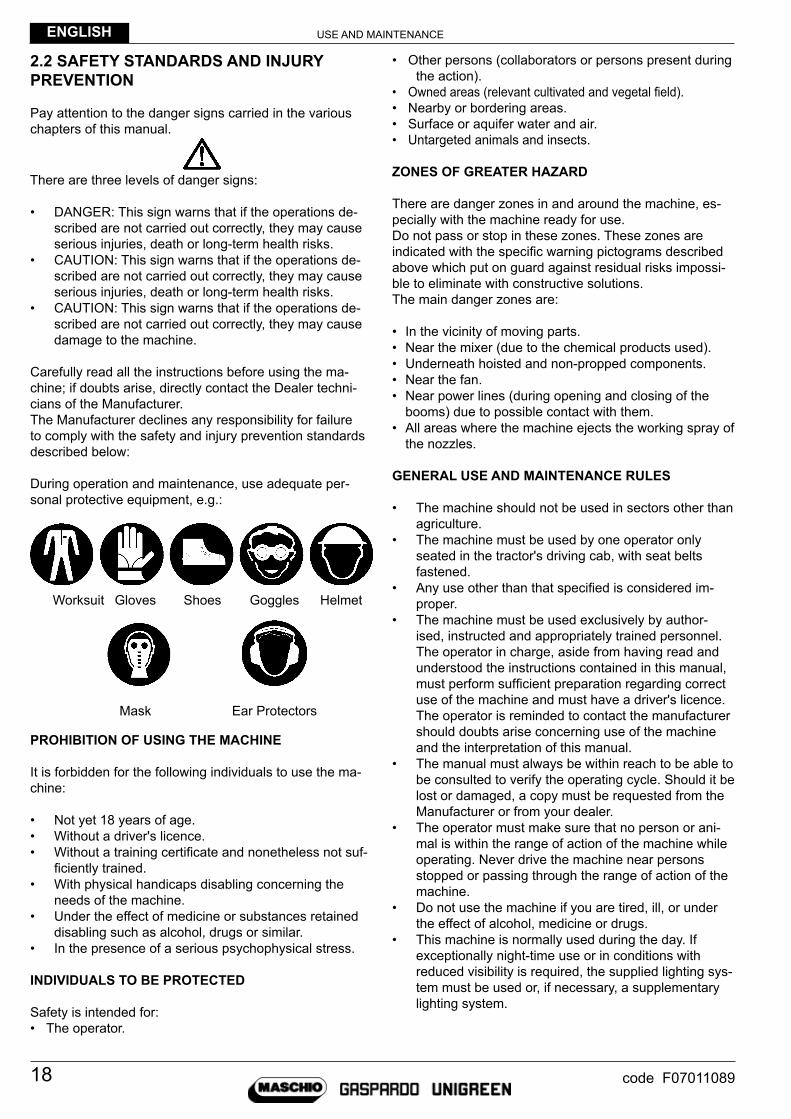
During operation and maintenance, use adequate per-sonal protective equipment, e.g.:
Worksuit Gloves shoes Goggles helmet
mask Ear protectors
PROHIBITION OF USING THE MACHINE
it is forbidden for the following individuals to use the ma-chine:
• Not yet 18 years of age.• Without a driver's licence.• Without a training certificate and nonetheless not suf-
ficiently trained.• With physical handicaps disabling concerning the
needs of the machine.• under the effect of medicine or substances retained
disabling such as alcohol, drugs or similar.• in the presence of a serious psychophysical stress.
INDIVIDUALS TO BE PROTECTED
safety is intended for:• the operator.
• other persons (collaborators or persons present during the action).
• Owned areas (relevant cultivated and vegetal field).• Nearby or bordering areas.• surface or aquifer water and air.• untargeted animals and insects.
ZONES OF GREATER HAZARD
There are danger zones in and around the machine, es-pecially with the machine ready for use.Do not pass or stop in these zones. These zones are indicated with the specific warning pictograms described above which put on guard against residual risks impossi-ble to eliminate with constructive solutions.The main danger zones are:
• In the vicinity of moving parts.• Near the mixer (due to the chemical products used).• Underneath hoisted and non-propped components.• Near the fan.• Near power lines (during opening and closing of the
booms) due to possible contact with them.• All areas where the machine ejects the working spray of
the nozzles.
GENERAL USE AND MAINTENANCE RULES
• the machine should not be used in sectors other than agriculture.
• the machine must be used by one operator only seated in the tractor's driving cab, with seat belts fastened.
• Any use other than that specified is considered im-proper.
• the machine must be used exclusively by author-ised, instructed and appropriately trained personnel. the operator in charge, aside from having read and understood the instructions contained in this manual, must perform sufficient preparation regarding correct use of the machine and must have a driver's licence. the operator is reminded to contact the manufacturer should doubts arise concerning use of the machine and the interpretation of this manual.
• the manual must always be within reach to be able to be consulted to verify the operating cycle. should it be lost or damaged, a copy must be requested from the manufacturer or from your dealer.
• the operator must make sure that no person or ani-mal is within the range of action of the machine while operating. Never drive the machine near persons stopped or passing through the range of action of the machine.
• Do not use the machine if you are tired, ill, or under the effect of alcohol, medicine or drugs.
• this machine is normally used during the day. if exceptionally night-time use or in conditions with reduced visibility is required, the supplied lighting sys-tem must be used or, if necessary, a supplementary lighting system.

USE AND MAINTENANCE ENGLISH
19code F07011089
• Any arbitrary modification made to this machine releases the manufacturer from all liability regarding damage or injuries which can result to operators, third parties or objects.
• Carefully check the machine every time you activate it.
• the manufacturer cannot foresee all reasonably unforeseeable misuse which can entail a potential hazard.
• the signs applied to the machine supply a series of important indications: complying with them is for your safety.
• make sure that all the safety pictograms are legible. Clean them and, if needed, replace them with new labels.
• Before using the machine, make sure that all the safety devices are placed properly in their position and are in good condition; should the protections be faulty or damaged, replace them immediately.
• Before getting off the machine and before any main-tenance operation, engage the parking brake, switch the engine off and remove the ignition key from the dashboard of the tractor.
• personnel must use the safety measures and person-al protective equipment during use and maintenance of the vehicle.
• the machine operator is recommended not to wear clothing which can get caught, such as sleeves with wide cuffs, fluttering clothing or fabric tails.
• the operator must be equipped with a suitable face-mask to protect the respiratory tract during prepara-tion of the product or when leaving the driver's cab during the operating phases.
• During use, the operator must have sufficient visibility of the work areas considered dangerous. therefore the mirrors on the tractor must be kept clean and in ideal conditions.
• the machine must not be left unattended with the en-gine of the tractor running or the ignition key inserted.
• Keep the machine clear of foreign materials (debris, tools, various objects), which could damage function-ing or harm the operator.
• use the parking brake when stopping the machine on slopes.
• Do not work on muddy, sandy or loose soil.• Check the state of wear of the hydraulic tubes and, if
deteriorated, have them completely replaced.• Do not use controls or hoses as grips; these compo-
nents are movable and do not offer a stable support.• Any modifications of the machine could cause safety
problems. in that case, the user is the sole responsi-ble in case of accidents.
• it is strictly forbidden to remove or tamper with safety devices.
• make sure that the safety pictograms are in good conditions. if the pictograms are deteriorated, they must be replaced with other originals requested from the manufacturer and placed in the position indicated by the use and maintenance manual.
• When driving on public roads, make sure no chemical product is loaded in the tank.
• Before driving on public roads, place the machine in
the transport position, according to that arranged by the manufacturer and described in this manual.
• it is strictly forbidden to transport persons on the machine.
• it is strictly forbidden to use the booms as a support to access other parts of the machine.
• Regularly check the pressure of the tyres and always adhere to the inflation pressure provided in table 17 of this manual.
• pay attention to the risk of unintentional contact of machine parts with overhead high-voltage lines.
• turn the vehicle cautiously, taking into account the overhang, length, height, centre of gravity and weight of the machine.
• Absolutely avoid working in the immediate vicinity of escarpments or overhanging areas making the tyre hold unstable.
• it is absolutely forbidden to stand on access devices while the machine is moving.
• Check the condition of the tubes and fittings daily. If they show clear signs of ageing (cracks, cuts) or me-chanical damage (deformation, bottlenecks) replace them immediately.
• periodically check tightening of all bolts and nuts.• Always keep the nozzles of the spraying boom in
good condition, periodically checking that they have no cracks, obstructions or worn parts.
• Do not keep the tractor engine running in closed premises without a suitable ventilation system capa-ble of disposing of harmful exhaust gases concen-trated in the air.
• Avoid prolonged and repeated contact of skin with fuels, lubricants or fluids as they could create skin disorders or other syndromes.
• Do not swallow fuels, lubricants or fluids. In case of ingestion or accidental contact with the eyes, wash the concerned part with water and immediately con-tact a physician reporting the label of the concerned product.
PHYTOSANITARY PRODUCTS
• spraying is a delicate operation entailing considerable risks of contamination of persons, animals and the surrounding environment. it is very important to take care of functionality of all components of the trailed machine.
• the operator is always the subject most exposed to the chemical products used and must work using all the precautions necessary for his own safety.

USE AND MAINTENANCEENGLISH
20 code F07011089
• Before using the phytosanitary products, carefully read all the instructions for use provided in this manual and on the container of the agrochemical you intend on using, paying special attention to:
• Level of toxicity for the operator.• Level of toxicity for the environment and crops.• Application timetable.• Correct dosage per hectare.• Correct dilution.• Correct agitation.
the following is a list of the main precautions which the operator must take when using these products:• handle the products with care. it is mandatory to wear
all the required ppE: acid resistant rubber gloves, pu-rifying goggles/facemasks or helmets, worksuits made of water-repellent fabrics or tYVEK, rubber boots or similar.
• Careful storage of the chemical products in appropri-ately protected areas arranged for this purpose, with access prohibited for unauthorised personnel and children.
• pay attention to storage regarding the type of packing and the product: if powders, be careful of humidity by placing the products high above the ground; if liquids, do not place them above the powders.
• Containers which are no longer sealed must be put inside of specific watertight containers to keep them from spilling.
• there should be adequate ppE and absorbent mats near the warehouse.
• in case of contact with eyes or ingestion of chemi-cal products or product mixture, consult a physician bringing the label of the swallowed product and/or the safety data sheet.
• Do not smoke, drink or eat while preparing or distrib-uting the mixture or near or inside the treated areas.
• DO NOT ENTER THE TANK: residues of the chemi-cal product can cause poisoning and suffocation.
• it is not allowed to drive on the road with tanks full of water or phytoiatric mixture.
• it is ill-advised to transport containers of concentrated phytochemicals on the machine, especially on public roads. if necessary, these containers must be ap-propriately sealed and inserted in specific watertight containers, keeping the packages from falling, spilling and breaking.
• Replace outside air supply filters with active carbon fil-ters, following the indications of the manufacturer and replace them when they expire, periodically checking their efficiency.
• make sure that the chemical substances to be used are compatible with the materials the machine is made of and pay close attention when handling con-centrated products.
• prepare the phytochemical mixtures knowing the ex-tension of the area to be treated (ha) and establishing the exact volumes (total litres and l/ha) to be distrib-uted, paying close attention while handling concen-trated products.
• Do not mix products whose physical, chemical and
biological compatibility you are not sure of.• Make sure the mixture does not overflow while filling it
and pay attention not to exceed the nominal capacity of the tank.
• it is recommended to display on the machine the type and amount (percentage) of diluted agrochemicals in the tanks; this could be useful in case of an accident.
• use appropriate (low) pressures to avoid generating droplets which are too small producing drifting.
• The correct size of the nozzles contributes to con-trolling the drift, affording correct control over work pressure.
• implement correct stirring of the mixture in order to have a proper concentration during the whole treat-ment.
• Wash the phytochemical containers carefully using the supplied accessories and rinsing several times with clean water.
• Collect the washed containers and send them to specific collection facilities, never abandon them in the environment and do not use them for any other purpose. it is a good idea to make the container unus-able by making a hole at the bottom.
• perform the treatment while respecting the safety distances from sensitive zones such as: homes, waterways, roads, sport facilities, public greenery or public paths. the operator must also stop work when persons or animals come within the range of action of the machine or the distance is not sufficient to avoid the risk of contamination.
• Always keep the mixing tank lid closed during transfer and spraying.
• Verify the presence of specific areas which regulate treatment methods, in particular for rows at the border of the field near sensitive zones (in some places, there is the obligation of treating the last row by hand).
• Do not treat in the presence of adverse weather con-ditions.
• it is important to operate in proper atmospheric condi-tions and to have information concerning the weather conditions during the entire period of application.
• Adjust the mixture flow, centring the target zone. Ap-proach the emission point as close to the target as possible in order to limit releasing the mixture into the environment.
• Always verify the presence of clean water in the spe-cific tank before each work session and the last fill up of the day.
• Dilute the volume of technical residues by at least 10 times and spread on a part of the field which is un-dertreated or capable of absorbing the supplied liquid without undergoing any harm.
• Never leave chemical substances in the tank for over a few hours.
• in case of using liquid fertilisers or particularly ag-gressive products protect the machine with suitable products and wash with care after each use.
• Never unload the residues at the same point.• the uncontrolled drainage of diluted residues in wa-

USE AND MAINTENANCE ENGLISH
21code F07011089
fig. 5
fig. 6
U32150961Misura 120x60 mm
Adesivo da applicare su polietilene
U32150961
terways, sewers and in public areas is strictly forbid-den.
• it is mandatory to wash the inside and outside of the machine. We recommend performing inside and outside washing directly in the field, far from sensitive areas to avoid possibly contaminating aquifers and even surface waters; secondarily perform washing in an area equipped with a waste-water collection tank, then disposed of according to regulations in force or in an area with appropriately implemented organic purification.
• Before reusing them, carefully wash clothing which came into contact with the chemical mixture, either pure or diluted.
• Do not use the machine without clean water in the hand washing tank or if it is not completely full and periodically renew the hand washing water.
OPERATOR FALL
to minimise risk probability, strictly comply with the follow-ing instructions:• it is forbidden to climb on the machine to perform any
operation.• Pay attention to the slipping hazard especially with
damp or wet surface or when your shoes are muddy. use the suitable mixer to load products. When using the ladder, make use of the suitable hand holds, rails etc. (fig. 5).
• to load the pesticides you must use the suitable lad-der and stand on the suitable platform (without pre-mixer).
MACHINE BREAKAGE
to minimise risk probability, strictly comply with the follow-ing instructions:• Do not leave chemicals inside the tank longer than
necessary (a few hours at most).• Check and frequently clean the nozzles and hydraulic
circuit (especially filters) to prevent them from clog-ging and affecting distribution efficiency.
• All electrical devices have been designed for wet and hard environments. however they must be protected from any possible additional damage. the cables must never be forcefully bent or looped. When the machine is unused they must be stored away from light and rain.
• Do not modify factory adjustments and parameters unless you are certain it is necessary.
• During boom movement pay attention not to hit the wheels of the machine. Excessive lowering of the booms would cause a collision between tyre and boom causing serious problems to the machine (fig.6).
• should it be necessary act according to the instruc-tions given thereafter in this manual or other attached manual.

USE AND MAINTENANCEENGLISH
22 code F07011089
fig. 7
ELECTROCUTION HAZARD
Do not operate underneath or close to electrical lines (fig. 7).in the event of unauthorised approaching or contact with live power lines there can be serious injury to the entire body with the risk of death.Pay the utmost attention to aerial electrical lines; at certain moments of arms opening-closing and when us-ing variable configuration the total height of the machine increases considerably. Keep at a sufficient distance from power lines.
RATED VOLTAGE SAFETY DISTANCE FROM POWER LINES
up to 1 KV 3.28 ft (1m)
over 1 up to 110 KV 6.56 ft (2m)
over 110 up to 220 KV 9.84 ft (3m)
over 220 up to 380 KV 13.12 ft (4m)
FIRE PREVENTION MEASURES
the machine is built using many petroleum derivative materials; furthermore the presence of various types of oils and chemical product residues make the machine potentially flammable.
ATTENTIONWe recommend keeping a fire extinguisher of suf-ficient capacity on board the tractor and to have it checked periodically by qualified personnel. The use of the hand fire extinguisher is reserved to trained personnel.
• it is recommended that the personnel in charge of the vehicle be aware of the primary intervention tech-niques in the event of fire.
• All fuels and most lubricants and hydraulic fluids are flammable.
• Do not smoke while refuelling or topping up the fluid level, do not refuel near naked flames and do not transfer the fuel.
• switch the tractor engine off before refuelling, do not refuel in closed and/or insufficiently ventilated areas.
• Before starting the engine, make sure there are no leaks or residues of fuels/lubricants/fluids which could cause small fires.
• Short circuits can cause fires. Periodically check the conditions of the battery terminals, cables and electric equipment.
• Do not store flammable substances in unsuitable plac-es, do not perforate or burn pressurised containers or spray cans, do not accumulate materials soaked in flammable substances.
• pay attention where rags or replaced material which can contain flammable residues are put.
• Periodically clean the machine with specific equip-ment (high pressure water cleaner or compressed air) to reduce the risk of self-combustion to a minimum.
table 2

USE AND MAINTENANCE ENGLISH
23code F07011089
550 mm
4
3
2
5
1
fig. 8
fig. 9
fig. 10
• Use appropriate fire extinguishing means: carbon dioxide, foam, chemical powder.
• Do not use water jets. only use water jets to cool off surfaces exposed to the fire.
• Never use petrol, solvents or flammable or toxic fluids to clean mechanical parts: use approved commercial non-toxic and non-flammable solvents.
• Do not perform welds near tanks, pipes, canisters, electric cables or flammable materials in general.
• When performing welding, protect flammable parts and your eyes with appropriate shields.
• Clean the machine completely at least once a week.
SAFETY DISTANCE FROM THE PTO SHAFT
ATTENTIONIt is forbidden to move within 550 mm from the PTO shaft (drive shaft) with the tractor in motion and PTO engaged (Fig.8) to perform operations on:• Service valves.• Filters in general.• Cocks.• Pump oil tank• Drawbar clearance adjustment etc...These adjustments (if near the PTO shaft) must strictly be performed with the tractor engine off and ignition key removed.
PROTECTION AND SAFETY DEVICES FITTED ON THE MACHINE
• Grooved shaft protection cap on pump (1).• Railing (2).• Machine movement warning buzzer (3) (where pro-
vided).• Wheel locking wedges (4), if machine is approved.• parking brake (optional).• Lock valves on hydraulic cylinders.• maximum pump pressure safety valve (5)
PERSONNEL QUALIFICATIONS AND DUTIES
ATTENTIONOnly authorised and adequately instructed personnel, whose health condition is such as to ensure they are able to regularly perform their activities, are allowed to use the machine.
• Exposed person: any person wholly or partially in a danger zone.
• Hazardous area: any area within and/or around machinery in which an exposed person is subject to a risk to their health and safety.
• operator: performs ordinary service duties, required for machine operation: control actuation, skilled in operative cycle, cleaning surfaces and acting in the event of malfunctioning. in normal production, the operator shall act with all protections enabled. the personnel in charge of operating the machine, must possess - or acquire through adequate training and

USE AND MAINTENANCEENGLISH
24 code F07011089
instruction - the requisites set out below, as well as being aware of this manual and all safety-related information. the requisites are:
– General and technical culture at a sufficient level to understand the contents of the manual and interpret correctly figures, drawings and diagrams.
- Knowledge of the main rules of hygiene, accident protection, technology and first aid. - Knowledge of behaviour in the event of an emergency, where to obtain personal protection equipment and how to
use it correctly. - possessing regular authorisation to the purchase of plant protection products.• manufacturer's technician: the personnel of the manufacturing company or other personnel authorised by the same
who perform complex activities for installation, set-up, repair and, upon request, training the personnel in charge of operating the machine.
• mechanical maintenance technician: is the person who is a direct employee of the user or manufacturer, at any event adequately trained, and performs ordinary and extraordinary maintenance on the machine and reports the results on suitable registers.
• Electrical maintenance technician: skilled technical personnel, able to operate the machine in normal conditions, to service electrical parts, to perform all necessary adjustments, maintenance and repairs; they are able to operate on live parts.
• personnel in charge of handling and transport: personnel who have received adequate instruction on the use of lift-ing and handling devices.
2.3 STANDARDS OF REFERENCE
We declare, under our responsibility, that the machine complies with the health and safety requirements set forth by the following European Directives:
• MACHINERY DIRECTIVE 2006/42 EC.• 204/108/CE Electromagnetic Compatibility.• 2009/127/CE October 2009: machine for pesticide application
The following technical specifications have been used for adapting the machine:
• UNI EN ISO 16119-1/2013• UNI EN ISO 16119-2/2013• UNI EN ISO 4254-1/2010• UNI EN ISO 4254-6/2010• EN ISO 12100-2010• CEI EN 60204-1/2006• ISO 11684:1995• ISO 3767-2/2008

USE AND MAINTENANCE ENGLISH
25code F07011089
fig. 11
fig. 12
fig. 13
fig. 14
fig. 15
3.0 INFORMATION REGARDING THE MACHINE
3.1 INTENDED USE
the machine has been designed exclusively for the distri-bution of pesticides and plant protection products in differ-ent configurations:• In open field by horizontal, generally hydraulic weed-
killing boom with or without air sleeve assistance.• For scattered or thinned plants by hand gun or other
dedicated accessory.the machines are divided into the following models:• C (carriage) with VERTICAL boom lifting (Fig.11).• P with PARALLELOGRAM boom lifting (Fig.12).• R with PARALLELOGRAM boom lifting but less equipped
(fig.13).• E like model R but with VERTICAL lifting (Fig.14).• S with PARALLELOGRAM boom lifting, same equipment
as model p and axle with hYDRo-pNEumAtiC sus-pENsioNs (fig.15).
the purpose of these machines is to atomise the active mixture in aqueous solution and convey it to the crop to be treated through suitable pressure nozzles or with the aid of a pressurised air draft. in models with air generation, pul-verisation is assisted by an air flow produced by a fan, con-veyed in suitable apparatuses that accompany the droplets on the target area to be treated. This flow of air improves penetration in the leaf canopy and protects from the action of the wind, limiting drift. the machine might not be suited for work in areas subject to acoustic restrictions; in which case refer to the council regulations concerning times and allowed sound emissions.the machine has been designed and constructed to oper-ate outdoors and in agricultural areas, hence its perfor-mance is not conditioned by the weather. however, the weather interferes with treatment of the vegetation through atomised active mixtures
ATTENTIONOnly models approved for road circulation (Italy) may circulate on public roads (see chapter 4.0 “HANDLING AND TRANSPORT”).
ATTENTIONAny use of the machine different than that indicated above must be considered unauthorised and danger-ous. The machine has been designed for the distribu-tion of chemicals potentially hazardous for man and environment. Pay the utmost attention in all operative stages in order to prevent any dispersal of the product.
ATTENTIONThe manufacturer is not responsible for the damage caused by incorrect assessment of the place of move-ment or use.
Campo C / Sirio
Campo P / Pompeo P
Campo R
Campo S / Pompeo S
Campo E

USE AND MAINTENANCEENGLISH
26 code F07011089
1
1
2
3
2
3
4
4
fig. 16
fig. 17
3.2 DESCRIPTION AND OVERALL DIMENSIONS
CAmpo/siRio-pompEo 22-32 sprayers consist of a central frame, two wheels, the pump, the distributor and most of the hydraulic, water and electrical circuits. A drawbar is connected to the central frame to fix the machine to the tractor and a rear lifting system to fix the entire boom unit.the following tables and pictures describe the machine's overall dimensions:
tEChNiCAL DAtA
DEsCRiptioN Campo 22 Campo 32
Depth 17.06ft (5,20m) 21.33ft (6,50m)
max width on road 8.37ft (2,55m) 8.37ft (2,55m)Max width on field with open booms 91.86ft (28m) 91.86ft (28m)Max height (depending on tyre size) 10.50ft (3,2m) 10.99ft (3,35m)
table 3

USE AND MAINTENANCE ENGLISH
27code F07011089
9
25
262728
28
27
26
252120
1
19
29
35
224 32 33 36
34
30
91223141810
16
61745
3
815
13117
22
fig. 18
fig. 19
3.3 TECHNICAL DATA AND IDENTIFICATION OF THE COMPONENTS
The positions of the essential machine parts are highlighted in the following figures; see the following chapters for their detailed description.
the machine consists of: 1) main tank (capacity equal to 634.01 or 845.35gal). 2) side booms. 3) platform for tank hatch access. 4) Ladder for platform access. 5) Drawbar. 6) machine support foot. 7) indicator of liquid level in the tank. 8) pump. 9) sensor to detect advancement speed (machines with
computer). 10) Circuit washing tank emptying cap. 11) Coupling to load the tank from external source by
means of system pump. 12) premixer (capacity 7.93gal). 13) system washing tank (capacity 79.25gal). 14) Water pressure gauge. 15) hydraulic oil tank (optional). 16) hand washing tap. 17) maximum pressure regulator.
18) Suction filter. 19) Version C-p-s machine control panel. 20) Version R-E machine controls. 21) hand washing tank (capacity 3.96gal). 22) flow meter (machines with computer). 23) main tank discharge cock. 24) tank hatch. 25) Volume control valve (proportional). 26) main control valve. 27) maximum water pressure regulator. 28) Delivery filter. 29) Tank washing nozzle. 30) Variable configuration cylinder (if any). 31) Electronic computer board (present inside the box,
if any). 32) boom lifting cylinder (versions C-E). 33) Boom section valves. 34) Light bar (if any). 35) Venturi pipe stirrer. 36) Electro-hydraulic distributor block (if any).

USE AND MAINTENANCEENGLISH
28 code F07011089
Tables 15-16 “allowed outfittings” have the purpose of identifying the purchased version and highlight the base outfitting and all possible available complementing outfittings (optional) - see tables 15-16 “ALLOWED OUTFITTINGS” on page 98-99-100-101.It is also possible to identify other allowed outfittings or other versions which might address new needs in the future.
ATTENTIONThe outfitting defined in the allowed outfittings table (table 15-16 page 98-99-100-101) is to be considered bind-ing for the validity of the declaration of conformity.Different matchings of base and optional components are to be deemed as unsafe and thus outside the war-ranty or Manufacturer's liability.The same holds true for outfittings with non original components or accessories.
the following table provides the main technical data of the machine.
TECHNICAL DATA
DEsCRiptioN Campo 22 Campo 32
tank capacity 634.01 gal 845.35 gal
hand washing tank capacity 3.96 gal 3.96 gal
system washing tank capacity 79.25 gal 79.25 gal
foam marker tank capacity (if any) 5.81 gal 5.81 gal
premixer tank capacity 7.93 gal 7.93 gal
independent air sleeve/pump hydraulic oil tank capacity 13.20 / 3.70gal 13.20 / 3.70gal
unladen weight with boom 5599.74 lb 7672.08 lb
full weight with boom 11508.12 lb 15300.06 lb
Limit mass on eye 1918.02 lb 3417.16 lb
tractor power 70 hp min 70 hp min
pto Rotation (max) 540 rpm. 540 rpm.
Pump flow rate 64.72-105.67 gal/min.
64.72-105.67 gal/min.
pump pressure 14.50 psi 14.50 psi
the machines have different types of metals with or without surface protection, according to their resistance to oxidis-ing. these protections can be:
• Steel in general: Painting, Hot-dip galvanisation, Cold galvanisation, Chrome plating.• Aluminium: Painting, Plasticising, Galvanic oxidisation.• Brass: Nickel plating.• Stainless steel.
the following catalogued materials are also used for machine parts:
• Tanks: High density polyethylene, Stainless steel, Hot-dip galvanised steel.• Fittings: Polypropylene, Nylon with fibreglass, PVC, Brass.• Tubes and gaskets: Rubber mixtures with fabric inserts, plasticised PVC, NBR, Viton.• Tyres.• Petroleum derivative lubricants.
table 4

USE AND MAINTENANCE ENGLISH
29code F07011089
fig. 20 fig. 21
the use of aggressive chemical products for metals in general and for zinc requires a suitable superficial pro-tection of the different exposed parts in contact with the aggressive chemical mixtures. the following are known to be aggressive:
• Nitrogen liquid fertilisers in general.• Foliar and other fertilisers.• Copper hydroxide and similar products.• Salt spray near the sea.
Exposure to these products imposes painting all parts.
ATTENTIONThe use of suspended liquid fertiliser is forbidden while its use in the solution is possible, after having informed the Manufacturer when placing the order and anyway replacing some parts.
3.4 MAIN EQUIPMENT
the machine consists of three families of systems:• Hydraulic system.• Electric system.• Water system for spraying.
3.4.1 HYDRAULIC SYSTEM
the hydraulic system is powered directly by the tractor.Tractors are fitted with hydraulic couplers which are able to convey several tens of litres per minute of oil (fig. 20). The distributors of our machines are fitted with line throttle valves (fixed or adjustable) suitable to assure consistent hydraulic cylinder speeds should the oil flow rate be in excess.however, the following must be available on the tractor:• At least 5.28gal/min (20 l/min) at 2320.60psi (160bar)
for the hydraulic unit moving the hydraulic boom cylinders.\
• At least 11.89gal/min (45 l/min) at 2320.60psi (160bar) for the hydraulic actuation of the hydraulic filling pump (optional).
• maximum operating pressure 2610.68psi (180bar).• hydraulic oil for the machine: sAE 90 normally suit-
able for combined hydraulic system and drive circuits of all the most common brands of tractors.
the machines that require hydraulic coupling to actuate the sprayer booms, are fitted with “Push- Pull” 1/2” HA series iso7241-1A quick connection male coupling halves (fig. 21).the number of pairs of hydraulic couplers needed de-pends on the type of boom and the selected hydraulic system.the following options are normally possible:a) one pair only of quick couplings with snap lever which
feeds an independent manual or electrical distributor for all boom hydraulic functions.
b) one pair of quick couplings plus other pairs of hydraulic sustained action couplers for additional services such as hydraulic foot, shock absorber adjustment, other.
piping connection takes place by pushing the coupling
into the tractor's hydraulic coupler; pay attention to:• Lower any implements connected to the tractor's lifter.• Accurately clean the two parts to be connected.• turn off the tractor's motor, ensure the pressure is
down on the tractor and on the machine, then pro-ceed to coupling.
ATTENTIONThe type of hydraulic cylinders used are “Simple Ef-fect” and “Double Effect”. Refer to the tractor's use and maintenance manual.
Comply with colour-based pipe coupling.Connect the quick delivery and discharge coupling in the respective seats complying with the flows:
• RED = (p) = delivery• CYAN = (t) = discharge
there is no known damage caused by the pressure of tractors' systems to the hydraulic circuit of weed control machines, however, one must ascertain the tractor's flow and pressure specifications and adjust any flow dividers, throttle valves and other valves, especially on first use.
the piping used in pressure ducting have suitable fea-tures to withstand the calculated operating pressures.
ATTENTIONDo not operate on pressurised pipes.
Working pressure operating temperature
max 2610.68psi (180bar) from 50 to 158°f (da 10 a 70°C)
table 5

USE AND MAINTENANCEENGLISH
30 code F07011089
"Cigarette lighter" type power socket
3-pole power socket
2-pole power socket
7-pole power socket
10A Fuse
25A Fuse
10A Fuse
5A Fuse
fig. 22
fig. 23
fig. 24
fig. 25
3.4.2 ELECTRIC SYSTEM
The machine may be fitted with electrical components that require supplying from the electrical system of the tractor at 12 V (Volt). in order not to damage the system, one must ensure the power is taken directly from the battery (and not from the starter motor).
ATTENTIONFor electrical pin connection, contact a skilled techni-cian.
Depending on machine models one or more of the sock-ets shown here may be necessary.for further details see chapter 11.4.1.

USE AND MAINTENANCE ENGLISH
31code F07011089
3.4.3 WATER SYSTEM FOR TREATMENT
the main elements that characterise the water system are as follows:
DEsCRiptioN Campo 22 Campo 32
main tank 634.01 gal 845.35 gal
hand washer tank 3.96 gal 3.96 galsystem washer tank 79.25 gal 79.25 galfoam marker tank (if any) 5.81 gal 5.81 gal
pre-mixer tank 7.93 gal 7.93 gal
up to 7 section valves and a simple product delivery and return circuit are present in the booms.Read paragraph 6.5 for a detailed description of the spraying system.
3.5 TYRES
Depending on the main use of the sprayer, tyre size may be useful to improve machine lift on moist or worked soil, or minimise trampling of well established crops.Table 17 on page 102 shows the various types of tyres that may be fitted and relevant technical data.
ATTENTIONThe provided data is obtained from trade catalogues.
An important datum is the rolling circumference CR, used for the teeJet spraying computer settings.When inflating the tyres, remain to the side of the tyre's shoulder.for further details see chapters 10.5 - 11.4.5.
3.6 NOISE LEVEL
There is no specific procedure to measure noise on this machine; therefore, operative conditions have been adopted, which are generally valid for all agricultural machines, described in standard uNi EN iso 4254-1:2010.The test has been performed on a large free and reflecting surface, with vehicle stopped, with the machine operating idle, at top speed and operator seated in the tractor cabin.the following values have been detected:for atomisers with pump and hydraulic system only:• sound power level = 106dBA• sound pressure level in operator position = 91.4dBAfor atomisers with air sleeve:• sound power level = 114.8dBA• sound pressure level in operator position = 97dBA
ATTENTIONThe indicated noise values are conventional emission levels and do not necessarily represent safe working levels.Although there exists a relation between emission levels and exposure levels, this cannot be used in a reliable manner to establish whether additional precautions are required.The factors that determine the real exposure level of workers include the length of the exposure, the features of the work place (acoustic absorption coefficient of the soil and other surfaces, others sources of noise etc.), the fact of working in motion and especially whether the cab is present or not.Furthermore, admissible exposure levels may vary from country to country.However, this information allow the user to perform better danger and risk assessment.If the tractor is not equipped with a cab, operators in charge must wear hearing protection equipment (PPE). If, on the other hand the tractor is equipped with a cab, it is the user's responsibility to have its effectiveness checked and establish whether PPE is required.CAUTION! With earmuffs alarm signals are not perceived and caution is necessary.
table 6

USE AND MAINTENANCEENGLISH
32 code F07011089
3.7 VIBRATION LEVEL
In conditions of operation compliant with correct use indications, vibrations are not such as to give rise to hazardous situations.
3.8 CONTROLS TO BE CARRIED OUT UPON RECEPTION OF THE MACHINE
When receiving the machine, make sure that all its parts are intact.should there be damaged parts, immediately inform your Dealer or the manufacturer or inform mAsChio GAspARDo s.p.A. directly.When the machine is delivered, expressly request the following:
• That the machine be delivered fully mounted (this procedure is necessary as the machine could be shipped partially disassembled for reasons of bulk).
• That the machine be put on the field in your presence, in order to supply the information necessary to correctly use it.
3.9 FIRST USE OR PUTTING BACK INTO SERVICE AFTER A LONG IDLE PERIOD
Before using the machine for the first time, or after a long idle period, you must do the following:
• Check that the machine shows no damage.• Check that every part of the machine is mounted correctly.• Check that the mechanical parts are in good condition and not rusted.• Check level of liquids in the oil-hydraulic system.• Check the tyres for wear.• Check that the lights and electric system work properly.• Thoroughly grease all movable parts, including the drives and mechanical joints (see chapter 11.3.6).• Check that there is no oil leakage from fittings or piping.• Check that all the guards are positioned correctly.• Check the electrolyte level in the tractor battery and the charging level.• Check that the filters of the hydraulic circuit and inside the tanks are clean and clear of residue.• Check that the connections are fitted correctly, following the basic diagram.• Check that the tube clamps are tightened correctly, like all fittings and connections.• Check that the fan - if any - is free to spin and that the housing is not deformed by blows suffered during transport.• Check and if needed top up the pump oil level.• Make sure that the protective devices are present and working.• Check pump membranes condition.• Check that all nozzles are in good condition, without obvious signs of wear and scales.• Check the condition of all flexible hoses and replace them if necessary.• Check tightening of all machine bolts, especially those tightening the wheels.
3.10 STORAGE - PUTTING IN GARAGE
if the machine is immobilised for long periods, it must be stored in a place sheltered from atmospheric agents and pro-tected to avoid being damaged.make sure that the storage temperature is between 32°f and 104°f (0°C and 40°C). Do not set the machine on soft or excessively sloped ground. should it be deemed necessary, place the wedges (chocks) supplied underneath the points of contact with the ground for better distribution of the weight and to prevent dangerous sinking.the machine is designed to be parked safely on compact ground with up to 0.15rad (8.5°) slopes.to prepare the machine to be put away, the tank and the hydraulic circuit must be cleaned thoroughly using the same procedure as at the end of treatment.You must also:• Thoroughly wash and clean the machine, including the spraying system.• Completely empty the hydraulic circuit to avoid damage caused by freezing.• Completely empty the spraying system.• Introduce a water and antifreeze mixture in the spraying circuit to protect not only the pump, but all the components in
contact with the liquid as well, namely control units, nozzle holders and filters (see the procedure for introducing the antifreeze liquid, paragraph 10.6).

USE AND MAINTENANCE ENGLISH
33code F07011089
• Remove and clean the filters and nozzles which must be kept in an area protected against weathering.• Empty the diaphragm pumps by removing the specific plug.• Unscrew the mixer drain pipe.• Remove all air and water filters.• Check and grease all movable metal parts and unpainted parts, paying special attention to the greasing points on the
boom.• Repaint all surfaces which could rust, where necessary.• Disconnect the battery both with the battery cut-off key and by physically disconnecting the two poles.• Place the machine in a ventilated area, sheltered from rain and sunlight.
the procedures of some of the phases listed above will be described in detail in the next chapters.
3.11 DEMOLITION AND WASTE DISPOSAL
When scrapping the machine, it must be disposed of in adequate landfills, complying with current legislation.Before scrapping it, thoroughly clean the equipment, washing it inside and outside. Draining washing residue into the environment without precautions is forbidden as it pollutes the aquifers.Recover any used oils and dispose of them in specific collection facilities.
ATTENTIONWaste oil must be appropriately recovered and must not be released into the environment as, according to legal standards in force, it is classified as dangerous waste and as such must be brought to specific collection facilities.
To collect waste oil, it is mandatory to contact the “Consorzio Obbligatorio Oli Usati” [Mandatory Waste Oil Consortium].Before proceeding with scrapping, parts which can be recovered must be separated, in compliance with D.m. 5 febru-ary 1998. the following are special non-dangerous waste:• Ferrous materials, aluminium, stainless steel, copper.• Plastic materials.• Tyres and rubber in general.• Circuit boards.• Electric material.
3.11.1 GUIDELINES FOR SUITABLE TREATMENT OF WASTE
the correct management of special waste entails:
• Storage in suitable places, avoiding mixing dangerous with non-dangerous waste.• Transport and disposal/recovery of the same by authorised carriers and recipients.
transporting your own waste to authorised collection facilities is only permitted if registered at the National Register of Environmental managers.
3.11.2 WASTE OF ELECTRIC AND ELECTRONIC EQUIPMENT (WEEE)
With the Legislative Decree of 25 July 2005 n. 151, the italian Government transposed the directives of the European parliament regarding the waste of electric and electronic equipment (WEEE) (Directive 2002/95/EC and 2003/108/EC).in particular, the decree establishes measures and procedures aimed at:• preventing the production of WEEE.• promoting the reuse, recycling and other forms of recovery of WEEE, in order to reduce the amount to be disposed of.• Improving, under an environmental profile, the intervention of the individuals who participate in the lifecycle of this
equipment (manufacturers, distributors, consumers and operators directly involved in the treatment of WEEE).• Reducing the use of dangerous substances in electric and electronic equipment.
the decree lays down the limitation and elimination of some substances present in WEEE.the following are banned: lead, mercury, cadmium, hexavalent chromium, polybrominated biphenyls or polybrominated diphenyl ethers.

USE AND MAINTENANCEENGLISH
34 code F07011089
the machine was designed and built in compliance with this directive. the symbol above, representing a crossed-out wheeled waste bin, indicates the separate collection of the electric and electronic equipment of the machine.the user of this machine may contact the collection facilities established by the Local authorities or directly contact mAsChio GAspARDo s.p.A., or else ask the Dealer to withdraw it, in order to correctly dispose of the machine.
3.12 PROHIBITED USE
Any use other than the intended use is STRICTLY forbidden; in particular we call the attention to the prohibition of using the machine with the following products:
• All types of paints.• Solvents or thinners for all types of paints.• All types of fuels or lubricants.• All types of LPG or gases.• All types of flammable liquids.• Animal and human foodstuff liquids.• Liquids containing granules or consistent solids.• Mixtures of several chemical products incompatible with each other.• Particularly dense liquid or suspended fertilisers and/or with lumps.• Liquids warmer than 104°F (40°C).• All products not included in the specific use of the machine.
3.13 LIABILITY OF MASCHIO GASPARDO S.P.A. FOR ORGANIC DAMAGE
mAsChio GAspARDo s.p.A. does not respond for any organic damage caused by non-conforming use of the ma-chine.By non-conforming use we mean:
• Lack of training or incapability of the operator.• Failure to periodically calibrate and/or check operation of the equipment.• Incorrect interpretation or use of the phytochemical manufacturer's instructions carried on the label.• Error in preparing the mixture and/or reading or interpreting the nozzle dispensing tables.• Error in measuring the field or the advancement speed.• Use with adverse weather conditions and failure to control drifting.• Irregularity of treatment due to excessive speed (compared to the condition of the soil) or instability of the boom.• Failure to clean and wash the machine, with irregular operation and partial obstruction of the nozzles.• Periodical maintenance omitted.• Improper replacement of machine parts regarding measurement or type, such as for example filter cartridges, nozzle
dimensions and/or type, pressure gauges, etc.• Incorrect operation of accessories (original and/or non-original) fitted after the purchase.

USE AND MAINTENANCE ENGLISH
35code F07011089
Max 8.5°
fig. 26
fig. 27
4.0 HANDLING AND TRANSPORT
4.1 LIFTING THE MACHINE WITH ROPES
Before performing lifting of the machine, make sure it is placed on a flat and compacted surface.After that, stretch the belts and insert them in the points shown in Fig. 26, marked by specific stickers and start lifting in a slow and gradual manner. place the machine on flat and compacted soil, at a tilt not exceeding 0.15rad (8.5°) (fig. 27).
ATTENTIONEnsure the lifting equipment has a load capacity greater than the weight of the machine (see CE Plate).In machine transport, handling and placement stages pay attention to:• Danger of tipping components.• Danger of impact and crushing for people.It is advisable to check correct machine balancing until the machine is entirely lifted.Do not lift or manually handle the machine with liquid inside the tanks, as the weight is greater and the liquid inevitably shifts, changing the centre of gravity and causing dangerous and uncontrollable move-ments.Lifting must be carried out consistently (with no tears or pulses).Make sure there are no persons in dangerous areas.During lifting, the area surrounding the component is to be considered hazardous area.The manufacturer is not liable for damage attributable to the machine after delivery.
4.2 LOADING THE MACHINE ON A VEHICLE AND TRANSPORT ON PUBLIC ROAD
• Loading and unloading the machine on a vehicle always involve conditions of danger; pay the utmost attention throughout the entire operation.
• Perform loading and unloading on solid and level ground; keep a safe distance from the edges of ditches or from the road.
• Use ramps able to withstand the weight of the machine and of adequate width, placed with longitudinal axes parallel between them, perpendicular to the tail lift, and ensure they have a suitable centre distance to the road-way of the machine.
• Make sure the ramps are firmly anchored to the loading surface and have the same length.

USE AND MAINTENANCEENGLISH
36 code F07011089
RAMPS
WEDGES
Max 15°0.236rad
1
1
2
3
fig. 28
fig. 29
fig. 30
• Place the ramps at a maximum angle of 0.26rad (15°).• Make sure the ramps are free from traces of oil, grease,
soil and ice; remove any dirt from the machine's tyres too before starting loading.
• On the ramps, do not correct trajectory; should some changes be required, get off the ramps and search for the right trajectory.
• Check the transit gauge; height, width and weight of the vehicle including the machine must be compatible with the roads to be travelled, tunnels, underpasses, bridges, electrical and telephone lines, etc.
• Comply with the rules in force for required signals, the rules for speed and road traffic, require any permits, etc.
• Make sure the booms have been correctly closed and placed on the respective boom supports. make sure the machine does not exceed 13.12ft (4 metres) of maxi-mum height.
ATTENTIONBefore loading the machine on the vehicle, operate as follows:
• Make sure there are no residual liquids inside the tank (empty tank).
• After loading the machine, it must be secired with the anchoring ropes (1) and locked by running the ropes between the axle (2), finally the wheels must be locked by means of suitable locking wedges (3), all at the ex-pense and under the responsibility of the haulier.
• Fastening of the machine on the loading floor of the transport vehicle equally falls under the responsibility of the haulier (the obligation to assure the immovability of the load is clearly set out in the highway Code).
4.3 MACHINE TRANSFER IN THE FIELD
Before performing machine transfers you must:• make sure there are no persons or things near the
machine before commissioning it and during use.• put all moving machine components in the transport
position, locking them with the suitable fastenings.• Lock control levers, in order to prevent accidental
operation.• make sure the boom or other supply apparatuses fall
within the clearance gauge and are correctly folded away, supported and hooked to the supports.
• With regards to safe displacements and in operation, consider possible terrain slope and unevenness.
ATTENTIONIn the first phase of the machine's life there is a gen-eral adjustment of all mechanical parts and hydraulic connections. It is indispensable to check couplings (tightening and seal) with the utmost accuracy.

USE AND MAINTENANCE ENGLISH
37code F07011089
Before every working shift and before every transfer check:
• the effectiveness of actuation and safety devices.• Correct connection of the machine to the tractor.• Correct operation of the pto drive.• Correct connection of the feeding piping.• Correct air pressure of tyres and wear condition.• that the pins of wheels and axle are tightened se-
curely complying with the relevant tightening torques.• Working and cleaning of lights (if any).• presence of wedges (chocks) in the trailed machines
(if any).During the working shift check:• that the machine does not show obvious operation
defects.• should any faults be detected during use, they must
be removed and communicated to the next operator.
4.4 TRANSIT ON PUBLIC ROADS (ONLY FOR APPROVED MACHINES)
make sure the tractor used is suitable for road circulation and has the suitable features to trail the machine in use. the data to be checked is shown on the approval plate (see chapter 1.3).
ATTENTIONDuring transport on public roads strictly comply with the highway code, paying special attention in select-ing an adequate speed.
trailed machines may circulate on public roads (in italy) only if they are approved; you must check with your area dealer the correct couplings and use tractors in compli-ance with regulations currently in force.two types of road approval exist for trailed machines:• unladen (with no liquid in the tank).• Laden (with liquid, water only, in the tank), we would
like to remind you that it is forbidden to transport chemical mixtures on public roads.
the manufacturer's range includes unladen approval of most trailed models and, only for some, also laden ap-proval.Before driving on public roads, the machine must be registered at the Department of Motor Vehicles filing the "Declaration of conformity for type approved vehicle) sup-plied by the manufacturer.Check the suitability of the machine found on the specific plate and punching of the frame (see chapter 1.3) as well as the presence of the specific documents, chocks, reflec-tors and rear lights.the electrical light signal system is available in road set-up (but upon request also for private areas).
ATTENTIONit is obligatory to fit the vehicle with yellow or orange flashing light.
• Check the headlights, brake lights and indicators are working before driving on the roads.
• make sure the machine is closed so it falls within the tractor's gauge, since if it were open, the protrusion would involve a hazardous situation for any pedestri-ans or violent impact with solid objects along the road.
• the pto shaft must strictly be still.• Ensure the safety pin is inserted in the coupling pin of
the machine to the tractor.• Before turning onto a public road after driving on an
unsurfaced or dirty area, it is obligatory to accurately clean the tyres from any mud residues.
• the tractor speed shall have to be low and in any case adequate to the road surface you are travelling on, and speed must be reduced in bends.
• in the event of travelling on sloping roads, pay the utmost attention, since external conditions and fac-tors of various nature - e.g. wet, slippery surface etc. - might affect stability.
• it is strictly forbidden during transport of the machine to load other material onto it or carry other people; in any case there should be no other person than the driver on the tractor.
4.5 STEERING
The weight and configuration of the machine modify trac-tor's stability in bends. in particular, when negotiating bends with trailed ma-chines being transferred, with a narrow carriageway, the inertial thrust of the machine causes tilting hazard. This risk increases if the boom or sprayer apparatus is closed or in transport position. the presence of liquid in the tank contributes to reducing stability in bends.With unavoidable terrain unevenness and use of the steering drawbar never exceed the speed of 3.11mile/hour (5 km/h).Also consider any side protrusion of the machine with re-spect to the tractor and the possibility that the implement closes the bend more than the tractor.finally, the slope of the terrain contributes to increasing machine instability. Adapt the travelling speed to environ-mental conditions always and everywhere.

USE AND MAINTENANCEENGLISH
38 code F07011089
fig. 31
fig. 32
fig. 33
4.6 OPERATING LIMIT CONDITIONS
the machines are designed to work safely with slopes up to 0.15rad (8.5°) uphill, downhill and sideways.however, you must always take into account the fact that during transfers, when turning at the headland, with booms or sprayer apparatuses closed and narrow wheel base, the centre of gravity changes. this variation obliges to careful management of the equipment.When loading weight on the rear axle of the tractor (trailed machines with connection to the lifter), take into careful consideration the need to ballast the front of the tractor: the possible excessive weight to the lifter or rear of the tractor may render ineffective the turning manoeuvres due to the lack of directionality of the front wheels.the tractor must assure (with its braking capacity) the required deceleration in the event of braking for the whole vehicle (tractor plus full hooked machine), except in case of trailed machines with brakes.in models with brakes, check their effectiveness before setting off, performing test braking with full tank on the machine.When moving on a side slope, pay the utmost attention to terrain unevenness, which may suddenly increase the side slope especially when turning with full machine, steering drawbar, boom closed on its supports and nar-row wheel base. in these conditions there exists a strong danger of tipping over.
ATTENTIONThe parking foot has not been designed to withstand the weight of the full machine.In case of emergency (punctured tyre) repair or re-place the wheel without uncoupling the machine from the tractor.The work on sloping ground implies greater care in using the distributor apparatus (weed killing boom).
The use of horizontal booms on sloping terrain implies correct management of the machine in relation to terrain slope and operation of the self-leveller, trim variator and variable configuration (if any).1. Working in the field uphill and downhill (Fig.31).2. use the trim variator to adapt the boom to the terrain
slope in the best way possible (fig.32).3. Use variable configuration for the same purpose
(fig.32).4. If present, use the “distance control” electronic system
according to the instructions of the attached manual (fig.33).

USE AND MAINTENANCE ENGLISH
39code F07011089
fig. 34
Max 0.15rad (8.5°)
Max 0.15rad (8.5°)
Max 0.15rad (8.5°)
Max 0.15rad (8.5°)
fig. 35
fig. 37
fig. 36
fig. 38
4.7 PARKING THE MACHINE
ATTENTIONDo not stand the supporting feet and the machine on soft or overly sloping ground.Maschio Gaspardo S.p.A. accepts no liability for dam-age caused by the machine overturning.
for trailed machines use the suitable chocks (fig. 34) in the following way:• machine parked with drawbar uphill 0.15rad (8.5°),
place the chocks behind the wheels (fig. 35).• machine parked with drawbar downhill 0.15rad (8.5°),
place the chocks in front of the wheels (fig. 36).• machine parked with side slope 0.15rad (8.5°), place
both chocks to lock the hillside wheel (fig. 37-38).

USE AND MAINTENANCEENGLISH
40 code F07011089
fig. 39
5.0. COUPLING TO THE TRACTOR AND PRELIMINARY ADjUSTMENTS
5.1 TYPE OF TRACTOR
the tractor must assure the necessary requirements in terms of power, mass and trailing or lifting capacity.It must be fitted with the required electrical connections, hydraulic or pneumatic braking system connections.
5.1.1 ELECTRIC SYSTEM: CONNECTION
the connection of sockets and electrical cables must only be performed after coupling the machine to the tractor. only the stated power supply must be used. it is good practice to place the electrical sockets and cables so that they are not damaged. • make sure the tractor's sockets and connections are
clean, if not clean them.• Connect electrical sockets.• Arrange the cables so that they are not damaged.
5.1.2 HYDRAULIC SYSTEM: CONNECTION
Comply with correct couplings of oil piping (red and blue , t and p).
ATTENTIONIn the event of wrongly connected hydraulic pipes, the functions are inverted. This may lead to hazard-ous situations and damage to the crops.
proceed as follows to connect hydraulic piping correctly:• De-pressurise the tractor's hydraulic system.• switch off the engine and remove the key from the
tractor's dashboard.• Engage the tractor's parking brake.• Remove the pipes from the clamp and make sure
quick coupling joints are not dirty.• Clean the quick coupling joints (if necessary).• insert the quick coupling joints into the correct con-
nection. Take into account the direction of the oil flow (red and blue, t and p).
for further details also see the attached boom manual.
5.1.3 MECHANICAL POWER TAKEOFF (PTO)
The tractor must be fitted with 1”3/8 ASAE DIN 9611/A pto at 540 Rpm, clockwise rotation when looking at the tractor from the rear (fig. 39) to avoid breaking the drive-line in rotation.

USE AND MAINTENANCE ENGLISH
41code F07011089
fig. 40
5.1.4 TRAILING HOOK
The tractor must be fitted with trailing hook (depending on country specifications, request type of drawbar: eye, fork or other) or three-point lifter (steering drawbar or trailed machine) suitable in size and category to withstand the weight of the machine safely. it must be able to trail and brake the overall laden mass of the machine, the total mass is shown on the machine's CE plate.
5.1.5 HYDRAULIC LIFTER OF THE TRACTOR
the hydraulic lifter must be of the appropriate category for the machine (category II); in any case not of a lower category due to obvious capacity and size limitations.it must assure safe lifting of the fully laden machine weight; the machine's weight is shown on the CE plate under full load mass.in certain situations it might be necessary to ballast the tractor at the front to guarantee the right directionality of the steering wheel.
5.1.6 PTO SHAFT
Not all sprayers are standard supplied with pto shaft.make sure the pto shaft in use is compliant with safety regulations and suitable for technical features and trans-missible power to the machine's requirements.the pto shaft must bear the suitable safety markings for the country (CE or other).it must always have its own instructions sheet to be adhered to and the guard bearing the marking must be wholly intact.in using the pto shaft pay attention to:• Do not go close to the working area or rotating com-
ponents.• Avoid working clothes with belts, flaps or parts that
might get hooked on. the contact with rotating com-ponents may cause even deadly accidents.
• Do not use the transmission as support or footboard.• fasten the guard's holding chains.• the best operating conditions are with the chain in
radial position with respect to the transmission.• Adjust the length of the chains so that the transmis-
sion may articulate in any operating, transport and manoeuvre condition. Avoid excessive chain length which might lead to them twisting around the trans-mission.
• Light up the transmission working area during installa-tion and night-time use or in case of poor visibility.
• the tractor label on the guard indicates the transmis-sion connection side on the tractor side.
• Any torque limiter or freewheel must be fitted on the operating machine side.
• A suitable PTO shaft support is fitted on the machine, to be used when the machine is uncoupled from the tractor. Never use the chains to transport or support the pto transmission.
• Keep the transmission horizontal when transporting it to prevent it from coming out and cause accidents or damage the guard. use adequate means of transport depending on transmission weight.
it is recommended not to take out the pto shaft from the pump to prevent dirtying the coupling points and damag-ing the protective safety cap.Check length prior in order to prevent:• if too long: hARmfuL thRusts oN thE pump
shAft.• if too short: possiBiLitY of DANGERous BREAK-
AGE oR sLippAGE of thE pto shAft.
ATTENTIONAny damage to the pump and/or persons or prop-erty arising from failure to adhere to the above and incorrect use of the PTO shaft are not attributable to MASCHIO GASPARDO S.p.A. and not recognisable under warranty.

USE AND MAINTENANCEENGLISH
42 code F07011089
1 2
fig. 41
fig. 42
fig. 43
ATTENTIONThe minimum overlap of the two telescopic sleeves must never be less than 1/3 of the length of the sleeves (Fig.41).
ATTENTIONNever use the lifter of the tractor with the PTO shaft in rotation, to prevent the risk of severe damage to the pump and to the transmission.
transmissible power must be at least equal to that re-quired for machine operation.take into account that the power required for operating a machine without fan is equal to that of the pump, the power can be found on the pump's instruction manual.Generally for 20 bar pumps the required power is 20 hp, for 725.19psi (50bar) pumps the required power is 30 hp. If the machine is fitted with fan, power increases in rela-tion to its performance.During use of the machine and therefore of the pto shaft never exceed 540 Rpm.
ATTENTIONDo not operate the PTO transmission for any reason if the following requirements are not met:
• You are not certain of the transmissible power and/or do not know the machine's required power; the former must be higher than the latter.
• the tractor's pto guard is missing.• the pto shaft guard is missing.• The fixed guard on the pump shaft is missing.• Check integrity of guards, if damaged replace with
original parts. Never use the pto shaft with damaged guards.
• hook the suitable retainer chains to solid anchoring points.
• make sure the button (1) or the ring (2) are correctly inserted and locked both on the pump side and on the tractor side.
• Never exceed 0.52rad (30°) tilt in any direction (high-low, right-left). the standard pto shaft calls for an equal angle for the two joints, this condition is cre-ated if the joint point (eye) is equidistant from the two cardan joints (fig. 43). failure to comply with these conditions may generate severe vibration with dam-age to the machine, in which case is recommended to use a homokinetic transmission (shaft); place the constant velocity joint at the greater angle (with fixed drawbar the wide-angle joint must be positioned on the tractor side) or if both angles are excessive, it is recommended to use a double constant velocity jointed transmission. Always turn off the pto with excessive tilt or if it is not used.
• periodically lubricate the crosspieces and pipes with
grease, with machine off, keeping connecting areas especially clean.
• Avoid contact of the terminal part of the pto shaft with the ground when machine is stationary. in order to do so, use the suitable support provided in some versions. Where not provided, hook the outer retainer chain to a part of the machine's frame.
the pto shaft may only be assembled, disassembled or lubricated:• With suitable ppE.• With pto off.• With tractor motor off.• With the tractor's ignition key removed.• With all rotating parts stationary.
ATTENTIONNever actuate the PTO with tractor motor off.
After switching off the pto, pay attention to the danger of accidents due to the inertial mass still in motion of rotary parts of the machine.

USE AND MAINTENANCE ENGLISH
43code F07011089
1
fig. 44
5.2 CONNECTION TO THE TRACTOR
ATTENTIONMake sure the tractor is able to trail in full safety the fully laden weight of the machine.
With the parking foot on the ground and wedges posi-tioned on the wheels, proceed as follows:• move the tractor close to the machine, until allow-
ing the pin (1) to be inserted in the eye; turn off the engine and remove the key from ignition (fig.44).
• Engage the tractor's parking brake, get off, insert the pin in the trailing hook and fasten it with the safety spring.
• Lower the parking brake until the support withstands the weight of the machine.
• Remove wedges from wheels.• insert the pto shaft into the tractor's spline shaft,
while pushing the safety pin, release the pin and move back with the drive shaft until the pin engages with an audible "clack" into place. Repeat the proce-dure if you don't hear the pin snap.
ATTENTIONIf you don't hear the “clack”, pull the PTO shaft to make sure it has engaged; in any case, it must not come out.
• At this stage assure pto shaft protection with the two chains both on the tractor and on the machine, in order to avoid making the pto shaft guard rotate too.
• fasten the chains so that they allow articulation of the transmission in every operating and transport condi-tion.
• fully steer the tractor ensuring the pto shaft sliding does not reach the end stop, to avoid bending pipes, breaking pump feet and crosspieces, operation to be done with pto not engaged.

USE AND MAINTENANCEENGLISH
44 code F07011089
2
3
3
2
3
2
1
fig. 45
fig. 46
fig. 47
fig. 48
5.3 STOPPING THE MACHINE
the machine is stopped by stopping pto transmission rotation directly from tractor control.
ATTENTIONit is important to remember that, due to inertia, the PTO shaft might continue spinning for a few seconds after disengaging the tractor's PTO control, hence pay the utmost attention.
5.4 UNCOUPLING THE MACHINE FROM THE TRACTOR
ATTENTIONOnly to be performed on level and compacted ground.
1) stop the tractor's motor.2) Engage the parking brake and get off the tractor.3) insert wedges under the wheels or pull the brake lever
on machines equipped with this device.4) operate the suitable handwheel (1) to lower the me-
chanical foot to the ground, lifting by about 2 cm the eye of the tractor's hook (fig.45).
5) Disconnect:• pay the utmost attention to any residual energy which
may remain in the pipes or pressurised apparatuses or parts loaded by springs or similar.
• the pto shaft from the tractor's grooved shaft and replace it in the rest position on the suitable support.
• Quick oil couplings • supply (2) and connection pins (3) of the computer (or
water button panel) and oil button panel (fig. 46-47-48).
ATTENTIONUnskilfulness in coupling or uncoupling the machine-tractor and subsequent engagement of the mechani-cal foot may create stability issues of the machine. to safely park the machine, refer also to the warnings contained in chapter 4.7 “PARKING THE MACHINE”.

USE AND MAINTENANCE ENGLISH
45code F07011089
1
2
3
fig. 49
fig. 50
6.0 TECHNICAL FEATURES OF THE MACHINE
ATTENTIONMake sure that during work all parts of the machine and of the equipment work regularly. Most problems and failures which can occur while using the machine are caused by the loosening of the fixing parts.
since during the early phase of the machine's life there is a general settling of all mechanical parts and hydraulic connections, it is essential that the machine be checked with the utmost care.• Before using the machine, make sure there are no per-
sons or animals within its range of action.• It is absolutely forbidden to use the machine with the
protections partially or totally removed from their seat.• Do not use the machine if you are tired, ill, or under the
effect of alcohol, medicine or drugs.• Learn the arrangement of the controls and how they
operate before using the machine. it is therefore advis-able to use the machine in an open and safe area, only using clean water.
• Check the hydraulic oil level in the tank before starting work.
• Pay attention to the risk of unintentional contact of ma-chine parts with overhead high-voltage lines.
6.1 LADDER FOR TANK HATCH ACCESS.
The ladder fitted to the left side of the machine (with re-spect to the sense of advancement) allows you to perform inspection and maintenance operations of the main tank.the platform assures the possibility to stand at height while inspecting the tank and during maintenance.• To open the hatch of the main tank you need to climb
onto the platform by means of the folding ladder (1).• To use the ladder you need to release it by freeing the
hook (2). then grab it with your hands and support it while lowering it till the end stop.
• Climb onto the ladder without haste using the guardrail of the platform (3) as anchoring points (fig. 50).
• After completing operations on the platform, put the folding ladder back in its rest position and lock it again with the hook (2).
• Keep the platform clean and do not place any objects on top.
ATTENTIONIt is dangerous to leave the folding ladder in the low-ered position while running, as it might hit possible obstacles!
ATTENTIONDo not let anyone stand on the ladders or platform during operation or in any case with machine in mo-tion.

USE AND MAINTENANCEENGLISH
46 code F07011089
1
2
fig. 51
fig. 52
fig. 53
6.2 MANUAL TILTING PARKING FOOT
the mechanical supporting foot supports the machine when it is not connected to the tractor.After connecting the drawbar to the tractor, the parking foot (or wheel) must be tilted to prevent damaging it dur-ing work.to tilt the foot act as follows:• Lift the machine by about 7.87inch (20cm) with the trac-
tor's lifter (if on the other hand the machine is connect-ed to the trailing hitch the parking foot must be retracted with the suitable handwheel).
• Extract the locking pin (1) and tilt the foot (2) towards the rear of the machine (fig 51).
• Horizontally support the foot and replace the locking pin placing the handle in the suitable housing to prevent accidental extraction (fig 52).
to reposition the foot in the parking position when discon-necting the machine from the tractor at the end of work, pay attention to acting as follows:• Support the foot with one hand, while extracting the
locking pin with the other (hold the foot for the entire lowering stroke).
• Replace the pin to lock the foot in vertical position, ad-just foot height with the suitable handwheel to keep the machine in axis.
6.3 HYDRAULIC SYSTEM
see chapter 3.4.1 for general information.
6.3.1 ELECTRO-HYDRAULIC DISTRIBUTOR BLOCK
All arm and boom lifting movements are controlled by an oiL DistRiButoR called oiLDRiVE which can control a variable number of 4 to 9 hydraulic cylinders depending on the selected boom version.
see the Boom attachment for further details.

USE AND MAINTENANCE ENGLISH
47code F07011089
1
2 3
4
5
5 71 54
LH RH
0 1 2 3 4 5 6 7
8
9
10
11
fig. 54
fig. 55
fig. 56
fig. 57
6.3.2 INDEPENDENT HYDRAULIC OIL TANK (IF ANY)
The machine may be fitted with a tank (1), a filter (2) (Fig. 54) and a hydraulic pump (5) (Fig. 55) applied with flang-ing behind the machine's main pump.this device makes it possible to separate the tractor's hydraulic system from that of the machine, thus eliminat-ing oil connections of the machine to the tractor.
see the Boom attachment for further details.
6.3.3 INDEPENDENT 50L HYDRAULIC OIL TANK (IF ANY)
the air sleeve works with an iNDEpENDENt oiL circuit via a pump and a multiplier fixed behind the water pump.
see the AiR sLEEVE Kit attachment for further details .
6.3.4 OIL CONTROL BUTTON PANEL PLUS FOAM MARKER (IF ANY)
the oil control button panel (fig.56) is used to perform all movements of the boom unit and consists of the following main components:
0) foam marker actuation switch.1) Boom holder frame lifting switch.2) trim variator switch.3) self-leveller locking/releasing switch.4) Variable configuration switch (LH).5) intermediate boom opening/closing switch (Rh/Lh).7) Variable configuration switch (RH).8) fuse.9) Control unit plug.10) Control unit electrical power supply plug.11) Control unit on switch.
for a detailed description of all boom movement stages, refer to the attached manual.
6.4 ELECTRIC SYSTEM
see chapter 3.4.2 for general information.
6.4.1 PRODUCT DISTRIBUTION SYSTEM
the product is distributed in the different boom sections by means of an electric valve block (the number varies based on the number of sections of the sprayer boom) managed directly from the tractor cab by means of the button panel or computer.the solenoid valve block is located on the central unit of the sprayer boom (fig.57).

USE AND MAINTENANCEENGLISH
48 code F07011089
1
2
3
4
5 6
7
8
A
B
CD
E
F
I
G
fig. 58
H
the control panel (fig.58) sums up all the functionalities of the machine: all levers and main controls have been grouped on the left side of the machine with clear and precise instructions for suction and delivery valves.the panel consists of the following components:A) suction diverter.B) DEVioKit lever (see chapter 6.5.2).C) Delivery diverter.D) pump delivery diverter pressure gauge.E) pressure relief valve.f) stirrer actuation cock.G) tank washer actuation cock.h) Anti-sediment stirrer actuation cock (optioNAL).i) Water suction pipe union from external source.
ATTENTIONTo memorise lever function based on colour (Fig.59), refer to the adhesive table located nearby (see chapter 6.5.1.1 levers F-G-H).Never turn levers A,B and C with moving PTO shaft and never place them in intermediate positions, but always and only in one of the stated positions arranged in a cross.
6.5 WATER SYSTEM FOR TREATMENT
6.5.1 CONTROL PANEL

USE AND MAINTENANCE ENGLISH
49code F07011089
U32150955
Misura 111x37 mm
U32
1509
55
Mis
ura
145x
30 m
m
U32
1509
55
Mis
ura
135x
45 m
m
U32150955
Misura 50x50 mm
U32150955
Misura 172x172 mm
U32150955M
isura 110x110 mm
U32150955 - KIT ADESIVI PANNELLO CAMPO 22-32ADESIVO DA APPLICARE SU LAMIERA
U32150955
Misura 111x37 mm
U32
1509
55
Mis
ura
145x
30 m
m
U32
1509
55
Mis
ura
135x
45 m
m
U32150955
Misura 50x50 mm
U32150955
Misura 172x172 mm
U32150955M
isura 110x110 mm
U32150955 - KIT ADESIVI PANNELLO CAMPO 22-32ADESIVO DA APPLICARE SU LAMIERA
U32150955
Misura 111x37 mm
U32
1509
55
Mis
ura
145x
30 m
m
U32
1509
55
Mis
ura
135x
45 m
m
U32150955
Misura 50x50 mm
U32150955
Misura 172x172 mm
U32150955M
isura 110x110 mm
U32150955 - KIT ADESIVI PANNELLO CAMPO 22-32ADESIVO DA APPLICARE SU LAMIERA
U32150955
Misura 111x37 m
m
U32150955
Misura 145x30 mm
U32150955
Misura 135x45 mm
U32150955
Misura 50x50 m
m
U32150955
Misura 172x172 m
m
U32150955
Misura 110x110 mm
U32150955 - KIT A
DESIVI PA
NN
ELLO CA
MPO
22-32A
DESIVO
DA
APPLICA
RE SU LA
MIERA
U32
1509
55
Mis
ura
111x
37 m
m
U32150955
Misura 145x30 mm
U32150955
Misura 135x45 mm
U32
1509
55 Mis
ura
50x5
0 m
m
U32
1509
55
Mis
ura
172x
172
mm
U32150955
Misura 110x110 mm
U32
1509
55 -
KIT
AD
ESIV
I PA
NN
ELLO
CA
MPO
22-
32A
DES
IVO
DA
APP
LICA
RE S
U L
AM
IERA
U32
1509
55
Mis
ura
111x
37 m
m
U32150955
Misura 145x30 mm
U32150955
Misura 135x45 mm
U32
1509
55 Mis
ura
50x5
0 m
m
U32
1509
55
Mis
ura
172x
172
mm
U32150955
Misura 110x110 mm
U32
1509
55 -
KIT
AD
ESIV
I PA
NN
ELLO
CA
MPO
22-
32A
DES
IVO
DA
APP
LICA
RE S
U L
AM
IERA
U32
1509
55
Mis
ura
111x
37 m
m
U32150955
Misura 145x30 mm
U32150955
Misura 135x45 mm
U32
1509
55 Mis
ura
50x5
0 m
m
U32
1509
55
Mis
ura
172x
172
mm
U32150955
Misura 110x110 mm
U32
1509
55 -
KIT
AD
ESIV
I PA
NN
ELLO
CA
MPO
22-
32A
DES
IVO
DA
APP
LICA
RE S
U L
AM
IERA
1
2
3
4 A
fig. 59
5 6B
fig. 60
7
8
C
fig. 61
U32
1509
55
Mis
ura
111x
37 m
m
U32150955
Misura 145x30 mm
U32150955
Misura 135x45 mm
U32
1509
55 Mis
ura
50x5
0 m
m
U32
1509
55
Mis
ura
172x
172
mm
U32150955
Misura 110x110 mm
U32
1509
55 -
KIT
AD
ESIV
I PA
NN
ELLO
CA
MPO
22-
32A
DES
IVO
DA
APP
LICA
RE S
U L
AM
IERA
6.5.1.1 FIELD 22-32 C-P-S CONTROL LEVER POSITIONS
A. SUCTION DIVERTER: 1. Closed: this position must NEVER be kept!
2. Circuit washer: this position lets you draw clean water from the circuit washer tank and wash the water circuit only (pipes, pump, tank, nozzles).
3. Work: in this position the product is extracted from the main tank and is ready to be conveyed to the sprayer boom.
4. Filling: this position lets you fill the main tank from an external source, via the suction pipe (optioNAL) with floating filter, connected to the side pipe union (see chapter 8.3.2).
B. DEVIOKIT Lever: to be used during the washing stage or to totally empty the main tank.5. Work
POSITION IN WORK
ARBEITSSTELLUNGTO WORK
6. WashingPOSITION IN
WASHINGWÄSCHESTELLUNG
TO WASH
C. DELIVERY Diverter:7. Premix: in this position the chemical is mixed inside
the pre-mixer. this operation is to be performed dur-ing filling, using clean water.
8. Work: in this position the extracted product is con-veyed to the sprayer boom.
*
*
*
*
*
*
*
** the sticker located on the right and marked with
the asterisk replaces the sticker located on the left and is valid as of 13 march 2014.

USE AND MAINTENANCEENGLISH
50 code F07011089
E fig. 62
F G fig. 63
U32150955
Misura 111x37 mm
U32
1509
55
Mis
ura
145x
30 m
m
U32
1509
55
Mis
ura
135x
45 m
m
U32150955
Misura 50x50 mm
U32150955
Misura 172x172 mm
U32150955M
isura 110x110 mm
U32150955 - KIT ADESIVI PANNELLO CAMPO 22-32ADESIVO DA APPLICARE SU LAMIERA
U32150955
Misura 111x37 m
m
U32150955
Misura 145x30 mm
U32150955
Misura 135x45 mm
U32150955
Misura 50x50 m
m
U32150955
Misura 172x172 m
m
U32150955
Misura 110x110 mm
U32150955 - KIT A
DESIVI PA
NN
ELLO CA
MPO
22-32A
DESIVO
DA
APPLICA
RE SU LA
MIERA
F G H
H
I
E. Pressure relief valve:
F. STIRRER actuation cock (red lever):
1. CLosED cock position (low cock).2. opEN cock position (high cock).
G. TANK WASHER actuation cock (blue lever):
1. CLosED cock position (low cock).2. opEN cock position (high cock).
H. ANTI-SEDIMENT STIRRER actuation cock (OP-TIONAL):
1. CLosED cock position (low cock).2. opEN cock position (high cock).
RED
GREEN
YELLoW
BLuE
*
*
the sticker located underneath and marked with the asterisk replaces the sticker located above and is valid as of 13 march 2014.
*
I. Water suction pipe union from external source:U32150955
Misura 111x37 mm
U32
1509
55
Mis
ura
145x
30 m
m
U32
1509
55
Mis
ura
135x
45 m
m
U32150955
Misura 50x50 mm
U32150955
Misura 172x172 mm
U32150955M
isura 110x110 mm
U32150955 - KIT ADESIVI PANNELLO CAMPO 22-32ADESIVO DA APPLICARE SU LAMIERA

USE AND MAINTENANCE ENGLISH
51code F07011089
1
8
2
3
fig. 64
8
4
56
7
fig. 65
fig. 66
fig. 67
the control panel is Not present in R-E version.the levers are in any case grouped at the front of the machine.1) suCtioN diverter from main tank or from external
source.
2) suCtioN diverter from main tank or from circuit wash-ing tank.
3) SUCTION pipe union from external source (to fill the main tank).
4) stiRRER cock (Venturi pipe).5) tANK WAshiNG cock.6) pRE-mixER lever.7) pump delivery diverter pressure gauge.8) SUCTION filter.
6.5.1.2 FIELD 22-32 R-E CONTROL LEVER POSITIONS

USE AND MAINTENANCEENGLISH
52 code F07011089
1
fig. 68
fig. 69 fig. 70
fig. 71
6.5.2 DEVIOKIT
the Deviokit system is standard supplied on all models: this functionality lets you clean the spraying circuit without any dilution inside the main tank.Operations in the field can thus be interrupted and re-sumed at any time without any risks, with some types of product, to clog filters and pipes in the event the tank should remain partially full for long periods of time (see chapter 6.5.1).
6.5.3 MAIN TANK
the main tank (1) of the machine has been produced in high resistance plastic material (polyethylene).Produced with a specifically designed mould to provide proper sturdiness, functionality thanks to its rounded shape and at the same time as carefully designed appear-ance.Capacity exceeds its rated value by about 5-10% in order to adequately contain any foam build-up inside the tank.see page 105 for more detailed information.
6.5.4 DRY LEVEL GAUGES
the machine always has a graduated band external level gauge, which may be, depending on the cases, of the fol-lowing types:a) “Dry” external level gauge; this system detects the level
in the centre of the tank, provides greater precision in slopes and highlights the reserve at the top thus making viewing easier from the driving cabin (fig. 69).
b) “Wet” external level gauge (NOT AVAILABLE); this tra-ditional system detects the amount of water in the main tank via the principle of communicating vessels. from the cabin you can understand the amount of residual water by looking at the coloured ball inside a clear plas-tic tube. You are in reserve when the ball is in the lower portion of the gauge (fig. 70).
c) Electrical level gauge (Not AVAiLABLE) (fig. 71): it lets you read a suitable display in the cabin.
The systems in fig. 70-71 are precise if the tank is station-ary and on level ground; the electronic level gauge offers greater precision as it is less sensitive to the tilt of the machine.

USE AND MAINTENANCE ENGLISH
53code F07011089
Example of pump identification plate
BRAND COMET
MARCA ANNOVI REVERBERI
MARCA IMOVILLI Bp281 65.52gal/minBp300 77.93gal/min
AR280Bp 67.37gal/minAR330Bp 80.57gal/min
D406 100.39gal/min
1
2
fig. 72
fig. 73
fig. 74
6.5.5 PUMP
the main pump of the machines is of the membrane type.to use the pump, strictly comply with the enclosed manual provided by the manufacturer.The pump is identifiable from the plate; the main pressure and flow rate data can easily be found on it. the pump installed on the machine guarantees perfor-mance at 550 Rpm with slightly lower results due to load losses in suction and wear condition.During periodic tests it is required to notify the test centre of the correct values in the table in the above mentioned manual, which in any case are generally around 5% less than the rated data.To aid in flow rate testing, the fittings are in the machine's accessories set and may be applied to the machine by cutting the delivery pipe above the pump and permanently inserting the hose fittings shown in Fig. 73.Inserting the two hose fittings with threaded 1”1/4 ring nut aids in inserting the test flow meter. Upon completing the test, insert the supplied nipple and reconnect the piping.The pumps must not exceed 540/550 RPM; a higher number of revolutions does not greatly improve flow rate performance, but risks severely to affect the life span of the pump and its safety.A safety valve (1) is fitted on the pump, suitably calibrated to prevent overpressure.
ATTENTIONDo not tamper with this valve for any reason and do not obstruct the pipes connected to it in any way.
the machines are tested before shipment, the pump therefore works correctly.Check for oil in the volumetric compensator (2) and the integrity of fittings and connections.some manufacturers indicate, on the cap of the volumet-ric compensator, the type of oil to be used for top ups or periodic replacement; in any case it is always normal oil for petrol car engines easily available on the market.We would like to remind you the importance of inside washing after each treatment: the chemical aggressive-ness if plant protection mixtures, is directly proportional to the exposure time.failing washing, aggressiveness dramatically increases.Desmopan, Viton and nitrile rubber spare membranes are available; the manufacturer uses Desmopan membranes as original installation in Bp pumps (low pressure).In the event of operation anomalies, first of all make sure the suction and delivery circuit of the machine is correctly set up (check correct positioning of all specific levers); if the levers are correctly positioned refer to tables 13 - 14 “issues causes-solutions” in the Maintenance chapter.

USE AND MAINTENANCEENGLISH
54 code F07011089
fig. 75
the membranes - like suction and delivery valves and oil - are parts subject to wear hence they are not recognised under warranty. their duration depends on the machine's conditions of use, the number of hours of utilisation, the degree of aggressiveness of the chemicals used and maintenance performed. the tractor must assure the necessary requirements in terms of power, mass, trailing or lifting capacity and brak-ing ability. maschio Gaspardo s.p.A. shall not be deemed liable if coupling features are not safeguarded.the minimum required power generally is:• Campo 22 and 32 starting from 55 kW (70 hp). features are validated only after carefully reading the road approval and use and maintenance booklet of the tractor.the tractor must be equipped with the necessary electri-cal and hydraulic connections and possibly with connec-tions for hydraulic or pneumatic brakes depending on the features of the Campo machine in use.
6.5.6 TANDEM PUMP (OPTIONAL)
should the air sleeve kit be provided, a second pump may be fitted in tandem in addition to the main oil-hydraulic pump, in order to reduce the power engaged in boom movement operations. (fig. 75)
6.5.7 PREMIXER
the premixer strongly reduces contact with the chemicals during mixture preparation stages and starts product dilu-tion with inflow into the main tank.
for correct use of the premixer and the description of all its details, please refer to the attached manual.

USE AND MAINTENANCE ENGLISH
55code F07011089
3
4
1
2
fig. 76
fig. 77
fig. 78
fig. 79
6.5.8 SYSTEM WASHING WATER TANK
The machine is always fitted with a tank to contain the water for washing the circuit and main tank (1) (capacity equal to 79.25gal (300 l). This tank must always be filled pRioR to the treatment to be able to clean the main tank and the whole water system upon completion, thus easily removing chemical residues while it is still "fresh".the standards dictate that this tank must contain clear water (non contaminated).
6.5.9 HAND WASHING TANK
All Campo machines are equipped with an auxiliary tank for clean water (capacity 3.96gal / 15 l) (3), fitted with a manual tap underneath the control panel. This container must always be completely filled before using the machine. the inside must be cleaned to allow washing parts of the body which have come into contact with the chemical product used, when necessary.
ATTENTIONCompletely empty the tank regularly.Do not drink the liquid it contains for any reason.
6.5.10 DISCHARGE VALVE
it is a device designed to discharge the contents of the tank at the end of treatments in case of internal cleaning of the tank. the position of the discharge cock (4) and the special shape of the main tank make full discharge of rins-ing water easier.
ATTENTIONAlways remember that the unused product must not be discharged to the environment but must be col-lected in suitable containers.
for the discharge just place a suitable container under the discharge valve located in the lower portion of the tank. this operation must be performed with the utmost caution since the product to be discharged might emanate toxic fumes, or if in contact with the skin, cause irritation or very severe injuries. it is therefore advisable to wear suitable clothing (gloves, mask or helmet fitted with filter, overalls, etc.).
ATTENTIONDischarge the tank only when it is almost completely empty.

USE AND MAINTENANCEENGLISH
56 code F07011089
1
2
fig. 80
fig. 81
6.5.11 HYDRAULIC STIRRER
two hydraulic stirrers are installed in the lower portion of the tank (1) which, when powered by the water, exploit the Venturi principle to generate significant liquid motion. The higher the supply pressure, the higher the mixture stir-ring. pressurised delivery and consequently stirring may be stopped via a suitable cock. the use of this device is recommended especially for products that do not foam.To maintain the stirrer efficient it must be removed from its housing and the nozzle must be regularly cleaned (Fig. 80). The nozzle rotating at 6.28rad (360°) and the smooth and consistent walls of the tank allow the main tank to be cleaned completely, without exposing the user to the plant protection products. this system is standard supplied on all machines.
6.5.12 PERFORATED PIPE STIRRER
the Bypass liquid goes back into the tank through the perforated pipe (2) which keeps the mixture stirred. this solution is optimal when working at low pressure in view of the poor efficiency of pressurised stirrers.
6.5.13 ANTI-SEDIMENT STIRRER
These stirrers (Fig. 81) work with the pressurised fluid and are mainly useful to stir powder active principles with poor miscibility. these stirrers feature a high absorption of the pump's flow; their use is only possible when the booms are not supplied or if low flow nozzles are used.use for a few minutes immediately after using the pre-mixer if suspended products are used.

USE AND MAINTENANCE ENGLISH
57code F07011089
fig. 82
fig. 83
fig. 84
fig. 85
6.5.14 CONTROL UNITS
CAUTIONTo use the control unit, strictly comply with the suit-able manual, if enclosed, or with the specific machine use and maintenance.
the control unit drives all the most important supply functions, a good knowledge of its functions makes work easier and more precise.the machine's working pressure and maximum pressure are set by the control unit which also preserves the circuit from over-pressure in any working condition (in case of serious and extremely rare obstructions of the connecting pipes the pump's safety valve would be triggered).In some outfittings it is possible to have a pump that with-stands 725.19psi (50bar) driven by a control unit con-structed for 290.08psi (50bar). in this case the maximum pressure that may be reached will be 290.08psi (50bar).the pressure control units are supplied in three different versions:• manual control (fig.82).• electrical control (fig.83-84).• computerised control (fig.82).A general oN/off control which can be actuated from the driving cab is provided for mechanical or manual control units. Machines equipped with electrical control and “ALA” series booms have a set of solenoid valves actuating a single hydraulic distributor that let you control all boom movements via a console.
ATTENTIONIt is forbidden to run pressurised hydraulic piping in-side the driver's seat in tractors equipped with cabin. In these cases it is recommended to use electrical controls.
ATTENTIONAll adjustment tests must be performed with water without chemicals.

USE AND MAINTENANCEENGLISH
58 code F07011089
3 9
8
13
12
76
2
14
5
1011
fig. 86
6.5.14.1 DPR 206 MANUAL REGULATOR
the DpR206 manual regulator (fig.86) is a device to manually adjust the water system's pressure. the device consists of the following components:
1. Inflow fitting from pump delivery.2. Bypass spring adjustment valve discharge fitting with
dripless suction seat.3. Bypass volumetric pressure adjustment valve dis-
charge fitting and self-cleaning filter.4. Independent cock delivery fitting.5. Constant pressure boom delivery cock.6. main closing/opening lever with service position in
pressure.7. maximum pressure adjustment ring.8. Volumetric pressure adjustment ring.9. Compensated return adjustment ring.10. Boom feeding single delivery opening lever.11. isometric scale pressure gauge.12. forks.13. 86 Mesh filter.

USE AND MAINTENANCE ENGLISH
59code F07011089
4
5
6
3
1
2
9
75152535455
8
4
5
6
3
1
2
9
75152535455
8
13
5
fig. 87
fig. 88
fig. 90
3
51
fig. 89
6.5.14.2 5-WAY REMOTE ELECTRIC PRESSURE REGULATOR WITH WATER BUTTON PANEL
1. General ON-OFF control “open” conveys the fluid to the weed killing boom; “closed” discharges it in the tank.
2. Pressure relief valve: manually adjustable with the suitable knob (discharges the liquid in excess upon reaching the set pressure).
3. Volumetric pressure valve (proportional): (when present) adjusts spraying pressure. When the com-puter is provided, the valve automatically offsets speed variations (within the same gear ratio), main-taining the amount of delivered liquid per surface unit (litre/hectare) unchanged
4. Self-cleaning filter: filters the liquid on delivery. 5. boom section cocks: they open the correspond-
ing boom section or discharge to the compensation regulator (6).
6. Compensated returns (not present if computer is provided): suitably regulated, they allow the pres-sure value upon closing one or more boom sections to remain constant; they do not affect treatments with boom fully open.
7. Auxiliary cocks: they may be used for various acces-sories (they are always manual).
8. Pressure gauge: indicates the operating pressure.9. Self-cleaning filter cock: if it is partially opened, it
generates a flow of liquid which removes the dirt from the filter; the liquid then flows back into the tank.
CAUTIONNever open the cock during treatment! This might af-fect work regularity.
6.5.14.3 5-WAY REMOTE ELECTRIC PRESSURE REGULATOR WITH COMPUTER
1. General ON-OFF control “open” conveys the fluid to the circuit of use; “closed” discharges it in the tank.
2. Pressure relief valve: manually adjustable with the suitable knob (discharges the liquid in excess upon reaching the set pressure).
3. Boom section cocks: they open the corresponding boom section.
4. Auxiliary cocks: they may be used for various acces-sories (they are always manual).
5. Volumetric pressure valve (proportional): adjusts spraying pressure.
When the computer is provided, the valve automatically offsets speed variations (within the same gear ratio), maintaining the amount of delivered liquid per surface unit (litre/hectare) unchanged
6. Self-cleaning filter: filters the liquid on delivery.7. Pressure gauge: indicates the operating pressure.
for the various controls, please refer to the attached manual of the ordered computer.

USE AND MAINTENANCEENGLISH
60 code F07011089
4
5
6
3
1
2
9
75152535455
8
4
5
6
3
1
2
9
75152535455
8
13
5
fig. 91
fig. 92
fig. 93
fig. 94
126
3
5
6.5.14.4 ADjUSTMENT OF THE PRESSURE RELIEF VALVE
• Put the main valve (1) in the closed position “OFF”.• Completely loosen the handwheel of the pressure
relief valve (2) (unscrewing anti-clockwise).• Completely open the volumetric valve (3) (unscrew-
ing anti-clockwise (GCp DpR) or acting on the button panel (GCp ERGo/REmo). start the pump by actuat-ing the pto of the tractor at 540 Rpm.
• Put the main valve (1) in the ”ON” position; the pres-sure gauge starts operating.
• slightly open the discharge cock (9) present on the filter (4) (ERGO and REMO only).
• Completely close the volumetric valve (3). • Adjust the pressure relief valve (2) at a value exceed-
ing the operating one (generally 145-203psi / 10-14 bar) and in any case lower than the maximum safety pressure that may be reached by the system.
• perform calibration of compensated returns as per item 6.5.14.6.
6.5.14.5 VOLUMETRIC PRESSURE ADjUSTMENT
With the volumetric pressure adjustment valve (3) take the pressure to the value at which treatment is to be performed (the pressure is indicated on the nozzle tables depending on advancement speed and litres/hectare to be sprayed).Working pressure adjustment must be performed with the volumetric valve (3) and not with the pressure relief valve. in the event the working pressure is too close to the pres-sure relief valve calibration one, the proportional valve might not be able to correctly offset speed variations.
6.5.14.6 COMPENSATED RETURN CALIBRATION (ABSENT IN CASE OF COMPUTER):
• fill the main tank with at least 79.25gal (300L) of water.
• Connect the pto shaft and actuate the pto at 540rpm.
• open the main oN/off switch (1).• Close all section cocks (5) (“OFF” position).• screw (tighten) completely all knobs (6) of compen-
sated returns.• Adjust the pressure valve (3) at a pressure of
72.52psi (5bar) (for instance).• open the section cock (51) and note down the value
at which the pressure has decreased (based on colour and number of the nozzles of section 1), e.g. 68.17psi (4.7 bar).
• Close the cock again (51) ensuring the pressure goes up again at 72.52psi (5 bar). Now you must unscrew knob (6) of the same cock until the pressure settles at 68.17psi (4.7bar).
• perform the same calibration in all other cocks.

USE AND MAINTENANCE ENGLISH
61code F07011089
ARAG TEEjET
12
3
fig. 95
fig. 96
fig. 97 fig. 98
In the event that the types of nozzle are not changed, the performed adjustments will assure constant liquidspraying even for treatments to be performed at different working pressures.If the type of nozzle is changed, calibration must be per-formed again.
6.5.15 SPRAYING COMPUTER (OPTIONAL)
Different types of computer are available as optional, which are continuously evolving and being updated. the main function of this instrument consists in automatically maintaining the amount of mixture delivered on surface unit related to the advancement speed.the computer manual is attached.
6.5.16 WATER BUTTON PANEL
if no computer is provided, the water button panel is used to manage the control unit and the set of section valves.the button panel consists of the following components:1. main oN/off switch.2. pressure valve regulator.3. section cock closing/opening switches.
6.5.17 FLOW METER (IF PRESENT)
The flow meter is an instrument suitable to measuring the liquid flow to the boom. It has a minimum and maximum beyond which the instrument loses its rated precision.the flow meter is characterised by a certain pre-set no. of revolutions/litre. This value must be verified during the life of the instrument, since it may vary depending on instrument wear. there are two types: mechanical or electromagnetic induction. the mechanical type features an impeller that rotates when the liquid goes through and measures it by means of a revolution counter sensor. the impeller must obviously not be hindered by dirt. such hindrance affects precision.In the event of use at very low flow rate (under 2.64gal / 10 l per minute) replace with pressure switch (if supported by the computer you have purchased) or use the manual computer function.
6.5.18 SPRAYING BOOM
the spray booms have been designed and constructed to be installed on a machine for spraying chemicals on land and/or crops. they must be applied to the lifting device and to the self-leveller, so that they may remain perfectly parallel to the ground even in the event of uneven terrain.the equipment is divided into folding boom sectors to adapt to the spraying width and to reduce transport width.the booms are constructed in steel and suitably painted to withstand chemical corrosion.
for correct use of the boom and the description of all its details, please refer to the attached Boom manual.

USE AND MAINTENANCEENGLISH
62 code F07011089
1 2
3
5
7
4
8
6
fig. 99
6.5.19 FILTERS
The machine is equipped with various filtering systems, easily identifiable, accessible and extractable for cleaning. The filters are as follows:1. Hatch filter: 16 mesh, it has the main purpose of
preventing large dirt particles or objects to enter when charging liquid through the hatch via piping from above.
2. Floating filter: 16 mesh, it has the purpose of draw-ing surface water only from a basin limiting suction of algae/solid residues.
3. Grille on premixer: 0.39inch (10mm) holes, it pre-vents suction of any foreign matter accidentally enter-ing in the premixer.
4. Self-cleaning delivery filter on boom: 50-80-100 mesh, it filters all the liquid conveyed to utilisation (boom, fan, etc.). it is located on the pressure regula-tor.
5. Suction filter: 16-32-50-80 mesh, it prevents suction of dirt by the pump which might damage the pump or obstruct the nozzle holes. It is therefore very impor-tant to clean the entire filter frequently and replace the filter cartridge in the event of wear. At the same time, make sure there is no air suction from connecting fit-tings and from pipes with clamps; immediately fix any anomalies since any air drawn in by the pump would lead to impaired machine performance, well visible both in terms of less product delivered through the nozzles and continuous pulsing variation of pressure measured by the pressure gauge. in normal condi-tions, in fact, the hand must always remain fixed.
During cleaning, do not misplace the internal o-RiNG and grease it when re-fitting it. The machine is fitted with standard suction filter with Blue filter cartridges (50 mesh).
6. Filter on nozzle: 50/80/100 mesh, they only filter the liquid ejected by the single nozzle.
7. Any (optional) filters along the line: 50-80-100 mesh, they filter the liquid from the distributor on each delivery line.
8. Optional Urea filter: fitted on the bottom of the tank, in the suction fitting, it prevents ingress of urea gran-ules allowing free liquid mixture suction.

USE AND MAINTENANCE ENGLISH
63code F07011089
Cartridges with different filtering capacity marked by different colours are available upon request.
ATTENTIONThe ISO 19732 standard sets a unique and international colour-size relation.
the colours set forth by the iso 19732 standard are as follows:
COLOUR ISO 19732
OLD COL-OUR MESH USE
Brown Black or Yel-low 16 Very coarse filtering suitable for thick liquids
Red White 32 Coarse filtering suitable for wettable powders/suspension or granulesBlue Cyan 50 Medium/fine filtering suitable for fine wettable powders or liquidsYellow Grey 80 Very fine filtering suitable for liquids onlyGreen Red 100 Very fine filtering suitable for liquids onlyorange orange 150 Filtering too fine, recommended against (not available)pink Yellow 200 Filtering too fine, recommended against (not available)
Filter cartridges are directly connected to nozzle sizes.Very small nozzles call for filters with a high Mesh number.The type of mixture delivered, e.g. liquid, with suspended parts, dense or with specific weight higher than 1, require dif-ferent cartridges to reduce the frequency of cleaning or clogging.
the machine manufacturer recommends:NOZZLE SIZE
ISOSUCTION MESH-
COLOURDELIVERY MESH-
COLOUR NOZZLE MESH-COLOUR
<=015 80 Yellow 100 Green 100 Green02-03 50 Blue 80 Yellow 80 Yellow>=04 50 Blue 50 Blue 50 Blue
When liquid fertilisers are distributed, it is recommended to use filter cartridges with large <=32 mesh.
ATTENTIONClogged or dirty filter cartridges produce severe issues in machine operation, especially for early wear of the pump membrane (not under warranty). Clean the cartridges or make sure they are clean (after each utilisation).
table 7
table 8

USE AND MAINTENANCEENGLISH
64 code F07011089
1
2
fig. 100
fig. 101
fig. 102
fig. 103
6.6 OPTIONAL ACCESSORIES
6.6.1 SUCTION PIPE HOUSING
this device lets you manually roll the suction pipe up.The 26.24ft (8m) long pipe ø 1.96Inch (50 mm) fills con-veniently the main tank and the system washer directly from outer sources such as waterways or tank trucks. the floating filter prevents drawing in sand or sediment from the bottom. upon completing work it is important to lock the pipe to prevent it from unwinding during machine transfer.
6.6.2 HYDRAULIC TUBE WINDER
With this device the suction pipe is automatically wound up.should you have the hYDRAuLiC WiNDiNG system (optional) (fig. 101), with tractor oil possibly coupled to independent hydraulic pump, after connecting the quick oil fittings to the tractor and pressurising the system, in order to choose which of the two accessories you should use put the lever (2) in the tube Winder position, then pull the lever (1) to rewind the tube on the Winder (fig. 102-103). upon completion, leave the lever (1) and turn the lever (2) in the CENtRifuGAL pump position.
6.6.3 KIT WASH HOSE
Accessory that includes a low pressure electrical pump 4/6 bar max, a hose with delivery tube and a small fan nozzle useful to wash directly on the ground the outside parts of the machine using a minimal volume of water. the water is drawn from the circuit washer tank and is used to wash machine components or any containers to be disposed of.
ATTENTIONDo not perform washing more than once on the same plot.
6.6.4 WASHING HOSE WITH PRESSURE WASHER
this system includes hydraulic motor piston pump powered by the tractor's quick couplers able to reach 68.16psi (100bar) and over. Normally fitted with hose winder and washing nozzle, it requires caution in use.

USE AND MAINTENANCE ENGLISH
65code F07011089
1
1
23
4
fig. 104
fig. 105
fig. 106
fig. 107
6.6.5 HOSE FOR CROP PROTECTION PRODUCTS
this is a kit connected to the pressure line of the machine able to deliver directly from the hose an amount of pres-surised phytoiatric mixture.it may be supplied with hose winder and varying lengths of rubber delivery hoses.There are various types of nozzles: lever, machine gun, pistol.for further details refer to the manual supplied in the package. • the lever nozzle is only controlled by the opening
lever (1) which delivers either a conical or pin-like jet depending on how much it is pressed. the standard nozzle is Ø = 0.06Inch (1.5 mm).
• the machine gun nozzle may deliver either a pin-like or fully conical jet: the jet shape is selected by push-ing the lever (2) forward or backward. to open the jet, act on lever (3). The standard nozzle is Ø = 0.10Inch (2.5 mm).
• Pistol (fig. 104): technically similar to the others, it features a one-hand grip and is supplied with a shorter hose.
Correct distribution of the crop protection product is di-rectly proportional to the operator's ability since although the following are known:• Operating pressure in bar.• Flow rate of the full and empty cone nozzle at the vari-
ous pressures.• Estimated total flow rate depending on delivery time.the following are hardly guaranteed:• Nozzle flow rate with the lever in intermediate positions.• The correct distribution on the surface unit which de-
pends on the operator's ability.in this connection, it is good practice to apply mixture at the dripping limit.Connect the hose to one of the two lever cocks (4) fitted on the control unit GCp REmo (electrical) (fig. 105).
6.6.6 FOAM MARKER
the foam marker is a valid alternative in case you have no GPS equipment to define the width of the working passes. the device deposits foam at the edge of the boom to reduce overlapping and untreated areas to the minimum.
ATTENTIONThe foaming liquid fears frost; excessive water hard-ness might affect its performance and operation.
to operate the row marker system, move lever 1 of the oil button panel (if any) to the left or right: a red warning light will remind the operator that the device is delivering foam on one side or the other.in the middle position the row marker system is off and does not deliver foam.

USE AND MAINTENANCEENGLISH
66 code F07011089
fig. 108
fig. 109
fig. 110
fig. 111
fig. 112
6.6.7 GPS ELECTRONIC SATELLITE ROW MARKER
to use the electronic row marker (fig. 108) it is indispen-sable to perform some preliminary operations to set all specific data of the sprayer machine coupling with boom + tractor; please refer to the Manufacturer's specific manual.
6.6.8 PRODUCT HOLDER KIT WITH PROTECTED PPE COMPARTMENT
The product holder kit is fitted on the right side of the ma-chine with respect to the running direction (fig.109). this device holds and lets you safely sort phytoiatric products and always have available the ppE required to use them.
6.6.9 MUDGUARDS
the mudguards (fig.110) are mounted on top of the wheels of the trailed machine to ensure it is cleaner.
6.6.10 SPEED SENSOR
The computer's speed sensor is fitted in the factory upon trailed machine assembly on one of the two wheel hubs with a suitable support bracket.the sensor "reads" the passing stuDs of the wheel hub and must be placed at a distance between 0.08-0.20inch (2 and 5 mm) from the studs.A LED fitted to the speed sensor lights up when a stud passes. should the speed indicated on the computer monitor not match the actual running speed or should it be equal to zero, check the sensor position and make sure the grey connecting pin is correctly inserted.if the satellite Gps matrix 570G row tracker is matched to the teejet 844E computer, one may opt to use the satellite signal instead of the speed sensor.please refer to the relevant use and maintenance hand-books.the same holds true for the other satellite systems sup-plied by maschio Gaspardo unigreen. there exists a special satellite antenna exclusively made to provide the speed data; please contact the after-sale service should you be interested in more information .
6.6.11 AXLE HYDRAULIC CYLINDERS (FOR CAMPO S ONLY)
the models of the s series (pompEo s 22-32) are standard fitted with hydro-pneumatic axle suspension: this increases the machine and boom's stability in the field, making it possible to work at high speeds even on the most uneven terrain.The machine is fitted with 2 rear hydraulic cylinders, dampened with three NitRoGEN ACCumuLAtoRs that have a dual purpose:• Keep the machine dampened on especially uneven
terrain.

USE AND MAINTENANCE ENGLISH
67code F07011089
fig. 113
fig. 114
fig. 115
fig. 116
• Adjust the height of the machine by a few centimetres with respect to the eye, in order to better keep it in horizontal position.
• to adjust machine height proceed as follows:• to Lift the machine, connect the quick oil coupler
on the drawbar (fig. 113) to the pipe with the tractor's pressurised oil DELiVERY, turn the lever on the draw-bar quick coupler to open the circuit, then actuate the tractor's control to let oil flow, always keeping under control the machine to stop oil flow upon reaching the desired height or maximum height; at this stage, turn the lever to close the circuit and disconnect the oil pipe from the tractor.
• to LoWER the machine, connect the quick oil coupler on the drawbar with the tractor's oil REtuRN pipe, turn the lever on the drawbar quick coupler to open the circuit, then actuate the tractor's control to let oil flow back, always keeping under control the machine to stop oil return upon reaching the desired height or minimum height; at this stage, turn the lever to close the circuit and disconnect the oil pipe from the tractor.
ATTENTIONOperations to attach and detach the tractor's oil pipes to the machine must always be performed with NOT pressurized system!
6.6.12 BRAKE SYSTEM
Depending on legislation in the various countries, the brakes, either hydraulic or pneumatic, are available on demand to improve the machine's safety during road transport and parking in the firm.there various types of brakes:• parking brake: only mechanical (fig.114).• Double circuit pneumatic braking system (fig.115).• hydraulic braking system: hydraulic coupling accord-
ing to iso 5676 (fig.116).
for further details please refer to the attached manual (if any).
6.6.13 REAR LIGHT KIT
the lights kit required for transporting the machine on public roads may be fitted at the rear of the machine.the lights kit signals the most important actions during machine transport (turning, braking etc.).

USE AND MAINTENANCEENGLISH
68 code F07011089
6.7 DRAWBARS
6.7.1 FIXED EYE DRAWBAR
Various types of fixed eye drawbars are available:
1. fixed eye drawbar type-approved for road circulation in italy (for Campo/sirio 22C)
2. fixed eye, adjustable height drawbar type-approved for road circulation in italy (for Campo/sirio 22-32 C e Campo/pompeo 22-32 p).
3. fixed eye, adjustable height drawbar not type-approved for road circulation in italy (standard on Campo R) - (use pto shaft l= 47.24inch / 1200mm).
4. fixed eye drawbar type-approved for road circula-tion in italy (standard on Campo R) - (use pto shaft l=47.24inch /1200mm).
• make sure the weight on the hook can be withstood by the tractor (the maximum weights on the drawbar are shown in the outfittings tables of the Campo 22-32 machine manual).
• Connect the drawbar to the trailing hook adjusting the hook height to keep the machine's tank in horizontal position.
• pay attention to the pto transmission.
the standard pto shaft calls for an equal angle for the two joints; this condition is created if the joint point (eye) is equidistant from the two pto joints. failure to comply with these conditions may generate severevibrations with damage to the machine. in this case it is recommended to use homokinetic transmission (ptoshaft); put the homokinetic joint at the greater angle.Never climb over the drawbar area with or without moving pto shaft.
1
2
3
4
fig. 117
fig. 118
fig. 119
fig. 120

USE AND MAINTENANCE ENGLISH
69code F07011089
6.7.2 STEERING DRAWBAR
Various types of steering drawbars are available;
5. steering drawbar type-approved for road circulation in italy with lock (Campo/sirio 32C - Campo/pompeo 22-32 p-s).
6. steering drawbar non type-approved for road circula-tion in italy (Campo /pompeo 22-32 p-s).
7. steering drawbar type-approved for road circulation in italy with lock (Campo/sirio 22C).
8. steering drawbar non type-approved for road circula-tion in italy (Campo/sirio 22-32C).
the road position calls for the two tie rods (9) and the bar connecting to the lifter (10) to be removed and for the eye drawbar to be locked with the suitable pin (11) supplied in order to lock the joint and oblige the machine to swivel on the drawbar eye only.the tow bar (10) must be added at the headland with rele-vant pins and locking pins and lock it in a suitable position using the two tie rods (9) mounted as shown in the photo. these tie rods must be adjusted in order to securely fasten the tow bar preventing any play. the drawbar must also be released by removing the pin (11).the italian highway Code binds the road circulation of the empty machine with eye towing with fixed drawbar.therefore when driving on the road again, the drawbar must be taken back to the "road position" outfitting (as indicated above).
ATTENTIONFor transfers move the steering drawbar in transfer position!Otherwise there is a risk of accidents due to possible machine overturning!
8
5
6
7
10
11
9
10 9
fig. 121
fig. 122
fig. 123
fig. 124
fig. 125 fig. 126

USE AND MAINTENANCEENGLISH
70 code F07011089
6.7.3 ELECTRONICALLY CONTROLLED STEERING DRAWBAR
unlike traditional stiff drawbars, the electronically con-trolled drawbar has a hinge which lets it move relatively along the longitudinal axis. the hinge moves through two hydraulic cylinders, electronically controlled. this function lets the wheels of the machine tread on the tractor's rear track base with very close approximation.the electronic control maintains almost perfectly the track base and detects the drawbar angle with respect to the tractor's running direction.should there be a variation of the drawbar position with respect to the tractor's central position (drawbar in axis with the tractor), the system acts on the steering drawbar and takes it back in the central position.Correct system calibration is required for adequate opera-tion of the electronic drawbar.
two types of electronically controlled drawbars are avail-able:• low electronic control drawbar (1)• high electronic control drawbar (2)
1
2
6.7.3.1 GYROSCOPE CONNECTION
Attach the gyroscope to the tractor as described in the muller Elektronik instructions.
6.7.3.2 MEASURES TO PREVENT MACHINE OVERTURNING.
if the boom is folded and placed in transfer mode the system is disabled (as soon as the drawbar is in central position).the drawbar automatically moves in central position, re-maining in road transfer mode, if a travelling speed higher than 9.32miles/hour (15km/h) is reached.
ATTENTION• use on sloping stretches is not allowed, therefore only
use the electronic steering drawbar on lever surfaces.• use of the electronic control in reverse is not allowed.
fig. 127
• pay the utmost attention during u-turns.• there exists a danger of overturning the machine dur-
ing steering manoeuvres on headlands, at high travel-ling speed, due to the shift of the centre of gravity with steered drawbar.
• Do not perform sudden manoeuvres and with reduced curvature radius.
• The overturning hazard is high on sloping and rough terrain.
• Significantly reduce speed before negotiating a bend or a u-bend.
• Do not brake suddenly in a bend when the steering wheel is still steered.
6.7.4 DRAWBAR LENGTH VARIATION (WHERE POSSIBLE)
to change the towing drawbar length, loosen the screws(1), take out the drawbar (2) to the desired length, then insert the screws again (1) and tighten with a torque wrench to 405.35ftxlb (550 Nm).
ATTENTIONTo eliminate play between the drawbar (2) and the seat (3), act on the two screws (4).
1
2
3
4

USE AND MAINTENANCE ENGLISH
71code F07011089
6.8 SPRAYING BOOM NOZZLES
The nozzles are extremely important for correct distri-bution of the product on vegetation or on the soil to be treated. Poor quality or worn nozzles do not assure treat-ment consistency.Nozzles are produced in various types, divided by specific features of operation:
please refer to the attached Booms manual for all tech-nical details on Nozzles.
6.8.1 NOZZLES AND DRIFT INTERACTION (FROM TEEjET CATALOGUE)
When applying crop protection chemicals, spray drift is a term used for those droplets containing the active ingredi-ents that are not deposited on the target area. the drop-lets most prone to spray drift are usually small in size, less than 0.0079inch (200µm) in diameter and easily moved off the target area by wind or other climatic conditions. Drift can cause crop protection chemicals to be deposited in undesirable areas with serious consequences, such as:
• Damage to sensitive adjoining crops.• surface water contamination.• health risks for animals and people.• possible contamination to the target area and ad-
jacent areas or possible over-application within the target area.
CAusEs of thE DRiftiNG of thE phYtoiAtRiC pRoDuCtA number of variables contribute to spray drift; these are predominantly due to the type of machine in use and me-teorological factors.
DRopLEt siZEWithin the spray equipment system, drop size is the most influential factor related to drift. When a liquid solution is sprayed under pressure it is atomized into droplets of varying sizes: the smaller the nozzle size and the greater the spray pressure, the smaller the droplets and therefore the greater the proportion of driftable droplets.
spRAY hEiGhtAs the distance between the nozzle and the target area increases, the greater impact wind velocity can have on drift. The influence of wind can increase the proportion of smaller drops being carried off target and considered drift. Do not spray at greater heights than those recom-mended by the spray tip manufacturer, while taking care not to spray below the minimum recommended heights (ideal spraying height of 29.53Inch (75cm) for nozzles at 1.40rad (80°), and 19.68inch (50cm) for those at 1.91rad (110°).
opERAtiNG spEEDincreased operating speeds can cause the spray to be diverted back into upward wind currents and vortexes behind the sprayer, which trap the smaller droplets and

USE AND MAINTENANCEENGLISH
72 code F07011089
fig. 128
may contribute to drift. Apply crop protection chemicals according to good, professional practices at maximum op-erating speeds of 6–8 km/h (4–6 mph) (with air induction type nozzles, up to 10 km/h [6MPH]). As wind velocities increase, reduce operating speed.Liquid fertilizer applications using the TeeJet® tips with very coarse droplets can be performed at higher operating speeds.
WiND VELoCitYAmong the meteorological factors affecting drift, wind velocity has the greatest impact. increased wind speeds cause increased spray drift. it is common knowledge that in most parts of the world the wind velocity is variable throughout the day (see the example in the figure below).therefore, it is important for spraying to take place dur-ing the relatively calm hours of the day. the early morn-ing and early evening are usually the most calm. Refer to chemical label for velocity recommendations. When spraying with traditional techniques the following rules-of-thumb apply.
• in low wind velocity situations, spraying can be per-formed at recommended nozzle pressures.
• As wind velocities increase up to 3 m/sec, spray pres-sure should be reduced and nozzle size increased to obtain larger droplets that are less prone to drift.
Wind measurements should be taken throughout the spraying operation with a wind meter or anemometer. As the risk of spray drift increases, selecting designed to more coarse droplets that are less prone to drift is ex-tremely important. Some such TeeJet nozzles that fit into this category are: DG TeeJet®, Turbo TeeJet®, AI Tee-Jet®, Turbo TeeJet® Induction, and AIXR TeeJet®.When wind velocities exceed 5 m/sec, spraying operation should not be performed.
AiR tEmpERAtuRE AND humiDitYin ambient air temperatures over 25°C / 77°f and low relative humidity, small droplets are especially prone to drift due to the effects of evaporation. high temperature during the spraying application may necessitate system changes, such as nozzles that produce a coarser droplet or suspending spraying.
CRop pRotECtioN ChEmiCALs AND CARRiER VoLumEBefore applying crop protection chemicals, the applica-tor should read and follow all instructions provided by the manufacturer. since extremely low carrier volume usually necessitates the use of small nozzle sizes, the drift poten-tial is increased. As high a carrier volume as practical is recommended.

USE AND MAINTENANCE ENGLISH
73code F07011089
fig. 129
fig. 130
AppLiCAtioN REGuLAtioNs foR spRAY DRift CoNtRoL in several European countries, regulatory authorities have issued application regulations in the use of crop protection chemicals to protect the environment. in order to protect the surface waters and the field buffer areas (examples are: hedges and grassy areas of a certain width) distance requirements must be kept because of spray drift. in-side the European union (Eu) there is a directive for the harmonization of crop protection chemicals in regards to environmental protection. in this respect the procedures that have been implemented in Germany, England and the Netherlands will be established in other Eu countries in the coming years.to reach the objectives for environmental protection, spray drift reducing measures have been integrated as a central instrument in the practice of risk evaluation. for example, buffer zones may be reduced in width if certain spraying techniques or equipment is used that have been approved and certified by certain regulatory agencies. Many of the TeeJet nozzles designed for reducing spray drift have been approved and certified in several EU coun-tries. The certification of those registrars fits into a drift reduction category, such as 90%, 75%, or 50% (90/75/50) control of drift. this rating is related to the comparison of the BCPC reference nozzle capacity of 0.3 at 3 bar (43.5 psi).
NoZZLEs foR spRAY DRift CoNtRoLDrift potential can be minimised even when it is necessary to use small nozzle capacities by selecting the correct model. Nozzles such as Turbo TeeJet (TT), TeeJet® air in-duction (Ai) and Drift Guard teeJet (DG) produce medium to large droplets even in smaller sizes. Larger droplets are less prone to spray drift, but in some cases there can be less coverage of the target area due to the reduced amount of droplets. this factor can be taken into consid-eration when using crop protection chemicals operating by contact. flat spray tips with a wide angle provided with pre-orifice technology can reach a range of larger drop-lets at the same pressure without reducing flow rate. DG, AI, TT, TTI and AIXR nozzles incorporate the pre-orifice technology mainly aimed at adjusting the flow rate. The larger outlet orifice offers the secondary adjustment func-tion and guarantees spray formation (fig.129). Ai, tti and AIXR nozzles operate on the Venturi principle, where the pre-orifice generates a higher-velocity stream, aspirat-ing air through the side holes. this air and liquid mixture is then dispensed at low outlet speed creating very large droplets filled with air. However this method can only be applied if chemicals containing a sufficient concentration of surfactants is used.Figure 130 shows the difference in terms of droplet size between the TeeJet XR, DG and TT nozzles on the basis of DV0.5.This figure allows us to come to the following conclusions:
• The DG nozzle respect to the XR nozzle obtains DV0.5 values beyond 30%. however, as pressure increases, the difference in percentage decreases.

USE AND MAINTENANCEENGLISH
74 code F07011089
• The TT nozzle obtains DV0.5 values beyond 10–20% respect to the DG nozzle at the same pressure.
• The DV0.5 values of the TT nozzle at a 1 bar pres-sure are approximately 70% more than those of the XR nozzle.
CoNCLusioNDrift control is only possible with sound knowledge about drift contributing factors and equipment. Each application must take into account both drift control and the effective-ness of the treatment. the following is a list of factors which must be considered to guarantee safe and accurate distribution.
• Working pressure• Nozzle size• Distribution volume• Spraying height of nozzle• Travel speed• Wind velocity• Air temperature and relative humidity• Buffer zones (safety distances from sensitive areas)instructions provided by manufacturer of agrochemicals
After having taken into account all the variables which can affect spray drift potential, it could be necessary to consider the use of nozzles for drift control, such as the models Ai, tti or AixR.
6.8.2 NOZZLE HOLDERS
The nozzle holders are constructed in different materials and there are different types of them. please refer to the attached Booms manual for all tech-nical details on Nozzle holders.
6.9 CONVERSION FACTORS
6.9.1 DISTRIBUTION OF LIQUIDS HAVING DIFFERENT DENSITY FROM WATER (LIQUID FERTILISERS) AND CONVERSION FACTORS
since all tables are based on water delivery, which weighs 8.34lb/gal (1 kilogram per litre), conversion factors must be used when distributing heavier or lighter liquids than water. To establish the correct nozzle size for the liquid to be distributed, first of all multiply the value in gal/min (l/min) or gal/acres (l/ha) of the liquid by the water flowrate conversion factor. Then, use the new flowrate value in gal/min (l/min) or gal/acres (l/ha) to select the suitably sized nozzle.
Example: the desired application volume is equal to 100 gal/acres (l/ha) of a liquid having density 10.68lb/gal (1.28 kg/l). Establish correct nozzle size as follows:gal/acres (l/ha) (liquid other than water) x conversion fac-tor= gal/acres (l/ha) 10.69gal/acres (100l/ha) (10.68lb/gal / 1.28 kg/l solution) x 1.13= 12.08gal/acres (113 l/ha) (water)The operator must select a nozzle that delivers 12.08gal/acres (113 l/ha) of water at the desired operating pres-sure.
one hectare = 10 000 square metres = 2.471 acres • one acres = 0.405 hectares • one litre per hectare = 0.1069 gallons per acres • one kilometre = 1000 metres = 3300 feet = 0.621 miles • one litre = 0.26 gallons = 0.22 English gallons • one bar = 100 kilo-pascal = 14.5 pounds per square
inch • one kilometre an hour = 0.62 miles an hour
DENSITY KG/L CONVERSION FACTORS
0.84 0.92
0.96 0.88
1.00 WAtER 1.00
1.08 1.04
1.20 1.10
1.28 28% NitRoGEN 1.13
1.32 1.15
1.44 1.20
1.68 1.30
table 9

USE AND MAINTENANCE ENGLISH
75code F07011089
1
3 2
4
5
6
7
8 fig. 131
7.0 USE OF THE MACHINEthis chapter informs the user on the machine's main functioning methods when circulating on road and during work.it is extremely important for the operator to be aware of that described in the following paragraphs, to be able to acquire the basic notions to correct run the machine, in the most frequent work conditions.
7.1 OPERATIONS PRIOR TO DELIVERY
When receiving the machine, make sure that all its parts are intact.should there be damaged parts promptly inform the area dealer or directly the manufacturers.When the machine is delivered, expressly request the following:a) that the machine be delivered fully mounted (this pro-
cedure is necessary as the machine could be shipped partially disassembled for reasons of bulk).
b) that it is tested at your presence with water only, specif-ically checking:
• that all guards are present and properly welded to the machine, in particular the pump pto guard, pto shaft guards and all rotating parts.
• That the suction filter and the inside of the tank are clean and free from processing residues.
• That no fittings or connections show any visible leaks.• that all screws are correctly tightened with particular
care for those of the drawbar, axle and wheels.
ATTENTIONDepending on the cases, the machine might have disassembled wheels, therefore when reassembling the wheels, the bolts must be fastened in the order set out in Fig. 131.
• use a suitable toRQuE WRENCh and tighten the nuts of the studs in the order set out applying a torque equal to: 235.84ftxlb (320 Nm) (see table 23).
• Check inflation pressure of the wheels complying with the manufacturer's instructions (marked on the tyres).
• Make sure the sizes of the various components are compatible in relation to the needs of use in the firm. For instance: type and size of nozzles, filter mesh size related to the nozzles, delivery computer setting, pressure gauge scale definition related to pressure used, other.
• make sure the pressure gauge reading scale is con-nected to the use pressure which must be at least:
- 2.9psi (0.2bar) for pressure up to 72.52psi (5bar) - 14.5psi (1bar) for pressure between 72.52psi and
290.07psi (5 and 20bar) - 29psi (2bar) for pressure higher than 290.08psi (20bar)c) the main operating instructions are given during testing.
the equipment in use must be tested at least once within 14 December 2016 at an authorised and suitable centre in the area of residence of the machine's owner. New equipment must in any case be tested at least once within five years from purchase. After 2020 the testing interval cannot exceed three years. it is also possible for various bodies to request voluntary inspection or testing at shorter intervals depending on tenders.Should the machine not be already fitted with testing certificate, obtain information from your dealer or on the website www.enama.it under database on qualified testing centres.d) if in your region, calibration of the machine coupled to
the tractor should also be required, this operation must be officially carried out and documented for professional utilisation of the machine, according to the laws in force in the area of use.

USE AND MAINTENANCEENGLISH
76 code F07011089
1
350 mm13.78 Inch
3
5
4
9
8
5
6 7
2
fig. 132
fig. 133
8.0 WORK ADjUSTMENTSthis chapter informs the user concerning the main adjust-ments and functions of the machine in the work phase.it is extremely important for the operator to be aware of what described in the following paragraphs, to be able to acquire the basic notions for correct machine adjustment, in the most frequent work conditions.
8.1 WHEEL BASE ADjUSTMENT (WHERE PRESENT)
ATTENTIONWheel base adjustment must be performed by suit-ably trained personnel; this operation is hazardous both immediately and later during work.
• Campo 22C (2.76inch / 70mm square axle), miN wheel base 57.08inch (1450mm), mAx 82.68inch (2100mm).
• Campo 32C, 22p and 32p (3.15inch / 80mm square axle), miN wheel base 63inch(1600mm), mAx 90.55inch (2300mm).
• Campo 22s and 32s (3.94inch / 100mm square axle), miN wheel base 70.87inch (1800mm,) mAx 94.49inch (2400mm).
ATTENTIONThe wheel base adjustment has the purpose of pre-venting the machine wheels to tread on the crops creating a different track from that of the tractor. DO NOT affect any road type-approval.
ATTENTIONThe PITCH adjustment, on the other hand, has the purpose of loading the drawbar hence the tractor with more or less weight depending on working condi-tions. By increasing the pitch (axle drawn back) the drawbar is heavier and steering has a wider radius; vice versa, decreasing the pitch.
ATTENTIONIn the event of TYPE-APPROVED MACHINE, the axle position the new machine is delivered with is the one set out by the type approval and must NEVER be modified, under penalty of forfeiting the road type ap-proval and possible sanctions.
to perform the adjustment the (empty) machine must be lifted safely and with appropriate means by type and size complying with the following instructions. pay special at-tention to:• the terrain must be solid and assure stable support.• Tank deformation as when it is full its size increases
by a few centimetres (risk of interference with the wheels if the wheel base is too narrow).
• Do not extract hubs too much (wheels too wide).• Ensure there is no friction or contact either laden or
unladen with parts of the machine• screws and bolts must be correctly tightened comply-
ing with the stated tightening torques ftxlb (Nm).for adjustment proceed as follows:• uncouple the tractor from the machine.• Lower the supporting foot on a level but especially
compacted surface, in order to prevent the foot from sinking in the ground.
• place the wedges (1) on the wheel resting on the ground, then insert the lifting jack (2) under the plate (3), place a piece of wood or rubber in between in order to assure increased friction between the parts and prevent any slipping.
• Cut the plastic straps that lock the cable of the speed sensor (4), if present.
• At this stage, to perform wheel base adjustment, unscrew the nuts (5) and take out the semi-axle (6) to the desired protrusion, after which lock the screw (8) and then the locking nut (9).

USE AND MAINTENANCE ENGLISH
77code F07011089
NO
OK 1
fig. 134
fig. 135
ATTENTIONWhen extracting the semi-axle (6), make sure it is inside the tube (7) by at least 13.78Inch (350mm).
• fasten the speed sensor cable again with other straps. the sensor cable is always longer exactly to allow for the wheel base to be modified without any problems.
After performing the operation, lower the jack and remove the wheel locking wedges.Repeat the same operations also for the other wheel.Note: always comply with the minimum and maximum wheel base values (depending on version) set out in table 18 of WhEEL BAsEs page 103.if the brakes are present, the minimum wheel base in-creases.
8.2 SPRAYER BOOM MOVEMENT
for all sprayer boom movement operations see the at-tached Boom manual and the attached manual of the ComputER you have ordered (if present).
8.3 TANK LOADING
ATTENTIONOperation to be performed on a level surface, with tractor turned off and key removed from the dash-board.
the machines for crop protection treatments, in view of people, animals and environment protection, must only be filled indirectly from open bodies of water and only by free fall from water mains.The filling pipe (1) must never come in contact with the liquid inside the tank and thus must always drop the water above the upper edge of the filling opening and through the filter fitted there, in order to prevent overflowing and environmental pollution.Different methods are available for filling the tank;• from the hatch by means of pipe from the top and
water source by fall or pressure.• from the quick coupler through suction by the pump.• With a hydraulic centrifugal motor pump (optional).
CAUTIONNever fill the tank beyond the nominal capacity (usu-ally 5% less than the actual capacity) to prevent the addition of the chemical concentrate or any formation of foam to be conducive to overflowing causing pos-sible ground pollution. While filling never leave the machine unattended.
to check the liquid level in the tank there are various measurement methods;a) “Dry” external level gauge.b) “Wet” external level gauge.c) Electrical level gauge (optional)
for further details refer to chapter 6.5.4.

USE AND MAINTENANCEENGLISH
78 code F07011089
12
3
1
1
fig. 136
fig. 137
8.3.1 FILLING WITH INDEPENDENT HYDRAULIC PUMP (CENTRIFUGAL)
the independent hydraulic pump (if any) works with the tractor's hydraulic oil and lets you fill the machine's main tank if it is filled often with well or deep canal water. The flow rate of this pump is greater than that of the mem-brane water pump and is used to avert early damage to the main pump's membranes.To use the independent hydraulic pump act as fol-lows:• Connect the oil quick coupler delivery pipe to the
tractor and the drainage pipe to the tractor's free discharge.
• Unwind the intake tube and position the red floater filter in the canal you wish to take the water from.
• turn diverter (1) in position with pump in operation (opEN cock).
• turn on the tractor's motor and put the oil circuit under pressure.
• AttENtioN! although the centrifugal pump is self-priming, it is recommended to fill it with water prior to facilitate priming. for this purpose leave water in the pump or put it in before going out to the field. The pump is damaged:
– if it runs dry. – if the drawn water contains abrasives such as sand or
other.After filling the main tank act as follows:• De-pressurise the tractor's oil circuit.• turn diverter (1) in position with pump in standby
(CLosED cock).• Wind up the intake tube on the winder and fasten
the tube with the suitable cord to prevent involuntary unwinding during road transfers or during treatment.
• Disconnect quick oil couplers to the tractor.
8.3.2 FILLING THROUGH THE QUICK COUPLER WITH THREE-WAY DIVERTER FROM SURFACE WATER
The pump may be filled using the pump and the floater filter kit, with or without winder either manual or hydrau-lic (1) (optional), with 26.25ft (8 metres) of rubber tube (the floater filter always and only draws in clean water). furthermore, the mechanical suction and delivery valves of the pump prevent any kind of return from the suction tube; however, various laws in force in the region may prevent charging water directly from surface water ways or groundwater.
For filling by means of quick coupler and three-way di-verter act as follows:• Connect the tube (2) to the intake pipe (3) using the
supplied hose connector (normally already connected during factory assembly, if present as optional on the machine).
• turn the diverter lever (4) in the tANK fiLLiNG posi-tion.
• Place the other end of the tube on which the filter is applied in the point where you intend to draw water from.

USE AND MAINTENANCE ENGLISH
79code F07011089
4
4
0
2
1
fig. 138 fig. 139
fig. 140
fig. 141
• start the pto releasing the lever (0) of the oN/off valve on the computer in discharge position (it is not necessary to pressurise the pump).
• If the computer is not present, move the lever “0” on the mechanical control unit, on the button panel or on the water or water/oil control box in the closed/dis-charge position.
• The filling speed in litres per minute equals the flow rate of the pump. To have sufficient performance and avoid damaging the pump membranes do not exceed differences in height greater than 13.12ft -16.40ft (4-5m) on suction.
• Visually check the liquid level inside the tank and, upon completing filling, stop the pump and reposi-tion the diverter lever (4) in working position (mAiN tANK).
8.3.3 FILLING THE CLEAN WATER TANK
To fill the tank you must climb on the platform by means of the folding ladder, unscrew cap (2) and insert a water tube from the main or well.Alternatively, if the machine is fitted with suitable acces-sory with automatic floater cock, the circuit washer may also be filled in the field during filling with centrifugal pump by acting on the suitable manual filling cock. In the event of using the membrane pump before opening the manual cock, wait at least three minutes in order to let the filling water wash the pump ducting.
ATTENTIONIt is warmly recommended to always have a full circuit washer tank when performing the last treatment of the shift in order to leave all parts of the machine clean. During washing and ejection of the liquids with the boom on a suitable field, pay attention not to let the pump run uselessly when the liquid has run out.
8.4 TEST WITH CLEAN WATER
It is recommended to carry out a first test treatment with clean water without introducing chemicals, to ascertain correct spraying operation.• Fill the tank with as much clean water as required.• Start the tractor and move to the open field.• Start the tractor's PTO.
ATTENTIONUse the machine with the PTO at 540 RPM at most.

USE AND MAINTENANCEENGLISH
80 code F07011089
fig. 142
• Position the PTO selector on 540 RPM.• The machine is operative.
ATTENTIONAvoid to abruptly release the clutch and at a high engine RPM, as this operation might damage the machine; especially if it is fitted with air sleeve. The engine RPM may be increased only when the machine is already operating.
9.0 WASHING THE TANKS AND THE SYSTEM
ATTENTIONAfter each treatment wash the outside of the whole machine, the inside of the tank and the whole circuit, in order to limit chemical aggressiveness; persistence of products on the surfaces of materials may cause damage.Moreover, complete elimination of crop protection product residues correctly prepares the machine for the next utilisation even with a different formulation.
ATTENTIONIn case of using liquid fertilisers or particularly ag-gressive products protect the machine with suitable products and wash with care after each use.
9.1 TECHNICAL RESIDUE AND NEED TO WASH THE MACHINE
it is unavoidable for some liquid to remain in the tank and in the suction and delivery circuit.the technical residue set out in the table below corre-sponds to the amount of liquid remaining in the circuit when pressure instability occurs, due to air suction from the emptying tank.the technical residue consists of two parts:a) Dilutable residue: amount of mixture contained in the
machine's circuit before the main valve (including main tank.)
b) Non-dilutable residue: Amount of mixture contained in the machine circuit after the general valve and in the supply valves.
Both must be disposed of on a portion of ground conveni-ently not previously treated or in any case suitable to disposing of a diluted mixture.
RESIDUE,LITRES634gal (2400l) 845gal (3200l)
dilutable residue - -
total residue - -
9.2 CIRCUIT WASHER AND TANK WASHER
The machines for treatment are fitted with circuit washer tank. This tank must be filled with clean water and has the purpose of rinsing the main tank, the whole suction, deliv-ery circuit, pump, pressure regulator, nozzles and holders and also the whole inner surface of the tank thanks to the convenient rotating nozzle.
ATTENTIONTo completely clean the tank and the ducting from the residues of the various active principles, it is recom-mended to add 4.41lb (2kg) of soda every 26.42gal (100l) of washing water.
table 10

USE AND MAINTENANCE ENGLISH
81code F07011089
1
04
4
0
fig. 143
fig. 145
fig. 146
2
3 5
fig. 144
9.3 PARTIAL WASHING WITH MAIN TANK FULL
this washing is used when treatment has been completed but some product remains in the tank which you wish to distribute at a later time, since it allows you to wash the water circuit only (tubes, pump, nozzles etc.) without ex-tracting/diluting the product which is in the main tank.If it has not been filled before, fill the tank with clean water.Note: due to the regulations, the circuit washing tank can-not be filled with the aid of the membrane pump.• Close the Venturi stirrers (1).• Actuate Deviokit (2) in order not to send water to the
tank (from correct end of mixture procedure) in posi-tion (5).
• position the extraction diverter (3) in position h2o (circuit washer).
• open the main switch (0) and all water sections (4) on the computer (if present) or on the water button panel (fig. 145-146).
• With all deliveries and boom open, distribute the washing water on a set aside plot.
• When you run out of washing water. stop the pto, fold away the boom and take the machine control in work-starting position again.

USE AND MAINTENANCEENGLISH
82 code F07011089
1
2
4
3
3
fig. 147
fig. 148
fig. 149
fig. 150
fig. 151
24 5
9.4 TOTAL WASHING WITH MAIN TANK EMPTY
this washing is used when the treatment has been com-pleted and the main tank is empty, as it lets you wash the tank and the whole circuit.If it has not been filled before, fill the tank (1) with clean water. Note: due to the regulations, the circuit washing tank cannot be filled with the aid of the membrane pump. to perform this type of washing act as follows:• Rotate the suction diverter (2) in h2o CiRCuit
WAshER position.• Actuate the double rotary tank washer nozzle with the
lever (3).• Actuate the deviokit (4) in position (5).• Actuate the pump at about 400 Rpm and after 30 sec-
onds close the stirrers, stop the pump, take lever (2) in working conditions and restart the pump, then open the main delivery spraying an unused field with the open boom or if necessary pass again on the previ-ously treated field.
• Repeat the operation at least twice and in any case until you run out of circuit washing liquid.
The discharged liquid is sufficiently diluted and does not harm the environment.After each treatment, carefully wash the machine by cir-culating clean water and cleaning the suction and delivery filters.Dirty equipment is very dangerous for persons and the environment.Discharging washing residues into the environment without any precautions is forbidden, as it causes ground-water pollution: distribute the residues passing again on a dedicated portion of ground. the residue in the pipes is sprayed in undiluted concentration: this product must strictly be applied on an untreated surface. the amount of residue depends on the length of the booms.to completely clean the tank and the ducting from the residues of the various active principles, it is recommend-ed to add 4.41lb (2kg) of soda every 26.42gal (100l) of washing water. upon completing washing, if the period is at risk of freezing, insert in the tank about 17.64oz (500g) of normal car anti-freeze.the washing phases related to points 9.2, 9.3, 9.4 are also valid for Campo versions R and E.For these models refer to figures 150-151, which indi-cate the position of the control levers and where they are located.

USE AND MAINTENANCE ENGLISH
83code F07011089
1
2
3
4
5
fig. 152
fig. 153
fig. 154
9.5 USE OF THE MIXER AND PREPARING THE MIXTURE
for premixer utilisation operations refer to the attached “PREMIXER T30” Manual.
9.6 PRODUCT STIRRING IN THE TANK
The machines are fitted with a double stirring system, one at low pressure (perforated pipe) (1) and one at high pres-sure (Venturi type stirrer) (2).the perforated pipe is supplied by the Deviokit in the tank, therefore it is always working when the water flow is conveyed to the tank.the Venturi system is supplied by the suitable cock and has better performance upon increasing working pres-sure.to stir the product in the tank:• Turn the diverter (3) of the Deviokit in the “WORK”
position, to convey low pressure water to the perfo-rated pipe.
• Actuate the pump at about 540 rpm with the pressure regulator (4) at the maximum achievable value.
• open the RED cock corresponding to the Venturi stir-rers (5).
• supply the stirrer with the maximum available pres-sure for at least 10-15 minutes.
it is strictly required to keep the product stirred during treatment in order to prevent inconsistent dosage.To keep the product stirred during work:• Keep all stirring systems open if the set working pres-
sure is correctly maintained either low, medium or high.
• Limit the Venturi stirrers only if the product tends generating foam.
• Limit or close stirring when working with little liquid in the tank (to prevent incorporating air in the circuit) under 105.67gal (400 l).
• using the last 26.42gal (100 l) in the tank close com-pletely stirring of the perforated pipe moving the De-viokit lever (3) in “WASHING” position to correctly and fully empty the last litres of mixture in the main tank.

USE AND MAINTENANCEENGLISH
84 code F07011089
fig. 155
10.0 CORRECT USE OF THE MACHINEAn accurate and constant maintenance of the machine and of its equipment, assures their correct functioning and long duration; in order to avoid unnecessary machine stops, it is extremely important to accurately check all machine components before every work season.
ATTENTIONFor maximum machine performance during work, scrupulously respect the directives supplied in this chapter.All routine and extraordinary maintenance must be carried out in adequate premises, with engine off and parking brake engaged.Do not release replaced filters or oils into the environ-ment.Disconnect the battery using the battery cut-off key whenever the machine is left unattended and during the long winter idle periods.Thoroughly clean all machine parts to eliminate dirt and chemical residues from treatment, before carry-ing out any maintenance on the machine: all impuri-ties on the machine constitute a source of physical and chemical danger.
10.1 CHECKING SPRAYING CIRCUIT FILTERS
The filters constitute an essential part of the machine as they are capable of trapping particles which could damage the diaphragm pump or which build up in its valves.It is therefore extremely important to keep the filters clean in order to safeguard the machine components and to guarantee its ideal operation. see chapter 11.6.1 for pro-cedures regarding cleaning and replacement of the filters.
10.2 CHECKING OPERATING SPEED
the operating speed of the machine must always be kept under control during treatment as the volume of the prod-uct dispensed per hectare depends on it.This speed is viewed on the computer display fitted on the machine and on the satellite navigator display (if installed).
10.3 OPERATE IN CORRECT ENVIRONMENTAL CONDITIONS
it is of the utmost importance to operate in correct envi-ronmental conditions to avoid spray drift and evaporation.We recommend performing the treatment in the early hours of the morning or in the last hours of the evening, avoiding the hottest hours of the day.
Before proceeding with treatment, be aware of the weath-er forecast during the entire period of application. Never treat if rain is threatened or if it is raining; do not treat in the presence of strong winds or higher than 0.0031miles/sec (5m/sec).if forced to treat in the presence of wind, make sure to:
• use low pressures to obtain larger droplets, less sen-sitive to drifting (less transportable by wind).
• Approach the mixture emission point as close as pos-sible to the target zone.
• Adapt speed of the air produced by the fan (if present) to the condition of vegetation in order to guarantee proper penetration. in absence of vegetation, adjust at the minimum necessary to contrast wind velocity. high speeds cause drifting.
10.4 CHECKING LEVEL OF TANK
Check that the wash water tank and hand washing tank are full of clean water before starting any treatment.Check that all the oil levels in the various tanks (hydraulic circuit tank, diaphragm pump tank and agitation pump tank) are between the minimum and maximum values.
10.5 CHECKING TYRES
Before use, check the tyres for wear, making sure there are no cuts or abrasions making use of the machine unsafe.Also check that the tyres are inflated properly, every 50 hours of machine operation.
10.6 INTRODUCING ANTIFREEZE LIQUID
if the machine is not used for long periods, it must be stored in ventilated premises, away from weathering, especially if it is fitted with electrical pressure regulators, electrical motors, delivery computers or other electrical/electronic equipment.Ensure the temperature in the storage premises is be-tween 0°C and 104°f (40 °C.)
the machine fears frost. to avoid damage in preparation for the winter period completely empty from water every part by running the pto for a few minutes with the suction filter open. In case insert at the end of the cycle a few litres of pure automotive quality antifreeze (glicoetilene). Remove the caps from the nozzle holder rods of the booms completely emptying the pipes.

USE AND MAINTENANCE ENGLISH
85code F07011089
to prevent rainwater ingress in the premixer and pre-vent it from freezing, unscrew the threaded cap under the premixer and rotate the discharge lever in the drum discharge position to connect the inside of the tank to the hole that has been opened. finally insert the cap inside the tank so it does not get lost. this kind of operation prevents rainwater or condensate from freezing inside the piping, causing serious problems to the machine.
(P)
11.0 MAINTENANCE
11.1 LUBRICANTS: GENERAL GUIDELINES FOR THEIR CORRECT USE.
ATTENTIONIt is extremely important to read these instructions with special care. Special care must be paid to the safety data sheets that the products are supplied with as a rule.Make sure all personnel in charge of lubricants are aware of their contents and provide them with the stated PPE.
11.1.1 HYGIENE
• the lubricants used by the manufacturer are not harmful for health if they are used in the suitable way for the intended case.
• however, excessive and prolonged contact with the skin may remove the skin's natural grease and cause de-hydration and irritation.
• Low viscosity oils in particular produce these effects; therefore pay special attention when handling used oil which might be diluted due to contact with fuel.
• Every time oils must be handled, it is required to com-ply with good practice of personal care and hygiene for the premises.
• for the details related to these precautions, read the relevant publications issued by the local health authority.
11.1.2 STORAGE
Keep lubricants away from the reach of children and un-qualified and unauthorised persons to handling lubricants.
ATTENTIONNever store lubricants in open containers or un-marked by labels.
11.1.3 WASTE PRODUCT DISPOSAL
All waste products must be disposed of in compliance with the relevant standards. furthermore, we would like to remind you that materials are required for correct operation of the machine and its components that - if dispersed to the the environment - may cause environmental damage.
ATTENTIONBelow is the list of materials and liquids to be handed to the authorised Collection Centres: • Waste lubricating oils.• Filters.• Hydraulic pipes.• Spraying pipes.• Lubrication grease.• Ancillary cleaning material (e.g. oily rags or soaked
in fuel).The specific laws in force in each Country on the mat-ter set out severe penalties for offenders. We would like to remind you that collection and dis-posal of waste oil and the components listed above are governed according to Law.Hence all the above mentioned residues must be handed to the suitable Collection Centres.It is strictly forbidden to get rid of residues by depos-iting them in illegal landfills or discharging them into waterways or into the sewage system! The Manufacturer disclaims all liability should the safety and use instructions listed herein not be strictly complied with.
11.2 ORDINARY MAINTENANCE11.2.1 CHECKING STATUS OF NOZZLES
See the BOOMS annex for Nozzle maintenance opera-tions.
11.2.2 LIQUID LEAKS FROM NOZZLES
See the BOOMS annex for Nozzle Holder maintenance operations.
11.2.3 USE OF CHEMICAL FERTILISERS: WASHING
ATTENTIONIn case of using liquid fertilisers or particularly ag-gressive products, protect the machine with suitable products and wash with care after each use.

USE AND MAINTENANCEENGLISH
86 code F07011089
1
MAXMIN.
fig. 156
fig. 157
fig. 158
11.3 YEARLY MAINTENANCE
11.3.1 LUBRICATION PUMP OIL LEVEL
At every end of the season, check the oil level inside the tank (1); if necessary top up to the maximum level.
ATTENTIONNever exceed the maximum level!
for the type of oil to be used, refer to the “table 11 lubri-cants” page 87 (it is often written on the cap).
ATTENTIONFor more information, refer to the instructions manual of the pump manufacturer.
11.3.2 AIR SLEEVE PUMP MULTIPLIER OIL LEVEL
for maintenance operations of the multiplier (fig.157) see the annex AiR sLEEVE Kit.
11.3.3 INDEPENDENT 50L HYDRAULIC OIL TANK (IF ANY)
for independent 50l hydraulic oil tank maintenance opera-tions (fig.158) see the AiR sLEEVE Kit annex.

USE AND MAINTENANCE ENGLISH
87code F07011089
1
2
2
2
2
fig. 159
fig. 160
fig. 161
fig. 162
11.3.4 HERBICIDE BOOM
for weed killing maintenance operations see the Booms annex.
11.3.5 ADVANCEMENT SPEED SENSOR
• the speed sensor (1) is adjusted by the manufacturer and must not be tampered with for any reason.
• if the advancement speed is no longer displayed by your computer, this means the sensor is faulty or badly placed, or that one of the three wires has bro-ken down.
• sensor distance from the hub studs must be between 0.079-0.20inch (2 and 5 mm). if it is properly placed, the LED on the sensor must light up only when it is in front of one of the studs.
11.3.6 GREASING
As well as greasing the booms as described in the Booms annex, at every end of the season grease with the suitable greasing nipples(2) all points near the greas-ing sticker.
ATTENTIONClean the nipples before applying the greasing pump.Clean polluted grease leaks after lubrication.
ATTENTIONFor correct stability of the lubricant in question, re-place it every 3 years.
ATTENTIONThe manufacturer disclaims any liability if the oil com-panies change oil chemical composition but leave the type of identification unchanged.In the event the lubricants set out in the table should not be available, use lubricants of other makes, com-patible and with the same features. Never mix different oils.
LUBRICANTS TABLEhYDRAuLiC tANK oiL AGip sAE 20W40muLtipLiER oiL sAE 90GREAsE BEARiNG Ep 2pump oiL (see pump booklet)
table 11

USE AND MAINTENANCEENGLISH
88 code F07011089
1
fig. 163
11.3.7 MEMBRANE PUMP
ATTENTIONFor maintenance of the membrane pump, refer to the relevant instructions manual.It is recommended that maintenance operations on the pump, distributor and systems are carried out by persons with precise technical knowledge, skilled technicians you may find in our sales network.
11.3.8 HYDRAULIC STIRRERS
periodically check the wear and cleaning conditions of stirrers (1) inside the tank.
11.4 EXTRAORDINARY MAINTENANCE
it is recommended to carry out a general inspection of the machine at the end of the season (with intensive use) or every two years (with normal use), to be performed with a skilled technician of the manufacturer's service network.This frequency may be modified (tighter servicing) if the machine has professional use; it is obligatory to refer to the scheduled maintenance table on page 92.We would also like to remind you of the official inspection at an authorised centre with frequency set forth by the law in force in the country.In this connection, extraordinary maintenance must assure the following base components are checked:• Lubricant oil wear in the various components (pump,
multipliers, hydraulic system).• pump membrane wear.• pressure gauge precision.• Nozzle wear.• Check hub play, steering drawbar.• Check the wear condition of filter cartridges of any
type.• Check seal and absence of leaks from fittings, pipes,
cocks, dripless caps, sundry accessories.
11.4.1 ELECTRIC SYSTEM
ATTENTIONBefore performing work on the electric system, al-ways disconnect batteries.
• only use the required fuses: the electric system might be damaged if different fuses are used.
• The machine may be fitted with electronic compo-nents (Computer, Gps, etc.) whose operation might be affected by electromagnetic interferences gener-ated by other equipment.
• should some electronic equipment be installed on the machine post-sale, the installer must check - under their responsibility - that assembly does not affect operation of the electronic devices already present or other components. Also ensure the new components are CE marked and compliant with the European di-rective on electromagnetic compatibility 2004/108/CE.

USE AND MAINTENANCE ENGLISH
89code F07011089
1
fig. 165
fig. 164
ATTENTIONWe would like to remind you that electronic devices may be severely damaged if welding is performed on the machine's metal parts. In case of need, detach and remove these parts to safe distance and, before performing welding, consult with your dealer or di-rectly the manufacturer.
11.4.2 TANK
it is strictly forbidden to access the inside of the main tank for any maintenance or inspection.Any extraordinary operation inside the tank must be per-formed by skilled personnel equipped with specific cloth-ing and helmet with external air intake, ALWAYs With A sECoND pERsoN AttENDiNG.the tank may be accessed by rotating the cover (1) ANti-CLoCKWisE, then lift it with the suitable handle.Accurately wash the inside of the tank recovering residues and accurately aerate the inside before entering.
11.4.3 REPLACING A HYDRAULIC TUBE
Before replacing a hydraulic tube, make sure to take all the safety measures intended for maintenance, to stop the machine and to close the hydraulic system valves.Before removing a hydraulic tube, make sure any residual pressure left in the system has been released.precisely identify the damaged tube and loosen the rela-tive connection points with a specific spanner, paying attention to possible leakage of the hydraulic fluid.Replace the damaged tube with original spare parts only.make sure the connection points (threads, gaskets, etc.) are in perfect condition before installing a new tube.Screw any fittings of the hydraulic tubes which show any leakage clockwise with specific spanners. Do not over-tighten to avoid ruining the thread of the fit-tings.
ATTENTIONReplace hydraulic tubes every time they are damaged with other ones of equal features.Never perform repair splices on tubes.Replace suction and delivery (spraying) tubes with other ones of equal features every time they are dam-aged.It is recommended to replace hydraulic tubes every 3 years.

USE AND MAINTENANCEENGLISH
90 code F07011089
fig. 166
fig. 167
11.4.4 REPAIRS
for repair operations it is recommended to make use of the normal support network of the manufacturer at your Dealer or use a specialised shop authorised by the manu-facturer.Before servicing the machine it must be accurately cleaned from product residues potentially harmful for repairers and/or the environment. Do not perform welding or operate with naked flames if you are not certain about components inflammability.the polyethylene tank is very sturdy and does not easily break. it may be repaired in the event of small holes or cracking from impacts or sharp objects; for this purpose refer to the rotationally moulded polyethylene annex on page 106.
11.4.5 TYRES
11.4.5.1 WARNINGS
• fitting the tyres calls for adequate experience, knowl-edge of the regulations and the required work tools.
• Always pay attention to the correct inflation pressure and do not exceed the maximum required pressure. Do not heat the wheels or tyres nor perform any weld-ing operations on them. heated tyres might explode, as the pressure inside them increases considerably. Welding operations might cause wheel warping or damage.
• the explosion of tyres and parts of them and hubs might cause severe injury.
• When inflating tyres, choose a valve with snap con-nection and a flexible extension tube of sufficient length, in order to conveniently inflate the tyre in a side position. NEVER stand in front of the tyre. if available, use a safety crate.
• monthly check tyre pressure, the presence of any cuts, archings, wear, foreign objects in the tread, dam-aged wheels, missing bolts or nuts.
• Do not go under the machine when it is supported by the hydraulic jack.
• Never beat a tyre or wheel rim with a hammer.• Ensure the wheel rim is clean and free from rust and
is not damaged.• Every time a wheel is disassembled or replaced,
check nut tightening every 8 hours until they have completely settled.
ATTENTIONIn the event of replacement of the wheel rim exclu-sively request original spare parts. In order to avoid dangerous situations, apply a sign on the machine that specifies its particular situation.
• Always deflate the tyres before performing any opera-tions on them.
• in case of lifting the machine, make sure the lifter (jack) is adequate to the machine's weight and does not run the risk of sinking. finally, put a safety support under the machine to prevent any risks even in case of the lifter collapsing.
11.4.5.2 TYRE INFLATION PRESSURE
The tyre inflation pressure depends:1. on tyre size.2. on tyre load capacity.3. on advancement speed.tyre duration may be reduced due to1. overloading.2. excessive inflating pressure.3. insufficient inflating pressure.• Before setting off, check inflating pressure with cold
tyres.• The pressure difference between tyres of the same axle
must not exceed 1.45psi(0.1 bar).• The tyre inflating pressure may increase up to about
14.50psi (1 bar) in case of fast run or hot weather. Never reduce the tyre inflating pressure, as the pres-sure would be too low after cooling the tyres.
See table 17 “WHEELS” on page 102.
ATTENTIONNever opt for a lower air pressure than that set out in table 17 “WHEELS” on page 102. Vehicle stability is no longer assured. Accident hazard!

USE AND MAINTENANCE ENGLISH
91code F07011089
1
2
fig. 168
fig. 169
1
3 2
4
5
6
7
8
11.4.5.3 WHEEL REPLACEMENT
ATTENTIONOperation to be performed on level and compacted ground.
in the event of tyre replacement, proceed as follows:• place the parking foot on the ground.• Engage the parking brake in machines approved for
road circulation.• uncouple the tractor from the machine.• insert wedges (1) under the wheels that are Not to
be replaced.• place the jack (2) under the axle on the side of the
wheel to be replaced, make sure it cannot sink or overturn.
ATTENTIONMake sure the jack (2) is adequate to the weight of the machine (see CE plate) and place it in the marked supporting points.
• Loosen the wheel screws.• Lift the machine by about 3.94inch (10 cm) from the
ground with the hydraulic lifter.• Extract wheel screws and the wheel immediately after.After repairing or replacing the wheel, reassemble all, reinsert the wheel and tighten the screws by hand, lower the machine to the ground, lock the wheel screws using a torque wrench and tighten the nuts in the order set out in fig. 169, applying a tightening torque equal to 235.84ftxlb (320 Nm). finally, remove the lifter and the wedges.
ATTENTIONShould the wheel replacement operation prove to be difficult, or in any case for increased operator safety, it is recommended to make use of a specialised kshop.

USE AND MAINTENANCEENGLISH
92 code F07011089
11.5 SCHEDULED MAINTENANCE
it is advisable to comply with the following scheduled maintenance table to be followed over time, in order to pre-emp-tively maintain the machine in good efficiency. For the main and most important maintenance procedures it is recom-mended to make use of the manufacturer's normal support network at your dealer using original spare parts.
SCHEDULED MAINTENANCE TABLEOPERATION 8 H 50 H 300 H END OF THE SEASONCheck level and condition of the spraying pump oil
Check accumulator pressure
Check suction (tubes, fittings)
Check and cleaning of suction and delivery filters
Check pump feet fastening and screws in general
Check and possible replacement of oil replacement membranes × (1) × (2)
Check suction/delivery valves × ×pump screws tightening check ×Nozzle, dripless membranes check and cleaning
Nozzle wear check
Check hydraulic oil level
Check for any sagging or cracking of welds, especially weed killing booms
Lubricate joints and wheel hubs with grease
Check tyre pressure
NotEs: operation to be performed by the operator.× Operation to be performed by a skilled technician or authorised shop× (1) First oil change× (2) Change to be performed at the same time as membrane replacement
11.6 DAILY CLEANING AND PERIODIC CHECKS
it is good practice to perform periodic cleaning of the machine in order to eliminate foreign bodies (e.g. dust, foreign and staining substances, etc.) which might excessively wear all the machine's moving parts.
ATTENTIONAll cleaning operations must be performed with engine off and the tractor's ignition key removed.
• KEEp thE mAChiNE CLEAN! irrespective of considerations pertaining to the outward appearance of the vehicle, remember that it is easier to notice faults or problems on the frame or on the hydraulic or electrical circuits on a clean machine.
ATTENTIONWear protective clothing and equipment.
Do not use solvents such as petrol or alcohol, thinners, acids, etc.
table 12

USE AND MAINTENANCE ENGLISH
93code F07011089
1
2
2
1
2
2
fig. 170
fig. 171
11.6.1 FILTER CARTRIDGE CLEANING
follow these instructions to extract the cartridges of the SUCTION (Fig.170) and DELIVERY filter (Fig.171) and to clean them:• stop all machine functions (spraying, stirring, etc.).• stop the pto.• make sure there is no persisting residual pressure
and isolate the line in question by acting on the suit-able cock levers (for instance: rotate the lever of the suction diverter in the “CLOSED” position to avoid emptying the tank.
• Wear the suitable protections, especially gloves to avoid direct contact with the phytoiatric mixture.
• Place under the filter to be cleaned a suitable pan to collect the liquid being issued.
• unscrew the ring that holds the cartridge and set aside gasket and accessories.
• Wash the cartridge (1) with water removing the dirt and collect the washing water in the pan or suitable container.
• Reassemble the whole set ensuring the gaskets (2) are whole, clean and correctly housed.
• pour the liquid you have previously collected into the tank.
upon completing cleaning, restore the line moving the le-ver of the suction diverter into the "tANK" position (down).In the field, the available water is in the hand washer 3.96gal (15 l ) or in the circuit washer; if you have a washer kit available you may use the pressurised nozzle.
ATTENTIONIf the pan is not available, wash the cartridges in dif-ferent portions of the field in order not to damage the environment.

USE AND MAINTENANCEENGLISH
94 code F07011089
12
12
fig. 172
fig. 173
11.6.2 REAR LIGHTS (IF PRESENT)
When required, clean the rear lights (1) and reflectors (2) with a damp cloth.
ATTENTIONDo not aim water jets at the lights.
11.7 REGULAR CHECKS OF THE MACHINE FOR PROFESSIONAL USE
ATTENTIONBy virtue of the EUROPEAN PARLIAMENT AND COUNCIL DIRECTIVE 2009/128/CE it is obligatory to subject professional use sprayers to functionality checks and in some cases - depending on local laws - to calibration.
As of today frequency is as follows:1) first functional check:• At least once within the first 5 years.• At least once within December 2016.2) second check for all within 2020.3) third and subsequent with maximum frequency of three
years.Depending on territorial or category grouping, shorter check and/or calibration intervals may be called for. fur-thermore, inspections, testing and calibration with shorter intervals may be requested.the check and any calibration is performed at suitable testing centres authorised by the local authorities (in italy). this check is borne by the owner of the sprayer and is certified by issuing a paper document and generally by applying a numbered plate to the machine.
12.0 SPARE PARTSRepairs and replacements must be carried out using origi-nal spare parts, requested from your Retailer or servicing dealer. Remember that the spare part demand must be provided correctly with the following indications:
• type of machine.• Number of machine frame.• machine serial number.• Year of manufacture.• spare part code found in spare parts Catalogue.• photo of every component being replaced, on overall
view of the exact position where it is found and one or more photos in detail.
if the part belongs to a main unit, the model and code of the unit must be specified as well.
13.0 TECHNICAL SUPPORTthe request for servicing shall be sent to the area dealer or in the event of failed solution, by e-mail, fax or tel-ephone directly to:
MASCHIO GASPARDO UNIGREEN SpAViale pordenone, C3 - 30026 portogruaro (VE) - italyTel. +39 0421 762811 - Fax +39 0421 [email protected]
maschio Gaspardo s.p.A guarantees a maximum re-sponse time of fifteen days for every written complaint it receives from its customers.

USE AND MAINTENANCE ENGLISH
95code F07011089
Cis
tern
a
Tubo
fora
toLava
botte
Pom
pa
GC
P R
EMO
Val
vole
di s
ezio
neC
iste
rna
Lava
circ
uito
Filtr
oR
iem
pim
ento
Dev
iato
reA
spira
zion
e
Filtr
oA
spira
zion
eV
alvo
la d
isi
cure
zza
Agi
tato
re
Dev
ioki
t
Rub
inet
ti au
silia
ri
Val
vola
max
pres
sion
e
Man
omet
ro
Dev
iato
rem
anda
ta
Pre
mix
Col
letto
resc
aric
hi
14.0 WATER DIAGRAM

USE AND MAINTENANCEENGLISH
96 code F07011089
15.0 LIGHTING WIRING DIAGRAM

USE AND MAINTENANCE ENGLISH
97code F07011089
(*) Skilled technician only
PROBLEMS CAUSES REMEDIES
• Breakage of the pto shaft, the sliding profiles/the protec-tion pipes are damaged.
• PTO shaft is too short. • Use a more appropriate PTO shaft.
• Warped, very dirty slidign profiles.
• Incorrect coupling due to PTO shaft dilation. • Perform connection correctly.
• Bent pto shaft or connec-tions to PTO shaft, difficult pto shaft dilation offset.
• Reduced PTO shaft rotation angle. Replace the pto shaft.
• Broken chain or damaged support.
• Chain fastened incorrectly or in such a way as to be too short. • Restore parts.
PROBLEMS CAUSES REMEDIES
• the pump does not charge.
• Air suction.• Closed adjustment valve (control
unit not at zero pressure).• Worn or dirty valves and/or suction
and delivery valves seats
• Check suction system.• place lever correctly.• Replace or clean (*).
• the pump does not reach rated pres-sure
• Worn valve and/or adjustment valve seat.
• Worn or dirty valves and/or suction and delivery valves seats
• Insufficient number of rounds per minute.
• Worn nozzles or with too large holes.
• Chocked suction.
• Replace (*).• Replace or clean (*).• Restore the correct number of rounds always
within the 350÷550 Rpm range.• Replace.• Clean the filter cartridge or remove the
chocking.
• irregular pressure (in pulses)
• Worn or dirty valves and/or suction and delivery valves seats
• Air suction.
• Replace or clean (*).• Check the suction system.
• Excessive vibration on delivery
• Discharged pressure accumulator or with incorrect air pressure.
• take air back to the right pressure (see pump booklet) (*).
• Noise and lowered oil level • Chocked suction. • Check the suction system.
• presence of water in oil
• Rupture of one or more mem-branes.
• Replace (*). if replacement is not immedi-ate empty the water pump and pour in pure oil without water (even used) or naphtha to prevent rust from affecting inner parts.
TROUBLE - CAUSES - REMEDY TABLE
TROUBLE - CAUSES - REMEDY TABLE
table 13
table 14

USE AND MAINTENANCEENGLISH
98 code F07011089
table 15 ALLOWED OUTFITTINGS TABLE item model 22C 32C 22R 32R 22p 32p 22s 32s
pump
comet Bp171-k
Bp235-k
Bp281 83.7 lb 83.7 lb 83.7 lb 83.7 lb 83.7 lb 83.7 lb 83.7 lb 83.7 lb
Bp300 - 305 110.2 lb 110.2 lb 110.2 lb 110.2 lb 110.2 lb 110.2 lb 110.2 lb 110.2 lb
imovilli D294
D335 114.6 lb 114.6 lb 114.6 lb 114.6 lb
D406
Bertolini poly2210
poly2260
poly2300
Annovi&Rev. AR160Bp
AR280Bp 85.9 lb 85.9 lb 85.9 lb 85.9 lb 85.9 lb 85.9 lb 85.9 lb 85.9 lb
AR330Bp 132.2 lb 132.2 lb 132.2 lb 132.2 lb 132.2 lb 132.2 lb 132.2 lb 132.2 lb
GCp DpR206 manual
RV250
REmo5-7-9V"x
22-26-30 lb"
“x 22-26-30
lb”
“x 22-26-30
lb”
“x 22-26-30
lb”
“x 22-26-30
lb”
“x 22-26-30
lb”
“x 22-26-30
lb”
max outfitting weight
boom Work 12 465.1 lb
Work 14 509.2 lb
Work 15L 584.2 lb
Ala 16C 837.7 lb
Ala 18C 881.8 lb
Ala 518C 1256.6 lb 1256.6 lb 1256.6 lb 1256.6 lb 1256.6 lb 1256.6 lb 1256.6 lb 1256.6 lb
Ala 518p 1300.7 lb 1300.7 lb 1300.7 lb 1300.7 lb 1300.7 lb 1300.7 lb 1300.7 lb 1300.7 lb
Ala 519C 1300.7 lb 1300.7 lb 1300.7 lb 1300.7 lb 1300.7 lb 1300.7 lb 1300.7 lb 1300.7 lb
Ala 519p 1344.8 lb 1344.8 lb 1344.8 lb 1344.8 lb 1344.8 lb 1344.81 lb 1344.8 lb 1344.8 lb
Ala 521C 1344.8 lb 1344.8 lb 1344.8 lb 1344.8 lb 1344.8 lb 1344.8 lb 1344.8 lb 1344.8 lb
Ala 521p 1388.9 lb 1388.9 lb 1388.9 lb 1388.9 lb 1388.9 lb 1388.9 lb 1388.9 lb 1388.9 lb
Ala 618C 1201.5 lb 1201.5 lb 1201.5 lb 1201.5 lb 1201.5 lb 1201.5 lb 1201.5 lb 1201.5 lb
Ala 618p 1245.6 lb 1245.6 lb 1245.6 lb 1245.6 lb 1245.6 lb 1245.6 lb 1245.6 lb 1245.6 lb
Ala 619C 1223.5 lb 1223.5 lb 1223.5 lb 1223.5 lb 1223.5 lb 1223.5 lb 1223.5 lb 1223.5 lb
Ala 619p 1267.6 lb 1267.6 lb 1267.6 lb 1267.6 lb 1267.6 lb 1267.6 lb 1267.6 lb 1267.6 lb
Ala 620C 1245.6 lb 1245.6 lb 1245.6 lb 1245.6 lb 1245.6 lb 1245.6 lb 1245.6 lb 1245.6 lb
Ala 620p 1289.7 lb 1289.7 lb 1289.7 lb 1289.7 lb 1289.7 lb 1289.7 lb 1289.7 lb 1289.7 lb
Ala 621C 1289.7 lb 1289.7 lb 1289.7 lb 1289.7 lb 1289.7 lb 1289.7 lb 1289.7 lb 1289.7 lb
Ala 621p 1333.7 lb 1333.7 lb 1333.7 lb 1333.7 lb 1333.7 lb 1333.7 lb 1333.7 lb 1333.7 lb
Ala 622C 1333.7 lb 1333.7 lb 1333.7 lb 1333.7 lb 1333.7 lb 1333.7 lb 1333.7 lb 1333.7 lb
Ala 622p 1355.8 lb 1355.8 lb 1355.8 lb 1355.8 lb 1355.8 lb 1355.8 lb 1355.8 lb 1355.8 lb
Ala 624C 1388.9 lb 1388.9 lb 1388.9 lb 1388.9 lb 1388.9 lb 1388.9 lb
Ala 624p 1433 lb 1433 lb 1433 lb 1433 lb 1433 lb 1433 lb
Ala 724 2259.7 lb 2259.7 lb 2259.7 lb 2259.7 lb
Ala 728 2392 lb 2392 lb 2392 lb 2392 lb
Ala 730 x x x x
Ala 732 x x x x
Carbo 32 2039.2 lb 2039.2 lb
Carbo 36 2072.3 lb

USE AND MAINTENANCE ENGLISH
99code F07011089
item model 22C 32C 22R 32R 22p 32p 22s 32s
Nozzles unijet x x x x x
treejet x x x x x x x x
Quadrijet x x x x x x x x
pentajet x x x x x x x x
ISO nozzles Ventaglio 110 x x x x x x x x
Cone 80° x x x x x x x x
Anti-drift x x x x x x x x
premixer green mix f30
green mix t30 x x x x x x x x
Lifting Corsoio 1000 x x
Corsoio 1400 88.1 lb 88.1 lb
parallelogram x x x x x x
Drawbar fixed eye (type-approved) x x x x x x x x
Adjustable eye (type-approved) x x x x x x x x
steering (type-approved) x x x x x x x x
steering (at lifter) x x x x x x x x
Wheels 9:05:36 432.1 lb
14:09:28 604 lb
9:05:44 758.3 lb 758.3 lb 758.3 lb 758.3 lb 758.3 lb 758.3 lb 758.3 lb 758.3 lb
11:02:44 811.3 lb 811.3 lb 811.3 lb 811.3 lb 811.3 lb 811.3 lb 811.3 lb 811.3 lb
11:02:48 912.7 lb 912.7 lb 912.7 lb 912.7 lb 912.7 lb 912.7 lb 912.7 lb 912.7 lb
12:04:46 925.9 lb 925.9 lb 925.9 lb 925.9 lb 925.9 lb 925.9 lb 925.9 lb 925.9 lb
13:06:48 1058.2 lb 1058.2 lb 1058.2 lb 1058.2 lb 1058.2 lb 1058.2 lb 1058.2 lb 1058.2 lb
16:09:38 1102.3 lb 1102.3 lb 1102.3 lb 1102.3 lb 1102.3 lb 1102.3 lb 1102.3 lb 1102.3 lb
road appr. france (oil)
Germany road appr. (air)
road appr. italy (no brakes)
road appr. italy (oil brakes)
Computer 844 press 5-7
844 flow 5-7-9 x x x x x x x x
854 flow 5-7-9 x x x x x x x x
Bravo 180s x x x x x x x x
Bravo400 7-9 x x x x x x x x
me basic 7-9 x x x x x x x x
me confort 7-13
parallel guide x x x x x x x x
autom. closure parallel guide
accessories
foam row marker x x x x x x x x
independent hydraulic pump
filling hydraulic pump x x x x x x x x
filling hydraulic pipe winder x x x x x x
Filling flow meter x x x x x x x x
total mass kg max unladen outfitting
max laden outfitting
mass on eye laden max outfitting
mass on lifter laden max outfitting
hp REQuiRED poWER

USE AND MAINTENANCEENGLISH
100 code F07011089
table 16 ALLOWED OUTFITTINGS TABLE WITH AIR SLEEVEitem model 22e 22c 32e 32c 22R 32R 22p 32p 22s 32s
premixer top mix x x x x x x x x green mix t30 x x x x x x x x
Lifting Corsoio 1000 x x Corsoio 1400 88.1 lb 88.1 lbparallelogram x x x x x x
Drawbar fixed eye (type-approved) x x x x x x x x x x
Adjustable eye (type-approved) x x x x x x x x x x
steering (type-approved) x x x x x x x x
steering (at lifter) x x x x x x x x
Electronic guide low steering
Electronic guide high steering
Wheels 9:05:36 x
9:05:44 x
11:02:44 x x x x x x x x
11:02:48 x x x x x x x x
12:02:46 x x x x x x x x
13:06:48 x x x x x x x x
16:09:38 x x x x x x x x
23:01:26 x x x x x x x x
12:04:46 x x x x x x x x
13:06:48
Computer 844 flow 5-7-9 x x x x x x x x
854 flow 5-7-9 x x x x x x x x
Bravo 180s x x x x x x x x
Bravo400 7-9 x x x x x x x x
Bravo400 seletron x x x x x x x x
me basic 7-9 x x x x x x x x
me confort 7-13 x x x x x x x x
Joystick x me x x x x x x x x
x x x x x x x x
distance control kit for me
Accessories section control kit for me x x x x x x x x
x x x x x x x x
parallel guide for 844-854 x x x x x x x x
autom. closure parallel guide 844-854 x x x x x x x x
foam row marker x x x x x x x x
independent hydraulic pump x x x x x x x x
filling hydraulic pump x x x x x x x x
filling hydraulic pipe winder x x x x x x x x
Filling flow meter x x x x x x x x
total mass kg max unladen outfitting
max laden outfitting
mass on eye laden max outfitting

USE AND MAINTENANCE ENGLISH
101code F07011089
item model 22e 22c 32e 32c 22R 32R 22p 32p 22s 32s
mass on lifter laden max outfitting
hp required power
pump
comet
Bp235 x xBp281 x x x x x x x x x x
Bp300 - 305 x x x x x x x x
imovilli D406 x x x x
Annovi&Rev.
AR280Bp x x x x x x x x x x AR330Bp x x x x x x x x AR560Bp
GCp REmo5-7-9V x x x x x x x x
boom Ala 518C - Ex 1256.6 lb 1256.6 lb 1256.6 lb 1256.6 lbAla 518p - Ex 1300.7 lb 1300.7 lb 1300.7 lb 1300.7 lb 1300.7 lb 1300.7 lbAla 519C - Ex 1300.7 lb 1300.7 lb 1300.7 lb 1300.7 lbAla 519p - Ex 1344.8 lb 1344.8 lb 1344.8 lb 1344.8 lb 1344.8 lb 1344.8 lbAla 521C - Ex 1344.8 lb 1344.8 lb 1344.8 lb 1344.8 lbAla 521p - Ex 1388.9 lb 1388.9 lb 1388.9 lb 1388.9 lb 1388.9 lb 1388.9 lbAla 618C - Ex 1201.5 lb 1201.5 lb 1201.5 lb 1201.5 lbAla 618p - Ex 1245.6 lb 1245.6 lb 1245.6 lb 1245.6 lb 1245.6 lb 1245.6 lbAla 619C - Ex 1223.5 lb 1223.5 lb 1223.5 lb 1223.5 lbAla 619p - Ex 1267.6 lb 1267.6 lb 1267.6 lb 1267.6 lb 1267.6 lb 1267.6 lbAla 620C - Ex 1245.6 lb 1245.6 lb 1245.6 lb 1245.6 lbAla 620p - Ex 1289.7 lb 1289.7 lb 1289.7 lb 1289.7 lb 1289.7 lb 1289.7 lbAla 621C - Ex 1289.7 lb 1289.7 lb 1289.7 lb 1289.7 lbAla 621p - Ex 1333.7 lb 1333.7 lb 1333.7 lb 1333.7 lb 1333.7 lb 1333.7 lbAla 622C - Ex 1333.7 lb 1333.7 lb 1333.7 lb 1333.7 lbAla 622p - Ex 1355.8 lb 1355.8 lb 1355.8 lb 1355.8 lb 1355.8 lb 1355.8 lb
Ala 624p - Ex 1433 lb 1433 lb 1433 lb 1433 lb 1433 lbAla 724 2259.7 lb 2259.7 lb 2259.7 lbAla 728 2392 lb 2392 lb 2392 lb
air sleeve Vento 700 x x x x x x x x Vento 800 x x x x x x x x
booms only series 700
Vento 800 reg. tilt x x x x x x x x
Nozzles unijet x x x x x x x x treejet x x x x x x x x
Quadrijet x x x x x x x x pentajet x x x x x x x x
ISO nozzles Ventaglio 110 x x x x x x x x Cone 80° x x x x x x x x Anti-drift x x x x x x x x

USE AND MAINTENANCEENGLISH
102 code F07011089
WH
EELS
TA
BLE
tabl
e 17
Co
DE
mE
As
uR
Em
EN
tm
iNim
um
Lo
AD
iND
Ex
15.5
mi/h
24.8
mi/h
31 m
i/hR
AD
ius
IN
DE
X [i
n]
RA
Diu
s
uN
DE
RLO
AD
[in]
CiR
Cu
mfE
RE
NC
E
of
Ro
LLiN
G
[in]
mA
Ch
iNE
s
CA
pAC
itY
LoA
D B
EA
RiN
G
SIN
GLE
WH
EE
L [lb
]
CA
pAC
itY
LoA
D B
EA
RiN
G
SIN
GLE
WH
EE
L [lb
]
CA
pAC
itY
LoA
D B
EA
RiN
G
SIN
GLE
WH
EE
L [lb
]
ALt
ER
NAt
iVE
Lo
AD
iND
Ex
PR
ES
SU
RE
[PS
I]P
RE
SS
UR
E [P
SI]
PR
ES
SU
RE
[PS
I]
pR
Es
su
RE
fo
R
Wh
EE
L A
LTE
RN
ATIV
E[P
SI]
pR
Es
su
RE
fo
R
Wh
EE
L A
LTE
RN
ATIV
E[P
SI]
pR
Es
su
RE
fo
R
Wh
EE
L A
LTE
RN
ATIV
E[P
SI]
CAm
po22
-32
Wh
EELs
u12
2601
799.
5-36
(EQ
.=23
0/95
R36
)12
0A8
3672
.830
86.4
2777
.825
.525
.353
.3s
iRio
22
43.5
43.5
43.5
10p
R s
pE
ED
WAY
s43
.543
.543
.5
u12
2600
0323
0/95
R36
130A
849
84.6
4188
.737
69.9
25.5
24.4
159.
6s
iRio
22
5858
58
130A
8/B
BK
t58
5858
u12
2600
0423
0/95
R44
132A
852
46.9
4409
.239
68.3
29.5
28.8
185
siR
io 2
2p
om
pE
o p
22
"s 3
2-p
p 32
- p s
"
63.8
63.8
63.8
134A
8/B
BK
t58
5858
u12
2602
2327
0/95
R44
140A
865
58.7
5511
.549
60.3
30.5
29.9
192.
7s
iRio
22
po
mp
Eo
p 2
2"s
32-
p p
32-p
s"
63.8
63.8
63.8
144A
8/B
BK
t58
5858
u12
2600
9627
0/95
R48
142A
869
53.3
5842
.252
5832
.432
.120
6.7
siR
io 2
2p
om
pE
o p
22
“S 3
2-P
P 32
-P S
”
63.8
63.8
63.8
144A
8/B
BK
t58
5858
u12
2602
3530
0/95
R46
147A
880
66.7
6779
.261
02.3
32.4
31.7
204.
9s
iRio
22
po
mp
Eo
p 2
2"s
32-
p p
32-p
s"
46.4
46.4
46.4
148A
8/B
BK
t58
5858
u12
2602
3134
0/85
R38
133A
854
03.5
4541
.540
87.3
29.5
siR
io 2
2p
om
pE
o p
22
23.2
23.2
23.2
\\
\\
u12
2602
4734
0/85
R48
148A
882
65.1
6944
.562
5034
.432
.921
2.2
siR
io 2
2p
om
pE
o p
22
"s 3
2-p
p 32
-p s
"
123.
212
3.2
123.
2
152
A8/
B B
Kt
5858
58
u12
2602
4038
0/85
R28
13
3A8
5403
.545
41.5
4087
.325
.5s
iRio
22
23.2
23.2
23.2
\\
\\
u12
2602
2542
0/85
R38
141A
867
54.9
5676
.851
09.2
31.4
3019
6.5
siR
io 2
2p
om
pE
o p
220
0"s
32-
p p
32-p
s"
24.6
24.6
24.6
144A
8/B
BK
t23
.223
.223
.2

USE AND MAINTENANCE ENGLISH
103code F07011089
table 18
table 19
TRACK WIDTH TABLE
DRAWBAR TABLE
VERsioN moDEL CoDEtYpE-
AppRoVEDitALY
tYpE-AppRoVEDGERmANY
tYpE-AppRoVED
fRANCE
C/s 22C fixED EYE DRAWBAR tYpE-AppRoVED foR RoAD CiRCuLAtioN itALY u50300939V x x
C/s 22-32CC/p 22-32p
ADJustABLE hEiGht fixED DRAWBAR tYpE-AppRoVED foR RoAD CiRCuLAtioN
itALYu50300930V x x
C/p RfixED DRAWBAR (usE pto shAft
L=1200mm) tYpE-Not AppRoVED foR RoAD CiRCuLAtioN itALY
x x
C/s 32CC/p 22-32 p-s
stEERiNG DRAWBAR tYpE-AppRoVED With LoCKiNG foR RoAD CiRCuLAtioN
itALY u50300892V x
C/p 22-32 p-s stEERiNG DRAWBAR tYpE- Not AppRoVED foR RoAD CiRCuLAtioN itALY u50300892V x
C/s 22CstEERiNG DRAWBAR tYpE-AppRoVED
With LoCKiNG foR RoAD CiRCuLAtioN itALY
u50300884V x x
C/s 22-32C stEERiNG DRAWBAR tYpE-Not AppRoVED foR RoAD CiRCuLAtioN itALY u50300915V x
MASCHIO GASPARDO UNIGREEN WEED KILLING TRAILED TRACK WIDTHBrake-less machines
machine Wheel "minimum track width"(in)
"maximum track width"(in) Note
Campo/sirio 22C
"230/95 R36 230/95 R44 270/95 R44 270/95 R48"
57 82.6
Campo/pompeo 22p"230/95 R44 270/95 R44 270/95 R48"
59 82.6
Campo/sirio 32CCampo/pompeo 32p
"230/95 R44 270/95 R44 270/95 R48 340/85 R48"
62.9 88.5 * "* : with wheels 340 Ext. clearance 102.3 in"
Campo/pompeo 32 soft"270/95 R44 270/95 R48 340/85 R48"
64.9 88.5 * "* : with wheels 340 Ext. clearance 102.3 in"
Braked machines
Campo/sirio 22C
"230/95 R36 230/95 R44 270/95 R44 270/95 R48"
62.9 88.5
Campo/pompeo 22p"230/95 R44 270/95 R44 270/95 R48"
62.9 88.5
Campo/sirio 32CCampo/pompeo 32p
"230/95 R44 270/95 R44 270/95 R48 340/85 R48"
62.9 88.5 * "* : with wheels 340 Ext. clearance 102.3 in"
Campo/pompeo 32 soft"270/95 R44 270/95 R48 340/85 R48"
62.9 88.5 * "* : with wheels 340 Ext. clearance 102.3 in"

USE AND MAINTENANCEENGLISH
104 code F07011089
table 20 MASS TABLES
CAmpo 22C wheels 230/95 R44, steering drawbar u50300884
total eye mass 1873.9 lb
total axle mass 8157 lb
total machine mass 10031 lb
circuit washer mass 661.3 lb
2 wheel mass 859.8 lb
CAmpo 22Cwheels 230/95 R44,
height adjustable drawbar u50300930 (A)
total eye mass 1895.9 lb
total axle mass 8190.1 lb
total machine mass 10086.1 lb
circuit washer mass 661.3 lb
2 wheel mass 859.8 lb
CAmpo 22C wheels 230/95 R44, fixed drawbar u50300939 (B)
total eye mass 1918 lb
total axle mass 8146 lb
total machine mass 10064 lb
circuit washer mass 661.3 lb
2 wheel mass 859.8 lb
CAmpo 22CV wheels 230/95 R44, steering drawbar u50300884
total eye mass 1763.6 lb
total axle mass 8487.7 lb
total machine mass 10251.4 lb
circuit washer mass 661.3 lb
2 wheel mass 859.8 lb
CAmpo 22CVwheels 230/95 R44,
height adjustable drawbar u50300930 (A)
total eye mass 1873.9 lb
total axle mass 8553.9 lb
total machine mass 10427.8 lb
circuit washer mass 661.3 lb
2 wheel mass 859.8 lb
CAmpo 22CV wheels 230/95 R44, fixed drawbar u50300939 (B)
total eye mass 1851.8 lb
total axle mass 8443.6 lb
total machine mass 10295.5 lb
circuit washer mass 661.3 lb
2 wheel mass 859.8 lb
CAmpo 22Ewheels 230/95 R44,
height adjustable drawbar u50300930 (A)
total eye mass 1135.3 lb
total axle mass 7396.5 lb
total machine mass 8531.8 lb
circuit washer mass 661.3 lb
2 wheel mass 859.8 lb
CAmpo 22E wheels 230/95 R44, fixed drawbar u50300939 (B)
total eye mass 1223.5 lb
total axle mass 7308.3 lb
total machine mass 8531.8 lb
circuit washer mass 661.3 lb
2 wheel mass 859.8 lb
CAmpo 32s wheels 270/95 R48, steering drawbar u50300892
total eye mass 3417.1 lb
total axle mass 9038.9 lb
total machine mass 12456.1 lb
circuit washer mass 661.3 lb
2 wheel mass 947.9 lb
CAmpo 32sV wheels 270/95 R48, steering drawbar u50300892
total eye mass 3306.9 lb
total axle mass 9479.8 lb
total machine mass 12786.8 lb
circuit washer mass 661.3 lb
2 wheel mass 947.9 lb
CAmpo 32C wheels 270/95 R48, steering drawbar u50300892
total eye mass 2425 lb
total axle mass 10251.4 lb
total machine mass 12676.5 lb
circuit washer mass 661.3 lb
2 wheel mass 947.9 lb
CAmpo 32C wheels 270/95 R48, paddy field drawbar U50300930
total eye mass 2127.4 lb
total axle mass 10549.1 lb
total machine mass 12676.5 lb
circuit washer mass 661.3 lb
2 wheel mass 947.9 lb

USE AND MAINTENANCE ENGLISH
105code F07011089
CAmpo 32CV wheels 270/95 R48, steering drawbar u50300892
total eye mass 2425 lb
total axle mass 10692.4 lb
total machine mass 13117.4 lb
circuit washer mass 661.3 lb
2 wheel mass 947.9 lb
CAmpo 32CV wheels 270/95 R48, paddy field drawbar U50300930
total eye mass 2127.4 lb
total axle mass 10990 lb
total machine mass 13117.4 lb
circuit washer mass 661.3 lb
2 wheel mass 947.9 lb
CAmpo 32p wheels 270/95 R48, steering drawbar u50300892
total eye mass 2645.5 lb
total axle mass 10141.2 lb
total machine mass 12786.8 lb
circuit washer mass 661.3 lb
2 wheel mass 947.9 lb
CAmpo 32p wheels 270/95 R48, paddy field drawbar U50300930
total eye mass 2303.8 lb
total axle mass 10482.9 lb
total machine mass 12786.8 lb
circuit washer mass 661.3 lb
2 wheel mass 947.9 lb
CAmpo 32pV wheels 270/95 R48, steering drawbar u50300892
total eye mass 2623.4 lb
total axle mass 10604.2 lb
total machine mass 13227.7 lb
circuit washer mass 661.3 lb
2 wheel mass 947.9 lb
CAmpo 32pV wheels 270/95 R48, paddy field drawbar U50300930
total eye mass 2303.8 lb
total axle mass 10923.8 lb
total machine mass 13227.7 lb
circuit washer mass 661.3 lb
2 wheel mass 947.9 lb

USE AND MAINTENANCEENGLISH
106 code F07011089
GENERATORE D'ARIA CALDAUGELLO OTTIMALE Ø 5÷6 mm
Leister Kombi "TRIAC"
- In caso di danneggiamento si consiglia diprocedere alla riparazione procurandosi ungeneratore d'aria calda (reperibile presso qual-siasi idraulico) e chiedendo alla Unigreen ilseguente Kit :Bacchette di polietilene lineare (vari colori)Blocchetti superficie piana (da cui ricavaretasselli per la riparazione di fori di grandi di-mensioni)
- Utilizzando un taglierino, allargare in for-ma conica la zona da riparare per arrivare al60 ÷ 70% dello spessore.Le parti devono essere assolutamente pulite.Nel caso in cui qualche liquido abbia spor-cato la zona, se necessario, tagliare per tuttolo spessore.
- Ammorbidire la bacchetta di polietilene uti-lizzando il generatore d'aria calda.Scaldando l'area immediatamente circostan-te la rottura con il generatore, appoggiare labacchetta sulle parti da riparare e ruotarla finoa fonderle insieme e rendenderle omogenee.Prestare attenzione ad ottenere una buona fu-sione fra la bacchetta ed il pezzo. La linea disaldatura dovrà essere il meno visibile possi-bile.
- Per rendere le superfici più omogenee ci sipuò aiutare con un rullo metallico. Questofavorisce anche l'eliminazione di eventualibolle d'aria.Prima di eseguire la riparazione, si consigliadi fare una prova su un campione di polieti-lene che troverete nel kit.
ISTRUZIONI PER LARIPARAZIONE DI UNA
CISTERNAIN POLIETILENE
BOLLA D'ARIAAIR BUBBLE SECTION
FESSURACRACK
FORO SBAGLIATOINCORRECT HOLE
HOW TO REPAIR APOLYETHYLENE TANK
A
B
C
La Unigreen SpA produce un'alta percentuale di polverizzatoricon cisterna in polietilene rotazionale a media densità, di seguitoriportiamo alcune caratteristiche del materiale:- altissima resistenza agli urti- superfici interne lisce che ne garantiscono la facilità di pulizia- spessore uniforme- resistenza a tutti i prodotti in uso per agricoltura- facile riparabilità
IL POLIETILENE ROTAZIONALEROTATIONAL MOULDED POLYETHYLENE
- In case you have a damaged polyethylenetank and you want to repair it, you need thefollowing:-a hot air generator (obtainable fromhardware stores)-the Unigreen basic repair kit containing thefollowing:-Sticks of polyethylene in various colours- Flat blocks of polyethylene to make plugsand stops for larger repairs.
- Widen the area to repair in the form of a"V", using a cutter, to 60-70% of the depthof the material.The opening must be absolutely clean, ifnecessary cut away some of the material allaround the damaged area if it has beendirtied by chemical products.
- Heat a stick of polyethylene to soften it andplace it in the cut, heating both the stick andthe cut to assist the weld.For best results rotate the stick during theoperation.Be careful to ensure good fusion and keepthe weld smooth and flat to make the repairas least noticeable as possible.
-To assist in smooting the repair a metalroller can be used, this will also help ineleminating any air bubbles.Before undertaking any repairs it is advisableto practice on a flat piece of materialincluded in the kit.
Unigreen SpA produces a high percentege of sprayers with tanks ofmedium-density lInear polyethylene made by rotational moulding.Here is a list of some of the characteristics of the material:- high impact resistance- smooth internal surface to guarantee easy cleaning- uniform thickness- resistance to the chemicals used in agriculture- easy to repair

USE AND MAINTENANCE ENGLISH
107code F07011089
table 23
table 21
table 22
TIGHTENING TORQUES TABLE

USE AND MAINTENANCEENGLISH
108 code F07011089
NOTES…………………………………………………………………………………………………………………………………..............…………………………………………………………………………………………………………………………………..............…………………………………………………………………………………………………………………………………..............…………………………………………………………………………………………………………………………………..............…………………………………………………………………………………………………………………………………..............…………………………………………………………………………………………………………………………………..............…………………………………………………………………………………………………………………………………..............…………………………………………………………………………………………………………………………………..............…………………………………………………………………………………………………………………………………..............…………………………………………………………………………………………………………………………………..............…………………………………………………………………………………………………………………………………..............…………………………………………………………………………………………………………………………………..............…………………………………………………………………………………………………………………………………..............…………………………………………………………………………………………………………………………………..............…………………………………………………………………………………………………………………………………..............…………………………………………………………………………………………………………………………………..............…………………………………………………………………………………………………………………………………..............…………………………………………………………………………………………………………………………………..............…………………………………………………………………………………………………………………………………..............…………………………………………………………………………………………………………………………………..............…………………………………………………………………………………………………………………………………..............…………………………………………………………………………………………………………………………………..............…………………………………………………………………………………………………………………………………..............…………………………………………………………………………………………………………………………………..............…………………………………………………………………………………………………………………………………..............…………………………………………………………………………………………………………………………………..............…………………………………………………………………………………………………………………………………..............…………………………………………………………………………………………………………………………………..............…………………………………………………………………………………………………………………………………..............…………………………………………………………………………………………………………………………………..............…………………………………………………………………………………………………………………………………..............…………………………………………………………………………………………………………………………………..............…………………………………………………………………………………………………………………………………..............…………………………………………………………………………………………………………………………………..............…………………………………………………………………………………………………………………………………..............…………………………………………………………………………………………………………………………………..............…………………………………………………………………………………………………………………………………..............…………………………………………………………………………………………………………………………………..............…………………………………………………………………………………………………………………………………..............…………………………………………………………………………………………………………………………………..............…………………………………………………………………………………………………………………………………..............…………………………………………………………………………………………………………………………………..............…………………………………………………………………………………………………………………………………..............…………………………………………………………………………………………………………………………………..............…………………………………………………………………………………………………………………………………..............…………………………………………………………………………………………………………………………………..............…………………………………………………………………………………………………………………………………..............…………………………………………………………………………………………………………………………………..............…………………………………………………………………………………………………………………………………..............…………………………………………………………………………………………………………………………………..............…………………………………………………………………………………………………………………………………..............…………………………………………………………………………………………………………………………………..............…………………………………………………………………………………………………………………………………..............…………………………………………………………………………………………………………………………………..............…………………………………………………………………………………………………………………………………..............…………………………………………………………………………………………………………………………………..............…………………………………………………………………………………………………………………………………..............…………………………………………………………………………………………………………………………………..............…………………………………………………………………………………………………………………………………..............…………………………………………………………………………………………………………………………………..............

USE AND MAINTENANCE ENGLISH
109code F07011089
NOTES
…………………………………………………………………………………………………………………………………..............…………………………………………………………………………………………………………………………………..............…………………………………………………………………………………………………………………………………..............…………………………………………………………………………………………………………………………………..............…………………………………………………………………………………………………………………………………..............…………………………………………………………………………………………………………………………………..............…………………………………………………………………………………………………………………………………..............…………………………………………………………………………………………………………………………………..............…………………………………………………………………………………………………………………………………..............…………………………………………………………………………………………………………………………………..............…………………………………………………………………………………………………………………………………..............…………………………………………………………………………………………………………………………………..............…………………………………………………………………………………………………………………………………..............…………………………………………………………………………………………………………………………………..............…………………………………………………………………………………………………………………………………..............…………………………………………………………………………………………………………………………………..............…………………………………………………………………………………………………………………………………..............…………………………………………………………………………………………………………………………………..............…………………………………………………………………………………………………………………………………..............…………………………………………………………………………………………………………………………………..............…………………………………………………………………………………………………………………………………..............…………………………………………………………………………………………………………………………………..............…………………………………………………………………………………………………………………………………..............…………………………………………………………………………………………………………………………………..............…………………………………………………………………………………………………………………………………..............…………………………………………………………………………………………………………………………………..............…………………………………………………………………………………………………………………………………..............…………………………………………………………………………………………………………………………………..............…………………………………………………………………………………………………………………………………..............…………………………………………………………………………………………………………………………………..............…………………………………………………………………………………………………………………………………..............…………………………………………………………………………………………………………………………………..............…………………………………………………………………………………………………………………………………..............…………………………………………………………………………………………………………………………………..............…………………………………………………………………………………………………………………………………..............…………………………………………………………………………………………………………………………………..............…………………………………………………………………………………………………………………………………..............…………………………………………………………………………………………………………………………………..............…………………………………………………………………………………………………………………………………..............…………………………………………………………………………………………………………………………………..............…………………………………………………………………………………………………………………………………..............…………………………………………………………………………………………………………………………………..............…………………………………………………………………………………………………………………………………..............…………………………………………………………………………………………………………………………………..............…………………………………………………………………………………………………………………………………..............…………………………………………………………………………………………………………………………………..............…………………………………………………………………………………………………………………………………..............…………………………………………………………………………………………………………………………………..............…………………………………………………………………………………………………………………………………..............…………………………………………………………………………………………………………………………………..............…………………………………………………………………………………………………………………………………..............…………………………………………………………………………………………………………………………………..............…………………………………………………………………………………………………………………………………..............…………………………………………………………………………………………………………………………………..............…………………………………………………………………………………………………………………………………..............…………………………………………………………………………………………………………………………………..............…………………………………………………………………………………………………………………………………..............…………………………………………………………………………………………………………………………………..............…………………………………………………………………………………………………………………………………..............…………………………………………………………………………………………………………………………………..............

USE AND MAINTENANCEENGLISH
110 code F07011089
NOTES…………………………………………………………………………………………………………………………………..............…………………………………………………………………………………………………………………………………..............…………………………………………………………………………………………………………………………………..............…………………………………………………………………………………………………………………………………..............…………………………………………………………………………………………………………………………………..............…………………………………………………………………………………………………………………………………..............…………………………………………………………………………………………………………………………………..............…………………………………………………………………………………………………………………………………..............…………………………………………………………………………………………………………………………………..............…………………………………………………………………………………………………………………………………..............…………………………………………………………………………………………………………………………………..............…………………………………………………………………………………………………………………………………..............…………………………………………………………………………………………………………………………………..............…………………………………………………………………………………………………………………………………..............…………………………………………………………………………………………………………………………………..............…………………………………………………………………………………………………………………………………..............…………………………………………………………………………………………………………………………………..............…………………………………………………………………………………………………………………………………..............…………………………………………………………………………………………………………………………………..............…………………………………………………………………………………………………………………………………..............…………………………………………………………………………………………………………………………………..............…………………………………………………………………………………………………………………………………..............…………………………………………………………………………………………………………………………………..............…………………………………………………………………………………………………………………………………..............…………………………………………………………………………………………………………………………………..............…………………………………………………………………………………………………………………………………..............…………………………………………………………………………………………………………………………………..............…………………………………………………………………………………………………………………………………..............…………………………………………………………………………………………………………………………………..............…………………………………………………………………………………………………………………………………..............…………………………………………………………………………………………………………………………………..............…………………………………………………………………………………………………………………………………..............…………………………………………………………………………………………………………………………………..............…………………………………………………………………………………………………………………………………..............…………………………………………………………………………………………………………………………………..............…………………………………………………………………………………………………………………………………..............…………………………………………………………………………………………………………………………………..............…………………………………………………………………………………………………………………………………..............…………………………………………………………………………………………………………………………………..............…………………………………………………………………………………………………………………………………..............…………………………………………………………………………………………………………………………………..............…………………………………………………………………………………………………………………………………..............…………………………………………………………………………………………………………………………………..............…………………………………………………………………………………………………………………………………..............…………………………………………………………………………………………………………………………………..............…………………………………………………………………………………………………………………………………..............…………………………………………………………………………………………………………………………………..............…………………………………………………………………………………………………………………………………..............…………………………………………………………………………………………………………………………………..............…………………………………………………………………………………………………………………………………..............…………………………………………………………………………………………………………………………………..............…………………………………………………………………………………………………………………………………..............…………………………………………………………………………………………………………………………………..............…………………………………………………………………………………………………………………………………..............…………………………………………………………………………………………………………………………………..............…………………………………………………………………………………………………………………………………..............…………………………………………………………………………………………………………………………………..............…………………………………………………………………………………………………………………………………..............…………………………………………………………………………………………………………………………………..............…………………………………………………………………………………………………………………………………..............

USE AND MAINTENANCE ENGLISH
111code F07011089
ENGLISH NEDERLANDSEC Declaration of Conformity EG VERKLARING VAN OVEREENSTEMMING
We hereby declare under our own responsibility that the machine complies with the safety and health requirements established by the following European Directives :2006/42/EC New machinery Directive, 2004/108/EC Electromagnetic Compatibility, 2009/127/EC Machinery for pesticide application. The following technical specifications were used to adapt the machine: uNi EN iso 16119-1/2013, uNi EN iso 16119-2/2013, uNi EN iso 4254-1/2010, uNi EN iso 4254-6/2010, EN iso 12100-2010, CEi EN 60204-1/2006, iso 11684/1995, ISO 3767-2/2008. The technical file is compiled by MASCHIO GASPARDO s.p.A. Via marcello, 73 - 35011 Campodarsego (pD) – italy.
Wij verklaren onder eigen verantwoordelijkheid dat de machine in overeenstemming is met de veiligheids- en gezondheidsvoorschriften voorzien volgens de volgende Europese richtlijnen: 2006/42/EG Nieuwe machinerichtlijn, 2004/108/EG Elektromagnetische com-patibiliteit, 2009/127/EG machines voor toepassing van fytofarmaceutische producten. Voor de aanpassing van de machine zijn de volgende technische specificaties gebruikt: uNi EN iso 16119-1/2013, uNi EN iso 16119-2/2013, uNi EN iso 4254-1/2010, uNi EN iso 4254-6/2010, EN iso 12100-2010, CEi EN 60204-1/2006, iso 11684/1995, iso 3767-2/2008. het technische dossier is opgesteld door mAsChio GAspARDo s.p.A. Via marcello, 73 - 35011 Campodarsego (pD) – italy.
DEUTSCH DANSKEG-Konformitätserklärung EU-overensstemmelseserklæring
hiermit erklären wir unter unserer eigenen Verantwortung, dass die maschine den Sicherheits- und Gesundheitsschutzanforderungen der Richtlinie 2006/42/EG Neue maschinenrichtlinie, 2004/108/EG Elektromagnetische Verträglichkeit, 2009/127/EG Maschinen zur Ausbringung von Pestiziden. Für die Anpassung der Maschine wurden die folgenden technischen Spezifikationen verwendet: UNI EN ISO 16119-1/2013, UNI EN iso 16119-2/2013, uNi EN iso 4254-1/2010, uNi EN iso 4254-6/2010, EN iso 12100-2010, CEi EN 60204-1/2006, iso 11684/1995, iso 3767-2/2008. Das technische Dossier ist zusammengestellt von MASCHIO GASPARDO S.p.A. Via Marcello, 73 - 35011 Campodarsego (pD) – italy.
Vi erklærer på eget ansvar, at maskinen opfylder kravene vedrørende sikkerhed og arbejdsmiljø, der er fastsat i følgende Eu-direktiver: 2006/42/Eu Nyt maskindirektiv, 2004/108/Eu Elektromagnetisk kompatibilitet, 2009/127/Eu maskiner til udbringning af pesticider. Følgende tekniske specifikationer er anvendt for tilpasningen af maskinen: uNi EN iso 16119-1/2013, uNi EN iso 16119-2/2013, uNi EN iso 4254-1/2010, uNi EN iso 4254-6/2010, EN iso 12100-2010, CEi EN 60204-1/2006, iso 11684/1995, iso 3767-2/2008. Det tekniske dossier er udarbejdet af mAsChio GAspARDo s.p.A. Via marcello, 73 - 35011 Campodarsego (pD) – italy.
FRANÇAIS SVENSKADéclaration de Conformité CE Försäkran om EU-överensstämmelse
Nous déclarons sous notre responsabilité que la machine est conforme aux prescriptions de sécurité et de santé prévues par les Directives européennes suivantes : 2006/42/CE. Nouvelle Directive machines, 2004/108/CE Compatibilité Électromagnétique, 2009/127/CE machines pour l’application des produits phytosanitaires. Les normes harmonisées ainsi que les spécifications techniques suivantes ont été utilisées pour l’adaptation de la machine : uNi EN iso 16119-1/2013, uNi EN iso 16119-2/2013, uNi EN iso 4254-1/2010, uNi EN iso 4254-6/2010, EN iso 12100-2010, CEi EN 60204-1/2006, iso 11684/1995, iso 3767-2/2008. Le dossier technique est constitué par la société mAsChio GAspARDo s.p.A. Via marcello, 73 - 35011 Campodarsego (pD) – italy.
Vi försäkrar på eget ansvar att maskinen är i överensstämmelse med kraven på säkerhet och hälsa enligt följande Eu-direktiv: Det Nya maskindirektivet 2006/42/Eu, EmC-direktivet 2004/108/Eu, Direktivet om maskiner för applicering av bekämpningsmedel 2009/127/EU. För anpassning av maskinen har följande tekniska specifikationer använts: UNI EN iso 16119-1/2013, uNi EN iso 16119-2/2013, uNi EN iso 4254-1/2010, uNi EN iso 4254-6/2010, EN iso 12100-2010, CEi EN 60204-1/2006, iso 11684/1995, iso 3767-2/2008. Den tekniska manualen är gjord av mAsChio GAspARDo s.p.A. Via marcello, 73 - 35011 Campodarsego (pD) – italy.
ITALIANO NORSKDichiarazione di Conformità CE Eu-samsvarserklæring
Dichiariamo sotto la nostra responsabilità che la macchina è conforme ai requisiti di sicurezza e salute previsti dalle seguenti Direttive Europee: 2006/42/CE Nuova Direttiva macchine, 2004/108/CE Compatibilità Elettromagnetica, 2009/127/CE macchine per l'applicazione dei fitofarmaci. Per l’adeguamento della macchina sono state utilizzate le seguenti specifiche tecniche: UNI EN ISO 16119-1/2013, UNI EN ISO 16119-2/2013, UNI EN iso 4254-1/2010, uNi EN iso 4254-6/2010, EN iso 12100-2010, CEi EN 60204-1/2006, iso 11684/1995, iso 3767-2/2008. il fascicolo tecnico è costituito da mAsChio GAspARDo s.p.A. Via marcello, 73 - 35011 Campodarsego (pD) – italy.
Vi erklærer på eget ansvar at maskinen er i samsvar med kravene for sikkerhet og helse i følgende Eu-direktiver: maskindirektiv 2006/42/Eu, Elektromagnetisk kompatibilitet 2004/108/Eu, sprøytemiddelmaskiner 2009/127/Eu. for tilpasning av maskinen er følgende tekniske spesifikasjoner brukt: UNI EN ISO 16119-1/2013, UNI EN ISO 16119-2/2013, uNi EN iso 4254-1/2010, uNi EN iso 4254-6/2010, EN iso 12100-2010, CEi EN 60204-1/2006, iso 11684/1995, iso 3767-2/2008. Det tekniske heftet er utarbeidet av mAsChio GAspARDo s.p.A. Via marcello, 73 - 35011 Campodarsego (pD) – italy.
ESPAÑOL SUOMIDeclaración de Conformidad CE Vakuutus EY yhdenmukaisuudesta
Declaramos bajo nuestra responsabilidad que la máquina respeta los requisitos de seguridad y salud previstos por las siguientes Directivas Europeas: 2006/42/CE Nueva Directiva máquinas, 2004/108/CE Compatibilidad Electromagnética, 2009/127/CE máqui-nas para la aplicación de los fitofármacos. Para la adecuación de la máquina se han utilizado las siguientes especificaciones técnicas: UNI EN ISO 16119-1/2013, UNI EN iso 16119-2/2013, uNi EN iso 4254-1/2010, uNi EN iso 4254-6/2010, EN iso 12100-2010, CEi EN 60204-1/2006, iso 11684/1995, iso 3767-2/2008. La documentación técnica ha sido realizada por MASCHIO GASPARDO S.p.A. Via Marcello, 73 - 35011 Campodarsego (pD) – italy.
Vakuutamme omalla vastuullamme, että kone täyttää seuraavien EY direktiivien turval-lisuutta ja terveyttä koskevat vaatimukset: 2006/42/EY uusi konedirektiivi, 2004/108/EY sähkömagneettinen yhteensopivuus, 2009/127/EY torjunta-aineiden levityskoneet. Koneen yhdenmukauttamiseksi on käytetty seuraavia teknisiä määrityksiä: uNi EN iso 16119-1/2013, uNi EN iso 16119-2/2013, uNi EN iso 4254-1/2010, uNi EN iso 4254-6/2010, EN iso 12100-2010, CEi EN 60204-1/2006, iso 11684/1995, iso 3767-2/2008. tekninen tieto on laadittu mAsChio GAspARDo s.p.A. Via marcello, 73 - 35011 Campodarsego (pD) – italy.
PORTUGUÊS GREEKDeclaração de Conformidade CE Δήλωση Πιστότητας EΚ
Declaramos sob nossa responsabilidade que a máquina está em conformidade com os requisitos de segurança e saúde previstos pelas seguintes Diretivas Europeias: 2006/42/CE Nova Diretiva de máquinas, 2004/108/CE Compatibilidade Eletromagnética, 2009/127/CE Máquinas para a aplicação de fitofármacos. Para a adequação da máquina foram utilizadas as seguintes especificidades técnicas: UNI EN ISO 16119-1/2013, UNI EN iso 16119-2/2013, uNi EN iso 4254-1/2010, uNi EN iso 4254-6/2010, EN iso 12100-2010, CEi EN 60204-1/2006, iso 11684/1995, iso 3767-2/2008. o fasciculo técnico foi organizado por MASCHIO GASPARDO S.p.A. Via Marcello, 73 - 35011 Campodarsego (pD) – italy.
Δηλώνουμε υπ’ ευθύνη μας ότι το μηχάνημα συμμορφώνεται με τις απαιτήσεις για την ασφάλεια και την υγεία που προβλέπονται από τις ακόλουθες Ευρωπαϊκές Οδηγίες 2006/42/ΕΚ Νέα Οδηγία Μηχανημάτων, 2004/108/ΕΚ Ηλεκτρομαγνητική Συμβατότητα, 2009/127/EΚ Μηχανήματα για την εφαρμογή των φυτοφαρμάκων. Για την προσαρμογή του μηχανήματος έχουν χρησιμοποιηθεί οι ακόλουθες τεχνικές προδιαγραφές: UNI EN iso 16119-1/2013, uNi EN iso 16119-2/2013, uNi EN iso 4254-1/2010, uNi EN iso 4254-6/2010, EN iso 12100-2010, CEi EN 60204-1/2006, iso 11684/1995, iso 3767-2/2008. Ο τεχνικός φάκελος αποτελείται από MASCHIO GASPARDO S.p.A. Via Marcello, 73 - 35011 Campodarsego (pD) – italy.
MASCHIO GASPARDO S.p.A.Via marcello, 73 - 35011 Campodarsego (pD) – italyTel. +39 049 9289810 - Fax +39 049 9289900 Email: [email protected] - http://www.maschionet.comshare Cap. € 17.600.000,00 w.p - tax iD Business Reg.No.pD 03272800289VAt it03272800289 - Company Register pD 297673 foreign trade m/pD44469

USE AND MAINTENANCEENGLISH
112 code F07011089
ČESKY LATVISKIES Prohlášení o shodě EK Atbilstības deklarācija
Prohlašujeme na vlastní zodpovědnost, že stroj vyhovuje základním požadavkům na ochranu bezpečnosti a zdraví předpokládaným v evropských směrnicích: nová směrnice o strojních zařízeních 2006/42/ES, směrnice o elektromagnetické kompatibilitě 2004/108/ES, směrnice o strojích pro použití pesticidů 2009/127/ES. Pro přizpůsobení stroje byly uplatněné harmonizované normy: UNI EN ISO 16119-1/2013, UNI EN ISO 16119-2/2013, uNi EN iso 4254-1/2010, uNi EN iso 4254-6/2010, EN iso 12100-2010, CEi EN 60204-1/2006, iso 11684/1995, iso 3767-2/2008. technickou dokumentaci sestavil mAsChio GAspARDo uNiGREEN s.p.A. Via marcello, 73 - 35011 Campodarsego (pD) – italy.
Paziņojam, ka uzņemamies atbildību par mašīnas atbilstību drošības un veselības prasībām saskaņā ar šādām Eiropas Savienības Direktīvām: Jaunā mašīnu direktīva 2006/42/EK, 2004/108/EK par elektromagnētisko savietojamību, 2009/127/EK par pesticīdu lietošanas mašīnām. Mašīnas noregulēšanai tiek izmantotas šādas tehniskās specifikācijas: UNI EN ISO 16119-1/2013, UNI EN ISO 16119-2/2013, UNI EN ISO 4254-1/2010, uNi EN iso 4254-6/2010, EN iso 12100-2010, CEi EN 60204-1/2006, iso 11684/1995, ISO 3767-2/2008. Tehnisko dokumentāciju izstrādāja MASCHIO GASPARDO s.p.A. Via marcello, 73 - 35011 Campodarsego (pD) – italy.
LIETUVIŠKAI SLOVENSKYCE Atitikties Deklatacija ES Vyhlásenie o zhode
Prisiimdami atsakomybę, deklaruojame, kad ši mašina atitinka saugumo ir sveikatos reikalavimus numatytus toliau pateiktose Europos Direktyvose: 2006/42/EB Nauja Mašinų Direktyva, 2004/108/EB Elektromagnetinio suderinamumo Direktyva, 2009/127/EB Pagrindų direktyva taikoma pesticidams. Mašinos suderinamumui buvo pritaikyti šie techniniai reikalavimai: uNi EN iso 16119-1/2013, uNi EN iso 16119-2/2013, uNi EN iso 4254-1/2010, uNi EN iso 4254-6/2010, EN iso 12100-2010, CEi EN 60204-1/2006, ISO 11684/1995, ISO 3767-2/2008. Techninė rinkmena yra sudaryta MASCHIO GAspARDo uNiGREEN s.p.A. Via marcello, 73 - 35011 Campodarsego (pD) – italy.
Vyhlasujeme na vlastnú zodpovednosť, že stroj vyhovuje základným požiadavkám na ochranu bezpečnosti a zdravia predpokladaným v európskych smerniciach: nová smernica o strojných zariadeniach 2006/42/ES, smernica o elektromagnetickej kom-patibilite 2004/108/ES, smernica o strojoch pre používanie pesticídov 2009/127/ES. Pre prispôsobenie stroja boli uplatnené harmonizované normy: UNI EN ISO 16119-1/2013, uNi EN iso 16119-2/2013, uNi EN iso 4254-1/2010, uNi EN iso 4254-6/2010, EN iso 12100-2010, CEi EN 60204-1/2006, iso 11684/1995, iso 3767-2/2008. technickú dokumentáciu zostavil MASCHIO GASPARDO S.p.A. Via Marcello, 73 - 35011 Campo-darsego (pD) – italy.
SLOVENŠČINA MALTIES Izjava o skladnosti Dikjarazzjoni tal-Konformità tal-KE
S polno odgovornostjo izjavljamo, da je stroj skladen z zahtevami za varnost in zdravje, ki so predvidene z evropskimi direktivami: 2006/42/ES Nova direktiva o strojih, 2004/108/ES Elektromagnetna združljivost, 2009/127/CE Stroji za aplikacijo fitofarmacevtskih sredstev. Za skladnost stroja so bili uporabljeni naslednje tehnične specifikacije: UNI EN iso 16119-1/2013, uNi EN iso 16119-2/2013, uNi EN iso 4254-1/2010, uNi EN iso 4254-6/2010, EN iso 12100-2010, CEi EN 60204-1/2006, iso 11684/1995, iso 3767-2/2008. Tehnično dokumentacijo je pripravilo podjetje MASCHIO GASPARDO UNIGREEN s.p.A. Via marcello, 73 - 35011 Campodarsego (pD) – italy.
Niddikjaraw taħt ir-responsabbiltà tagħna li l-magna tikkonforma mal-ħtiġiet tas-saħħa u s-sigurtà tad-Direttivi Ewropej li ġejjin: 2006/42/KE Direttiva Ewropea ġdida dwar il-makkinarju, 2004/108/KE Kompatibilità Elettromanjetika, 2009/127/KE Magni għall-applikazzjoni ta' pestiċidi. Għall-aġġustament tal-magna huma użati l-ispeċifikazzjonijiet tekniċi li ġejjin: UNI EN ISO 16119-1/2013, UNI EN ISO 16119-2/2013, UNI EN ISO 4254-1/2010, uNi EN iso 4254-6/2010, EN iso 12100-2010, CEi EN 60204-1/2006, iso 11684/1995, ISO 3767-2/2008. Il-fajl tekniku ġie magħmul minn MASCHIO GASPARDO s.p.A. Via marcello, 73 - 35011 Campodarsego (pD) – italy.
EESTI KEEL POLSKIEÜ vastavusdeklaratsioon Deklaracja Zgodności WE
Kinnitame ja kanname vastutust selle eest, et masin vastab järgmiste Euroopa direktiivide nõuetele tervise ja ohutuse kohta: uus masinadirektiiv 2006/42/EÜ, elektromagnetilise ühilduvuse direktiiv 2004/108/EÜ, direktiiv 2009/127/EÜ seoses pestitsiididega töötlemise masinatega. masina kohandamiseks on kasutatud järgmisi tehnilisi standardeid: uNi EN iso 16119-1/2013, uNi EN iso 16119-2/2013, uNi EN iso 4254-1/2010, uNi EN iso 4254-6/2010, EN iso 12100-2010, CEi EN 60204-1/2006, iso 11684/1995, iso 3767-2/2008. tehnilise dokumentatsiooni on koostanud mAsChio GAspARDo s.p.A. Via marcello, 73 - 35011 Campodarsego (pD) – italy.
Deklarujemy na własną odpowiedzialność, że maszyna jest zgodna z wymogami bezpieczeństwa i higieny następujących dyrektyw europejskich: Nowej Dyrektywy Maszynowej 2006/42/WE, Kompatybilności elektromagnetycznej 2004/108/WE, Maszyn do stosowania pestycydów 2009/127/WE. W celu dostosowania maszyny wykorzysty-wano następujące specyfikacje techniczne: UNI EN ISO 16119-1/2013, UNI EN ISO 16119-2/2013, uNi EN iso 4254-1/2010, uNi EN iso 4254-6/2010, EN iso 12100-2010, CEI EN 60204-1/2006, ISO 11684/1995, ISO 3767-2/2008. Dokumentacja techniczna została zredagowana przez MASCHIO GASPARDO S.p.A. Via Marcello, 73 - 35011 Campodarsego (pD) – italy.
ROMÂNA MAGYARDeclaraţie de conformitate CE CE megfelelőségi nyilatkozat
Declarăm pe propria răspundere că maşina este conformă cerinţelor de siguranţă şi sănătate prevăzute de următoarele Directive Europene 2006/42/CE Noua Directivă Maşini, 2004/108/CE Compatibilitate Electromagnetică, 2009/127/CE Echipamente tehnice de aplicare a pesticidelor. Pentru adecvarea maşinii s-au considerat următoarele specificaţii tehnice : UNI EN ISO 16119-1/2013, UNI EN ISO 16119-2/2013, UNI EN ISO 4254-1/2010, uNi EN iso 4254-6/2010, EN iso 12100-2010, CEi EN 60204-1/2006, ISO 11684/1995, ISO 3767-2/2008. Fişierul tehnic este elaborat de către MASCHIO GAspARDo s.p.A. Via marcello, 73 - 35011 Campodarsego (pD) – italy.
Saját felelősségünk tudatában kijelentjük, hogy a gép megfelel a növényvédő szerek-kel kapcsolatos biztonsági és egészségügyi követelményeknek. A megfeleltetéshez az alábbi műszaki szabványok kerültek alkalmazásra: UNI EN ISO 16119-1/2013, UNI EN iso 16119-2/2013, uNi EN iso 4254-1/2010, uNi EN iso 4254-6/2010, EN iso 12100-2010, CEI EN 60204-1/2006, ISO 11684/1995, ISO 3767-2/2008. A MŰSZAKI KiADVÁNYt sZERKEsZtEttE: mAsChio GAspARDo s.p.A. Via marcello, 73 - 35011 Campodarsego (pD) – italy.
РУССКИЙ БЪЛГАРСКИ (BG)Декларация о Соответствии ЕС Декларация за съответствие OЪ
Заявляем под нашей ответственностью, что машина соответствует требованиям по технике безопасности и охране здоровья, предусмотренные следующими Европейскими Директивами: 2006/42/ЕС новая директива по машинному оборудованию, 2004/108/ЕС по электромагнитной совместимости, 2009/127/ЕС в отношении продукции машиностроения для применения пестицидов. Для приведения оборудования в соответствие были учтены следующие технические требования: UNI EN ISO 16119-1/2013, UNI EN ISO 16119-2/2013, UNI EN ISO 4254-1/2010, uNi EN iso 4254-6/2010, EN iso 12100-2010, CEi EN 60204-1/2006, ISO 11684/1995, ISO 3767-2/2008. Техническая документация хранится по адресу mAsChio GAspARDo s.p.A. Via marcello, 73 - 35011 Campodarsego (pD) – italy.
Декларираме под своя собствена отговорност, че машината отговаря на изискванията за безопасност и здраве, предвидени от следните европейски директиви: 2006/42/OЪ Нова директива за машини, 2004/108/OЪ Електромагнитна съвместимост, 2009/127/OЪ Машини за прилагане на пестициди. За привеждането на машината в съответствие са използвани следните технически спецификации: UNI EN ISO 16119-1/2013, uNi EN iso 16119-2/2013, uNi EN iso 4254-1/2010, uNi EN iso 4254-6/2010, EN iso 12100-2010, CEi EN 60204-1/2006, iso 11684/1995, iso 3767-2/2008. Техническото досие е изготвено от ООД MASCHIO GASPARDO S.p.A. Via Marcello, 73 - 35011 Campodarsego (pD) – italy.
tYpE TRAILED SPRAYERmoDEL CAMPO 22-32 / CAMPO 22-32 pLACE PortogruarosERiAL NumBER DAtE 10/01/2014
the ChairmanEgidio maschio

USE AND MAINTENANCE ENGLISH
113code F07011089

GASPARDO Seminatrici SpAVia Mussons, 7 - I - 33075 Morsano al Tagliamento (PN) ItalyTel. +39 0434 695410Fax +39 0434 [email protected]
MASCHIO DEUTSCHLAND GMBHÄußere Nürmberger Straße 5D - 91177 ThalmässingDeutschlandTel. +49 (0) 9173 79000 Fax +49 (0) 9173 [email protected]
MASCHIO FRANCE Sarl1 rue Denis PapinF - 45240 La Ferte St. AubinFranceTel. +33 (0) 2.38.64.12.12 Fax+33 (0) [email protected]
MASCHIO GASPARDO QINGDAONorth Shiziluyuan Village,ETDZ HuangdaoQingdao, Shandong province 266500 - CHINATel. +86 532 86918691Fax +86 532 [email protected]
MASCHIO GASPARDO U.S.A. Inc. 120 North Scott Park RoadEldridge, Iowa 52748 - USAPhone +1 563 2859937Fax +1 563 [email protected]
MASCHIO GASPARDO ROMANIA SRLStrada Înfrăţirii, Nr. 155 315100 Chişineu - Criş, AradTel. +40 257 30 70 30Fax +40 257 30 70 [email protected]
MASCHIO GASPARDO SpAVia Marcello, 73 - I - 35011 Campodarsego (PD) ItalyTel. +39 049 9289810Fax +39 049 [email protected]
000 МАСКИО-ГАСПАРДО РУССИЯУлица Пушкина, 117 Б404126 ВолжскийВолгоградская областьТел. +7 (8443) 203100факс. +7 (8443) [email protected]
MASCHIO GASPARDO UNIGREEN SpAProduction PlantViale Pordenone, C3 - 30026 Portogruaro (VE) - ItalyTel. +39 0421 762811Fax +39 0421 [email protected]
MASCHIO GASPARDO UNIGREEN SpAProduction PlantVia G. Rinaldi, 105 - 42124 Reggio Emilia (RE) - ItalyTel. +39 0522369811Fax +39 [email protected]
MASCHIO IBERICA S.L.MASCHIO-GASPARDO POLANDMASCHIO-GASPARDO UCRAINAGASPARDO-MASCHIO TURCHIAMASCHIO-GASPARDO INDIAMASCHIO-GASPARDO KOREA
f07011089
Servizio Assistenza Tecnica - After Sales Service+39 0421 774956
Servizio Ricambi - Spare Parts Service+39 0421 762895
ALWAYS USE ORIGINAL SPARE PARTS