Embed Size (px)
Citation preview

EMS FLEET CENTRECAMBRIDGE, ONTARIO
McCALLUM SATHER ARCHITECTS INC.
Renping WangUniversity of Waterloo
ADVANCED STUDIES IN CANADIAN SUSTAINABLE DESIGN

Table of Contents Quick Facts
1.0 Introduction2.0 The EMS Program3.0 Sustainable Sites 4.0 Sustainable Design5.0 Environmental Controls 6.0 Construction7.0 Integration of Systems8.0 Costing9.0 Leadership in Energy & Environmental Design 10.0 Conclusion
Bibliography, Endnotes & Acknowledgements
i
i1
2345
111415161819
20
EMS FLEET CENTRECAMBRIDGE, ONTARIO
ADVANCED STUDIES IN CANADIAN SUSTAINABLE DESIGN

1
EMS FLEET CENTRE
Daylighting Daylighting 75% of Spaces Shading Roof overhang for south-facing windows Acoustics Increased insulation serves to dampen noise
penetration from outside. Acoustic tiles used in office ceiling
Ventilation Natural Ventilation; Demand-control Ventilation; Displacement ventilationAdaptability Pre-engineered structure
User Controls Occupancy sensor (for lighting and Ventilation)
Estimated LEED rating GOLD with 45 points (1 additional point possible)
Budget $2.8 million Cost of Construction Total: $2,076,400 ($ 1193/m²)Annual Maintenance Cost Estimated at between 50%-60% less than
standard modelSpecial Circumstances Micro-turbine with Cogeneration (on site)
QUICK FACTS1
Building Name The Emergency Medical Services Fleet Center City Cambridge, OntarioCountry Canada Year of Construction 9/2003--- 6/2004 Architect McCallum Sather Architects Inc. Project Architect:
Greg SatherConsultants Project Manager: Kari Feldman, Resource
Management of The City of Waterloo; Engineering: Stephen Carpenter, Enermodal Engineering Limited; Cost Consultant: Mark Ravelle, BTY Group; Landscape and Civil Engineer: Stantec Consulting
Program Vehicle storage and administration officesGross Area 1,740 m² (18,729 sq. f.)Owner/User Group Region of WaterlooClimate Cold temperateSpecial Site Conditions Suburban site context; expansion of previous
development, sited on high organic-matter soilAesthetics Designed to blend with the surroundings
buildings with non-conspicuous “green” features
Structural System Steel framing (Garage), Wood framing (administration)
Mechanical System Radiant Floor Heating; Dehumidification system; Rain Water Cistern & Bio swales; Ventilation Heat Recover System; Photovoltaic array; Dehumidification system etc.
Special Construction High R-value wall, roof, and window insulation
2
ADVANCED STUDIES IN CANADIAN SUSTAINABLE DESIGN
3
EMS FLEET CENTRE
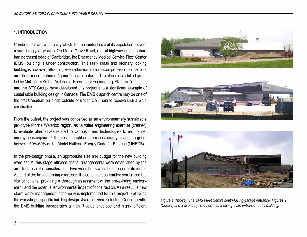
Figure 1 (Above): The EMS Fleet Centre south-facing garage entrance. Figures 2 (Centre) and 3 (Bottom): The north-east facing main entrance to the building.
1. INTRODUCTION
Cambridge is an Ontario city which, for the modest size of its population, covers a surprisingly large area. On Maple Grove Road, a rural highway on the subur-ban northeast edge of Cambridge, the Emergency Medical Service Fleet Center (EMS) building is under construction. This fairly small and ordinary looking building is however, attracting keen attention from various professions due to its ambitious incorporation of “green” design features. The efforts of a skilled group led by McCallum Sather Architects, Enermodal Engineering, Stantec Consulting and the BTY Group, have developed this project into a significant example of sustainable building design in Canada. The EMS dispatch centre may be one of the first Canadian buildings outside of British Columbia to receive LEED Gold certification.
From the outset, the project was conceived as an environmentally sustainable prototype for the Waterloo region, as “a value engineering exercise [created] to evaluate alternatives related to various green technologies to reduce net energy consumption.”2 The client sought an ambitious energy savings target of between 50%-60% of the Model National Energy Code for Building (MNECB).
In the pre-design phase, an appropriate size and budget for the new building were set. At this stage efficient spatial arrangements were established by the architects’ careful consideration. Five workshops were held to generate ideas. As part of the brainstorming exercises, the consultant committee scrutinized the site conditions, providing a thorough assessment of the pre-existing environ-ment, and the potential environmental impact of construction. As a result, a new storm water management scheme was implemented for this project. Following the workshops, specific building design strategies were selected. Consequently, the EMS building incorporates a high R-value envelope and highly efficient

2
ADVANCED STUDIES IN CANADIAN SUSTAINABLE DESIGN
3
EMS FLEET CENTRE
Figure 4 (Top): Floor Plan of the EMS Building. Figure 5 (Bottom): Building elevations. HVAC and lighting systems to reduce energy consumption, while exploiting clean renewable energy through both passive and active design features.
2. THE EMS PROGRAM
The function of this facility is to act as a 24-hour emergency medical service (ambulance) fleet centre. A minimum of six vehicles are stocked in the garage at any given time. The total crew active in the centre at any time consists of only three personnel, one supervisor, and two maintenance workers. Ambulance personnel arrive to pick up their vehicles, stock them, and are then dispatched to various “waiting stations” throughout the city. Office and administration staffs use the building only on weekdays.
The building is divided into three distinct areas: 1) administration, 2) fleet, and 3) crew. Two functional and simple rectangles connected at right angles form the layout of the building in plan; one is for administration, the other is for vehicle storage. The administration area is composed of offices, a training room, two separate change rooms and showering facilities for male and female crew members, and a lounge with a dining and kitchen area. During the design, con-struction and commissioning of the building, sustainable architectural principles were consciously incorporated at every stage. The sustainable design features used in the building do not affect its appearance however; in fact, they remain largely inconspicuous to the untrained observer. Greg Sather, the project architect, feels that there is no need to show off the building’s “green” features. According to Sather, sustainable architecture need not influence a building’s “style:” a building can be very “green” without looking “green.”3 The overall building form is very simple: a single sloped roof covers the garage

4
ADVANCED STUDIES IN CANADIAN SUSTAINABLE DESIGN
5
EMS FLEET CENTRE
Figure 6 (Above): EMS Building Site Plan. Figure 7 (Below Left): Sun Angle Sketch. Figure 8 (Below Right): View of the building overhangs while under construction.
12
3
while a double-sloped roof covers the administration area. This form allowed for east-facing clerestory windows to be incorporated into the garage area. Because of the utilitarian nature of the garage, no windows were included in the western façade, thus minimizing solar gain by blocking west sunlight. Large overhangs in the administration area provide shading to its south facing windows, and protect the wall finish from rain. The length of the overhangs is 1/3 of the wall height, calculated according to the site’s latitude and building orientation in order to block the summer sun while allowing for light penetration in the winter.
3. SUSTAINABLE SITES
3.1 Site Selection and Reduced Site Disturbance
The Emergency Medical Service Fleet Center is located off a suburban highway in Cambridge, Ontario. The site is close to a major highway (401), so vehicles can readily service a wide area. This EMS building and its external parking facility are situated on a 0.99 hectare site located partially on the Regional (Emergency) Operations site and partially on the Police headquarters’ land. Although a suburban area, it is accessible by a public bus line – although it runs infrequently. Bike racks and showers are incorporated into the building to encourage the use of alternative transportation to the site.
Existing landscaping on the site includes turf cover and about ninety trees. The site had a pre-existing operations center, laboratory, and the old EMS Central Fleet building. The stucco finish of the new EMS building was chosen to match that of the existing buildings. The new building was placed parallel to the near-est existing building in order to allow maximum sunlight for both of them. “The

4
ADVANCED STUDIES IN CANADIAN SUSTAINABLE DESIGN
5
EMS FLEET CENTRE
Figure 9 (Above Left): EMS Fleet Centre building orientation for best solar perfor-mance. Figure 10 (Above Right): Garage ceiling. Figure 11 (Below): Office ceiling.
building orientation exploits solar options which include natural day lighting of interior spaces, controlled solar gain into the building and an exterior photo voltaic array for energy conversion. Portions of the building roof and walls are oriented due south to capitalize on solar options. The existing Operations Centre has an orientation of approximately 12.5 degrees off due north so it was decided that the EMS building could be located at the same orientation of 12.5 degrees.”4
“Touch the earth lightly”- the widely accepted maxim of minimum site distur-bance for a sustainable site – was taken to heart for the new EMS building. During construction silt fencing and sediment traps were used to prevent the loss of topsoil and the sedimentation of storm sewer. Both erosion and sedi-mentation control are prerequisites for LEED – the building industry’s standard rating system of a project’s sustainability. All the healthy trees displaced by the building were relocated to open space as a conservation measure that not only saves the trees, but also stabilizes the soil and prevents erosion. The building footprint is balanced by the large open space that greatly exceeds the local zoning’s requirement, thereby also contributing to a sustainable site.
Site work was complicated, however, by the presence of soil rich with organic matter. “Organic soils that were covered with soil fill during the original develop-ment of the Operations Centre site [became] a source of methane gas. [Thus] a decision was made to leave the organics in place, and to construct [the new building] using caissons. The amount of methane produced [on site] is minimal, but does represent a potential explosion hazard.”5 As a result, the new EMS building required a methane collection system “intended to intercept the meth-ane before it enters the building and to disperse it to the outdoors.”6

6
ADVANCED STUDIES IN CANADIAN SUSTAINABLE DESIGN
7
EMS FLEET CENTRE
3.2 Storm Water Management and Treatment7
A pre-existing storm water management strategy was implemented in 1990. This strategy included an elaborate drainage plan and a large diameter storm sewer. Pre-existing storm sewers connect to a manhole on the storm line located cen-trally on the EMS site. The sewage lines are then connected to a municipal lift station located to the south-west of the site. The operation and capacity of this system was reviewed to assess whether or not it could handle output from the new facility’s operations, including the discharge of contaminated water from the ambulance wash bays. The run-off volumes for both existing and proposed surfaces were first calculated. Modeling was used to assess peak flows and volumes under pre-existing and proposed conditions, as outlined in Table 3.1.
The storm water management strategy adopted for the new building matches the quantity of runoff from the new and existing buildings to that of pre-devel-opment rates while providing adequate treatment. The measures involve the collection of roof water in a buried cistern and the directing of surface runoff to bio-swales. Careful grading of the site funnels storm run-off into an existing on-site storm water management facility. The clean run-off from the roof is collected in a buried cistern, without affecting pre-existing drainage patterns. Based on typical rainfall in the Waterloo region (approximately 76mm per month), an estimated 130m3 of water collected in the cistern is always readily available for re-use.8 Landscaped areas drain over land through surface swales, while run-off from the parking lots is also directed to existing storm sewers via vegetated swales. As a secondary measure, the pre-existing storm sewer was relocated and extended to accommodate any increased in volume.
Table 3.1: EMS Building Runoff Volume Summary (m3)
Site ExistingProposed Surfaces Total
ProposedRoof Parking Ground
25year 31 32 44 19 94
2 year 41 36 50 24 110
5 year 84 53 72 49 174
100 year 541 166 223 315 704
Source: Table 4.2b, page 11, Emergency Medical Services-Central Fleet Facility preliminary schematic design report
Figure 12 (Right): The storm water management plan works with existing systems.

6
ADVANCED STUDIES IN CANADIAN SUSTAINABLE DESIGN
7
EMS FLEET CENTRE
Figure 13 (Above): Crab apple trees were planted to amidst the existing landscaping. Figure 14 (Below Left): Silt fencing. Figure 15 (Below Right). An on-site bio-swale.
3.3 Landscaping and Exterior Design
Trees were relocated to provide shading and to create a pleasing visual setting for the building. Specific vegetation such as low growing sedges and reeds planted into the swales assist in purifying the surface water run-off. Different options were considered for exterior hard surfaces used for driveways and parking areas. Pre-cast pavers, limestone screenings, porous traffic surfaces, poured-in-place concrete and conventional asphalt paving were compared in terms of economy, duration, aesthetics and environmental effects. Despite an attraction for the first two options, both had to be rejected due to their vulnerabil-ity to damage and degradation from snow ploughing necessary in wintertime. In the end, asphalt was selected over pip concrete for reasons of economy and liability issues pointed out by the facility’s insurance company.
Among other landscaping and exterior design considerations, special attention was also paid to reducing ambient light pollution. “Dark Sky” exterior lighting fixtures with low cut-off angles were used to minimize light pollution and glare. Pedestrian lighting poles (4.6 m tall, 70 watts) were also used. Although less powerful than conventional lights, they still provide safe levels for walkways. In the parking lots 9.1m lamp poles with fixtures of up to 400-watts safely light people’s cars while reflecting little into the ambient area.
4. SUSTAINABLE DESIGN
4.1 Water Efficiency
Landscape irrigation for the EMS Building uses collected rainwater; no perma-nent irrigation system was installed. These two measures greatly reduce the

8
ADVANCED STUDIES IN CANADIAN SUSTAINABLE DESIGN
9
EMS FLEET CENTRE
building’s potable water consumption. In addition, areas disturbed by construc-tion were re-seeded with a mixture of native, drought resistant wild flowers and grasses, thus eliminating the need to install an automatic sprinkler system. This low maintenance landscaping also minimizes mowing and plant trimming expenditures.
Four methods are used to further reduce the building’s use of potable water: 1) waterless urinals, 2) dual-flush toilets, 3) front loading washing machines, and 4) the use of rain water for irrigation and flushing of toilets. Table 4.1 demonstrates how these strategies and devices significantly reduce water consumption.
4.2 Energy Performance
Theoretically, through the measures introduced into the EMS Building, an 80% savings of latent energy is achievable. However, in practice the building achieves only 50% energy savings compared to the MNECB which is still a remarkable accomplishment. The principal strategy for reducing the EMS build-ing’s energy consumption was based on “cumulative effects.” In other words by integrating different sustainable systems such as high-efficiency lighting and HVAC systems, a heat recovery system for the building’s ventilation, photo-vol-taic panels, and increased insulation in the building envelope, the overall effect was massive energy savings.
To calculate the potential energy savings of the building during the design pro-cess, EE4 computer software was used to create two simulated buildings – one a reference standard based on measures to achieve the energy performance of a building designed to meet the MNECB, and the other according to the measures used in the EMS Building. The comparison of the two buildings is
Table 4.1: EMS Building Water Consumption (m3/year)Water End Use Standard
practiceProposed design
% Savings
Landscaping domestic (indoor) supplied by cistern
2609715 -
225548(285)
91%23%
Purchased water cost of water
3324$ 4,987
488$638
85%
Source: Table 4.7b, page 31, Emergency Medical Services-Central Fleet Facility preliminary schematic design report
Figure 15 (Below): Manifold for the EMS Building’s in-floor radiant heating system.

8
ADVANCED STUDIES IN CANADIAN SUSTAINABLE DESIGN
9
EMS FLEET CENTRE
shown in Table 4.2. Insulation levels in the EMS Fleet Centre building envelope are a dramatic improvement over the MNECB and current regional practice. Computer modelling, taking thermal bridging factors into account, determined proper insulation values.
Energy savings and thermal comfort were the two principal reasons that radiant in-floor heating was used in both the office and garage areas of the building instead of typical forced-air heating. Radiant heating is also more compatible with displacement ventilation – the building’s system of air supply – since it does not upset airflow patterns. There was no need too install a DX cooling system in the locker rooms, due to use of a Drykor dehumidification system (described in section 5.4).
T5 fluorescent lamps were used throughout the building for their efficient perfor-mance and ready availability. The variety of light fixtures was also minimized to simplify bulb replacement. Area function dictated specific zoned light levels. The T5 light fixtures used in the office areas have louvered, suspended balustrades to provide a glare free light. This type of fixture can be more widely spaced while maintaining uniform lighting. The maximum MNECB lighting power density is 11.3 W/m2, however the lighting power density of the EMS is only 7.3 W/m2 – 35% below the model code values while maintaining acceptable lighting levels.
A ventilation heat recovery system also helps reduce the building’s energy con-sumption. It recycles heat from the exhaust air for preheating incoming air, thus saving energy. Two types of heat recovery systems were installed: a plate type and an enthalpy wheel. Wheel type units which can recover about 80% of the heat and 50% of the humidity from the exhaust air are used in the administration building, since the administration area is both dehumidified and air conditioned.
Table 4.2: EMS Building Energy Savings Comparison
Building Component Reference Building (MNECB)
Region Current Practice
The EMS Fleet Centre
Wall R-value R-10.4 R-15 R-30(office) R-24(garage)
Roof R-value R-24 R-24 R-28(office) R-24(Garage)
Window Type and U-value in Btu/hr ft2 ºF
Double-glazed 0.60
Double-glazed Low-e 0.40 Low-e 0.10
Heating equipment efficiency 80% 81% In-floor
Heating
Cooling equipment efficiency EER = 8.5 EER = 11.0 (DX and
Drykor)
Economizer Yes Yes Yes (?)
Heat Recovery None None Yes
Lighting Power Density 10 W/m² 7.3 W/m² 7.3 W/m²
Lighting Control None Occupancy Sensors
Occupancy and daylight Sensors
Source: Adapted from pages 7 and 34 of the Emergency Medical Services - Central Fleet Facility Preliminary Schematic Design Report

10
ADVANCED STUDIES IN CANADIAN SUSTAINABLE DESIGN
11
EMS FLEET CENTRE
A plate type system, which recovers about 70% of the heat from the exhaust air, is used in the garage, as the garage is heated only.
A displacement ventilation system was chosen for several reasons as discussed in the EMS Preliminary Design Report: “Conventional ventilation systems try to create a fully mixed air condition. Air is supplied at the ceiling level and diffusers attempt to mix the fresh air throughout the space. With displacement ventilation air is provided low in the space (either low on the wall or at the floor) and is exhausted at the ceiling. Ideally air is not re-circulated. Displacement ventilation saves energy because the garage and office ventilation systems are less likely to run at high speed to remove the contaminants.”9
The building’s energy savings also result from the building’s ability to supply part of its own energy requirements. The south-facing roof of the administration area supports a solar energy photovoltaic array. The 5kw PV system installed on this project has a scaleable configuration to facilitate any future needs for expansion. This PV system will save 14% of the building’s electrical demand. The system can readily be reconfigured for two options: grid-tied and stand-alone. After negotiations with the local utility company, special approval was granted for feedback into the local 600 V transformer supplying the entire Operations Centre site (through which it connects to the larger power grid). The site as a whole has a large base load, so any surplus electricity would thus be consumed in the Operations Centre, avoiding any net feedback into the grid per-se, while reducing the amount of grid power drawn. Thus the photovoltaic array could simultaneously be considered grid-tied and stand-alone. Although such a PV system is still expensive, the Waterloo region is eager to gain some experience by trying this technology in anticipation of broader implementation in the near future. (ATS of Cambridge is expected to develop a PV system for half the current cost, adding to the financial viability of its wide scale use).
The energy consumption target of between 50% - 60% lower than that required by the MNECB has been successfully achieved by the EMS Building through its various savings measures. The variance in savings accounts for the con-tributions (or lack thereof) of the PV array: 52% energy cost savings without, or 58% with. High insulation levels, waste energy recovery sensors, medium efficiency equipment, superior windows, lighting conservation and other “basic” design principles and systems were alone sufficient to achieve a 40% energy use reduction. The final 10% to 20% was achieved through the use of high effi-ciency equipment, radiant in-floor heating, and an alternate cooling system for the locker rooms (dehumidification).
4.3 Reduced Contribution to Atmospherci Pollution
In 1930, Thomas Midgley invented a new chemical, the chlorofluorocarbon, oth-erwise known as a CFC. A CFC molecule can destroy up to 100,000 ozone mol-ecules in the atmosphere. Fifty percent of CFCs produced are used in buildings as part of their air conditioning and refrigeration systems, in fire extinguishers, and in certain insulation materials.10 Contrary to typical practice, base building HVAC and refrigeration equipment installed in the EMS Fleet Centre do not contain CFCs, HCFCs, Halon or any other “greenhouse” gas.
4.4. Materials and Resources
In terms of materials and resources for the design and construction of the EMS building, sustainable strategies were implemented both in the selection of mate-rials and during the construction process. Twenty percent of the building is com-posed of regionally produced materials (such as sand and gravel aggregates)

10
ADVANCED STUDIES IN CANADIAN SUSTAINABLE DESIGN
11
EMS FLEET CENTRE
– fifty percent of which were harvested locally. Consideration was also given to the use of materials with recycled content and non-polluting finishes. These include carpet made from recycled pop bottles, sheet linoleum, sheet safety flooring in the change rooms, low VOC, water based paints, and a composite wheat/straw board panel for millwork.
A system of storage and collection of recyclables was implemented during the construction period, including a comprehensive management plan for diverting construction waste. Waste materials were placed into four categories: wood, steel, concrete block and “other” waste. As part of the plan, the collected waste was seen as a “resource” and was sold to various salvage companies. In order to receive the credit for the LEED rating system, extensive documentation was kept regarding the weight of the waste, the landfill location, and the contract with the salvage companies. All non-recyclable waste – only one quarter of the total produced - was diverted to a designated landfill.
5. ENVIRONMENTAL CONTROLS
Despite the importance of energy conservation, creating a healthy and comfort-able working environment was always the primary design consideration for the EMS Fleet Centre. Typically, Canadians spend 80% to 90% of their time inside buildings. “Recent studies suggest that improvements to indoor air can increase worker productivity by as much as 16%, resulting in rapid payback of capital investments.”11As a result, temperature, humidity, ventilation and day-lighting comfort were given carefully consideration in the design of the building. Passive and active systems are successfully integrated to achieve a pleasant working environment. In addition, low-emitting materials were specified to improve air quality both during construction and for after commissioning.
Figure 16 (Below): View of the recycling system implemented during construction.
12
ADVANCED STUDIES IN CANADIAN SUSTAINABLE DESIGN
13
EMS FLEET CENTRE
5.1 Thermal Comfort
Many people working in an office or in a garage experience cold feet in the wintertime even if ambient heat levels are maintained at typical comfort levels. Radiant in-floor heating as used in the EMS building provides a more comfort-able method of heating than a typical forced-air system, as well as reduces fan noise and helps keep the floor dry in the garage area. Because heating is separated from the ventilation system, operable windows allow occupants direct control of airflow and temperature modulation of their individual spaces without interfering with the overall building system.
5.2 Natural Daylighting and Views
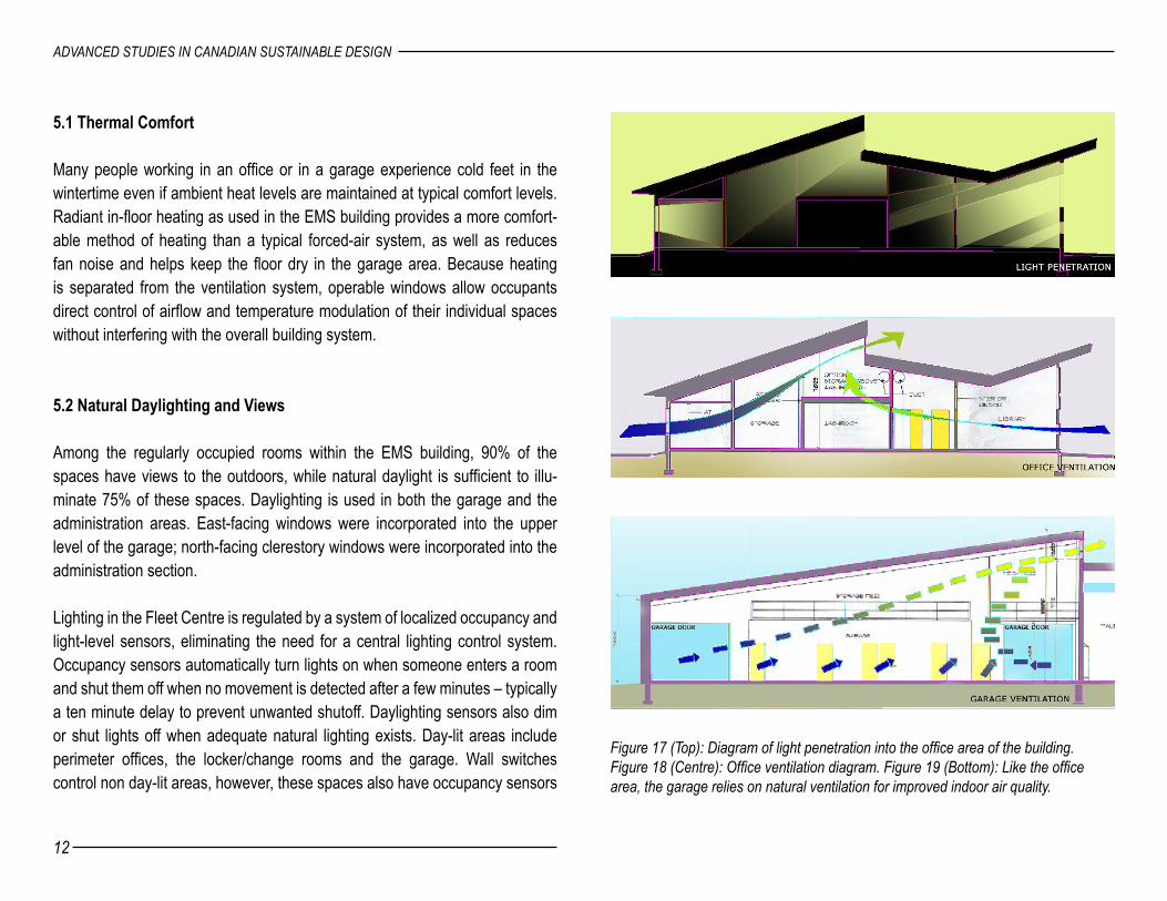
Among the regularly occupied rooms within the EMS building, 90% of the spaces have views to the outdoors, while natural daylight is sufficient to illu-minate 75% of these spaces. Daylighting is used in both the garage and the administration areas. East-facing windows were incorporated into the upper level of the garage; north-facing clerestory windows were incorporated into the administration section.
Lighting in the Fleet Centre is regulated by a system of localized occupancy and light-level sensors, eliminating the need for a central lighting control system. Occupancy sensors automatically turn lights on when someone enters a room and shut them off when no movement is detected after a few minutes – typically a ten minute delay to prevent unwanted shutoff. Daylighting sensors also dim or shut lights off when adequate natural lighting exists. Day-lit areas include perimeter offices, the locker/change rooms and the garage. Wall switches control non day-lit areas, however, these spaces also have occupancy sensors
Figure 17 (Top): Diagram of light penetration into the office area of the building. Figure 18 (Centre): Office ventilation diagram. Figure 19 (Bottom): Like the office area, the garage relies on natural ventilation for improved indoor air quality.
12
ADVANCED STUDIES IN CANADIAN SUSTAINABLE DESIGN
13
EMS FLEET CENTRE
to shut off lights when the space is not occupied. Outside lighting is controlled by photocell sensors but can also be turned off or on with the use of a built-in timing device.
5.3 Demand Controlled Ventilation
Power-operated venting louvers integrated into the windows allow for the natu-ral ventilation of all areas of the building. In the office area, an air change rate of 10 cubic feet per-minute – or 5 litres per second – per person is the accepted standard. A slower air refreshment rate could contribute to Sick Building Syn-drome (SBS). The ventilation rate for the indoor garage meets the demanding requirement of 500 CFM per vehicle. The administration section can exchange 2,225 CFM with outdoor air. The architects recognised an inherent trade-off for providing optimum air quality while also minimizing energy costs: “Ventilation air heating is the largest contributor to space heating energy consumption.”12 As a result, because air change rates are less stringent for the garage area, return air is partially diverted into the garage from the administration area as “preheated” supply air.
To maximize the efficiency of the systems, displacement ventilation is used throughout the building. The Fleet Centre also incorporates a demand-con-trolled ventilation system. The garage uses CO2 and NOx sensors to control the operation of these systems. The ventilation rate for the administration area is established according to the CO2 level in the return air. When the CO2 level is low, a room is probably unoccupied, so the outdoor air damper remains closed. When a person enters, the CO2 level rises, causing the outdoor air damper to open to provide sufficient ventilation. CO2 controls offer the benefits of energy savings when rooms are empty and better indoor air quality when occupied.
5.4 Dehumidification System
On cool days, high levels of humidity emanating from the showers in locker rooms can be vented by using the ventilation system alone. In warm, humid weather supplementary dehumidification is required. Conventional DX cooling systems can provide some humidity relief but, often over-cool in order to reduce relative humidity to acceptable levels. An alternative to standard DX cooling is a desiccant dehumidification system. A very efficient desiccant system manu-factured by Drykor dehumidifies the ventilation air for the entire administration area. It removes latent heat without generating unwanted temperature drop.
5.5 Indoor Air Quality
High indoor air quality (IAQ) performance is a critical element for maintaining the health and well being of building occupants. Comprehensive strategies to achieve these high levels were employed in the design and construction of the EMS building. Environmental tobacco smoke – otherwise known as second-hand-smoke – must is effectively controlled as per the LEED prerequisite. Waste air from washrooms and copier rooms are exhausted to the outdoors. The innovative displacement ventilation is approximately twice as effective in removing contaminants from the space as “mixed air” systems. Due to the air-tight construction of most energy efficiency architecture, the choice of construc-tion and finish materials is key to reducing the toxic chemical components in air. Thus, materials that emit low levels of volatile organic compounds (VOCs) were specified in the design. These products included water-based adhesives, paints and coatings and CRI certified carpet and composite wood products with stringent urea-formaldehyde resin limits. A two week building “flush-out” will be conducted after construction ends and prior to building occupancy.
14
ADVANCED STUDIES IN CANADIAN SUSTAINABLE DESIGN
15
EMS FLEET CENTRE
6. CONSTRUCTION
6.1 Construction Systems
Two distinct construction systems were used in the EMS Fleet Centre. A modi-fied, pre-engineered wall and roof system form the structure of the garage area, while the administration section has insulated wood stud wall framing with insu-lated pre-engineered wood trusses for the roof. A stucco exterior finish visually unifies the two sections.
6.2 Building Envelope Construction
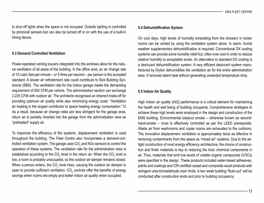
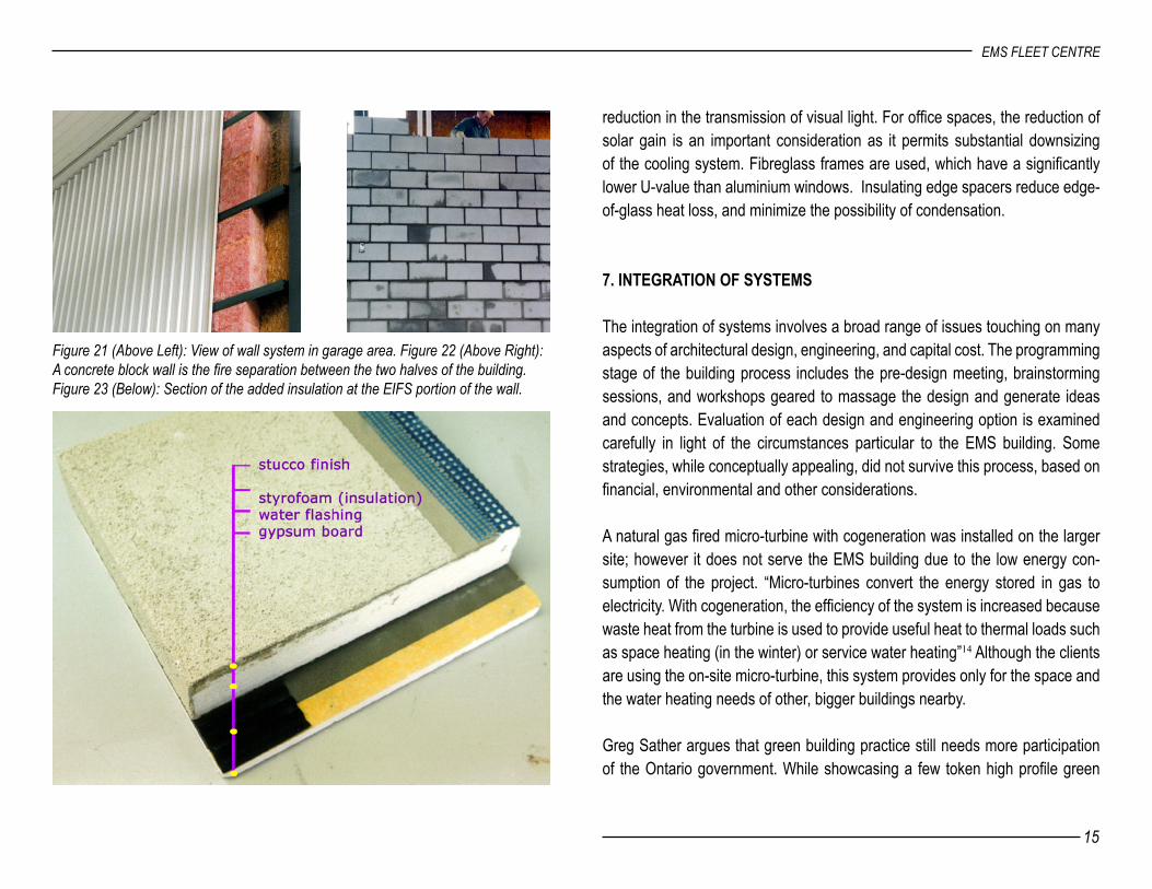
A building enclosure controls heat flow, rain penetration, wind, and moisture, acting as the most important primary buffer against the outdoor environment. The building envelope of the EMS Fleet Centre is composed of seven layers: water flashing, the exterior finish, an air barrier, insulation, the structure, a vapour barrier, and the interior finish. The vapour barrier is located on the inte-rior side of the insulation to prevent condensation within the wall cavity. In consideration of the cold Ontario winters, the insulation options for the build-ing envelope were examined with scrutiny. The proposed insulation levels of walls, roofs, windows and doors, their R-value, cost and payback period were all weighed when making the final decision. As a result, the roofs have R-31 fibreglass batting. The administration building has R-20 in the wall studs and R-10 insulation in the EIFS system. The garage walls have R-30 batt insulation in the wall cavity, plus additional insulation at EIFS locations.13 Energy efficient windows include a glazing unit with argon gas fill and low-E coating. One of the benefits of the coating chosen is a reduced solar heat gain coefficient, yet little Figure 20: Typical Wall Section through Administration area of EMS Fleet Centre.
14
ADVANCED STUDIES IN CANADIAN SUSTAINABLE DESIGN
15
EMS FLEET CENTRE
reduction in the transmission of visual light. For office spaces, the reduction of solar gain is an important consideration as it permits substantial downsizing of the cooling system. Fibreglass frames are used, which have a significantly lower U-value than aluminium windows. Insulating edge spacers reduce edge-of-glass heat loss, and minimize the possibility of condensation.
7. INTEGRATION OF SYSTEMS
The integration of systems involves a broad range of issues touching on many aspects of architectural design, engineering, and capital cost. The programming stage of the building process includes the pre-design meeting, brainstorming sessions, and workshops geared to massage the design and generate ideas and concepts. Evaluation of each design and engineering option is examined carefully in light of the circumstances particular to the EMS building. Some strategies, while conceptually appealing, did not survive this process, based on financial, environmental and other considerations.
A natural gas fired micro-turbine with cogeneration was installed on the larger site; however it does not serve the EMS building due to the low energy con-sumption of the project. “Micro-turbines convert the energy stored in gas to electricity. With cogeneration, the efficiency of the system is increased because waste heat from the turbine is used to provide useful heat to thermal loads such as space heating (in the winter) or service water heating”14 Although the clients are using the on-site micro-turbine, this system provides only for the space and the water heating needs of other, bigger buildings nearby.
Greg Sather argues that green building practice still needs more participation of the Ontario government. While showcasing a few token high profile green
Figure 21 (Above Left): View of wall system in garage area. Figure 22 (Above Right): A concrete block wall is the fire separation between the two halves of the building. Figure 23 (Below): Section of the added insulation at the EIFS portion of the wall.
16
ADVANCED STUDIES IN CANADIAN SUSTAINABLE DESIGN
17
EMS FLEET CENTRE
power projects (such as a couple of poorly sited wind mills in Toronto), the local utility company actually encourages consumption by giving a cheaper rate for massive energy consumers. Current (antiquated) provincial regulations do not permit direct feed back of surplus electricity into the grid, yet it is prohibitively costly to store on-site generated electricity in batteries.
Some other strategies that were considered during the “brainstorming” sessions were also left out of the EMS project due to other such circumstances as the micro-turbine. Although discarded in the design process, it is still worthwhile to briefly review some of these unused ideas. A couple of these ideas were so appealing to some members of the design team that they actually implemented them in their own houses. For instance, a wastewater heat recovery system pre-heats a building’s in-coming cold water supply using heat extracted from the wastewater from showers and sinks. The cold water supply is circulated through a copper pipe wound around a section of copper drainpipe. Because the EMS building has no basement, the extra installation required and the infrequency of shower taking held back applica-tion of this idea. A second such idea was solar ventilation air heating. In this system, cold air is heated by being pulled inside through a sun-exposed black metal clad cavity. This “solar-wall” preheating of the air reduces the time and energy needed to defrost the heat recovery unit in cold weather. Unfortunately, Enermodal’s system had a design similar to that of the patented “Solar Wall” – the use of which would have caused additional unanticipated licensing costs. Wind power was also rejected for this project because of the low wind levels of the site’s microclimate. Wind energy is not considered an economically viable energy option when annual average wind speed is less than 4.0m/s. The aver-age wind speed (measured at Waterloo Airport) is only 3.4m/s.
8. COSTING
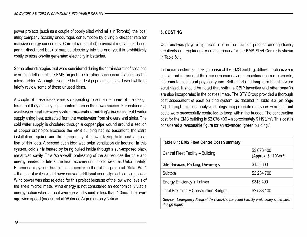
Cost analysis plays a significant role in the decision process among clients, architects and engineers. A cost summary for the EMS Fleet Centre is shown in Table 8.1.
In the early schematic design phase of the EMS building, different options were considered in terms of their performance savings, maintenance requirements, incremental costs and payback years. Both short and long term benefits were scrutinized. It should be noted that both the CBIP incentive and other benefits are also incorporated in the cost estimate. The BTY Group provided a thorough cost assessment of each building system, as detailed in Table 8.2 (on page 17). Through this cost analysis strategy, inappropriate measures were cut, and costs were successfully controlled to keep within the budget. The construction cost for the EMS building is $2,076,400 – approximately $1193/m². This cost is considered a reasonable figure for an advanced “green building.”
Table 8.1: EMS Fleet Centre Cost Summary
Central Fleet Facility – Building $2,076,400 (Approx. $ 1193/m²)
Site Services, Parking, Driveways $158,300
Subtotal $2,234,700
Energy Efficiency Initiatives $348,400
Total Preliminary Construction Budget $2,583,100
Source: Emergency Medical Services-Central Fleet Facility preliminary schematic design report

16
ADVANCED STUDIES IN CANADIAN SUSTAINABLE DESIGN
17
EMS FLEET CENTRE
Table 8.2: Cost Assessment of Proposed Building SystemsOptions Capital
Cost Annual Savings
Payback(Years)
CBIPElligible
Use(Yes/No)
Comment
Micro-turbine cogeneration 1,500/kw $264 5.7 Yes LimitedPhotovoltaics $12,000/kw $89 90 Yes Yes Expected future cost decreaseRadiant in-floor heating $74,000 $ 600 12 Yes Yes Working environmental improvementsVentilation heat recover $8,400 $3,058 3 Yes Yes Displacement ventilation $4,000 $1,605 2.5 No YesDemand-control ventilation &4,800 $1887 2.5 Yes YesDehumidification system (Drykor) $8,000 $262 20+ Yes Yes Indoor environment improvementsRainwater cistern (8 cubic m) $6,900 $428 16 Yes Significant water savingsOccupancy /daylight control $5,600 1,046 5.5 Yes Yes Avoided capital $493Efficient lighting $1,496 $2,624 -2.2 Yes Yes Avoided capital $4,432Window with fibreglass frames $15,800 $1,223 10.6 Yes Yes Avoided capital $2,808Window with low-e =0.1 15,800 $1,228 11.2 Yes Yes Avoided capital $2,093Dual-flush toilet $75 ea 9 YesBetter office wall R-30 $162 $1,400 7.1 Yes Yes Avoided capital $257Better garage wall R-24 $ 3,100 $372 8 Yes Yes Avoided capital $112Better office roof $4,100 $181 19.2 Yes Yes Avoided capital $632Better garage roof $4,875 $190 25.4 Yes Yes Avoided capital $56Solar ventilation air heating (50m2) N.A. $500 8 Yes Yes Unexpected extra costWater heat recover system $2,500 $355 7 No 20 year payback and other considerations Wind Energy $7,000 $52 130 No Long payback due to the low wind speed regionGround source heat pumps $4,000/ton 20+ No Long payback and nature gas availableSolar water heater $12,000 $191 20+ No Long payback versus natural gas Source: Emergency Medical Services-Central Fleet Facility preliminary schematic design report
18
ADVANCED STUDIES IN CANADIAN SUSTAINABLE DESIGN
19
EMS FLEET CENTRE
When asked how to design an advanced sustainable building within a reason-able budget, other than through a thorough early cost and performance evalu-ation, Greg Sather suggests a couple of strategies to be considered during the design process. After insuring that all the desired energy efficient initiatives and incentives have been exploited, the architect can use shrewd design options to manipulate and balance different costs. For example, in the EMS building, large roof overhangs preclude the need for separate shading devices over the windows.
Another method of “finding” money to spend on “green” features is by cutting unnecessary components. For instance, many naturally textured materials have a pleasing finish. If these are chosen for the interior structure and surfaces, extra painting and finishing will not be needed. Additionally, in situations where exposure of ducts and pipes is not objectionable, a ceiling system would not be necessary. The significant incremental capital and maintenance savings made through such strategies can be spent on the “green” features. Using such strat-egies, McCallum Sather Architects have designed an advanced energy efficient project while controlling the budget within a mere 1% over that of a normal building!
9. LEADERSHIP IN ENERGY AND ENVIRONMENTAL DESIGN
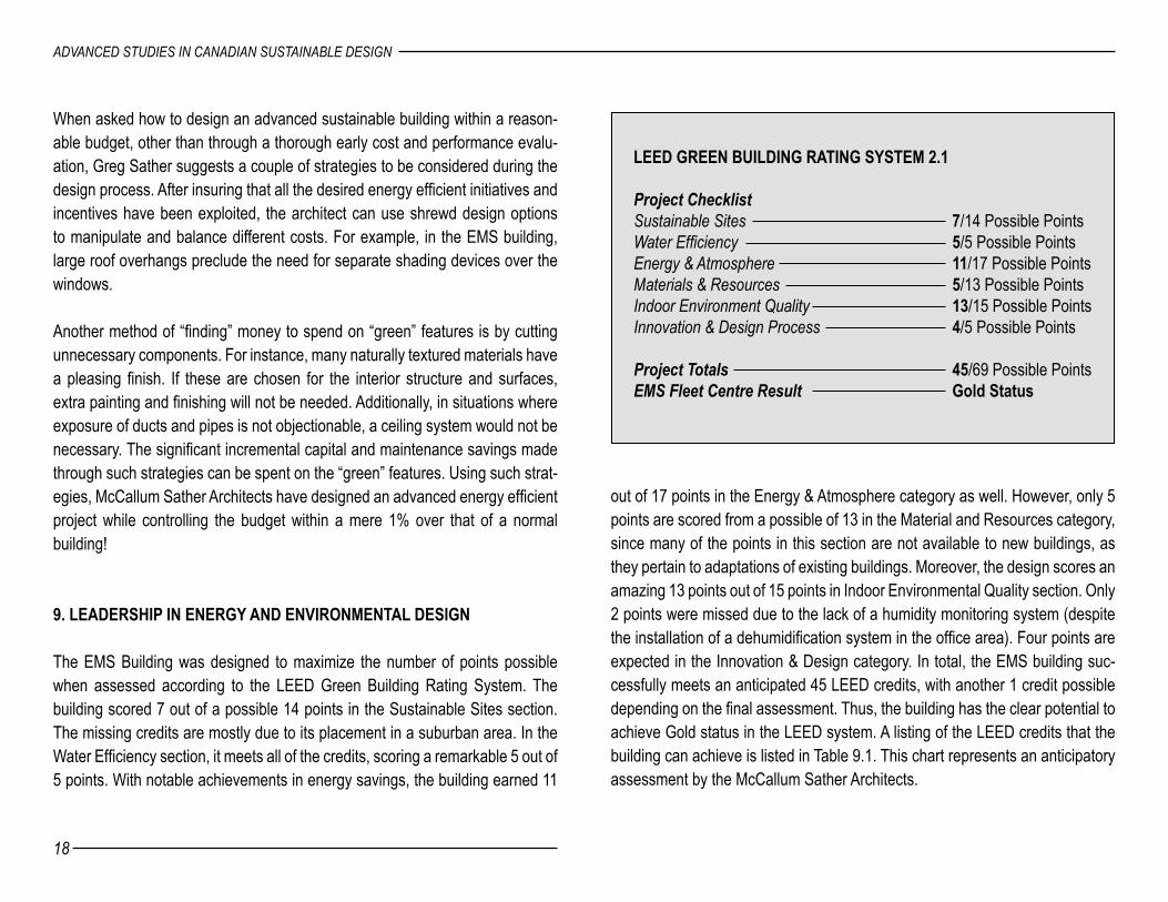
The EMS Building was designed to maximize the number of points possible when assessed according to the LEED Green Building Rating System. The building scored 7 out of a possible 14 points in the Sustainable Sites section. The missing credits are mostly due to its placement in a suburban area. In the Water Efficiency section, it meets all of the credits, scoring a remarkable 5 out of 5 points. With notable achievements in energy savings, the building earned 11
LEED GREEN BUILDING RATING SYSTEM 2.1 Project Checklist Sustainable Sites 7/14 Possible Points Water Efficiency 5/5 Possible Points Energy & Atmosphere 11/17 Possible PointsMaterials & Resources 5/13 Possible PointsIndoor Environment Quality 13/15 Possible PointsInnovation & Design Process 4/5 Possible Points Project Totals 45/69 Possible PointsEMS Fleet Centre Result Gold Status
out of 17 points in the Energy & Atmosphere category as well. However, only 5 points are scored from a possible of 13 in the Material and Resources category, since many of the points in this section are not available to new buildings, as they pertain to adaptations of existing buildings. Moreover, the design scores an amazing 13 points out of 15 points in Indoor Environmental Quality section. Only 2 points were missed due to the lack of a humidity monitoring system (despite the installation of a dehumidification system in the office area). Four points are expected in the Innovation & Design category. In total, the EMS building suc-cessfully meets an anticipated 45 LEED credits, with another 1 credit possible depending on the final assessment. Thus, the building has the clear potential to achieve Gold status in the LEED system. A listing of the LEED credits that the building can achieve is listed in Table 9.1. This chart represents an anticipatory assessment by the McCallum Sather Architects.
18
ADVANCED STUDIES IN CANADIAN SUSTAINABLE DESIGN
19
EMS FLEET CENTRE
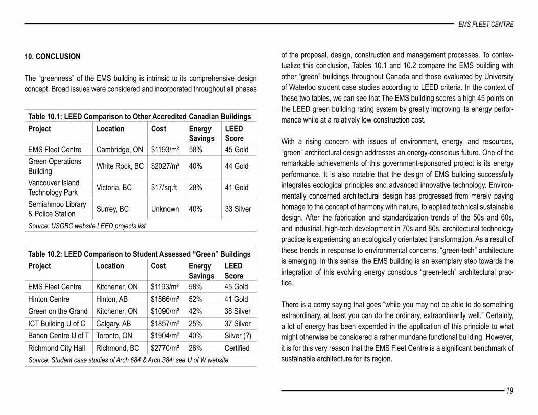
of the proposal, design, construction and management processes. To contex-tualize this conclusion, Tables 10.1 and 10.2 compare the EMS building with other “green” buildings throughout Canada and those evaluated by University of Waterloo student case studies according to LEED criteria. In the context of these two tables, we can see that The EMS building scores a high 45 points on the LEED green building rating system by greatly improving its energy perfor-mance while at a relatively low construction cost.
With a rising concern with issues of environment, energy, and resources, “green” architectural design addresses an energy-conscious future. One of the remarkable achievements of this government-sponsored project is its energy performance. It is also notable that the design of EMS building successfully integrates ecological principles and advanced innovative technology. Environ-mentally concerned architectural design has progressed from merely paying homage to the concept of harmony with nature, to applied technical sustainable design. After the fabrication and standardization trends of the 50s and 60s, and industrial, high-tech development in 70s and 80s, architectural technology practice is experiencing an ecologically orientated transformation. As a result of these trends in response to environmental concerns, “green-tech” architecture is emerging. In this sense, the EMS building is an exemplary step towards the integration of this evolving energy conscious “green-tech” architectural prac-tice.
There is a corny saying that goes “while you may not be able to do something extraordinary, at least you can do the ordinary, extraordinarily well.” Certainly, a lot of energy has been expended in the application of this principle to what might otherwise be considered a rather mundane functional building. However, it is for this very reason that the EMS Fleet Centre is a significant benchmark of sustainable architecture for its region.
Table 10.1: LEED Comparison to Other Accredited Canadian BuildingsProject Location Cost Energy
Savings LEED Score
EMS Fleet Centre Cambridge, ON $1193/m² 58% 45 GoldGreen Operations Building White Rock, BC $2027/m² 40% 44 Gold
Vancouver Island Technology Park Victoria, BC $17/sq.ft 28% 41 Gold
Semiahmoo Library & Police Station Surrey, BC Unknown 40% 33 Silver
Source: USGBC website LEED projects list
Table 10.2: LEED Comparison to Student Assessed “Green” BuildingsProject Location Cost Energy
SavingsLEEDScore
EMS Fleet Centre Kitchener, ON $1193/m² 58% 45 GoldHinton Centre Hinton, AB $1566/m² 52% 41 GoldGreen on the Grand Kitchener, ON $1090/m² 42% 38 SilverICT Building U of C Calgary, AB $1857/m² 25% 37 SilverBahen Centre U of T Toronto, ON $1904/m² 40% Silver (?)Richmond City Hall Richmond, BC $2770/m² 26% CertifiedSource: Student case studies of Arch 684 & Arch 384; see U of W website
10. CONCLUSION
The “greenness” of the EMS building is intrinsic to its comprehensive design concept. Broad issues were considered and incorporated throughout all phases

20
ADVANCED STUDIES IN CANADIAN SUSTAINABLE DESIGN
BIBLIOGRAPHY
Publications1. Harrison, Andrew, Wheeler, Paul, and Whitehead, Carolyn, Editors.
The Distributed Workplace: Sustainable Work Environment, Spon Press.
2. McCallum Sather Architects Inc. Construction Design of Emergency Medical Services Fleet Centre, Cambridge, Ont.
3. McCallum Sather Architects Inc.; Enermodal Engineering Limited; Stantec Consulting; BTY Group, Emergency Medical Services-Central Fleet Facility Preliminary Schematic Design Report
4. McCallum Sather Architects. LEED Scorecard.5. Region of Waterloo Corporate Resources Dept. Facilities
Management & Fleet Services, Project Manual for Emergency Medical Services Fleet Centre.
6. U.S. Green Building Council, LEED Green Building Rating SystemTM Version2.0
7. Vale, Brenda and Robert. Green Architecture: Design for an Energy Conscious Future. A Bulfinch Press Book Little, Brown and Company: 1991.
Personal Interviews1. Kari Feldman, EMS Fleet Centre project manager.2. Greg Sather, EMS Fleet Centre project architect.
ACKNOWLEDGEMENTS
Without the comprehensive materials supplied to me by Greg Sather the architect, Kari Feldman the project manager, and the follow up interview at the project site with both Mr. Sather and Mr. Feldman, this case study could not have been possible. They supplied images 4, 5, 6, 7, 9, 12, 17, 18, 19,
20 and 23. Without the help of Jenny, a University of Waterloo co-op student who harvested the data for the LEED Scorecard, most details about this remarkable building would have gone undocumented. To all of them, including Alex Georgiadis who kindly edited my English usage, I am indebted. Note: All other images are by the author.
ENDNOTES
1. Data from Emergency Medical Services-Central Fleet Facility Preliminary Schematic Design Report
2. Emergency Medical Services-Central Fleet Facility Preliminary Schematic Design Report, Pg. 3
3. Interview with Greg Sather at the EMS site4. Emergency Medical Services-Central Fleet Facility Preliminary
Schematic Design Report, Pg. 85. Email correspondence from Kari Feldmann of May 13, 20046. Email correspondence from Kari Feldmann of May 13, 20047. All data from Emergency Medical Services-Central Fleet Facility
Preliminary Schematic Design Report8. Data from Emergency Medical Services-Central Fleet Facility
Preliminary Schematic Design Report9. Emergency Medical Services-Central Fleet Facility Preliminary
Schematic Design Report, Pg. 2910. Brenda and Robert Vale,199111. Emergency Medical Services-Central Fleet Facility Preliminary
Schematic Design Report, Pg. 3212. Emergency Medical Services-Central Fleet Facility Preliminary
Schematic Design Report, Pg. 2713. Email correspondence from Kari Feldmann of May 13, 200414. Emergency Medical Services-Central Fleet Facility Preliminary
Schematic Design Report, Pg. 25