Embed Size (px)
Citation preview

HWO SV
SV
HWO
R
DRSL
DR
CWI
S
Key:
HW
O
: Threaded outgoing hot water.
R : Threaded heating loop return.
CWI
: threaded incoming w
ater.T
: 3 X 3/4” sleeve ( thermom
eter ,thermostat).
S : Sensor.
F : 400 m
m diam
eter inspection manhole.
SL : Support cylindrical legs.
SV : Safety valve.
DR
: Threaded discharge.
RAD
IAN
T RC 300-ECElectrical type 60 KW
( 3 Stages 3*20)M
aterial: Stainless steel 316 L.Capacity : 3000 L.W
orking pressure : 12 bar.Test pressure : 18 bar.
C A L O R I F I E R S
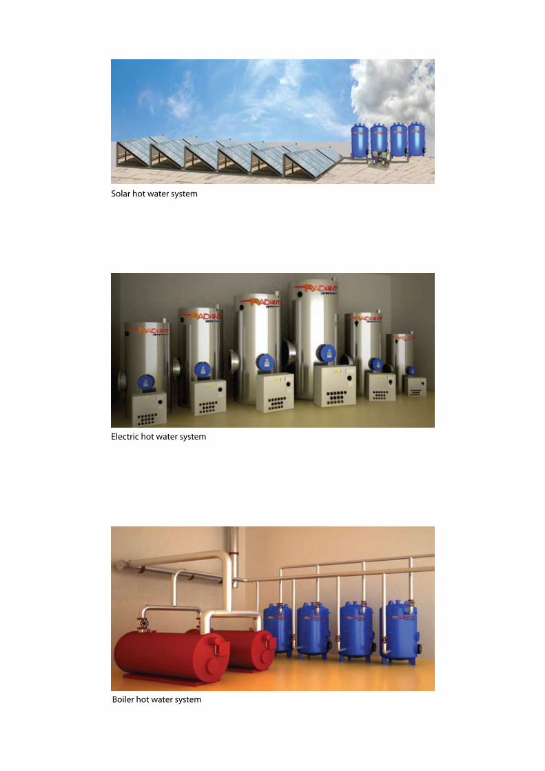
Solar hot water system
Boiler hot water system
Electric hot water system

More than 40 years of experience, con-tinuously upgraded technology, creativity, flexibility, and technical know-how, have granted RADIANT an innovative strength in manufacturing calorifiers ( Electrical cal-orifiers, Storage and Reheaters).
RADIANT is a high tech product with
wide capacities and applications.
LocationWith different manufacturing locations around Europe; Netherlands, Germany & Greece, Radiant has been designed to reach its customer without any de-lay. The various manufacturing locations contribute in offering the fastest delivery for our clients.
technoLogy & QuaLityThe latest CNC machinery, working on a CAD-CAM basis, with the vertical pro-duction integration, facilitates immediate response with best economic and quality results, enhancing the flexibility and the adaptability of the company.
RADIANT Calorifiers will closely follow
and implement all modern business and
advanced technologies, to the benefit
of its clients, delivering a product of the
highest quality. With modern state-of-the-
art machinery equipment, high expertise
in sheet metal processing, spacious and
comfortable industrial buildings,RADIANT
produces/ constructs any kind of calori-
fier, at premium quality, always according
to customers specifications.
ServiceOur close co-operation with our custom-ers, and our highly qualified personnel, ensure Radiant achieves specialization, top product quality, competitive prices, and an excellent service, meeting cus-tomers’ instructions, drawings and spec-ifications.
energy SavingCurrently, most of the heating systems in use or on offer by certain providers are designed to rely on the technology of the last century and are based on the consumption of fossil fuel such as diesel,
petroleum etc... However, Radiant calori-fiers can assure the minimum consump-tion due to the high quality of insulation and the proper engineering design for the calorifier shell.
anti LegioneLLa programAnti Legionella program is one of the con-cerns in hot water generation system:The Legionnaire’s disease is known as legionellosis. The bacteria responsible for this disease is the Legionella pneu-mophilla.This bacteria is responsible for two major diseases which are the Pontiac fever and the much more serious Legionnaires.
RADIANT systems ensure that no bac-teria will be growing in our storage tanks, as Radiant systems will keep water tem-perature maintained at above 60 C in winter and above 80 C, in summer.
C A L O R I F I E R S
go raDiant
1
Fig.1
Production
Our growing markets and the persistent demand for quality led to continuous investment in our factories lines resulting in an
automatic production of our products. However, automation does not hinder our flexibility, as our production lines are equipped
with systems that allow us to adapt products to our customer needs. Thus, not only did we achieve speed, precision and high
quality of the final product, but also adaptability to specific requirements. We managed, always in combination with the continuous
training of our staff, to achieve punctuality in delivery and high manufacturing quality.
Raw Materials
In order to be conformed to the ISO standards and provide consistency to our customers, the choice of raw materials, for all our
products, is always carried out based on quality, resistance and reliability. The continuous and intensive controls in the production
process ensure the safety and the quality of the final product.
Certificates
QUALITY. SAFETY. SERVICE. IMMEDIATE RESPONSE. CONSISTENCY
Our product is ISO certified with a CE technical file. Additionally, our company’s policy of constant
improvement of production procedures to a constant compel as improvement of our manufactured
products and enhancement of services. Our philosophy is to materialise our clients’ production needs
with the best possible, immediate, safe and qualitative way.
TECHNICAL FEATURES
Welding
A basic process in the manufacturing process makes use of the most updated methods. On the other hand, our company
uses the latest CNC machinery to perform the highest quality controls. Enamel offers excellent anticorrosive protection, has high
resistance to thermal shock, does not allow the development of bacteria and is friendly to the environment.
Coating
Enamel coating offers excellent anticorrosive protection, has high resistance to thermal shock, does not allow the development
of bacteria and is friendly to the environment. Enamel coating used is of high quality, heated at temperatures higher than 850° C
and conforms to all standards of DIN 4753 Teil 3&6 standards.
Insulation
It is one of the most basic factors for the good performance of a calorifier, the material used and its processing play a determina-
tive role for its efficiency. Two-material polyurethane is used (50 mm, 100mm thick with density 40 kg/m3).
Transportation
Transportation and storage of boilers and Calorifiers is carried out by specially designed metal pallets, achieving not only fast
transportation and storage, but also a safe one.
RADIANT Calorifier BROCHURE_V1.indd 4-5 6/8/09 12:31:30 AM
RADIANT Calorifier BROCHURE_V1.indd 1 6/8/09 12:31:24 AMRADIANT Calorifier BROCHURE_V1.indd 1 6/8/09 12:31:24 AM

Our growing markets and the persistent demand for quality
have pushed us to continuously invest in our factories lines
resulting in an automatic production of our products.
However, automation does not hinder our flexibility, as our
production lines are equipped with systems that allow us to
adapt products to our customers needs.
Thus, not only did we achieve speed, precision and high
quality of the final product, but also adaptability to specific
requirements.
We also managed due to continuous training of our staff,
to achieve punctuality in delivery and high manufacturing
quality.
In order to conform to the ISO standards and provide con-
sistency to our customers, the choice of raw materials, for
all our products, is always carried out based on quality,
resistance and reliability.
The continuous and intensive control in the production pro-
cess aims at ensuring safety and high quality.
Welding is a basic process in our manufacturing line. It
makes use of the most updated methods, using the latest
CNC machinery to perform the highest quality controls.
Radiant systems use enamel as coating to protect their
tanks. Enamel coating offers excellent anticorrosive protec-
tion, has high resistance to thermal shock, does not allow
the development of bacteria and is friendly to the environ-
ment.
The enamel coating used is of high quality, It is heated
at temperatures higher than 850° C and is conform to all
standards of DIN 4753.
CertifiCates:QUALITY – SAFETY – SERVICE – IMMEDIATE RESPONSE – CONSISTENCY
Our product is ISO certified with a CE technical file.
Additionally, our company’s policy of constant improvement of production procedures lead us to a con-
stant improvement of our manufactured products and enhancement of services. Our philosophy is to
materialise our clients’ production needs with the best possible, immediate, safe and qualitative way
proDuction
RADIANT domestic Calorifier series boasts three main different models:
1. eLectric caLorifier:An electrical control panel controlling immersion heating ele-ments mounted in the tank is used to heat water.
raw materiaLS
weLDing
coating
eXternaL caSing
A 304 BA stainless antimagnetic sheet metal may be pro-posed for external casing, fig. 3. This material is recommend-ed for areas with extensive environmental pollution, such as large cities and areas with extreme differences and alterna-tions of temperatures, such as islands. Another material is the painted galvanized sheet metal. A special electrostatic powder (polyester) is used for the painting of this type. This type of casing offers high protection for the calorifiers in areas of high solar radiation, particularly saline environment and extreme environmental conditions, such as coasts.Another material we use is painted or anodized aluminum. This material, as the previous ones, has high resistance to the extreme changes of temperatures in large urban centers burdened by pollution and coasts burdened by the saline at-mosphere. Transportation and storage of boilers and Calorifiers is carried out by specially designed metal pallets, thus achieving not only fast transportation and storage, but also safety.
inSuLation:Insulation is one of the most important processes for the good
performance of a calorifier, The material used and its process-
ing play an important role in the efficiency of the calorifier.
Normal insulation is polyurethane 100mm thickness with den-
sity of 40 kg/m3, fig. 2.
2
raDiant caLorifier typeS2. Storage caLorifier: To be combined with a domestic hot water heating system or external heat exchanger.
3. reheater caLorifier: Two types of reheaters; serpentine coil, and U-tube battery.
Fig.2 Fig.3

Electrical calorifiers are considered the most common means to generate hot water in do-mestic and industrial applications. Compared to other equipments, Electric Calorifiers are considered clean and efficient. Electrical Calo-rifiers are found in hospitals, hotels and resorts as well as residential utilities. The adaptability of these calorifiers makes them easier for the user to install and commission in some difficult situations.Size and volume of calorifiers are calculated to meet the maximum demand period (peak peri-od).The normal recovery periods vary between half-an-hour up to five hours. The advantages present in that type of Calori-fiers is as follows;1- All the power supplied to the Calorifier is transfered into heat energy. There is no heat loss such as in other equipments. 2- The space requirement is minimized. There are no attached equipments such as boilers and fuel tanks, see fig. 4
immerSion heaterSThe number of immersion heaters mounted on the flange depends on the space, the choice of stage heating and flexibility of maintenance. Small heaters normally screw into the shell.Above 15kw the tube plate is usually flanged and bolted to a neck ring. The majority of electric design calls for 3-phase, 380 - 415 volt, 50 / 60 Hz supply but any voltage can be accommo-dated. Details are required at the enquiry stage to size the heaters correctly.Immersion heaters capacity can reach up to 30 KW per stage.Radiant always recommend installing multi small screw immersion heaters up to 10 KW.Normal warranty on immersion heaters is one year against any factory defect.
Screw pLug immerSion heaterRadiant systems always recommend installing small sizes of heating elements with multi stages to guarantee the maximum efficiency and to minimize the maintenance cost in future. Usually, these are welded or brazed to a flange, with the screw plug immersion heaters are currently used for small or medium power ratings, fig. 5 These immersion heaters come in direct contact with the water. The load density can be minimized by simplyreducing the power of the electric element .
fLangeD immerSion heaterThe wide dimensional range of standard flanges allows designing flanged immersion heaters from a few hundred Watts to several hundreds of Kilowatts.The load density in this case will be high compared to the screw immersion heater, fig. 6
immerSion heater with ceramic core eLementThese immersion heaters consist of a ceramic core heat-ing element incorporated in a cylindrical sheath made of materials adapted to the heated liquid, fig. 7This type of heating elements offers many advantages: • A wide choice of materials for the sheath: steel, stainless
steel, titanium,etc.• A low watt density.• The possibility of replacing the heater without having to
empty the tank.
1- eLectricaL caLorifierS
3
Fig.4
Fig.5 Fig.6 Fig.7

inner SheLL materiaL
3- reheaterS type In many cases, tubular tubes, coils or heat exchangers are available to convert heat energy of an external source.Usually, single tubular heating coil is supplied in tanks with hot water either from steam / central heating system or from other energy source such as heat pump or solar system. The two tubular heating coils are supplied in tanks with two heating systems, one is essential, and the other heating coil or tube from subsidiary.
heating coilHeating coil is generally produced from a single tube formed into a helical coil and can operate at a greater pressure than other tube exchangers, fig. 9The cylinder size increases the length of heating coil becom-ing disproportionately greater, this heater is therefore only practical for medium size cylinders.The single coil is particularly useful for small flow rates with alarge temperature drop, fig. 10
u-tube BatteryThis type of heat exchanger is used in calorifier manufactur-ing. It uses high efficiency tubes which are not affected by thermal expansion providing extreme reliability. A wide range of multi-pass exchangers are available to ensure high heat transfer capacity.Standard bundle arrangements are manufactured from 16 mm tube although other diameters are used depending upon the duty requirement. The U-tube battery is particularly useful for big flow rates with a small temperature drop, see fig. 11
2- Storage caLorifierS
gaLvanizeD SteeL SheLLSGalvanized inner shells have proved good protection for hot water storage cylinders over many years. But it is imperative to check the quality of water and get approvals from water supply authority in your region.To extend the life of the zinc coating and allow further time for the scale deposit to form cylinders are supplied with magne-sium anodes.This disposable element is mounted inside the shell to be sac-
rificed by electrolytic action in preference to the galvanized surface. Once a satisfactory scale has formed the electrolytic action ceases, this can be checked by the continued presence of the wasted magnesium anode.Standard: Working Pressure: 10 bar Test pressure : 16 bar Operating temperature: 95°C
warningGalvanised cylinders are not suitable for use with soft water.
Galvanised steel cylinders rely upon hard salts in the water to form a protective scale. Water supplies which have tradi-tionally been hard and satisfactory softened may now prove unsuitable due to changes in source.
When a calorifier lacks an electrical heating element, it is called storage calorifier (Buffer), fig.8
Most often, storage calorifiers are attached to external
heat exchangers in order to obtain the required heat
from other parties such as fuel boiler, heat pump or solar
energy system.The storage calorifier sometimes is attached with another calorifier ( electrical, or reheater). The main purpose of such a calorifier is to store and maintain the hot water inside the tank for further utilities.
Fig.8
Fig.9
Fig.11
Fig.10
4

controL paneLS
gLaSS LineD SteeL SheLLSteel sheet E 37 with high quality glass enameled proved to be economic and reliable for the construction of the Calori-fiers shells. Glass-enameled coating has high resistance to thermal shock, prevent the development of bacteria and is environmentaly friendly. Glass enameled used is high quality, heated at temperature higher than 850 deg C and conform to all standards of DIN 4753. The correct procedure is to fit an anode in the base of the cylinder giving permanent protection to the tank.
Standard: Working Pressure: 10 bar. Test pressure :16 bar Operating temperature: 95°CExceptional: Thickness of shell and features can be adapted to meet your pressure requirements, as Radiant systems can offer higher working pressures; 12, 16 and 20 bar.
StainLeSS SteeL (316L, 316ti) Stainless steel material offers lightweight, durable design solutions to the hot water industry. Using stainless steel has demonstrated economic benefits in industries of drink-ing water treatment, storage, distribution, and waste water
The Control panels are of a minimum of 1.5mm sheet steel,
normally to IP 55 /65, mounted on the tank, connected to
the heating elements and regulations organs, composed of:
General switch contactors for immersion heaters protected
by resistor fuses, terminals for distant control, switch auto/0/
manual”, energized indicator, heating indicator, digital regula-
tion multi stages.
All electrical systems conform to European directive appli-
cable standards and carry the CE mark.
controL paneL operationSWith the test/off/auto switch in the off position turn on the
main isolator, the power ON indicator, the high temperature
fault, low flow (optional) and the low water fault (optional)
lamps will illuminate.
The Calorifier cannot be put into service until the fault reset
push button is momentarily depressed, if the Calorifier is clear
of faults the fault lamps will disappear.
• test position: Switch the test/off/auto switch to the test posi-
tion and push the test buttons, either individually, if there are
several, or push and keep depressed in the case of one but-
ton, until all the stage indication lamps have been on.
• automatic position: Switch the test/off/auto switch to the
automatic position, the automatic lamp will illuminate and the
heater comes on, this will remain the case until the desired
temperature is achieved when the heater will switch off. The
control panel will now maintain the temperature at the required
preset value.
• Shutting down: Switch off the Calorifier panel using the on/
off/auto switch and isolate the panel from the mains.
treatment installations. The metal characteristics enable stainless steels to contribute to environmental benefits through lack of contamination of drinking water, reduced environmental impact of the water industry and recyclability.Stainless Steel 316 L and/or 316 TI is used in the industries requiring high quality of hot water systems of high quality such as Hotels, Hospitals, and Schools … Etc.Stainless Steel 316 is also one of the most important ma-terials used in different application like Heat Exchangers, Food preparation equipment particularly in chloride envi-ronments, Water Filtration, Laboratory Clinical equipment.In fact, Stainless steel 316 is efficient in chloride envi-ronments.Stainless steel 316 is molybdenum-bearing grade. The molybdenum gives 316 better overall corrosion resis-tant properties, particularly Grade 316L, the low carbon version who is immune from sensitization that means no chromium material can be released in the water.Standard: Working Pressure: 10 bar. Test pressure : 16 bar Operating temperature: 95°C Exceptional: Thickness of shell and features can be adapted to meet your pressure requirements,as Radiant can offer higher working pressures; 12, 16 and 20 bar.
Fig.12
5

high Limit cut outAn independent high limit cut out device must be fitted to all direct
electrically heated calorifiers.
All other systems require an independent high limit thermostat di-
rectly connected to the control device or to an independent shut
off device.
RADIANT systems recommend the fitting of a low water cut out
device on all electrically heated calorifiers. This will prevent the risk of
switching the immersion heater ON when the calorifier is empty.
thermometer It is located near the top of the calorifier to measure the temperature
of the water reaching the outlet.
The control thermostat is normally lower down to activate the heat-
er before all the hot water has been drawn off.
A thermometer fitted to a non-storage calorifier can only act as a
guide to the heater performance. It may also be difficult to insert a
thermometer pocket in the shell.
Safety valveAll calorifiers should be fitted with a safety valve to protect the calori-
fier against over-pressure due to malfunction of controls or incorrect
operation.
Both pressure/temperature relief valves are fitted on closed instal-
lations.
manholeThe shell internals and heaters can be inspected by withdrawing the
heater. The manhole can be incorporated so that inspection does
not disturb the heater or its connections.
Most of manholes take the form of a flanged neck piece- extended
away from the shell body designated.
anodesSacrificial anodes can be supplied to counteract certain adverse
water properties.
Magnesium anodes help to protect cylinders whilst the initial deposit
of scale is formed on the shell. The combination of copper pipework
and galvanised cylinders should be avoided. The life duration of the
magnesium anodes depends on the quality of the water. Continu-
ous checks should be made to establish a service period.
insulationA proper thermal insulation is essential to prevent unnecessary heat
losses from calorifiers which may be functioning for many hours at
working temperature.
RADIANT standard factory-fitted insulation consists of 100mm thick
polyurethane foam, density 40 kg/m3, closely fitted to the shell and
encased in Stainless steel casing
control thermostatThe precision of temperature control depends on the choice of ther-
mostat and the stages arrangement for the heaters.
There may be a series of temperature switches located at different
levels in the cylinder or set at different temperatures to operate vari-
ous stages of heating.
Alternatively a single temperature switch may actuate a relay circuit
containing a timer or cam mechanism with progressive step control.
In its simplest form each stage is brought in sequentially and when
the desired temperature is reached the stages are all switched off
simultaneously.
With modulating control the temperature is monitored after each
step and the system held at the optimum number of stages.
When the thermostat is ‘integral’ with the heater it is mounted on the
tubeplate under the terminals cover. A ‘remote’ thermostat has its
own pocket and cover.
flow SwitchIt is recommended that an electric link is made between the immer-
sion heater controls and the circulating pump. This is to prevent the
heater being switched on before the pump is initiated. Additional
protection is gained by fitting a flow switch to cut out the heater if
the pump fails in service.
acceSSorieS
Drain Valve Safety Valve
Pressure Gauge Temperature Gauge
Temperature & PressureGauge
Thermometer
6

HWO T
F
R
CWI
DR SL
moDeLSCalorifiers types are mainly Horizontal and Vertical types as drawn
below in fig.13, the type configuration is based on the installation
and site circumstances.
1- Electrical calorifiers:
• Electrical calorifiers, which fully depend on electricity power to generate hot water. The calorifier is attached to three main flanges, with each flange capable of containing ten electric heating elements.
• Electric calorifier, combined with heating elements- heating coils-( sizes up to 2000 L) as back up system or alterna-tive resourse in case of electric malfunction or maintenance operation.
• Electric calorifier, combined with heating element- U Tube battery-( sizes more than 2000 L) as back up system or alternative resourse in case of electric malfunction or main-tenance operation.
Key:
HWO : Threaded outgoing hot water.R : Threaded heating loop return.CWI : threaded incoming water.T : 3 X 3/4” sleeve ( thermometer ,thermostat).F : 400 mm diameter inspection manhole.SL : Support cylindrical legs.DR : Threaded discharge.
A
C
G
L
HHWO
T
T
R
CWI
DR
SL
TR
2- Storage calorifier :Buffer tank without any heating resource ( electric, reheater) fully dependent on seperate heating resources.
3- Reheater calorifiers:• Calorifier combined with heating element- heating coil-( siz-
es up to 2000L), Electric heating elements can be provided as back up system.
• Calorifiers combined with heating element- U tube battery- ( sizes more than 2000L), electric heating elements can be provided as back up system.
• Calorifiers combined with inox heating Coil, specialized for domestic heating water ( suitable for all calorifiers sizes).
Inox heating coil Double heating coil Inox coil + U tube battery
Fig.13
Fig.14
Examples for Different models of Reheater types:
7

HWO : Threaded outgoing hot waterR : Threaded heating loop returnCWI : threaded incoming waterT : 3 X 3/4” sleeve ( thermometer ,thermostat).F : 400 mm diameter inspection manholeSL : Support cylindrical legsDR : Threaded discharge.DE : External diameter= D +10cm( insulation thickness)A : AnodeEE : Electric heating elementS : Sensor
Table 1. Capacity Ranges 150 L – 1500 L
volume (liters)* 150 200 250 300 400 500 750 1000 1500
Code (Electrical) RC15-EC RC20-EC RC25-EC RC30-EC RC40-EC RC50-EC RC75-EC RC100-EC RC150-EC
Code ( Reheater) RC15-SC RC20-SC RC25-SC RC30-SC RC40-SC RC50-SC RC75-SC RC100-SC RC150-SC
Standard Capacity( kw)electrical or heating coil** 2 3 4 4 6 8 10 15 24
Coil input/output 1” 1” 1” 1” 1” 1” 1” 1” 1 1/2”
Recirculation ¾” / ½” ¾” / ½” ¾” / ½” ¾” / ½” 1” 1” 1” 1” 1 1/2”
Cold water input 1” 1” 1” 1” 1 1/4” 1 1/4” 1 1/2” 1 ½” 1 1/2”
Hot water outlet 1” 1” 1” 1” 1 1/4” 1 1/4” 1 /2” 1 ½” 1 1/2”
Tap-anode ¾” ¾” ¾” ¾” ¾” ¾” ¾” ¾” ¾”
A 202 202 230 230 270 270 300 330 330
B 722 792 770 855 850 1068 970 1080 1260
C 800 812 870 894 952 1092 1092 1150 1290
D 555 555 600 650 750 750 950 1050 1050
E 868 1138 1250 1170 1204 1453 1630 1710 1870
H 1070 1340 1480 1410 1460 1710 1990 2030 2200
Standard Operationpressure*** 10 10 10 10 10 10 10 10 10
Standard Testing Pressure*** 15 15 15 15 15 15 15 15 15
Weight (kg)**** 78 88 119 127 145 165 190 230 340
* The dimensions above are for general information only, and they are subjected to any modification at Radiant Discretion. Exact data will be given for each order.** Standard capacity is based on 3 hours recovery. Capacity can be changed based on the actual recovery required.*** Working/ testing pressure can be modified upon request. Max working/ test pressure can be 20 bar/ 30 bar. Contact your Area Radiant Representative for special requests.**** Weights are based on standard pressure . Contact your Area Radiant Representative for special requests.
Domestic type(150L- 1500L)• Calorifiers with Electrical heating elements.• Calorifiers with Single heating coil.• Calorifiers with Single heating coil + electric back up.
sv sv sv
CWI
Fig.15 . Calorifier with electri-cal heating elements
Fig.16. Calorifier with single heating coil Fig.17. Calorifier with single heating coil-removable + electric backup
8

HWO : Threaded outgoing hot waterR : Threaded heating loop returnCWI : threaded incoming waterT : 3 X 3/4” sleeve ( thermometer ,thermostat).F : 400 mm diameter inspection manholeSL : Support cylindrical legsDR : Threaded discharge.DE : External diameter= D +10cm( insulation thickness)A : AnodeEE : Electric heating elementS : Sensor
* The dimensions above are for general information only, and they are subjected to any modification at Radiant Discretion. Exact data will be given for each order.** Standard capacity is based on 3 hours recovery. Capacity can be changed based on the actual recovery required.*** Working/ testing pressure can be modified upon request. Max working/ test pressure can be 20 bar/ 30 bar. Contact your Area Radiant Representative for special requests.**** Weights are based on standard pressure . Contact your Area Radiant Representative for special requests.
Table 2. Capacity Ranges 150 L–1500L
HWO
EE
S2
R
OUT
IN
IN
OUT
S1
HWI
DR
sv
volume (liters)* 150 200 250 300 400 500 750 1000 1500
Code RC15-DC RC20-DC RC25-DC RC30-DC RC40-DC RC50-DC RC75-DC RC100-DC RC150-DC
Coil input/output 1” 1” 1” 1” 1” 1” 10 15 24
Standard Capacity( kw)electrical or heating coil**
2 3 4 4 6 8 1” 1” 1 1/2”
Recirculation ¾” / ½” ¾” / ½” ¾” / ½” ¾” / ½” 1” 1” 1” 1” 1”
Cold water input 1” 1” 1” 1” 1 1/4” 1 1/4” 1 1/2” 1 1/2” 1 1/2”
Hot water outlet 1” 1” 1” 1” 1 1/4” 1 1/4” 1 1/2” 1 1/2” 1 1/2”
Tap-anode ¾” ¾” ¾” ¾” ¾” ¾” ¾” ¾” ¾”
A 202 202 230 230 270 270 300 330 330
B 592 692 720 805 850 960 970 1080 1160
C 674 812 870 894 952 1062 1150 1150 1200
D 555 555 600 650 750 750 950 1050 1050
E 874 1112 1170 1170 1210 1350 1630 1710 1780
H 1070 1340 1480 1410 1460 1710 1990 2030 2200
Standard Operatingpressure***
10 10 10 10 10 10 10 10 10
Standard Testing Pressure*** 15 15 15 15 15 15 15 15 15
Weight kg**** 78 93 124 156 188 212 190 230 340
sv
CWI
Fig.19. Calorifier with double heating coil- removable + electric backup
Fig.18. Calorifier with double heating coil
Domestic type (150 L- 1500L):• Calorifiers with double heating coil.• Calorifiers with double heating coil + electric back up.
9

Table 3. Capacity Ranges 2000L – 10000 L
volume (liters)* 2000 3000 4000 5000 6000 7000 8000 9000 10000
Code -(Electrical) RC200-EC RC300-EC RC400-EC RC500-EC RC600-EC RC700-EC RC800-EC RC900-EC RC1000-EC
Code- (Reheater) RC200-SC RC300-SC RC400-SC RC500-SC RC600-SC RC700-SC RC800-SC RC900-SC RC1000-SC
Standard capacity (kw)electrical and/or heating bat-tery tube/ coil
30 40 60 70 90 100 110 120 130
A 330 480 405 510 480 555 510 570 630
B 1100 1600 1350 1700 1600 1850 1700 1900 2200
D 1200 1200 1500 1500 1700 1700 1900 1900 1900
E 1870 2720 2300 2890 2720 3145 2890 3230 3570
H 2200 3200 2700 3400 3200 3700 3400 3800 4200
Standard working pressure(bar)***
10 10 10 10 10 10 10 10 10
Standard testing pressure (bar)***
15 15 15 15 15 15 15 15 15
Weight (kg)**** 410 540 710 950 1100 1300 1460 1540 1760
OUT
IN
DR
sv svsv
18cm
CWI
Fig.20. Calorifier with electrical heating elements Fig.21. Calorifier with single U-tube battery Fig.22. Calorifier with single U-tube battery + electric backup
Commercial type(2000L- 10000L)• Calorifiers with Electrical heating elements.• Calorifiers with Single U-tube battery• Calorifiers with Single U-tube battery + electric back up.
HWO : Threaded outgoing hot waterR : Threaded heating loop returnCWI : threaded incoming waterT : 3 X 3/4” sleeve ( thermometer ,thermostat).F : 400 mm diameter inspection manholeSL : Support cylindrical legsDR : Threaded discharge.DE : External diameter= D +10cm( insulation thickness)A : AnodeEE : Electric heating elementS : Sensor
10
* The dimensions above are for general information only, and they are subjected to any modification at Radiant Discretion. Exact data will be given for each order.** Standard capacity is based on 3 hours recovery. Capacity can be changed based on the actual recovery required.*** Working/ testing pressure can be modified upon request. Max working/ test pressure can be 20 bar/ 30 bar. Contact your Area Radiant Representative for special requests.**** Weights are based on standard pressure . Contact your Area Radiant Representative for special requests.

Table 4. Capacity Ranges 2000 L–10000L
volume (liters)* 2000 3000 4000 5000 6000 7000 8000 9000 10000
Code - storage RC200-DC RC300-DC RC400-DC RC500-DC RC600-DC RC700-DC RC800-DC RC900-DC RC1000-DC
Standard capacity (kw)electrical and/or heating battery tube/ coil UPON REQUEST/ SPECIAL ORDER
A 330 480 405 510 480 555 510 570 630
B 1100 1600 1350 1700 1600 1850 1700 1900 2200
D 1200 1200 1500 1500 1700 1700 1900 1900 1900
E 1870 2720 2300 2890 2720 3145 2890 3230 3570
H 2200 3200 2700 3400 3200 3700 3400 3800 4200
Standard working pressure(bar)***
10 10 10 10 10 10 10 10 10
Standard testing pressure (bar)*** 15 15 15 15 15 15 15 15 15
Weight (kg)**** 410 540 710 950 1100 1300 1460 1540 1760
svsv
18cm
CWI
Fig.23. Calorifier with double U-tube battery Fig.24. Calorifier with double U-tube battery+electric backup
Commercial type(2000L- 10000L)• Calorifiers with Electrical heating elements.• Calorifiers with Single U-tube battery• Calorifiers with Single U-tube battery + electric back up.
HWO : Threaded outgoing hot waterR : Threaded heating loop returnCWI : threaded incoming waterT : 3 X 3/4” sleeve ( thermometer ,thermostat).F : 400 mm diameter inspection manholeSL : Support cylindrical legsDR : Threaded discharge.DE : External diameter= D +10cm( insulation thickness)A : AnodeEE : Electric heating elementS : Sensor
Commercial type (1000 L- 10000L):• Calorifiers with double U-tube battery• Calorifiers with double U-tube battery + electric back up.
11
* The dimensions above are for general information only, and they are subjected to any modification at Radiant Discretion. Exact data will be given for each order.** Standard capacity is based on 3 hours recovery. Capacity can be changed based on the actual recovery required.*** Working/ testing pressure can be modified upon request. Max working/ test pressure can be 20 bar/ 30 bar. Contact your Area Radiant Representative for special requests.**** Weights are based on standard pressure . Contact your Area Radiant Representative for special requests.

The consumption of domestic hot water in public buildings
fluctuates throughout the day and where possible data should
be collected to establish the peak demand. The table below
gives typical maximum hourly demand rates for water at
60°C.
The provision of a one hour storage capacity with a one hour
heatup period is generally sufficient to cope with the peak de-
mand. If the power supply is limited it is advisable to increase
the storage volume in order to reduce the power input, as
shown in the table below.
Storage volumes if less than one hour capacity need careful
consideration. If there is a high demand for a short period the
storage volume must be sufficient to meet that demand.
Off peak heating at reduced tariff offers considerable financial
savings, particularly if the storage volume can be increased.
Unless the extra volume is sufficient to meet the entire day’s
demand subsidiary heaters are necessary to keep the top of
the cylinder hot once the overnight storage has been con-
sumed.
Storage Calorifier
As mentioned above, storage calorifiers are used for main-
taining the hot water, especially when the consumption of do-
mestic hot water in public buildings fluctuates throughout the
day and where possible data should be collected to establish
the peak demand.
There are two main ways to calculate the storage capacity:
• Number of users, referring to the European standards.
• Number of fixtures outlets referring to the European stan-
dards as mentioned in the table below.
Maximum Demand Rates (liters / hour)
SeleCTIoN AND SIzINg
exAmple of hoT wATeR DemAND CAlCulATIoN
Maximum demandrates )Litres of hot water per hour at 60°C(
Demand Private Public Kitchen
Building
factorBath shower Bidet
Hand Hand sink Bar sink slop sink
Basin Basin
Hotel 0.5 50 50 10 10 15 80 100 50
Hospital 0.7 60 70 10 10 15 80 50
restaurant 1.0 5 25 140 100 100
sports 1.0 220 5 15 80 100 40
Day school 0.8 180 5 20 80 40
University 0.8 220 5 25 80 40
Offices 1.0 5 10 40 40
factory 1.0 120 5 20 80 50
required data;
• Geographic data.
• Minimum and maximum ambient temperature.
• Required hot water temperature.
• Number of fixtures/ Number of people.
• Type of back up system (electric, gas, fuel, etc..)
Calculation;Hotel with 500 rooms = Liters / hour, 60°C500x private hand basins = 500x10= 5000 l/h500 bath/shower = 500x50= 25000 l/h 500 bidets = 500x10= 5000 l/h 60 public hand basins = 60x15= 900 l/h 50 kitchen sinks = 50x80= 4000 l/h 30 bar sinks = 30x100= 3000 l/h 30 slop sinks = 30x50= 1500 l/h total = 44,400 x demand factor 0.5 )hotel(Demand = 22, 200 liters / hour continuous at 60°C
According to European standards & DIN 4708, the below table gives you hot water demand for different type of sanitary fixtures
The Calorifiers capacity should be 22,200 L, with a battery rated 22,200 l/h .Following the formula Q= M * Cp * T, where m= 6.1 l/s, Cp= 4.187, T=40. Q required ~ 1000kw ( if we considered T= 40 deg C).For flexibility, four or more splitted Calorifiers are recommended, e.g.: Four tanks, each capacity is 5500 L, with battery 250 Kw will be sufficient., for 1 hour heat up.For 3 hours heat up, you need 250kw/ 3 = 83.5 kw in each calorifier.Feel free to contact RADIANT representative to give the best design upon your requirement.
12

SPECIFICATION
electrical calorifier:One raDiaNt vertical or horizontal electric/ storage water heater/Calorifier type ---- capacity of ------ liters with ------ bar working pressure and ----------- bar test pressure. the Calorifier shall be fitted with immersion heaters to give a maximum output of----- kW and capable of raising the contents from -----°C to ------°C in------hour)s(.the shell shall be of stainless steel 316L Or Mild steel e37 with Premium enamel coating designed for 95 deg C working temperature, the shell thickness and fabrication shall comply with Ce regulations.a manhole shall be provided in accordance with the relevant european standards. tapping; factory fabricated of materials compatible with tank for piping connections, relief valve, pressure gauge, thermometer, drain, anode rods, and controls as required. the shell to be fully lagged with raDiaNt type insulation consisting of polyurethane foam 100 mm thick, density 40 kg/m3, encased stainless steel 304. the electric supply will be ---- volts, ----phase, ------ hertz and the control circuit to be ---- volts, single phase. the heater stages are to be arranged for ---- stage control. the immersion heaters must not be rated in excess of maximum 12 W/sq.cm.and the elements are to be replaceable incoloy )copper, titanium, stainless steel, etc( .the water heater to be fitted with a factory fitted shell mounted-wired control panel, elements shall be switched through magnetic contactors and protected by power fuses. an electronic low water cut-off with a combination high and low- pressure sensing device shall be installed for element protection.Heaters shall be operated via magnetic contactor )or thyristor control as per requirement(. heater shall be listed by Bs/Ce equal regulatory association.all controls and power wiring shall be accessible through a hinged door of the electrical compartment or through a seperate control panel. Door shall be provided with safety interlock to prevent entrance to the electric component when power is "ON". the water heater shall have indicating lights to denote heating stages in operation, element protection, solid state proportional sequenser,shunt pump circuit interrupter, temperature and pressure gauges,manual reset temperature limiting device, manual override switches, temperature/pressure relief valve and high temperature cut out.
Storage calorifier:One raDiaNt storage water heater/Calorifier type
---- capacity of ------ liters with ------ bar working pressure and ----------- bar test pressure. the Calorifier shall be fitted with tubular tubes or bundles )reheaters( to give a maximum output of----- kW and capable of raising the contents from -----°C to ------°C in------hour)s(.the shell shall be of stainless steel 316L Or Mild steel e37 with Premium enamel coating designed for 95 deg C, the shell thickness and fabrication shall comply with Ce regulations.a manhole shall be provided in accordance with the relevant european standards.tapping; factory fabricated of materials compatible with tank for piping connections, relief valve, pressure gage, thermometer, drain, anode rods, and controls as required. the shell to be fully lagged with raDiaNt type insulation consisting of polyurethane foam 100 mm thick encased stainless steel 304. the tubular reheaters are to be replaceable incoloy )copper, titanium, stainless steel( similar to the inner shell material to avoid any chemical reactions.
check Listthe following check list will help to ensure all relevant data is received for a prompt service. • Storage capacity of the calorifier• Calorifier type; Vertical/ horizontal.• Internal material; SS 316 L / Steel E 37.• Any critical dimensions – Diameter/ Height.• Required storage temperature.• Required time to heat the storage.• Primary hot water inlet and outlet temperature• Maximum pressure of primary system• Maximum pressure on secondary side including any
additional pump head on the cylinder• The design pressure at which any safety valve will be set.• Size, type and position of any critical connections• Details of connections for mountings and whether
mountings or controls are to be supplied with the calorifier
• Requirements for a manhole• Supply of loose cradles for horizontal cylinder• Details of water if aggressive, or impure and need
for anode• Supply of insulation and type of lagging• Any additional heating capacity to allow for recirculation losses in secondary pipe work
13

C A L O R I F I E R S
RADIANT-GREECE, THESSALONIKI-MEVACO NORTH HELLAS, SUBSIDIARY FACTORIES IN EUROPE, RADIANT-GERMANY,KEMPTEN, RADIANT-NETHERLANDS,RIGAWEG/GRONINGEN. EMAIL:[email protected], WEBSITE;www.radiantheat.de, TEL:+302310 784684, FAX: +302310783924.
Ref
N08
16/0
2/09
/WLN
OP
Rad
iant
- All
right
s re
serv
ed- A
ll sp
ecifi
catio
ns s
ubje
ct to
cha
nge
with
out n
otic
e


