Embed Size (px)
Citation preview

eProposal Jan-2009
CALL NO. 300
CONTRACT ID. 091304
BULLITT COUNTY
FED/STATE PROJECT NUMBER CB01 015 1494 B00025
DESCRIPTION BEECH GROVE ROAD (KY 1494)
WORK TYPE BRIDGE WITH GRADE, DRAIN & SURFACE
PRIMARY COMPLETION DATE 7/1/2010
LETTING DATE: August 21, 2009Sealed Bids will be received in the Division of Construction Procurement and/or the Auditorium located on the 1st floor of the Transportation Cabinet Office Building until 10:00 AM EASTERN DAYLIGHT TIME August 21, 2009. Bids will be publicly opened and read at 10:00 AM EASTERN DAYLIGHT TIME.
ROAD AND BRIDGE PLANS
REQUIRED BID PROPOSAL GUARANTY: Not less than 5% of the total bid.(Check guaranty submitted: Cashier's Check Certified Check Bid Bond )
BID BONDS WHEN SUBMITTED WILL BE RETAINED WITH THE PROPOSAL
DBE General Plan Included
BID PROPOSAL ISSUED TO: _________________________________
SPECIMEN _______________________________________________________Address City State Zip

TABLE OF CONTENTS
PART I SCOPE OF WORK• PROJECT(S), COMPLETION DATE(S), & LIQUIDATED DAMAGES• CONTRACT NOTES• ASPHALT MIXTURE• DGA BASE• DGA BASE FOR SHOULDERS• OPTION B• SPECIAL NOTE(S) APPLICABLE TO PROJECT• WASTE AND BORROWED SITES• RIGHT OF WAY NOTES• UTILITY CLEARANCE• UTILITY SPECIFICATIONS• DEPT OF ARMY - NATIONWIDE PERMIT• KPDES STORM WATER PERMIT, BMP AND NOI• COMMUNICATING ALL PROMISES
PART II SPECIFICATIONS AND STANDARD DRAWINGS• SPECIFICATIONS REFERENCE• SUPPLEMENTAL SPECIFICATIONS• [SN-6J] NON-EPOXY ADHESIVES• [SN-7S] STRUCTURAL ADHESIVES WITH EXTENDED CONTACT TIME• [SN-11C] DRILLED SHAFTS• [SP-69] EMBANKMENT AT BRIDGE END BENT STRUCTURES
PART III EMPLOYMENT, WAGE AND RECORD REQUIREMENTS• LABOR AND WAGE REQUIREMENTS• EXECUTIVE BRANCH CODE OF ETHICS• KENTUCKY EQUAL EMPLOYMENT OPPORTUNITY ACT OF 1978• PROJECT WAGE RATES
PART IV INSURANCE
PART V BID ITEMS
BULLITT COUNTYCB01 015 1494 B00025
Contract ID: 091304Page 2 of 140

PART I
SCOPE OF WORK
BULLITT COUNTYCB01 015 1494 B00025
Contract ID: 091304Page 3 of 140

CONTRACT ID - 091304 ADMINISTRATIVE DISTRICT - 05
PROJECT(S) IDENTIFICATION AND DESCRIPTION:
COUNTY - BULLITT PCN - DE01514940904 CB01 015 1494 B00025 BEECH GROVE ROAD (KY 1494) REPLACE BRIDGE OVER LONG LICK CREEK LOCATED 2.5 MILES SOUTHWEST OF KY 61 JUST SOUTH OF SHEPHERDSVILLE (MP 5.542), A DISTANCE OF 0.07 MILES. BRIDGE WITH GRADE, DRAIN & SURFACE. SYP NO. 05-04000.00. GEOGRAPHIC COORDINATES LATITUDE 37^57'42" LONGITUDE 85^44'54"
COMPLETION DATE(S): COMPLETION DATE - July 01, 2010 APPLIES TO ENTIRE CONTRACT
BULLITT COUNTYCB01 015 1494 B00025
Contract ID: 091304Page 4 of 140

CONTRACT NOTES PROPOSAL ADDENDA All addenda to this proposal must be applied when calculating bid and certified in the bid packet submitted to the Kentucky Department of Highways. Failure to use the correct and most recent addenda may result in the bid being rejected. BID SUBMITTAL Bidder must use the Department’s Expedite Bidding Program available on the Internet web site of the Department of Highways, Division of Construction Procurement. (www.transportation.ky.gov/contract) The Bidder must download the bid file located on the web site to prepare a bid packet for submission to the Department. The bidder must include the completed bid packet printed from the Program along with the disk created by said program. JOINT VENTURE BIDDING Joint Venture bidding is permissible. However, both companies MUST purchase a bidding proposal. Either proposal may be submitted but must contain the company names and signatures of both parties where required. A joint bid bond of 5% may be submitted for both companies or each company may submit a separate bond of 5%. UNDERGROUND FACILITY DAMAGE PROTECTION The contractor is advised that the Underground Facility Damage Protection Act of 1994, became law January 1, 1995. It is the contractor’s responsibility to determine the impact of the act regarding this project, and take all steps necessary to be in compliance with the provision of the act. 01/01/2009
BULLITT COUNTYCB01 015 1494 B00025
Contract ID: 091304Page 5 of 140

ASPHALT MIXTURE
The rate of application for all asphalt mixtures shall be estimated at 110 lbs/sy per inch of depth, unless otherwise noted.
DGA BASE
The rate of application for DGA Base shall be estimated at 115 lbs/sy per inch of depth.
DGA BASE FOR SHOULDERS
The rate of application shall be estimated at 115 lbs/sy per inch of depth. Payment for necessary grading and/or shaping of existing
shoulders prior to placing of Dense Graded Aggregate Base shall be included in the unit price bid per ton for Dense Graded Aggregate
Base.
OPTION B
The Contractor is advised that the compaction of asphalt mixtures furnished to this project will be accepted by OPTION B in
accordance with Section 402 and Section 403 of the current Standard Specification.
BULLITT COUNTYCB01 015 1494 B00025
Contract ID: 091304Page 6 of 140

Special Note for Tieback Walls Page 1 of 31 July 14, 2009
Special Note for Tieback Walls
Bullitt Co; Item No. 5-4000.00; Drawing Number 26513
1.0 DESCRIPTION
1.1 This work is for the design and construction of "Permanent Ground Anchored Tieback Walls". Use an approved Specialty Contractor that has the expertise and capability to complete the work required by this Special Note. Only Contractors pre-qualified by the Kentucky Department of Highways (the Department) as Specialty Contractors for the design and construction of "Permanent Anchored Tiedback Walls" and that meet any specific requirements for this project may perform tieback wall design and construction for this project.
1.2 Subsurface data from the geotechnical exploration is included in the Contract Plans. Rock cores (if applicable) and the Geotechnical Report(s) are available for viewing at the Geotechnical Branch in Frankfort, 502-564-2374. Contractors are encouraged to view rock cores; call a minimum of two (2) days in advance to schedule a viewing.
2.0 SCOPE OF WORK
2.1 The contract item "Tieback Retaining Wall" includes furnishing the design calculations and construction plans, materials, labor, tools, equipment, and other incidental items required for the design, construction, and testing of permanent ground anchored tieback walls as described herein. See the Contract Plans for an overview of the tieback wall(s).
2.2 A permanent ground anchor is a high strength steel tendon, fitted with a stressing anchorage at one end and a means of permitting force transfer to the grout and ground at the other end (bond zone). The permanent ground anchor tieback tendon is inserted into a prepared hole of suitable length and diameter. The ground anchor tendon is then fixed and stressed to a specified force. Refer to Figure 1 in FHWA "Ground Anchors and Anchored Systems" for the components of a ground anchor.
2.3 The term "ground anchor" is a generic term. Soil anchors and rock anchors are special cases of ground anchors. When the Contract Plans and/or other sections of this Special Note refer to rock anchor construction on this project, then assume that "ground anchor" refers to "rock anchor". In this Special Note, consider terms such as "ground anchor", "permanent ground anchor", "ground anchor tieback", and "permanent ground anchor tieback" to be synonymous.
2.4 Subject to the requirements in the Contract Plans and this Special Note, select the permanent ground anchor type and method of installation and determine the bond length, free stressing length, and anchor diameter that will develop the design loads indicated in the Contract Plans.
2.5 In design and construction of the wall, consider the potential risks involved due to slope failure. Excavation stability, global slope stability, wall alignment, and wall
BULLITT COUNTYCB01 015 1494 B00025
Contract ID: 091304Page 7 of 140

Special Note for Tieback Walls Page 2 of 31 July 14, 2009
stability are the Contractor's responsibilities from the beginning of work until final acceptance. Damage to property (public or private) or to the wall itself during construction is the responsibility of the Contractor. Analyze the permanent ground anchor tieback wall system in order to ensure that the wall system will function as intended.
2.6 The main body of this Special Note is general for permanent ground anchor tieback walls. Refer to the Appendix or Appendices for any project specific requirements.
3.0 REFERENCES The documents below apply to this work. Unless noted otherwise, use the current edition as of the letting date of this project. 3.1 Contract Plans and Plan Notes 3.2 Special Provisions:
4 - Welding Steel Bridges 82 - General Progress Schedule 3.3 The "Kentucky Standard Specifications for Road and Bridge Construction",
Current Edition with supplements. This document may be referred to as "Specifications" or "Standard Specifications" else where in this Special Note.
3.4 The Department Manuals "Kentucky Methods", "List of Approved Materials", and "Field Sampling and Testing Practices".
3.5 American Society for Testing and Materials (ASTM) Standards, Current Edition. 3.6 American Association of State Highway and Transportation Officials (AASHTO)
Standards, Current Edition. 3.7 FHWA Publication FHWA-IF-99-015, "Ground Anchors and Ground Anchored
Systems", June 1999. 3.8 AASHTO Standard Specifications for Highway Bridges, Current Edition, with all
interims. 3.9 AISC Steel Construction Manual for the design of structural hardware applies if
the design is not covered in the AASHTO Standard Specifications for Highway Bridges, Current Edition, with all interims.
3.10 Post Tensioning Institute (PTI) publications: a. PTI, “Post Tensioning Manual”, Current Edition; b. PTI, “Specification for Unbonded Single Strand Tendons”, Current Edition;
and c. PTI, “Recommendations for Prestressed Rock and Soil Anchors", Current
Edition. 3.11 Embedment Properties of Headed Studs, TRW Nelson Division, latest edition
applies to the design of any metal studs. 3.12 PCI Handbook for Precast and Prestressed Concrete. 3.13 AWPA C 14 “Piles for Foundation, Land, or Fresh Water Use” apply for the
pressure treating of timber lagging. 3.14 AASHTO "Construction Handbook for Bridge Temporary Work". 3.15 ADSC "Down-Hole Entry Manual: Recommended Procedures for the Entry of
Drilled Shaft Foundation Excavations".
BULLITT COUNTYCB01 015 1494 B00025
Contract ID: 091304Page 8 of 140

Special Note for Tieback Walls Page 3 of 31 July 14, 2009
4.0 EXPERIENCE REQUIREMENTS AND SUBMITTALS Requirements for personnel experience and pre-construction submittals, including submittal deadlines, are in this section. Do not begin construction on any tieback wall, other than stockpiling of wall materials, until the Engineer receives and accepts all submittals required in this section. Additional submittals and records required during and after construction may be included in other sections of this Special Note. Electronic submittals in pdf format are encouraged; this would eliminate the need to submit multiple copies. However, hard copies of the final Construction Plans will be required. 4.1 Personnel Experience Requirements The Department considers a satisfactory
record of experience in tieback wall design and construction important to successfully complete this work. Use personnel meeting the requirements below on this project and submit four (4) copies of all information necessary to verify that they meet the requirements. Submit this information no later than fourteen (14) calendar days after receiving Notice to Begin Work. As a minimum, include the following for each project necessary to satisfy the requirements: 1. The names and current phone numbers of the owner’s representative(s)
who can verify that the Contractor meets the requirements. 2. The dates of construction. 3. The type(temporary/permanent) of structure. 4. The type (soil/rock) and number of anchors and soldier piles or drilled
shafts. 5. The maximum wall design height. The Department will review the experience requirements and respond to the Contractor within fourteen (14) calendar days (estimated). Review and acceptance by the Engineer is for evidence of the required experience and does not in any way relieve the Contractor of full responsibility for the successful and satisfactory completion of the work.
4.1.1 Wall Design Engineer Experience Requirements
Use a Wall Design Engineer meeting the requirements below to assume full responsibility for tieback wall design on this project. One or more other Engineers may assist with the design and plan preparation under the supervision of the Wall Design Engineer, who may be an employee of the Specialty Contractor or a Consultant. However, manufacturers’ representatives may not be used to satisfy these requirements. The requirements for the Wall Design Engineer are: a. Licensed Professional Engineer (Civil and/or Structural) in Kentucky. b. A minimum of five (5) years design and/or construction experience on
temporary and/or permanent tieback ground anchor retaining walls, with experience on a minimum of five (5) projects and at least 1000 tieback ground anchors, constructed in the past five (5) years.
BULLITT COUNTYCB01 015 1494 B00025
Contract ID: 091304Page 9 of 140

Special Note for Tieback Walls Page 4 of 31 July 14, 2009
c. Design and/or construction experience on a minimum of two (2) tieback rock anchor retaining wall projects and at least 400 tieback rock anchors with at least 200 permanent rock anchors constructed in the past five (5) years.
4.1.2 Project Engineer Experience Requirements
Use an engineer meeting the requirements below to have overall technical responsibility for tieback wall construction on this project. It is not necessary for the Project Engineer to be on site on a daily basis. Consultants or manufacturers’ representatives may not be used to satisfy these requirements. The requirements for the Project Engineer are: a. Licensed Professional Engineer in the U.S. b. A minimum of five (5) years design and/or construction experience on
temporary and/or permanent tieback ground anchor retaining walls, with experience on a minimum of five (5) projects and at least 1000 tieback ground anchors, constructed in the past five (5) years.
c. Construction experience on a minimum of two (2) tieback rock anchor retaining wall projects and at least 400 tieback rock anchors with at least 200 permanent rock anchors constructed in the past five (5) years.
d. An employee of the Tieback Wall Specialty Contractor. The Project Engineer and the Wall Design Engineer may be the same person if that person meets all the stated requirements.
4.1.3 On-Site Supervisor Experience Requirements
Use an on-site supervisor (project manager, superintendent, etc.) meeting the requirements below to be responsible for the daily tieback wall construction activities on this project. Consultants or manufacturers’ representatives may not be used to satisfy the requirements of this section. The requirements for the On-Site Supervisor are: a. A minimum of three (3) years construction experience on temporary
and/or permanent tieback ground anchor retaining walls, with experience on a minimum of three (3) projects and at least 600 tieback ground anchors, constructed in the past three (3) years.
b. Construction experience on a minimum of two (2) tieback rock anchor retaining wall projects and at least 400 tieback rock anchors with at least 200 permanent rock anchors constructed in the past three (3) years.
c. A minimum of three (3) years construction experience drilling soldier piles and/or drilled shafts, with experience on a minimum of three (3) projects with drilled-in soldier piles and/or drilled shafts into rock and at least 300 holes drilled into rock in the past three (3) years.
d. An employee of the Tieback Wall Specialty Contractor. The On-Site Supervisor and the Project Engineer may be the same person if that person meets all the stated requirements. The Department will consider allowing a team of more than one supervisor to satisfy these requirements and perform the associated functions, subject to certain conditions at the discretion of the Engineer.
BULLITT COUNTYCB01 015 1494 B00025
Contract ID: 091304Page 10 of 140

Special Note for Tieback Walls Page 5 of 31 July 14, 2009
4.1.4 The Engineer may suspend work on the wall if the Contractor substitutes
unqualified and/or unapproved personnel or if the personnel are not performing the required duties. If work is suspended due to substitution of unqualified and/or unapproved personnel, the Contractor is fully liable for all costs resulting from the suspension of work. No adjustment in contract time resulting from this suspension of work will be allowed.
4.2 Design Calculations and Construction Plans For each wall, submit six
(6) sets of Construction Plans and four (4) sets of Design Calculations prepared by or under the supervision of the Wall Design Engineer and signed by the Wall Design Engineer. Submit the same number of full sets of revisions to construction plans and design calculations each time corrections are required. In the design calculations and construction plans, show explicit details sufficient to allow an expeditious review of the proposed design and construction procedures. Submit this information no later than thirty (30) calendar days after receiving Notice to Begin Work. As a minimum, include the following:
1. A ground anchor schedule including
a. Ground anchor numbers; b. Ground anchor design loads; c. Type, size, and number of tendons; d. Total anchor lengths, bond lengths, and unbonded lengths; e. Anchor hole diameters; f. Angle of ground anchor inclination; g. Ground anchor locations and spacing; and h. Lock-off load for each ground anchor.
2. A drawing of the ground anchor tendon and the corrosion protection
system including details for the following: a. Spacers and their location; b. Centralizers and their location; c. Unbonded length corrosion protection system; d. Bond length corrosion protection system; e. Anchorage and trumpet; and f. Anchorage corrosion protection system.
3. Corrosion protection details for structural steel and miscellaneous metals. 4. Soldier pile sizes, lengths, spacing, locations, and tip elevations; wale
sizes and spacing; and anchorage hardware details. 5. Design, details, dimensions, and schedules of pressure treatment of
timber lagging. 6. Design, reinforcement and details of concrete facing, if required. 7. Calculations for each component of the wall system and the wall as a
complete system. 8. Any other documentation necessary to demonstrate that the design
complies with all requirements in the contract documents.
BULLITT COUNTYCB01 015 1494 B00025
Contract ID: 091304Page 11 of 140

Special Note for Tieback Walls Page 6 of 31 July 14, 2009
The Department will complete the review within twenty-one (21) calendar days (estimated) of each submittal; the Department will not suspend charging working days for this review period. Insufficient design and/or plan details, as judged by the Engineer, will be cause for withholding acceptance. The Contractor is fully liable for all costs resulting from acceptance being withheld; the Department will not suspend charging working days as the result of not accepting the design, details, or plans. Review and acceptance of the plans by the Engineer is for evidence of work to be performed and does not in any way relieve the Contractor of full responsibility for the design and for successful and satisfactory completion of the work. After the review is completed and the Engineer accepts the Design Calculations and Construction Plans, furnish the Resident Engineer one full set of accepted Final Construction Plans on mylar, 36 x 22 x 0.004 inch, which will produce clear prints and microfilms, ten (10) full sets of accepted Final Construction Plans for the Department's use, and four (4) sets of accepted Final Design Calculations. Submit design calculations and construction plans, stamped and signed by the Specialty Contractor's Wall Design Engineer.
4.3 Construction and Materials Submittals Submit four (4) copies, including the
following. Submit this information no later than forty-five (45) calendar days after receiving Notice to Begin Work. 1. Construction sequence and schedule. 2. Description of the solider beam installation. 3. Description of the permanent ground anchor tieback installation (including
drilling, grouting, and stressing sequence and other information). 4. Detailed plans for proof, performance, extended creep, and lift-off testing
of permanent ground anchor tiebacks showing loading and measuring devices to be used, anchors to be tested, testing procedures to be followed, and any other information required in the Permanent Ground Anchor Testing and Acceptance Section of this Special Note.
5. Certificates of Compliance for the following materials, if used. Provide certificates stating that the material or assemblies to be provided will fully comply with the contract requirements: a. Anchor tendons; b. Portland cement; c. Prestressing hardware; d. Structural steel and hardware; e. Corrosion protection for anchors and structural steel; and f. Documentation to support any other requirements in the Materials
Section of this Special Note.
BULLITT COUNTYCB01 015 1494 B00025
Contract ID: 091304Page 12 of 140

Special Note for Tieback Walls Page 7 of 31 July 14, 2009
6. Grout submittal including: a. type of mixer;
b. water/cement ratio; c. type of additives; d. design grout pressure; e. type of cement; f. quantity of flyash; g. mix design; h. design strength of grout; and i. mix verification testing;
7. Concrete and flowable fill mix designs and trial batch test results. 8. Instrumentation submittals, if required. 9. Any other documentation required to verify that proposed construction
procedures and materials fully comply with all requirements in the contract documents.
The Department will complete the review within fourteen (14) calendar days (estimated) after accepting the Design Calculations and Construction plans or within fourteen (14) calendar days (estimated) after receiving each submittal; the Department will not suspend charging working days for this review period. Unacceptable methods or documentation, as judged by the Engineer, will be cause for withholding acceptance. The Contractor is fully liable for all costs resulting from acceptance being withheld; the Department will not suspend charging working days as the result of not accepting the design, details, or plans. Review and acceptance by the Engineer is for evidence of work to be performed and does not in any way relieve the Contractor of full responsibility for the successful and satisfactory completion of the work.
5.0 DESIGN Design all permanent component parts of this wall for the permanent loading conditions and check for the loading conditions to be encountered during construction and ground anchor testing including the cantilever condition before anchors are installed. Design the wall according to the pressure diagrams and all other requirements in the Contract Plans and according the requirements in this Special Note and applicable referenced documents. Primary design references include but are not limited to: FHWA Publication FHWA-IF-99-015, "Ground Anchors and Ground Anchored Systems", June 1999; AASHTO Standard Specifications for Highway Bridges, Current Edition, with all interims; AISC Steel Construction Manual.
BULLITT COUNTYCB01 015 1494 B00025
Contract ID: 091304Page 13 of 140

Special Note for Tieback Walls Page 8 of 31 July 14, 2009
5.1 Permanent Ground Anchors Provide a design with anchors located concentrically in the soldier beams, or concentrically between the soldier beams using walers. Under no circumstances will sidewinder anchors be permitted.
5.2 Permanent Ground Anchor Capacity Determine the allowable bond capacity and bond length necessary to develop the required design loads using theoretical and empirical methods, and based on evaluation of the subsurface data in the Contract Plans and/or inspection of the available rock cores. Verify the desired permanent ground anchor capacities in accordance with the Permanent Ground Anchor Testing and Acceptance Section of this Special Note.
5.3 Permanent Ground Anchor Geometry• Unless specified in the Contract Plans or elsewhere in this Special Note,
provide a minimum unbonded (free stressing) length of 15 ft. for strand tendons and 10 ft. for bar tendons.
• Provide a minimum bond length of 15 ft. for strand tendons and 10 ft. for bar tendons.
• Provide a minimum anchor hole diameter of 4 inches. • When Rock Anchors are required in the Contract Plans or elsewhere in this
Special Note, develop the entire bond length below the top of rock. • Incline anchors at least 10o but no more than 45o. • Space the anchor bond zones measured perpendicular to the centerline of
tendons a minimum of 5 feet apart. • Do not extend the anchors beyond the right-of-way or easement limits shown
in the Contract Plans. 5.4 Tendons Unless otherwise directed, select the type of tendon to be provided.
Size the tendon so the design load does not exceed 60 percent of the specified minimum tensile strength (SMTS) of the prestressing steel. Verify that the lock-off load for the tendon does not exceed 70 percent of the SMTS of the prestressing steel or that the maximum test load does not exceed 80 percent of the SMTS of the prestressing steel.
5.5 Corrosion Protection Provide design for encapsulated (double corrosion-protected) tendons and corrosion protection for other items as described in the Corrosion Protection Section of this Special Note.
5.6 Soldier Beams Consider the terms "Soldier Beam" and "Soldier Pile" to be synonymous. Provide structural steel members. Design the piles for bearing, shear, bending, and axial stress in accordance with the current edition of the AISC Steel Construction Manual and/or the current edition of the AASHTO Standard Specifications for Highway Bridges with interims. Where these criteria conflict, AASHTO Specifications with interims govern with the exception that a 20 percent increase in the calculated rock socket depth will not be required. The piles may be considered as fully braced for the final condition with permanent precast or cast-in-place concrete facing. For all temporary conditions consider the member to be partially supported. The unsupported length is the distance between anchors, the distance from the anchor to the bottom of excavation, etc. Design the piles to carry all the vertical loads on the wall system in end bearing; include the vertical anchor forces, lagging, concrete facing and all hardware required by the wall or anchors in the vertical load. Design the piles to withstand the temporary loads during tieback testing.
BULLITT COUNTYCB01 015 1494 B00025
Contract ID: 091304Page 14 of 140

Special Note for Tieback Walls Page 9 of 31 July 14, 2009
5.7 Soldier Beam Backfill Detail the soldier beams to be backfilled with Class B Concrete and verify that the compressive strength satisfies structural design considerations. Flowable Fill is allowed from 2 ft. below the bottom of lagging to the ground surface.
5.8 Structural Hardware Design wales, anchor plates, anchor heads, bearing plates and any other structural hardware in accordance with the current edition of the AISC Steel Construction Manual and the current edition of the AASHTO Standard Specifications for Highway Bridges with interims. Where these conflict, AASHTO Specifications with interims govern.
5.9 Wall Alignment Ensure that the wall is compatible with the horizontal and vertical alignment indicated in the Contract Plans. Survey control is the front face of the wall.
5.10 Timber Lagging Design timber lagging in accordance with Section 13 of the AASHTO “Standard Specifications for Highway Bridges” or select the timber lagging using Appendix C of AASHTO, “Construction Handbook for Bridge Temporary Work”, current edition. The span distance for the selection should read “edge to edge of the steel section”. Design or select lagging to accommodate temporary construction loading and the anchor loading in all cases, and the permanent loading if concrete facing is not used. Provide a design with a maximum gap in the lagging of 2 inches if concrete facing is used and 1 inch if concrete facing is not used. Bolts, studs, nuts, plates, etc. may be welded, to attach the lagging to the soldier pile, without any additional holes in the soldier piles. Develop design details for timber lagging in any areas to receive backfill.
5.12 Concrete Facing When concrete facing is required, provide cast-in-place concrete facing or precast concrete panels. Design concrete facing for full loads at final condition (in-place facing and complete construction). Do not consider the load carrying capacity of timber lagging in the design of the concrete facing. Provide a minimum facing thickness according to the following:
Cast-in-Place Concrete with 1 Mat of Reinforcement 10 inches Cast-in-Place Concrete with 2 Mats of Reinforcement 12 inches Precast Concrete Panels 8 inches
The minimum concrete cover over reinforcement is 3 inches against lagging and 2 inches on the front face. Provide joints and joint materials as shown in the Contract Plans.
5.13 Surface Drainage Coordinate design of surface drainage above the walls with the wall design.
BULLITT COUNTYCB01 015 1494 B00025
Contract ID: 091304Page 15 of 140

Special Note for Tieback Walls Page 10 of 31 July 14, 2009
6.0 MATERIALS Provide materials conforming to the requirements below when the materials are required by the Contract Plans, this Special Note, the Accepted Construction Plans, or elsewhere in the Contract Documents. 6.1 Anchorages Provide stressing anchorages that are a combination of
either a steel bearing plate with wedge plate and wedges, or a steel bearing plate with a threaded anchor nut. The steel bearing and wedge plate may also be combined into a single element. Provide anchorage devices capable of developing 95 percent of the specified minimum ultimate tensile strength (SMTS) of the prestressing steel tendon. Provide anchorage devices conforming to the static strength requirements of Section 3.1.6 (1) and Section 3.1.8 (1) and (2) of the PTI "Guide Specification for Post-Tensioning Materials."
6.2 Anchorage Covers Provide anchorage covers fabricated from steel or plastic with a minimum thickness of 0.1 inch. Provide a watertight joint between the cover and the bearing plate.
6.3 Bearing Plates Provide bearing plates fabricated from steel conforming to AASHTO M 270 Grade 36 or 50, or equivalent or provide ductile iron casting conforming to ASTM A 536. Provide bearing plates capable of developing at least 95 percent of the minimum specified tensile strength of the tieback tendon.
6.4 Bondbreakers Provide bondbreakers fabricated from a smooth plastic tube or pipe having the following properties: a. resistant to chemical attack from aggressive environments, grout, or
corrosion inhibiting compound; b. resistant to aging by ultra-violet light; c. fabricated from material nondetrimental to the tendon; d. capable of withstanding abrasion, impact, and bending during handling
and installation; e. enables the tendon to elongate during testing and stressing; and f. allows the tendon to remain unbonded after lock-off.
6.5 Cast-in-Place Concrete Facing Provide Class A Concrete conforming to Section 601 of the Standard Specifications.
6.6 Centralizers Provide centralizers fabricated from plastic, steel or material which is non-detrimental to the tendon. Do not use wood. Prior to their use the centralizers to be used must be accepted in the field.
6.7 Corrosion Inhibiting Compound Place the corrosion-inhibiting compound in either the free length or the trumpet area. Provide an organic compound (i.e., grease or wax) with appropriate polar moisture displacing, corrosion inhibiting additives and self-healing properties. Provide compound that permanently stays viscous and is chemically stable and nonreactive with the prestressing steel, the sheathing material, and the anchor grout. Provide grease conforming to the requirements of Section 3.2.5 of Post Tensioning Institute, "Specifications for Unbonded Single Strand Tendons".
6.8 Couplers Provide couplers capable of developing 100 percent of the minimum specified ultimate tensile strength of the tendon. Couplers are not permitted with strand tendons.
BULLITT COUNTYCB01 015 1494 B00025
Contract ID: 091304Page 16 of 140

Special Note for Tieback Walls Page 11 of 31 July 14, 2009
6.9 Drainage Strips Provide AmerDrain® 500 Sheet Drain or approved equivalent.
6.10 Geotextile Fabric Conform to Section 843 of the Standard Specifications. 6.11 Grout Provide Type I or III Portland Cement conforming to ASTM C l50
and Section 801 of the Standard Specifications. Provide fresh cement that does not contain any lumps or other indication of hydration or “pack set.” Provide water in the grout that is potable, clean and free of injurious substances, and meets the requirements of Section 803 of the Standard Specifications, except that the chloride content of the water does not exceed 100 ppm. Provide grout consisting of a pumpable neat mixture of cement and water and is stable (bleed less than 2 percent), fluid, with a minimum 28-day compressive strength of 2000 psi and 1000 psi at the time of stressing, measured in accordance with ASTM C 109. No later than thirty days prior to beginning grouting operations, submit to the Engineer results of tests performed by an approved laboratory which demonstrate that the proposed grout mixture meets the requirements of this note. Include a graph with this information relating compressive strength of the grout to age covering a range of ages from 24 hours to 28 days.
Required Grout Physical Properties
Property Test Value Test Method
Water-Cement Ratio Max. 0.45 ------------------------
28 Day Compressive Strength (Avg of 3 cubes) Min. 2000 psi ASTM C109
Compressive Strength at time of Anchor Stressing (Avg of 3 cubes)
Min. 1000 psi ASTM C109
Expansion 0.5% min – 2% max ASTM C1090
Add water to the mixer first followed by cement and the admixtures. Mix the grout in mechanical mixing equipment of a type capable of continuous mixing which produces a grout free of lumps and undispersed cement. Auger mixing of the grout is not permitted. Retempering to the grout is not permitted. Continuously agitate the grout until it is placed. Place the grout within 30 minutes of the introduction of cement to water.
6.12 Grout Admixtures Use grout admixtures only if approved by the Engineer. Do not use accelerators. Expansive admixtures may only be used for secondary grouting, and filling encapsulations, trumpets and anchorage covers. Admixtures which control bleed, improve flowability, reduce water content, and retard set may be used in the grout subject to the approval of the Engineer. Use only
BULLITT COUNTYCB01 015 1494 B00025
Contract ID: 091304Page 17 of 140

Special Note for Tieback Walls Page 12 of 31 July 14, 2009
admixtures that are compatible with the prestressing steels. Mix in accordance with the manufacturer's recommendations.
6.13 Grout Tubes Provide grout tubes with an adequate inside diameter to enable the grout to be pumped to the bottom of the drill hole. Provide grout tubes strong enough to withstand a minimum grouting pressure of 150 psi. Provide postgrout tubes strong enough to withstand postgrouting pressures, if post-grouting is necessary.
6.14 Heat Shrinkable Tubes Provide heat shrinkable tubes fabricated from a radiation crosslinked polyolefin tube internally coated with an adhesive sealant. Provide tubes with a nominal wall thickness of 24 mils (0.6 mm), prior to shrinking. Use adhesive sealant inside the heat shrinkable tube with a nominal thickness of 20 mils (0.5 mm).
6.15 Masonry Coating Conform to Section 828 of the Standard Specifications. 6.16 Paint Conform to Section 821 of the Standard Specifications. 6.17 Piles, Wales, and Other Hardware Provide steel piles, wales, and other
steel hardware conforming to AASHTO M 270, Grade 36 or 50 for Structural Steel. Provide steel piles, structural steel, and miscellaneous metals conforming to Section 812 of the Standard Specifications. Provide shop fabricated anchor connections to piles; pile lengths may be trimmed to meet field conditions.
6.18 Precast Concrete Panel Facing Provide Class D or Class D Modified Concrete conforming to Section 601 of the Standard Specifications.
6.19 Pressure Treated Timber Lagging Provide softwood timber lagging pressure treated in accordance with AWPA C 14 for “Piles for Foundation, Land or Fresh Water Use”. Provide lagging with a uniform thickness and width of 3 inches or greater. The actual measured dimensions of the delivered lagging, corrected for estimated shrinkage, must equal or exceed the design dimensions of the lagging.
6.20 Reinforcing Steel Provide reinforcing steel conforming to Section 811 of the Standard Specifications; however epoxy coating is not required.
6.21 Sheathes Provide sheathes as part of the corrosion protection system for the unbonded length portion of the tendon. Provide sheathes fabricated from one of the following: 1. A polyethylene tube pulled or pushed over the prestressing steel. Provide
Type II, III or IV polyethylene as defined by ASTM D 1248 (or approved equal). Provide tubing with a minimum wall thickness of 60 mils (1.5 mm).
2. A hot-melt extruded polypropylene tube, cell classification B55542-11 as defined by ASTM D 4101 (or approved equal). Provide tubing with a minimum wall thickness of 60 mils (1.5 mm).
3. A hot-melt extruded polyethylene tube. Provide high density Type III polyethylen as defined by ASTM D1248 (or approved equal). Provide tubing with a minimum wall thickness of 60 mils (1.5 mm).
4. Steel tubing conforming to ASTM A 500 with a minimum wall thickness of 0.2 inch (5 mm).
5. Steel pipe conforming to ASTM A 53 with a minimum wall thickness of 0.2 inch (5 mm).
6. Plastic pipe or tube of PVC conforming to ASTM D 1784 Class 13464-B, Schedule 40 at a minimum.
BULLITT COUNTYCB01 015 1494 B00025
Contract ID: 091304Page 18 of 140

Special Note for Tieback Walls Page 13 of 31 July 14, 2009
7. A corrugated tube conforming to the requirement of the tendon bond length encapsulation.
6.22 Soldier Beam Backfill Provide the following with trial batches. 1. Class B Concrete conforming to Section 601 of the Standard
Specifications; however, provide a mix with a 6 to 10 inch slump at the time of placement; high range water reducing and retarding admixtures and Class F fly ash may be used to obtain this slump.
2. Flowable Fill conforming to the requirements for Flowable Fill for Pipe Backfill in Section 601 of the Standard Specifications and Supplemental Specifications.
6.23 Spacers Provide to separate elements of multi-element tendons. Provide spacers that permit grout to freely flow around the tendon and up the drill hole. Provide spacers fabricated from plastic, steel, or material which is nondetrimental to the prestressing steel. Do not use wood. A combination centralizer-spacer may be used at the Contractor's option.
6.24 Tendons Provide ground anchor tendons fabricated from single or multiple elements of the following: 1. Steel bars conforming to AASHTO M 275 (ASTM A 722). 2. Seven-wire, low-relaxation strands conforming to AASHTO M 203 (ASTM
A 416). 3. "Compact" seven-wire strands conforming to ASTM A 779. 4. Epoxy coated strands conforming to AASHTO M 203 (ASTM A 416) and
ASTM A 882. 5. Epoxy coated reinforcing steel bars conforming to AASHTO M 275 (ASTM
A 722) and ASTM A 775. 6.25 Tendon Bond Length Encapsulations Provide encapsulation fabricated from
one of the following: 1. High density corrugated polyethylene tubing conforming to the
requirements of AASHTO M 252 and having a minimum wall thickness of 60 mils (1.5 mm) except pregrouted tendons which may have a minimum wall thickness of 40 mils (1.0 mm).
2. Deformed steel tubing or pipes conforming to ASTM A 52 or A 500 with a minimum wall thickness of 0.2 inch (5 mm).
3. Corrugated, polyvinyl chloride tubes manufactured from rigid PVC compounds conforming to ASTM D 1784, Class 13464-B.
4. Fusion-bonded epoxy conforming to the requirements of AASHTO M 284. 6.26 Trumpets Provide trumpets fabricated from steel pipes or tubes, or from PVC
pipes. Provide steel pipes or tubes conforming to the requirements of ASTM A 53 for pipes or ASTM A 500 for tubing. Provide steel trumpets with a minimum wall thickness of 0.1 inch for diameters up to 4 inches and 0.2 inches larger diameters. Provide PVC pipes conforming to ASTM A 1785, Schedule 40 minimum.
6.27 Wedges Provide wedges designed to preclude premature failure of the prestressing steel due to notch or pinching effects under static and dynamic strength requirements of Section 3.1.6 (1) and Section 3.1.8 (1) and 3.1.8 (2) of the PTI "Post Tensioning Manual." Do not reuse wedges. Design wedges for epoxy coated strand to be capable of biting through the epoxy coating and into
BULLITT COUNTYCB01 015 1494 B00025
Contract ID: 091304Page 19 of 140

Special Note for Tieback Walls Page 14 of 31 July 14, 2009
the strand. Do not remove the epoxy coating from the strand to allow the use of standard wedges. Design anchor nuts and other threadable hardware for epoxy coated bars to thread over the epoxy coated bar and still comply with the requirements for carrying capacity.
6.28 All Other Materials Provide materials conforming to the applicable Section(s) of the Standard Specifications unless specified otherwise in this Special Note. For materials not covered in the specifications, conform to appropriate industry specifications.
7.0 MATERIALS TESTING AND ACCEPTANCE 7.1 Materials Sampling and Testing will be in accordance with Section 106 of the
Standard Specifications, the Department’s current "Kentucky Methods", the current "Manual of Field Sampling and Testing Practices", and other referenced documents.
7.2 Use only materials accepted by the Department before use. The Engineer may suspend work on the wall if the Contractor does not have acceptance of materials to be used and there is no other work on the wall that may be done. If work is suspended due to lack of material acceptance, the Contractor is fully liable for additional cost from the suspension of work. No additional contract time resulting from the suspension of work will be allowed.
8.0 CORROSION PROTECTION
Provide encapsulated (double corrosion-protected or Class I) tendons and corrosion protection for other items as described below. Refer to Figures 60, 61, and 62 in FHWA "Ground Anchors and Anchored Systems" for examples of corrosion protection for anchorages and tendons. In all cases, provide materials conforming to the Materials Section of this Special Note. Submit details of the corrosion protection to the Engineer for review and acceptance. 8.1 Anchorage Protection 8.1.1 Provide grout-filled anchorage covers for all stressing anchorages permanently
exposed to the atmosphere. Except provide a corrosion inhibiting compound for restressable anchorages. Stressing anchorages encased in concrete at least 2 inches thick do not require a cover.
8.1.2 Provide trumpets with inside diameters equal to or larger than the holes in the bearing plates. Seal the trumpets to the bearing plates such that no voids exist between the bearing plates and trumpets. Weld steel trumpets to the bearing plates. Positively seal PVC trumpets against the bearing plate and align with the tendon to prevent cracking during stressing. Overlap the trumpets over the unbonded length corrosion protection by at least 4 inches. Provide trumpets long enough to accommodate movements of the structure and the tendon during testing and stressing. On strand tendons, provide trumpets long enough to enable the tendons to transition from the diameter of the tendons along the unbonded length to the diameter of the tendons at the wedge plate without damaging the encapsulation.
BULLITT COUNTYCB01 015 1494 B00025
Contract ID: 091304Page 20 of 140

Special Note for Tieback Walls Page 15 of 31 July 14, 2009
8.1.3 Completely fill the trumpets with grout, except provide corrosion inhibiting compounds for restressable anchorages. Place compounds any time during construction. Provide permanent seals between the trumpet and the unbonded length corrosion protection in compound-filled trumpets. Place grout after the anchor has been tested and stressed to the lock-off load. For trumpets filled with grout, provide either a temporary seal between the trumpet and the unbonded length corrosion protection or tightly fit the trumpet over the unbonded length corrosion protection for a minimum of 4 inches. For trumpets filled with corrosion-inhibiting grease, provide a tight fitting permanent Buna-N rubber or approved equal seal between the trumpet and the unbonded length corrosion protection. Provide a water tight seal capable of functioning for the expected life of the structure.
8.2 Unbonded Length Protection 8.2.1 Provide corrosion protection of the unbonded length by a combination of sheaths,
sheaths filled with a corrosion inhibiting compound or grout, or heat shrinkable tubes internally coated with a mastic compound, depending on the tendon class. The corrosion inhibiting compound must completely coat the tendon elements, fill the void between them and the sheath, and fill the interstices between the wires of 7-wire strands. Make provisions to retain the compound within the sheath.
8.2.2 Provide a corrosion protective sheath surrounding the unbonded length of the tendon long enough to extend into the trumpet, but not long enough to come into contact with the stressing anchorage during testing. Trim any excessive protection length.
8.2.3 For pregrouted encapsulations, provide a separate bondbreaker or common sheath for supplemental corrosion protection or to prevent the tendon from bonding to the grout surrounding the unbonded length.
8.2.4 Sheaths fabricated from a corrugated tube or a heat shrinkable tube require a separate bondbreaker. Provide a bondbreaker that prevents the tendon free stressing length from bonding to the grout surrounding the unbonded length.
8.2.5 If a grease-filled sheath is provided and the drill hole above the bond length is grouted after the anchor has been locked off, then grout the tendon inside a second sheath. If corrosion inhibiting grease is used, make provisions to prevent the grease from escaping at the ends of the sheath. Completely coat the tendon with the grease and fill the void between the tendon and the sheath. Use grease formulated to provide lubrication and inhibit corrosion. Submit details for the grease filled sheath. Unsatisfactory encapsulation or voids in the sheath will be cause for rejection of all tendons in the shipment. The Department will make no additional payment for any rejected tendons.
8.2.6 Do not drill or penetrate the encapsulation in any way to accommodate grouting of tendons. Demonstrate to the Engineer's satisfaction that the tendons are precisely centered within the encapsulation and that the tendons have double corrosion protection throughout.
BULLITT COUNTYCB01 015 1494 B00025
Contract ID: 091304Page 21 of 140

Special Note for Tieback Walls Page 16 of 31 July 14, 2009
8.3 Unbonded Length/Bond Length TransitionDesign and fabricate the transition between the corrosion protection for the bonded and unbonded lengths to ensure continuous protection from corrosive attack. Show the transition between the bond length and the unbonded length corrosion protection in the Construction Plans.
8.4 Tendon Bond Length Protection for Encapsulated Tendons8.4.1 Provide Tendon Bond Length Protection that is:
a. capable of transferring stresses from the grout surrounding the tendon to the bond length grout;
b. able to accommodate movements during testing and after lock off; c. resistant to chemical attack from aggressive environments, grout or
grease; d. resistant to aging by ultra-violet light; e. fabricated from materials non-detrimental to the tendon; f. capable of withstanding abrasion, impact and bending during handling and
installation; and g. capable of resisting internal grouting pressures developed during grouting.
8.4.2 Provide a grout-filled, corrugated plastic encapsulation or a grout-filled, deformed steel tube. Grout the prestressing steel inside the encapsulation prior to inserting the tendon into the drill hole or after the tendon has been placed.
8.4.3 Provide centralizers or grouting techniques to ensure a minimum of 0.5 inch of grout cover over the encapsulation.
8.5 Epoxy
Fusion-bonded epoxy may be used to provide a layer of protection for the steel tendon in addition to the cement grout.
8.6 Coupler Protection8.6.1 On encapsulated bar tendons, cover the coupler and any adjacent exposed bar
sections with a corrosion-proof compound or wax-impregnated cloth tape. Cover the coupler area with a smooth plastic tube; overlap the adjacent sheathed tendon by at least 1 inch. Seal the two joints each by a coated heat shrink sleeve of at least 6 inches in length, or approved equal. Completely fill the space inside the cover tube with the corrosion-proof compound.
8.6.2 Submit corrosion protection details for strand couplers for approval of the Engineer, if specifically permitted by the contract documents.
BULLITT COUNTYCB01 015 1494 B00025
Contract ID: 091304Page 22 of 140

Special Note for Tieback Walls Page 17 of 31 July 14, 2009
8.7 Structural Steel and Miscellaneous Metals 8.7.1 Use one of two systems below, or a combination of the systems. Clean and
paint according to Section 607.03.23 of the Standard Specifications. a. Sacrificial Thickness - Increase the design thicknesses a minimum of 1/16"
throughout. Clean and paint all faces to be exposed in the finished structure; provide a shop-applied zinc rich primer, a field-applied moisture cure aluminum polyurethane intermediate coat, and a field-applied urethane finish coat.
b. Paint - Clean and apply a shop-applied zinc rich primer coat throughout. Provide a field-applied moisture cure aluminum polyurethane intermediate coat and a field-applied urethane finish coat on all faces to be exposed in the finished structure.
8.7.2 If concrete facing is not used, clean and apply a shop-applied zinc rich primer,
provide a field-applied moisture cure aluminum polyurethane intermediate coat, and a field-applied urethane finish coat to all shear studs. Shear studs do not require a sacrificial thickness or painting if concrete facing is used and the studs are completely surrounded by concrete.
9.0 CONSTRUCTION Construct the wall(s) according to the Contract Plans, Construction Plans, the Standard Specifications, and the requirements below. In all cases, provide materials conforming to the Materials Section of this Special Note. 9.1 Soldier Beams9.1.1 The Contractor is responsible for slope stability during any bench excavation
required to install soldier beams. 9.1.2 When drilled-in soldier beams are required, excavation methods and drilling tools
are at the Contractor's discretion based on site conditions; however, blasting is not permitted. If casing is not used, do not excavate for soldier beams within 24 hours of the completion of an adjacent soldier beam if the center to center spacing is less than three diameters. Dispose of excavated materials in accordance with the Standard Specifications and the contract documents.
9.1.3 Remove any obstructions at soldier beam locations. Such obstructions may include man-made materials such as old concrete foundations or natural materials such as boulders. Use special procedures and/or tools when the hole cannot be advanced using conventional augers fitted with soil teeth, drilling buckets, and/or underreaming tools. Such special procedures or tools may include but are not limited to rock augers, core barrels, air tools, hand excavation, temporary casing, and increasing the hole diameter. Promptly remove drilling tools lost in an excavation without additional compensation.
9.1.4 Use casing or slurry if necessary to maintain excavation stability and/or prevent surface sloughing. Extract temporary casing at a slow, uniform rate with the pull in line with the axis of the soldier beam. Remove temporary casings while the backfill material remains workable. When conditions warrant, pull the casing in partial stages. Do not use vibratory hammers for casing installation or removal
BULLITT COUNTYCB01 015 1494 B00025
Contract ID: 091304Page 23 of 140

Special Note for Tieback Walls Page 18 of 31 July 14, 2009
within 50 ft. of soldier beams completed less than 24 hours. Complete casing extraction in 15 minutes or less.
9.1.5 Do not permit workpersons to enter an excavation for any reason unless both a suitable casing has been installed and adequate safety equipment and procedures have been provided to workmen entering the excavation. "Down-Hole Entry Manual: Recommended Procedures for the Entry of Drilled Shaft Foundation Excavations", prepared by ADSC, provides guideline recommendations for down-hole entry of drilled excavations.
9.1.6 Measure final soldier beam depths and check for excavation cleanliness with a suitable weighted tape or other accepted methods after final cleaning. The maximum sediment at base of each soldier beam is 0.5 inch at the time of backfill placement.
9.1.7 Install the structural steel piles so they do not vary from vertical more than 1/4 inch in 10 feet and no more than 1 inch from plan position at the top of the pile. Provide equipment for checking the dimensions and alignment of each soldier beam under the observation of the Engineer.
9.2 Timber Lagging 9.2.1 Provide a maximum gap in the lagging of 2 inches if concrete facing is used and
1 inch if concrete facing is not used. Bolts, studs, nuts, plates, etc. may be welded, to attach the lagging to the soldier pile, without any additional holes in the soldier pile.
9.3 Tendon Storage and Handling9.3.1 Handle and store tendons in such a manner as to avoid damage or corrosion.
Damage to the prestressing steel, the corrosion protection, and/or the epoxy coating as a result of abrasions, cuts, nicks, welds and weld splatter will be cause for rejection by the Engineer. Protect the prestressing steel if welding is to be performed in the vicinity. Do not ground welding leads or elective equipment to the prestressing steel. When welding electrodes are connected to any part of the structure, electrically isolate the tiebacks from the structure. Protect prestressing steel from dirt, rust, or deleterious substances. A light coating of rust on the steel is acceptable. The Engineer will reject tendons with non-repairable damage as a result of corrosion, cuts, nicks, abrasions, welds and/or weld splatter, with no additional payment for rejected tendons.
9.3.2 Exercise care in handling and storing the tendons at the site. Prior to inserting a tendon in the drill hole, the Contractor and the Engineer will examine the tendon for damage to the encapsulation and the sheathing. If, in the opinion of the Engineer, the encapsulation is damaged, repair the encapsulation in accordance with the tendon supplier's recommendations. If, in the opinion of the Engineer, the smooth sheathing has been damaged, repair it with ultra high molecular weight polyethylene tape. Spiral wind the tape around the tendon to completely seal the damaged area. Use a spiral pitch to ensure a double thickness at all points.
9.3.3 Pad banding for fabricated tendons to avoid damage to the tendon corrosion protection. Upon delivery, store and handle the fabricated anchors or the prestressing steel for fabrication of the tendons on site and all hardware in such a
BULLITT COUNTYCB01 015 1494 B00025
Contract ID: 091304Page 24 of 140

Special Note for Tieback Walls Page 19 of 31 July 14, 2009
manner to avoid mechanical damage, corrosion, and contamination with dirt or deleterious substances.
9.3.4 Lift the pre-grouted tendons in a manner that does not cause excessive bending, which can debond the prestressing steel from the surrounding grout.
9.4 Anchor Fabrication 9.4.1 Provide anchors either shop or field fabricated and as shown in the accepted
Construction Plans and schedules. 9.4.2 Cut prestressing steel with an abrasive saw. 9.4.3 Ensure that the tendon bond length, especially for strand, is free of dirt,
manufacturers' lubricants, corrosion-inhibitive coatings, or other deleterious substances that may significantly affect the grout-to-tendon bond or the service life of the tendon.
9.4.4 Perform pregrouting of encapsulated tendons on an inclined, rigid frame or bed by injecting the grout from the low end of the tendon.
9.5 Anchor Drilling9.5.1 Anchor drilling methods are at the discretion of the Contractor. Use drilling
methods to establish a stable hole of adequate dimensions, within the tolerances specified. Drilling methods may involve: rotary, percussion, rotary/percussive or auger drilling, percussive or vibratory driven casing, core drilling, or other methods. If the hole will not stand open, install temporary casing to maintain a clean and open hole. Use a drill bit or casing crown not more than 0.1 inch smaller than the designed hole diameter.
9.5.2 If water is used in the drilling operation, dispose of the water in such a manner that erosion in the vicinity of the wall is minimized. The Contractor is cautioned against the indiscriminate use of water that could create unstable slopes above and/or below the wall. Immediately repair any damage to the site by water or erosion at no cost to the Department.
9.5.3 When Rock Anchors are required in the Contract Plans or in this Special Note, drill the hole to ensure that the bond length is developed in bedded rock. Extend the hole a minimum of 1 ft. beyond the bond length of tendon to be installed.
9.5.4 Drill holes for anchors at the locations, lengths, inclinations, and diameters shown on accepted Construction Plans and according to the following: • At the point of entry, locate the drill hole within the soldier pile or waler and
within 4 inches of the location shown on the accepted Construction Plans. • Locate the drill so the longitudinal axis of the drill hole and the longitudinal
axis of the tendon are parallel. In particular, do not drill the anchor hole in a location that requires the tendon to be bent in order to enable the bearing plate to be connected to the supported structure.
• At the point of entry, install the anchor within +/- 3o of the inclination from horizontal shown on the accepted Construction Plans.
• At the point of entry, install the anchor so that the horizontal angle made by the anchor and the structure is within +/- 3o of a line drawn perpendicular to the plane of the structure, unless otherwise shown on the accepted Construction Plans.
• Do not extend the anchors beyond the right-of-way or easement limits shown in the Contract Plans.
BULLITT COUNTYCB01 015 1494 B00025
Contract ID: 091304Page 25 of 140

Special Note for Tieback Walls Page 20 of 31 July 14, 2009
9.6 Tendon Insertion 9.6.1 Provide centralizers at maximum intervals of 10 feet, center to center, to insure
tendons do not contact the wall of the drill hole. Position the tendon in the drill hole so that a minimum of 0.5 inch of grout covers the encapsulation throughout the bond length; provide centralizers that permit the free flow of the grout. Provide a minimum of 2 centralizers in the bond length, an upper centralizer located within 5 feet of the top of the bond length and a lower centralizer located within 2 feet of the bottom of the bond length. Provide a minimum of 2 centralizers in the unbonded length, an upper centralizer located within 5 feet of the lower end of the steel trumpet and a lower centralizer located within 2 feet of the bottom of the unbonded length. If multi-element tendons are used without a fixed anchorage at the lower end, make provisions for adequate spacing of the tendon elements to achieve proper grout coverage. Centralizers are not required on pressure injected anchors installed in coarse grained soils when the grouting pressure exceeds 150 psi, nor on hollow stem-augered anchors when they are grouted through the auger with grout having a slump of 9 inches or less.
9.6.2 Thoroughly clean holes of all dust, grease or other deleterious material prior to inserting the tendon. Insert the tendon into the drill hole to the prescribed length without difficulty. When the tendon cannot be completely inserted, remove the tendon from the drill hole and clean or redrill the hole to permit insertion. Do not drive or force partially inserted tendons into the hole.
9.6.3 Take care to insure that the tendon's corrosion protection is not damaged during handling or installation. Degrease the bond length of strands or wires prior to installation by using a degreaser or a method accepted by the Engineer. Do not leave residue from the degreasing on the tendon. Substances other than a degreaser may be used subject to acceptance by the Engineer. All costs of cleaning tendons are incidental to the Contract price for the wall.
9.6.4 Field personnel will inspect each anchor tendon during installation into the drill hole or casing. Repair damage to the corrosion protection system, or replace the tendon if not repairable. Reconnect loose spacers or centralizers to prevent shifting during insertion. Repair damaged fusion-bonded epoxy coatings in accordance with the manufacturer's recommendations. If the patch is not allowed to cure prior to inserting the tendon in the drill hole, protect the patched area by tape or other suitable means.
9.6.5 Control the rate of placement of the tendon into the hole such that the sheathing, coating, and grout tubes are not damaged during installation of the tendon. Do not subject anchor tendons to sharp bends. The bottom end of the tendon may be fitted with a cap or bullnose to aid its insertion into the hole, casing, or sheathing.
9.7 Grouting 9.7.1 Use grouting equipment that produces a grout free of lumps and undispersed
cement. Use a positive displacement grout pump equipped with a pressure gauge to monitor grout pressures. Use a pressure gauge capable of measuring pressures of at least 150 psi or twice the actual grout pressures used, whichever is greater. Use grouting equipment sized to enable the grout to be pumped in one continuous operation. Use a mixer capable of continuously agitating the
BULLITT COUNTYCB01 015 1494 B00025
Contract ID: 091304Page 26 of 140

Special Note for Tieback Walls Page 21 of 31 July 14, 2009
grout. Auger mixing of the grout is not allowed. Ensure that mixing and storage times do not cause excessive temperature buildup in the grout.
9.7.2 Inject the grout from the lowest point of the drill hole. Pump the grout through grout tubes, casing, hollow-stem-augers, or drill rods. Record the quantity of the grout and the grout pressures for each anchor Control the grout pressures and grout takes to prevent excessive heave or fracturing. Do not drill or puncture the sheath and/or tubing in any way to accommodate grouting of tendons.
9.7.3 Prevent the grout at the top of the drill hole from contacting the back of the structure or the bottom of the trumpet.
9.7.4 If the ground anchor is installed in a fine-grained soil using drill holes larger than 6 inches in diameter, then place the grout above the top of the bond length after the anchor has been tested and stressed. The Engineer will allow the Contractor to grout the entire drill hole at the same time if the Contractor can demonstrate that its particular ground anchor system does not derive a significant portion of its load-carrying capacity from the soil above the bond length portion of the anchor.
9.7.5 The grout tube may remain in the hole on completion of grouting if the tube is filled with grout.
9.7.6 After grouting, allow the ground anchor tieback to remain undisturbed until the grout has cured sufficiently to allow the anchor to be tested.
9.8 Anchorage Installation9.8.1 Install the anchor bearing plate and the anchor head or nut perpendicular to the
tendon, within +/- 3o and centered on the bearing plate, without bending or kinking the prestressing steel elements. Ensure that wedge holes and wedges are free of rust, grout, and dirt.
9.8.2 Clean the stressing tail and protect it from damage until final testing and lock-off. After the Engineer has accepted the anchor, cut the stress tail to its final length according to the tendon manufacturer's recommendations.
9.8.3 Extend the corrosion protection surrounding the unbonded length of the tendon up beyond the bottom seal of the trumpet or 4 inches into the trumpet if no trumpet seal is provided. If the protection does not extend beyond the seal or sufficiently far enough into the trumpet, extend the corrosion protection or lengthen the trumpet.
9.8.4 Do not allow the corrosion protection surrounding the unbonded length of the tendon to contact the bearing plate or the anchor head during testing and stressing. If the protection is too long, trim the corrosion protection to prevent contact.
9.8.5 Cover the insulation over the anchorage and bearing plates not encased in concrete with insulation fabricated from a heat-shrinkable cap with an elastic adhesive, a moldable sealant, or other suitable material. Submit manufacturer's literature describing the insulation to the Engineer for review.
9.8.6 Provide anchorage insulation meeting the following requirements: a. an electrical insulator; b. resistant to attack from cement, grease, or aggressive environments; c. non detrimental to the prestressing steel; and d. capable of withstanding atmospheric exposure and ultraviolet light.
BULLITT COUNTYCB01 015 1494 B00025
Contract ID: 091304Page 27 of 140

Special Note for Tieback Walls Page 22 of 31 July 14, 2009
9.9 Cutting Tendon ProtrusionsDo not cut the portion of the tendon protruding over the anchorage until all testing, retesting, restressing, and final lock-off is completed on that wall section. For purposes of cutting tendons, a wall section is that portion of a completed wall that encompasses five vertical piles, all anchors, and all lagging from the bottom of lagging to the top of lagging. Cut tendons according to manufacturer's recommendations and as approved by the Engineer. Take care not to damage the tendon. Torches are not permitted for cutting strand tendons. Protect the cut ends of tendons from corrosion until encapsulation.
9.10 Excavation Limit excavation in front of walls to 2 ft. below any ground anchor
until that anchor has been completed, tested, and locked off. 9.11 Drainage and Backfill Install drainage in accordance with Section 603.03.05
of the Standard Specifications. Backfill and compact any areas behind the lagging requiring backfilling prior to applying any loads to the anchors.
9.12 Wall Alignment and Facing Ensure that the wall is compatible with the
horizontal and vertical alignment indicated in the Contract Plans. Survey control is the front face of the wall. Construct the exposed face of the wall to be straight and smooth with no discontinuities. Protrusions beyond the face of the walls are not allowed. Completely fill any voids between concrete facing and lagging with grout. Provide architectural treatment for concrete facing as shown in the Contract Plans. Apply Masonry Coating to Concrete Facing in accordance with the Contract Plans and Section 601 of the Standard Specifications.
10.0 PERMANENT GROUND ANCHOR TESTING AND ACCEPTANCE 10.1 General
Test each ground anchor within 21 calendar days of installation and provide a written summary of the test results to the Engineer within 7 calendar days after each test; include the following: • bonded length • unbonded length • jacking length • number of strands or bar size • area of strands or bar • heat number • coil number, and • modulus of elasticity.
Failure to meet the submittal deadlines for anchor test results may result in the Engineer suspending anchor installation.
BULLITT COUNTYCB01 015 1494 B00025
Contract ID: 091304Page 28 of 140

Special Note for Tieback Walls Page 23 of 31 July 14, 2009
Apply no more than ten (10) percent of the design load prior to testing. Apply a test load no less than 1.33 times the design load and no more than 80 percent of the specified minimum ultimate tensile strength of the prestressing steel in the tendon. Apply the test load simultaneously to the entire tendon and do not stress single elements of multi-element tendons.
Before testing, perform backpacking sufficient to insure that the soil is flush with the back face of the wall throughout the area affected, but no less than 2 pile spaces each side of the ground anchor tested. Excessive deflection during testing requires additional backpacking. All work and materials required for backpacking are at no additional cost to the Department. The Department will not make separate payment for the testing required in this section. All testing required in this section are included in the price of the wall(s).
10.2 Testing Equipment 10.2.1 Use the following testing equipment:
1. Use a dial gauge or vernier scale capable of measuring to 0.001 inch to measure the ground anchor tieback movement. Use a gage or scale with a minimum travel equal to at least 125 percent of the theoretical elastic elongation of the unbonded length plus the tendon bond length at the maximum test load. Measure the total and creep movements of the anchor to the nearest 0.001 inch with the dial gauge. Support the gauge on a fixed base independent of the structure.
2. Use a hydraulic jack, primary pressure gauge, and pump to apply the test load. Use a jack and pressure gauge that has been calibrated as a unit against a certified gauge by an independent firm within 3 months of use; if necessary, re-calibrate during the project to keep the calibration current. Submit the calibration curves for the primary pressure gauge to the Engineer for acceptance prior to performing any tests. Use a pressure gauge graduated in 100 psi increments or less to measure the applied load for Proof and Performance Tests and use equipment capable of measuring and maintaining the hydraulic pressure within 50 psi for Extended Creep Tests. Use a jack with a ram travel at least 125 percent of the theoretical elastic elongation of the tendon at the maximum test load.
3. Keep a second calibrated pressure gauge at the site as a backup gauge. Use a gauge calibrated within 3 months of use with the test jack and primary pressure gauge or by an independent firm using the same certified gauge as described above; if necessary, re-calibrate during the project to keep the calibration current. Submit the calibration curves for the backup pressure gauge to the Engineer for acceptance prior to performing any tests. Use the primary pressure gauge to measure hydraulic jack pressure for the determination of load. Use the backup pressure gauge to check the performance of the primary pressure gauge on each Performance Test. Store the backup pressure gauge inside and do not subject it to rough treatment. If the load determined by the backup pressure gauge and the load determined by the primary pressure gauge
BULLITT COUNTYCB01 015 1494 B00025
Contract ID: 091304Page 29 of 140

Special Note for Tieback Walls Page 24 of 31 July 14, 2009
are within ten (10) percent of each other, assume that the primary pressure gauge is functioning properly. If the load determined by the backup pressure gauge and the load determined by the primary pressure gauge differ by more than ten (10) percent, recalibrate the jack, the primary pressure gauge and backup pressure gauge at no expense to the Department.
4. Use an electrical load cell and readout or a vibrating wire load cell and readout to monitor changes in load during constant load-hold periods for performance and extended creep tests. Use a load cell calibrated within 1 year of use; if necessary, re-calibrate during the project to keep the calibration current.
5. Place the stressing equipment over the anchor tendon in such a manner that the jack, bearing plates, load cells and stressing anchorage are axially aligned with the tendon and the tendon is centered within the equipment.
10.2.2 Determine the stressing equipment, the sequence of stressing, and the procedure to be used for each stressing operation at the beginning of the project. Use the equipment strictly in accordance with the manufacturer's operating instructions.
10.2.3 Use stressing equipment capable of stressing the entire tendon in one stroke to the specified Test Load and equipment capable of stressing the tendon to the maximum specified Test Load within 75 percent of the rated capacity. Use a pump capable of applying each load increment in less than 60 seconds.
10.2.4 Use equipment that permits the tendon to be stressed in increments so that the load in the tendon can be raised or lowered in accordance with the test specifications, and allow the anchor to be lift-off tested to confirm the lock-off load.
10.2.5 Use stressing equipment calibrated within the specified time increments within an accuracy of plus or minus two (2) percent prior to use and traceable to the National Institute of Standards and Technology (NIST). Keep the calibration certificate(s) and graph(s) available on site at all times.
10.3 Load Testing Setup10.3.1 Set up the dial gauges to bear on the pulling head of the jack so their stems are
coaxial with tendon direction. Support the gauges on an independent, fixed frame, such as a tripod, which will not move as a result of stressing or other construction activities during the operation.
10.3.2 Prior to setting the dial gauges, place the Alignment Load (AL) accurately on the tendon. The magnitude of AL depends on the type and length of the tendon.
10.3.3 Avoid regripping of strands, which would cause overlapping wedge bites, or wedge bites on the tendon below the anchor head.
10.3.4 Stressing and testing of multiple element tendons with single element jacks is not permitted.
10.3.5 Begin stressing only after the grout has reached adequate strength.
BULLITT COUNTYCB01 015 1494 B00025
Contract ID: 091304Page 30 of 140

Special Note for Tieback Walls Page 25 of 31 July 14, 2009
10.4 Proof Tests10.4.1 Perform Proof Tests on all ground anchors not subjected to Performance or
Extended Creep Tests. Perform the Proof Tests by incrementally loading in accordance with the Proof Test Schedule. Increase the load from one increment to another immediately after recording the anchor movement. Measure and record the anchor movement to the nearest 0.001 inch with respect to an independent fixed reference point at the alignment load and at each increment of load. Monitor the load with the primary pressure gauge. Hold the load just long enough to record the movement, except hold the maximum load for 10 minutes.
10.4.2 Adjust the jack as necessary in order to maintain a constant load. Start the load-hold period as soon as the maximum test load is applied. Measure and record the anchor movement with respect to a fixed reference at 1 minute, 2, 3, 4, 5, 6 and 10 minutes. If the anchor movement between one (1) minute and ten (10) minutes exceeds 0.04 inches, hold the maximum test load for an additional 50 minutes. If the load hold is extended, record the anchor movements at 15 minutes, 20, 30, 40, 50 and 60 minutes.
10.4.3 Plot Proof Test Data as shown in Figure 71 of FHWA "Ground Anchors and Anchored Systems".
Proof Test Schedule
Step Load
1 AL 2 0.25DL 3 0.50DL 4 0.75DL 5 1.00DL 6 1.20DL 7 1.33DL 8 Reduce to Lock-Off Load 9 AL (optional) 10 Adjust to Lock-Off Load AL - Alignment Load, DL - Design Load
BULLITT COUNTYCB01 015 1494 B00025
Contract ID: 091304Page 31 of 140

Special Note for Tieback Walls Page 26 of 31 July 14, 2009
10.5 Performance Tests10.5.1 Conduct Performance Tests according to Project Specific requirements provided
in an Appendix to this Special Note. 10.5.2 Conduct the Performance Tests by incrementally loading and unloading ground
anchor tiebacks in accordance with the Performance Test Schedule. Raise the load from one increment to another immediately after recording the anchor movement. Measure and record the anchor movement to the nearest 0.001 inch with respect to an independent fixed reference point at the alignment load and at each increment of load. Monitor the load with the primary pressure gauge. Place the reference pressure gauge in series with the primary pressure gauge during each performance test. If the loads determined by the primary and reference pressure gauges differ by more than ten (10) percent, recalibrate the jack, primary pressure gauge, and reference pressure gauge at no expense to the Department. Hold the load just long enough to record the movement, except hold the maximum load for 10 minutes.
10.5.3 Use a load cell to monitor small changes in load during constant load-hold periods.
10.5.4 Adjust the jack as necessary in order to maintain a constant load. Start the load-hold period as soon as the maximum test load is applied and measure the anchor movement, with respect to a fixed reference. Measure and record at 1 minute, 2, 3, 4, 5, 6 and 10 minutes. If the movement between one (1) minute and ten (10) minutes exceeds 0.04 inches, hold the maximum test load for an additional 50 minutes. If the load hold is extended, record the movement at 15 minutes, 20, 25, 30, 45 and 60 minutes.
10.5.5 Plot Performance Test Data as shown in Figures 69 and 70 of FHWA "Ground Anchors and Anchored Systems".
BULLITT COUNTYCB01 015 1494 B00025
Contract ID: 091304Page 32 of 140

Special Note for Tieback Walls Page 27 of 31 July 14, 2009
Performance Test Schedule
Step Loading Applied Load
1 AL 0.25DL 2 Cycle 1 AL 0.25DL 0.50DL
3 Cycle 2
AL 0.25DL 0.50DL 0.75DL
4 Cycle 3
AL 0.25DL 0.50DL 0.75DL 1.00DL
5 Cycle 4
AL 0.25DL 0.50DL 0.75DL 1.00DL 1.20DL
6 Cycle 5
AL 0.25DL 0.50DL 0.75DL 1.00DL 1.20DL
7 Cycle 6
1.33DL 8 Hold the load for 10 minutes. Refer to Section 10.5.3. 9 Cycle 6 (con't) AL AL - Alignment Load, DL – Design Load
BULLITT COUNTYCB01 015 1494 B00025
Contract ID: 091304Page 33 of 140

Special Note for Tieback Walls Page 28 of 31 July 14, 2009
10.6 Extended Creep Tests 10.6.1 Conduct Extended Creep Tests according to Project Specific requirements
provided in an Appendix to this Special Note. 10.6.2 Perform the extended creep tests by incrementally loading, holding, and
unloading the ground anchor tieback in accordance with the Extended Creep Test Schedule. The times for reading and recording the movement during each observation period are: 1 minute, 2, 3, 4, 5, 6, 10, 15, 20, 25, 30, 45, 60, 75, 90, 100, 120, 150, 180, 210, 240, 270 and 300 minutes as appropriate for the load increment. Start each load-hold period as soon as the test load is applied. In an extended creep test, use the primary pressure gauge and reference pressure gauge to measure the applied load and use the load cell to monitor small changes in load during constant load-hold periods. Adjust the jack as necessary in order to maintain a constant load plus or minus 2 percent.
10.6.3 Plot Extended Creep Test Data as shown in Figure 72 of FHWA "Ground Anchors and Anchored Systems".
Extended Creep Test Schedule
Load Observation Period
(minutes) AL 0.25DL 10 0.50DL 30 0.75DL 30 1.00DL 45 1.20DL 60 1.33DL 300 AL - Alignment Load, DL - Design Load
10.7 Ground Anchor Lock -Off After testing has been completed for a particular
anchor, lock off that anchor such that, after seating losses (i.e. wedge seating), a load of 75 +/- 10 percent of the design load for that anchor has been applied to the tendon.
10.8 Lift-Off Tests After transferring the load to the anchorage, and prior to
removing the jack, perform a Lift-Off Test on each ground anchor tieback to confirm the magnitude of the load in the anchor tendon. Determine this load by reapplying load to the tendon to lift off the wedge plate (or anchor nut) without unseating the wedges (or turning the anchor nut). This moment represents zero time for any long time monitoring.
BULLITT COUNTYCB01 015 1494 B00025
Contract ID: 091304Page 34 of 140

Special Note for Tieback Walls Page 29 of 31 July 14, 2009
10.9 Ground Anchor Acceptance Criteria 10.9.1 A performance-tested or proof-tested ground anchor with a 10 minute load hold
is acceptable if the: (1) anchor resists the maximum test load with less than 0.04 inches of movement between 1 minute and 10 minutes; and (2) total elastic movement at the maximum test load exceeds 80 percent of the theoretical elastic elongation of the unbonded length.
10.9.2 A performance-tested or proof-tested ground anchor with a 60 minute load hold is acceptable if the: (1) anchor resists the maximum test load with a creep rate that does not exceed 0.08 inches in the last log cycle of time; and (2) total elastic movement at the maximum test load exceeds 80 percent of the theoretical elastic elongation of the unbonded length.
10.9.3 A ground anchor subjected to extended creep testing is acceptable if the: (1) anchor resists the maximum test load with a creep rate that does not exceed 0.08 inches in the last log cycle of time; and (2) total elastic movement at the maximum test load exceeds 80 percent of the theoretical elastic elongation of the unbonded length.
10.9.4 If the initial lift-off reading is not within plus or minus five (5) percent of the lock-off load, then adjust the tendon load accordingly and repeat the initial lift-off reading.
10.10 Procedures for Ground Anchors Failing Acceptance Criteria 10.10.1 Replace ground anchors that do not satisfy the minimum apparent free length
criteria at no additional cost to the Department or lock off at not more than 50 percent of the maximum acceptable load attained. In this event, no further acceptance criteria are applied.
10.10.2 Regroutable ground anchors which satisfy the minimum apparent free length criteria but which fail the extended creep test at the test load may be postgrouted and subjected to an enhanced creep criterion. This enhanced criterion requires a creep movement of not more than 0.04 inches between 1 and 60 minutes at test load. Lock off anchors that satisfy the enhanced creep criterion at the design lock-off load. Anchors that cannot be postgrouted or regroutable anchors that do not satisfy the enhanced creep criterion will be either rejected or locked off at 50% of the maximum acceptable test load attained. In this event, no further acceptance criteria are applied. The maximum acceptable test load with respect to creep is the load where acceptable creep movements are measured over the final log cycle of time.
10.10.3 In the event that a ground anchor fails, modify the design and/or construction procedures. These modifications may include, but are not limited to: installing additional anchors, modifying the installation methods, reducing the anchor design load by increasing the number of anchors, increasing the anchor length, or changing the anchor type. Any modification of design or construction procedures are at no charge to the Department and with no extension of contract time. Incorporate any redesigns or modifications to the wall, tiebacks, tieback geometry, etc. only with prior acceptance by the Engineer.
BULLITT COUNTYCB01 015 1494 B00025
Contract ID: 091304Page 35 of 140

Special Note for Tieback Walls Page 30 of 31 July 14, 2009
11.0 RECORDS Provide the Engineer with the following final records: 1. As-built drawings showing the location and orientation of the permanent ground
anchor tiebacks, capacity, tendon type, total length, bonded length, and unbonded length as installed.
2. Steel and grout certifications and/or mill reports. 3. Grouting records including:
a. cement type, b. volume of grout placed in bonded and unbonded length, recorded
separately, c. actual grout pressure.
4. The following on the as-built drawings: the type of testing performed for each permanent ground anchor tieback, the locations of any instruments installed.
5. Permanent ground anchor tieback test results. 6. Pile Schedule. 7. Timber lagging, size, and grade, if used. 8. Other records as required by Section 106 of the Standard Specifications. 9. Finished ground line elevations behind the wall and finished grade elevations in
front of the wall. 10. Structural Steel records required by Section 607 of the Standard Specifications. 11. Record plans conforming to Section 105.03 of the Standard Specifications. 12. Any required instrumentation records.
BULLITT COUNTYCB01 015 1494 B00025
Contract ID: 091304Page 36 of 140

Special Note for Tieback Walls Page 31 of 31 July 14, 2009
12.0 MEASUREMENT AND PAYMENT 12.1 The Department will pay for the accepted quantities of "Tieback Retaining Wall"
at the contract unit bid price per "Square Foot" and will measure quantities as shown in the Contract Plans. This will constitute full compensation for all costs including materials, labor, tools, equipment, and other incidental items required for designing, constructing, and performing anchor testing for the permanent ground anchored tieback wall(s) as described herein. This may include but is not limited to the following items: installing and tensioning permanent ground anchor tiebacks, providing corrosion protection, pre-drilling for soldier piles, installing soldier piles, backfill material for soldier piles, sheeting, wales, timber lagging, concrete facing (if required), wall drainage, surface drainage, anchorage hardware, proof tests, performance tests, extended creep tests, all required submittals and records, and other incidental items necessary to provide a complete permanent ground anchored tieback wall. Earth moving, backfilling, drainage, any temporary shoring due to phased construction, and any other earthwork necessary to complete these walls and not included in other bid items, is included as an incidental part of this work.
12.2 Additional areas of wall, required due to unforeseen foundation conditions or other reasons and approved in writing by the Engineer will be paid at the contract unit prices. In the event a decrease in the area of a wall is required, subject to acceptance by the Department, payment will be reduced due to the decrease in the wall area or length.
12.3 All measurement will be based on plan dimensions or dimensions as ordered in writing.
12.4 Refer to an Appendix to this Special Note for Project Specific Measurement and Payment information.
BULLITT COUNTYCB01 015 1494 B00025
Contract ID: 091304Page 37 of 140

Special Note for Tieback Walls - Appendix A Page 1 of 2 July 14, 2009
Special Note for Tieback Walls Appendix A - Instrumentation
Bullitt Co; Item No. 5-4000.00; Drawing Number 26513
A1.0 DESCRIPTION A1.1 This work consists of furnishing all instruments, tools, materials, and labor
necessary to install and monitor survey monuments and providing assistance to the Department to install slope monitoring instrumentation.
A1.2 During the course of construction, the Contractor will be responsible for visually observing and taking survey monument readings. The Department will be responsible for Slope Inclinometer readings. Cooperate as necessary with the Department in facilitating these readings. Any monitoring data that indicates excessive structure deflections, the potential for unstable conditions, or damage to adjacent facilities, as determined by the Engineer, is cause for preventative measures to be taken in the affected area until the causes are identified and resolved to the satisfaction of the Engineer. At completion of the tieback wall, the Department will take post construction readings.
A2.0 MATERIALS A2.1 Slope Inclinometer (SI) Casing Provide 2.75 inch (70 mm) diameter grooved
plastic "QC Casing" obtained from the Slope Indicator Company, as necessary to be compatible with the Department's current equipment. Include bottom and top caps.
A2.2 Survey Points Provide temporary survey points necessary to monitor wall movements.
A3.0 INSTALLATION
Approximate Instrumentation Locations Final Locations to be Determined During Installation
Station and Offset
Soldier Pile Survey Points
Slope Inclinometers
28+49, 23 ft. Rt. X X 28+60, Centerline X X 28+70, 21.5 ft. Lt. X X
BULLITT COUNTYCB01 015 1494 B00025
Contract ID: 091304Page 38 of 140

Special Note for Tieback Walls - Appendix A Page 2 of 2 July 14, 2009
A3.1. Slope Inclinometer (SI) Casing Install SI casings vertically against the soldier beams and along the entire length of each soldier beam to the pile tip elevations. Ensure that the top of the casing will be accessible when the wall is complete. Securely fasten the casing to the soldier beams every 10 ft. Install one groove of the SI casing perpendicular to the wall. Perform all slope inclinometer field installations under the direction of a representative of the Division of Structural Design, Geotechnical Branch. Notify the Geotechnical Branch a minimum of seven (7) calendar days prior to installation of any SI casing.
A3.2 Survey Points Install temporary survey points at the top of the wall at the locations designated in the table below. Install the survey points to measure wall movement during excavation and prior to installation of the permanent facing.
A4.0 MONITORING The Contractor will be responsible for monitoring survey points during construction; the Department may obtain independent data. The Department will be responsible for monitoring slope inclinometers during construction and will be responsible for post-construction monitoring, which may last up to three (3) years after construction is complete. A4.1 Monitor the survey points at weekly during excavation and until the permanent
facing has been completed. A4.2 Perform all necessary surveying using qualified technicians with a minimum of
one (1) year of field surveying experience and working under the general supervision of a licensed Professional Engineer or Professional Land Surveyor. Read the survey point movements to the nearest 0.01 ft.
A4.3 Provide monitoring data electronically to the Department within one day. A5.0 METHOD OF MEASUREMENT AND BASIS OF PAYMENT The Department will pay for the completed and accepted Instrumentation at the contract Lump Sum amount. The Department considers payment as full compensation for all costs and delays associated with monitoring the wall including but not limited to all materials, labor, equipment, tools, and incidentals necessary to complete the work as specified in this Appendix.
Code Pay Item Pay Unit20610NC Instrumentation Lump Sum
BULLITT COUNTYCB01 015 1494 B00025
Contract ID: 091304Page 39 of 140

Special Note for Tieback Walls - Appendix B Page 1 of 2 July 14, 2009
Special Note for Tieback Walls Appendix B - Project Specific Requirements
Bullitt Co; Item No. 5-4000.00; Drawing Number 26513
B1.0 TIEBACK WALL CONTRACTOR EXPERIENCE REQUIREMENTS The requirements for the tieback wall specialty contractor are below. Within fourteen (14) calendar days after receiving Notice to Begin Work, submit applicable documentation, including references, that the tieback wall contractor meets these requirements. • A minimum of five (5) years experience constructing temporary and/or permanent
tieback retaining walls with a minimum of five (5) projects and at least 500 ground anchors completed in the past five (5) years.
• A minimum of three (3) projects which include permanent ground anchors (including at least 300 permanent ground anchors) completed in the past five (5) years.
• At minimum of two (2) projects which include rock anchors (including at least 200 rock anchors) completed in the past five (5) years.
B2.0 VALUE ENGINEERING AND ALTERNATE WALLS The Department will not consider any Value Engineering Proposals that would result in changes in wall location and/or elevations. B3.0 PERMANENT ROCK ANCHORS Provide Permanent Rock Anchors for all Ground Anchors installed on this project, in accordance with applicable sections of this Special Note. B4.0 DRILLED-IN SOLDIER BEAMS Provide drilled-in soldier beams for the permanent ground anchor tieback wall, in accordance with applicable sections of this Special Note and the Contract Plans. B5.0 PERMANENT WALL FACING Provide Permanent Concrete Facing in accordance with applicable sections of this Special Note and the Contract Plans. Permanent concrete facing is required from the top of wall down to elevation 400 ft. B6.0 WALL DESIGN LOADS The design load for the tieback wall is 27 kips per linear foot of wall distributed over the height of lagging.
BULLITT COUNTYCB01 015 1494 B00025
Contract ID: 091304Page 40 of 140

Special Note for Tieback Walls - Appendix B Page 2 of 2 July 14, 2009
B7.0 NON-PRODUCTION TRIAL ANCHOR A non-production trial anchor is not required. However, the Contractor may choose to install one or more trial anchors at no additional cost to the Department. In any case, the Contractor is responsible for providing production anchors that meet all applicable requirements in the contract. B8.0 PERMANENT GROUND ANCHOR TESTING Perform permanent ground anchor testing according to Section 10 of this Special Note and according to the requirements below. B8.1 Conduct Performance Tests on the first production anchor installed, and on 10%
of the remaining production anchors (every 10th anchor installed) or anchors designated for testing by the Engineer, not to exceed 10%.
B8.2 Perform Proof Tests on all anchors not subjected to Performance or Extended Creep Tests.
B9.0 MEASUREMENT AND PAYMENT B9.1 The Department will measure and pay for the accepted quantity of "Tieback
Retaining Wall" as described in the Contract Plans, Section 12 of this Special Note, and below at the Contract Unit Bid Price. The following are incidental to the unit bid prices for the walls: any excavation behind the front face of the walls, any required granular backfill and geotextile fabric, trial anchor installation and testing, any grading required behind the wall, and any other items required to complete the wall and not included in other bid items.
B9.2 The Department will measure and pay for the accepted quantity of "Foundation Preparation" according to Section 603 of the Standard Specifications at the Contract Lump Sum Bid Price for “Foundation Preparation”. This bid price includes: any excavation required in front of the wall, a cofferdam if necessary to support the excavation in front of the wall, and construction and removal of a working platform if necessary to construct the wall. The bid item for the retaining wall does not include any “Foundation Preparation” for the bridge.
B9.3 The Department will measure and pay for the accepted quantity of "Instrumentation" as described in Appendix A of this Special Note at the Contract Lump Sum Bid Price.
Code Pay Item Pay Unit7397 Tieback Retaining Wall Square Foot 8003 Foundation Preparation Lump Sum 20610NC Instrumentation Lump Sum
BULLITT COUNTYCB01 015 1494 B00025
Contract ID: 091304Page 41 of 140

Special Note for Tieback Wall Quality Control Inspection
Bullitt Co; Item No. 5-4000.00; Drawing Number 26513
This Special Note is in addition to the requirements set forth in Section 113 of the Standard Specifications for Road and Bridge Construction, current edition. The Federal Highway Administration’s Geotechnical Engineering Circular No. 4, Ground Anchors and Anchored Systems (FHWA-IF-99-015) presents state-of-the-practice information on cement-grouted ground anchors and anchored systems for highway applications. Ensure that Quality Control field and office personnel have access to and are familiar with this document. 1.0 DESCRIPTION This work consists of developing, furnishing, executing, and maintaining a Quality Control Plan (QCP) for the inspection of the retaining wall. QC personnel will answer directly to the Department’s Resident Engineer. The work includes but is not limited to inspecting, testing, and ensuring conformance to the contract. The Contractor is responsible for executing the QCP, which includes checking and tracking material shipments, construction inspection, and on-site materials testing pertaining to drilling, installation and testing of ground anchors and instrumentation. This includes ensuring conformance with the Special Note for Tieback Wall and Ground Anchor Blocks. The Department will be responsible for quality assurance, any off-site material testing, and inspection of all other items in the contract. 2.0 QUALITY CONTROL PLAN (QCP) PERSONNEL In addition to conforming to Subsection 113.03 of the Standard Specifications for Road and Bridge Construction, conform to the following requirements. The QCP personnel’s sole duty on the project will be implementing the QCP. Provide a QCP organization to be on the site at all times during the progress of work on the specified bid items, with complete authority to take any action necessary to ensure compliance with the Contract. These individuals must not be responsible for the production of the project. Tieback ground anchor testing is considered production work performed by the Specialty Contractor’s production personnel (extended creep, performance, and proof
Special Note for Tieback Wall QC Inspection Page 1 of 8 July 2, 2009
BULLITT COUNTYCB01 015 1494 B00025
Contract ID: 091304Page 42 of 140

testing). However, the QCP personnel will be responsible for monitoring the tests, independently recording data, and reviewing the Contractor’s test reports. The size and composition of the QCP organization may vary as the job progresses but at all times must be compatible with the level of effort and capability required by the Contract requirements. Any engineering firm that performed engineering analyses and/or design for this project will not be permitted to perform QC Inspection, due to the potential for conflict of interest. 2.1 QCP Personnel
As part of the QCP organization, provide a QCP Manager and specialized inspection personnel to assist and be responsible to the QCP Manager and to be physically present at the construction site during all activities covered by the QCP. Provide a QCP organization with a minimum of six (6) persons, as follows: • 1 QCP Manager and 1 Alternate QCP Manager • 1 Lead Inspector and 1 Alternate Lead Inspector • 2 Assistant Inspectors
The actual number of personnel required may be less than six (6) and will be dictated by the project size, complexity, and schedule, and is subject to Department approval. However, the six persons above must be available.
Provide personnel with the experience and credentials below. For lead and assistant inspectors, education may be substituted for experience as follows: • A Bachelors Degree in Engineering, Engineering Technology, Surveying,
Construction Management, Geology, or other related technical field (at the discretion of the Department), will count for two (2) years of experience.
• An Associates Degree in Engineering Technology, Surveying, Construction Management or other related technical field (at the discretion of the Department), will count for one (1) year of experience.
2.1.1 QCP Manager and Alternate QCP Manager(s) • Licensed Professional Engineer with a minimum of five (5) years of
engineering experience in one or more of the following areas: construction, materials, geotechnical, or structure design. A Master’s Degree in Engineering will count for one (1) year of experience.
• Experience on a minimum of three (3) projects involving the interpretation of pullout test results for drilled and grouted anchors such as soil and/or rock anchors, soil nails, rock bolts, etc.; or experience on a minimum of one (1) project involving the interpretation of pullout test results for drilled and grouted anchors such as soil and/or rock anchors, soil nails, rock bolts, etc. supplemented by design-related experience on a minimum of one (1) tieback ground anchor retaining wall project and other experience with interpretation of geotechnical-related field test results (e.g. deep foundation load testing, geotechnical instrumentation, etc.)
Special Note for Tieback Wall QC Inspection Page 2 of 8 July 2, 2009
BULLITT COUNTYCB01 015 1494 B00025
Contract ID: 091304Page 43 of 140

• Field construction engineering and/or inspection experience on a minimum of three (3) geotechnical-related projects.
2.1.2 Lead Inspector and Alternate Lead Inspector(s) • A minimum of six (6) years of construction and/or materials inspection
experience showing evidence of supervisory experience on geotechnical-related projects.
• Construction inspection experience on a minimum of two (2) projects involving inspection of installation and pullout testing of drilled and grouted anchors such as soil and/or rock anchors, soil nails, rock bolts, etc.; or experience on a minimum of one (1) project involving inspection of installation and pullout testing of drilled and grouted anchors such as soil and/or rock anchors, soil nails, rock bolts, etc., supplemented by related experience such as post-tensioned concrete inspection, deep foundation load testing, etc.
• Construction inspection experience on a minimum of one (1) project involving drilled deep foundations (drilled shafts, auger cast piles, drilled-in soldier piles, etc.) or inspection experience with driven piles supplemented by other drilling-related experience (geotechnical exploration drilling, etc.).
• ACI Level I Concrete Field Testing Technician, supplemented by a minimum of one (1) other construction-related technician certification (NICET, KYTC, etc.).
2.1.3 Assistant Inspectors • A minimum of four (4) years of construction and/or materials inspection
experience on geotechnical-related projects. • Construction inspection experience on a minimum of one (1) project involving
drilled deep foundations (drilled shafts, auger cast piles, drilled-in soldier piles, etc.) or inspection experience with driven piles supplemented by other drilling-related experience (geotechnical exploration drilling, etc.).
• ACI Level I Concrete Field Testing Technician.
Special Note for Tieback Wall QC Inspection Page 3 of 8 July 2, 2009
BULLITT COUNTYCB01 015 1494 B00025
Contract ID: 091304Page 44 of 140

2.2 QCP Personnel Duties Duties for the QCP personnel include, but are not
limited to the duties described below.
2.2.1 QCP Manager and Alternate QCP Manager(s) The QCP Manager must be available during construction activities as indicated on the QCP Plan. The QCP Manager may be removed from the project for noncompliance of quality products. Identify an Alternate QCP Manager in the QCP Plan to manage the QCP effort during the QCP Manager’s absence. In no instance may the QCP Manager be absent and the Alternate QCP Manager serve for more than a 2 week period without written permission from the Engineer. The QCP Manager must visit the project site at least one time during the first two (2) weeks of activities covered by the QCP and a minimum of one time every three (3) weeks during anchor installation and testing (approximately 1½ to 2 hours minimum per visit). The Alternate QCP Manager must visit the project site at least one time during the first two (2) weeks of activities covered by the QCP and one time during anchor installation (approximately 1½ to 2 hours minimum per visit).
The QCP Manager and/or Alternate QCP Manager must review all review all QCP reports and documentation and submit letters to the Resident Engineer documenting that they have done such.
2.2.2 Lead Inspector
The Lead Inspector or Alternate Lead Inspector must be present during all activities covered by the QCP. The Lead Inspector or Alternate Lead Inspector may request prior verbal approval for short absences from the Resident Engineer or authorized representative. Approval will be subject to the experience and competency of the Assistant Inspector(s) on the project. The Lead Inspector or Alternate Lead Inspector must review and sign all QCP reports and documentation prior to submittal to the department.
Special Note for Tieback Wall QC Inspection Page 4 of 8 July 2, 2009
BULLITT COUNTYCB01 015 1494 B00025
Contract ID: 091304Page 45 of 140

3.0 QCP Organization and Procedures The QCP must include the following: 3.1 A description of the quality control organization, including an organizational chart
showing lines of authority and acknowledgment that the QCP staff shall implement at least a 3-phase control system for all aspects of work as specified herein. Phase I Preparatory Phase prior to beginning work; Phase II Construction Phase during execution of work; and Phase III Acceptance of Work.
3.2 The name, qualifications in resume format, duties responsibilities and authorities and certifications of the QCP Manager, Alternate QCP Manager, Lead Inspector and Alternate Lead Inspector and all other personnel.
3.3 A copy of the letter to the QCP Manager, signed by an authorized official of the Contractor which describes the responsibilities and delegates sufficient authority to adequately perform the functions of the QCP Manager, including authority to stop work which is not in compliance with the Contract. The QCP Manager must issue a letter of direction to all other various quality control representatives outlining duties, authorities and responsibilities. Include copies of these letters in the QCP.
3.4 Procedures for managing submittals and approvals, including but not limited to, source of materials, shop drawings and subletting requests.
3.5 Procedures for tracking construction deficiencies from identification through acceptable corrective action shall be on the QCP. These procedures will establish verifications that identified deficiencies have been corrected. A Non-Conformance Report (NCR) with each item numbered consecutively will be prepared and signed by the QCP Manager at least weekly with recommended action, action taken and date corrected and filed separately. See Exhibit 1.
3.6 The scope of the project, including a list of definable work activities. A definable work activity is separate and distinct from other tasks, requires specific crews or Subcontractors, has different specifications, and has separate control requirements. It could be identified by different crews or Subcontractors, or it could be work performed by the same trade in a different environment. Each activity must have construction tolerances and workmanship standards identified for use by construction crews and sampling/testing frequencies identified for the QCP personnel. This list will be agreed upon during the coordination meeting.
Special Note for Tieback Wall QC Inspection Page 5 of 8 July 2, 2009
BULLITT COUNTYCB01 015 1494 B00025
Contract ID: 091304Page 46 of 140

4.0 CONTROL QCP is the means by which the Contractor ensures the quality and construction, to include subcontractors and suppliers, and complies with the requirements of the Contract. At least 3 phases of control must be conducted by the QCP Manager for each definable work activity as follows: 4.1 Preparatory Phase Perform this phase prior to beginning work in an
activity and include: 4.1.1 Review all the Contractor’s Construction and Materials Submittals
(including those required by the Special Note for Tiedback Walls, steel mill test reports, tendon QC reports, shop drawings, etc.) and provide written comments signed by the QCP Manager and Lead Inspector, to the Department within 14 calendar days; include specific recommendations for acceptance, acceptance with revisions, or non-acceptance of each submittal.
4.1.2 Prior to the start each work activity, the Contractor and QCP Manager are encouraged to conduct a meeting with each crew to discuss in detail with each crew member the quality standards and workmanship identified in the Preparatory Phase. The importance and role of each crew member in achieving quality should be stressed.
4.1.2 A review of each paragraph of applicable specifications. 4.1.3 A review of Contract and Construction Drawings. 4.1.4 A check to assure that all materials and equipment and subletting
requests have been submitted, tested and approved. 4.1.5 A review of control inspection and testing requirement has been
completed. 4.1.6 Examination of the work area to assure that all required preliminary work
has been completed and complies with the Contract. 4.1.7 A physical examination to assure all required materials and equipment are
on hand, and conform to approved shop drawings, or submitted data and are properly stored.
4.1.8 Notify the Department at least 24 hours prior to beginning aggregate or concrete work.
4.1.9 Preparation and approval of QCP staffing plan which corresponds to the working schedule.
4.1.10 Discussion of procedures for controlling quality of work, including repetitive deficiencies, with all contractor managers. Assure availability of appropriate documentation.
Special Note for Tieback Wall QC Inspection Page 6 of 8 July 2, 2009
BULLITT COUNTYCB01 015 1494 B00025
Contract ID: 091304Page 47 of 140

4.2 Construction Phase This phase includes the control measures from start
to completion of a work activity. 4.2.1 Once the work zone has been established, check it to ensure
conformance with the Contract requirements. 4.2.2 Monitor the producers’ QC testing to ensure specifications are being met. 4.2.3 Inspect, test and document in accordance with the Contract requirements
to ensure quality standards are being identified, corrective actions taken and documented using the NCR. The Lead Inspector will be responsible for completing a Daily Inspection Report (DIR) to document each day’s activities on the retaining wall work. Submit the DIR to the Resident Engineer or representative no later than the close of the next workday. Verify quality standards as work progresses and make adjustments to the QCP.
4.3 Acceptance Phase
4.3.1 Pre-final Inspection At the completion of any work activity or any increment thereof, the QCP Manger, Contractor, and Resident Engineer (or representative) must conduct an inspection of the work and develop a “punch list” of items which do not conform to the approved drawings and specifications. Include such a list of deficiencies in the QCP documentation as required herein and include the estimated date by which the deficiencies will be corrected. The Contractor must ensure all items on this list have been corrected when the Final Inspection is scheduled.
4.3.2 Final Acceptance Inspection Final acceptance and any corrective work will be in accordance with the requirements of Section 105.12 of the Standard Specifications.
5.0 QCP SUBMITTAL 5.1 Original Submittal for Approval Submit the QCP to the Engineer no later
than sixty (60) calendar days after receiving Notice to Begin Work and at least thirty (30) calendar days before beginning a specific work activity. The Department will return the QCP to the Contractor within fourteen (14) calendar days (estimated) after submittal with requests for changes, if applicable. The Contractor will then have seven (7) calendar days to correct and make changes and resubmit the QCP to the Engineer. Work cannot begin on an activity until after the QCP for that activity has been approved by the Engineer.
5.2 Subsequent Approvals Once the Contractor begins work under the approved QCP, continuously prosecute the work in accordance with the QCP. Changes must be approved by the Engineer prior to implementation.
Special Note for Tieback Wall QC Inspection Page 7 of 8 July 2, 2009
BULLITT COUNTYCB01 015 1494 B00025
Contract ID: 091304Page 48 of 140

6.0 DOCUMENTATION The Contractor and QCP personnel are advised that any deliberate action to the detriment of the QCP will be grounds for defaulting the Contract. This includes but is not limited to any deliberate omissions, deliberate cover-ups, or attempts by the Contractor to withhold information from the Department. Allow direct communication between QCP personnel and the Department. The Contractor and any Subcontractor involved in such detrimental action will not be considered for future bids until requalified. Maintain current records providing factual evidence that required quality control activities and tests have been performed. Include the work of subcontractors and suppliers. Document extended creep, performance, and proof tests in accordance with the Special Note for Tiedback Walls. Generate and update an anchor test summary similar to what is shown in Exhibit 2. Forms for these records must be approved by the Department. Submit all records with the last pay estimate, including but not limited to sketch books, and as-built plans. The Department will make the final payment only after all documentation has been submitted. 7.0 PAYMENT The Department will pay for Quality Control at the contract Lump Sum amount. The Department considers payment as full compensation for all labor and costs associated with performing Quality Control. In addition to conforming to Subsection 113.09 of the Standard Specifications for Road and Bridge Construction, there are the following requirements. The Department will include payment for 20 percent Lump Sum for the QCP in the first estimate. The Department will pay the remaining 80 percent based on the percentage of work completed. Additional payment for the QCP will be made when time or extra work is added according to Subsection 104.03 for the bid items included in the QCP. Additional work added to other parts of the contract will not permit additional payment for the QCP. Code Pay Item Pay Unit 2572 Quality Control Lump Sum
Special Note for Tieback Wall QC Inspection Page 8 of 8 July 2, 2009
BULLITT COUNTYCB01 015 1494 B00025
Contract ID: 091304Page 49 of 140

SPECIAL PROVISION FOR WASTE AND BORROW SITES The contractor is advised that it is their responsibility to gain U.S. Army Corp of Engineer’s approval before utilizing a waste or borrow site that involves “Waters of the United States”. “Waters of the United States” are defined as perennial or intermittent streams, ponds or wetlands. Ephemeral streams are also considered jurisdictional waters, and are typically dry except during rainfall, but have a defined drainage channel. Questions concerning any potential impacts to “Waters…” should be brought to the attention of the appropriate District Office for the Corps of Engineers for a determination, prior to disturbance. Any fees associated with obtaining approval from the U.S. Army Corp of Engineer or other appropriate regulatory agencies for waste and borrow sites is the responsibility of the contractor. 01/01/2009
BULLITT COUNTYCB01 015 1494 B00025
Contract ID: 091304Page 50 of 140

BULLITT COUNTYCB01 015 1494 B00025
Contract ID: 091304Page 51 of 140

BULLITT COUNTYCB01 015 1494 B00025
Contract ID: 091304Page 52 of 140
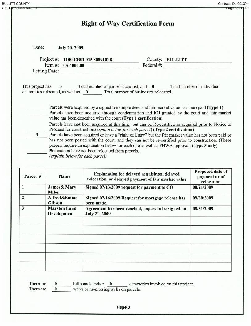
BULLITT COUNTYCB01 015 1494 B00025
Contract ID: 091304Page 53 of 140

UTILITY NOTES TO BE INCLUDED IN THE PROPOSAL SPECIAL NOTES FOR UTILITY CONSTRUCTION
IMPACT ON CONSTRUCTION
BULLITT COUNTY EMERGENCY BRIDGE REPLACEMENT ON KY-1494 @ (MP 5.542)
ITEM NO. 5-4000.00 The following Utility Companies have facilities in the general project area: SALT RIVER ELECTRIC Salt River Electric Company had an existing overhead facility that ran north to south, starting on the east side of KY-1494 and crossed KY-1494 from the power pole at approximate Sta. 26+72 to power pole at approximate Sta. 29+73. The relocated facility consists of the removal of the overhead cable between the power poles at Sta. 26+72 and 32+04, and removal of the power pole and anchor at approximate Sta. 29+73. This demolition relocation work was completed on May 27, 2009 as per Gary Pile of Salt River Electric Company. LOUISVILLE WATER COMPANY The Louisville Water Company had an existing 8” water main on the east side of KY-1494,
running north to south. The relocated 8” water main lies approximately 10’ to the east of the pre-existing main and ties into the existing main at approximate Sta.28+00 and at approximate Sta. 31+55. The pre-existing main will be abandoned in place. This facility will be relocated with the bridge replacement. The Contractor is advised to consult the plans and specifications for additional information regarding the relocation of said facilities. WINDSTREAM COMMUNICATIONS Windstream Communications has an existing underground facility that lies to the east of KY-
1494 and is clear of any construction. Windstream has another underground facility located on the west side of KY-1494 that ties to the pole at approximate Sta. 28+15. Said aerial crosses the creek, ties to a pole at approximate Sta. 29+53, and proceeds south underground. There exists a short section of underground cable in the stream bed between said poles. All facilities on the west side of KY-1494 are already abandoned. The relocation work consists of the removal of the two poles and anchors located on each side of the creek. This relocation work will be completed on August 19, 2009. As per Roger Redford of Windstream Communications.
SPECIAL CAUTION NOTE – PROTECTION OF UTILITIES
The location of utilities provided in the contract documents has been furnished by the facility owners and/or by reviewing record drawings and may not be accurate. It will be the roadway contractor’s responsibility to locate utilities before excavating by calling the various utility
BULLITT COUNTYCB01 015 1494 B00025
Contract ID: 091304Page 54 of 140

Bullitt County Item Number 5-4000.00
06/25/09 2
owners and by examining any supplemental information supplied by the Cabinet. If necessary, the roadway contractor shall determine the exact location and elevation of utilities by hand digging to expose utilities before excavating in the area of a utility. The cost for repair and any other associated costs for any damage to utilities caused by the roadway contractor’s operations shall be borne by the roadway contractor. The contractor is advised to contact the “BUD” one-call system 1-800-752-6007; the Contractor should be aware that owners of underground facilities are not required to be members of the “BUD” one-call system. It may be necessary for the Contractor to contact the County Court Clerk to determine what utility companies have facilities in the project area.
BULLITT COUNTYCB01 015 1494 B00025
Contract ID: 091304Page 55 of 140

1 of 7
BULLITT COUNTYCB01 015 1494 B00025
Contract ID: 091304Page 56 of 140
2 of 7
BULLITT COUNTYCB01 015 1494 B00025
Contract ID: 091304Page 57 of 140

3 of 7
BULLITT COUNTYCB01 015 1494 B00025
Contract ID: 091304Page 58 of 140

4 of 7
BULLITT COUNTYCB01 015 1494 B00025
Contract ID: 091304Page 59 of 140

5 of 7
BULLITT COUNTYCB01 015 1494 B00025
Contract ID: 091304Page 60 of 140

6 of 7
BULLITT COUNTYCB01 015 1494 B00025
Contract ID: 091304Page 61 of 140

7 of 7
BULLITT COUNTYCB01 015 1494 B00025
Contract ID: 091304Page 62 of 140

N O T I C E
DEPARTMENT OF THE ARMY CORPS OF ENGINEERS
And Kentucky Division of Water 401 WQC (NATIONWIDE PERMIT AUTHORIZATION)
PROJECT: Bullit County, Item No. 5-4000.00
The Section 404 activities for this project have been previously permitted under the authority of
the Department of the Army Nationwide Permit No. 14 “Linear Transportation Crossings” and
the Kentucky Division of Water as the project impacts are BELOW NOTIFICATION
THRESHOLDS. Specifically all stream impacts are below 300’, less that 0.10 acres and no
special aquatic sites will be impacted
In order for this authorization to be valid, the attached conditions must be followed. The
contractor shall post a copy of this Nationwide Permit in a conspicuous location at the project
site for the duration of construction and comply with the general conditions as required.
To more readily expedite construction, the contractor may elect to alter the design or perform the
work in a manner different from what was originally proposed and specified.
Prior to commencing such alternative work, the contractor shall obtain written permission from
the Division of Construction and the Corps of Engineers as well as the Kentucky Division of
Water (KDOW). A copy of any request to the Corps of Engineers/KDOW to alter this proposal
and subsequent responses shall be forwarded to the Division of Environmental Analysis, DA
Permit Coordinator, for office records and for informational purposes.
BULLITT COUNTYCB01 015 1494 B00025
Contract ID: 091304Page 63 of 140

BULLITT COUNTYCB01 015 1494 B00025
Contract ID: 091304Page 64 of 140

BULLITT COUNTYCB01 015 1494 B00025
Contract ID: 091304Page 65 of 140

BULLITT COUNTYCB01 015 1494 B00025
Contract ID: 091304Page 66 of 140

BULLITT COUNTYCB01 015 1494 B00025
Contract ID: 091304Page 67 of 140

BULLITT COUNTYCB01 015 1494 B00025
Contract ID: 091304Page 68 of 140

BULLITT COUNTYCB01 015 1494 B00025
Contract ID: 091304Page 69 of 140

BULLITT COUNTYCB01 015 1494 B00025
Contract ID: 091304Page 70 of 140

BULLITT COUNTYCB01 015 1494 B00025
Contract ID: 091304Page 71 of 140

BULLITT COUNTYCB01 015 1494 B00025
Contract ID: 091304Page 72 of 140

BULLITT COUNTYCB01 015 1494 B00025
Contract ID: 091304Page 73 of 140

BULLITT COUNTYCB01 015 1494 B00025
Contract ID: 091304Page 74 of 140

BULLITT COUNTYCB01 015 1494 B00025
Contract ID: 091304Page 75 of 140

BULLITT COUNTYCB01 015 1494 B00025
Contract ID: 091304Page 76 of 140

BULLITT COUNTYCB01 015 1494 B00025
Contract ID: 091304Page 77 of 140

BULLITT COUNTYCB01 015 1494 B00025
Contract ID: 091304Page 78 of 140

BULLITT COUNTYCB01 015 1494 B00025
Contract ID: 091304Page 79 of 140

BULLITT COUNTYCB01 015 1494 B00025
Contract ID: 091304Page 80 of 140

BULLITT COUNTYCB01 015 1494 B00025
Contract ID: 091304Page 81 of 140
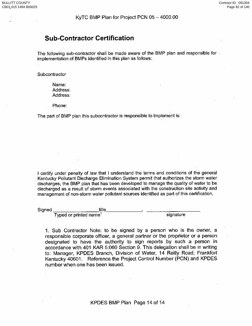
BULLITT COUNTYCB01 015 1494 B00025
Contract ID: 091304Page 82 of 140

BULLITT COUNTYCB01 015 1494 B00025
Contract ID: 091304Page 83 of 140

BULLITT COUNTYCB01 015 1494 B00025
Contract ID: 091304Page 84 of 140

Page 1
KENTUCKY TRANSPORTATION CABINETCOMMUNICATING ALL PROMISES (CAP)
ACTIVE
Page: 1SYP816219 JUN 2009
5Item No. 4000 TIM SHOWNProject Mgr.BULLITTCounty KY-1494 Route
1CAP #
17-JUN-09Date of Promise
Tom Wright KYTCPromise made to:
Project LimitsLocation of Promise
REMOVE GUARDRAIL
EXISTING GUARDRAIL, TERMINAL END SECTIONS, GUARDRAIL POST AND HARDWARE REMOVED UNDER BID ITEMNUMBER 2381 "REMOVE GUARDRAIL" SHALL BE SALVAGED AND DELIVERED TO MIDDLETOWN MAINTENANCEFACILITY, 313 N. ENGLISH STATION ROAD, LOUISVILLE, KY 40223.
CAP Description
-
BULLITT COUNTYCB01 015 1494 B00025
Contract ID: 091304Page 85 of 140

PART II
SPECIFICATIONS AND STANDARD DRAWINGS
BULLITT COUNTYCB01 015 1494 B00025
Contract ID: 091304Page 86 of 140

SPECIFICATIONS REFERENCE Any reference in the plans or proposal to the Standard Specifications for Road and Bridge Construction, Edition of 2004, and Standard Drawings, Edition of 2000 are superseded by Standard Specifications for Road and Bridge Construction, Edition of 2008 and Standard Drawings, Edition of 2003 with the 2008 Revision.
BULLITT COUNTYCB01 015 1494 B00025
Contract ID: 091304Page 87 of 140

Supplemental Specifications to The Standard Specifications for Road and Bridge Construction, 2008 Edition
(Effective with the July 24, 2009 Letting)
SUBSECTION:
REVISION: 101.02 Abbreviations. Insert the following abbreviation and text into the section: KEPSC Kentucky Erosion Prevention and Sediment Control
SUBSECTION: 101.03 Definitions. REVISION: Replace the definition for Specifications – Special Provisions with the following:
Additions and revisions to the Standard and Supplemental Specifications covering conditions peculiar to and individual project.
SUBSECTION: 102.07.01 General. REVISION: Replace the first sentence with the following:
Submit the Bid Proposal on forms furnished on the Department internet website (http://transportation.ky.gov/contract/), including the Bid Packet and disk created from the Expedite Bidding Program.
SUBSECTION: 102.07.02 Computer Bidding. REVISION: Replace the first paragraph with the following:
Subsequent to ordering a Bid Proposal for a specific project, use the Department’s Expedite Bidding Program on the internet website of the Department of Highways, Division of Construction Procurement (http://transportation.ky.gov/contract/). Download the bid file from the Department’s website to prepare a Bid Proposal for submission to the Department. Include the completed Bid Packet produced by the Expedite Bidding Program and submit it along with the disk created by said program. Replace the second paragraph with the following: In case of a dispute, the printed Bid Proposal and bid item sheets created by the Expedite Bidding Program take precedence over any bid submittal.
SUBSECTION: 102.08 IRREGULAR BID PROPOSALS. REVISION: Replace point four of the first paragraph with the following:
4) fails to submit a disk created from the Expedite Bidding Program.
Replace point one of the second paragraph with the following:
1) when the Bid Proposal is on a form other than that furnished by the Department or printed from other than the Expedite Bidding Program, or when the form is altered or any part is detached; or
SUBSECTION: 103.02 AWARD OF CONTRACT.
REVISION: Replace the first sentence of the third paragraph with the following: The Department will normally award the Contract within 10 working days after the date of receiving Bid Proposals unless the Department deems it best to hold the Bid Proposals of any or all bidders for a period not to exceed 60 calendar days for final disposition of award.
Page 1 of 15
BULLITT COUNTYCB01 015 1494 B00025
Contract ID: 091304Page 88 of 140

Supplemental Specifications to The Standard Specifications for Road and Bridge Construction, 2008 Edition
(Effective with the July 24, 2009 Letting)
SUBSECTION: 105.12 FINAL INSPECTION AND ACCEPTANCE OF WORK.
REVISION: Insert the following paragraphs after the first paragraph: Notify the Engineer when all electrical items are complete. A notice of the electrical work completion shall be made in writing to the Contractor. Electrical items will be inspected when the electrical work is complete and are not subject to waiting until the project as a whole has been completed. The Engineer will notify the Division of Traffic Operations within 3 days that all electrical items are complete and ready for a final inspection. A final inspection will be completed within 90 days after the Engineer notifies the Division of Traffic Operations of the electrical work completion. Energize all electrical items prior to notifying the Engineer that all electrical items are complete. Electrical items must remain operational until the Division of Traffic Operations has inspected and accepted the electrical portion of the project. Payment for the electrical service is the responsibility of the Contractor from the time the electrical items are energized until the Division of Traffic Operations has accepted the work. Complete all corrective work within 90 calendar days of receiving the original electrical inspection report. Notify the Engineer when all corrective work is complete. The Engineer will notify the Division of Traffic Operations that the corrective work has been completed and the project is ready for a follow-up inspection. Upon re-inspection, if additional corrective work is required, complete within the same 90 calendar day allowance. The Department will not include time between completion of the corrective work and the follow up electrical inspection(s). The 90 calendar day allowance is cumulative regardless of the number of follow-up electrical inspections required. The Department will assume responsibility for the electrical service on a project once the Division of Traffic Operations gives final acceptance of the electrical items on the project. The Department will also assume routine maintenance of those items. Any damage done to accepted electrical work items by other Contractors shall be the responsibility of the Prime Contractor. The Department will not be responsible for repairing damage done by other contractors during the construction of the remaining project. Failure to complete the electrical corrective work within the 90 calendar day allowance will result in penalties assessed to the project. Penalties will be assessed at ½ the rate of liquidated damages established for the contract. Delete the fifth paragraph from the section.
SUBSECTION: 105.13 CLAIM RESOLUTION PROCESS. REVISION: Delete the last paragraph from the section.
SUBSECTION: 106.10 FIELD WELDER CERTIFICATION REQUIREMENTS. REVISION: Insert the following sentence before the first sentence of the first paragraph:
All field welding must be performed by a certified welder unless otherwise noted.
SUBSECTION: 112.03.11 Temporary Pavement Markings. PART: B) Placement and Removal of Temporary Striping.
REVISION: Replace the 2nd sentence of the fist paragraph with the following: On interstates and parkways, and other roadways approved by the State Highway Engineer, install pavement striping that is 6 inches in width.
SUBSECTION: 112.03.12 Project Traffic Coordinator (PTC). REVISION: Add the following at the end of the subsection:
After October 1, 2008 the Department will require the PTC to have successfully completed the applicable qualification courses. Personnel that have not successfully completed the applicable courses by that date will not be considered qualified. Prior to October 1, 2008, conform to Subsection 108.06 A) and ensure the designated PTC has sufficient skill and experience to properly perform the task.
Page 2 of 15
BULLITT COUNTYCB01 015 1494 B00025
Contract ID: 091304Page 89 of 140

Supplemental Specifications to The Standard Specifications for Road and Bridge Construction, 2008 Edition
(Effective with the July 24, 2009 Letting)
SUBSECTION: 206.03.02 Embankment REVISION: Replace the last paragraph with the following:
When rock roadbed is specified, construct the upper 2 feet of the embankment according to Subsection 204.03.09 A).
SUBSECTION: 213.03.03 Inspection and Maintenance. REVISION: Insert the following paragraph after the second paragraph:
When the Contractor is required to obtain the KPDES permit, it is their responsibility to ensure compliance with the inspection and maintenance requirements of the permit. The Engineer will perform verification inspections a minimum of once per month and within 7 days of a ½ inch or greater rainfall event. The Engineer will document these inspections using Form TC 63-61 A. The Engineer will provide copies of the inspection only when improvements to the BMP’s are required. Verification inspections performed by the Engineer do not relieve the Contractor of any responsibility for compliance with the KPDES permit. Initiate corrective action within 24 hours of any noted deficiency and complete the work within 5 days.
SUBSECTION: 213.03.05 Temporary Control Measures. PART: F) Temporary Mulch.
REVISION: Replace the last sentence with the following: Place temporary mulch to an approximate 2-inch loose depth (2 tons per acre) and anchor it into the soil by mechanically crimping it into the soil surface or applying tackifier to provide a protective cover. Regardless of the anchoring method used, ensure the protective cover holds until disturbance is required or permanent controls are in installed.
SUBSECTION: 303.05 PAYMENT. REVISION: Replace the second paragraph of the section with the following:
The Department will make payment for Drainage Blanket-Type II (ATDB) according to the Lot Pay Adjustment Schedule for Specialty Mixtures in Section 402.
SUBSECTION: 401.02.04 Special Requirements for Dryer Drum Plants. PART: F) Production Quality Control.
REVISION: Replace the first sentence with the following: Stop mixing operations immediately if, at any time, a failure of the automatic electronic weighing system of the aggregate feed, asphalt binder feed, or water injection system control occurs.
SUBSECTION: 401.02.04 Special Requirements for Dryer Drum Plants. REVISION: Add the following:
Part G) Water Injection System. Provided each system has prior approval as specified in Subsection 402.01.01, the Department will allow the use of water injection systems for purposes of foaming the asphalt binder and lowering the mixture temperature for production of Warm Mix Asphalt (WMA). Ensure the equipment for water injection meets the following requirements:
1) Injection equipment computer controls are automatically coupled to the plants controls (manual operation is not permitted);
2) Injection equipment has variable controls that introduce water ratios based on production rates of mixtures;
3) Injects water into the flow of asphalt binder prior to contacting the aggregate; 4) Provides alarms on the water injection system that operate when the flow of water is
interrupted or deviates from the prescribed water rate.
SUBSECTION: 401.03.01 Preparation of Mixtures. REVISION: Replace the last sentence of the second paragraph with the following:
Do not use asphalt binder while it is foaming in a storage tank.
Page 3 of 15
BULLITT COUNTYCB01 015 1494 B00025
Contract ID: 091304Page 90 of 140

Supplemental Specifications to The Standard Specifications for Road and Bridge Construction, 2008 Edition
(Effective with the July 24, 2009 Letting)
SUBSECTION: 401.03.01 Preparation of Mixtures.
REVISION: Replace the third paragraph and Mixing and Laying Temperature table with the following: Maintain the temperature of the component materials and asphalt mixture within the ranges listed in the following table:
MIXING AND LAYING TEMPERATURES (°F)
Material Minimum Maximum
Aggregates 240 330 Aggregates used with Recycled Asphalt Pavement (RAP)
240 ⎯
Asphalt Binders PG 64-22 230 330 PG 76-22 285 350 Asphalt Mixtures at Plant PG 64-22 HMA 250 330 (Measured in Truck)
PG 76-22 HMA PG 64-22 WMA PG 76-22 WMA
310 230 250
350 275 300
Asphalt Mixtures at Project PG 64-22 HMA 230 330 (Measured in Truck PG 76-22 HMA 300 350 When Discharging) PG 64-22 WMA
PG 76-22 WMA 210 240
275 300
SUBSECTION: 402.01 Description. REVISION: Replace the paragraph with the following:
Provide the process control and acceptance testing of all classes and types of asphalt mixtures which may be furnished either as hot mix asphalt (HMA) or warm mix asphalt (WMA) produced with water injection systems.
SUBSECTION 402.01.01 Warm Mix Asphalt (WMA) Evaluation and Approval. REVISION: Add the following subsection:
402.01.01 Warm Mix Asphalt (WMA) Evaluation and Approval. The Department will evaluate trial production of WMA by use of a water injection system provided the system is installed according to the manufacturer’s requirements and satisfies the requirements of Section 401. Evaluation will include production and placement of WMA to demonstrate adequate mixture quality including volumetric properties and density by Option A as specified in Subsection 402.03.02 D). Do not place WMA for evaluation on Department projects. Provided production and placement operations satisfy the applicable quality levels, the Department will approve WMA production on Department projects using the water injection system as installed on the specific asphalt mixing plant evaluated.
SUBSECTION: 402.05.02 Asphalt Mixtures and Mixtures With RAP. REVISION: Replace Subsection Title as below:
402.05.02 Asphalt Mixtures, HMA and WMA, Including Mixtures With RAP.
SUBSECTION: 402.05.02 Asphalt Mixtures, HMA and WMA, Including Mixtures With RAP. REVISION: Replace the paragraph with the following:
The Department will pay for the mixture at the Contract unit bid price and apply a Lot Pay Adjustment for each lot placed based on the degree of compliance with the specified tolerances. Using the appropriate Lot Pay Adjustment Schedule, the Department will assign a pay value for the applicable properties within each sublot and average the sublot pay values to determine the pay value for a given property for each lot. The Department will apply the Lot Pay Adjustment for each lot to a defined unit price of $50.00 per ton. The Department will calculate the Lot Pay Adjustment using all possible incentives and disincentives but will not allow the overall pay value for a lot to exceed 1.00.
Page 4 of 15
BULLITT COUNTYCB01 015 1494 B00025
Contract ID: 091304Page 91 of 140

Supplemental Specifications to The Standard Specifications for Road and Bridge Construction, 2008 Edition
(Effective with the July 24, 2009 Letting)
SUBSECTION: 402.05.02 Asphalt Mixtures, HMA and WMA, Including Mixtures With RAP. PART: C) Conventional and RAP Mixtures Placed on Shoulders.
REVISION: Replace title with the following: HMA, WMA, and RAP Mixtures Placed on Shoulders.
SUBSECTION: 402.05.02 Asphalt Mixtures, HMA and WMA, Including Mixtures With RAP. PART: D) Conventional and RAP Mixtures Placed Monolithically as Asphalt Pavement Wedge.
REVISION: Replace the title with the following: HMA, WMA, and RAP Mixtures Placed Monolithically as Asphalt Pavement Wedge.
SUBSECTION: 402.05.02 Asphalt Mixtures, HMA and WMA, Including Mixtures With RAP. PART: Lot Pay Adjustment Schedule, Compaction Option A, Base and Binder Mixtures
TABLES: VMA REVISION: Replace the VMA table with the following:
VMA Pay Value Deviation
From Minimum 1.00 ≥ min. VMA 0.95 0.1-0.5 below min. 0.90 0.6-1.0 below min.
(1) > 1.0 below min.
SUBSECTION: 402.05.02 Asphalt Mixtures, HMA and WMA, Including Mixtures With RAP. PART: Lot Pay Adjustment Schedule, Compaction Option A, Surface Mixtures
TABLES: VMA REVISION: Replace the VMA table with the following:
VMA Pay Value Deviation
From Minimum
1.00 ≥ min. VMA 0.95 0.1-0.5 below min.0.90 0.6-1.0 below min.
(1) > 1.0 below min.
Page 5 of 15
BULLITT COUNTYCB01 015 1494 B00025
Contract ID: 091304Page 92 of 140

Supplemental Specifications to The Standard Specifications for Road and Bridge Construction, 2008 Edition
(Effective with the July 24, 2009 Letting)
SUBSECTION: 402.05.02 Asphalt Mixtures, HMA and WMA, Including Mixtures With RAP. PART: Lot Pay Adjustment Schedule, Compaction Option B Mixtures
TABLE: VMA REVISION: Replace the VMA table with the following:
VMA Pay Value Deviation
From Minimum
1.00 ≥min. VMA 0.95 0.1-0.5 below min.0.90 0.6-1.0 below min.
(2) > 1.0 below min.
SUBSECTION: 403.03.03 Preparation of Mixture. PART: C) Mix Design Criteria.
NUMBER: 1) Preliminary Mix Design. REVISION: Replace the last two sentences of the paragraph and table with the following:
Complete the volumetric mix design at the appropriate number of gyrations as given in the table below
for the number of 20-year ESAL’s. The Department will define the relationship between ESAL classes, as given in the bid items for Superpave mixtures, and 20-year ESAL ranges as follows:
Number of Gyrations
Class ESAL’s (millions) Ninitial Ndesign Nmax2 < 3.0 6 50 75 3 3.0 to < 30.0 7 75 115 4 > 30.0 8 100 160
SUBSECTION: 403.03.09 Leveling and Wedging, and Scratch Course. PART: A) Leveling and Wedging.
REVISION: Replace the first sentence of the first paragraph with the following: Conform to the gradation requirements (control points) of AASHTO M 323 for base, binder, or surface as the Engineer directs.
SUBSECTION: 403.03.09 Leveling and Wedging, and Scratch Course. PART: B) Scratch Course.
REVISION: Replace the second sentence of the first paragraph with the following: Conform to the gradation requirements (control points) of AASHTO M 323 for base, binder, or surface as the Engineer directs.
SUBSECTION: 407.01 DESCRIPTION. REVISION: Replace the first sentence of the paragraph with the following:
Construct a pavement wedge composed of a hot-mixed or warm-mixed asphalt mixture.
SUBSECTION: 409.01 DESCRIPTION. REVISION: Replace the first sentence of the paragraph with the following:
Use reclaimed asphalt pavement (RAP) from Department projects or other approved sources in hot mix asphalt (HMA) or warm mix asphalt (WMA) provided mixture requirements are satisfied.
SUBSECTION: 410.01 DESCRIPTION. REVISION: Delete the second sentence of the paragraph.
Page 6 of 15
BULLITT COUNTYCB01 015 1494 B00025
Contract ID: 091304Page 93 of 140

Supplemental Specifications to The Standard Specifications for Road and Bridge Construction, 2008 Edition
(Effective with the July 24, 2009 Letting)
SUBSECTION: 410.03.01 Corrective Work. REVISION: Replace the last sentence of the paragraph with the following:
Provide a final surface comparable to the adjacent pavement that does not require corrective work in respect to texture, appearance, and skid resistance.
SUBSECTION: 410.03.02 Ride Quality. PART: B) Requirements.
NUMBER: 1) Category A. REVISION: Replace the last sentence of the first paragraph with the following:
At the Department’s discretion, a pay deduction of $1200 per 0.1-lane-mile section may be applied in lieu of corrective work.
SUBSECTION: 410.03.02 Ride Quality. PART: B) Requirements.
NUMBER: 2) Category B. REVISION: Replace the second and third sentence of the first paragraph with the following:
When the IRI is greater than 90 for a 0.1-mile section, perform corrective work, or remove and replace the pavement to achieve the specified IRI. At the Department’s discretion, a pay deduction of $750 per 0.1-lane-mile section may be applied in lieu of corrective work.
SUBSECTION: 410.05 PAYMENT. REVISION: Add the following sentence to the end of the first paragraph:
The sum of the pay value adjustments for ride quality shall not exceed $0 for the project as a whole.
SUBSECTION: 413.05.02 CL3 SMA BASE 1.00D PG76-22. REVISION: Insert the following sentence between the first and second sentence of the first paragraph:
The Department will calculate the Lot Pay Adjustment using all possible incentives and disincentives but will not allow the overall pay value for a lot to exceed 1.00.
SUBSECTION: 413.05.02 CL3 SMA BASE 1.00D PG 76-22. TABLE: JOINT DENSITY TABLE
REVISION: Replace the joint density table with the following:
LANE DENSITY Pay Value Test Result (%)
1.05 95.0-96.5 1.00 93.0-94.9 0.95 92.0-92.9 or 96.6-97.00.90 91.0-91.9 or 97.1-97.5
(1) < 91.0 or > 97.5
SUBSECTION: 413.05.03 CL3 SMA SURF 0.50A PG76-22 and CL3 SMA SURF 0.38A PG76-22. REVISION: Insert the following sentence between the first and second sentence of the first paragraph:
The Department will calculate the Lot Pay Adjustment using all possible incentives and disincentives but will not allow the overall pay value for a lot to exceed 1.00.
Page 7 of 15
BULLITT COUNTYCB01 015 1494 B00025
Contract ID: 091304Page 94 of 140

Supplemental Specifications to The Standard Specifications for Road and Bridge Construction, 2008 Edition
(Effective with the July 24, 2009 Letting)
SUBSECTION: 413.05.03 CL3 SMA SURF 0.50A PG76-22 and CL3 SMA SURF 0.38A PG76-22. TABLE: JOINT DENSITY TABLE
REVISION: Replace the joint density table with the following:
DENSITY Pay Value Lane Density
Test Result (%) Joint Density
Test Result (%) 1.05 95.0-96.5 92.0-96.0 1.00 93.0-94.9 90.0-91.9 0.95 92.0-92.9 or 96.6-97.0 89.0-89.9 or 96.1-96.5 0.90 91.0-91.9 or 97.1-97.5 88.0-88.9 or 96.6-97.0 0.75 ---- < 88.0 or > 97.0
(1) < 91.0 or > 97.5 ----
SUBSECTION: 501.05.02 Ride Quality. REVISION: Add the following sentence to the end of the first paragraph:
The sum of the pay value adjustments for the ride quality shall not exceed $0 for the project as a whole.
SUBSECTION: 505.03.04 Detectable Warnings. REVISION: Replace the first sentence with the following:
Install detectable warning pavers at all sidewalk ramps and on all commercial entrances according to the Standard Drawings.
SUBSECTION: 505.04.04 Detectable Warnings. REVISION: Replace the paragraph with the following:
The Department will measure the quantity in square feet. All retrofit applications for maintenance projects will require the removal of existing sidewalks to meet the requirements of the standard drawings applicable to the project. The cost associated with the removal of the existing sidewalk will be incidental to the detectable warnings bid item or incidental to the bid item for the construction of the concrete sidewalk unless otherwise noted.
SUBSECTION: 505.05 PAYMENT. REVISION: Add the following to the bid item table:
Code Pay Item Pay Unit23158ES505 Detectable Warnings Square Foot
SUBSECTION: 509.01 DESCRIPTION. REVISION: Replace the second paragraph with the following:
The Department may allow the use of similar units that conform to the National Cooperative Highway Research Program (NCHRP) 350 Test Level 3 (TL-3) requirements and the typical features depicted by the Standard Drawings. Obtain the Engineers approval prior to use. Ensure the barrier wall shape, length, material, drain slot dimensions and locations typical features are met and the reported maximum deflection is 3 feet or less from the NCHRP 350 TL-3 for Test 3 – 11 (pickup truck impacting at 60 mph at a 25-degree angle.)
SUBSECTION: 601.03.02 Concrete Producer Responsibilities. REVISION: Add the following to the first paragraph:
If a concrete plant becomes unqualified during a project and there are no other qualified plants in the region, the Department will provide qualified personnel to witness and ensure the producer follows the required specifications. The Department will assess the Contractor a $100 per hour charge for this service.
Page 8 of 15
BULLITT COUNTYCB01 015 1494 B00025
Contract ID: 091304Page 95 of 140

Supplemental Specifications to The Standard Specifications for Road and Bridge Construction, 2008 Edition
(Effective with the July 24, 2009 Letting)
SUBSECTION: 606.02.11 Coarse Aggregate. REVISION: Replace with the following:
Conform to Section 805, size No. 8 or 9-M.
SUBSECTION: 609.04.06 Joint Sealing. REVISION: Replace Subsection 601.04 with the following:
Subsection 606.04.08.
SUBSECTION: 609.05 Payment. REVISION: Replace the Pay Unit for Joint Sealing with the following:
See Subsection 606.05.
SUBSECTION: 701.03.06 Initial Backfill. REVISION: Replace the first sentence of the last paragraph with the following:
When the Contract specifies, perform quality control testing to verify compaction according to KM 64-512.
SUBSECTION: 701.03.08 Testing of Pipe. REVISION: Replace and rename the subsection with the following:
701.03.08 Inspection of Pipe. The engineer will visually inspect all pipe. The Department will require camera/video inspection on a minimum of 50 percent of the linear feet of all installed pipe structures. Conduct camera/video inspection according to KM 64-114. The pipe to be installed under pavement will be selected first. If the total linear feet of pipe under pavement is less than 50 percent of the linear feet of all pipe installed, the Engineer will randomly select installations from the remaining pipe structures on the project to provide for the minimum inspection requirement. The pipe will be selected in complete runs (junction-junction or headwall-headwall) until the total linear feet of pipe to be inspected is at least 50 percent of the total linear feet of all installed pipe on the project. Unless the Engineer directs otherwise, schedule the inspections no sooner than 30 days after completing the installation and completion of earthwork to within 1 foot of the finished subgrade. When final surfacing conflicts with the 30-day minimum, conduct the inspections prior to placement of the final surface. The contractor must ensure that all pipe are free and clear of any debris so that a complete inspection is possible. Notify the Engineer immediately if distresses or locations of improper installation are discovered. When camera testing shows distresses or improper installation in the installed pipe, the Engineer may require additional sections to be tested. Provide the video and report to the Engineer when testing is complete in accordance with KM 64-114. Pipes that exhibit distress or signs of improper installation may necessitate repair or removal as the Engineer directs. These signs include, but are not limited to: deflection, cracking, joint separation, sagging or other interior damage. If corrugated metal or thermoplastic pipes exceed the deflection and installation thresholds indicated in the table below, provide the Department with an evaluation of each location conducted by a Professional Engineer addressing the severity of the deflection, structural integrity, environmental conditions, design service life, and an evaluation of the factor of safety using Section 12, “Buried Structures and Tunnel Liners,” of the AASHTO LRFD Bridge Design Specifications. Based on the evaluation, the Department may allow the pipe to remain in place at a reduced unit price as shown in the table below. Provide 5 business days for the Department to review the evaluation. When the pipe shows deflection of 10 percent or greater, remove and replace the pipe. When the camera/video or laser inspection results are called into question, the Department may require direct measurements or mandrel testing. The Cabinet may elect to conduct Quality Assurance verifications of any pipe inspections.
Page 9 of 15
BULLITT COUNTYCB01 015 1494 B00025
Contract ID: 091304Page 96 of 140

Supplemental Specifications to The Standard Specifications for Road and Bridge Construction, 2008 Edition
(Effective with the July 24, 2009 Letting)
SUBSECTION: 701.04.07 Testing. REVISION: Replace and rename the subsection with the following:
701.04.07 Pipeline Video Inspection. The Department will measure the quantity in linear feet along the pipe invert of the structure inspected. When inspection above the specified 50 percent is performed due to a disagreement or suspicion of additional distresses and the Department is found in error, the Department will measure the quantity as Extra Work according to Subsection 104.03. However, if additional distresses or non-conformance is found, the Department will not measure the additional inspection for payment.
SUBSECTION: 701.05 PAYMENT. REVISION: Add the following pay item to the list of pay items:
Code Pay Item Pay Unit 23131ER701 Pipeline Video Inspection Linear Foot
SUBSECTION: 701.05 PAYMENT TABLE: PIPE DEFLECTION DETERMINED BY CAMERA TESTING
REVISION: Replace this table with the following table and note:
PIPE DEFLECTION Amount of Deflection (%) Payment 0.0 to 5.0 100% of the Unit Bid Price 5.1 to 9.9 50% of the Unit Bid Price (1)
10 or greater Remove and Replace
(1) Provide Structural Analysis as indicated above. Based on the structural analysis, pipe may be allowed to remain in place at the reduced unit price.
SUBSECTION: 701.05 PAYMENT TABLE: PIPE DEFLECTION DETERMINED BY MANDREL TESTING
REVISION: Delete this table. SUBSECTION: 713.02.01 Paint.
REVISION: Replace with the following: Conform to Section 842 and Section 846.
SUBSECTION: 713.03 CONSTRUCTION. REVISION: Replace the first sentence of the second paragraph with the following:
On interstates and parkways, and other routes approved by the State Highway Engineer, install pavement striping that is 6 inches in width.
SUBSECTION: 713.03.03 Paint Application. REVISION: Replace the second paragraph with the following table:
Material Paint Application Rate Glass Beads Application Rate 4 inch waterborne paint Min. of 16.5 gallons/mile Min. of 6 pounds/gallon 6 inch waterborne paint Min. of 24.8 gallons/mile Min. of 6 pounds/gallon 6 inch durable waterborne paint Min. of 36 gallons/mile Min. of 6 pounds/gallon
Page 10 of 15
BULLITT COUNTYCB01 015 1494 B00025
Contract ID: 091304Page 97 of 140

Supplemental Specifications to The Standard Specifications for Road and Bridge Construction, 2008 Edition
(Effective with the July 24, 2009 Letting)
SUBSECTION: 713.03.04 Marking Removal. REVISION: Replace the last sentence of the paragraph wit the following:
Vacuum all marking material and removal debris concurrently with the marking removal operation.
SUBSECTION: 713.05 PAYMENT. REVISION: Insert the following codes and pay items below the Pavement Striping – Permanent Paint:
Code Pay Item Pay Unit 23159EN Durable Waterborne Marking – 6 IN W Linear Foot 23160EN Durable Waterborne Marking – 6 IN Y Linear Foot
SUBSECTION: 714.03 CONSTRUCTION. REVISION: Insert the following paragraph at the end of the third paragraph:
Use Type I Tape for markings on bridge decks, JPC pavement and JPC intersections. Thermoplastic should only be used for markings on asphalt pavement
SUBSECTION: 714.03.07 Marking Removal. REVISION: Replace the third sentence of the paragraph with the following:
Vacuum all marking material and removal debris concurrently with the marking removal operation.
SUBSECTION: 716.01 DESCRIPTION. REVISION: Insert the following after the first sentence:
Energize lighting as soon as it is fully functional and ready for inspection. Ensure that lighting remains operational until the Division of Traffic Operations has provided written acceptance of the electrical work.
SUBSECTION: 716.02.01 Roadway Lighting Materials. REVISION: Replace the third sentence of the paragraph with the following:
Submit for material approval an electronic file of descriptive literature, drawings, and any requested design data.
SECTION: 717 – THERMOPLASTIC INTERSECTION MARKINGS. REVISION: Replace the section name with the following:
INTERSECTION MARKINGS.
SUBSECTION: 717.01 DESCRIPTION: REVISION: Replace the paragraph with the following:
Furnish and install thermoplastic or Type I tape intersection markings (Stop Bars, Crosswalks, Turn Arrows, etc.) Thermoplastic markings may be installed by either a machine applied, screed extrusion process or by applying preformed thermoplastic intersection marking material.
SUBSECTION: 717.02 MATERIALS AND EQUIPMENT. REVISION: Insert the following subsection:
717.02.06 Type I Tape. Conform to Section 836.
SUBSECTION: 717.03.03 Application. REVISION: Insert the following part to the subsection:
B) Type I Tape Intersection Markings. Apply according to the manufacturer’s recommendations. Cut all tape at pavement joints when applied to concrete surfaces.
Page 11 of 15
BULLITT COUNTYCB01 015 1494 B00025
Contract ID: 091304Page 98 of 140

Supplemental Specifications to The Standard Specifications for Road and Bridge Construction, 2008 Edition
(Effective with the July 24, 2009 Letting)
Page 12 of 15
SUBSECTION: 717.03.05 Proving Period. PART: A) Requirements.
REVISION: Insert the following to this section: 2) Type I Tape. During the proving period, ensure that the pavement marking material shows no signs of failure due to blistering, excessive cracking, bleeding, staining, discoloration, oil content of the pavement materials, drippings, chipping, spalling, poor adhesion to the pavement, loss of retroreflectivity, vehicular damage, and normal wear. Type I Tape is manufactured off site and warranted by the manufacturer to meet certain retroreflective requirements. As long as the material is adequately bonded to the surface and shows no signs of failure due to the other items listed in Subsection 714.03.06 A) 1), retroreflectivity readings will not be required. In the absence of readings, the Department will accept tape based on a nighttime visual observation.
SUBSECTION: 717.03.06 Marking Removal. REVISION: Replace the third sentence of the paragraph with the following:
Vacuum all marking material and removal debris concurrently with the marking removal operation.
SUBSECTION: 717.05 PAYMENT. REVISION: Insert the following bid item codes:
Code Pay Unit Pay Item 06563 Pave Marking – R/R X Bucks 16 IN Linear Foot 20782NS714 Pave Marking Thermo – Bike Each 23251ES717, 23264ES717 Pave Mark TY I Tape X-Walk, Size Linear Foot 23252ES717, 23265ES717 Pave Mark TY I Tape Stop Bar, Size Linear Foot 23253ES717 Pave Mark TY I Tape Cross Hatch Square Foot 23254ES717 Pave Mark TY I Tape Dotted Lane Extension Linear Foot 23255ES717 Pave Mark TY I Tape Arrow, Type Each 23268ES717-23270ES717 23256ES717 Pave Mark TY I Tape- ONLY Each 23257ES717 Pave Mark TY I Tape- SCHOOL Each 23266ES717 Pave Mark TY 1 Tape R/R X Bucks-16 IN Linear Foot 23267ES717 Pave Mark TY 1 Tape-Bike Each
SUBSECTION: 805.01 GENERAL. REVISION: Replace the second paragraph with the following:
The Department’s List of Approved Materials includes the Aggregate Source List, the list of Class A and Class B Polish-Resistant Aggregate Sources, and the Concrete Restriction List.
SUBSECTION: 805.04 CONCRETE. REVISION: Replace the “AASHTO T 160” reference in first sentence of the third paragraph with “KM 64-629”
SUBSECTION: 805.15 GRADATION ACCEPTANCE OF NON-SPECIFICATION COARSE AGGREGATE.
TABLE: AGGREGATE SIZE USE PART: Cement Concrete Structures and Incidental Construction
REVISION: Replace “9-M for Waterproofing Overlays” with “8 or 9-M for Waterproofing Overlays”
BULLITT COUNTYCB01 015 1494 B00025
Contract ID: 091304Page 99 of 140

Supp
lem
enta
l Spe
cific
atio
ns to
The
Sta
ndar
d Sp
ecifi
catio
ns
for
Roa
d an
d B
ridg
e C
onst
ruct
ion,
200
8 E
ditio
n (E
ffec
tive
with
the
July
24,
200
9 Le
tting
)
Page
13
of 1
5
SUB
SEC
TIO
N:
805.
15 G
RA
DA
TIO
N A
CC
EPTA
NC
E O
F N
ON
-SPE
CIF
ICA
TIO
N C
OA
RSE
AG
GR
EGA
TE.
RE
VIS
ION
: R
epla
ce th
e “S
IZES
OF
CO
AR
SE A
GG
REG
ATE
S” ta
ble
in w
ith th
e fo
llow
ing:
(1)
Gra
datio
n pe
rfor
med
by
wet
siev
e K
M 6
4-62
0 or
AAS
HTO
T 1
1/T
27.
(2)
Size
s sho
wn
for c
onve
nien
ce a
nd a
re n
ot to
be
cons
ider
ed a
s coa
rse
aggr
egat
es.
(3)
Nom
inal
Max
imum
Siz
e is
the
larg
est s
ieve
on
the
grad
atio
n ta
ble
for a
n ag
greg
ate
size
on
whi
ch a
ny m
ater
ial m
ay b
e re
tain
ed.
Not
e: T
he D
epar
tmen
t will
allo
w b
lend
ing
of sa
me
sour
ce/s
ame
type
agg
rega
te w
hen
prec
ise
proc
edur
es a
re u
sed
such
as c
old
feed
, bel
t, or
equ
ival
ent a
nd
com
bini
ng o
f siz
es o
r typ
es o
f agg
rega
te u
sing
the
wei
gh h
oppe
r at c
oncr
ete
plan
ts o
r con
trolle
d fe
ed b
elts
at t
he p
ugm
ill to
obt
ain
desi
gnat
ed si
zes.
SIZE
S O
F C
OA
RSE
AG
GR
EG
AT
ES
Si
eve
AM
OU
NTS
FIN
ER T
HA
N E
AC
H L
AB
OR
ATO
RY
SIE
VE
(SQ
UA
RE
OPE
NIN
GS)
PER
CEN
TAG
E B
Y W
EIG
HT
Agg
rega
te S
ize
Nom
inal
(3)
Max
imum
A
ggre
gate
Siz
e
4 in
ch
3 1/
2 in
ch
3 in
ch
2 1/
2 in
ch
2 in
ch
1 1/
2 in
ch
1 in
ch
3/4
inch
1/
2 in
ch
3/8
inch
N
o. 4
N
o. 8
N
o. 1
6 N
o. 3
0 N
o. 1
00
No.
200
1 3
½ in
ch
100
90-1
00
25
-60
0-
15
0-
5
2 2
½ in
ch
100
90-1
00
35-7
0 0-
15
0-
5
23
2 in
ch
100
40
-90
0-
15
0-
5
3 2
inch
100
90-1
0035
-70
0-15
0-5
357
2 in
ch
10
0 95
-100
35
-70
10
-30
0-
5
4 1
½ in
ch
100
90-1
00
20-5
5 0-
15
0-
5
467
1 ½
inch
10
0 95
-100
35-7
0
10-3
0 0-
5
5 1
inch
100
90-1
0020
-55
0-10
0-
5
57
1 in
ch
10
0 95
-100
25
-60
0-
10
0-5
610
1 in
ch
10
0 85
-100
40
-75
15
-40
67
3/4
inch
10
0 90
-100
20-5
5 0-
10
0-5
68
3/4
inch
10
0 90
-100
30-6
5 5-
25
0-10
0-
5
710
3/4
inch
10
0 80
-100
30-7
5 0-
30
78
1/2
inch
100
90-1
00
40-7
5 5-
25
0-10
0-
5
8 3/
8 in
ch
100
85-1
00
10-3
0 0-
10
0-5
9-M
3/
8 in
ch
100
75-1
00
0-25
0-
5
10(2
)N
o. 4
100
85-1
00
10
-30
11(2
)N
o. 4
100
40-9
0 10
-40
0-5
DEN
SE G
RA
DED
A
GG
REG
ATE
(1)
3/4
inch
10
0 70
-100
50-8
0 30
-65
10-4
0
4-13
CR
USH
ED
STO
NE
BA
SE (1
)1
½ in
ch
10
0
90-1
00
60
-95
30
-70
15-5
5
5-
20
0-
8
BULLITT COUNTYCB01 015 1494 B00025
Contract ID: 091304Page 100 of 140

Supplemental Specifications to The Standard Specifications for Road and Bridge Construction, 2008 Edition
(Effective with the July 24, 2009 Letting)
SUBSECTION: 805.16 SAMPLING AND TESTING. REVISION: Replace the “AASHTO T 160” method with the “KM 64-629” method for the Concrete Beam Expansion
Test. Replace the “ASTM D 3042” method with the “KM 64-625” method for Insoluble Residue.
SUBSECTION: 810.04.01 Coating Requirements. REVISION: Replace the “Subsection 806.07” references with “Subsection 806.06”
SUBSECTION: 810.06.01 Polyvinyl Chloride (PVC) Pipe. PART: B) Culvert and Entrance Pipe.
REVISION: Replace the title with the following: B) Culvert Pipe, Storm Sewer, and Entrance Pipe.
SUBSECTION: 837.03 APPROVAL. REVISION: Replace the last sentence with the following:
The Department will sample and evaluate for approval each lot of thermoplastic material delivered for use per contract prior to installation of the thermoplastic material. Do not allow the installation of thermoplastic material until it has been approved by the Division of Materials. Allow the Department a minimum of 10 working days to evaluate and approve thermoplastic material.
SUBSECTION: 837.03.01 Composition. REVISION: COMPOSITION Table:
SECTION: DIVISION 800 MATERIAL DETAILS
REVISION: Add the following section in Division 800
SECTION 846 – DURABLE WATERBORNE PAINT 846.01 DESCRIPTION. This section covers quick-drying durable waterborne pavement striping paint for permanent applications. The paint shall be ready-mixed, one-component, 100% acrylic waterborne striping paint suitable for application on such traffic-bearing surfaces as Portland cement concrete, bituminous cement concrete, asphalt, tar, and previously painted areas of these surfaces. 846.02 Approval. Select materials that conform to the composition requirements below. Provide independent analysis data and certification for each formulation stating the total concentration of each heavy metal present, the test method used for each determination, and compliance to 40 CFR 261 for leachable heavy metals content. Submit initial samples for approval before beginning striping operations. The initial sample may be sent from the manufacture of the paint. The Department will randomly sample and evaluate the paint each week that the striping operations are in progress.
The non-volatile portion of the vehicle shall be composed of a 100% acrylic polymer as determined by infrared spectral analysis. The acrylic resin used shall be a 100% cross-linking acrylic as evidenced by infrared peaks at wavelengths 1568, 1624, and 1672 cm-1 with intensities equal to those produced by an acrylic resin known to be 100% cross-linking.
Page 14 of 15
BULLITT COUNTYCB01 015 1494 B00025
Contract ID: 091304Page 101 of 140

Supplemental Specifications to The Standard Specifications for Road and Bridge Construction, 2008 Edition
(Effective with the July 24, 2009 Letting)
PAINT COMPOSITION
Property and Test Method Yellow White Daytime Color (CIELAB) Spectrophotometer using illuminant D65 at 45º illumination and 0º viewing with a 2º observer
L* 81.76 L* 93.51 a* 19.79 a* -1.01 b* 89.89 b* 0.70
Maximum allowable variation 2.0∆E*
Maximum allowable variation 2.0∆E*
Nighttime Color (CIELAB) Spectrophotometer using illuminant A at 45º illumination and 0º viewing with a 2º observer
L* 86.90 L* 93.45 a* 24.80 a* -0.79 b* 95.45 b* 0.43
Maximum allowable variation 2.0∆E*
Maximum allowable variation 2.0∆E*
Heavy Metals Content Comply with 40 CFR 261 Comply with 40 CFR 261 Titanium Dioxide NA 10% by weight of pigment
min. ASTM D 4764 VOC 1.25 lb/gal max. 1.25 lb/gal max. ASTM D 2369 and D 4017 Contrast Ratio 0.97 0.99 (at 15 mils wft)
846.02.01 Manufacturers Certification. Provide a certification of analysis for each lot of
traffic paint produced stating conformance to the requirements of this section. Report the formulation identification, traffic paint trade name, color, date of manufacturer, total quantity of lot produced, actual quantity of traffic paint represented, sampling method utilized to obtain the samples, and data for each sample tested to represent each lot produced. 846.03 ACCEPTANCE PROCEDURES FOR NON-SPECIFICATION DURABLE WATERBORNE PAVEMENT STRIPING PAINT. When non-specification paint is inadvertently incorporated into the work the Department will accept the material with a reduction in pay. The percentage deduction is cumulative based on its compositional properties, but will not exceed 60 percent. The Department will calculate the payment reduction on the unit bid price for the routes where the non-specification paint was used.
DURABLE WATERBORNE PAVEMENT STRIPING PAINT REDUCTION SCHEDULE
Non-conforming Property
Resin Color Contrast TiO2 VOC Heavy Metals Content
Reduction Rate
60% 10% 10% 10% 60% 60%
Page 15 of 15
BULLITT COUNTYCB01 015 1494 B00025
Contract ID: 091304Page 102 of 140

6J
SPECIAL NOTE FOR NON-EPOXY ADHESIVES
This Special Note will apply where indicated on the plans or in the proposal. Section references herein are to the Department’s 2008 Standard Specifications for Road and Bridge Construction. 1.0 DESCRIPTION. As an alternate to Type IV epoxy, as specified in Subsection 826.01.02, the Department may allow other structural adhesives for doweling deformed reinforcing bars into hardened concrete providing the requirements herein are met. 2.0 MATERIALS. Furnish an adhesive material from the Department's List of Approved Materials. Submit one cartridge of each component per project to the Engineer for infrared analysis. 3.0 CONSTRUCTION. Do not use the material until the Engineer verifies, by visual inspection, that the material is from the List of Approved Materials.
3.1 Field Installation. Follow the following installation criteria:
1) Drill a dowel hole that is no more than 1/8 inch larger in diameter than the bar. 2) Ensure the dowel hole is dry and free of all drill and coring dust. 3) Place the adhesive in the dowel hole according to the manufacturer's instructions. 4) Insert the bar to the bottom of the hole and twist 1/4 turn. An excess amount of
adhesive must be clearly visible as an extruded ring of material surrounding the reinforcing bar at the surface of the concrete.
3.2 Job Site Testing. Contact the Division of Materials in advance of the installation date to set up a testing schedule. After installation of the first 50 reinforcing bars, the Department will randomly select 5 and proof load according to the following table with zero slippage.
REBAR SIZE (#) 10 13 16 19 22 PROOF LOAD (lbs) 7,000 12,000 19,000 27,000 36,000
If any of the bars fail in bond, either revise the installation procedure, if applicable, or
provide another adhesive that is capable of passing this test. The Engineer may require additional job site testing. 4.0 MEASUREMENT AND PAYMENT. The Department will not measure the adhesive or its application for payment and will consider it incidental to the reinforcing bars.
January 1, 2008
1
BULLITT COUNTYCB01 015 1494 B00025
Contract ID: 091304Page 103 of 140

7S
SPECIAL NOTE FOR STRUCTURAL ADHESIVES WITH EXTENDED CONTACT TIME
This Special Note will apply where indicated on the plans or in the proposal. Section
references herein are to the Department’s 2008 Standard Specifications for Road and Bridge Construction.
1.0 DESCRIPTION. As an alternate to Type V epoxy, as specified in Subsection 826.02, the Department may allow other structural adhesives to bond plastic concrete to hardened concrete providing the requirements herein are met. 2.0 MATERIALS. Select from the Department's List of Approved Products. Manufacturers desiring to have their products placed on the list shall submit liter samples and appropriate laboratory data to the Division of Materials, 1227 Wilkinson Boulevard, Frankfort, KY 40622 for evaluation.
The Department will test the sample to verify that the product meets the performance criteria submitted by the manufacturer. In addition the Department will perform an infrared scan of the individual components. The resulting spectra will be a reference for field check samples to assure uniformity in chemical formulation of the product.
2.1 Properties of the Mixed Adhesive. Ensure a 90 minute pot life at 73 °F and 50
percent R. H. 2.2 Properties of the Cured Adhesive. 1) Compressive Strength (ASTM C-109). 7 Day: 5,000 psi minimum. 2) Bond Strength (ASTM C-882 Modified) at 14 Days*.
0 Hours Contact Time: 2,000 psi minimum. 16 Hours Contact Time: 1,500 psi minimum.
3) The adhesive shall not produce a vapor barrier.
* ASTM C-882 is modified to allow for the 16-hour contact time. Contact time is the time allowed between application of the bonding agent and placement of the plastic concrete.
3.0 CONSTRUCTION.
3.1 Acceptance. Do not use the material until the Engineer verifies, by visual inspection, that the material is from the Department’s List of Approved Materials. Submit a 0.2 ounce field check sample of each component to the Engineer for infrared analysis.
3.2 Surface Preparation. Sand blast steel surfaces to be coated to a white metal
finish. Sand blast or clean by other approved mechanical means concrete surfaces. Ensure the surface is clean, sound and saturated surface dry but free of standing water. Remove dust, laitance, grease, curing compounds and any foreign particles just before applying the adhesive. 4.0 MEASUREMENT AND PAYMENT. The Department will not measure the adhesive or its application for payment and will consider it incidental to the concrete.
January 1, 2008
1
BULLITT COUNTYCB01 015 1494 B00025
Contract ID: 091304Page 104 of 140

11C
SPECIAL NOTE FOR DRILLED SHAFTS
1.0 DESCRIPTION. Furnish all equipment, materials and labor necessary for constructing reinforced concrete drilled shafts in cylindrically excavated holes according to the details shown on the plans or as the Engineer directs. Construct the shaft to the lines and dimensions shown on the plans, or as the Engineer directs. 2.0 MATERIALS.
2.1 Concrete. Use Class A Modified concrete unless otherwise shown on the plans. The slump at the time of placement shall be 6.5 to 9.5 inches, the coarse aggregate shall be size 67, 68, 78, 8 or 9M, and the water/cementitious material ratio shall not exceed 0.45. Include water reducing and retarding admixtures. Type F high range water reducers used in combination with retarding admixtures or Type G high range water reducers fully meeting trial batch requirements are permitted and Class F fly ash is permitted in conformance with Section 601. Design the mix such that the concrete slump exceeds 4 inches at 4 hours after batching. If the estimated concrete transport, plus time to complete placement, exceeds 4 hours, design the concrete to have a slump that exceeds 4 inches or more for the greater time after batching.
Perform trial batches prior to beginning drilled shaft construction in order to demonstrate the adequacy of the proposed concrete mix. Demonstrate that the mix to be used will meet the requirements for temperature, slump, air content, water/cementitious material ratio, and compressive strength. Use the ingredients, proportions and equipment (including batching, mixing, and delivery) to be used on the project. Make at least 2 independent consecutive trial batches of 3 cubic yards each using the same mix proportions and meeting all specification requirements for mix design approval. Submit a report containing these results for slump, air content, water/cement ratio, temperature, and compressive strength and mix proportions for each trial batch to the Engineer for review and approval. Failure to demonstrate the adequacy of the concrete mix, methods, or equipment to the Engineer is cause for the Engineer to require appropriate alterations in concrete mix, equipment, and/or method by the Contractor to eliminate unsatisfactory results. Perform additional trial batches required to demonstrate the adequacy of the concrete mix, method, or equipment.
2.2 Steel Reinforcement. Provide Grade 60 deformed bars conforming to Section 811 of the Standard Specifications. Rail steel is permitted for straight bars only. Place according to Section 602 of the Standard Specifications, this Special Note, and the plans. Use non-corrosive centering devices and feet to maintain the specified reinforcement clearances.
2.3 Casings. Provide casing meeting the requirements of AASHTO M270 Grade 36 steel unless otherwise specified. Ensure casing is smooth, clean, watertight, true and straight, and of ample strength to withstand handling, installation, and extraction stresses and the pressure of both concrete and the surrounding earth materials. Ensure the outside diameter of casing is not less than the specified diameter of shaft.
Use only continuous casings. Cut off the casing at the prescribed elevation and trim to within tolerances prior to acceptance. Extend casing into the Rock Disintegration Zone (RDZ), or rock, a sufficient distance to stabilize the shaft excavation against collapse, excessive deformation, and/or flow of water if required and/or shown on the plans.
Install from the work platform continuous casing meeting the design thickness requirements, but not less than 3/8 inch, to the elevations shown on the plans. When drilled shafts are located in open water areas, extend casings above the water elevation to the plan tip elevation to protect the shaft concrete from water action during concrete placement and
1
BULLITT COUNTYCB01 015 1494 B00025
Contract ID: 091304Page 105 of 140

11C
curing. If temporary surface casings are used, extend each casing up to the work platform. Remove all temporary surface casing prior to final acceptance unless otherwise permitted by the Central Office Construction Engineer.
Ensure casing splices have full penetration butt welds conforming to the current edition of AWS D1.1 with no exterior or interior splice plates and produce true and straight casing.
2.4 Slurry. When slurry is to be used for installation of the Drilled Shaft, submit a detailed plan for its use and disposal. The plan should include, but not be limited to the following:
1) Material properties 2) Mixing requirements and procedures 3) Testing requirements 4) Placement procedures 5) Disposal techniques
Obtain the Central Office Division of Construction’s approval for the slurry use and
disposal plan before installing drilled shafts. 2.5 Tremies. Provide tremies of sufficient length, weight, and diameter to discharge
concrete at the shaft base elevation. Ensure the tremie diameter is least 6 times the maximum size coarse aggregate to be used in the concrete mix and no less than 10 inches. Provide adequate wall thickness to prevent crimping or sharp bends that restrict concrete placement. Support tremies used for depositing concrete in a dry drilled shaft excavation so that the free fall of the concrete does not cause the shaft excavation to cave or slough. Maintain a clean and smooth tremie surface to permit both flow of concrete and unimpeded withdrawal during concrete placement. Do not allow any aluminum parts to contact the concrete. Construct tremies used to deposit concrete for wet excavations so that they are watertight and will readily discharge concrete.
2.6 Concrete Pumps. Provide pump lines with a minimum diameter of 5 inches and
watertight joints. 2.7 Drop Chutes. Do not use aluminum drop chutes.
3.0 CONSTRUCTION.
3.1 Preconstruction. 3.1.1 Prequalification. The Department will require prequalification by the
Division of Construction Procurement before accepting a bid for the construction of Drilled Shafts.
3.1.2 Pre-Bid Inspection. Inspect both the project site and all subsurface
information, including any soil or rock samples, prior to submitting a bid. Contact the Geotechnical Branch (502-564-2374) to schedule a viewing of the subsurface information. Failure to inspect the project site and view the subsurface information will result in the forfeiture of the right to file a claim based on site conditions and may result in disqualification from the project.
3.1.3 Drilled Shaft Installation Plan. Upon request, the Department will review
a Drilled Shaft Installation Plan. Submit the plan no later than 45 calendar
2
BULLITT COUNTYCB01 015 1494 B00025
Contract ID: 091304Page 106 of 140

11C
days prior to constructing drilled shafts. Items covered in this plan should include, but not be limited to the following:
1) Name and experience record of jobsite drilled shaft superintendent and
foremen in charge of drilled shaft operations for each shift. 2) List and size of proposed equipment including cranes, drills, augers,
bailing buckets, final cleaning equipment, desanding equipment, slurry pumps, core sampling equipment, tremies or concrete pumps, casings, etc.
3) Details of overall construction operation sequence and the sequence of shaft construction in the bents or groups.
4) Details of shaft excavation methods including methods to over-ream or roughen shaft walls, if necessary.
5) Details of slurry when the use of slurry is anticipated. Include methods to mix, circulate, and desand the proposed slurry. Provide details of proposed testing, test methods, sampling methods, and test equipment.
6) Details of proposed methods to clean shaft and inside of casing after initial excavation.
7) Details of reinforcement handling, lifting, and placement including support and method to center in shaft. Also include rebar cage support during concrete placement and temporary casing removal.
8) Details of concrete placement including procedures for concrete tremie or pump. Include initial placement, raising during placement, and overfilling of the shaft to expel contaminated concrete.
9) Required submittals including shop drawings and concrete design mixes.
10) Other information shown in the plans or requested by the Engineer. 11) Special considerations for wet construction. 12) Details of environmental control procedures to protect the environment
from discharge of excavation spoil, slurry (natural and mineral), and concrete overpour.
The Division of Construction will review the submitted procedure and
provide comments and recommendations. The Contractor is responsible for satisfactory construction and ultimate performance of the Drilled Shaft.
3.2 General Construction. Construct drilled shafts as indicated in the plans or
described in this Special Note by either the dry or wet method. When the plans describe a particular method of construction, use this method unless the Engineer permits otherwise. When the plans do not describe a particular method, propose a method on the basis of its suitability to the site conditions.
When necessary, set temporary removable surface casing. Use surface casing of sufficient length to prevent caving of the surface soils and to aid in maintaining shaft position and alignment. Predrilling with slurry and/or over-reaming to the outside diameter of the casing may be required to install the surface casing at some sites.
Provide equipment capable of constructing shafts to the deepest shaft depth shown in the plans plus 15 feet, 20 percent greater than the longest shaft (measured from the ground or water surface to the tip of the shaft), or 3 times the shaft diameter, whichever is greater. Blasting excavation methods are not permitted.
Use permanent casing unless otherwise noted in the Contract. Place casing as shown on the plans before beginning excavation. If full penetration cannot be attained, the Engineer may direct that excavation through the casing be accomplished and the casing advanced until
3
BULLITT COUNTYCB01 015 1494 B00025
Contract ID: 091304Page 107 of 140

11C
reaching the plan tip elevation. In some cases, over-reaming to the outside diameter of the casing may be required before placing the casing. Cut off the casing at the prescribed elevation and leave the remainder of the casing in place. Do not use vibratory hammers for casing installation within 50 feet of shafts that have been completed less than 24 hours.
3.2.1 Dry Construction Method. Use the dry construction method only at sites where
the ground water table and soil conditions (generally stiff to hard clays or rock above the water table) make it feasible to construct the shaft in a relatively dry excavation and where the sides and bottom of the shaft are stable and may be visually inspected by the Engineer prior to placing the concrete. The dry construction method consists of drilling the shaft excavation, removing accumulated seepage water and loose material from the excavation, and placing the shaft concrete in a relatively dry excavation.
3.2.2 Wet Construction Method. Use the wet construction method at all sites where it
is impractical to excavate by the dry method. The wet construction method consists of drilling the shaft excavation below the water table, keeping the shaft filled with water (including natural slurry formed during the drilling process) or slurry as defined in part 2.4 of this Special Note, desanding and cleaning the slurry as required, final cleaning of the excavation by means of a bailing bucket, air lift, submersible pump or other approved devices and placing the shaft concrete (with a tremie or concrete pump beginning at the shaft bottom) which displaces the water or slurry as concrete is placed.
Where drilled shafts are located in open water areas, construct the shafts by the wet method using casings extending from above water elevation to the plan casing tip elevation to protect the shaft concrete from water action during placement and curing. Install the casing in a manner that will produce a positive seal at the bottom of the casing.
3.3 Slurry. When the Contractor elects to use slurry, adjust construction operations so
that the slurry is in contact with the bottom 5 feet of the shaft for less than 4 hours unless the Engineer approves otherwise. If the 4-hour limit is exceeded, over-ream the bottom 5 feet of shaft.
3.4 Cleaning. Over-reaming, cleaning, or wire brushing the sidewalls of the shaft
excavation and permanent casings may be necessary to remove the depth of softening or to remove excessive slurry cake buildup as indicated by sidewall samples or other test methods employed by the Engineer. Over-ream around the perimeter of the excavation a minimum depth of 1/2 inch and maximum depth of 3 inches.
3.5 Subsurface Exploration. Take subsurface exploration borings when shown on the
plans or as the Engineer directs to determine the character of the material that the shaft extends through and the material directly below the shaft excavation. Complete subsurface exploration borings prior to beginning excavation for any drilled shaft in a group. Extend subsurface exploration borings a minimum depth of 3 shaft diameters but not less than 10 feet below the bottom of the anticipated tip of drilled shaft excavation as shown on the plans. For subsurface exploration borings in soil use thin-wall tube samples and perform standard penetration tests according to the Department’s Geotechnical Manual. When shafts extend into rock, soil samples are not required unless otherwise specified. Perform rock core drilling according to the Department’s Geotechnical Manual. When the Engineer directs, perform additional subsurface exploration borings prior to and/or during the course of the drilled shaft excavations. Measure soil samples and/or rock cores and visually identify and describe them
4
BULLITT COUNTYCB01 015 1494 B00025
Contract ID: 091304Page 108 of 140

11C
on the subsurface log. Subsurface exploration borings must be performed by contractors/consultants on the Geotechnical Branch’s approved list.
The Engineer will be on-site during the subsurface exploration process to evaluate the soil and/or rock core samples. The Engineer will determine the need to extend the borings to depths greater than the depths previously specified. Handle, label, identify, and store soil and/or rock samples according to the Department's Geotechnical Manual and deliver them with the subsurface logs to the Engineer within 24-hours of completing the borings.
The Engineer will inspect the soil samples and/or cores and determine the final depth of required excavation (final drilled shaft tip elevation) based on evaluation of the material's suitability. The Engineer will establish the final tip elevations for shaft locations, other than those for which subsurface exploration borings have been performed, based on the results of the subsurface exploration. Within 15 calendar days after completion of the subsurface exploration borings, the Engineer will notify the contractor of the final tip elevations for shaft locations.
3.6 Excavations. The plans indicate the expected depths, the top of shaft elevations, and the estimated bottom of shaft elevations between which the drilled shaft are to be constructed. Drilled shafts may be extended deeper when the Engineer determines that the material encountered while drilling the shaft excavation is unsuitable and/or is not the same as anticipated in the design of the drilled shaft. Drilled shafts may be shortened when the Engineer determines the material encountered is better than that anticipated.
Begin drilled shaft excavation the excavation, excavation inspection, reinforcement placement, and concrete placement can be completed as one continuous operation. Do not construct new shafts within 24 hours adjacent to recently completed shafts if the center-to-center spacing is less than 3 shaft diameters.
Dispose of excavated material removed from the shaft according to the Standard Specifications or the contract documents.
Do not allow workmen to enter the shaft excavation for any reason unless both a suitable casing has been installed and adequate safety equipment and procedures have been provided to the workmen entering the excavation. Recommended Procedures for the Entry of Drilled Shaft Foundation Excavations, prepared by ADSC: The International Association of Foundation Drilling provides guideline recommendations for down-hole entry of drilled excavations.
3.7 Obstructions. Remove subsurface obstructions at drilled shaft locations. Such obstructions may include man-made materials such as old concrete foundations or natural materials such as boulders. Blasting is not permitted.
3.8 Inspections of Excavations. Provide equipment for checking the dimensions and
alignment of each shaft excavation. Determine the dimensions and alignment of the shaft excavation under the observation and direction of the Engineer. Provide equipment necessary to verify shaft cleanliness for the method of inspection selected by the Engineer.
Measure final shaft depths with a weighted tape or other approved methods after final cleaning. Ensure the base of each shaft has less than ½ inch of sediment at the time of concrete placement. For dry excavations, do not allow the depth of water to exceed 3 inches for tremie or pump methods of concrete placement. Verify shaft cleanliness to the Engineer using direct visual inspection or other method the Engineers determines acceptable. Video camera or underwater inspection procedures may be used if specified in the plans. Inspect the side surfaces of rock sockets to ensure they are rough and of such condition to ensure bond between the shaft concrete and the rock. Calipers, bent rods, or other devices may be used to inspect the diameter and roughness of rock sockets. When the Engineer directs, mechanically roughen surfaces found to be smooth.
5
BULLITT COUNTYCB01 015 1494 B00025
Contract ID: 091304Page 109 of 140

11C
3.9 Reinforcing Steel Cage Fabrication and Placement. Assemble the reinforcing
steel cage, consisting of longitudinal bars, ties, spirals, cage stiffener bars, spacers, centering devices, and other necessary appurtenances and place as a prefabricated unit immediately after the shaft excavation is inspected and accepted, and just prior to concrete placement.
Tie the reinforcing steel with 100 percent double-wire ties and provide support so that it will remain within allowable tolerances for position. Locate splices as shown on the plans. Splice no more than 50 percent of the longitudinal reinforcing within 2-lap splice lengths of any location or within 3 feet of the splice location if approved mechanical connectors are used. All splices are to be in accordance with plan details. Use bands, temporary cross ties, etc. as required to provide a reinforcement cage of sufficient rigidity to prevent racking, permanent deformations, etc. during installation.
Use concrete centering devices or other approved non-corrosive centering devices at sufficient intervals along the length of the reinforcement cage to ensure concentric spacing for the entire cage length. As a minimum, provide a set of non-corrosive centering devices at intervals not exceeding 5 feet throughout the length of the shaft. When the size of the longitudinal reinforcement exceeds one inch in diameter the minimum spacing may be increased to 10 feet. As a minimum, provide a set of centering devices within 2 feet of the top and 2 feet of the bottom of the shaft. In addition provide one set of centering devices 2 feet above and 2 feet below each change in shaft diameter. Provide feet (bottom supports) at the bottom of the shaft on vertical bars. As a minimum, provide non-corrosive centering devices at 60 degree intervals around the circumference of the shaft to maintain the required reinforcement clearances. Ensure the centering devices maintain the specified annular clearance between the outside of the reinforcing cage and the side of the excavated hole or casing.
Concrete centering devices and feet will be constructed of concrete equal in quality and durability to the concrete specified for the shaft. Use epoxy coated centering devices fabricated from reinforcing steel. Use feet (bottom supports) of adequate size and number to assure the rebar cage is the proper distance above the bottom as determined by part 3.11 3) of this Special Note. The feet are not intended to support the weight of the cage. In the event that the shaft has been excavated below the anticipated tip elevation, extend the reinforcing cage at the tip (low) end by lap splices, mechanical connectors, or welded splices conforming to the Standard Specifications. In this instance, splices need not be staggered and 100 percent of the reinforcing bars may be spliced at a given location. The bottom 12 inches of the shaft may not be reinforced when below plan tip elevation.
During concrete placement, support the reinforcing cage at or near the top of shaft such that the concrete feet are positioned approximately one inch above the bottom of shaft excavation. Not sooner than 24 hours after the completion of concrete placement, remove temporary supports. Provide the needed equipment, including extra cranes if necessary, to provide this cage support.
Prior to placing the reinforcement cage, demonstrate to the satisfaction of the Engineer that the fabrication and handling methods to be used will result in a reinforcing cage placed in the proper position, with the proper clearances, and without permanent bending, squashing, or racking of the reinforcement cage. During this demonstration bring the cage to an upright position, lower into a shaft excavation, and support as if for concrete placement.
Check the elevation of the top of the reinforcing cage before and after the concrete is placed. If the reinforcing cage is not maintained within the specified tolerances, correct to the satisfaction of the Engineer. Do not construct additional shafts until the contractor has modified his reinforcing cage support to obtain the required tolerances.
3.10 Concrete Placement. Place concrete according to the applicable portions of the
Standard Specifications and with the requirements set forth herein. Do not apply the
6
BULLITT COUNTYCB01 015 1494 B00025
Contract ID: 091304Page 110 of 140

11C
provisions of the Special Note 6U for Structural Mass Concrete. Place concrete as soon as practical after reinforcing steel placement but no later than 4
hours after completion of the shaft excavation. Place concrete continuously from the bottom to above the top elevation of the shaft. For shafts that extend above ground or water surface, place concrete continuously after the shaft is full until good quality concrete is evident at the top of the shaft. Form any portion of the shaft above ground with a removable form or other approved method to the dimensions shown on the plans.
For shafts constructed in the wet with the top of the shaft below the water surface and below top of casing, place concrete to approximately one shaft diameter but no less than 2 feet above the top of shaft elevation. Remove contaminated concrete and deleterious material, as determined by the Engineer, accumulated above the top of shaft elevation immediately after completing concrete placement. Deleterious material and contaminated concrete may be airlifted under a head of water or slurry provided that the head is maintained at or near the exterior water surface elevation. Carefully remove any concrete remaining above plan top of shaft after curing and excess casing removal.
Place concrete either by free fall, through a tremie, or concrete pump. Use the free fall placement method in dry holes only. The maximum height of free fall placement is 20 feet. Do not allow concrete placed by free fall to contact either the reinforcing cage or hole sidewall. Drop chutes may be used to direct concrete to the base during free fall placement.
Place concrete in the shaft in one continuous operation. Maintain a minimum slump of 4 inches or more throughout the placement for 4 hours after batching. Adjust approved admixtures in the concrete mix for the conditions encountered on the job so that the concrete remains in a workable plastic state throughout the placement. Perform slump loss tests to demonstrate that the concrete will maintain a 4-inch or greater slump for a period of time equal to the estimated transport plus the 2-hour placement time, but not less than 4 hours.
When the Engineer determines the concrete placement methods and/or equipment during construction of any technique and/or production shafts to be inadequate, make appropriate alterations to eliminate unsatisfactory results.
Drilled shafts not meeting the concrete placement requirements of this Special Note or contract plans are unacceptable. Correct all unacceptable completed shafts to the satisfaction of the Engineer.
3.10.1 Tremie Placement. Tremies may be used for concrete placement in either wet or dry holes. Extend the tremie to the shaft base elevation before starting underwater placement. Valves, bottom plates, or plugs may be used only if concrete discharge can begin approximately 2 inches above the excavation bottom. Remove plugs from the excavation unless otherwise approved by the Engineer. Maintain tremie discharge at or near the bottom of excavation as long as practical during concrete placement. Immerse tremie discharge end as deep as practical in the concrete but not less than 10 feet.
If at any time during the concrete pour the tremie line orifice is removed from the fluid concrete column and discharges concrete above the rising concrete surface, the entire drilled shaft is considered defective. In such case, remove the reinforcing cage and concrete, complete any necessary sidewall cleaning or over-reaming as directed by the Engineer, and repour the shaft.
3.10.2 Pumped Concrete. Concrete pumps and lines may be used for concrete
placement in either wet or dry excavations. Do not begin concrete placement until the pump line discharge orifice is at the shaft base elevation.
For wet excavations, use a plug or similar device to separate the concrete from the fluid in the hole until pumping begins. Remove the plug unless otherwise approved by the engineer.
7
BULLITT COUNTYCB01 015 1494 B00025
Contract ID: 091304Page 111 of 140

11C
Ensure the discharge orifice remains at least 10 feet below the surface of the fluid concrete. When lifting the pump line during concrete placement, reduce the line pressure until the orifice has been repositioned at a higher level in the excavation.
If at any time during the concrete pour the pump line orifice is removed from the fluid concrete column and discharges concrete above the rising concrete level, the Department will consider the shaft defective. In such case, remove the reinforcing cage and concrete, complete any necessary sidewall cleaning or over-reaming as the Engineer directs, and repour the shaft.
3.10.3 Drop Chutes. Drop chutes may be used to direct placement of free fall concrete
in excavations where the maximum depth of water does not exceed one inch. Do not use the free fall method of placement in wet excavations. Concrete may be placed through either a hopper at the top of the tube or side openings as the drop chute is retrieved during concrete placement. Reduce the height of free fall and/or reduce the rate of concrete flow into the excavation if the concrete placement causes the shaft excavation to cave or slough, or if the concrete strikes the reinforcing cage or sidewall. When the Engineer determines free fall placement cannot be accomplished satisfactorily, use either tremie or pumping to accomplish the pour.
3.11 Construction Tolerances. The following construction tolerances apply to drilled
shafts unless otherwise stated in the contract document:
1) Construct drilled shaft within 3 inches of plan position in the horizontal plane at the top of the shaft.
2) Do not vary the vertical alignment of a shaft excavation from the plan alignment by more than 1/4 inch per foot of depth or 6 inches total.
3) Maintain the top of the reinforcing steel cage no more than 6 inches above and no more than 3 inches below plan position.
4) All casing diameters shown on the plans refer to O.D. (outside diameter) dimensions. The casing dimensions are subject to American Pipe Institute tolerances applicable to regular steel pipe. A casing larger in diameter than shown in the plans may be used, at no additional cost, with prior approval by the Department.
5) Maintain the top of shaft concrete within ± 3 inches from the plan top of shaft elevation, measured after excess shaft concrete has been removed.
6) Design excavation equipment and methods so that the completed shaft excavation will have a planar bottom. Maintain the cutting edges of excavation equipment normal to the vertical axis of the equipment within a tolerance of ± 3/8 inch per foot of diameter. The tip elevation of the shaft has a tolerance of ± 6 inches from final shaft tip elevation unless otherwise specified in the plans.
Drilled shaft excavations and completed shafts not constructed within the required
tolerances are unacceptable. Correct all unacceptable shaft excavations and completed shafts to the satisfaction of the Engineer. When a shaft excavation is completed with unacceptable tolerances, present corrective measures designed by a registered Professional Engineer for approval. 4.0 MEASUREMENT.
4.1 Drilled Shafts. The Department will not measure for payment any trial batches
8
BULLITT COUNTYCB01 015 1494 B00025
Contract ID: 091304Page 112 of 140

11C
required to demonstrate the adequacy of the concrete mix, method, or equipment; additional technique shafts required to demonstrate the adequacy of concrete placement methods or equipment; concrete required to fill an oversized casing or oversized excavation; obstruction removal; over-reaming or sidewall cleaning; inspection work or inspection equipment; materials or work necessary, including engineering analyses and redesign, to alter unacceptable work methods or to complete corrections for unacceptable work; and will consider them incidental to the Drilled Shaft.
4.1.1 Drilled Shaft, Common. The Department will measure the length, in linear feet,
of drilled shaft above the top of rock elevation shown on the plans. The Department will consider this quantity Drilled Shaft, Common regardless of the character of material actually encountered.
4.1.2 Drilled Shafts, Solid Rock. The Department will measure the length, in linear
feet, of drilled shaft below the top of rock elevation shown on plans. The Department will consider this quantity Drilled Shafts, Solid Rock regardless of the character of material actually encountered during excavation.
4.3 Rock Coring and Rock Sounding. The Department will measure subsurface
exploration borings shown on the plans, as specified in part 3.5 of this Special Note, and as the Engineer directs, in linear feet to the nearest 0.1-foot. The Department will not measure over-reaming or subsurface exploration performed deeper than the elevations indicated on the plans, unless directed by the Engineer, for payment and will consider it incidental to this item of work. Additionally, the Department will consider all mobilization, equipment, labor, thin wall tube samples, rock cores, standard penetration tests, incidental items, and operations necessary to complete the boring operations incidental to this item or work.
5.0 PAYMENT. The Department will make payment for the completed and accepted quantities under the following: Code Pay Item Pay Unit ----- Drilled Shaft, Diameter*, Common Linear Foot ----- Drilled Shaft, Diameter*, Solid Rock Linear Foot 20745ED Rock Sounding Linear Foot 20746ED Rock Coring Linear Foot * See Plan Sheets for sizes of shafts.
The Department will consider payment as full compensation for all work required in this
note.
January 1, 2008
9
BULLITT COUNTYCB01 015 1494 B00025
Contract ID: 091304Page 113 of 140

69
1
SPECIAL PROVISION FOR EMBANKMENT AT BRIDGE END BENT STRUCTURES
This Special Provision will apply when indicated on the plans or in the proposal. Section references herein are to the Department’s 2008 Standard Specifications for Road and Bridge Construction.
1.0 DESCRIPTION. Construct a soil, granular, or rock embankment with granular or cohesive pile core and place structure granular backfill, as the Plans require. Construct the embankment according to the requirements of this Special Provision, the Plans, Standard Drawing RGX 100 and 105, and the 2008 Standard Specifications.
2.0 MATERIALS.
2.1 Granular Embankment. Conform to Subsection 805.10. When Granular Embankment materials are erodible or unstable according to Subsection 805.03.04, use the Special Construction Methods found in 3.2 of the Special Provision.
2.2 Rock Embankment. Provide durable rock from roadway excavation that consists principally of Unweathered Limestone, Durable Shale (SDI equal to or greater than 95 according to KM 64-513), or Durable Sandstone.
2.3 Granular Pile Core. Select a gradation of durable rock to facilitate pile driving that conforms to Subsection 805.11. If granular pile core material hinders pile driving operations, take appropriate means necessary to reach the required pile tip elevation, at no expense to the Department.
2.4 Cohesive Pile Core. Conform to Section 206 of the Standard Specifications and use soil with at least 50 percent passing a No. 4 sieve having a minimum Plasticity Index (PI) of 10. In addition, keep the cohesive pile core free of boulders, larger than 6 inches in any dimension, or any other obstructions, which would interfere with drilling operations. If cohesive pile core material interferes with drilling operations, take appropriate means necessary to maintain excavation stability, at no expense to the Department.
2.5 Structure Granular Backfill. Conform to Subsection 805.11
2.6 Geotextile Fabric. Conform to Type I or Type IV in Section 214 and 843 as required in the plans.
3.0 CONSTRUCTION.
3.1 General. Construct roadway embankments at end bents according to Section 206 and in accordance with the Special Provision, the Plans, and Standard Drawings for the full embankment section. In some instances, granular or rock embankment will be required for embankment construction for stability purposes, but this special provision does not prevent the use of soil when appropriate. Refer to the plans for specific details regarding material requirements for embankment construction.
Place and compact granular or cohesive pile core, soil, granular or rock embankment, and structure granular backfill according to the applicable density requirements for the project. When constructing granular or rock embankments, use granular pile core for driven pile foundations and use cohesive pile core for pre-drilled pile or drilled shaft foundations. Place geotextile fabric, Type IV between cohesive pile core and structure granular backfill and granular or rock embankment.
BULLITT COUNTYCB01 015 1494 B00025
Contract ID: 091304Page 114 of 140

69
2
When granular or rock embankment is required for embankment construction, conform to the general requirements of Subsection 206.03.02 B). In addition, place the material in no greater than 2-foot lifts and compact with a vibrating smooth wheel roller capable of producing a minimum centrifugal force of 15 tons. Apply these requirements to the full width of the embankment for a distance of half the embankment height or 50 feet, whichever is greater, as shown on Standard Drawing RGX-105.
When using granular pile core, install 8-inch perforated underdrain pipe at or near the elevation of the original ground in the approximate locations depicted on the standard drawing, and as the Engineer directs, to ensure positive drainage of the embankment. Wrap the perforated pipe with a fabric of a type recommended by the pipe manufacturer.
After constructing the embankment, excavate for the end bent cap, drive piling or install shafts, place the mortar bed, construct the end bent, and complete the embankment to finish grade according to the construction sequence shown on the Plans or Standard Drawings and as specified hereinafter.
After piles are driven or shafts installed (see design drawings), slope the bottom of the excavation towards the ends of the trench as noted on the plans for drainage. Using a separate pour, place concrete mortar, or any class concrete, to provide a base for forming and placing the cap. Place side forms for the end bent after the mortar has set sufficiently to support workmen and forms without being disturbed.
Install 4-inch perforated pipe in accordance with the plans and Standard Drawings. In the event slope protection extends above the elevation of the perforated pipe, extend the pipe through the slope protection. After placing the end bent cap and removing adjacent forms, fill the excavation with structure granular backfill material to the level of the berm prior to placing beams for the bridge. For soil embankments, place Type IV geotextile fabric between embankment material and structure granular backfill. After completing the end bent backwall, or after completing the span end wall, place the structure granular backfill to subgrade elevation. If the original excavation is enlarged, fill the entire volume with compacted structure granular backfill at no expense to the Department. Do not place backfill before removing adjacent form work. Place structure granular backfill material in trench ditches at the ends of the excavation. Place Geotextile Fabric, Type IV over the surface of structure granular backfill prior to placing aggregate base course.
Tamp the backfill with hand tampers, pneumatic tampers, or other means the Engineer approves. Thoroughly compact the backfill under the overhanging portions of the structure to ensure that the backfill is in intimate contact with the sides of the structure.
Do not apply seeding, sodding, or other vegetation to the exposed granular embankment.
3.2 Special Construction Methods. Erodible or unstable materials may erode even when protected by riprap or channel lining; use the special construction method described below when using these materials.
Use fine aggregates or friable sandstone granular embankment at “dry land” structures only. Do not use them at stream crossings or locations subject to flood waters.For erodible or unstable materials having 50 percent or more passing the No. 4 sieve,
protect with geotextile fabric. Extend the fabric from the original ground to the top of slope over the entire area of the embankment slopes on each side of, and in front of, the end bent. Cover the fabric with at least 12 inches of non-erodible material.
For erodible or unstable materials having less than 50 percent passing a No. 4 sieve, cover with at least 12 inches of non-erodible material.
Where erodible or unstable granular embankment will be protected by riprap or channel lining, place geotextile fabric between the embankment and the specified slope protection.
4.0 MEASUREMENT.
BULLITT COUNTYCB01 015 1494 B00025
Contract ID: 091304Page 115 of 140

69
3
4.1 Granular Embankment. The Department will measure the quantity in cubic yards using the plan quantity, increased or decreased by authorized adjustments as specified in Section 204. The Department will not measure for payment any Granular Embankment that is not called for in the plans.
The Department will not measure for payment any special construction caused by using erodible or unstable materials and will consider it incidental to the Granular Embankment regardless of whether the erodible or unstable material was specified or permitted.
4.2 Rock Embankment. The Department will not measure for payment any rock embankment and will consider it incidental to roadway excavation or embankment in place, as applicable. (embankments requiring rock with none present within project excavation limits will be constructed using granular embankment)
4.3 Granular Pile Core. The Department will measure the quantity in cubic yards using the plan quantity, increased or decreased by authorized adjustments as specified in Section 204. The Department will not measure for payment furnishing and placing 8-inch perforated underdrain pipe and will consider it incidental to the Granular pile core. The Department will not measure for payment any granular pile core that is necessary because the contractor elects to use granular or rock embankment when it is not specified in the plans.
4.4 Cohesive Pile Core. The Department will measure the quantity in cubic yards using the plan quantity, increased or decreased by authorized adjustments as specified in Section 204.
4.5 Structure Granular Backfill. The Department will measure the quantity in cubic yards using the plan quantity, increased or decreased by authorized adjustments as specified in Section 204. The Department will not measure any additional material required for backfill outside the limits shown on the Plans and Standard Drawings for payment and will consider it incidental to the work.
When following construction sequence “A”, as shown on the Standard Drawings, the Department will not measure structure excavation at the end bent for payment and will consider it incidental to Structure Granular Backfill.
The Department will not measure for payment the 4-inch perforated underdrain pipe and will consider it incidental to the Structure Granular Backfill.
4.6 Geotextile Fabric. The Department will measure the quantities as specified in Section 214. The Department will not measure the quantity of fabric used for separating granular or rock embankment and cohesive pile core and will consider it incidental to cohesive pile core.
4.7 End Bent. The Department will measure the quantities according to the Contract. The Department will not measure furnishing and placing the 2-inch mortar or concrete bed
for payment and will consider it incidental to the end bent construction.
5.0 PAYMENT. The Department will make payment for the completed and accepted quantities under the following:
Code Pay Item Pay Unit02223 Granular Embankment Cubic Yards20209EP69 Granular Pile Core Cubic Yards20210EP69 Cohesive Pile Core Cubic Yards
BULLITT COUNTYCB01 015 1494 B00025
Contract ID: 091304Page 116 of 140

69
4
02231 Structure Granular Backfill Cubic Yards02596, 02599 Geotextile Fabric, Type See Section 214
The Department will consider payment as full compensation for all work required in this provision.
April 24, 2008
BULLITT COUNTYCB01 015 1494 B00025
Contract ID: 091304Page 117 of 140

PART III
EMPLOYMENT, WAGE AND RECORD REQUIREMENTS
BULLITT COUNTYCB01 015 1494 B00025
Contract ID: 091304Page 118 of 140

TRANSPORTATION CABINETDEPARTMENT OF HIGHWAYS
LABOR AND WAGE REQUIREMENTSAPPLICABLE TO OTHER THAN FEDERAL-AID SYSTEM PROJECTS
I. ApplicationII. Nondiscrimination of Employees (KRS 344)III. Payment of Predetermined Minimum WagesIV. Statements and Payrolls
I. APPLICATION
1. These contract provisions shall apply to all workperformed on the contract by the contractor with his ownorganization and with the assistance of workmen under hisimmediate superintendence and to all work performed on thecontract by piecework, station work or by subcontract. Thecontractor's organization shall be construed to include onlyworkmen employed and paid directly by the contractor andequipment owned or rented by him, with or without operators.
2. The contractor shall insert in each of hissubcontracts all of the stipulations contained in these RequiredProvisions and such other stipulations as may be required.
3. A breach of any of the stipulations contained inthese Required Provisions may be grounds for termination ofthe contract.
II. NONDISCRIMINATION OF EMPLOYEES
AN ACT OF THE KENTUCKYGENERAL ASSEMBLY TO PREVENTDISCRIMINATION IN EMPLOYMENT
KRS CHAPTER 344EFFECTIVE JUNE 16, 1972
The contract on this project, in accordance with KRSChapter 344, provides that during the performance of thiscontract, the contractor agrees as follows:
1. The contractor shall not fail or refuse to hire, orshall not discharge any individual, or otherwise discriminateagainst an individual with respect to his compensation, terms,conditions, or privileges of employment, because of suchindividual's race, color, religion, national origin, sex, disabilityor age (between forty and seventy); or limit, segregate, orclassify his employees in any way which would deprive ortend to deprive an individual of employment opportunities orotherwise adversely affect his status as an employee, becauseof such individual's race, color, religion, national origin, sex,disability or age (between forty and seventy). The contractoragrees to post in conspicuous places, available to employeesand applicants for employment, notices to be provided settingforth the provisions of this nondiscrimination clause.
2. The contractor shall not print or publish or causeto be printed or published a notice or advertisement relating toemployment by such an employer or membership in or anyclassification or referral for employment by the employmentagency, indicating any preference, limitation, specification, ordiscrimination, based on race, color, religion, national origin,sex, disability or age (between forty and seventy), except thatsuch notice or advertisement may indicate a preference,limitation, or specification based on religion, or national originwhen religion, or national origin is a bona fide occupationalqualification for employment.
3. If the contractor is in control of apprenticeship orother training or retraining, including on-the-job trainingprograms, he shall not discriminate against an individual
because of his race, color, religion, national origin, sex,disability or age (between forty and seventy), in admission to,or employment in any program established to provideapprenticeship or other training.
4. The contractor will send to each labor union orrepresentative of workers with which he has a collectivebargaining agreement or other contract or understanding, anotice to be provided advising the said labor union or workers'representative of the contractor's commitments under thissection, and shall post copies of the notice in conspicuousplaces available to employees and applicants for employment.The contractor will take such action with respect to anysubcontract or purchase order as the administrating agencymay direct as a means of enforcing such provisions, includingsanctions for non-compliance.
III. PAYMENT OF PREDETERMINED MINIMUMWAGES
1. These special provisions are supplementedelsewhere in the contract by special provisions which set forthcertain predetermined minimum wage rates. The contractorshall pay not less than those rates.
2. The minimum wage determination schedule shallbe posted by the contractor, in a manner prescribed by theDepartment of Highways, at the site of the work in prominentplaces where it can be easily seen by the workers.
IV. STATEMENTS AND PAYROLLS
1. All contractors and subcontractors affected by theterms of KRS 337.505 to 337.550 shall keep full and accuratepayroll records covering all disbursements of wages to theiremployees to whom they are required to pay not less than theprevailing rate of wages. Payrolls and basic records relatingthereto will be maintained during the course of the work andpreserved for a period of one (1) year from the date ofcompletion of this contract.
2. The payroll records shall contain the name,address and social security number of each employee, hiscorrect classification, rate of pay, daily and weekly number ofhours worked, itemized deductions made and actual wagespaid.
3. The contractor shall make his daily recordsavailable at the project site for inspection by the StateDepartment of Highways contracting office or his authorizedrepresentative.
Periodic investigations shall be conducted as requiredto assure compliance with the labor provisions of the contract.Interrogation of employees and officials of the contractor shallbe permitted during working hours.
Aggrieved workers, Highway Managers, AssistantDistrict Engineers, Resident Engineers and Project Engineersshall report all complaints and violations to the Division ofContract Procurement.
The contractor shall be notified in writing of apparentviolations. The contractor may correct the reported violationsand notify the Department of Highways of the action taken ormay request an informal hearing. The request for hearingshall be in writing within ten (10) days after receipt of thenotice of the reported violation. The contractor may submit
BULLITT COUNTYCB01 015 1494 B00025
Contract ID: 091304Page 119 of 140

records and information which will aid in determining the truefacts relating to the reported violations.
Any person or organization aggrieved by the actiontaken or the findings established as a result of an informalhearing by the Division of Contract Procurement may requesta formal hearing.
4. The wages of labor shall be paid in legal tender ofthe United States, except that this condition will be consideredsatisfied if payment is made by a negotiable check, on asolvent bank, which may be cashed readily by the employee inthe local community for the full amount, without discount orcollection charges of any kind. Where checks are used forpayments, the contractor shall make all necessaryarrangements for them to be cashed and shall give informationregarding such arrangements.
5. No fee of any kind shall be asked or accepted bythe contractor or any of his agents from any person as acondition of employment on the project.
6. No laborers shall be charged for any tools used inperforming their respective duties except for reasonablyavoidable loss or damage thereto.
7. Every employee on the work covered by thiscontract shall be permitted to lodge, board, and trade whereand with whom he elects and neither the contractor nor hisagents, nor his employees shall directly or indirectly require asa condition of employment that an employee shall lodge,board or trade at a particular place or with a particular person.
8. Every employee on the project covered by thiscontract shall be an employee of either the prime contractor oran approved subcontractor.
9. No charge shall be made for any transportationfurnished by the contractor or his agents to any personemployed on the work.
10. No individual shall be employed as a laborer ormechanic on this contract except on a wage basis, but thisshall not be construed to prohibit the rental of teams, trucks orother equipment from individuals.
No Covered employee may be employed on the workexcept in accordance with the classification set forth in theschedule mentioned above; provided, however, that in theevent additional classifications are required, application shallbe made by the contractor to the Department of Highways and(1) the Department shall request appropriate classificationsand rates from the proper agency, or (2) if there is urgent needfor additional classification to avoid undue delay in the work,the contractor may employ such workmen at rates deemedcomparable to rates established for similar classificationsprovided he has made written application through theDepartment of Highways, addressed to the proper agency, forthe supplemental rates. The contractor shall retroactivelyadjust, upon receipt of the supplemental rates schedule, thewages of any employee paid less than the established rate andmay adjust the wages of any employee overpaid.
11. No contractor or subcontractor contracting for anypart of the contract work which may require or involve theemployment of laborers or mechanics shall require or permitany laborer or mechanic in any work-week in which he isemployed on such work, to work in excess of eight hours inany calendar day or in excess of forty hours in such work-week unless such laborer or mechanic receives compensationat a rate not less than one and one half times his basic rate ofpay for all hours worked in excess of eight hours in anycalendar day or in excess of forty hours in such work-week. Alaborer, workman or mechanic and an employer may enterinto a written agreement or a collective bargaining agreementto work more than eight (8) hours a calendar day but not morethan ten (10) hours a calendar day for the straight time hourlyrate. This agreement shall be in writing and shall be executedprior to the employee working in excess of eight (8) hours, butnot more than ten (10) hours, in any one (1) calendar day.
12. Payments to the contractor may be suspended orwithheld due to failure of the contractor to pay any laborer or
mechanic employed or working on the site of the work, all orpart of the wages required under the terms of the contract.The Department may suspend or withhold payments only afterthe contractor has been given written notice of the allegedviolation and the contractor has failed to comply with thewage determination of the Department of Highways.
13. Contractors and subcontractors shall complywith the sections of Kentucky Revised Statutes, Chapter 337relating to contracts for Public Works.
Revised 2-16-95
BULLITT COUNTYCB01 015 1494 B00025
Contract ID: 091304Page 120 of 140

EXECUTIVE BRANCH CODE OF ETHICS
In the 1992 regular legislative session, the General Assembly passed and Governor Brereton Jones signedSenate Bill 63 (codified as KRS 11A), the Executive Branch Code of Ethics, which states, in part:
KRS 11A.040 (6) provides:
No present or former public servant shall, within six (6) months of following termination of his office oremployment, accept employment, compensation or other economic benefit from any person or businessthat contracts or does business with the state in matters in which he was directly involved during histenure. This provision shall not prohibit an individual from returning to the same business, firm,occupation, or profession in which he was involved prior to taking office or beginning his term ofemployment, provided that, for a period of six (6) months, he personally refrains from working on anymatter in which he was directly involved in state government. This subsection shall not prohibit theperformance of ministerial functions, including, but not limited to, filing tax returns, filing applicationsfor permits or licenses, or filing incorporation papers.
KRS 11A.040 (8) states:
A former public servant shall not represent a person in a matter before a state agency in which theformer public servant was directly involved, for a period of one (1) year after the latter of:
a) The date of leaving office or termination of employment; orb) The date the term of office expires to which the public servant was elected.
This law is intended to promote public confidence in the integrity of state government and to declare as publicpolicy the idea that state employees should view their work as a public trust and not as a way to obtain privatebenefits.
If you have worked for the executive branch of state government within the past six months, you may be subjectto the law's prohibitions. The law's applicability may be different if you hold elected office or arecontemplating representation of another before a state agency.
Also, if you are affiliated with a firm which does business with the state and which employs former stateexecutive-branch employees, you should be aware that the law may apply to them.
In case of doubt, the law permits you to request an advisory opinion from the Executive Branch EthicsCommission, Room 136, Capitol Building, 700 Capitol Avenue, Frankfort, Kentucky 40601; telephone (502)564-7954.
BULLITT COUNTYCB01 015 1494 B00025
Contract ID: 091304Page 121 of 140

Kentucky Equal Employment Opportunity Act of 1978
The requirements of the Kentucky Equal Employment Opportunity Act of 1978 (KRS 45.560-45.640) shall apply to this Contract. The apparent low Bidder will be required to submit EEO forms to the Division of Construction Procurement, which will then forward to the Finance and Administration Cabinet for review and approval. No award will become effective until all forms are submitted and EEO/CC has certified compliance. The required EEO forms are as follows: • EEO-1: Employer Information Report • Affidavit of Intent to Comply • Employee Data Sheet • Subcontractor Report These forms are available on the Finance and Administration’s web page under Vendor Information, Standard Attachments and General Terms at the following address: https://www.eProcurement.ky.gov. Bidders currently certified as being in compliance by the Finance and Administration Cabinet may submit a copy of their approval letter in lieu of the referenced EEO forms. For questions or assistance please contact the Finance and Administration Cabinet by email at [email protected] or by phone at 502-564-2874.
BULLITT COUNTYCB01 015 1494 B00025
Contract ID: 091304Page 122 of 140

TRANSPORTATION CABINETDIVISION OF CONSTRUCTION PROCUREMENT
COMPLIANCE SECTIONPROJECT WAGE RATES
Three/Federal-State Sheet 1 of 11
HIGHWAY FRINGEBASIC HOURLY BENEFIT PAYMENTS
RATES COMBINED
CRAFTS: Breckinridge County:Bricklayers.............................................26.97................................................... 11.78Bullitt, Carroll, Grayson, Hardin, Henry, Jefferson, Larue, Marion, Meade, Nelson, Oldham, Shelby, Spencer and Trimble Counties:Bricklayers.............................................24.11..................................................... 9.97Bracken, Gallatin, Grant, Mason and Robertson Counties:Bricklayers.............................................26.11..................................................... 9.49Boyd, Carter, Elliott, Fleming, Greenup, Lewis and Rowan Counties:Bricklayers.............................................25.80................................................... 14.88Anderson, Bath, Bourbon, Boyle, Clark, Fayette, Franklin, Harrison, Jessamine, Madison, Mercer, Montgomery, Nicholas, Owen, Scott, Washington and Woodford Counties:Bricklayers.............................................23.93..................................................... 9.25Bricklayers (Layout Men) ......................24.11..................................................... 9.97Refractory/Acid Brick/Glass……………24.18……………………………………9.25All CountiesCarpenters: ............................................24.84................................................... 10.23
Divers.................................................37.64................................................... 10.23 Piledrivermen......................................25.09................................................... 10.23
Bracken and Grant Counties:Millwrights ............................................21.90..................................................... 7.92Anderson, Bath, Bourbon, Boyle, Clark, Fayette, Franklin, Harrison, Jessamine, Madison, Mercer, Montgomery, Nicholas, Owen, Scott and Woodford Counties:Millwrights ............................................22.77................................................... 12.73Boyd, Carter, Elliott, Fleming, Greenup, Lewis, Mason, Robertson, and Rowan Counties:Millwrights ............................................30.25................................................... 12.62Breckinridge, Bullitt, Carroll, Gallatin, Grayson, Hardin, Henry, Jefferson, Larue, Marion, Meade, Nelson, Oldham, Shelby, Spencer, Trimble and Washington Counties:Millwrights ............................................24.10................................................... 14.87Bracken, Gallatin and Grant Counties:Electricians ............................................26.11................................................... 13.32Sound Communications:
Technician ..........................................20.45..................................................... 6.95
BULLITT COUNTYCB01 015 1494 B00025
Contract ID: 091304Page 123 of 140

TRANSPORTATION CABINETDIVISION OF CONSTRUCTION PROCUREMENT
COMPLIANCE SECTIONPROJECT WAGE RATES
Three/Federal-State Sheet 2 of 11
HIGHWAY FRINGEBASIC HOURLY BENEFIT PAYMENTS
RATES COMBINED
CRAFTS: (continued)Boyd, Carter, Elliott and Rowan Counties:Electricians:
Cable Splicers .....................................32.68................................................... 18.13 Electricians .........................................31.12................................................... 18.08
Anderson, Bath, Bourbon, Boyle, Breckinridge, Bullitt, Carroll, Clark, Fayette, Franklin, Grayson, Hardin, Harrison, Henry, Jefferson, Jessamine, Larue, Madison, Marion, Meade, Mercer, Montgomery, Nelson, Nicholas, Oldham, Owen, Robertson, Scott, Shelby, Spencer, Trimble, Washington and Woodford Counties:Electricians ............................................28.30................................................... 12.55Fleming, Greenup, Lewis and Mason Counties:Electricians ............................................30.55................................................... 11.87Bourbon (Northern third, including Townships of Jackson, Millersburg, Ruddel Mills & Shawhan);Carroll (Eastern third, including the Township of Ghent); Fleming (Western part, excluding Townships of Beechburg, Colfax, Elizaville, Flemingsburg, Flemingsburg Junction, Foxport, Grange City, Hillsboro, Hilltop, Mount Carmel, Muses Mills, Nepton, Pecksridge, Plummers Landing, Plummers Mill, Poplar Plains, Ringos Mills, Tilton & Wallingford); Mason (Western two-thirds, including Townships of Dover, Lewisburg, Mays Lick, Maysville, Minerva, Moranburg, Murphysville, Ripley, Sardis, Shannon, South Ripley & Washington); Nicholas (Townships of Barefoot, Barterville, Carlisle, Ellisville, Headquarters, Henryville, Morningglory, Myers & Oakland Mills); Owen (Townships of Beechwood, Bromley, Fairbanks, Holbrook, Jonesville, Long Ridge, Lusby's Mill, New, New Columbus, New Liberty, Owenton, Poplar Grove, Rockdale, Sanders, Teresita & Wheatley); Scott (Northern two-thirds, including Townships of Biddle, Davis, Delaplain, Elmville, Longlick, Muddy Ford, Oxford, Rogers Gap, Sadieville, Skinnersburg & Stonewall) & Bracken, Gallatin, Grant, Harrison & Robertson Counties:Ironworkers: Fence Erector ......................................23.55................................................... 16.72Structural.............................................26.17................................................... 16.72
Bourbon (Southern two-thirds, including Townships of Austerlity, Centerville, Clintonville, Elizabeth, Hutchison, Littlerock, North Middletown & Paris); Carroll (Western two-thirds, including Townships of Carrollton, Easterday, English, Locust, Louis, Prestonville & Worthville); Clark (Western two-thirds, including Townships of Becknerville, Flanagan, Ford, Pine Grove, Winchester & Wyandotte); Owen (Eastern eighth, including Townships of Glenmary, Gratz, Monterey, Perry Park & Tacketts Mill); Scott (Southern third, including Townships of Georgetown, Great Crossing, Newtown, Stamping Ground & Woodlake); Anderson, Boyle, Breckinridge, Bullitt, Fayette, Franklin, Grayson, Hardin, Henry, Jefferson,
BULLITT COUNTYCB01 015 1494 B00025
Contract ID: 091304Page 124 of 140

TRANSPORTATION CABINETDIVISION OF CONSTRUCTION PROCUREMENT
COMPLIANCE SECTIONPROJECT WAGE RATES
Three/Federal-State Sheet 3 of 11
HIGHWAY FRINGEBASIC HOURLY BENEFIT PAYMENTS
RATES COMBINED
CRAFTS: (continued)Jessamine, Larue, Madison, Marion, Meade, Mercer, Nelson, Oldham, Shelby, Spencer, Trimble, Washington & Woodford Counties:Ironworkers...........................................24.78................................................... 17.04
Bourbon (Northern third, including Townships of Jackson, Millersburg, Ruddel Mills & Shawhan); Carroll (Eastern third, including the Townships of Ghent); Fleming (Western part, excluding Townships of Beechburg, Colfax, Elizaville, Flemingsburg, Flemingsburg Junction, Foxport, Grange City, Hillsboro, Hilltop, Mount Carmel, Muses Mills, Nepton, Pecksridge, Plummers Landing, Plummers Mill, Poplar Plains, Ringos Mills, Tilton & Wallingford); Mason (Western two-thirds, including Townships of Dover, Lewisburg, Mays Lick, Maysville, Minerva, Moranburg, Murphysville, Ripley, Sardis, Shannon, South Ripley & Washington); Nicholas (Townships of Barefoot, Barterville, Carlisle, Ellisville, Headquarters, Henryville, Morningglory, Myers & Oakland Mills); Owen (Townships of Beechwood, Bromley, Fairbanks, Holbrook, Jonesville, Long Ridge, Lusby's Mill, New, New Columbus, New Liberty, Owenton, Poplar Grove, Rockdale, Sanders, Teresita & Wheatley); Scott (Northern two-thirds, including Townships of Biddle, Davis, Delaplain, Elmville, Longlick, Muddy Ford, Oxford, Rogers Gap, Sadieville, Skinnersburg & Stonewall); Bracken, Gallatin, Grant, Harrison & Robertson Counties:Ironworkers:Up to and including 30- mile radius of Hamilton County, Ohio Courthouse....... 26.20........16.70Beyond 30- mile radius of Hamilton County, Ohio Courthouse ......................... 26.45........16.70
Clark (Eastern third, including Townships of Bloomingdale, Hunt, Indian Fields, Kiddville, Loglick, Rightangele & Thomson); Fleming (Townships of Beechburg, Colfax, Elizaville, Flemingsburg, Flemingsburg Junction, Foxport, Grange City, Hillsboro, Hilltop, Mount Carmel, Muses Mills, Nepton, Pecksridge, Plummers Landing, Plummers Mill, Poplar Plains, Ringos Mills, Tilton & Wallingford); Mason (Eastern third, including Townships of Helena, Marshall, Orangeburg, Plumville & Springdale); Nicholas (Eastern eighth, including the Township of Moorefield Sprout); Bath, Boyd, Carter, Elliott, Greenup, Lewis, Montgomery & Rowan Counties:Ironworkers:Zone 1 .................................................28.38................................................... 17.37Zone 2 .................................................28.78................................................... 17.37Zone 3 .................................................30.38................................................... 17.37
Zone 1 - Up to 10 mi. radius of union hall, Ashland, KY, 1643 Greenup Avenue;Zone 2 - 10 to 50 mi. radius of union hall;Zone 3 - 50 mi. radius and beyond.
BULLITT COUNTYCB01 015 1494 B00025
Contract ID: 091304Page 125 of 140

TRANSPORTATION CABINETDIVISION OF CONSTRUCTION PROCUREMENT
COMPLIANCE SECTIONPROJECT WAGE RATES
Three/Federal-State Sheet 4 of 11
HIGHWAY FRINGEBASIC HOURLY BENEFIT PAYMENTS
RATES COMBINED
CRAFTS: (continued)Anderson, Breckinridge, Bullitt, Carroll, Grayson, Hardin, Henry, Jefferson, Larue, Marion, Meade, Nelson, Oldham, Shelby, Spencer, Trimble and Washington Counties:Painters:Brush & Roller .....................................18.50..................................................... 9.84
Spray, Sand Blast, Power Tools, Water Blast & Steam Cleaning...............19.50..................................................... 9.84Bracken, Gallatin, Grant, Mason, and Owen Counties:Painters: (Heavy and Highway Bridges-Guardrails–Lightpoles-Striping):
Bridge/Equipment Tender andContainment Builder ...........................20.49..................................................... 6.83Brush and Roller .................................23.10..................................................... 6.83Elevated Tanks;Steeplejack Work; Bridge &Lead Abatement..................................24.10..................................................... 6.83Sand Blasting & WaterBlasting ............................................. 23.85 ..................................................... 6.83Spray................................................. 23.60 ..................................................... 6.83
Bath, Bourbon, Boyle, Clark, Fayette, Fleming, Franklin, Harrison, Jessamine, Madison, Mercer, Montgomery, Nicholas, Robertson, Scott and Woodford CountiesPainters:
Brush & Roller ..................................... 21.30 ..................................................... 5.90Elevated Tanks;Steeplejack Work; Bridge &Lead Abatement.................................... 22.30 ..................................................... 5.90Sandblasting & Waterblasting ............... 22.05 ..................................................... 5.90Spray.................................................... 21.80 ..................................................... 5.90Bridge/Equipment Tender and/orContainment Builder ............................. 18.90 ..................................................... 5.90Boyd, Carter, Elliott, Greenup, Lewis and Rowan CountiesPainters:Bridges .................................................27.83……………………………………10.00
All Other Work......................................24.83……………………………………10.00
BULLITT COUNTYCB01 015 1494 B00025
Contract ID: 091304Page 126 of 140

TRANSPORTATION CABINETDIVISION OF CONSTRUCTION PROCUREMENT
COMPLIANCE SECTIONPROJECT WAGE RATES
Three/Federal-State Sheet 5 of 11
HIGHWAY FRINGEBASIC HOURLY BENEFIT PAYMENTS
RATES COMBINED
CRAFTS: (continued)Breckinridge, Bullitt, Carroll (Western Half), Franklin (Western three-fourths), Grayson, Hardin, Henry, Jefferson, Larue, Marion, Meade, Nelson, Oldham, Shelby, Spencer, Trimble and Washington Counties:Plumber ................................................ 30.00 ...................................................12.67Boyd, Carter, Elliott, Greenup, Lewis and Rowan Counties:Plumbers and Steamfitters......................29.20................................................... 14.29Bracken, Carroll (Eastern Half), Gallatin, Grant, Mason, Owen and Robertson Counties:Pipefitters and Plumbers........................28.39................................................... 14.30
LABORERS:Bath, Bourbon, Boyd, Boyle, Bracken, Carter, Clark, Elliott, Fayette, Fleming, Franklin, Gallatin, Grant, Greenup, Harrison, Jessamine, Lewis, Madison, Mason, Mercer, Montgomery, Nicholas, Owen, Robertson, Rowan, Scott, & Woodford Counties:
GROUP 1 - Aging and Curing of Concrete, Asbestos Abatement Worker, Asphalt Plant, Asphalt, Batch Truck Dump, Carpenter Tender, Cement Mason Tender, Cleaning of Machines, Concrete, Demolition, Dredging, Environmental - Nuclear, Radiation, Toxic and Hazardous Waste - Level D, Flagperson, Grade Checker, Hand Digging and Hand Back Filling, Highway Marker Placer, Landscaping Mesh Handler and Placer, Puddler, Railroad, Rip-Rap and Grouter, Right-of-Way Sign, Guard rail and Fence Installer, Signal Person, Sound Barrier Installer, Storm and Sanitary Sewer, Swamper, Truck Spotter and Dumper, and Wrecking of Concrete Forms, General Cleanup.
BASE RATE ......................................................19.86FRINGE BENEFITS ...........................................9.55
Group 2 - Batter Board Man (Sanitary And Storm Sewer), Brickmason Tender, Mortar Mixer Operator, Scaffold Builder, Burner and Welder, Bushammer, Chain Saw Operator, Concrete Saw Operator, Deckhand Scow Man, Dry Cement Handler, Environmental - Nuclear, Radiation, Toxic and Hazardous Waste - Level C, Forklift Operator for Masonary, Form Setter, Green Concrete Cutting, Hand Operated Grouter and Grinder Machine Operator, Jackhammer, Pavement Breaker, Paving Joint Machine, Pipelayer, Plastic Pipe Fusion, Power Driven Georgia Buggy and Wheel Barrow, Power Post Hole Digger, Precast Manhole Setter, Walk-Behind Tamper, Walk-Behind Trencher, Sand Blaster, Concrete Chipper, Surface Grinder, Vibrator Operator and Wagon Driller.
BASE RATE ......................................................20.11FRINGE BENEFITS ...........................................9.55
BULLITT COUNTYCB01 015 1494 B00025
Contract ID: 091304Page 127 of 140

TRANSPORTATION CABINETDIVISION OF CONSTRUCTION PROCUREMENT
COMPLIANCE SECTIONPROJECT WAGE RATES
Three/Federal-State Sheet 6 of 11
LABORERS: (continued)GROUP 3 - Asphalt Luteman and Raker, Gunnite Nozzleman, Gunnite Operator and Mixer, Grout Pump Operator, Side Rail Setter, Rail Paved Ditch, Screw Operator, Tunnel (Free Air) and Water Blaster.
BASE RATE ......................................................20.16FRINGE BENEFITS ...........................................9.55
GROUP 4 - Caisson Worker (Free Air), Cement Finisher, Environmental - Nuclear, Radiation, Toxic and Hazardous Waste - Levels A and B, Miner and Driller (Free Air), Tunnel Blaster and Tunnel Mucker (Free Air), Directional & Horizontal Boring, Air Track Drillers (all types), Powdermen & Blasters, Troxler & Concrete Tester if Laborer is Utilized.
BASE RATE ......................................................20.76FRINGE BENEFITS ...........................................9.55
LABORERS:Anderson, Bullitt, Carroll, Hardin, Henry, Jefferson, Larue, Marion, Meade, Nelson, Oldham, Shelby, Spencer, Trimble & Washington Counties:
GROUP 1 - Aging and Curing of Concrete, Asbestos Abatement Worker, Asphalt Plant, Asphalt, Batch Truck Dump, Carpenter Tender, Cement Mason Tender, Cleaning of Machines, Concrete, Demolition, Dredging, Environmental - Nuclear, Radiation, Toxic and Hazardous Waste - Level D, Flagperson, Grade Checker, Hand Digging and Hand Back Filling, Highway Marker Placer, Landscaping Mesh Handler and Placer, Puddler, Railroad, Rip-Rap and Grouter, Right-of-Way Sign, Guardrail and Fence Installer, Signal Person, Sound Barrier Installer, Storm and Sanitary Sewer, Swamper, Truck Spotter and Dumper, and Wrecking of Concrete Forms, General Cleanup.
BASE RATE ......................................................20.01FRINGE BENEFITS ...........................................9.40
Group 2 - Batter Board Man (Sanitary And Storm Sewer), Brickmason Tender, Mortar Mixer Operator, Scaffold Builder, Burner and Welder, Bushammer, Chain Saw Operator, Concrete Saw Operator, Deckhand Scow Man, Dry Cement Handler, Environmental - Nuclear, Radiation, Toxic and Hazardous Waste - Level C, Forklift Operator for Masonary, Form Setter, Green Concrete Cutting, Hand Operated Grouter and Grinder Machine Operator, Jackhammer, Pavement Breaker, Paving Joint Machine, Pipelayer, Plastic Pipe Fusion, Power Driven Georgia Buggy and Wheel Barrow, Power Post Hole Digger, Precast Manhole Setter, Walk-Behind Tamper, Walk-Behind Trencher, Sand Blaster, Concrete Chipper, Surface Grinder, Vibrator Operator and Wagon Driller.
BASE RATE ......................................................20.26FRINGE BENEFITS ...........................................9.40
BULLITT COUNTYCB01 015 1494 B00025
Contract ID: 091304Page 128 of 140

TRANSPORTATION CABINETDIVISION OF CONSTRUCTION PROCUREMENT
COMPLIANCE SECTIONPROJECT WAGE RATES
Three/Federal-State Sheet 7 of 11
LABORERS: (continued)GROUP 3 - Asphalt Luteman and Raker, Gunnite Nozzleman, Gunnite Operator and Mixer, Grout Pump Operator, Side Rail Setter, Rail Paved Ditch, Screw Operator, Tunnel (Free Air) and Water Blaster.
BASE RATE ......................................................20.31FRINGE BENEFITS ...........................................9.40
GROUP 4 - Caisson Worker (Free Air), Cement Finisher, Environmental - Nuclear, Radiation, Toxic and Hazardous Waste - Levels A and B, Miner and Driller (Free Air), Tunnel Blaster and Tunnel Mucker (Free Air), Directional & Horizontal Boring, Air Track Drillers (all types), Powdermen & Blasters, Troxler & Concrete Tester if Laborer is Utilized.
BASE RATE ......................................................20.91FRINGE BENEFITS ...........................................9.40
LABORERS:Breckinridge & Grayson Counties:GROUP 1 - Aging and curing of concrete, Asbestos Abatement Worker, Asphalt Plant, Asphalt, Batch Truck Dump, Carpenter Tender, Cement Mason Tender, Cleaning of Machines, Concrete, Demolition, Dredging, Environmental - Nuclear, Radiation, Toxic and Hazardous Waste - Level D, Flagperson, Grade Checker, Hand Digging and Hand Back Filling, Highway Marker Placer, Landscaping Mesh Handler and Placer, Puddler, Railroad, Rip-Rap and Grouter, Right-of-Way Sign, Guard rail and Fence Installer, Signal Person, Sound Barrier Installer, Storm and Sanitary Sewer, Swamper, Truck Spotter and Dumper, and Wrecking of Concrete Forms, General Cleanup.
BASE RATE ......................................................20.46FRINGE BENEFITS ...........................................8.95
Group 2 - Batter Board Man (Sanitary And Storm Sewer), Brickmason Tender, Mortar Mixer Operator, Scaffold Builder, Burner and Welder, Bushammer, Chain Saw Operator, Concrete Saw Operator, Deckhand Scow Man, Dry Cement Handler, Environmental - Nuclear, Radiation, Toxic and Hazardous Waste - Level C, Forklift Operator for Masonary, Form Setter, Green Concrete Cutting, Hand Operated Grouter and Grinder Machine Operator, Jackhammer, Pavement Breaker, Paving Joint Machine, Pipelayer, Plastic Pipe Fusion, Power Driven Georgia Buggy and Wheel Barrow, Power Post Hole Digger, Precast Manhole Setter, Walk-Behind Tamper, Walk-Behind Trencher, Sand Blaster, Concrete Chipper, Surface Grinder, Vibrator Operator and Wagon Driller.
BASE RATE ......................................................20.71FRINGE BENEFITS ...........................................8.95
BULLITT COUNTYCB01 015 1494 B00025
Contract ID: 091304Page 129 of 140

TRANSPORTATION CABINETDIVISION OF CONSTRUCTION PROCUREMENT
COMPLIANCE SECTIONPROJECT WAGE RATES
Three/Federal-State Sheet 8 of 11
LABORERS: (continued)GROUP 3 - Asphalt Luteman and Raker, Gunnite Nozzleman, Gunnite Operator and Mixer, Grout Pump Operator, Side Rail Setter, Rail Paved Ditch, Screw Operator, Tunnel (Free Air) and Water Blaster.
BASE RATE ......................................................20.76FRINGE BENEFITS ...........................................8.95
GROUP 4 - Caisson Worker (Free Air), Cement Finisher, Environmental - Nuclear, Radiation, Toxic and Hazardous Waste - Levels A and B, Miner and Driller (Free Air), Tunnel Blaster and Tunnel Mucker (Free Air), Directional & Horizontal Boring, Air Track Drillers (all types), Powdermen & Blasters, Troxler & Concrete Tester if Laborer is Utilized.
BASE RATE ......................................................21.36FRINGE BENEFITS ...........................................8.95
TRUCK DRIVER CLASSIFICATIONS: TEAMSTERS BASE RATEGROUP 1 - Mobile Batch Truck Tender.................. ……………................................ 16.57
GROUP 2 - Greaser, Tire Changer and Mechanic Tender .......................................... 16.68
GROUP 3 - Single Axle Dump, Flatbed, Semi-trailer or Pole Trailer when used to pull building materials and equipment, Tandem Axle Dump, Distributor, Mixer and Truck Mechanic....................................................... ................................................... 16.86
GROUP 4 - Euclid & Other Heavy Earthmoving Equipment & Lowboy, Articulator Cat, 5-Axle Vehicle, Winch & A-Frame when used in transporting materials, Ross Carrier, Forklift when used to transport building materials and Pavement Breaker.........................................................16.96
FRINGE BENEFITS................................................7.34
OPERATING ENGINEERS:A-Frame Winch Truck, Auto Patrol, Backfiller, Batcher Plant, Bituminous Paver, Bituminous Transfer Machine, Boom Cat, Bulldozer, Mechanic, Cableway, Carry-All Scoop, Carry Deck Crane, Central Compressor Plant, Clamshell, Concrete Mixer (21 Cu. Ft. or Over), Concrete Paver, Truck-Mounted Concrete Pump, Core Drill, Crane, Crusher Plant, Derrick, Derrick Boat, Ditching and Trenching Machine, Dragline, Dredge Operator, Dredge Engineer, Elevating Grader and Loaders, Grade-All, Gurries, Heavy Equipment Robotics Operator/Mechanic, High Lift, Hoe-Type Machine, Hoist (two or more drums), Hoisting Engine (two or more drums), Horizontal Directional Drill Operator, Hydrocrane, Hyster, Kecal Loader, Letourneau, Locomotive,
BULLITT COUNTYCB01 015 1494 B00025
Contract ID: 091304Page 130 of 140

TRANSPORTATION CABINETDIVISION OF CONSTRUCTION PROCUREMENT
COMPLIANCE SECTIONPROJECT WAGE RATES
Three/Federal-State Sheet 9 of 11
OPERATING ENGINEERS: (continued)Mechanically Operated Laser Screed, Mechanic Welder, Mucking Machine, Motor Scraper, Orangepeel Bucket, Piledriver, Power Blade, Pumpcrete, Push Dozer, Rock Spreader Attached to Equipment, Rotary Drill, Roller (Bituminous), Scarifier, Scoopmobile, Shovel, Side Boom, Subgrader, Tailboom, Telescoping Type Forklift, Tow or Push Boat, Tower Crane (French, German and other types), Tractor Shovel and Truck Crane, Tunnel Mining Machines, Including Moles, Shields or similar types of Tunnel Mining Equipment.
BASE RATE ......................................................23.60FRINGE BENEFITS .........................................12.65
Air Compressor (over 900 cu. ft. per min.), Bituminous Mixer, Boom Type Tamping Machine, Bull Float, Concrete Mixer (under 21 cu. ft.), Dredge Engineer, Electric Vibrator Compactor/Self-Propelled Compactor, Elevator (one drum or Buck Hoist), Elevator (when used to hoist building material), Finish Machine, Fireman & Hoist (one drum), Flexplane, Forklift (reguardless of lift height), Form Grader, Joint Sealing Machine, Outboard Motor Boat, Power Sweeper (riding type), Roller (rock), Ross Carrier, Skid Mounted Or Trailer Mounted Concrete Pump, Skid Steer Machine with all attachments, Switchman or Brakeman, Throttle Valve Person, Tractair and Road Widening Trencher, Tractor (50 H.P. or over), Truck Crane Oiler, Tugger, Welding Machine, Well Points and Whirley Oiler.
BASE RATE ......................................................21.18FRINGE BENEFITS .........................................12.65
All off road material handling equipment, including Articulating Dump Trucks, Greaser on Grease facilities servicing heavy equipment.
BASE RATE ......................................................21.56FRINGE BENEFITS .........................................12.65
Bituminous Distributor, Burlap and Curing Machine, Cement Gun, Concrete Saw, Conveyor, Deckhand Oiler, Grout Pump, Hydraulic Post Driver, Hydro Seeder, Mud Jack, Oiler, Paving Joint Machine, Power Form Handling Equipment, Pump, Roller (Earth), Steerman, Tamping Machine, Tractor (under 50 H.P.) and Vibrator.
BASE RATE ......................................................20.92FRINGE BENEFITS .........................................12.65
Cranes - with Booms 150 ft. and over (including jib), and where the length of the Boom in combination with the length of the piling leads equals or exceeds 150 ft. - $1.00 over Group 1 rate.
BULLITT COUNTYCB01 015 1494 B00025
Contract ID: 091304Page 131 of 140

TRANSPORTATION CABINETDIVISION OF CONSTRUCTION PROCUREMENT
COMPLIANCE SECTIONPROJECT WAGE RATES
Three/Federal-State Sheet 10 of 11
Employees assigned to work below ground level are to be paid 10% above basic wage rate. This does not apply to open cut work.
WELDERS - Receive rate for craft in which welding is incidental.
Fringe benefit amounts are applicable for all hours worked except when otherwise noted.
These rates are listed pursuant to Kentucky Determination No. CR-06-III HWY dated July 10, 2007 and/or Federal Decision Number KY20080027 dated February 8, 2008 modification #0 datedFebruary 8, 2008, modification #1 dated March 7, 2008, modification #2 dated April 4, 2008, modification #3 dated May 2, 2008, modification #4 dated June 6, 2008, modification #5 dated July 4, 2008, modification #6 dated August 1, 2008, modification #7 dated August 15, 2008, modification #8 dated September 5, 2008, modification #9 dated October 3, 2008, modification #10 dated December 5, 2008, modification #11 dated January 2, 2009, modification #12 dated February 6, 2009, modification #13 dated March 6, 2009, modification #14 dated April 3, 2009, modification #15 dated June 5, 2009, modification #16 dated July 3, 2009 and modification #17 dated July 24, 2009.
No Laborer, workman or mechanic shall be paid at a rate less than that of a Journeyman except those classified as bona fide apprentices.
Apprentices or trainees shall be permitted to work as such subject to Administrative Regulations adopted by the Commissioner of Workplace Standards. Copies of these regulations will be furnished upon request from any interested person.
Before using apprentices on the job the contractor shall present to the Contracting Officer written evidence of registration of such employees in a program of a State apprenticeship and training agency approved and recognized by the U. S. Bureau of Apprenticeship and Training. In the absence of such a State agency, the contractor shall submit evidence of approval and registration by the U. S. Bureau of Apprenticeship and Training.
The contractor shall submit to the Contracting Officer, written evidence of the established apprenticeship-journeyman ratios and wage rates in the project area, which will be the basis for establishing such ratios and rates for the project under the applicable contract provisions.
BULLITT COUNTYCB01 015 1494 B00025
Contract ID: 091304Page 132 of 140

TRANSPORTATION CABINETDIVISION OF CONSTRUCTION PROCUREMENT
COMPLIANCE SECTIONPROJECT WAGE RATES
Three/Federal-State Sheet 11 of 11
TO: EMPLOYERS/EMPLOYEES
PREVAILING WAGE SCHEDULE:
The wages indicated on this wage schedule are the least permitted to be paid for the occupations indicated. When an employee works in more than one classification, the employer must record the number of hours worked in each classification at the prescribed hourly base rate.
OVERTIME:
Overtime is to be paid after an employee works eight (8) hours a day or forty (40) hours a week, whichever gives the employee the greater wages. At least time and one-half the base rate is required for all overtime. A laborer, workman or mechanic and an employer may enter into a written agreement or a collective bargaining agreement to work more than eight (8) hours a calendar day but not more than ten (10) hours a calendar day for the straight time hourly rate. Wage violations or questions should be directed to the designated Engineer or the
undersigned.
Ryan Griffith, DirectorDivision of Construction ProcurementFrankfort, Kentucky 40622
BULLITT COUNTYCB01 015 1494 B00025
Contract ID: 091304Page 133 of 140

PART IV
INSURANCE
BULLITT COUNTYCB01 015 1494 B00025
Contract ID: 091304Page 134 of 140

INSURANCE The Contractor shall carry the following insurance in addition to the insurance required by law:
1. Contractor's Public Liability Insurance not less than $100,000.00 for damages arising out of bodily injuries to or death to one person. Not less than $300,000.00 for damages arising out of bodily injuries to or death to two or more persons.
2. Contractor's Property Damages Liability Insurance. Not less than $100,000.00 for all damages
arising out of injury or destruction of property in any one accident. Not less than $300,000.00 for all damages during the policy period.
3. Contractor's Protective Public Liability and Property Damage Insurance. The contractor shall
furnish evidence with respect to operations performed for him by subcontractors that he carries in his own behalf for the above stipulated amounts.
4. The insurance required above must be evidenced by a Certificate of Insurance and this Certificate of
Insurance must contain one of the following statements:
a. "policy contains no deductible clauses." b. "policy contains _________________ (amount) deductible property damage clause but company
will pay claim and collect the deductible from the insured."
5. WORKMEN'S COMPENSATION INSURANCE. The contractor shall furnish evidence of coverage of all his employees or give evidence of self- insurance by submitting a copy of a certificate issued by the Workmen's Compensation Board.
BULLITT COUNTYCB01 015 1494 B00025
Contract ID: 091304Page 135 of 140

PART V
BID ITEMS
BULLITT COUNTYCB01 015 1494 B00025
Contract ID: 091304Page 136 of 140

KENTUCKY TRANSPORTATION CABINET DEPARTMENT OF HIGHWAYS FRANKFORT, KY 40622
CONTRACT ID: 091304 PAGE: 1 COUNTY: BULLITT LETTING: 08/21/09 PROPOSAL: CB01 015 1494 B00025 CALL NO: 300
---------------------------------------------------------------------------------------------------------- LINE |ITEM DESCRIPTION | APPROXIMATE UNIT | UNIT | AMOUNT NO | | QUANTITY | PRICE | ---------------------------------------------------------------------------------------------------------- SECTION 0001 ROADWAY ---------------------------------------------------------------------------------------------------------- 0010 |00001 DGA BASE | 186.000 TON | | | | | | ---------------------------------------------------------------------------------------------------------- 0020 |00100 ASPHALT SEAL AGGREGATE | 5.000 TON | | | | | | ---------------------------------------------------------------------------------------------------------- 0030 |00103 ASPHALT SEAL COAT | 1.000 TON | | | | | | ---------------------------------------------------------------------------------------------------------- 0040 |00221 CL2 ASPH BASE 0.75D PG64-22 | 270.000 TON | | | | | | ---------------------------------------------------------------------------------------------------------- 0050 |00301 CL2 ASPH SURF 0.38D PG64-22 | 37.000 TON | | | | | | ---------------------------------------------------------------------------------------------------------- 0060 |01982 DELINEATOR FOR GUARDRAIL-WHITE | 6.000 EACH| | | | | | ---------------------------------------------------------------------------------------------------------- 0070 |02014 BARRICADE-TYPE III | 4.000 EACH| | | | | | ---------------------------------------------------------------------------------------------------------- 0080 |02159 TEMP DITCH | 400.000 LF | | | | | | ---------------------------------------------------------------------------------------------------------- 0090 |02230 EMBANKMENT IN PLACE | 385.000 CUYD| | | | | | ---------------------------------------------------------------------------------------------------------- 0100 |02355 GUARDRAIL-STEEL W BEAM-S FACE A | 100.000 LF | | | | | | ---------------------------------------------------------------------------------------------------------- 0110 |02367 GUARDRAIL END TREATMENT TYPE 1 | 4.000 EACH| | | | | | ---------------------------------------------------------------------------------------------------------- 0120 |02381 REMOVE GUARDRAIL | 391.000 LF | | | | | | ---------------------------------------------------------------------------------------------------------- 0130 |02429 RIGHT-OF-WAY MONUMENT TYPE 1 | 8.000 EACH| | | | | | ---------------------------------------------------------------------------------------------------------- 0140 |02432 WITNESS POST | 8.000 EACH| | | | | | ---------------------------------------------------------------------------------------------------------- 0150 |02545 CLEARING AND GRUBBING | ( 1.00) LS | | | 0.6 ACRES | | | ---------------------------------------------------------------------------------------------------------- 0160 |02562 SIGNS | 390.000 SQFT| | | | | | ---------------------------------------------------------------------------------------------------------- 0170 |02585 EDGE KEY | 40.000 LF | | | | | | ---------------------------------------------------------------------------------------------------------- 0180 |02650 MAINTAIN & CONTROL TRAFFIC | ( 1.00) LS | | | | | | ---------------------------------------------------------------------------------------------------------- 0190 |02701 TEMP SILT FENCE | 600.000 LF | | | | | | ---------------------------------------------------------------------------------------------------------- 0200 |02703 SILT TRAP TYPE A | 2.000 EACH| | | | | | ----------------------------------------------------------------------------------------------------------
BULLITT COUNTYCB01 015 1494 B00025
Contract ID: 091304Page 137 of 140

KENTUCKY TRANSPORTATION CABINET DEPARTMENT OF HIGHWAYS FRANKFORT, KY 40622
CONTRACT ID: 091304 PAGE: 2 COUNTY: BULLITT LETTING: 08/21/09 PROPOSAL: CB01 015 1494 B00025 CALL NO: 300
---------------------------------------------------------------------------------------------------------- LINE |ITEM DESCRIPTION | APPROXIMATE UNIT | UNIT | AMOUNT NO | | QUANTITY | PRICE | ---------------------------------------------------------------------------------------------------------- 0210 |02704 SILT TRAP TYPE B | 2.000 EACH| | | | | | ---------------------------------------------------------------------------------------------------------- 0220 |02705 SILT TRAP TYPE C | 2.000 EACH| | | | | | ---------------------------------------------------------------------------------------------------------- 0230 |02706 CLEAN SILT TRAP TYPE A | 6.000 EACH| | | | | | ---------------------------------------------------------------------------------------------------------- 0240 |02707 CLEAN SILT TRAP TYPE B | 6.000 EACH| | | | | | ---------------------------------------------------------------------------------------------------------- 0250 |02708 CLEAN SILT TRAP TYPE C | 6.000 EACH| | | | | | ---------------------------------------------------------------------------------------------------------- 0260 |02709 CLEAN TEMP SILT FENCE | 1,800.000 LF | | | | | | ---------------------------------------------------------------------------------------------------------- 0270 |02726 STAKING | ( 1.00) LS | | | | | | ---------------------------------------------------------------------------------------------------------- 0280 |02731 REMOVE STRUCTURE | ( 1.00) LS | | | | | | ---------------------------------------------------------------------------------------------------------- 0290 |05950 EROSION CONTROL BLANKET | 454.000 SQYD| | | | | | ---------------------------------------------------------------------------------------------------------- 0300 |05952 TEMP MULCH | 2,886.000 SQYD| | | | | | ---------------------------------------------------------------------------------------------------------- 0310 |05953 TEMP SEEDING AND PROTECTION | 287.000 SQYD| | | | | | ---------------------------------------------------------------------------------------------------------- 0320 |05966 TOPDRESSING FERTILIZER | 0.200 TON | | | | | | ---------------------------------------------------------------------------------------------------------- 0330 |05985 SEEDING AND PROTECTION | 2,886.000 SQYD| | | | | | ---------------------------------------------------------------------------------------------------------- 0340 |05989 SPECIAL SEEDING CROWN VETCH | 1,331.000 SQYD| | | | | | ---------------------------------------------------------------------------------------------------------- 0350 |06514 PAVE STRIPING-PERM PAINT-4 IN | 1,412.000 LF | | | | | | ---------------------------------------------------------------------------------------------------------- SECTION 0002 BRIDGE ---------------------------------------------------------------------------------------------------------- 0360 |00078 CRUSHED AGGREGATE SIZE NO 2 | 170.000 TON | | | | | | ---------------------------------------------------------------------------------------------------------- 0370 |02223 GRANULAR EMBANKMENT | 460.000 CUYD| | | | | | ---------------------------------------------------------------------------------------------------------- 0380 |02231 STRUCTURE GRANULAR BACKFILL | 15.000 CUYD| | | | | | ---------------------------------------------------------------------------------------------------------- 0390 |02998 MASONRY COATING | 200.000 SQYD| | | | | | ---------------------------------------------------------------------------------------------------------- 0400 |03299 ARMORED EDGE FOR CONCRETE | 48.000 LF | | | | | | ----------------------------------------------------------------------------------------------------------
BULLITT COUNTYCB01 015 1494 B00025
Contract ID: 091304Page 138 of 140

KENTUCKY TRANSPORTATION CABINET DEPARTMENT OF HIGHWAYS FRANKFORT, KY 40622
CONTRACT ID: 091304 PAGE: 3 COUNTY: BULLITT LETTING: 08/21/09 PROPOSAL: CB01 015 1494 B00025 CALL NO: 300
---------------------------------------------------------------------------------------------------------- LINE |ITEM DESCRIPTION | APPROXIMATE UNIT | UNIT | AMOUNT NO | | QUANTITY | PRICE | ---------------------------------------------------------------------------------------------------------- 0410 |08001 STRUCTURE EXCAVATION-COMMON | 585.000 CUYD| | | | | | ---------------------------------------------------------------------------------------------------------- 0420 |08019 CYCLOPEAN STONE RIP RAP | 1,330.000 TON | | | | | | ---------------------------------------------------------------------------------------------------------- 0430 |08033 TEST PILES | 102.000 LF | | | | | | ---------------------------------------------------------------------------------------------------------- 0440 |08051 PILES-STEEL HP14X89 | 276.000 LF | | | | | | ---------------------------------------------------------------------------------------------------------- 0450 |08095 PILE POINTS-14 IN | 8.000 EACH| | | | | | ---------------------------------------------------------------------------------------------------------- 0460 |08100 CONCRETE-CLASS A | 101.600 CUYD| | | | | | ---------------------------------------------------------------------------------------------------------- 0470 |08104 CONCRETE-CLASS AA | 60.700 CUYD| | | | | | ---------------------------------------------------------------------------------------------------------- 0480 |08150 STEEL REINFORCEMENT | 14,394.000 LB | | | | | | ---------------------------------------------------------------------------------------------------------- 0490 |08151 STEEL REINFORCEMENT-EPOXY COATED | 7,936.000 LB | | | | | | ---------------------------------------------------------------------------------------------------------- 0500 |08662 PRECAST PC BOX BEAM CB17-48 | 864.000 LF | | | | | | ---------------------------------------------------------------------------------------------------------- 0510 |08801 GUARDRAIL-STEEL W BEAM-S FACE BR | 276.000 LF | | | | | | ---------------------------------------------------------------------------------------------------------- 0520 |20745ED ROCK SOUNDINGS | 189.000 LF | | | | | | ---------------------------------------------------------------------------------------------------------- 0530 |20746ED ROCK CORINGS | 145.000 LF | | | | | | ---------------------------------------------------------------------------------------------------------- 0540 |21319NC CSL ACCESS TUBING (4 TUBES) | 6.000 EACH| | | | | | ---------------------------------------------------------------------------------------------------------- 0550 |22590NN CSL TESTING MOBILIZATION | 2.000 EACH| | | | | | ---------------------------------------------------------------------------------------------------------- 0560 |22839NN CSL TESTING | 6.000 EACH| | | (4 TUBES) | | | ---------------------------------------------------------------------------------------------------------- 0570 |23583EC DRILLED SHAFT-48 IN-COMMON | 150.000 LF | | | | | | ---------------------------------------------------------------------------------------------------------- 0580 |23584EC DRILLED SHAFT-42 IN-ROCK | 63.000 LF | | | | | | ---------------------------------------------------------------------------------------------------------- SECTION 0003 WATERLINE ---------------------------------------------------------------------------------------------------------- 0590 |03460 TIE-IN TO WATER LINE | 2.000 EACH| | | (EXISTING) | | | ---------------------------------------------------------------------------------------------------------- 0600 |23312EC ROCK REMOVAL | 25.000 CUYD| | | | | | ----------------------------------------------------------------------------------------------------------
BULLITT COUNTYCB01 015 1494 B00025
Contract ID: 091304Page 139 of 140

KENTUCKY TRANSPORTATION CABINET DEPARTMENT OF HIGHWAYS FRANKFORT, KY 40622
CONTRACT ID: 091304 PAGE: 4 COUNTY: BULLITT LETTING: 08/21/09 PROPOSAL: CB01 015 1494 B00025 CALL NO: 300
---------------------------------------------------------------------------------------------------------- LINE |ITEM DESCRIPTION | APPROXIMATE UNIT | UNIT | AMOUNT NO | | QUANTITY | PRICE | ---------------------------------------------------------------------------------------------------------- 0610 |23363EC LEAK DETECTION ASSEMBLY | 1.000 EACH| | | | | | ---------------------------------------------------------------------------------------------------------- 0620 |23364EC ACCEPTANCE TESTING | 1.000 DAY | | | | | | ---------------------------------------------------------------------------------------------------------- 0630 |23374EC DUCTILE IRON PIPE-8 IN-INSTALL | 270.000 LF | | | | | | ---------------------------------------------------------------------------------------------------------- SECTION 0004 TIEBACK RETAINING WALL ---------------------------------------------------------------------------------------------------------- 0640 |02572 QUALITY CONTROL | ( 1.00) LS | | | | | | ---------------------------------------------------------------------------------------------------------- 0650 |02998 MASONRY COATING | 70.000 SQYD| | | | | | ---------------------------------------------------------------------------------------------------------- 0660 |08003 FOUNDATION PREPARATION | ( 1.00) LS | | | | | | ---------------------------------------------------------------------------------------------------------- 0670 |08018 RETAINING WALL | 1,288.000 SQFT| | | (TIEBACK) | | | ---------------------------------------------------------------------------------------------------------- 0680 |20610NC INSTRUMENTATION | ( 1.00) LS | | | | | | ---------------------------------------------------------------------------------------------------------- SECTION 0005 DEMOBILIZATION ---------------------------------------------------------------------------------------------------------- 0690 |02569 DEMOBILIZATION | LUMP | | | | | | ---------------------------------------------------------------------------------------------------------- | | | TOTAL BID | ----------------------------------------------------------------------------------------------------------
BULLITT COUNTYCB01 015 1494 B00025
Contract ID: 091304Page 140 of 140