Embed Size (px)
Citation preview
CALIBRATION GUIDE FOR GROUND-SPEED-CONTROLLED AND MANUALLY CONTROLLED
MATERIAL SPREADERS
February 2009
Prepared for Clear Roads Technical Advisory Committee
Pooled Fund Project #TPF-5(092)
Prepared by
Blackburn and Associates
2
CALIBRATION GUIDE
PREFACE This Calibration Guide is based upon information contained in a Clear Roads research report entitled, “Calibration Accuracy of Manual and Ground-Speed-Controlled Salters.” Both the Guide and related research were funded by the Wisconsin Department of Transportation (WisDOT) and the United States Department of Transportation (USDOT) under the Clear Roads pooled fund #TPF-5(092) and WisDOT Project #0092-06-21. The Clear Roads pooled funded research program is an ongoing cooperative and comprehensive research activity that focuses on field testing and evaluation of materials, methods, and equipment used in highway winter maintenance. The authors of this guide were Robert R. Blackburn, the Principal Investigator and Overall Project Manager, Edward J. Fleege and Duane E. Amsler.
3
Table of Contents
PREFACE.................................................................................................................2 Table of Contents .....................................................................................................3 1. Introduction.........................................................................................................4 2. Background on Equipment Operations for Spreaders ...................................4 3. Background on Calibration ...............................................................................6 4. Equipment, Material, and Facilities Needed for Calibration and
Calibration Verification Testing......................................................................7 4.1 Equipment, Material, and Facilities Needed for Calibration ................................................ 7
4.1.1 Calibration of Dry Solid Material Spreaders ................................................................. 8 4.1.2 Calibration of Prewetting Systems............................................................................... 12
4.2 Equipment, Material, and Facilities Needed for Calibration Verification Testing............. 13 4.2.1 Verification Testing of Dry Solid Material Spreaders................................................. 13 4.2.2 Verification Testing of Prewetting Systems ................................................................ 13
5. Calibration in Closed-loop Mode of Operation ..............................................14 5.1 Preparation for Calibration ................................................................................................. 14 5.2 Calibration Check List ........................................................................................................ 16 5.3 Calibration According to Manufacturer’s Specifications ................................................... 17 5.4 Calibration Verification Tests............................................................................................. 18 5.5 Acceptance of Calibration Tests ......................................................................................... 19
6. Calibration in Open-loop Mode of Operation ...............................................21 6.1 Preparation for Calibration ................................................................................................. 21 6.2 Calibration Check List ........................................................................................................ 23 6.3 Calibration According to Manufacturer’s Specifications ................................................... 24
7. Calibration of Manually Controlled Salters....................................................26 7.1 Calibration According to Manufacturer’s Specifications ................................................... 26 7.2 Salt Institute Procedure ....................................................................................................... 26
8. Recommended Timing and Frequency of Calibration...................................27 9. Calibration Record Keeping .............................................................................27 REFERENCES.......................................................................................................28 APPENDIX A - CALIBRATION VERIFICATION TEST FORM .................29 APPENDIX B - SALT INSTITUTE PROCEDURES AND CHART USED
TO CALIBRATE SOLID MATERIAL SPREADERS WITH MANUAL CONTROLLERS.........................................................................31
4
1. Introduction The unprecedented high cost of diesel fuel and materials used for snow and ice control presents a severe demand on the budgets for winter maintenance operations. Now more than ever, it is imperative that snow and ice control operations need to be conducted in the most efficient and cost-effective manner possible. Research results based upon operational experiences provide the manager of snow and ice control operations with guidance on the appropriate chemical application rates for a wide range of weather, traffic, and site conditions (1-3). However, this guidance is of no value unless the material discharge rates from spreaders can be automatically and accurately controlled.
Automatic control of material application rates used in highway winter maintenance operations is achieved with ground-speed-oriented controllers. Currently, there are a wide variety of controllers manufactured. Most ground-speed controllers used in the U.S. automatically adjust hydraulic fluid flow in proportion to ground speed. A truck operator with an automatic controller is able to maintain a constant application rate of material on the road without having to adjust the valve opening to conform to the changing speed of the truck. To spread a constant amount of material along a road segment, a truck operator needs only to select an application rate.
The installation of a controller in a spreader truck does not guarantee that the solid and liquid discharge goals will be automatically and accurately achieved. The discharge goals depend not only on how will the controller functions, but also on how will the controller interfaces with the truck-spreader system. In order for spreader/controller combinations to optimally discharge solid and prewetting material, their calibration settings need to accurate.
A study entitled, “Calibration Accuracy of Manual and Ground-Speed-Controlled Salters” was conducted under the Clear Roads winter maintenance pooled funded project (4). The study documented the accuracy of automated systems in delivering snow and ice control materials in various combinations, with a focus on dry materials.
An important aspect of the calibration study was the development of procedures for the proper calibration of spreader/controller combinations. Those procedures form the bases for the calibration guide.
Following this information, the Guide is divided into eight additional sections plus two appendixes. Section 2 describes the background on equipment operations for spreader. Section 3 presents the background on calibration. Section 4 describes the equipment needed for calibration. Section 5 describes the procedures for calibration of spreader/controller combinations in closed-loop mode of operations. Section 6 describes the procedures for calibration of spreader/controller combinations in open-loop mode of operations. Section 7 describes the procedures for calibration of manually controlled saltes. Section 8 provides the recommended timing and frequency of calibration. Finally, Section 9 presents suggested calibration record keeping procedures.
2. Background on Equipment Operations for Spreaders
Dry materials for snow and ice control are generally applied to the roadway by means of either a hopper-type spreader or a dump body with an under-tailgate spreader. Generally, hopper spreaders are self-contained units mounted in or on the dump truck in winter, then removed and stored in other seasons so that the trucks can be used for other maintenance work. These units consist of a V-box body, discharge/feed conveyer, spinner disc, power drive, and other necessary components. At the hopper’s base is a full-length feed system whose speed is controlled from
5
the truck cab. This feed system can either be a full-length belt, chain-drag belt, or a longitudinal auger. These systems feed the granular material through an adjustable gate opening into a chute where it falls onto a spinner that spreads it into the desired pattern across the road.
The under-tailgate spreader is also a self-contained unit that slips into a dump body and is easily removed and hooked up. These devices consist of a small hopper, an auger feed mechanism, hydraulic drive system, and a spinner disc. Some truck bodies support a material distribution spinner located behind the cab such that the distributed material is placed on the roadway in advance of the drive wheels to provide additional traction.
The variables affecting dry material application rate are: 1) area of the gate opening on a hopper box or the opening in the bottom of the tailgate hopper; 2) feed-belt or auger speed; 3) the number of lanes being treated; and 4) truck speed. The gate opening and spread pattern are generally not changed during spreading operations. Thus, to control the actual material spreading rate, the speed of the feed belt or auger needs to be considered along with truck speed.
Automatic controllers use a truck-speed sensor for adjusting the opening of the hydraulic valve that in turn controls the operating speed of the feed mechanism. Various types of truck-speed sensors are available. Some are connected to the speedometer-cable while others measure the rotation of the drive shaft or a wheel.
There are two types of automatic controllers: the open loop and the closed-loop system. Both types require a speed sensor. The open-loop system monitors the truck speed and adjusts the control valve to a predetermined setting to provide the correct belt or auger speed for the desired spread rate. Any changes in the hydraulic system variables will result in an error in the belt or auger speed.
The closed-loop system monitors both truck speed and belt or auger speed and adjusts the control valve until a predetermined ratio value of belt or auger speed and truck speed is obtained. The second speed sensor is needed to correct changes that occur during snow and ice control operations such as wear of spreader equipment and variations in performance of the spreader’s hydraulic fluid. Wear can change the calibration of the equipment. Also, the variable operating temperature and aging of the spreader’s hydraulic capacity changes the operation of the belt, auger, and spinner motors. The likelihood of a systematic error in delivery rate is greatly reduced by the closed-loop system.
Following the anti-icing studies in the 90’s, there was an insurgence of interest in the use of prewetted salt in snow and ice control. Prewetting equipment can be an integral part of the spreader design or it can be a system that is added to an existing dry-material spreader. Either an electric or hydraulic spray system is used in prewetting applications.
An electric spray system consists of a 12 VDC electric pump, in-cab controls, one or more nozzles, hoses, spray tank(s) and necessary fittings. The cab controls are generally of two types. The simple type has an on/off switch and a variable speed pump control for increasing or decreasing the liquid chemical flow rate. This type of controller is generally not ground-speed oriented. The other type of control monitors the amount of dry material being applied to the road and automatically adjusts the liquid chemical flow rate to maintain a constant loading (gallons/ton) ratio. This second type of controller can also monitor and display in the cab overall total gallons of liquid pumped and tons of dry material spread per trip and for other periods of time. This latter type of controller is generally equipped with its own conveyor/auger sensor.
6
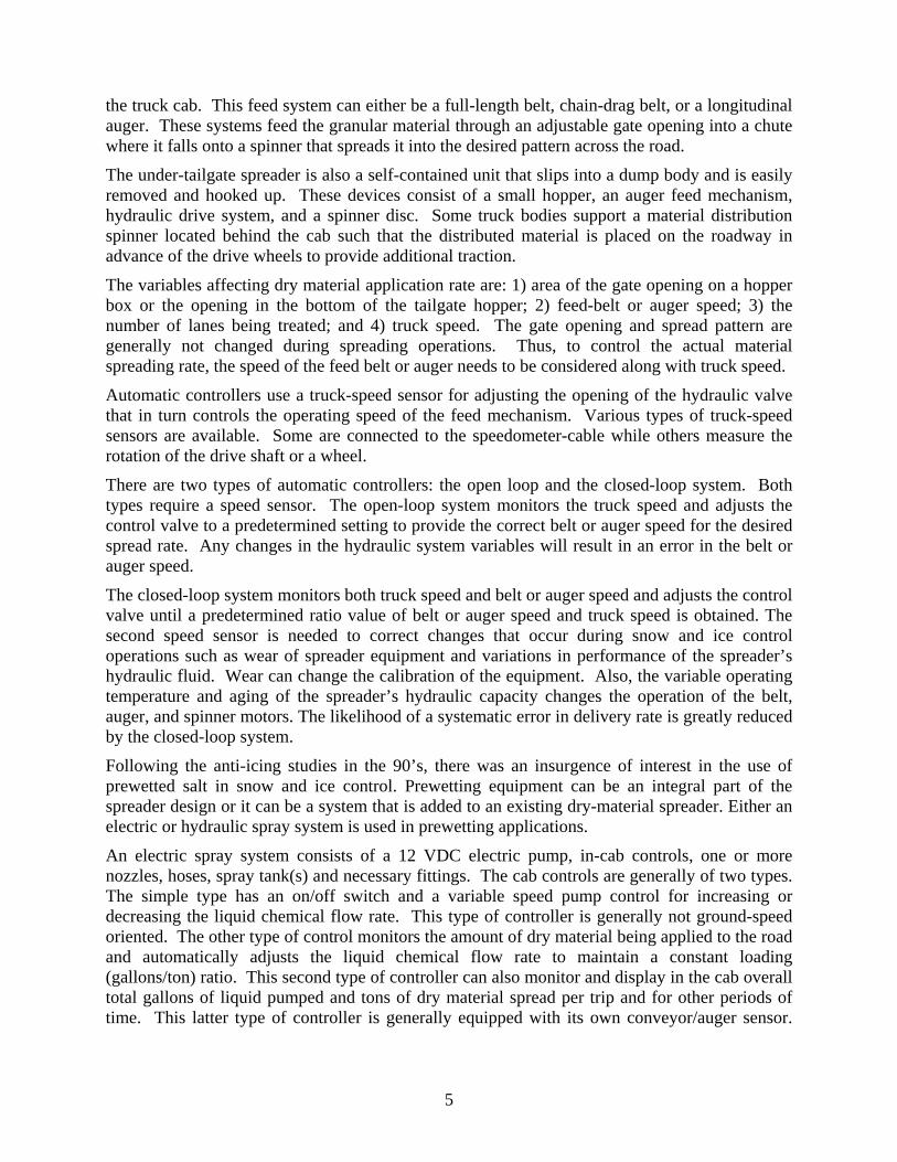
Figure 3-1 Example of having the truck jacked up to conduct drop tests in New York.
Also, these controllers usually can be used in conjunction with any type of ground-speed control system. Both types of liquid control systems operate independently of the spread width control.
A hydraulic spray system is usually in-line with the conveyor/auger motor so that the system provides a constant relationship between the amount of liquid and dry material being spread. The system includes a liquid spray pump, hydraulic motor, cab controls, nozzle kit, spray tanks and necessary hoses and fittings. A small hydraulic motor is used generally to drive the liquid chemical pump and is coupled in parallel with the conveyor/auger motor. An electrical solenoid valve is connected to an on/off system switch in the cab. An adjustable flow regulator is included to control the liquid chemical flow rate. Cab-mounted displays indicate the status of various system components. The systems available generally have multiple spray nozzles.
3. Background on Calibration Regardless of the type of spreader/controller used, it is extremely important to calibrate the system to ensure that the desired quantity of material (dry solid and liquids for prewetting systems) is actually being applied to the road. The most sophisticated controller is of little value if an unknown amount of material is being spread. All spreader equipment should be calibrated before winter operations begin. Even new spreader equipment delivered from the factory needs to be calibrated. Periodic calibrations should also be conducted because changes in mechanical linkages and components may occur and hydraulic systems perform differently as the season progresses. Any radical deviations in the spreader output compared to the control settings, such as running out of material before the route is completed or having excessive material remaining after an operation, should be investigated. Finally, it is a good practice to recalibrate the spreader equipment after any maintenance is performed on the spreader/truck system, including changing hydraulic fluid and related filters. Two methods are generally used to calibrate spreader equipment. One method involves connecting a speed simulator to the control panel so that the controller senses that the truck is traveling at a specified road speed. The second method involves jacking up the rear wheels so that the truck can be run in place at a specified speed. (See Figure 3-1 for an example.) In both methods, a timed volume, or weight, of discharged material is measured.
A less accurate third method for solid material involves operating the truck over a measured distance at a known constant speed and determining the weight of material spread by measuring the load weight before and after spreading or capturing and weighing the material dispensed over a known distance. The variation in operating parameters over a range of speeds makes it necessary to check the spreader calibration over a number of truck speeds.
A number of calibration procedures are available to the users of dry and prewetted solid material spreaders. These procedures are generally available from the spreader and controller manufactures. The Salt Institute provides a calibration procedure for dry solid material through its information data base (5).
7
The procedures for calibrating dry solid material spreaders are based generally on a catch or drop (discharge) and weigh basis. The amount of material discharged during calibration varies from manufacturer to manufacturer. The calibration procedures for prewetting liquid discharge are based on a volumetric test and are marginal, at best. The basic problem with some calibration procedures is that the user does not know if the calibration was performed satisfactorily, or at least, as best as could be expected. Some manufacturers have tried to circumvent this problem by recommending a calibration procedure that provides for “backing-into” or fine tuning the desired output by adjusting the controller discharge constant. The procedure given in this Guide for the calibration of spreader/controller combinations is based on using the controller manufacturer’s direction together with a calibration verification approach. This procedure augments the manufacturer’s recommendations with a check to verify that the calibration was performed correctly, or at least, as best as could be expected considering the limitations of the spreader/controller system.
Direction for obtaining the recommended calibration procedures from six controller manufacturers can be obtained by visiting their web sites. The addresses if these sites are given in Table 3-1
Table 3-1 Web Site Addresses for Six Controller Manufacturers Spreader/Controller Manufacturer URL Address
Cirus Controls http://www.ciruscontrols.com/manuals Component Technology http://www.certifiedpower.com/cpi_comp_storm.aspx Dickey-john http://www.dickey-john.com FORCE America * http://www.forceamerica.com/ Muncie Power Products * http://www.munciepower.com Pengwyn http://www.pengwyn.com/manuals.html
* Calibration protocols are not available from their web site. However, the procedures are available electronically upon request.
Additional information on the six controller manufacturers’ recommendations can be obtained form a recent Clear Roads study report (4). The user of this Guide should also contact the highway agency’s fleet manager or controller manufacturer if any questions remain on how to calibrate a specific system.
4. Equipment, Material, and Facilities Needed for Calibration and Calibration Verification Testing
The items needed for calibration are described first followed by those needed for calibration verification testing. 4.1 Equipment, Material, and Facilities Needed for Calibration The equipment, material, and facilities needed for the calibration of spreader/controller systems are varied and depend on the controller manufacturer’s requirements. However, some necessary, and provisional, items can be identified that cover most of the requirements. These items are divided into those needed for calibration of systems for distributing dry solid material and those needed for calibration of prewetting systems.
8
4.1.1 Calibration of Dry Solid Material Spreaders The items needed for this activity are:
• A known road distance near the maintenance yard where the spreader truck’s odometer and speedometer can be checked, if necessary.
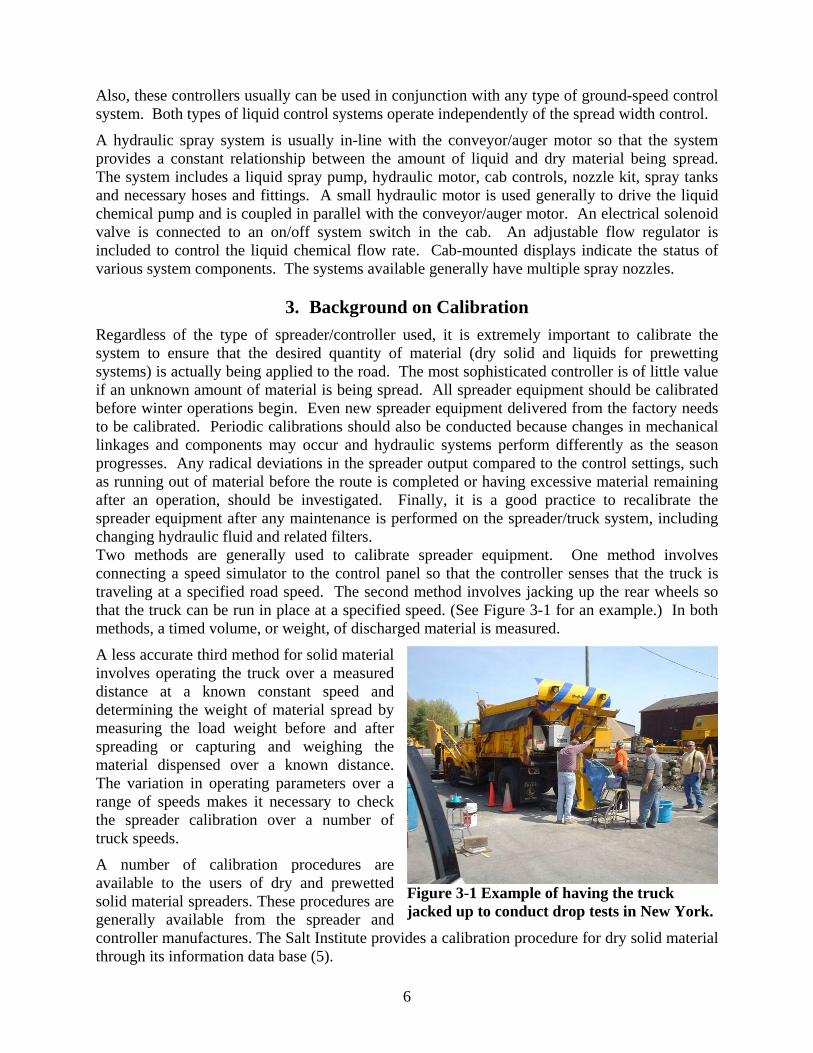
• A truck speed simulator; or a way to mechanically keep a constant vehicle speed during a discharge test, such as with a throttle, if equipped. A fan belt tensioner and a stick might work in the absence of a throttle. (Figure 4-1 shows a controller in a truck cab with the speed simulator set for 20 mph, and application rates set for 403 lbs/mile and 9.95 gallons/ton.)
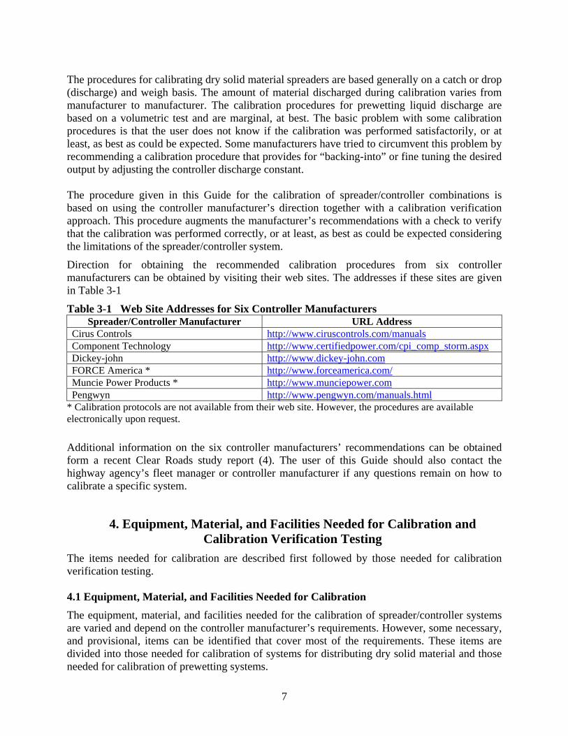
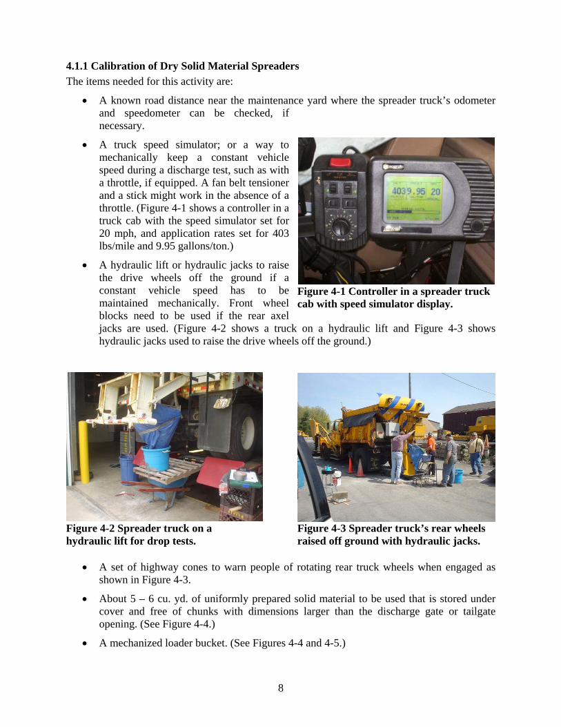
• A hydraulic lift or hydraulic jacks to raise the drive wheels off the ground if a constant vehicle speed has to be maintained mechanically. Front wheel blocks need to be used if the rear axel jacks are used. (Figure 4-2 shows a truck on a hydraulic lift and Figure 4-3 shows hydraulic jacks used to raise the drive wheels off the ground.)
Figure 4-2 Spreader truck on a Figure 4-3 Spreader truck’s rear wheels hydraulic lift for drop tests. raised off ground with hydraulic jacks.
• A set of highway cones to warn people of rotating rear truck wheels when engaged as shown in Figure 4-3.
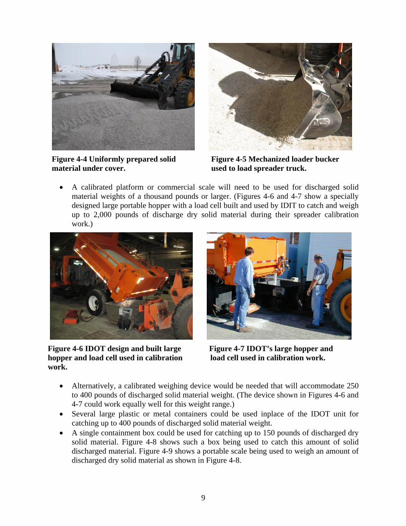
• About 5 – 6 cu. yd. of uniformly prepared solid material to be used that is stored under cover and free of chunks with dimensions larger than the discharge gate or tailgate opening. (See Figure 4-4.)
• A mechanized loader bucket. (See Figures 4-4 and 4-5.)
Figure 4-1 Controller in a spreader truckcab with speed simulator display.
9
Figure 4-4 Uniformly prepared solid Figure 4-5 Mechanized loader bucker material under cover. used to load spreader truck.
• A calibrated platform or commercial scale will need to be used for discharged solid material weights of a thousand pounds or larger. (Figures 4-6 and 4-7 show a specially designed large portable hopper with a load cell built and used by IDIT to catch and weigh up to 2,000 pounds of discharge dry solid material during their spreader calibration work.)
Figure 4-6 IDOT design and built large Figure 4-7 IDOT’s large hopper and hopper and load cell used in calibration load cell used in calibration work. work.
• Alternatively, a calibrated weighing device would be needed that will accommodate 250 to 400 pounds of discharged solid material weight. (The device shown in Figures 4-6 and 4-7 could work equally well for this weight range.)
• Several large plastic or metal containers could be used inplace of the IDOT unit for catching up to 400 pounds of discharged solid material weight.
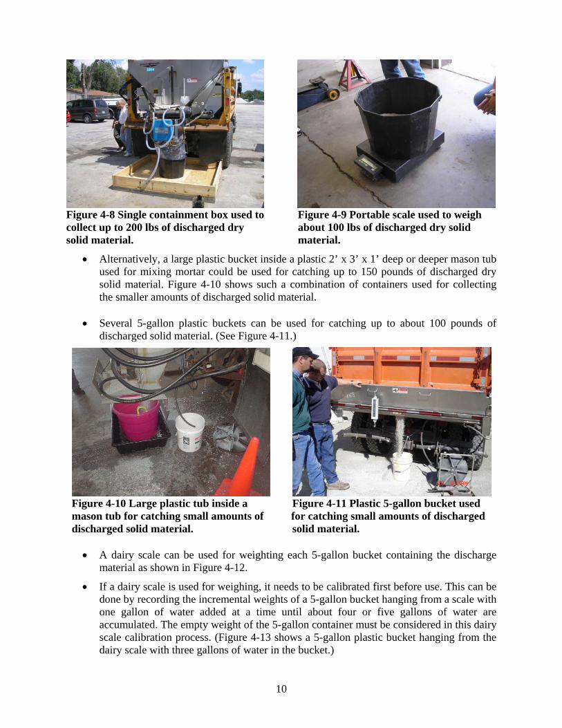
• A single containment box could be used for catching up to 150 pounds of discharged dry solid material. Figure 4-8 shows such a box being used to catch this amount of solid discharged material. Figure 4-9 shows a portable scale being used to weigh an amount of discharged dry solid material as shown in Figure 4-8.
10
Figure 4-8 Single containment box used to Figure 4-9 Portable scale used to weigh collect up to 200 lbs of discharged dry about 100 lbs of discharged dry solid solid material. material.
• Alternatively, a large plastic bucket inside a plastic 2’ x 3’ x 1’ deep or deeper mason tub used for mixing mortar could be used for catching up to 150 pounds of discharged dry solid material. Figure 4-10 shows such a combination of containers used for collecting the smaller amounts of discharged solid material.
• Several 5-gallon plastic buckets can be used for catching up to about 100 pounds of
discharged solid material. (See Figure 4-11.)
Figure 4-10 Large plastic tub inside a Figure 4-11 Plastic 5-gallon bucket used mason tub for catching small amounts of for catching small amounts of discharged discharged solid material. solid material.
• A dairy scale can be used for weighting each 5-gallon bucket containing the discharge material as shown in Figure 4-12.
• If a dairy scale is used for weighing, it needs to be calibrated first before use. This can be done by recording the incremental weights of a 5-gallon bucket hanging from a scale with one gallon of water added at a time until about four or five gallons of water are accumulated. The empty weight of the 5-gallon container must be considered in this dairy scale calibration process. (Figure 4-13 shows a 5-gallon plastic bucket hanging from the dairy scale with three gallons of water in the bucket.)

11
Figure 4-12 Dairy scale used to weigh a Figure 4-13 A 5-gallon bucket containing 5-gollon plastic bucket with solid discharged three gallons of water suspended from material. a dairy scale.
• The larger discharged weights can be dumped directly onto the solid storage pile without handling. (See Figure 4-14.)
• The smaller discharge weights can be dumped into the bucket of a high loader for transfer to the solid storage pile.
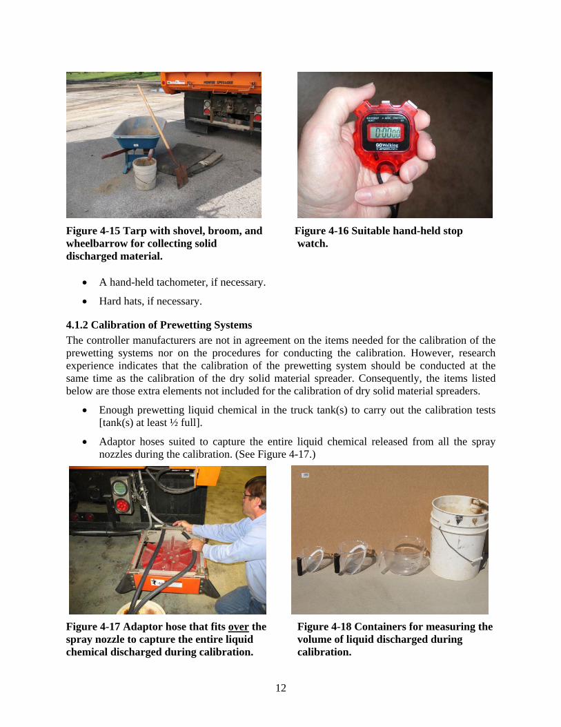
• A small tarp is needed to help retain the smaller amounts of discharged solid material. (See Figure 4-15)
• Shovels, brooms, wheelbarrows, etc. are also needed to help in collecting the smaller discharged of weight of solid material. (See Figure 4-15.)
• A stop watch, if necessary.(See Figure 4-16)
Figure 4-14 Large discharged weights of dry solid material dumped directly on to the solid storage pile.
12
Figure 4-15 Tarp with shovel, broom, and Figure 4-16 Suitable hand-held stop wheelbarrow for collecting solid watch. discharged material.
• A hand-held tachometer, if necessary.
• Hard hats, if necessary.
4.1.2 Calibration of Prewetting Systems The controller manufacturers are not in agreement on the items needed for the calibration of the prewetting systems nor on the procedures for conducting the calibration. However, research experience indicates that the calibration of the prewetting system should be conducted at the same time as the calibration of the dry solid material spreader. Consequently, the items listed below are those extra elements not included for the calibration of dry solid material spreaders.
• Enough prewetting liquid chemical in the truck tank(s) to carry out the calibration tests [tank(s) at least ½ full].
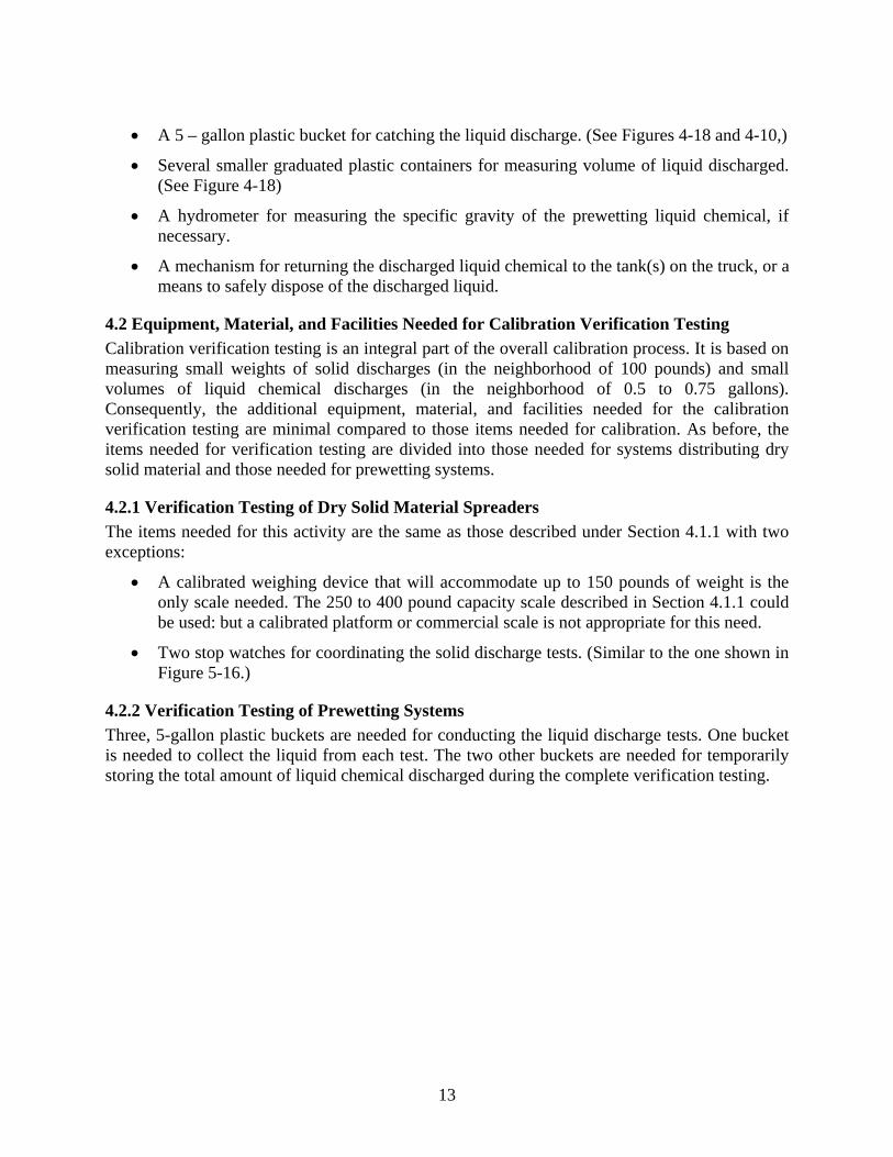
• Adaptor hoses suited to capture the entire liquid chemical released from all the spray nozzles during the calibration. (See Figure 4-17.)
Figure 4-17 Adaptor hose that fits over the Figure 4-18 Containers for measuring the spray nozzle to capture the entire liquid volume of liquid discharged during chemical discharged during calibration. calibration.
13
• A 5 – gallon plastic bucket for catching the liquid discharge. (See Figures 4-18 and 4-10,)
• Several smaller graduated plastic containers for measuring volume of liquid discharged. (See Figure 4-18)
• A hydrometer for measuring the specific gravity of the prewetting liquid chemical, if necessary.
• A mechanism for returning the discharged liquid chemical to the tank(s) on the truck, or a means to safely dispose of the discharged liquid.
4.2 Equipment, Material, and Facilities Needed for Calibration Verification Testing Calibration verification testing is an integral part of the overall calibration process. It is based on measuring small weights of solid discharges (in the neighborhood of 100 pounds) and small volumes of liquid chemical discharges (in the neighborhood of 0.5 to 0.75 gallons). Consequently, the additional equipment, material, and facilities needed for the calibration verification testing are minimal compared to those items needed for calibration. As before, the items needed for verification testing are divided into those needed for systems distributing dry solid material and those needed for prewetting systems.
4.2.1 Verification Testing of Dry Solid Material Spreaders The items needed for this activity are the same as those described under Section 4.1.1 with two exceptions:
• A calibrated weighing device that will accommodate up to 150 pounds of weight is the only scale needed. The 250 to 400 pound capacity scale described in Section 4.1.1 could be used: but a calibrated platform or commercial scale is not appropriate for this need.
• Two stop watches for coordinating the solid discharge tests. (Similar to the one shown in Figure 5-16.)
4.2.2 Verification Testing of Prewetting Systems Three, 5-gallon plastic buckets are needed for conducting the liquid discharge tests. One bucket is needed to collect the liquid from each test. The two other buckets are needed for temporarily storing the total amount of liquid chemical discharged during the complete verification testing.
14
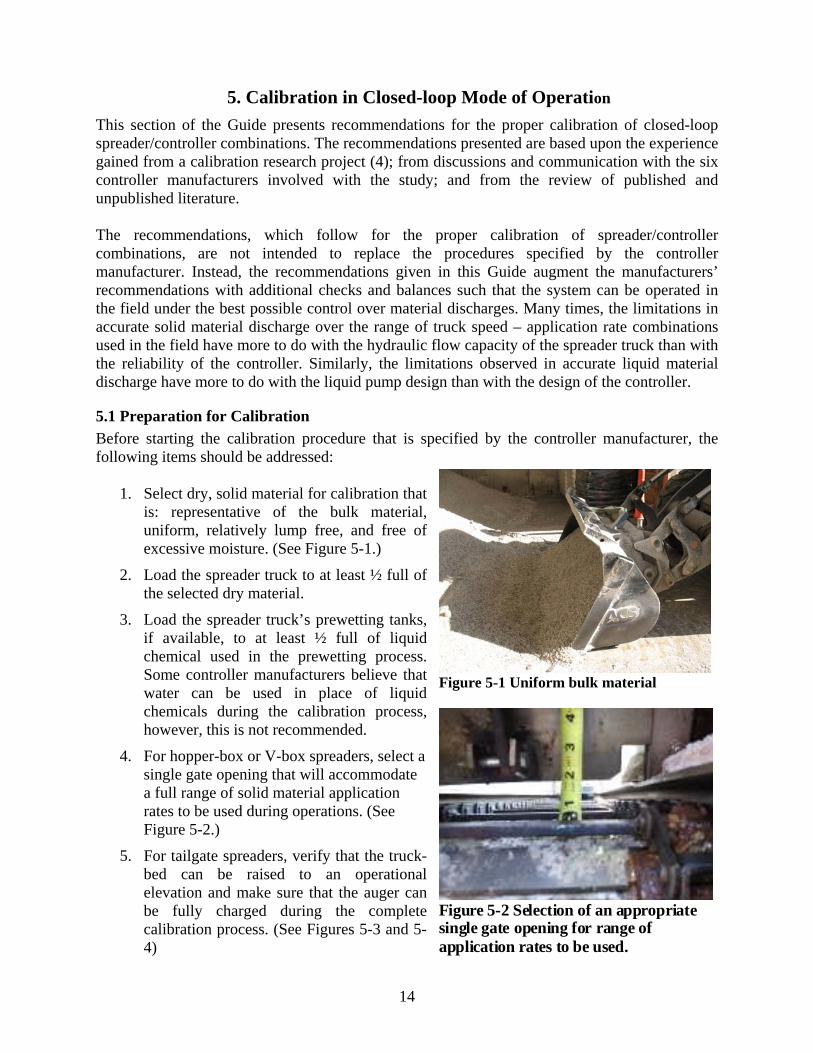
Figure 5-2 Selection of an appropriate single gate opening for range of application rates to be used.
Figure 5-1 Uniform bulk material
5. Calibration in Closed-loop Mode of Operation
This section of the Guide presents recommendations for the proper calibration of closed-loop spreader/controller combinations. The recommendations presented are based upon the experience gained from a calibration research project (4); from discussions and communication with the six controller manufacturers involved with the study; and from the review of published and unpublished literature. The recommendations, which follow for the proper calibration of spreader/controller combinations, are not intended to replace the procedures specified by the controller manufacturer. Instead, the recommendations given in this Guide augment the manufacturers’ recommendations with additional checks and balances such that the system can be operated in the field under the best possible control over material discharges. Many times, the limitations in accurate solid material discharge over the range of truck speed – application rate combinations used in the field have more to do with the hydraulic flow capacity of the spreader truck than with the reliability of the controller. Similarly, the limitations observed in accurate liquid material discharge have more to do with the liquid pump design than with the design of the controller.
5.1 Preparation for Calibration Before starting the calibration procedure that is specified by the controller manufacturer, the following items should be addressed:
1. Select dry, solid material for calibration that
is: representative of the bulk material, uniform, relatively lump free, and free of excessive moisture. (See Figure 5-1.)
2. Load the spreader truck to at least ½ full of the selected dry material.
3. Load the spreader truck’s prewetting tanks, if available, to at least ½ full of liquid chemical used in the prewetting process. Some controller manufacturers believe that water can be used in place of liquid chemicals during the calibration process, however, this is not recommended.
4. For hopper-box or V-box spreaders, select a single gate opening that will accommodate a full range of solid material application rates to be used during operations. (See Figure 5-2.)
5. For tailgate spreaders, verify that the truck-bed can be raised to an operational elevation and make sure that the auger can be fully charged during the complete calibration process. (See Figures 5-3 and 5-4)

15
Figure 5-3 Truck-bed raised to an Figure 5-4 Photo showing tailgate auger operational elevation for calibration. fully charged during the calibration process.
6. When calibrating the prewetting system, leave the spray nozzles in the discharge lines to account for back-pressure conditions. (See Figure 5-5.)
(A) (B) Figure 5-5 Collection hoses placed over spray nozzles in the prewetting discharge lines.
7. Assemble the equipment identified in Section 4.1 that is needed for calibration.
8. Verify that the scales used to weigh the solid discharge material and the containers used to measure the liquid discharge amount have been properly calibrated.
9. Verify that the truck’s speedometer has been properly calibrated and the speedometer display agrees with the speed readout on the controller. (See Figure 5-6.)
10. Fill the truck’s hydraulic oil reservoirs to recommended capacity.
11. Verify that the truck’s hydraulic oil can be warmed to normal operational temperature and that the temperature level can be held constant for the time required for calibration. (See Figure 5-7)
16
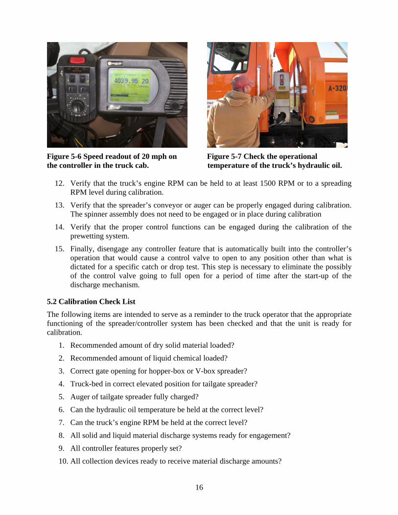
Figure 5-6 Speed readout of 20 mph on Figure 5-7 Check the operational the controller in the truck cab. temperature of the truck’s hydraulic oil.
12. Verify that the truck’s engine RPM can be held to at least 1500 RPM or to a spreading RPM level during calibration.
13. Verify that the spreader’s conveyor or auger can be properly engaged during calibration. The spinner assembly does not need to be engaged or in place during calibration
14. Verify that the proper control functions can be engaged during the calibration of the prewetting system.
15. Finally, disengage any controller feature that is automatically built into the controller’s operation that would cause a control valve to open to any position other than what is dictated for a specific catch or drop test. This step is necessary to eliminate the possibly of the control valve going to full open for a period of time after the start-up of the discharge mechanism.
5.2 Calibration Check List The following items are intended to serve as a reminder to the truck operator that the appropriate functioning of the spreader/controller system has been checked and that the unit is ready for calibration.
1. Recommended amount of dry solid material loaded?
2. Recommended amount of liquid chemical loaded?
3. Correct gate opening for hopper-box or V-box spreader?
4. Truck-bed in correct elevated position for tailgate spreader?
5. Auger of tailgate spreader fully charged?
6. Can the hydraulic oil temperature be held at the correct level?
7. Can the truck’s engine RPM be held at the correct level?
8. All solid and liquid material discharge systems ready for engagement?
9. All controller features properly set?
10. All collection devices ready to receive material discharge amounts?
17
5.3 Calibration According to Manufacturer’s Specifications Each controller manufacturer provides the user with a set of specific instructions for the calibration of spreader/controller combinations. Directions for obtaining calibration procedures for six controller manufacturers can be found from their Web sites given in Table 3-1. Although each manufacturer has specific procedures, certain fundamental generic steps of the calibration process can be identified and are given below. The following steps are to be taken after executing the calibration check list described in Section 5.2.
1. Remove the spinner assembly from the truck but keep the hydraulic hoses connected.
2. Warm the truck’s hydraulic oil to the specified operational temperature.
3. Discharge a small amount of solid and liquid chemical to make sure that the spreader’s distribution mechanism is fully charged. Discard these amounts.
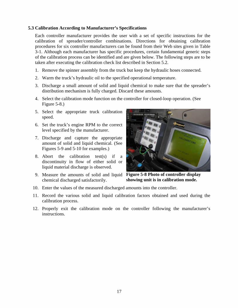
4. Select the calibration mode function on the controller for closed-loop operation. (See Figure 5-8.)
5. Select the appropriate truck calibration speed.
6. Set the truck’s engine RPM to the correct level specified by the manufacturer.
7. Discharge and capture the appropriate amount of solid and liquid chemical. (See Figures 5-9 and 5-10 for examples.)
8. Abort the calibration test(s) if a discontinuity in flow of either solid or liquid material discharge is observed.
9. Measure the amounts of solid and liquid chemical discharged satisfactorily.
10. Enter the values of the measured discharged amounts into the controller.
11. Record the various solid and liquid calibration factors obtained and used during the calibration process.
12. Properly exit the calibration mode on the controller following the manufacturer’s instructions.
Figure 5-8 Photo of controller display showing unit is in calibration mode.
18
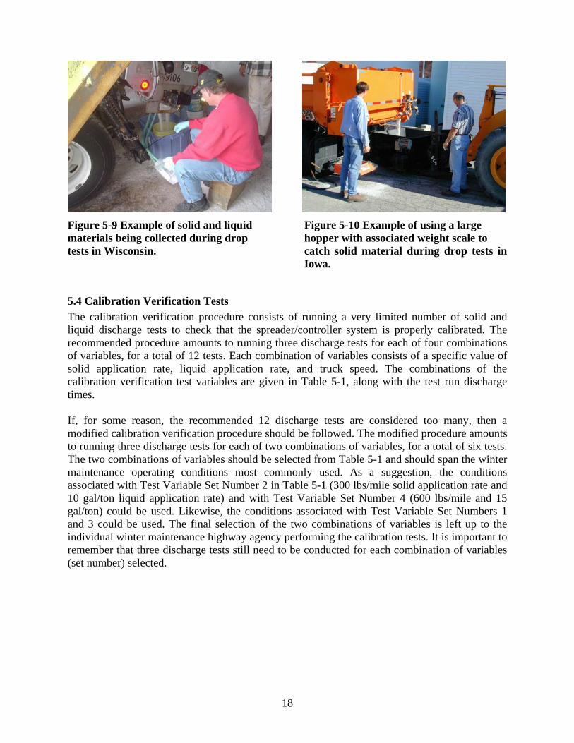
Figure 5-9 Example of solid and liquid Figure 5-10 Example of using a large materials being collected during drop hopper with associated weight scale to tests in Wisconsin. catch solid material during drop tests in
Iowa.
5.4 Calibration Verification Tests The calibration verification procedure consists of running a very limited number of solid and liquid discharge tests to check that the spreader/controller system is properly calibrated. The recommended procedure amounts to running three discharge tests for each of four combinations of variables, for a total of 12 tests. Each combination of variables consists of a specific value of solid application rate, liquid application rate, and truck speed. The combinations of the calibration verification test variables are given in Table 5-1, along with the test run discharge times. If, for some reason, the recommended 12 discharge tests are considered too many, then a modified calibration verification procedure should be followed. The modified procedure amounts to running three discharge tests for each of two combinations of variables, for a total of six tests. The two combinations of variables should be selected from Table 5-1 and should span the winter maintenance operating conditions most commonly used. As a suggestion, the conditions associated with Test Variable Set Number 2 in Table 5-1 (300 lbs/mile solid application rate and 10 gal/ton liquid application rate) and with Test Variable Set Number 4 (600 lbs/mile and 15 gal/ton) could be used. Likewise, the conditions associated with Test Variable Set Numbers 1 and 3 could be used. The final selection of the two combinations of variables is left up to the individual winter maintenance highway agency performing the calibration tests. It is important to remember that three discharge tests still need to be conducted for each combination of variables (set number) selected.
19
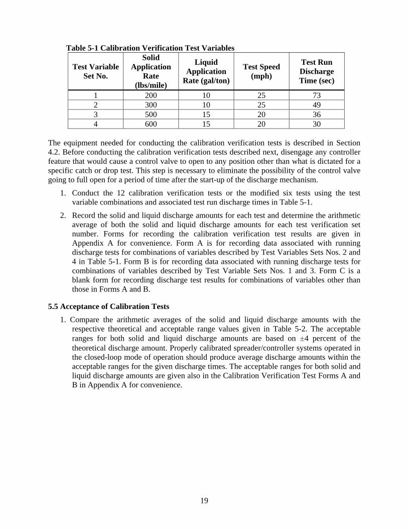
Table 5-1 Calibration Verification Test Variables
Test Variable Set No.
Solid Application
Rate (lbs/mile)
Liquid Application
Rate (gal/ton)
Test Speed (mph)
Test Run Discharge Time (sec)
1 200 10 25 73 2 300 10 25 49 3 500 15 20 36 4 600 15 20 30
The equipment needed for conducting the calibration verification tests is described in Section 4.2. Before conducting the calibration verification tests described next, disengage any controller feature that would cause a control valve to open to any position other than what is dictated for a specific catch or drop test. This step is necessary to eliminate the possibility of the control valve going to full open for a period of time after the start-up of the discharge mechanism.
1. Conduct the 12 calibration verification tests or the modified six tests using the test variable combinations and associated test run discharge times in Table 5-1.
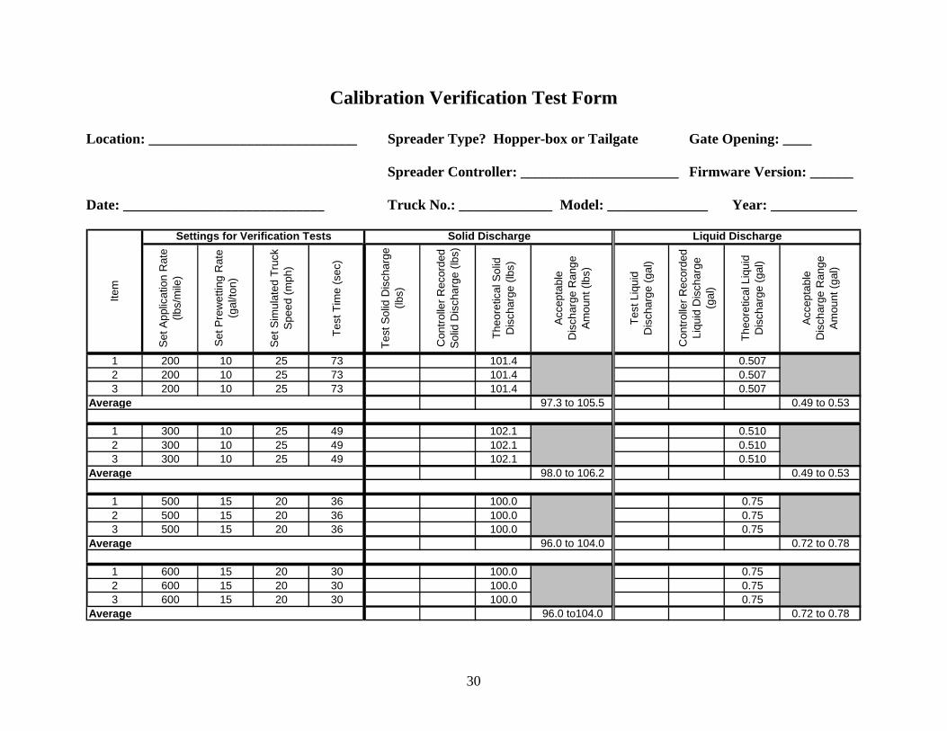
2. Record the solid and liquid discharge amounts for each test and determine the arithmetic average of both the solid and liquid discharge amounts for each test verification set number. Forms for recording the calibration verification test results are given in Appendix A for convenience. Form A is for recording data associated with running discharge tests for combinations of variables described by Test Variables Sets Nos. 2 and 4 in Table 5-1. Form B is for recording data associated with running discharge tests for combinations of variables described by Test Variable Sets Nos. 1 and 3. Form C is a blank form for recording discharge test results for combinations of variables other than those in Forms A and B.
5.5 Acceptance of Calibration Tests 1. Compare the arithmetic averages of the solid and liquid discharge amounts with the
respective theoretical and acceptable range values given in Table 5-2. The acceptable ranges for both solid and liquid discharge amounts are based on ±4 percent of the theoretical discharge amount. Properly calibrated spreader/controller systems operated in the closed-loop mode of operation should produce average discharge amounts within the acceptable ranges for the given discharge times. The acceptable ranges for both solid and liquid discharge amounts are given also in the Calibration Verification Test Forms A and B in Appendix A for convenience.
20
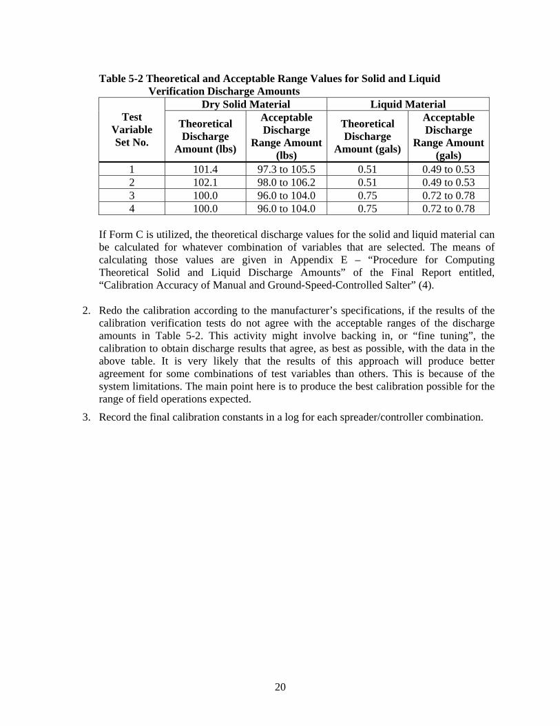
Table 5-2 Theoretical and Acceptable Range Values for Solid and Liquid
Verification Discharge Amounts Dry Solid Material Liquid Material
Test Variable Set No.
Theoretical Discharge
Amount (lbs)
Acceptable Discharge
Range Amount (lbs)
Theoretical Discharge
Amount (gals)
Acceptable Discharge
Range Amount (gals)
1 101.4 97.3 to 105.5 0.51 0.49 to 0.53 2 102.1 98.0 to 106.2 0.51 0.49 to 0.53 3 100.0 96.0 to 104.0 0.75 0.72 to 0.78 4 100.0 96.0 to 104.0 0.75 0.72 to 0.78
If Form C is utilized, the theoretical discharge values for the solid and liquid material can be calculated for whatever combination of variables that are selected. The means of calculating those values are given in Appendix E – “Procedure for Computing Theoretical Solid and Liquid Discharge Amounts” of the Final Report entitled, “Calibration Accuracy of Manual and Ground-Speed-Controlled Salter” (4).
2. Redo the calibration according to the manufacturer’s specifications, if the results of the calibration verification tests do not agree with the acceptable ranges of the discharge amounts in Table 5-2. This activity might involve backing in, or “fine tuning”, the calibration to obtain discharge results that agree, as best as possible, with the data in the above table. It is very likely that the results of this approach will produce better agreement for some combinations of test variables than others. This is because of the system limitations. The main point here is to produce the best calibration possible for the range of field operations expected.
3. Record the final calibration constants in a log for each spreader/controller combination.
21
6. Calibration in Open-loop Mode of Operation This section of the Guide presents recommendations for the proper calibration of open-loop spreader/controller combinations. The recommendations presented are based upon the experience gained from a calibration research project (5); from discussions and communication with the six controller manufacturers involved with the study; and from the review of published and unpublished literature. The recommendations, which follow for the proper calibration of spreader/controller combinations, are not intended to replace the procedures specified by the controller manufacturer. Instead, the recommendations given in this Guide augment the manufacturers’ recommendations with additional checks and balances such that the system can be operated in the field under the best possible control over material discharges. Many times, the limitations in accurate solid material discharge over the range of truck speed – application rate combinations used in the field have more to do with the hydraulic flow capacity of the spreader truck than with the reliability of the controller. Similarly, the limitations observed in accurate liquid material discharge have more to do with the liquid pump design than with the design of the controller.
6.1 Preparation for Calibration Before starting the calibration procedure that is specified by the controller manufacturer, the following items should be addressed:
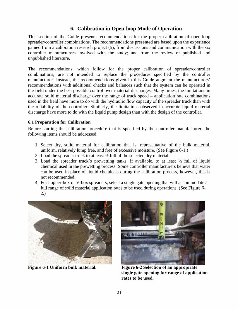
1. Select dry, solid material for calibration that is: representative of the bulk material, uniform, relatively lump free, and free of excessive moisture. (See Figure 6-1.)
2. Load the spreader truck to at least ½ full of the selected dry material. 3. Load the spreader truck’s prewetting tanks, if available, to at least ½ full of liquid
chemical used in the prewetting process. Some controller manufacturers believe that water can be used in place of liquid chemicals during the calibration process, however, this is not recommended.
4. For hopper-box or V-box spreaders, select a single gate opening that will accommodate a full range of solid material application rates to be used during operations. (See Figure 6-2.)
Figure 6-1 Uniform bulk material. Figure 6-2 Selection of an appropriate single gate opening for range of application rates to be used.

22
5. For tailgate spreaders, verify that the truck-bed can be raised to an operational elevation and make sure that the auger can be fully charged during the complete calibration process. (See Figures 6-3 and 6-4)
Figure 6-3 Truck-bed raised to an Figure 6-4 Photo showing tailgate auger operational elevation for calibration. fully charged during the calibration process.
6. When calibrating the prewetting system, leave the spray nozzles in the discharge lines to account for back-pressure conditions. (See Figure 6-5.)
(A) (B) Figure 6-5 Collection hoses placed over spray nozzles in the prewetting discharge lines.
7. Assemble the equipment identified in Section 4.1 that is needed for calibration.
8. Verify that the scales used to weigh the solid discharge material and the containers used to measure the liquid discharge amount have been properly calibrated.
9. Verify that the truck’s speedometer has been properly calibrated and the speedometer display agrees with the speed readout on the controller. (See Figure 6-6.)
10. Fill the truck’s hydraulic oil reservoirs to recommended capacity.
23
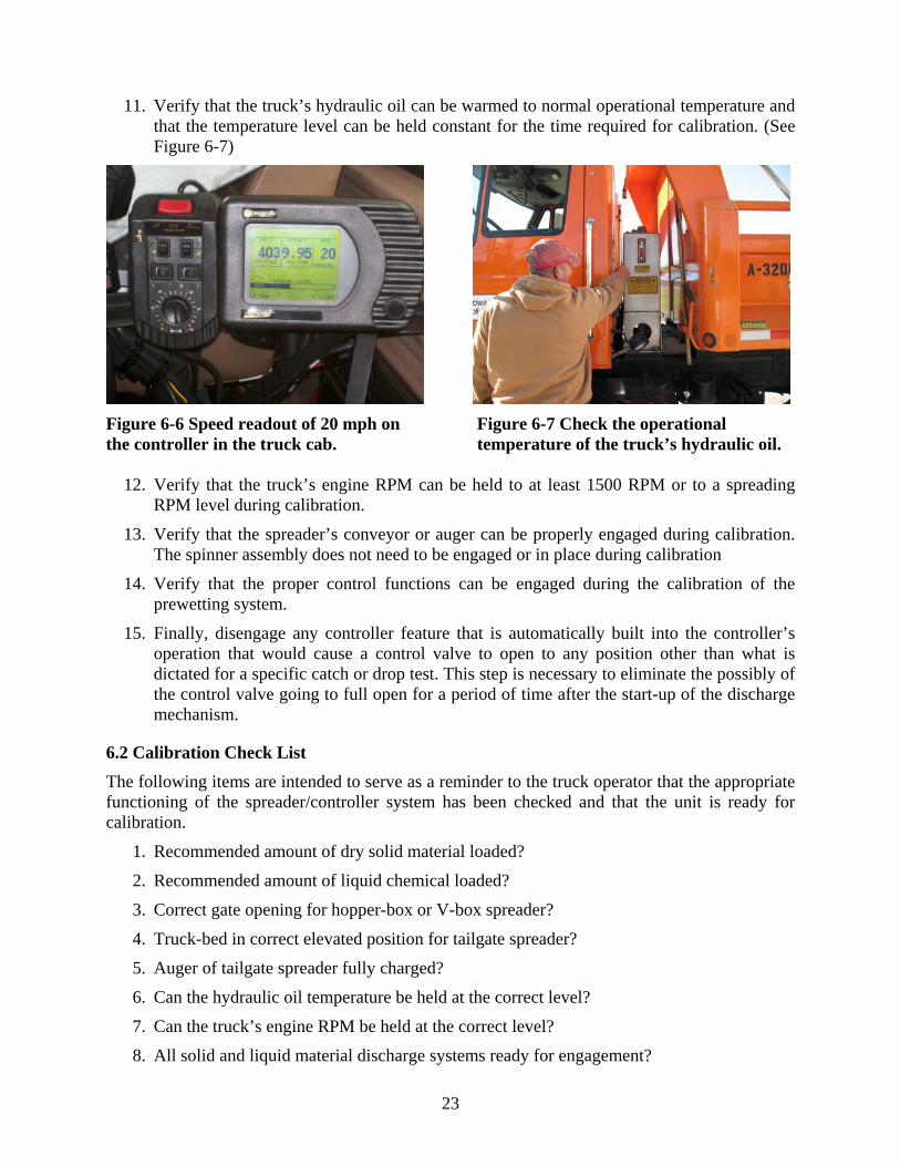
11. Verify that the truck’s hydraulic oil can be warmed to normal operational temperature and that the temperature level can be held constant for the time required for calibration. (See Figure 6-7)
Figure 6-6 Speed readout of 20 mph on Figure 6-7 Check the operational the controller in the truck cab. temperature of the truck’s hydraulic oil.
12. Verify that the truck’s engine RPM can be held to at least 1500 RPM or to a spreading RPM level during calibration.
13. Verify that the spreader’s conveyor or auger can be properly engaged during calibration. The spinner assembly does not need to be engaged or in place during calibration
14. Verify that the proper control functions can be engaged during the calibration of the prewetting system.
15. Finally, disengage any controller feature that is automatically built into the controller’s operation that would cause a control valve to open to any position other than what is dictated for a specific catch or drop test. This step is necessary to eliminate the possibly of the control valve going to full open for a period of time after the start-up of the discharge mechanism.
6.2 Calibration Check List The following items are intended to serve as a reminder to the truck operator that the appropriate functioning of the spreader/controller system has been checked and that the unit is ready for calibration.
1. Recommended amount of dry solid material loaded?
2. Recommended amount of liquid chemical loaded?
3. Correct gate opening for hopper-box or V-box spreader?
4. Truck-bed in correct elevated position for tailgate spreader?
5. Auger of tailgate spreader fully charged?
6. Can the hydraulic oil temperature be held at the correct level?
7. Can the truck’s engine RPM be held at the correct level?
8. All solid and liquid material discharge systems ready for engagement?
24
9. All controller features properly set?
10. All collection devices ready to receive material discharge amounts?
6.3 Calibration According to Manufacturer’s Specifications Each controller manufacturer provides the user with a set of specific instructions for the calibration of spreader/controller combinations. Directions for obtaining calibration procedures for a number of controller manufacturers can be found from their Web sites given in Table 3-1. Although each manufacturer has specific procedures, certain fundamental generic steps of the calibration process can be identified and are given below. The following steps are to be taken after executing the calibration check list described in Section 6.2.
1. Remove the spinner assembly from the truck, but keep the hydraulic hoses connected.
2. If a speed simulator is not available, block the front wheels and elevate the rear wheels off the ground.
3. Warm the truck’s hydraulic oil to the specified operational temperature.
4. Discharge a small amount of solid and liquid chemical to make sure that the spreader’s distribution mechanism is fully charged. Discard these amounts.
5. Select the calibration mode function on the controller for open-loop operation.
6. Select the appropriate truck calibration speed.
7. Set the truck’s engine RPM to the correct level specified by the manufacturer.
8. Select the solid discharge setting and the prewetting rate (if available) on the controller according to the manufacturer’s specifications.
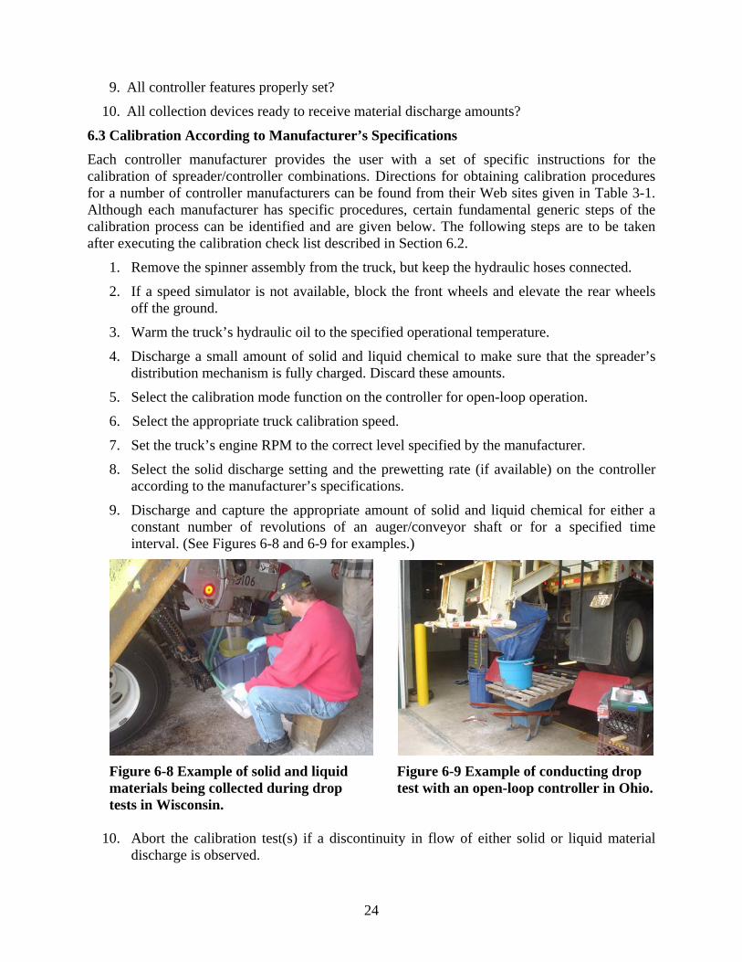
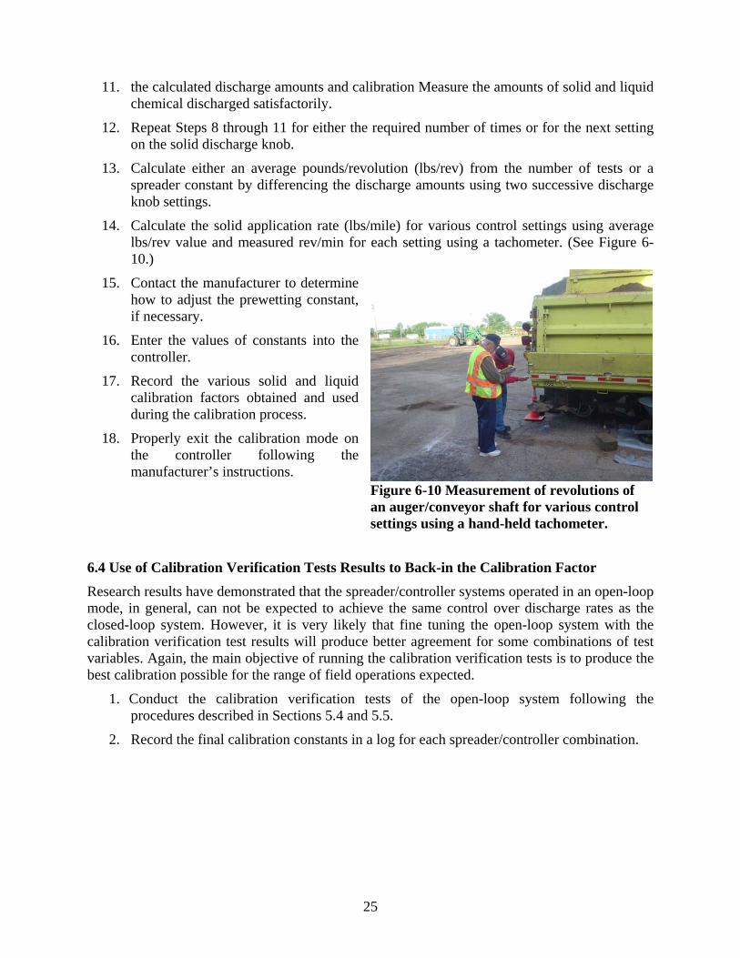
9. Discharge and capture the appropriate amount of solid and liquid chemical for either a constant number of revolutions of an auger/conveyor shaft or for a specified time interval. (See Figures 6-8 and 6-9 for examples.)
Figure 6-8 Example of solid and liquid Figure 6-9 Example of conducting drop materials being collected during drop test with an open-loop controller in Ohio. tests in Wisconsin.
10. Abort the calibration test(s) if a discontinuity in flow of either solid or liquid material discharge is observed.
25
11. the calculated discharge amounts and calibration Measure the amounts of solid and liquid chemical discharged satisfactorily.
12. Repeat Steps 8 through 11 for either the required number of times or for the next setting on the solid discharge knob.
13. Calculate either an average pounds/revolution (lbs/rev) from the number of tests or a spreader constant by differencing the discharge amounts using two successive discharge knob settings.
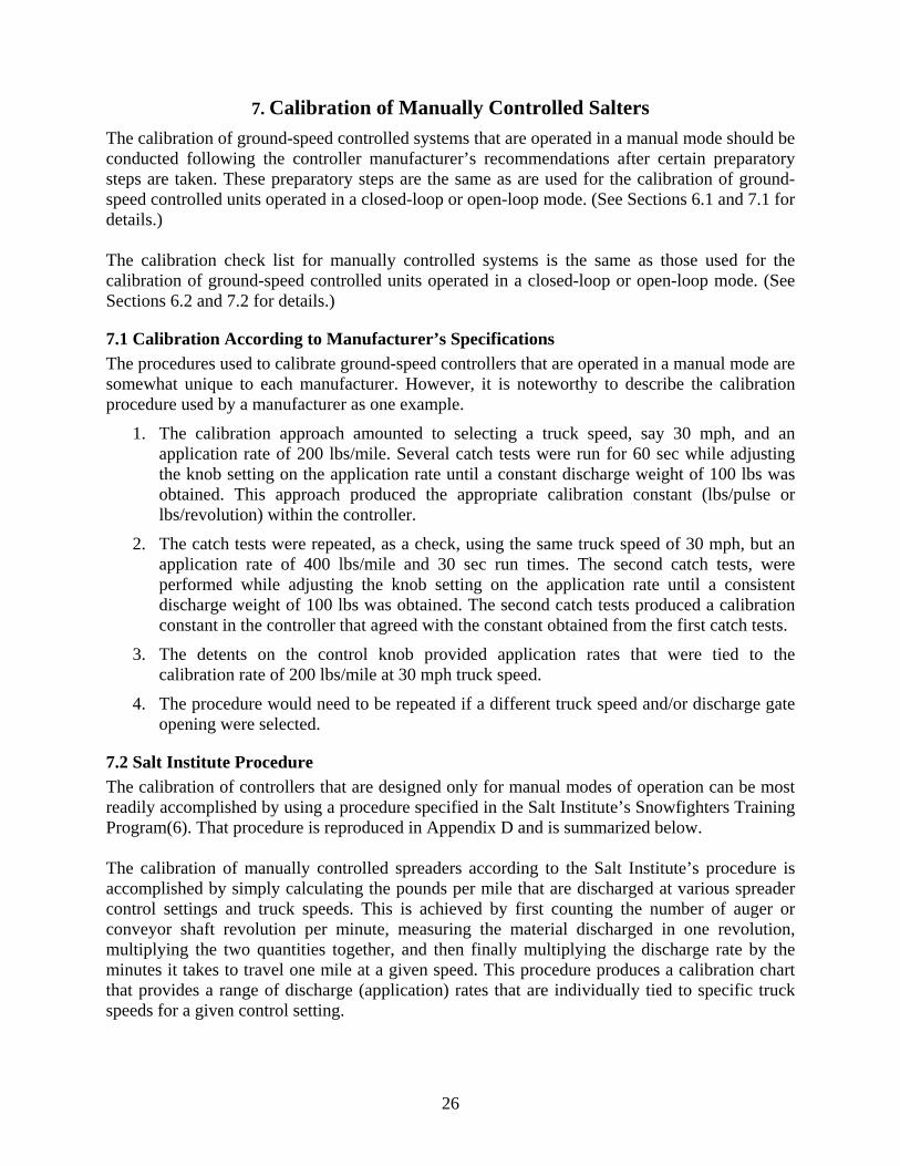
14. Calculate the solid application rate (lbs/mile) for various control settings using average lbs/rev value and measured rev/min for each setting using a tachometer. (See Figure 6-10.)
15. Contact the manufacturer to determine how to adjust the prewetting constant, if necessary.
16. Enter the values of constants into the controller.
17. Record the various solid and liquid calibration factors obtained and used during the calibration process.
18. Properly exit the calibration mode on the controller following the manufacturer’s instructions.
6.4 Use of Calibration Verification Tests Results to Back-in the Calibration Factor Research results have demonstrated that the spreader/controller systems operated in an open-loop mode, in general, can not be expected to achieve the same control over discharge rates as the closed-loop system. However, it is very likely that fine tuning the open-loop system with the calibration verification test results will produce better agreement for some combinations of test variables. Again, the main objective of running the calibration verification tests is to produce the best calibration possible for the range of field operations expected.
1. Conduct the calibration verification tests of the open-loop system following the procedures described in Sections 5.4 and 5.5.
2. Record the final calibration constants in a log for each spreader/controller combination.
Figure 6-10 Measurement of revolutions of an auger/conveyor shaft for various control settings using a hand-held tachometer.
26
7. Calibration of Manually Controlled Salters The calibration of ground-speed controlled systems that are operated in a manual mode should be conducted following the controller manufacturer’s recommendations after certain preparatory steps are taken. These preparatory steps are the same as are used for the calibration of ground-speed controlled units operated in a closed-loop or open-loop mode. (See Sections 6.1 and 7.1 for details.) The calibration check list for manually controlled systems is the same as those used for the calibration of ground-speed controlled units operated in a closed-loop or open-loop mode. (See Sections 6.2 and 7.2 for details.)
7.1 Calibration According to Manufacturer’s Specifications The procedures used to calibrate ground-speed controllers that are operated in a manual mode are somewhat unique to each manufacturer. However, it is noteworthy to describe the calibration procedure used by a manufacturer as one example.
1. The calibration approach amounted to selecting a truck speed, say 30 mph, and an application rate of 200 lbs/mile. Several catch tests were run for 60 sec while adjusting the knob setting on the application rate until a constant discharge weight of 100 lbs was obtained. This approach produced the appropriate calibration constant (lbs/pulse or lbs/revolution) within the controller.
2. The catch tests were repeated, as a check, using the same truck speed of 30 mph, but an application rate of 400 lbs/mile and 30 sec run times. The second catch tests, were performed while adjusting the knob setting on the application rate until a consistent discharge weight of 100 lbs was obtained. The second catch tests produced a calibration constant in the controller that agreed with the constant obtained from the first catch tests.
3. The detents on the control knob provided application rates that were tied to the calibration rate of 200 lbs/mile at 30 mph truck speed.
4. The procedure would need to be repeated if a different truck speed and/or discharge gate opening were selected.
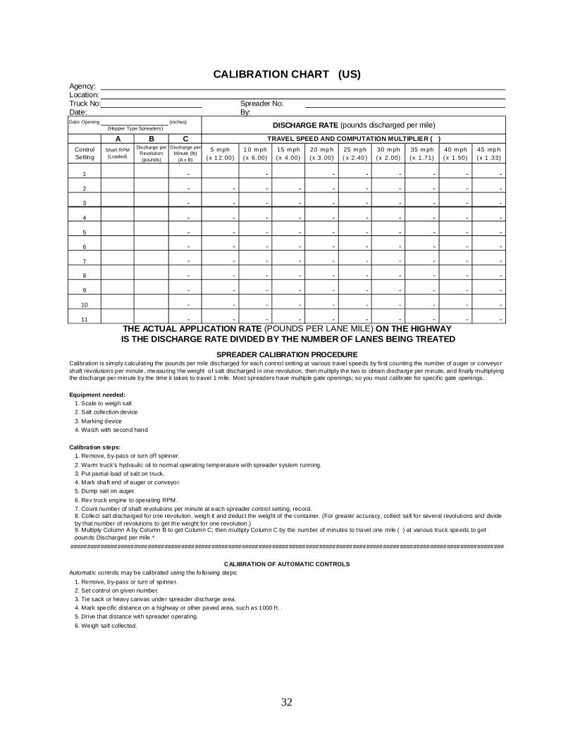
7.2 Salt Institute Procedure The calibration of controllers that are designed only for manual modes of operation can be most readily accomplished by using a procedure specified in the Salt Institute’s Snowfighters Training Program(6). That procedure is reproduced in Appendix D and is summarized below. The calibration of manually controlled spreaders according to the Salt Institute’s procedure is accomplished by simply calculating the pounds per mile that are discharged at various spreader control settings and truck speeds. This is achieved by first counting the number of auger or conveyor shaft revolution per minute, measuring the material discharged in one revolution, multiplying the two quantities together, and then finally multiplying the discharge rate by the minutes it takes to travel one mile at a given speed. This procedure produces a calibration chart that provides a range of discharge (application) rates that are individually tied to specific truck speeds for a given control setting.
27
Checks of several discharge rates/control settings should be performed to verify that the calibration of the manually controlled system was performed correctly. For hopper-box spreaders, the system needs to be calibrated for specific gate openings. For tailgate spreaders, the truck-bed needs to be raised to an operational elevation and the auger needs to be fully charged throughout the complete calibration process. Finally, the calibration chart(s) for each spreader/controller combination operated in a manual mode needs to be recorded in a log and displayed in the truck cab for the operator’s use.
8. Recommended Timing and Frequency of Calibration It is extremely important to maintain spreader/controller systems in good working order and to ensure that the units are calibrated to the best possible extent. A well maintained and calibrated spreader/controller system will return benefits to the highway agency in terms of material and manpower cost savings. The recommended timing and frequency of the system calibration are addressed in varying degrees by the controller manufacturers. The recommendations given below, attempt to unify the approach towards proper calibration. This approach is based on research experience and discussions with field winter maintenance personnel and representatives of controller manufacturers. Spreader/controller systems should be calibrated/recalibrated under the following conditions:
• When the spreader/controller unit is first put into service.
• Annually, before snow and ice control operations begin.
• After major maintenance of the spreader truck is performed and after truck hydraulic fluid and filters are replaced.
• After the controller unit is repaired or when the speed (truck or belt/auger) sensors are replaced.
• After new snow and ice control material is delivered to the maintenance garage location.
9. Calibration Record Keeping The maintaining of the calibration history of individual spreader/controller combinations is just as important as the timing and frequency of the calibration of these units. It is through this consistent record keeping that light is shed on potential problems, not only with the controller and related sensors, but also with the spreader truck on which the controller is installed. Procedures should be established for maintaining calibration records at the maintenance garage level for each spreader/controller combination along with the equipment maintenance and repair histories. A review of the calibration constants recorded over time for each spreader/controller system will help identify equipment problems that need corrective action.
28
REFERENCES
1. Ketchan, S., L. David Minsk, R.R. Blackburn, E.J. Fleege, “Manual of Practice for an
Effective Anti-Icing Program: A Guide for Highway Winter Maintenance Personnel,” Report No. FHWA-RD-95-202, Federal Highway Administration, Washington, D.C., June 1996, http://www.fhwa.dot.gov/reports/mopeap/eapcov.htm
1. “Guide for Snow and Ice Control,” American Association of State Highway and
Transportation Officials, Washington, D.C., 1999 2. NCHRP Report 526, Snow and Ice Control: Guidelines for Materials and Methods, 2004
Web site: trb.org/publications/nchrp/nchrp_rpt_526.pdf
3. Blackburn, R.R., E.J. McGrane, C.C. Chappelow, D. W. Harwood, and E.J. Fleege, “Development of Anti-Icing Technology”, Report No. SHRP-H-385, Strategic Highway Research Program, National Research Council, Washington, D.C., 1994
4. Blackburn, R.R., E.J. Fleege, and D.E. Amsler, “Calibration Accuracy of Manual and
Ground-Speed-Controlled Salters,” Clear Roads Pooled Fund #TPF-5(092), Final Report, 2008.
5. The Snow Fighters Handbook and Snow Fighters Training Program, Salt Institute web site:
http://www.saltinstitute.org/snowfighting/index
29
APPENDIX A
CALIBRATION VERIFICATION TEST FORM
30
Calibration Verification Test Form
Location: _____________________________ Spreader Type? Hopper-box or Tailgate Gate Opening: ____ Spreader Controller: ______________________ Firmware Version: ______ Date: ____________________________ Truck No.: _____________ Model: ______________ Year: ____________
1 200 10 25 73 101.4 0.5072 200 10 25 73 101.4 0.5073 200 10 25 73 101.4 0.507
Average 97.3 to 105.5 0.49 to 0.53
1 300 10 25 49 102.1 0.5102 300 10 25 49 102.1 0.5103 300 10 25 49 102.1 0.510
Average 98.0 to 106.2 0.49 to 0.53
1 500 15 20 36 100.0 0.752 500 15 20 36 100.0 0.753 500 15 20 36 100.0 0.75
Average 96.0 to 104.0 0.72 to 0.78
1 600 15 20 30 100.0 0.752 600 15 20 30 100.0 0.753 600 15 20 30 100.0 0.75
Average 96.0 to104.0 0.72 to 0.78
Acce
ptab
le
Dis
char
ge R
ange
Am
ount
(gal
)
Test
Liq
uid
Dis
char
ge (g
al)
Con
trolle
r Rec
orde
d Li
quid
Dis
char
ge
(gal
)
Theo
retic
al L
iqui
d D
isch
arge
(gal
)
Liquid Discharge
Acce
ptab
le
Dis
char
ge R
ange
Am
ount
(lbs
)
Solid Discharge
Item
Settings for Verification Tests
Set A
pplic
atio
n R
ate
(lbs/
mile
)
Set P
rew
ettin
g R
ate
(gal
/ton)
Set S
imul
ated
Tru
ck
Spee
d (m
ph)
Test
Tim
e (s
ec)
Test
Sol
id D
isch
arge
(lb
s)
Con
trolle
r Rec
orde
d So
lid D
isch
arge
(lbs
)
Theo
retic
al S
olid
D
isch
arge
(lbs
)
APPENDIX B
SALT INSTITUTE PROCEDURES AND CHART USED
TO CALIBRATE SOLID MATERIAL SPREADERS WITH MANUAL CONTROLLERS
32
Agency: Location: Truck No: Spreader No: Date: By: Gate Opening (inches)
A B CControl Setting
Shaft RPM (Loaded)
Discharge per Revolution (pounds)
Discharge per Minute (lb)
(A x B)
5 mph (x 12.00)
10 mph (x 6.00)
15 mph (x 4.00)
20 mph (x 3.00)
25 mph (x 2.40)
30 mph (x 2.00)
35 mph (x 1.71)
40 mph (x 1.50)
45 mph (x 1.33)
1 - - - - - - - -
2 - - - - - - - - - -
3 - - - - - - - - - -
4 - - - - - - - - - -
5 - - - - - - - - - -
6 - - - - - - - - - -
7 - - - - - - - - - -
8 - - - - - - - - - -
9 - - - - - - - - - -
10 - - - - - - - - - -
11 - - - - - - - - - - THE ACTUAL APPLICATION RATE (POUNDS PER LANE MILE) ON THE HIGHWAY
5. Drive that distance with spreader operating.6. Weigh salt collected.
1. Remove, by-pass or turn of spinner.2. Set control on given number.3. Tie sack or heavy canvas under spreader discharge area.4. Mark specific distance on a highway or other paved area, such as 1000 ft. .
#################################################################################################################################
Calibration steps:
CALIBRATION OF AUTOMATIC CONTROLSAutomatic controls may be calibrated using the following steps:
9. Multiply Column A by Column B to get Column C; then multiply Column C by the number of minutes to travel one mile ( ) at various truck speeds to get pounds Discharged per mile.*
1. Scale to weigh salt2. Salt collection device3. Marking device4. Watch with second hand
Calibration is simply calculating the pounds per mile discharged for each control setting at various travel speeds by first counting the number of auger or conveyor shaft revolutions per minute, measuring the weight of salt discharged in one revolution, then multiply the two to obtain discharge per minute, and finally multiplying the discharge per minute by the time it takes to travel 1 mile. Most spreaders have multiple gate openings; so you must calibrate for specific gate openings.
8. Collect salt discharged for one revolution, weigh it and deduct the weight of the container. (For greater accuracy, collect salt for several revolutions and divide by that number of revolut ions to get the weight for one revolution.)
2. Warm truck’s hydraulic oil to normal operating temperature with spreader system running.3. Put partial load of salt on truck.4. Mark shaft end of auger or conveyor.5. Dump salt on auger.6. Rev truck engine to operating RPM.7. Count number of shaft revolutions per minute at each spreader control setting, record.
1. Remove, by-pass or turn off spinner.
Equipment needed:
SPREADER CALIBRATION PROCEDURE
(Hopper Type Spreaders) DISCHARGE RATE (pounds discharged per mile)
TRAVEL SPEED AND COMPUTATION MULTIPLIER ( )
IS THE DISCHARGE RATE DIVIDED BY THE NUMBER OF LANES BEING TREATED
CALIBRATION CHART (US)