Embed Size (px)
Citation preview

Optics and Lasers in Engineering 50 (2012) 971–975
Contents lists available at SciVerse ScienceDirect
Optics and Lasers in Engineering
0143-81
doi:10.1
n Corr
E-m
journal homepage: www.elsevier.com/locate/optlaseng
Calibration error for dual-camera digital image correlation at microscale
Kai Li a,b, Qiang Wang c, Jia Wu c, Haiyang Yu d, Dongsheng Zhang a,b,n
a Department of Mechanics, Shanghai University, Shanghai 200444, PR Chinab Shanghai Key Laboratory of Mechanics in Energy Engineering, Shanghai 200072, PR Chinac Shanghai Institute of Applied Mathematics and Mechanics, Shanghai 200072, PR Chinad West China College of Stomatology, Sichuan University, Chengdu 610041, PR China
a r t i c l e i n f o
Article history:
Received 10 October 2011
Received in revised form
18 November 2011
Accepted 27 January 2012Available online 29 February 2012
Keywords:
Dual-camera
Calibration
Stereo-microscope
DIC
66/$ - see front matter & 2012 Elsevier Ltd. A
016/j.optlaseng.2012.01.025
esponding author at: Tel.: þ86 21 6613 5258
ail address: [email protected] (D. Zh
a b s t r a c t
Digital image correlation (DIC) has been widely conducted in many engineering applications. This paper
describes a dual-camera system which is mounted on a stereo light microscope to achieve 3D
displacement measurement at microscale. A glass plate etched with precision grids was used as the
calibration plate and a translation calibration procedure was introduced to obtain the intrinsic and
extrinsic parameters of the cameras as well as the aberration of the imaging system. Two main error
sources, including grid positioning and stage translation, were discussed. It was found that the subpixel
positioning errors had limited influences on displacement measurement, while the incorrect grid
positioning can be avoided by analyzing the standard deviation between the grid spacing. The systematic
translation error of the stage must be eliminated to achieve accurate displacement measurement. Based
on the above analysis, a precisely controlled motorized calibration stage was developed to fulfill fully
automatic calibration for the microscopic dual-camera system. An application for measuring the surface
texture of the human incisor has been presented. It is concluded that the microscopic dual-camera
system is an economic, precise system for 3D profilometry and deformation measurement.
& 2012 Elsevier Ltd. All rights reserved.
1. Introduction
Digital image correlation (DIC) is an advanced and effectivemethod and has been widely applied to numerous areas, such asbiomechanics, engineering mechanics, and civil engineering [1–5].Conventionally, the in-plane displacement and strain componentscan be measured with a single camera [6,7]. Recent studies reportedthat the out-of-plane displacement also can be obtained witha single camera [8,9]. However, in many cases, sophisticateddual-camera or multiple cameras provide full three-dimensionaldisplacement measurement [10]. The dual camera system has beenproved to be a powerful tool to achieve economic 3D profilometryand deformation measurement [11,12]. As camera calibration is acrucial process prior to 3D measurement, many studies have beenfocused on calibration methods [13]. For instance, the direct non-linear method [14] possesses high precision, whereas its stability ispoor due to determination of the excessive parameters. As the directlinear method [15] does not consider the aberration of the imagingsystem, it is relatively simple and the precision is low. So far twoprevalent calibration methods, including Tsai’s [16] and Zhang’s[17], compromised the precision and calibrating process, andhave become the most popular routines for camera calibration.
ll rights reserved.
.
ang).
In the recent years, with the requirement for 3D measurement atsub-millimeter length scale, the combination of microscopy anddual camera system has been developed for applications [18–20].In many cases, the assessment of calibration error was desired nomatter which calibration method was used.
This paper describes a dual camera system combined with astereo microscope to achieve 3D profile measurement. The totalsetup is simple and easy to operate. According to Tsai’s method, acalibration procedure was proposed for the microscopic system.The errors introduced in camera calibration were intensivelyanalyzed through simulation based on experiments. It was foundthat the error introduced by the translation stage could causelarge errors in the measurement and should be eliminatedproperly. Based on the above knowledge, an automatic calibrationand measurement system was established. As an example, thesurface profile of the human incisor was determined.
2. Microscopic dual-camera system
2.1. Setup and principle
In the present study, the microscopic dual camera system hasbeen established, as shown in Fig. 1. The system is composed of2 cameras (JAI cv-a1) which are mounted on a Nikon smz 1000
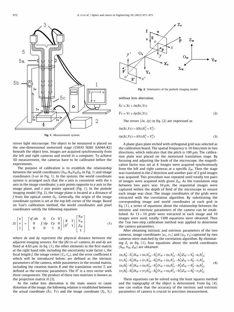
Fig. 1. Measurement system.
Fig. 2. Schematics of the pinhole imaging model.
K. Li et al. / Optics and Lasers in Engineering 50 (2012) 971–975972
stereo light microscope. The object to be measured is placed onthe one-dimensional motorized stage (CHUO SEIKI XA04A-R2)beneath the object lens. Images are acquired synchronously fromthe left and right cameras and stored in a computer. To achieve3D measurement, the cameras have to be calibrated before theexperiments.
The purpose of calibration is to establish the relationshipbetween the world coordinates (OW-XWYWZW in Fig. 1) and imagecoordinates (I-uv in Fig. 1). In the system, the world coordinatesystem is arranged such that the x axis is consistent with the x
axis in the image coordinate; y axis points opposite to y axis in theimage plane, and z axis points upward (Fig. 1). In the pinholeimaging model (Fig. 2), the image plane is located at a distance off from the optical center OC. Generally, the origin of the imagecoordinate system is set at the top left corner of the image. Basedon Tsai’s calibration method, the world coordinates and pixelcoordinates satisfy the following equation:
Zc
u
v
1
264
375¼
sf=dx 0 Cx 0
0 f=dy Cy 0
0 0 1 0
264
375 R T
0T 1
� � XW
YW
ZW
1
26664
37775 ð1Þ
where dx and dy represent the physical distance between theadjacent imaging sensors. For the JAI cv-a1 camera, dx and dy arefixed at 4.65 mm. In Eq. (1), the other elements in the first matrixat the right hand side, including the uncertainty scale factor s, thefocal length f, the image center (Cx, Cy), and the error coefficient k
which will be introduced below, are defined as the intrinsicparameters of the camera, while parameters in the second matrix,including the rotation matrix R and the translation vector T, aredefined as the extrinsic parameters. The 0T is a zero vector withthree components. The product of these two matrixes is known asthe projection matrix H [3].
As the radial lens aberration is the main source to causedistortion of the image, the following relation is established betweenthe actual coordinate ð ~Xc, ~Y cÞ and the image coordinate (XC, YC)
without lens aberration.
~Xc¼ XcþdxðXc,YcÞ
~Y c¼ YcþdyðXc,YcÞ ð2Þ
The errors (dx, dy) in Eq. (2) are expressed as
dxðXc,YcÞ ¼ kXcðX2c þY2
c Þ
dyðXc,YcÞ ¼ kYcðX2c þY2
c Þ ð3Þ
A plane glass plate etched with orthogonal grid was selected asthe calibration board. The spatial frequency is 10 lines/mm in twodirections, which indicates that the pitch is 100 mm. The calibra-tion plate was placed on the motorized translation stage. Byfocusing and adjusting the knob of the microscope, the magnifi-cation factor was set at 4. Images were acquired synchronouslyfrom the left and right cameras at a specific ZW. Then the stagewas translated in the Z direction and another pair of 2 grid imageswas acquired. This procedure was repeated until totally ten pairsof images were acquired with given ZW. As the translation stepbetween two pairs was 10 mm, the sequential images werecaptured within the depth of field of the microscope to ensureeach image was clear. The image coordinates of the grids wereextracted with the correlation algorithm. By substituting thecorresponding image and world coordinates at each grid inEq. (1), a series of equations about the relationship between theintrinsic and extrinsic parameters of the camera can be estab-lished. As 13�10 grids were extracted in each image and 10images were used, totally 1300 equations were obtained. Thenthe Tsai two-step calibration method was applied to determinethe camera parameters.
After obtaining intrinsic and extrinsic parameters of the twocameras, image coordinates (u1, v1) and (u2, v2) captured by twocameras were matched by the correlation algorithm. By eliminat-ing Zc in Eq. (1), four equations about the world coordinates(XW, YW, ZW) are obtained:
ðu1h19�h1
1ÞXWþðu1h110�h1
2ÞYWþðu1h111�h1
3ÞZW ¼ h14�u1h1
12
ðv1h19�h1
5ÞXWþðv1h110�h1
6ÞYWþðu1h111�h1
7ÞZW ¼ h18�v1h1
12
ðu2h29�h2
1ÞXWþðu2h210�h2
2ÞYWþðu2h211�h2
3ÞZW ¼ h24�u2h2
12
ðv2h29�h2
5ÞXWþðv2h210�h2
6ÞYWþðu2h211�h2
7ÞZW ¼ h28�v2h2
12
ð4Þ
These equations can be solved using the least squares methodand the topography of the object is determined. From Eq. (4),one can realize that the accuracy of the intrinsic and extrinsicparameters of camera is crucial to precision measurement.
K. Li et al. / Optics and Lasers in Engineering 50 (2012) 971–975 973
2.2. Error analysis in calibration procedure
There are two major error sources in camera calibration proce-dure. The first is caused by image positioning of the grids, and thesecond is the systematic error caused by translation stage. In thisstudy, a simulation study based on the experiment was implemented.In the study, the magnification factor of the microscope was set at4 and the field of view was 1.6 mm�1.2 mm. After the aforemen-tioned calibration procedure was conducted, the intrinsic and extrin-sic parameters of the cameras were obtained and are shown inTable 1.
For an ideal dual-camera imaging system, the distortioncoefficient (k) should be 0 and uncertainty scale factor (s) shouldbe 1. The parameters, including f, Ty, Tz in the two cameras, shouldhave the same values assuming the left and right light pathsare identical and f/Tz should satisfy the following relationship:f/Tz¼magnification factor according to the principle of similartriangles in pinhole model. As the image size is 1376�1035 pix-els, the center point (Cx, Cy) was set to be located at (688, 517.5).Thus, the parameters of the left and right cameras without errorswere constructed as listed in Table 2.
Table 1Calibration parameters of the two cameras (magnification factor¼4).
Left camera Right camera
f 556.80 584.19
k �0.000066 �0.000053
Tx �10.81 �10.41
Ty 10.25 10.54
Tz 140.59 146.36
R 0.996445 �0.00512 �0.08409 0.99936 �0.00871 0.034692
�0.006434 �0.99986 �0.01541 �0.007658 �0.99951 �0.03024
�0.083999 0.015893 �0.99634 0.034939 0.029954 �0.99894
Cx 873.75 688.00
Cy 732.32 517.50
s 0.99 0.99
Table 2Error free parameters of the two cameras (magnification factor¼4).
Left camera Right camera
f 584 584
k 0 0
Tx �10.5 �10.4
Ty 10.5 10.5
Tz 146 146
R 0.996445 �0.00512 �0.08409 0.99936 �0.00871 0.034692
�0.006434 �0.99986 �0.01541 �0.007658 �0.99951 �0.03024
�0.083999 0.015893 �0.99634 0.034939 0.029954 �0.99894
Cx 688 688
Cy 517.5 517.5
s 1 1
Fig. 3. Error analysis for
Substituting the error free calibration parameters and theactual coordinates of 10 images in Eq. (1), the error-free imagecoordinates of the grids were obtained.
2.2.1. Effects of grid positioning error
The errors of the grid positioning in the image coordinates areusually limited to a subpixel range and obey a normal statisticdistribution. In this study four sorts of subpixel positioningprecision were considered, i.e. 0.01 pixel, 0.05 pixel, 0.1 pixel,and 0.5 pixel. For instance, if an error of 0.01 pixel was consid-ered, a random error ranging within 0–0.01 pixel was introducedinto the grid image coordinates, and the intrinsic and extrinsicparameters of the cameras were calculated based on the imagecoordinates with errors. Then, the displacement components inthe world coordinate system were compared with the resultswhich were obtained based on error-free calibration parameters.The magnitudes of the maximum errors are shown in Fig. 3.
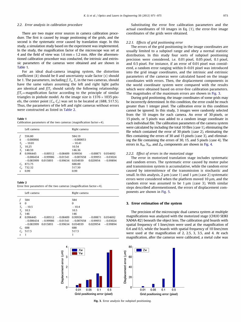
During grid positioning, the image coordinates of some grids maybe incorrectly determined. In this condition, the error could be muchgreater than 1 integer pixel. The calibration error in this conditioncannot be ignored. In this study, 3 images were randomly selectedfrom the 10 images for each camera. An error of 30 pixels, or15 pixels, or 5 pixels was added to a random image coordinate ineach individual file. The calibration parameters of the camera systemwere calculated by including the total 10 files (case 1), eliminating thefile which contained the error of 30 pixels (case 2), eliminating thefiles containing the errors of 30 and 15 pixels (case 3), and eliminat-ing the file containing the errors of 30, 15, and 5 pixels (case 4). Theerrors in XW, YW, and ZW components are shown in Fig. 4.
2.2.2. Effect of errors in the motorized stage
The error in motorized translation stage includes systematicand random errors. The systematic error caused by motor pulseand transmission system is accumulative, while the random errorcaused by intermittence of the transmission is stochastic andsmall. In this analysis, 2 mm (case 1) and 1 mm (case 2) systematicerrors were considered when the platform moved 10 mm, and therandom error was assumed to be 1 mm (case 3). With similarsteps described aforementioned, the errors of displacement com-ponents are shown in Fig. 5.
3. Error estimation of the system
The precision of the microscopic dual camera system at multiplemagnifications was analyzed with the motorized stage (CHUO SEIKIXA04A-R2) beneath the object lens. The calibration grid boards withspatial frequency of 1 lines/mm were used at the magnification of0.4 and 0.5, while the boards with spatial frequency of 10 lines/mmwere used at the magnification of 2, 2.5, 3, 3.5, and 4. At eachmagnification, after the cameras were calibrated, a metal cube was
subpixel positioning.

Fig. 4. Error analysis for incorrect grid positioning.
Fig. 5. Error analysis for errors in motorized stage.
Table 3Precision of the microscopic dual-camera system at multiple magnifications.
Magnification Field of view
(mm2)
Error in displacement Relative
error
Xw
(mm)
YW
(mm)
ZW
(mm)
ZW (%)
0.4 16�12 0.38 0.63 5.50 2.12
0.5 12.5�9 0.29 0.47 4.28 1.04
2 3.1�2.3 0.09 0.10 1.66 3.93
2.5 2.5�1.8 0.08 0.16 1.37 4.05
3 2.1�1.6 0.08 0.19 1.17 2.67
3.5 1.8�1.4 0.08 0.17 1.08 3.01
4 1.6�1.2 0.08 0.18 1.14 3.94
K. Li et al. / Optics and Lasers in Engineering 50 (2012) 971–975974
placed on a 3D translation stage and subjected to given movements.A pair of images from left and right cameras was acquired simu-ltaneously and the displacement components in three directionswere calculated through a standard 3D DIC algorithm. Totally, 10measurements were conducted at each magnification. The precisionof the microscopic dual-camera system at multiple magnifications islisted in Table 3.
Theoretically, the precision of the system is related to themagnification number. One can find that the error in displace-ment decreases when the magnification number increases from0.4 to 2. However, the precision does not change much withhigher magnification (2–4). This is due to the presence of errorwithin the motorized stage. To achieve higher precision, a moreprecise translation stage is desired.
4. Measurement of surface morphology of human incisors
Since the surface area of incisor was around 8�10 mm2, thefield of view of the microscope described in Section 2.1 was set at16�12 mm2. During camera calibration, the precision grid board,
which was placed on the motorized stage, was controlled to movein one-way direction to reduce the error from lead backlash andpairs of images were acquired at every 50 mm of movement. Sincethe accumulative lead error in one-way direction is less than5 mm in 10 mm length, the error introduced in every 50 mmincrement was within 0.025 mm from a linear transform. Byimplementing the Tsai calibration, the intrinsic and extrinsicparameters of the two cameras were determined. Errors wereestimated at 0.6 mm for in-plane displacement, and 5.5 mm in out-of-plane direction. Plaster incisors were duplicated by techniciansin West China College of Stomatology, Sichuan University. Thesurface was sprayed with thin black speckles coating to facilitatethe analysis of DIC. The prepared incisor was then placed underthe objective lens of the stereo microscope. The images acquiredfrom left and right cameras were used to measure the surfacemorphology of the human incisor. The 3D profile of the labialsurface of the incisor is shown in Fig. 6. It was found that therewere two main grooves on the labial surface. They were located2.85 mm apart. The depth and length for the long groove were83 mm and 5.28 mm, respectively, and 40 mm and 4.24 mm for theshort groove, respectively.
5. Discussion
This study developed a microscopic profile/displacement mea-surement system based on dual-camera DIC. The system includesa stereo light microscope with optical outputs, 2 video cameras,and a motorized translation stage. It was found that no matterwhat kinds of errors are introduced in the calibration parameters,the errors of the displacement component in ZW are usually 10times larger than those in XW and YW directions. This agrees withmany reports on 3D measurement [11]. However, the magnitudesof errors are dependent on the errors introduced in the calibrationprocesses. Considering the error introduced in grid positioning,the errors in displacement measurement are not considerable if

Fig. 6. 3D profile of the labial surface of the incisor.
K. Li et al. / Optics and Lasers in Engineering 50 (2012) 971–975 975
they are due to imprecise subpixel positioning. The incorrect gridpositioning could cause large variation in displacement measure-ment, as shown in Fig. 4. However, it would also cause thedeviation error in the grid image coordinates as the grid coordi-nates are supposed to be equally spaced in rows and columns.Thus, the coordinate data file which contains the incorrect gridcoordinates could be eliminated based on this criterion.
The measurement results were largely dependent on the errorsintroduced in the translation stage. As the motorized stage is idealfor automatic measurement, the systematic errors should beespecially considered. Note that the magnitudes (1 mm and2 mm) of errors are common in most commercial motorizedstages. It is found that the errors in displacement measurementare about 100 times larger than those due to incorrect gridpositioning. Precise stages with feedback are recommended foraccurate measurement.
During the calibration process, the errors introduced in gridpositioning and stage translation would cause the singularityproblem in solving Eq. (1). It was found that it can be avoided bychanging the initial values of the image center (Cx, Cy). Althoughthe determined intrinsic parameters are varied with the errors,the parameter f/Tz, can be used to identify if the calibration isproperly conducted, as the ratio of f to Tz should be equal to themagnification factor of microscope.
6. Conclusions
This paper discussed two main error sources, i.e. grid position-ing and stage translation. It is found that the displacement errorin ZW is 10 times larger than those in XW and YW directions nomatter what sorts of errors are introduced. The error introducedby the motorized stage could cause severe errors in displacementmeasurement. The ratio of f to Tz can be used to determine if the
camera calibration is precise, since it should be equal to themagnification factor.
Acknowledgments
This research is supported by the National Science Foundationof China Grant # 11172161 and # 10902066, the Science andTechnology Commission of Shanghai Municipality Grant#10410701900 and #11195820900, the Innovation Program ofShanghai Municipal Education Commission #12ZZ092, the StateKey Laboratory of Oral Diseases (Sichuan University) by GrantSKLODSCU2009KF03, and the Shanghai Leading Academic Disci-pline Project #S30106.
References
[1] Pan B, Xie HM, Tao H, Asundi A. Measurement of coefficient of thermalexpansion of films using digital image correlation method. Polym Test2009;28(1):75–83.
[2] Reu PL, Miller TJ. The application of high-speed digital image correlation.J Strain Anal Eng Des 2008;43(8):673–88.
[3] Yoneyama S, Kitagawa A, Iwata S, Tani K, Kikuta H. Bridge deflectionmeasurement using digital image correlation. Exp Tech 2007;31(1):34–40.
[4] Zhang D, Arola D. Applications of digital image correlation to biologicaltissues. J Biomed Opt 2004;9(4):691–9.
[5] Pan B, Wu DF, Xia Y. High-temperature field measurement by combingtransient aerodynamic heating system and reliability-guided digital imagecorrelation. Opt Lasers Eng 2010;48(9):841–8.
[6] Zhang D, Nazari A, Soappman M, Bajaj D, Arola D. Methods for examining thefatigue and fracture behavior of hard tissues. Exp Mech 2007;47(3):325–36.
[7] Pan B, Qian KM, Xie HM, Asundi A. Two-dimensional digital image correlationfor in-plane displacement and strain measurement: a review. Meas SciTechnol 2009;20:062001.
[8] Tay CJ, Quan C, Huang YH, Fu Y. Digital image correlation for whole fieldout-of-plane displacement measurement using a single camera. Opt Commun2005;251(1–3):23–36.
[9] Shih MH, Sung W, Bacinskas D. Development of Digital Imagine Correlation(DIC) method for three-dimensional rugged surface of construction material.Adv Mater Res 2011;243–249:5907–10.
[10] Orteu J-J, Bugarin F, Harvent J, Robert L, Velay V. Multiple-camera instru-mentation of a single point incremental forming process pilot for shape and3D displacement measurements: methodology and results. Exp Mech2011;51(4):625–39.
[11] Luo PF, Huang FC. Application of stereo vision to the study of mixed-modecrack-tip. Opt Lasers Eng 2000;33(5):349–68.
[12] Ke X, Sutton MA, Lessner SM, Yost M. Robust stereo vision and calibrationmethodology for accurate three-dimensional digital image correlation mea-surements on submerged objects. J Strain Anal Eng Des 2008;43(8):689–704.
[13] Yu QF, Shang Y. Videometrics: principles and researches. Beijing: SciencePress; 2009.
[14] Faig W. Calibration of close-range photogrammetry systems: mathematicalformulation. Photogramm Eng Remote Sens 1975;41(12):1479–86.
[15] Abdel-Aziz YI, Karara HM. Direct linear transformation into object spacecoordinates in close-range photogrammetry. Urbana: Proceedings of SympClose-Range.
[16] Tsai RY. A versatile camera calibration technique for high accuracy 3Dmachine vision metrology using off-the-shelf TV cameras and lenses. IEEE JRobotics Autom 1987;ra-3(4):323–44.
[17] Zhang Z. A flexible new technique for camera calibration. IEEE Trans PatternAnal Mach Intell 2000;22(11):1330–4.
[18] Schreier HW, Garcia D, Sutton MA. Advances in light microscope stereovision. Exp Mech June 2004;44(3):278–88.
[19] Larsson L, Sjodahl M, Thuvander F. Microscopic 3-D displacement fieldmeasurements using digital speckle photography. Opt Lasers Eng2004;41(5):767–77.
[20] Zhu T, Sutton MA, Li N, Orteu J-J, Cornille N, Li X, Reynolds AP. Quantitativestereovision in a scanning electron microscope. Exp Mech 2011;51(1):97–109.