Embed Size (px)
Citation preview

(A2LA Cert. No. 3332.01) Revised 09/19/2017 Page 1 of 11
SCOPE OF ACCREDITATION TO ISO/IEC 17025:2005
TRESCAL, INC. 4407 Charleroi Street
Montreal, Quebec, H1H 1T6 Canada Christian Lefroit Phone: 514 329 3242 x 229
CALIBRATION
Valid until: August 31, 2018 Certificate Number: 3332.01 In recognition of the successful completion of the A2LA evaluation process, accreditation is granted to this laboratory to perform the following calibrations1: I. Dimensional
Parameter/Equipment
Range
CMC2, 5 ()
Comments
Gage Block Length – Steel, Rectangular & Square
Up to 4 in (4 to 20) in Up to 100 mm (100 to 500) mm
(2.8 + 1.6L) μin (2.5 + 2.9L) μin (0.061 + 0.002L) μm (0.080 + 0.0021L) μm
Comparison method w/ a reference gage block set ANSI /ASME B89.1.2M, FED SPEC GGG-G-15C
Cylindrical Ring Gage –
Diameter
Up to 8 in Up to 200 mm
(20 + 6D) μin (0.5 + 0.006D) μm
Comparison method w/ ring gages and Mahr Model 828. ANSI /ASME B89.1.6M
Cylindrical Plug Gage –
Diameter
Up to 8 in Up to 200 mm
(12 + 6D) μin (0.31 + 0.006D) μm
ANSI /ASME B89.1.5
(A2LA Cert. No. 3332.01) Revised 09/19/2017 Page 2 of 11
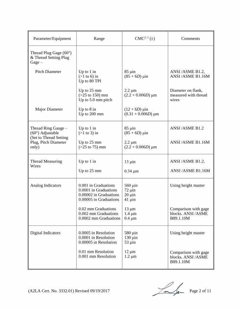
Parameter/Equipment
Range
CMC2, 5 ()
Comments
Thread Plug Gage (60°) & Thread Setting Plug Gage –
Pitch Diameter Major Diameter
Up to 1 in (>1 to 6) in Up to 80 TPI Up to 25 mm (>25 to 150) mm Up to 5.0 mm pitch Up to 8 in Up to 200 mm
85 μin (85 + 6D) μin 2.2 μm (2.2 + 0.006D) μm (12 + 6D) μin (0.31 + 0.006D) μm
ANSI /ASME B1.2, ANSI /ASME B1.16M Diameter on flank, measured with thread wires
Thread Ring Gauge – (60°) Adjustable (Set to Thread Setting Plug, Pitch Diameter only)
Up to 1 in (>1 to 3) in Up to 25 mm (>25 to 75) mm
85 μin (85 + 6D) μin 2.2 μm (2.2 + 0.006D) μm
ANSI /ASME B1.2 ANSI /ASME B1.16M
Thread Measuring Wires
Up to 1 in Up to 25 mm
13 μin 0.34 μm
ANSI /ASME B1.2, ANSI /ASME B1.16M
Analog Indicators
0.001 in Graduations 0.0001 in Graduations 0.00002 in Graduations 0.00005 in Graduations 0.02 mm Graduations 0.002 mm Graduations 0.0002 mm Graduations
560 μin 72 μin 20 μin 41 µin 13 μm 1.4 μm 0.4 μm
Using height master Comparison with gage blocks. ANSI /ASME B89.1.10M
Digital Indicators
0.0005 in Resolution 0.0001 in Resolution 0.00005 in Resolution 0.01 mm Resolution 0.001 mm Resolution
580 μin 130 μin 53 µin 12 μm 1.2 μm
Using height master
Comparison with gage blocks. ANSI /ASME B89.1.10M

(A2LA Cert. No. 3332.01) Revised 09/19/2017 Page 3 of 11
Parameter/Equipment
Range
CMC2, 5 ()
Comments
Micrometers – Outside
Up to 6 in (6 to 40) in Up to 150 mm (150 to 2000) mm
(41 + 1.8L) μin (25 + 5.2L) μin (1.1 + 0.0018L) μm (0.63 + 0.0052L) μm
CAN/CGSB-39-18, comparison with gage blocks
Micrometer – Inside
Up to 24 in (24 to 60) in Up to 600 mm (600 to 1500) mm
(100 + 7.4L) μin (100 + 8.5L) μin (2.6 + 0.007L) μm (2.6 + 0.008L) μm
CAN/CGSB-39-18, comparison with gage blocks
Micrometer – Depth
Up to 12 in Up to 300 mm
(120 + 12L) μin (2.9 + 0.012L) μm
CAN/CGSB-39-18, comparison with gage blocks
Micrometer – Three Point Internal
Up to 4 in Up to 100 mm
(81 + 3L) μin (2.1 + 0.003L) μm
Comparison with ring gages
Micrometer – Setting Standards
Up to 60 in Up to 1500 mm
(26 + 9L) μin (0.67 + 0.009L) μm
Comparison with gage blocks
Caliper – Outside
Up to 40 in Up to 1000 mm
(300 + 2L) μin (7.6 + 0.002L) μm
CAN/CGSB-39-19, comparison with gage blocks
Caliper – Inside
Up to 12 in Up to 300 mm
330 μin 8.2 μm
Comparison with gage blocks
Caliper – Depth
Up to 12 in Up to 300 mm
330 μin 8.2 μm
Comparison with gage blocks
Height Gauges
Up to 40 in Up to 1000 mm
(100 + 3.5L) μin (2.6 + 0.0035L) μm
FED SPEC GGG-G-111C with comparison with gage blocks
(A2LA Cert. No. 3332.01) Revised 09/19/2017 Page 4 of 11
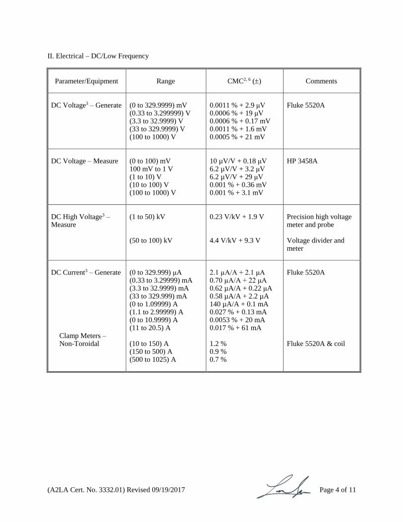
II. Electrical – DC/Low Frequency
Parameter/Equipment
Range
CMC2, 6 ()
Comments
DC Voltage3 – Generate
(0 to 329.9999) mV (0.33 to 3.299999) V (3.3 to 32.9999) V (33 to 329.9999) V (100 to 1000) V
0.0011 % + 2.9 μV 0.0006 % + 19 μV 0.0006 % + 0.17 mV 0.0011 % + 1.6 mV 0.0005 % + 21 mV
Fluke 5520A
DC Voltage – Measure
(0 to 100) mV 100 mV to 1 V (1 to 10) V (10 to 100) V (100 to 1000) V
10 µV/V + 0.18 μV 6.2 µV/V + 3.2 μV 6.2 µV/V + 29 μV 0.001 % + 0.36 mV 0.001 % + 3.1 mV
HP 3458A
DC High Voltage3 – Measure
(1 to 50) kV (50 to 100) kV
0.23 V/kV + 1.9 V 4.4 V/kV + 9.3 V
Precision high voltage meter and probe Voltage divider and meter
DC Current3 – Generate
Clamp Meters – Non-Toroidal
(0 to 329.999) μA (0.33 to 3.29999) mA (3.3 to 32.9999) mA (33 to 329.999) mA (0 to 1.09999) A (1.1 to 2.99999) A (0 to 10.9999) A (11 to 20.5) A (10 to 150) A (150 to 500) A (500 to 1025) A
2.1 µA/A + 2.1 μA 0.70 µA/A + 22 μA 0.62 µA/A + 0.22 μA 0.58 µA/A + 2.2 µA 140 µA/A + 0.1 mA 0.027 % + 0.13 mA 0.0053 % + 20 mA 0.017 % + 61 mA 1.2 % 0.9 % 0.7 %
Fluke 5520A Fluke 5520A & coil

(A2LA Cert. No. 3332.01) Revised 09/19/2017 Page 5 of 11
Parameter/Equipment
Range
CMC2, 6 ()
Comments
DC Current – Measure
(0 to 100) nA 100 nA to 1 μA (1 to 10) μA (10 to 100) μA 100 μA to 1 mA (1 to 10) mA (10 to 100) mA 100 mA to 1 A (1 to 20) A 10 μA to 200 mA
24 µA/A + 0.03 nA 16 µA/A + 0.03 nA 16 µA/A + 0.08 nA 17 µA/A + 0.001 µA 16 µA/A + 0.012 µA 16 µA/A + 0.11 µA 27 µA/A + 0.39 µA 130 µA/A + 17 µA 420 µA/A + 220 µA 0.30 %
HP 3458A
Fluke 8508A
Hipot leakage current using a digital meter
Electrical Simulation of Temperature Indicators RTD simulation3
(-200 to 660) °C
0.0065 % + 0.04 °C
Fluke 5520A
AC Power3 –
(0.2 to 20.5) A (45 to 65) Hz
(0.033 to 1020) V
0.08 %
Fluke 5520A
DC Power3–
(0.2 to 20.5) A
(1 to 1020) V
0.035 %
Fluke 5520A
Electrical Simulation of Temperature Indicators Thermocouple Simulation3 –
Type J Type K Type T Type N Type S Type B Type E
(-210 to 1200) ºC (-200 to 1372) ºC (-250 to 400) ºC (-200 to 1300) ºC (0 to 1767) °C (600 to 1820) °C (-250 to 1000) °C
0.010 % + 0.19 °C 0.006 % + 0.15 °C 0.055 % + 0.28 °C 0.006 % + 0.24 °C 0.004 % + 0.37 °C 0.006 % + 0.31 °C 0.017 % + 0.23 °C
Fluke 5520A
(A2LA Cert. No. 3332.01) Revised 09/19/2017 Page 6 of 11
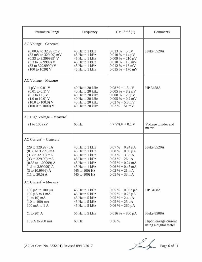
Parameter/Range
Frequency
CMC2, 4, 6 ()
Comments
AC Voltage – Generate
(0.0032 to 32.99) mV (33 mV to 329.99) mV (0.33 to 3.299999) V (3.3 to 32.9999) V (33 to 329.9999) V (100 to 1020) V
45 Hz to 1 kHz 45 Hz to 1 kHz 45 Hz to 1 kHz 45 Hz to 1 kHz 45 Hz to 1 kHz 45 Hz to 1 kHz
0.013 % + 5 µV 0.010 % + 14 µV 0.009 % + 210 µV 0.010 % + 1.8 mV 0.012 % + 16 mV 0.015 % + 170 mV
Fluke 5520A
AC Voltage – Measure
1 µV to 0.01 V (0.01 to 0.1) V (0.1 to 1.0) V (1.0 to 10.0) V (10.0 to 100.0) V (100.0 to 1000) V
40 Hz to 20 kHz 40 Hz to 20 kHz 40 Hz to 20 kHz 40 Hz to 20 kHz 40 Hz to 20 kHz 40 Hz to 20 kHz
0.08 % + 1.5 µV 0.005 % + 8.2 µV 0.008 % + 20 µV 0.005 % + 0.2 mV 0.02 % + 5.8 mV 0.02 % + 51 mV
HP 3458A
AC High Voltage – Measure3
(1 to 100) kV
60 Hz
4.7 V/kV + 0.1 V
Voltage divider and meter
AC Current3 – Generate
(29 to 329.99) µA (0.33 to 3.299) mA (3.3 to 32.99) mA (33 to 329.99) mA (0.33 to 1.09999) A (1.1 to 2.99999) A (3 to 10.9999) A (11 to 20.5) A
AC Current3 – Measure
100 pA to 100 µA 100 µA to 1 mA (1 to 10) mA (10 to 100) mA 100 mA to 1 A (1 to 20) A 10 μA to 200 mA
45 Hz to 1 kHz 45 Hz to 1 kHz 45 Hz to 1 kHz 45 Hz to 1 kHz 45 Hz to 1 kHz 45 Hz to 1 kHz (45 to 100) Hz (45 to 100) Hz 45 Hz to 1 kHz 45 Hz to 5 kHz 45 Hz to 5 kHz 45 Hz to 5 kHz 45 Hz to 5 kHz 55 Hz to 5 kHz 60 Hz
0.07 % + 0.24 µA 0.08 % + 0.69 µA 0.03 % + 3.3 µA 0.03 % + 26 µA 0.05 % + 0.24 mA 0.06 % + 0.45 mA 0.02 % + 21 mA 0.05 % + 33 mA
0.05 % + 0.033 µA 0.05 % + 0.25 µA 0.05 % + 2.4 µA 0.05 % + 25 µA 0.06 % + 260 µA 0.016 % + 800 µA 0.36 %
Fluke 5520A HP 3458A Fluke 8508A Hipot leakage current using a digital meter

(A2LA Cert. No. 3332.01) Revised 09/19/2017 Page 7 of 11
Parameter/Range
Frequency
CMC2, 6 ()
Comments
Clamp Meters – Toroidal
(10 to 150) A (150 to 500) A (500 to 1025) A
Clamp Meters – Other Than Toroidal
(40 to 150) A (150 to 500) A (500 to 1025) A
(45 to 65) Hz (45 to 65) Hz (45 to 65) Hz (45 to 65) Hz (45 to 65) Hz (45 to 65) Hz
0.6 % 0.4 % 0.3 % 1.4 % 1.3 % 0.8 %
Fluke 5520A & coil Fluke 5520A & coil
Parameter/Equipment
Range
CMC2, 6 ()
Comments
Resistance3 –
Generate
Fixed Points
(0 to 10.9999) Ω (11 to 32.999) Ω (33 to 109.9999) Ω (110 to 329.9999) Ω 330 Ω to 1.099999 kΩ (1.1 to 3.29999) kΩ (3.3 to 10.99999) kΩ (11 to 32.99999) kΩ (33 to 109.9999) kΩ (110 to 329.9999) kΩ 330 kΩ to 1.099999 MΩ (1.1 to 3.299999) MΩ (3.3 to 10.99999) MΩ (11 to 32.99999) MΩ (33 to 109.9999) MΩ (110 to 329.9999) MΩ (330 to 1100) MΩ 10 μΩ 100 μΩ 1 mΩ 10 mΩ 100 mΩ 1 Ω 10 Ω
0.0017 % + 0.78 mΩ 0.0032 % + 1.1 mΩ 0.0018 % + 2.0 mΩ 0.0023 % + 2.1 mΩ 0.0080 % + 18 mΩ 0.0018 % + 77 mΩ 0.0017 % + 180 mΩ 0.0023 % + 540 mΩ 0.0018 % + 1.7 Ω 0.0025 % + 5.1 Ω 0.0025 % + 13 Ω 0.0046 % + 90 Ω 0.012 % + 380 Ω 0.019 % + 4.7 kΩ 0.033 % + 24 kΩ 0.23 % + 0.41 MΩ 2.0 % + 0.4 MΩ 0.27 % 0.027 % 0.017 % 0.015 % 0.014 % 0.013 % 0.013 %
Fluke 5520A
Standard resistors

(A2LA Cert. No. 3332.01) Revised 09/19/2017 Page 8 of 11
Parameter/Range
Frequency
CMC2, 4, 6 ()
Comments
Resistance3 – Measure
100 µΩ to 10 Ω (10 to 100) Ω 100 Ω to 1 kΩ (1 to 10) kΩ (10 to 100) kΩ 100 kΩ to 1) MΩ (1 to 10) MΩ (10 to 100) MΩ (10 to 100) μΩ (0.1 to 1) mΩ (1 to 10) mΩ (10 to 100) mΩ 100 mΩ to 1 Ω (1 to 10) Ω
0.001 % + 0.04 mΩ 0.001 % + 0.54 mΩ 0.001 % + 3.2 mΩ 0.001 % + 0.03 mΩ 0.001 % + 0.3 mΩ 0.0017 % + 7.2 Ω 0.004 % + 250 Ω 0.04 % + 6.7 kΩ 0.013 % 0.013 % 0.013 % 0.004 % 0.003 % 0.002 %
HP 3458A Standard resistors and transfer method
Capacitance3
(0.19 to 0.3999) nF (0.4 to 1.099) nF (1.1 to 3.2999) nF (3.3 to 10.9999) nF (11 to 32.9999) nF (33 to 109.999) nF (110 to 329.999) nF 0.33 µF to 1.09999 µF (1.1 to 3.29999) μF (3.3 to 10.9999) μF (11 to 32.9999) μF (33 to 109.999) µF (110 to 329.999) µF 0.33µF to 1.09999 mF (1.1 to 3.2999) mF (3.3 to 10.9999) mF (11 to 32.9999) mF (33 to 110) mF
10 Hz to 10 kHz 10 Hz to 10 kHz 10 Hz to 3 kHz 10 Hz to 1 kHz 10 Hz to 1 kHz 10 Hz to 1 kHz 10 Hz to 1 kHz (10 to 600) Hz (10 to 300) Hz (10 to 150) Hz (10 to 120) Hz (10 to 80) Hz (0 to 50) Hz (0 to 20) Hz (0 to 6) Hz (0 to 2) Hz (0 to 0.6) Hz (0 to 0.2) Hz
0.43 % + 0.008 nF 0.38 % + 0.008 nF 0.44 % + 0.007 nF 0.11 % + 0.017 nF 0.22 % + 0.075 nF 0.20 % + 0.08 nF 0.19 % + 0.25 nF 0.20 % + 0.3 nF 0.20 % + 2.4 nF 0.20 % + 8.2 nF 0.38 % + 6.4 nF 0.37 % + 74 nF 0.35 % + 0.24 µF 0.35 % + 0.78 µF 0.35 % + 2.3 µF 0.41 % + 1.3 µF 0.69 % + 11 µF 0.82 % + 140 µF
Fluke 5520A

(A2LA Cert. No. 3332.01) Revised 09/19/2017 Page 9 of 11
III. Mechanical
Parameter/Equipment
Range
CMC2, 4 ()
Comments
Torque Wrenches & Screwdrivers: Clockwise
5 in·ozf to 1000 in·lbf (10 to 250) ft·lbf (250 to 2000) ft·lbf
0.55 % 0.55 % 0.55 %
Electronic transducer system
Indirect Verification of Rockwell Hardness Testers3
HRBW:
< 60 HRBW (≥ 60 to 79) HRBW ≥ 80 HRBW
HRC:
< 35 HRC (≥ 35 to < 60) HRC ≥ 60 HRC
1.1 HRBW 0.67 HRBW 0.49 HRBW 0.41 HRC 0.37 HRC 0.35 HRC
Indirect verification per ASTM E18
Scales and Balances3 –
Fixed Points
(1 to 500) mg
1g
2 g
3 g
5 g
10 g
20 g
30 g
50 g
100 g
200 g
300 g
500 g
1 kg
2 kg
5 kg
10 kg
0.012 mg 0.05 mg 0.04 mg 0.04 mg 0.04 mg 0.04 mg 0.059 mg
0.086 mg
0.087 mg
0.14 mg
0.29 mg
0.59 mg
0.87 mg
1.4 mg
3.0 mg
5.9 mg
14 mg
29 mg
ASTM Class 1 weights

(A2LA Cert. No. 3332.01) Revised 09/19/2017 Page 10 of 11
Parameter/Equipment
Range
CMC2, 4 ()
Comments
Pressure Indicators and Gauges –
Pneumatic Pressure Hydraulic Pressure Hydraulic Pressure Barometric Pressure
(0 to 5) psi (10 to 800) psi (800 to 16 000) psi (70 to 110) kPa
0.013 % + 0.002 psi 0.045 % 0.045 % 0.010 %
Pressure calibrator Deadweight tester Deadweight tester Pressure calibrator
Vacuum
(0 to -14.5) psig (0 to -29.5) inHg
0.010 % + 0.002 psi 0.010 % + 0.004 inHg
Pressure calibrator
IV. Thermodynamics
Parameter/Range
Range
CMC2, 4 ()
Comments
Relative Humidity3 –
Measuring Equipment
(10 to 90) % RH
1.0 %
Humidity generator
Temperature –
Liquid in Glass Thermometers Digital thermometer: Thermocouples /Thermocouples3 Digital Thermometer: Resistance Infrared Thermometer
Air Probe Thermometer
(-80°C to 250) °C (-40 to 50) °C (50 to 300) °C (300 to 700) °C (700 to 1200) °C (-80 to 50) °C (50 to 250) °C
(35 to 100) ºC (100 to 350) ºC (350 to 500) ºC (10 to 45) ºC
0.039 °C 0.44 °C 0.56 °C 0.90 °C 4.7 °C 0.025 °C 0.038 °C
0.6 ºC 0.29 % + 0.8 ºC 0.29 % + 1.5 ºC 0.24 °C
Liquid calibration baths w/ SPRT Metrology wells (dry) Thermocouple furnace Liquid calibration baths w/ SPRT Infrared calibrator Environmental chamber & SPRT
(A2LA Cert. No. 3332.01) Revised 09/19/2017 Page 11 of 11
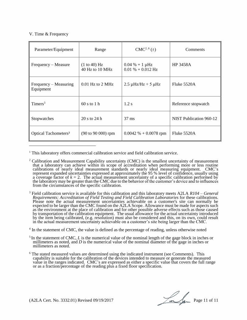
V. Time & Frequency
Parameter/Equipment
Range
CMC2, 6 ()
Comments
Frequency – Measure
(1 to 40) Hz 40 Hz to 10 MHz
0.04 % + 1 µHz 0.01 % + 0.012 Hz
HP 3458A
Frequency – Measuring Equipment
0.01 Hz to 2 MHz
2.5 µHz/Hz + 5 μHz
Fluke 5520A
Timers3
60 s to 1 h
1.2 s
Reference stopwatch
Stopwatches
20 s to 24 h
37 ms
NIST Publication 960-12
Optical Tachometers³
(90 to 90 000) rpm
0.0042 % + 0.0078 rpm
Fluke 5520A
______________________________ 1 This laboratory offers commercial calibration service and field calibration service. 2 Calibration and Measurement Capability uncertainty (CMC) is the smallest uncertainty of measurement
that a laboratory can achieve within its scope of accreditation when performing more or less routine calibrations of nearly ideal measurement standards or nearly ideal measuring equipment. CMC’s represent expanded uncertainties expressed at approximately the 95 % level of confidence, usually using a coverage factor of k = 2. The actual measurement uncertainty of a specific calibration performed by the laboratory may be greater than the CMC due to the behavior of the customer’s device and to influences from the circumstances of the specific calibration.
3 Field calibration service is available for this calibration and this laboratory meets A2LA R104 – General Requirements: Accreditation of Field Testing and Field Calibration Laboratories for these calibrations. Please note the actual measurement uncertainties achievable on a customer's site can normally be expected to be larger than the CMC found on the A2LA Scope. Allowance must be made for aspects such as the environment at the place of calibration and for other possible adverse effects such as those caused by transportation of the calibration equipment. The usual allowance for the actual uncertainty introduced by the item being calibrated, (e.g. resolution) must also be considered and this, on its own, could result in the actual measurement uncertainty achievable on a customer’s site being larger than the CMC.
4 In the statement of CMC, the value is defined as the percentage of reading, unless otherwise noted 5 In the statement of CMC, L is the numerical value of the nominal length of the gage block in inches or
millimeters as noted, and D is the numerical value of the nominal diameter of the gage in inches or millimeters as noted.
6 The stated measured values are determined using the indicated instrument (see Comments). This
capability is suitable for the calibration of the devices intended to measure or generate the measured value in the ranges indicated. CMC’s are expressed as either a specific value that covers the full range or as a fraction/percentage of the reading plus a fixed floor specification.
For the calibrations to which this accreditation applies, please refer to the laboratory’s Calibration Scope of Accreditation.
Accredited Laboratory
A2LA has accredited
TRESCAL, INC. Montreal-Nord, Québec H1H 1T6, CANADA
for technical competence in the field of
Calibration
This laboratory is accredited in accordance with the recognized International Standard ISO/IEC 17025:2005
General requirements for the competence of testing and calibration laboratories. This laboratory also meets R205 – Specific
Requirements: Calibration Laboratory Accreditation Program. This accreditation demonstrates technical competence for a
defined scope and the operation of a laboratory quality management system
(refer to joint ISO-ILAC-IAF Communiqué dated 8 January 2009).
Presented this 11th day of July 2016.
_______________________
President and CEO
For the Accreditation Council
Certificate Number 3332.01
Valid to August 31, 2018


![epssweden.comepssweden.com/files/Stop [VENS] and Regulating Valves [VENR] acc.pdf · asme/ansi b16.10 asme-ansi b16.5 asme-ansi b16.10 asme/ansi b16.25 ... 14 43 85 128 48 96 144](https://img.dokumen.tips/doc/110x75/5a9ff4687f8b9a8e178d6630/vens-and-regulating-valves-venr-accpdfasmeansi-b1610-asme-ansi-b165-asme-ansi.jpg)