Embed Size (px)
Citation preview

IOSR Journal of Mechanical and Civil Engineering (IOSR-JMCE)
e-ISSN: 2278-1684,p-ISSN: 2320-334X, Volume 11, Issue 1 Ver. I (Jan. 2014), PP 13-24
www.iosrjournals.org
www.iosrjournals.org 13 | Page
Calculations of Temperature Decay for Industrial Chimney by
Using Modified Analytical Model
M. Khalil Bassiouny, * A. A. Hussien,*Mostafa El Shafie ** *Mechanical Power Engineering Department, Faculty of Engineering Minoufiya University, Shebin El-Kom,
Egypt
**Mechanical Maintenance Engineer at El-Araby for Lighting Technology Company
Abstract: The engineering design of industrial chimneys requires predicting the temperature decay of exhaust
gases along the walls of chimney. This paper investigates the practical calculation of the thermal performance
of industrial chimneys which leads to estimating the static draft and the bulk temperature of combustion gases at
the chimney's exit for determining the air pollution levels in the vicinity of the stack.
A modified analytical model is used to obtain accurate heat transfer results. Heat transfer processes involving
the internal convection heat transfer, external heat transfer to the surrounding and conduction heat transfer,
which takes into account fouling resistance are considered.
The present modified analytical model provides a good estimation of the bulk temperature and the
outside wall temperature compared with that computed using1-D lumped model (Cortes model). The present
modified model is validated with published theoretical and experimental data. The validation shows that the
present modified model is more accurate than 1-D lumped model (Cortes model). The paper describes the
thermal calculation procedures of industrial chimneys using the standard heat transfer correlations. The
calculation procedures are easy to apply by design engineers in the field of thermal design of chimneys. Also,
comparison between the present modified model and the previous 1-D lumped model with recent experimental
data measured at the glass furnace chimney at El-Araby for Lighting Technology (glass factory) is discussed.
Keywords: Draught system, Chimney design, Modified model, El-Araby chimney, Chimney calculation
Nomenclature
Ai inner cross-sectional area of the duct
Cpi specific heat of combustion gases
De outside diameter of chimney
Di inside diameter of chimney
g acceleration of gravity
Gre, L external Grashof number based on
L, g βe (Tw,e-T∞)L3/νe2
he local, external convective coefficient hi local, internal convective coefficient
ke thermal conductivity of air ki thermal conductivity of flue gas
kw thermal conductivity of the chimney wall
kf fouling thermal conductivity kst thermal conductivity of steel
kins thermal conductivity of insulation
f friction factor L axial station; chimney height
dimensionless L, L/Ri Pei
m. flue gas mass flow rate
Nue local, external Nusselt number, heDe/ke Nue streamwise mean of Nue
streamwise mean Nusselt number based
on height L, (L/De)Nue Nueq local, equivalent Nusselt number, UD/ki
streamwise mean of Nueq
Nui local, internal Nusselt number, hiDi/ki
stream wise mean of Nui
Pei Péclet number, ReiPri=4m.Cpi/kiπDi=wDi/αi
Pre Prandtl number of the ambient air
Pri Prandtl number of the flue gas qr radiative heat flux
r radial coordinate
R chimney radius Ri inner radius

Calculations Of Temperature Decay For Industrial Chimney By Using Modified Analytical Model
www.iosrjournals.org 14 | Page
Rae,L external Rayleigh number based on L, gβe(Tw,e-
T∞)L3/νeαe Rae,o external Rayleigh number based on inlet temperature,
gβe(To-T∞)D3e / νeαe
Rae,w external Rayleigh number based on wall temperature, gβe(Tw,e-T∞)D3
e / νeαe
Ree external Reynolds number based on wind velocity,
u∞De/νe Rei internal Reynolds number, 4m./µiπDi=uDi/νi
T(r,z) local temperature of combustion gases
Tb bulk temperature of combustion gases To flue gas inlet temperature
Tr effective radiating temperature of the surroundings
Tw wall temperature Tw,e outer surface temperature
Tw,i inner surface temperature
T∞ ambient air temperature U local, overall heat transfer coefficient
u∞ wind velocity component normal to the chimney axis
V(r) axial velocity of combustion gases z axial coordinate
Z dimensionless z, z/RiPei
Gz Graetz number
Greek symbols αe air thermal diffusivity αi thermal diffusivity of combustion gases
βe thermal expansion coefficient of air
εe outside wall emissivity ke thermal entrance factor
kp temperature profile factor kt transition regime factor
γi dynamic viscosity of the combustion gases
νi kinematic viscosity of the combustion gases νe air kinematic viscosity
θb dimensionless Tb, (Tb-T∞)/(To-T∞)
θw dimensionless Tw, (Tw-T∞)/(To-T∞) θw,e dimensionless Tw,e, (Tw,e-T∞)/(To-T∞)
θw,i dimensionless Tw,i, (Tw,i- T∞)/(To-T∞)
ρi combustion gases density σ Stephan-Boltzmann constant
ξ transverse curvature coordinate
Subscripts e ambient air; outer side i combustion gases; inner side
L based on length L
w wall cyl cylinder
forc forced convection
plate flat plate mix mixed convection
free natural convection
rad thermal radiation
g combustion gases
I. Introduction The chimney is an important structure in the industrial activities which use conventional fuels. Chimney
is the last structure in the flue gases path and used for removing pollutants resulting from the combustion of
fuel. It safeguards people at or close to the zone from high concentrations of those pollutants by providing
dilution of the pollutants in the atmosphere. Chimney structures should be able to contain this flue gas without
being deteriorated. At present time many considerations are taken into account to estimate the static draft and
the bulk temperature at the chimney exit. Therefore, the effective acid dew point can be driven as high as
(115˚C- 140˚C), Cortes and Campo [1].
Furthermore, the risk of acid deposition on the inner wall should be avoided for some fuels by preventing
flue gases from condensing. If the flue gases temperature goes down and reaches to the dew point that causes
acids condensation and wall corrosion.
Calculations Of Temperature Decay For Industrial Chimney By Using Modified Analytical Model
www.iosrjournals.org 15 | Page
These are realistic problems in industries and power plants that utilized in boilers and combustion
chambers for their processes, where high temperature of flue gases is discharged through a chimney and the flue
gases exit temperature is therefore very important. For that, Heat transfer through chimney wall should be
considered in chimney design. The exchange of heat between the outer surface of chimney and the surrounding
air depends on wind velocity. Also, thermal radiation contributes in external heat transfer process especially for
cases characterized by free convection. Few studies about chimneys design and their calculations were
investigated. The one dimensional lumped model was used to calculate the heat transfer and the temperature
gradient along the chimney.
Cortes and Campo [1] describes the design criteria for thermal calculation of industrial chimneys. They
applied a 1-D lumped formulation which takes into account the axial variations of the inner and outer Nusselt
numbers. The calculation of the axially mean bulk temperature has been performed iteratively by evaluating a
single exponential function.
Parallel theoretical and numerical analysis has been conducted for the prediction of the mean bulk
temperature. A two-dimensional lumped model with comparison between theoretical and numerical results was
done by Campo [2].
Maref et al. [3] presented numerical simulation of thermo-convective behavior of smoke conduit. The
good agreement between computed and measured temperatures leads to the conclusion that numerical model is
able to predict qualitatively the thermal distribution in the conduit.
The relations between many parameters of chimney were studied by Ming Chu et al. [4]. Cold inflow was
demonstrated using data obtained for an electrically heated model natural draft air-cooled heat exchanger to
impair the solid chimney height by up to 90 percent without wire mesh protection and 60 percent with wire
mesh protection.
A semi-empirical correlation for pressure drop is developed from a theoretical base by first making use of
the momentum integral solution to the heat and momentum equations for natural convection on a vertical
surface by Joye [5]. Some assumptions were taken into consideration during the study such as the boundary
condition on the free-stream side of the boundary layer which is changed to reflect the shear on that surface due
to the forced convection. The empirical data were used to develop a formula that is useful in design and
applications.
Natural convection from a vertical electrically heated plate, placed in a chimney, has been investigated
experimentally and numerically by Kazansky et al. [6]. Effect of chimney height on heat transfer rates from the
plate and also on the temperature and flow fields inside the chimney has been studied in details. Local mean
fluctuating temperatures and velocities have been experimentally obtained for various locations inside the
chimney. Along the flow visualization, a comprehensive picture of the phenomena is obtained. This study
showed that the temperature of air at any point above the plate decreases considerably as the height of the
chimney increases.
Campo et al. [7] were conducted a semi analytical analysis for the prediction of the mean bulk and
interface temperatures of gaseous and liquid fluids moving at high pressures inside thick walled metallic tubes
with isothermal conditions at the outer surface. The one-dimensional and two-dimensional lumped models were
examined for the thermal response of this kind of tube in-flow. The computed results showed that 1-D lumped
model is more accurate than 2-D lumped model.
Belver et al. [8] were investigated a simplified fluid structure interaction approach by using
computational fluids dynamics. This approach was used to study the dynamic behavior of a particular 90 m steel
chimney under vortex-induced vibrations. The results presented new possibilities in the field of structural
assessment and control simulation.
The design rules for cross-wind vibrations are given by design models codes. Verboom et al. [9] studied
three design rules and carried out tests on 13 industrial chimneys. The results showed that approach 3 gives a
good indication of the stresses due to cross- wind vibrations.
Kawecki and Zuranski [10] studied a Cross-wind vibrations of a new steel chimney 100m high caused
twice damage of bolts. The damping properties were measured of the chimney and were permitted to compare
different approaches to the calculation of relative amplitude of vibration. This practical example was given
evidence that better description of crosswind vibrations is the calculation procedure given as Approach 2 in
Euro code.
Numerical investigation of transient natural convection in a vertical channel-chimney system
symmetrically heated at uniform heat flux has been investigated by Andreozzi et al. [11]. This study was carried
out by using finite volume method. It was showed a comparison among the maximum wall temperatures for all
configurations with chimney and the simple channel pointed out which was the most critical configuration at
steady state condition. The results showed that the best configuration during the transient heating due to the
lowest first overshoots.

Calculations Of Temperature Decay For Industrial Chimney By Using Modified Analytical Model
www.iosrjournals.org 16 | Page
Bahadori and Vuthaluru [12] had been developed an Estimation of energy conservation benefits in excess air
controlled gas-fired systems. This method was used to predict the natural gas efficiency in boilers and other gas-
fired systems related to excess air and exhaust gases.
In many industries such as glass melting industry, the deposits material is an important factor. These
materials have been carried by the exhaust gases out from the furnace. Ruud et al. [13] have been analyzed the
types of fouling materials out from the glass furnace and determine the thermal conductivity of it.
The aim of this study focuses on calculation of the bulk temperature at the chimney exit and temperature
distribution along the chimney axial length for the inner and outer side of chimney based on a modified
analytical model. The present modified model is validated with published 1-D lumped model and experimental
data. Also, this paper makes a comparison between the present modified model and 1-D lumped model with
experimental data measured for an actual case at El-Araby glass melting furnace.
II. Mathematical model Heat transfer processes for the combustion gases inside chimney is involving internal forced convection
and external heat transfer to the surroundings. There are different methods to simulate this problem and know
the temperature decay and distribution along the chimney's length. One-Dimensional lumped model is presented
by Cortes and Campo [1] to estimate the mean bulk temperature at the exit of chimney. A two dimensional
lumped model, partial differential energy equation subjected to a nonlinear convective boundary condition via a
simple solution for a uniform temperature is used to compare the results from 1-D lumped model by Campo [2].
The present modified lumped model is suggested to improve the results of the temperature distribution along the
industrial chimneys and this model is validated with the Cortes model results [1].
2.1 Cortes model
Regarding to Cortes and Campo model [1] which considered both the external and internal heat transfer and
has been done by using dimensionless groups, the internal Nusselt number correlation for turbulent forced
convection is a function of Reynolds number (Rei) and Prantdle number (Pri) and it is given by:
.
/
⁄
(1)
Where kt, kp and ke are transition regime factor, temperature profile factor and thermal profile factor
respectively.
Free convection from outer chimney walls has been calculated by Churchill and Chu [14] as follow:
[
]
(2)
*
⁄ +
⁄
(3)
For an isothermal wall Rae,L is the Rayleigh number based on the height L:
(4)
The external Nusselt number for forced turbulent flow convection by using the classical correlations of
Zukauskas and Coworkers [15]
(5)
Equation (5) can be used for an isothermal cylinder in cross flow in the range (2×10⁵ < Ree < 2×10
6)
Where Ree=u∞ De/νe is the Reynolds number based on the outside diameter and (u∞) is the wind velocity. The
wind velocity is assumed to be perpendicular to the chimney axis. The equivalent Nusselt number as a function
of internal Nusselt number, external Nusselt number and the thermal conductivity of the wall can be presented
as follows:
⁄
(6)
Where, Nueq=UDe/ki
2.2 Present Modified Analytical model
In this model, the chimney is considered as a heat exchanger. The modified analytical model uses the
bulk temperature relation which is a function of the overall heat transfer coefficient, mass flow rate of flue
gases, heat capacity of flue gases and area. The modified model is applied more adequate correlation to be near
to the fact. The overall heat transfer coefficient involves internal and external heat transfer coefficients. Not only
the convection and the radiation heat transfer are considered in the calculation of overall heat transfer coefficient
but also heat transfer by conduction is added. Heat transfer by conduction includes fouling resistance, insulation
resistance and wall resistance. Also, the present modified model uses a new correlation for internal Nusselt
Calculations Of Temperature Decay For Industrial Chimney By Using Modified Analytical Model
www.iosrjournals.org 17 | Page
number. This correlation includes the friction factor in addition to Reynolds and Prandtle numbers. The change
of gas temperature can be expressed by the following first order differential equation [1]:
(7)
Where ( ) is the mass flow rate, (V) is the velocity of gases, (T∞) is the surrounding air temperature and (Tg)
is the gas temperature. The heat transfer resistances can be expressed as an in-series thermal circuit, involving
the inside and outside convection coefficients (hi, he) and thermal conductivity resistance of wall including the
fouling resistance.
The overall heat transfer coefficient (U) is defined as follow:
(8)
Through integrating equation (7), the gas temperature distribution along the chimney may be given by:
∫
∫
(9)
Where (To) is the gas temperature at inlet to chimney (zero position).
The assumptions which are usually used for equations (7) and (9): low velocity, incompressible flow and
neglect the change of density and heat capacity due to the temperature decay along the chimney duct. According
to [1] the following dimensionless variables and parameters are used.
(10-a)
( )
(10-b)
(10-c)
where ki is the thermal conductivity of flue gases and Pei is the Péclet number (Pei=Rei Pri). Therefore equation
(7) becomes:
[ ] (11)
By integrating equation (11), the bulk temperature distribution is as follows:
( ) , * + - (12)
Likewise, it is easy to present the relation of the dimensionless wall temperature as follows:
( ) (
) (13)
Then, inner wall and outer wall temperatures can be expressed as follows:
( ) (
) (14)
( )
⁄(
) (15)
The external Nusselt number correlation available in the literature has been used in the present modified model
as given in [1]. Although buoyancy forces do exist due to the change of gas density with temperature along the
stack, in this model inner buoyancy effects will be negligible compared with radiation effects. Under calm
conditions, the chimney is cooled by a flow of air driven by natural convection. Radiation heat transfer may be
then of a comparable order of magnitude, depending on the effective radiating temperature of the surroundings
and the wall emissivity. On the other hand, for outside walls forced convection caused by the high speed wind is
tested. The inside and outside correlations of convection are presented [16]. The equivalent Nusselt number
modifies to take into account a thick tube wall, as in the cases of a stack made of brick or a layer of thermal
insulation. The equivalent Nusselt number is defined as follows [1]:
⁄
(16)
where the local equivalent Nusselt number (Nueq =UDe/ki), the internal and external Nusselt numbers referring
to the duct diameter, (Nui=hiDi/ki),
(Nue=heDe/ke), and the ratio of thermal conductivities of external and internal (ke/ki).
Also, overall heat transfer coefficient (U) can be expressed in the following manner:
*
+
(17)
2.2.1 Internal heat transfer coefficient
The Graetz correlation [16] presents heat transfer coefficient in turbulent flow pipe which is used to
calculate the internal heat transfer coefficient in modified model. This correlation takes in to account the
Calculations Of Temperature Decay For Industrial Chimney By Using Modified Analytical Model
www.iosrjournals.org 18 | Page
roughness of pipe which is a function of friction factor (ƒ) [17]. In case of laminar flow (Rei <2300), the inner
Nusselt number can be presented as follows:
⁄
⁄ (18)
where Graetz number can expressed as follows:
(19)
The first step to calculate the heat transfer coefficient inside the duct is to calculate Reynolds number based on
inner diameter as follows:
(20)
Equation (18) is used to calculate internal Nusselt number for laminar flow in chimney duct. As for turbulent
flow (2300≤ Rei < 5×10⁶), the Nusselt number is a function of Prandtle number, Reynolds number and friction
factor. Internal Nusselt number can be given by [16]:
( ⁄ )
√ ⁄
⁄
(21)
The internal heat transfer coefficient can be then expressed as follows:
(22)
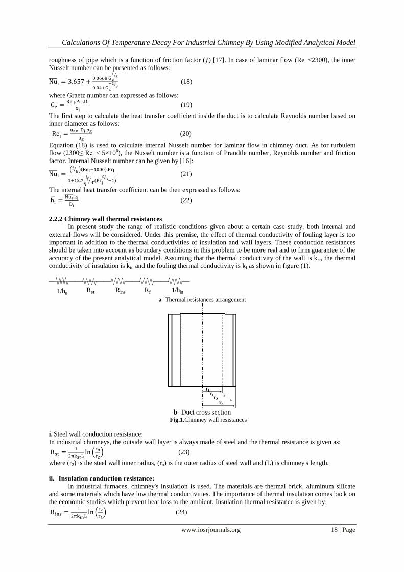
2.2.2 Chimney wall thermal resistances
In present study the range of realistic conditions given about a certain case study, both internal and
external flows will be considered. Under this premise, the effect of thermal conductivity of fouling layer is too
important in addition to the thermal conductivities of insulation and wall layers. These conduction resistances
should be taken into account as boundary conditions in this problem to be more real and to firm guarantee of the
accuracy of the present analytical model. Assuming that the thermal conductivity of the wall is kst, the thermal
conductivity of insulation is kin and the fouling thermal conductivity is kf as shown in figure (1).
1/heRst Rins Rf 1/hin
a- Thermal resistances arrangement
rir1
ro
r2
b- Duct cross section
Fig.1.Chimney wall resistances
i. Steel wall conduction resistance:
In industrial chimneys, the outside wall layer is always made of steel and the thermal resistance is given as:
(
) (23)
where (r2) is the steel wall inner radius, (ro) is the outer radius of steel wall and (L) is chimney's length.
ii. Insulation conduction resistance:
In industrial furnaces, chimney's insulation is used. The materials are thermal brick, aluminum silicate
and some materials which have low thermal conductivities. The importance of thermal insulation comes back on
the economic studies which prevent heat loss to the ambient. Insulation thermal resistance is given by:
(
) (24)
Calculations Of Temperature Decay For Industrial Chimney By Using Modified Analytical Model
www.iosrjournals.org 19 | Page
where (r1) is the inner radius of thermal insulation.
iii. Fouling conduction resistance:
After a long period of its working, most of industrial chimneys exposed to some of fly ashes which are
accumulated and deposited on chimney's inner walls. These ashes form a fouling layer. This fouling layer
increases with the time. Also, it will increase the conduction resistances. The fouling resistance can be expressed
as follows:
(
) (25)
Where (ri) is the fouling inner radius
Then the total conduction resistance is,
(26)
2.2.3 External heat transfer Coefficient
The chimney outside walls is exposed to the low ambient conditions. The present study will focus on
natural convection effect and it will take into account wind speed effect. Whenever the boundary layer thickness
is much thinner than the cylinder radius, curvature effects are negligible. The heat transfer on outside wall is
divided to heat transfer due to free convection, heat transfer due to thermal radiation and heat transfer due to
forced convection.
a- Due to free convection
The most popular correlation of free convection has been defined by Churchill and Chu [14] and can be
expressed as follows:
Nusselt number based on the height (L)
[
]
(27) *
⁄ +
⁄
(28)
(29)
Equation (29) is valid for ( ).
If , it is originally formulated and calculated as [18] and always exists and appears in tall
chimneys. Also, this is a restrictive condition for the geometry of a vertical tube, so that correction factors have
been proposed to calculate the effects of curvature of the tube [1]
( )
(30)
where ξ is transverse curvature coordinates and can be expressed as follows:
√ .
⁄
/
⁄
(31) The Nusselt number for air which includes the effect of
fluid properties and curvature is given by:
⁄
⁄
[ ] (32)
⁄
. With regarding to the computational procedures used, these correlations may be recasted into a compact and
general formula for the external Nussselt number as follows:
(
⁄ )
(33)
In our calculations the Rayleigh number (Rae,o) is based on the entrance temperature (To) is preferred than the
Rayleigh number (Rae,w) based on the wall temperature (Twe). This decision is advantageous because (Rae,o ) is a
fixed quantity and remains invariant during the cooling process.
b- Due to thermal radiation
The chimney exchanges heat through thermal radiation as a consequence of the interaction with ambient
radiation sink. The total external Nusselt number is affected with thermal radiation of ambient under calm
conditions. Just as considered mild temperature decay and a quasi isothermal wall, it is important to add
radiation effects to free convection in external Nusselt number. This can be formulated as follows [19]:
(34)

Calculations Of Temperature Decay For Industrial Chimney By Using Modified Analytical Model
www.iosrjournals.org 20 | Page
The second term of radiation in equation (34) is given by:
(35)
Where (εw) is the wall emissivity,
(σ) is the Stephan-Boltzmann constant
(Tr) is the effective radiating temperature of the surroundings which can be always considered to be equal to the
surrounding temperature (Tr ≈ T∞).
The radiation Nusselt number formula yields to be:
(36)
The calculations which are considering natural convection only leads to different temperature decay profiles. On
the other hand by adding thermal radiation to the external heat transfer coefficient this arrives to the nearest
actual profile of the temperature distribution along the chimney outside walls.
c- Due to forced convection
In some applications, wind speed should be considered. Wind is an important role in design of tall
chimney. It exerts static and dynamic loads (for tall chimney>150m height). For that, wind is essentially in
calculations of external heat transfer. Forced convection correlation made for an isothermal cylinder in cross
flow is presented by Zukauskas and Ziugzda [15].
In the range of (2×10⁵<Ree <2×10
6),
(37)
Where Ree is the Reynolds number based on the outside diameter (De) and the wind velocity (u∞). It should
be noted that the outside Nusselt number is constant in this case. For the usual range of parameters, the
contribution of forced convection due to the wind is much larger than both natural convection and thermal
radiation. For low wind velocities, however, the simultaneous contribution of the three mechanisms may be
envisaged to know the states of convection heat transfer for the outside walls. A criterion for appraising the
relative importance of convection effects for gases is given in Mills [20]. The cases of external convection can
be expressed as follows:
{
Now, there are two models that can be used to know the temperature decay along the chimney length. These
models are used to aid the designers to know the exit temperature from chimney to prevent the flue gases
condensation. The main differences between two models are as follows: in Cortes model internal Nusselt
number is a function in the internal Reynolds number and the internal Prantdle number. In the present modified
lumped model the internal Nusselt number is a function of internal Reynolds number, internal Prantdle number
and the friction factor.
The losses due to friction should be considered to improve the temperature decay along the chimney
length. Also, for the conduction resistance in the present modified model, the fouling layer is considered which
will be formed after a period of time of operation. This will improve the prediction of temperature distribution to
be more accurate than Cortes model.
III. Validation of the modified analytical model Thermal power plants which are used coal as a fuel, the combustion products contain high amounts of SO2
and other pollutants. Therefore, high stacks are needed. These chimneys are made of concrete or mineral
material. The temperature distribution along chimney was measured on coal fired power plant (Teruel Power
Station-Spain). Cortes model [1] is applied on this actual case and the results are compared with measured data
under the following conditions: T∞=18.98˚C, u∞=5m/s, To=191.678˚C, m˙= 1196.7 kg/s, Di=19.1 m, L=343 m,
kw=1.5 W/m.K.
Also, the present modified model is applied on this chimney at the same previous conditions to validate it.
The comparison between the two models and measured data are shown in figure (2).

Calculations Of Temperature Decay For Industrial Chimney By Using Modified Analytical Model
www.iosrjournals.org 21 | Page
0 100 200 300 400
Position X(m)
186
188
190
192
Ga
sT
em
pe
ratu
re(o
C)
Power Plant Chimney Of Cortes (L=343m)Present Model
Cortes Model
Cortes Exp. Data
Fig.2.Validation curve
It can be observed that the present modified model gives good results agreed well with measured data more than
Cortes model [1]. The reason of this good agreement of the present modified model with experimental results
that the present model used internal Nusselt number based on (Re,Pr,ƒ) and also, it considered the fouling
resistance resulting from deposits formed by the exhaust gases that makes a fouling layer on the inside walls of
chimney.
Fig.3.El-Araby Glass Furnace Layout
IV. Results and Discussion 4.1 Application on the present modified model
The minimum height required to obtain an adequate dispersion of pollutants is the most important design
parameter of industrial chimney. The height and structure of the stack are used to determine the exit temperature
of the flue gases and subsequently, the available static draft and the specification of fans. Condensation of water
vapor should be prevented which takes place at temperatures of about 40˚C, so the corrosion risk still persists
because the condensed water entrains dissolved sulfur compounds.
A good design should have an insulation wall in order to avoid wall cold spots in the whole firing range.
A glass melting furnace can be regarded as a chemical reactor in which raw materials like silicates, soda ash,
etc. are converted from solid state to liquid state. All glass melting reactions is done at high temperature in the
range (1450 –1500°C) in a confined space surrounded by refractory wall as shown in figure (3). This figure
shows the furnace components, the melting tank, working end and regenerator. The heat is added by using
natural gas burners. The furnace capacity is about 90 ton. A regenerator is used to preheat the combustion air.
Heat is transferred in this case by convection and radiation.
Some available data and measured parameters of El-Araby glass factory are used as another validation of the
present modified model. These data of El-Araby glass melting furnace are presented in table (1) as follows:
ـــــــــــــــــــــــــــــــــــــــــــــــــــــــــــــــــــــــــــــــــــــــــــــــــــــــ
Inner diameter Di (m) 1.30
Outer diameter (m) 1.5
Insulation thickness (m) 0.075
Deposits thickness (m) 0.015
Gas velocity at chimney exit V (m/s) 1.313
Inlet gas temperature Tb (˚C) 316
Calculations Of Temperature Decay For Industrial Chimney By Using Modified Analytical Model
www.iosrjournals.org 22 | Page
0.00%
5.00%
10.00%
15.00%
20.00%
25.00%
30.00%
35.00%
SNaKCaSiMgAlFeRbT1
Inner Reynolds number Rei 104204.5966
Gas Prandtl number Pri 0.5614
Inner Grashof number Gri up to
Stack height L (m) 45
Ambient temperature T∞ (˚C) 28
Air Prandtl number Pre 0.7
Outside wall emissivity εw 0.9
ـــــــــــــــــــــــــــــــــــــــــــــــــــــــــــــــــــــــــــــــــــــــــــــــــــــ
Table.1.El-Araby chimney data
In order to obtain accepted design of stacks, a lot of parameters should be available such as gas velocity or flow
rate and inlet temperature which are the input variables. The desired output for given ambient conditions is a
quick assessment of the average overall heat transfer coefficient and gas outlet temperature or heat losses.
The steps that should be followed during calculation of the present modified model are presented as follows:
Flue gases analysis and calculation of thermodynamic properties.
Internal Nusselt number calculation.
External Nusselt number calculation.
Thermal conduction resistances calculation.
The equivalent Nusselt number calculation.
The temperature distribution calculation.
The equivalent Nusselt number as a function of internal Nusselt number, external Nusselt number and the
thermal conductivity of wall can be presented as follows:
⁄
(38)
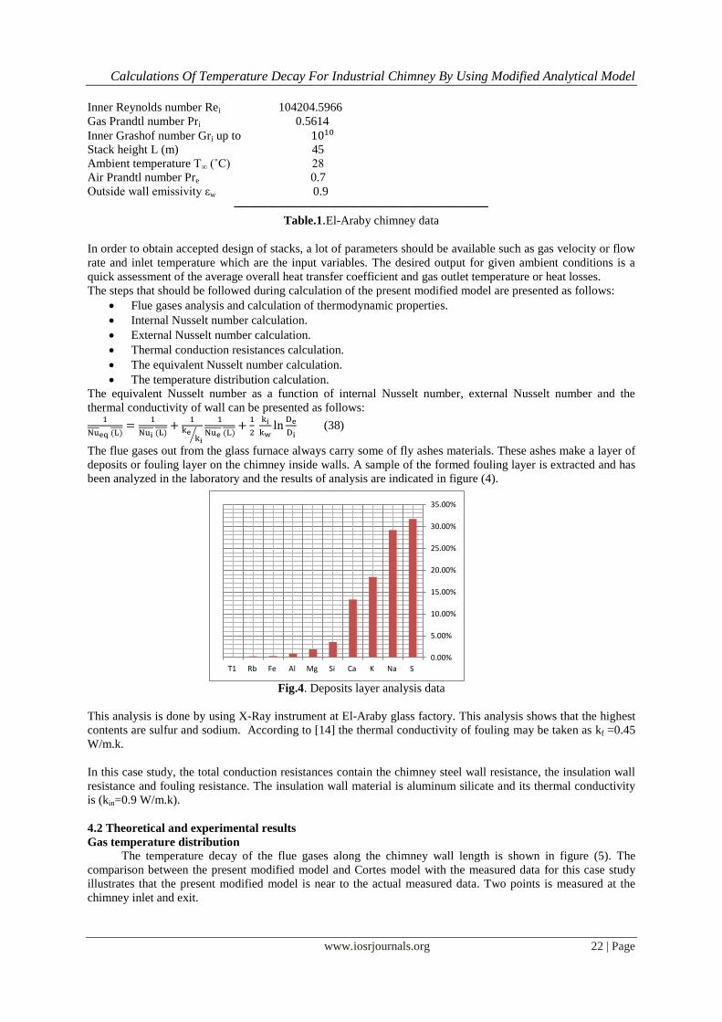
The flue gases out from the glass furnace always carry some of fly ashes materials. These ashes make a layer of
deposits or fouling layer on the chimney inside walls. A sample of the formed fouling layer is extracted and has
been analyzed in the laboratory and the results of analysis are indicated in figure (4).
Fig.4. Deposits layer analysis data
This analysis is done by using X-Ray instrument at El-Araby glass factory. This analysis shows that the highest
contents are sulfur and sodium. According to [14] the thermal conductivity of fouling may be taken as kf =0.45
W/m.k.
In this case study, the total conduction resistances contain the chimney steel wall resistance, the insulation wall
resistance and fouling resistance. The insulation wall material is aluminum silicate and its thermal conductivity
is (kin=0.9 W/m.k).
4.2 Theoretical and experimental results
Gas temperature distribution
The temperature decay of the flue gases along the chimney wall length is shown in figure (5). The
comparison between the present modified model and Cortes model with the measured data for this case study
illustrates that the present modified model is near to the actual measured data. Two points is measured at the
chimney inlet and exit.

Calculations Of Temperature Decay For Industrial Chimney By Using Modified Analytical Model
www.iosrjournals.org 23 | Page
0 10 20 30 40
Position X (m)
440
480
520
560
600
Gas
Tem
pera
ture
(K)
Glass Furnace Chimney of El-Araby
Cortes model [1]
Present Modified model
Present Expermental Data
Fig.5.Flue gas temperature distribution
Inner wall temperature distribution
The outside wall temperature is measured by using laser pyrometer instrument along the chimney outside
wall. The inner wall temperature has been calculated based on the measured values of the outside wall by
calculating heat transfer at every point. Figure (6) shows that the present modified model is approximately near
to the measured data. From this figure, it can be concluded that the present modified model can be considered as
a good analytical prediction of the temperature distribution along the inner wall of chimney.
0 10 20 30 40
Position X (m)
300
350
400
450
500
550
Inne
r Wal
l Tem
pera
ture
(K)
Glass Furnace Chimney of El-Araby
Cortes Model [1]
Present Modified Model
Present Exp. Data
Fig.6. Inner wall temperature distribution
Outside wall temperature distribution
Figure (7) shows the comparison between the measured data of outside wall and the foregoing and present
analytical works. The results indicate that the present modified model gives more adequate data and is near to
the actual measured data. The measured data are taken along the chimney outside wall at equal distances and at
the opposite side of wind direction.
0 10 20 30 40
Position X (m)
320
360
400
440
Ou
tsid
e w
all
tem
pe
ratu
re (
K)
Glass Furnace Chimney Of El-ArabyCortes model [1]
Present Modified Model
Present Exp.Data
Fig.7.Outer wall temperature distribution

Calculations Of Temperature Decay For Industrial Chimney By Using Modified Analytical Model
www.iosrjournals.org 24 | Page
V. Conclusion Chimney design of industrial furnaces is an important parameter to draught flue gases and heat to the
outside atmosphere. The engineering design of industrial chimneys requires prediction of the temperature decay
of the industrial combustion gases inside chimneys. An analytical model is developed to obtain accurate heat
transfer results.
During this study some parameters are added to Cortes model [1] to have the present modified analytical
model such as friction factor and fouling resistance that have considerable effects on both the convection and
conduction resistances. The present modified model is applied on the industrial case and it gives a good results.
The sequences of calculation are presented. A comparison between the two models and experimental
measurements carried out by the authors of this paper is done to show whichever is adequate. Finally, the
present modified model can be used by designers to quick prediction of the heat transfer characteristics of
chimneys.
Acknowledgements
The authors would like to express their thanks to El-Araby Company for Lighting Technology specially
engineers Salah and Mohammed A. El-Araby for their support to the project.
References [1] Corte's C. and Campo A., 1999," Rapid computation of the exit temperature of hot combustion gases flowing inside chimneys",
Applied thermal engineering, Vol.19, pp. 969-990. [2] Campo A. and Campo L., 1997,"An algebraic solution for a 2-D partial differential energy equation with a robin boundary condition
generated from the simpler solution for adirichlet boundary condition", Computer Math's Applications, Vol.34, pp.101-114.
[3] Marefa W., Cherkaoui H., Crausse P.and Boisson H., 2003,"Heat transfer in the turbulent flow through a conduit for removal of combustion products", Building and Environment, Vol. 38, pp. 763 – 770.
[4] Ming Chu C., Mizanur Rahman M. and Kumaresan S., 2011," Effect of cold inflow on chimney height of natural draft cooling
towers", Nuclear Engineering and Design, Vol.249, pp.125-131. [5] Joye D., 2003,"Pressure drop correlation for laminar, mixed convection, aiding flow heat transfer in a vertical tube", International
Journal of Heat and Fluid Flow, Vol.24, pp. 260-266.
[6] Kazansky S., Dubovsky V., Ziskind G.and Letan R., 2003,"Chimney-enhanced natural convection from a vertical plate: experiments and numerical simulations", International Journal of Heat and Mass Transfer, Vol. 46, pp. 497–512.
[7] Campo A., Sanchez A., 1998,"Convective heat transport of high pressure flows inside active, thick walled tubes with isothermal
outer surfaces: usage of Nusselt correlation equations for an inactive, thin walled tube", Applied Thermal Engineering, Vol.18, pp.157-169.
[8] Belver A., Iban A. and Martin C., 2012," Coupling between structural and fluid dynamic problems applied to vortex shedding in
a90 m steel chimney", J. Wind Eng. Ind. Aerodyn., Vol.100, pp.30-37. [9] Verboom G.and Koten H., 2010," Vortex excitation: Three design rules tested on13 industrial chimneys", J. Wind
Eng.Ind.Aerodyn., Vol.98, pp.145-154.
[10] Kawecki J., Zuranski J., 2007," Cross-wind vibrations of steel chimneys-A new case history", Journal of Wind Engineering and Industrial Aerodynamics, Vol. 95, pp. 1166–1175.
[11] Andreozzi A., Buonomo B. and Manca O., 2012," Numerical investigation of transient natural convection in a vertical channel-
chimney system symmetrically heated at uniform heat flux", International Journal of Heat and Mass Transfer, Article in Press [12] Bahadori A. and Vuthaluru H., 2010," Estimation of energy conservation benefits in excess air controlled gas-fired systems", Fuel
Processing Technology, Vol.91, pp. 1198–1203.
[13] Ruud G., Beerkens C.and P Hendrikus., 1992,"Modeling of the aging of glass furnace regenerators", Glastech, Vol.65, pp.247-255. [14] Churchill S.and Chu H., 1975," Correlating equations for laminar and turbulent free convection from a vertical plate", International
Journal on Heat and Mass Transfer, Vol.18, pp. 1323-1330.
[15] Zukauskas A. and Ziugzda J., 1985,"Heat Transfer of a Cylinder in Cross Flow. Hemisphere", New York. [16] Lienhard J., 2005,"Heat Transfer Text Book", Phlogiston Press.
[17] Larock B., Jeppson R., and Watters G., 2000,"Hydraulic pipe line", Boca Raton London New York Washington.
[18] Sparrow E., Gregg J., 1956," Laminar free convection heat transfer from the outer surface of a vertical circular Cylinder", ASME, Vol.78, pp.1823-1830.
[19] Incropera F., DeWitt D., 1990," Fundamentals of Heat and Mass Transfer", 3rd Ed. Wiley, New York.
[20] Mills A., 1992," Heat Transfer", Homewood.