Embed Size (px)
Citation preview

SBCA is an APPROVED SOURCE
This research report is based on practical scientific research (literature review, testing, analysis, etc.). This research report complies with the following sections of the building code:
IBC Section 104.11.1 and Section 1703.4.2 – "Research reports. Supporting data, where necessary to assist in the approval of materials or assemblies not specifically provided for in this code, shall consist of valid research reports from approved sources."
IBC Section 202 – "APPROVED SOURCE. An independent person, firm or corporation, approved by the building official, who is competent and experienced in the application of engineering principles to materials, methods or systems analyses."
Structural Building Components Association (SBCA) | 6300 Enterprise Lane, Madison, WI 53719 | 608-274-4849 | sbcindustry.com
Copyright © 2016
Calculation of a 2-Hour Fire Endurance Assembly for Metal-Plate-Connected Wood Truss Structural Floor and Roof
Framing Systems
SRR No. 1509-02
Structural Building Components Association (SBCA)
September 7, 2016

Table of Contents
Introduction: .......................................................................................................................... page 3
Assembly: .............................................................................................................................. page 4
Specifications: ...................................................................................................................... page 4
Analysis: ................................................................................................................................ page 5
Conclusion: ........................................................................................................................... page 9
Appendix A: Reports ............................................................................................................ page 10
Appendix B: UL Design No. L505 ........................................................................................ page 11
Appendix C: UL Design No. L511 ........................................................................................ page 22
Appendix D: UL Design No. L536 ........................................................................................ page 32

SBCA Research Report
SRR No. 1509-02 Calculation of a 2-Hour Fire Endurance Assembly for Metal-Plate-Connected Wood Truss Structural Floor and Roof Framing Systems Page 3 of 38 Copyright © 2016
Introduction:
There will be instances when materials and assemblies used in a building may not be readily available from prescriptive tables and tests. Theoretical methods have been developed that offer an alternative to full scale fire tests. For example, historically, Section 704.1.1 of the 1996 BOCA National Building Code, Section 703.3 of the 1994 Uniform Building Code and 701.2.1 of the 1994 Standard Building Code permit fire resistance ratings of building assemblies and structural elements to be determined in accordance with an approved analytical method.1 Current versions of the International Building Code also offer guidance regarding fire-resistance ratings in 2015 IBC Sections 703.2 and Section 703.3 as follows:
703.2 Fire-resistance ratings. The fire-resistance rating of building elements, components or assemblies shall be determined in accordance with the test procedures set forth in ASTM E119 or UL 263 or in accordance with Section 703.3. . .
703.3 Methods for determining fire resistance. The application of any of the methods listed in this section shall be based on the fire exposure and acceptance criteria specified in ASTM E119 or UL 263. The required fire resistance of a building element, component or assembly shall be permitted to be established by any of the following methods or procedures:
1. Fire-resistance designs documented in approved sources. 2. Prescriptive designs of fire-resistance-rated building elements, components or assemblies as prescribed in Section 721. 3. Calculations in accordance with Section 722. 4. Engineering analysis based on a comparison of building element, component or assemblies designs having fire-resistance
ratings as determined by the test procedures set forth in ASTM E119 or UL 263. 5. Alternative protection methods as allowed by Section 104.11. 6. Fire-resistance designs certified by an approved agency.
The analysis in this research report used the method listed in IBC Section 703.3, method number 4, Engineering analysis. Note, the calculation in accordance with Section 722 (#3) for wood are limited to a maximum of 1 hour (Section 722.6.1.1), however, that limitation does not apply to method 4. Also note that Section 721 (#2) Table 721.1(3), item 28-1.1, includes a prescriptive ceiling design using I-joists2, 3 layers of 5/8” Type C gypsum and 7/8” furring channel with a 2 hour rating. One theoretical method known as the “Ten Rules of Fire Endurance Ratings” was published by T.Z. Harmathy in the May, 1965 edition of Fire Technology2. Harmathy’s Rules provided a foundation for extending fire endurance assembly data and are used extensively in this report. Fire endurance assembly calculations are also delineated in Fire Safety Design in Buildings, by the Canadian Wood Council; Component Additive Method for Calculating and Demonstrating Assembly Fire Endurance, by the American Wood Council (AWC), and Chapter 7 of BOCA’s Guidelines for Determining Fire Resistance Ratings of Building Elements. Additionally, the UL Fire Resistance Directory, Design Number L536 assembly is a calculated assembly and was developed in conjunction with the component additive method (CAM) principles. UL Design L536 was authored by the primary author of this report, Mr. Kirk Grundahl, and Mr. Dan Swytnyk of UL. The calculations in this report are based on CAM principles for metal plate connected wood truss construction using engineering analysis based on comparisons to tested assemblies in accordance with method #4 on behalf of the Structural Building Components Association.
1 Adapted from “Guidelines for determining Fire Resistance Ratings of Building Elements”, BOCA, International, 1994, pg. 52, section 7.2.3 2 See AWC DCA-3 assembly WIJ-2.1 2 T.Z. Harmathy, “Ten Rules of Fire Endurance Rating,” Fire Technology, 1(2), May, 1965, 102pp. 93-102.

SBCA Research Report
SRR No. 1509-02 Calculation of a 2-Hour Fire Endurance Assembly for Metal-Plate-Connected Wood Truss Structural Floor and Roof Framing Systems Page 4 of 38 Copyright © 2016
Assembly:
Specifications:
Fire Rating: Two hours Finish Rating: More than 90 minutes
1. Finish flooring: 5/8"-thick or thicker sheets of interior plywood or oriented strand board (OSB), manufactured with exterior glue having tongue-and-groove edges along the 8' side of 4'x8' sheets, shall be installed perpendicular to the trusses with end joints centered over the top chord of the truss, and placed so the end joints are staggered. The application of the plywood or OSB shall comply with the specifications and recommendations provided by the American Plywood Association.
A lightweight concrete topping may be (but does not have to be) applied over the plywood or OSB. Generally, this topping should be 3/4"-thick or thicker, following the architectural specifications and topping manufacturer’s guidelines.
2. Structural members: A minimum 12"-deep metal plate connected wood truss spaced at a maximum of 24" o.c. can be used in this assembly. The truss application should follow the installation recommendations developed by the Structural Building Components Association (SBCA).
3. Ceiling Membrane: Three layers of Type C gypsum wallboard are used in this assembly. Each sheet used is assumed to be a minimum of 4' wide. The gypsum wallboard attached directly to the trusses should be placed perpendicular to the trusses. The gypsum wallboard attached to the furring channels is assumed to be installed perpendicular to the furring channels. The ceiling is created as follows:
a. Wallboard Layer 1: The first 5/8" layer of gypsum wallboard is attached directly to the bottom chord of the truss using 1-1/4" Type S bugle-head screws spaced 6" o.c. along wallboard ends and edges, and 12" o.c. in the field. The application of the Type C gypsum wallboard shall follow the manufacturer’s installation instructions. The wallboard end joints should be centered on the bottom chord of the trusses, and should be staggered. The minimum end distance (minimum distance the screws are to be held back from 4' end of wallboard, i.e., butt end) allowed for the base layer is 3/8". The minimum edge distance (minimum distance the screws are to be held back from 8', 10', etc., side of wallboard) is 1-1/2".
b. Furring Channel: Resilient or inverted hat-type furring channels are placed over the top of the first layer of 5/8" Type C gypsum wallboard. The channels are made of 25-gauge galvanized steel, and installed perpendicular to the structural members. The channels are spaced at a maximum of 24" o.c., and attached to each truss (through the gypsum) with one 1-7/8" Type S screw.
c. Wallboard Layer 2: This layer of 5/8" Type C gypsum wallboard is attached to the furring or resilient channels. Layer 2 is attached with 1 or 1-1/4" Type S bugle-head screws spaced at a maximum of 6" o.c. The end joints of each gypsum wallboard sheet shall be centered on the resilient or furring channel. End distance shall be a minimum of 5/8". Edge distance shall be a minimum of 1-1/2".
d. Wallboard Layer 3: The finish layer of 5/8" Type C gypsum wallboard shall be attached to each resilient or furring channel with a 1-5/8 or 1-7/8" Type S bugle-head screw that passes through wallboard layer 2. The screws shall be
SBCA Research Report
SRR No. 1509-02 Calculation of a 2-Hour Fire Endurance Assembly for Metal-Plate-Connected Wood Truss Structural Floor and Roof Framing Systems Page 5 of 38 Copyright © 2016
spaced at a maximum of 6" o.c. End distance shall be a minimum of 5/8". Edge distance shall be a minimum of 1-1/2". The end and edge joints of the finish layer of gypsum should be staggered at a minimum of 24" from the joints that exist in layer 2. The end joints of the face layer must be centered on the furring channels. If this is not the case, end joints shall be attached to Wallboard Layer 2 with 1-1/2" Type G screws spaced 6" o.c. with an end and edge distance of 1-1/2".
All screws shall be set so that they are flush with the face of the wallboard and do not damage the core of the wallboard.
The following gypsum wallboard3 may be used in this assembly:
• American Gypsum Co., LLC: Type AG-C • CertainTeed Gypsum, Inc.: Type C • CGC Inc.: Types C, IP-X2, IBP-AR • Continental Building Products Operating Co.: Type LGFC-C/A • Georgia-Pacific Corp., Gypsum Division: Types 5, DAPC, TG-C • National Gypsum Co.: Types FSK-C, FSMR-C, FSW-C • Pabco Gypsum Co.: Type C • Temple-Inland Forest Products Corp.: Type TG-C • United States Gypsum: Types C, IP-XZ, IPC-AR
4. Wallboard Screws: Type S bugle head screws that are self-drilling and self-tapping shall be used. Where needed, Type G wallboard screws can also be used. Screws shall meet ASTM C1002 or ASTM C954 standards.
5. Finishing Systems (Not Shown): The face layer joints shall be covered with tape and coated with joint compound. Screws shall also be covered with joint compound.
Analysis:
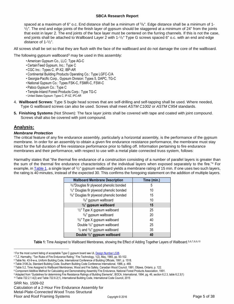
Membrane Protection The critical feature of any fire endurance assembly, particularly a horizontal assembly, is the performance of the gypsum membrane. In order for an assembly to obtain a given fire endurance resistance performance, the membrane must stay intact for the full duration of fire resistance performance prior to falling off. Information pertaining to fire endurance membranes and their performance, with respect to use with a metal plate connected truss system, follows: Harmathy states that “the thermal fire endurance of a construction consisting of a number of parallel layers is greater than the sum of the thermal fire endurance characteristics of the individual layers when exposed separately to the fire.”4 For example, in Table 1, a single layer of 1/2" gypsum wallboard yields a membrane rating of 15 min. If one uses two such layers, the rating is 40 minutes, instead of the expected 30. This confirms the foregoing statement on the addition of multiple layers.
Wallboard Membrane Description Time (min.) 3/8"Douglas fir plywood phenolic bonded 5 1/2" Douglas fir plywood phenolic bonded 10 5/8" Douglas fir plywood phenolic bonded 15
3/8" gypsum wallboard 10 1/2" gypsum wallboard 15
1/2" Type X gypsum wallboard 25 5/8" gypsum wallboard 20
5/8" Type X gypsum wallboard 40
Double 3/8" gypsum wallboard 25 1/2 and 3/8" gypsum wallboard 35
Double 1/2" gypsum wallboard 40
Table 1: Time Assigned to Wallboard Membranes, showing the Effect of Adding Together Layers of Wallboard.5,6,7,8,9,10
3 For the most current listing of acceptable Type C gypsum board see UL Design Number L538. 4 T.Z. Harmathy, “Ten Rules of Fire Endurance Rating,” Fire Technology, 1(2), May, 1965, pp. 93-102. 5 Table No. 43-9-w-a, Uniform Building Code, International Conference of Building Officials, 1991, p. 1518. 6 Table 3106.2a, Standard Building Code, Southern Building Code Conference International, 1988, p. 469. 7 Table 5.2, Time Assigned to Wallboard Membranes, Wood and Fire Safety, Canadian Wood Council, 1991, Ottawa, Ontario, p. 122. 8 Component Additive Method for Calculating and Demonstrating Assembly Fire Endurance, National Forest Products Association, 1991. 9 Adapted from “Guidelines for determining Fire Resistance Ratings of Building Elements”, BOCA, International, 1994, pg. 46, section 6.2.3, table 6.2.3(1) 10 Table 722.2.1.4(2) and Table 722.6.2(1), International Building Code, International Code Council, 2015

SBCA Research Report
SRR No. 1509-02 Calculation of a 2-Hour Fire Endurance Assembly for Metal-Plate-Connected Wood Truss Structural Floor and Roof Framing Systems Page 6 of 38 Copyright © 2016
Associated with the above additive rule for fire endurance assemblies, another rule states that the fire endurance of a construction does not decrease with the addition of additional layers.11 The validity of this rule follows from the fact that by adding layers of material, both the resistance to heat flow and heat capacity of the construction increase. This, in turn, reduces the rate of temperature rise in the plenum and, therefore, at the unexposed surface. For this to work, however, certain restrictions must apply. The added layer must have similar thermal expansion characteristics to that of the adjacent layer. The added layer must also have similar thermal transmission properties, and be a material that is inherently thermal resistant like gypsum board. In other words, adding a layer of steel to the unexposed surface would not enhance the fire performance of the assembly, whereas adding a plaster layer would. The following analysis shows a protective membrane of 120 min. using the CAM:
Wallboard Membrane Description Time (min.) 5/8" Type X gypsum wallboard 40 5/8" Type X gypsum wallboard 40 5/8" Type X gypsum wallboard 40
Total 120
Table 2: Combined Wallboard Membrane Time Calculation
This amount of membrane protection yields the 2-hour rating desired. It is known that the direct addition of membrane times is conservative, based on the rules given above and shown by the 1/2" gypsum wallboard example in Table 1. Additionally, Type C gypsum is specified in the assembly since it has better fire endurance performance than Type X.12 Assembly Fire Endurance Performance Enhancements In order to be more conservative in this calculated assembly, enhancements have been added to provide greater assurance that this assembly will meet the 2-hour rating. The description of these enhancements follow:
Harmathy states that the fire endurance of constructions containing continuous air gaps or cavities is greater than the fire endurance of similar constructions of the same weight, but containing no air gaps or cavities.13 The validity of this rule rests on the fact that the insertion of voids produces an additional resistance to the path of heat flow, much like a storm window.
As seen in the assembly described above, resilient channels have been inserted between Wallboard Layer 1 of the assembly and the two layers below it. This serves the following functions:
It creates a continuous air space that will enhance the fire performance of the membrane system and creates
dead air space that is insulating.
Attaching the resilient channel over the first layer of gypsum provides additional support for, and therefore
enhances the stability of, the first layer of gypsum wallboard. This will aid in keeping this layer of gypsum in
place, resulting in better assembly fire performance.
There will be two connection points of the first layer into the truss system. The first will be attaching the gypsum
layer to the truss, and the second will be attaching the resilient channel through the first gypsum layer into the
truss. As noted above, these additional connections will enhance the stability of the membrane attachment, and
thus keep layer 1 on longer and improve the overall fire performance of the assembly.
In the analysis performed for the National Fire Protection Research Foundation (NFPRF), entitled, National Engineered Lightweight Construction Fire Research Project, two assemblies were analyzed that showed the effects of the addition of resilient channels.14 The Factory Mutual reports, Design FC-240 and Design FC-235 indicate an additional 6 minutes of performance due to the addition of resilient channels. See a summary of these reports in Appendix A.
11 Harmathy, loc. cit. 12 Type X board has glass fibers in the core for enhanced fire performance and is tested in specific fire-rated assemblies. Type C meets all the requirements of the Type X board and is further enhanced with additional glass fibers and other core ingredients for an even greater level of fire performance. Type C core ingredients are proprietary. If the design calls for a Type C board, a Type X board cannot be used as a substitute. See the gypsum products listed in the assembly. 13 Harmathy, loc. cit. 14 Grundahl, Kirk, P.E., National Engineered Lightweight Construction Fire Research Project, Phase I: Literature Search and Technical Analysis, National Fire Protection Research Foundation, October, 1992.

SBCA Research Report
SRR No. 1509-02 Calculation of a 2-Hour Fire Endurance Assembly for Metal-Plate-Connected Wood Truss Structural Floor and Roof Framing Systems Page 7 of 38 Copyright © 2016
For the assembly described above, the following calculation could then be made:
Description Time (min.)
3 layers of 5/8" Type X gypsum wallboard 120
Resilient channels spaced to a maximum of 16" o.c. 6
Total 126
Table 3: Revised Calculation Adding Resilient Channels
Note that there has still been no credit given for the multiple layer effect. This membrane could be calculated as at least a 136-minute assembly by adding the 10-minute performance increase, using the 2 layers of 1/2" gypsum example shown earlier.
Description Time (min.)
3 layers of 5/8" Type X gypsum wallboard 120
Resilient channels spaced to a maximum of 16" o.c. Credit for Multiple Layers of Gypsum
6 10
Total 136
Table 4: Revised Calculation Adding Resilient Channels and Multiple Gypsum Layer Effect
Engineering Evaluation from ASTM E119 Tests To evaluate the reliability and reasonability of this assembly, currently performed and publicly reported ASTM E119 testing can be reviewed as a generally accepted industry standard and methodology. This method presents the confidence needed to recommend that this proposed fire endurance assembly will provide 2-hour fire endurance protection. Justification based on ASTM E119 testing follows:
There are three examples of assemblies that utilize 2 layers of 5/8" Type C gypsum wallboard: UL L505, L511 and L536 (see 2015 summaries of each test in Appendix B, Appendix C & Appendix D respectively). The finish rating is 75, 71 and 71 minutes, respectively. In these assemblies, the resilient channel was spaced 24" o.c., and the wallboard was attached with 8d nails spaced 7" o.c. These tests illustrate the endurance performance of the wallboard, and provide the time it took for this membrane and connection system to provide thermal protection of the assembly to 250° F plus ambient on average, or 325°F, plus ambient at a single point.
There are two metal plate connected truss tests available that provides an indication of single gypsum layer performance with trusses spaced at 24" o.c. Factory Mutual FC-235 (Appendix A) shows 5/8" USG Type C board provides a 24-minute finish rating and PFS 88-0315 shows 5/8" USG Type C board provides a 23-minute finish rating16. Performing a combined finish rating calculation yields:
Description Time (min.)
Single layer of 5/8" Type C wallboard attached to Trusses Resilient channels
Single layer of 5/8" Type C wallboard attached to resilient channels 71-75
Single layer of 5/8" Type X or Type C 23-24
Finish rating range of performance 94-99
Table 5: Combined Finish Rating Performance
This range is conservative given the additive rule described above, where the addition of material adds more fire resistance than the pure sum of fire resistance.
This analysis shows the time it takes the back side of the wallboard to reach an average of 250°F above the ambient temperature (approximately 250 + 70 = 320°), which is well below the temperature that wood begins to char (482°F).
The performance of the trusses in the fire test assemblies FC-235 and PFS 88-03 after the finish rating was reached was 26 and 29 minutes, respectively.
15 PFS 88-03 is referenced in NER-392 as one of the documents submitted for evidence. 16 Grundahl, Kirk, P.E., National Engineered Lightweight Construction Fire Research Project, Phase I: Literature Search and Technical Analysis, National Fire Protection Research
Foundation, October, 1992. Table 4-2.11 pg. 123

SBCA Research Report
SRR No. 1509-02 Calculation of a 2-Hour Fire Endurance Assembly for Metal-Plate-Connected Wood Truss Structural Floor and Roof Framing Systems Page 8 of 38 Copyright © 2016
By adding these values to the finish rating range of performance above:
Description Time (min.)
Finish Rating Range of Performance 94-99
Truss Performance after Finish rating is achieved 26-29
Assembly Performance Range 120 – 128
Table 6: Finish Rating Performance with Truss Performance
Therefore, the ASTM E119 testing justifies the previous fire endurance performance calculations, shown in Table 2, Table 3 and Table 4. The beneficial effect of adding layers of wallboard together has still not been included in the analysis. This effect should add a minimum of 10 minutes to the performance for a range of 130 - 138 minutes, which is in excess of the 2-Hour rating desired.
Description Time (min.)
Finish Rating Range of Performance 94-99
Truss Performance after Finish rating is achieved Beneficial Effect of Adding Gypsum Layers Together
26-29 10
Assembly Performance Range 130 – 138
Table 7: Assembly Performance Rating with Gypsum Added Connection System In order for the membrane system to adequately or suitably protect the trusses from the impact of fire, the connection detailing becomes extremely important. The connections must hold the gypsum membrane in place during the exposure time and have enough withdrawal resistance to hold the dead load of the gypsum wallboard. The calculations for the screwing patterns as described above follow:
Since the trusses are spaced 24" o.c. and the base layer screw spacing is 6" o.c., each screw must hold 1 ft.2 of
gypsum weight. Type C gypsum weighs approximately 2.5 lbs. per ft.2, so each screw must hold 2.5 lbs. of dead
weight. Assuming the typical 1-1/4" Type S, 6 gauge screws are being used with wood that has a specific gravity assumed to be 0.42 or greater, which covers Spruce-Pine-Fir chord stock, a screw withdrawal resistance of 69 lbs./in. of length. This is based on the 2015 National Design Specification for Wood Construction17. Since attaching 5/8" thick gypsum with a 1-1/4" screw, the shank length of the screw going into the wood is 5/8". Therefore, the screw holding power for each base layer screw is 43.125 lbs. This is much greater than the 2.5 lbs. required. (Using Southern Pine or Douglas Fir Larch for chords, 0.50 specific gravity, results in a value of 61.25 lbs. per screw.)
Since the resilient channels are spaced 24" o.c., and the joists are spaced 24" o.c., the screws attaching the
resilient channel to the wood joist must hold four square feet of gypsum times two layers of gypsum times 2.5 lbs./ft.2 for each 5/8" Type C gypsum layer. This is a total of 20 lbs. of load per screw. Using a 1-7/8" Type S screw that penetrates a 5/8" thick layer of gypsum and the resilient furring channel leaves approximately 1-1/4" of penetration. Using a withdrawal design value of 69 lbs./in. of penetration yields a capacity for each screw holding the resilient channel to the joist of 86.25lbs. This is far in excess of the 20 lbs. required.
The middle layer of the wallboard should be attached to each furring or resilient channel with 1 or 1-1/4" Type S screws spaced 6" o.c. These screws must each carry 1.0 ft.2 of load, with Type C gypsum weighing 2.5 lbs./ft.2,
requiring a screw load capacity of 2.5 lbs. The calculated pull-out (withdrawal)18 resistance of a #6 Type S screw penetrating 25-gauge, 33 ksi, steel resilient channels exceeds 60 lbs., which far exceeds the 2.5 lbs. required.
A face layer of the wallboard shall be attached to each furring or resilient channel through the middle layer wallboard with 1-5/8 or 1-7/8" Type S screws. These screws shall be spaced at a maximum of 6" o.c. These screws also have a load applied to them of 2.5 lbs. Therefore, the withdrawal resistance of 60 lbs. per screw in resilient channels is more than sufficient to carry the load.
17 National Design Specification for Wood Construction, AWC, 2015, p. 78. 18 AISI S100-2012, Eq. E4.4.1-1

SBCA Research Report
SRR No. 1509-02 Calculation of a 2-Hour Fire Endurance Assembly for Metal-Plate-Connected Wood Truss Structural Floor and Roof Framing Systems Page 9 of 38 Copyright © 2016
Assembly Modifications Depth/Spacing: The trusses in this design have a minimum depth of 12". Trusses with depths greater than 12" may be used. Dimensions included for depth of assemblies are minimums, spacings are maximums. GA-600 includes the following statement under General Explanatory Notes, item 17 & 20:
17. Specified floor-ceiling and roof-ceiling framing sizes or truss dimensions are minimums. Greater joist or truss sizes (depths) shall be permitted to be used in metal- or wood-framed systems. Indicated joist and truss spacings are maximums.
20. Floor-ceiling and roof-ceiling systems were fire tested at less than 36 inches total depth. However, the total depth of the systems, with either directly attached or suspended ceiling membranes, shall be permitted to extend greater than 36 inches.
Insulation: Both UL and GA include specific guidance regarding the use of insulation in assemblies. G500, L500, M500, and P500 series designs listed by UL BXUV allow addition of any depth of insulation at any location in an assembly that does not include insulation, but only as long as another layer of gypsum (of the same type as specified in the tested assembly) is installed at the ceiling. Any other method of adding insulation is prohibited in assemblies tested without insulation. A similar general provision is included in GA-600. However, IBC 703.3, items 4 or 5 do allow modifications to assemblies, including inclusion or placement of insulation, based on rational design provided to the building official.
In deeper trusses, the space above the 12" plenum depth may contain insulation, provided the insulation is supported adequately so that the plenum depth is maintained at 12" from the backside of the gypsum due to the conservative design methodology.
Conclusion:
This assembly has been developed using engineering analysis based on a comparison to assemblies having fire-resistance ratings as determined by the test procedures set forth in ASTM E119 or UL 263 and is shown to achieve a 2-hour fire endurance performance rating, based both on the CAM and as verified by comparison to existing ASTM E119 tests. The development of this assembly was deliberately conservative to ensure 2-hour performance in the following ways:
• Type C gypsum wallboard is specified instead of Type X as given in Table 1. This wallboard has proven to be a more stable wallboard, and thus will more adequately protect the truss assembly.
• By placing the resilient channels over the top of wallboard layer 1, the channels will hold the wallboard in place and enhance the performance of the fire endurance assembly. This is due to the increased likelihood the wallboard will not fall away from the trusses prematurely.
• The Type S gypsum wallboard screws are spaced at 6" o.c. to provide good connection support of the wallboard membrane. The loads carried by each fastener has also been considered to ensure that there is a large margin of reserve capacity for each screw. The key to an assembly's performance is an intact membrane. This fastener schedule seeks to ensure the membrane will stay intact and perform as expected.
Given the above, the described assembly will confidently afford a 2-hour fire endurance performance as required by the building code.

SBCA Research Report
SRR No. 1509-02 Calculation of a 2-Hour Fire Endurance Assembly for Metal-Plate-Connected Wood Truss Structural Floor and Roof Framing Systems Page 10 of 38 Copyright © 2016
Appendix A: Reports
Report: Floor/Ceiling Wood Truss Assembly Design FC-235
Author: W.R. Price and W.F. Shield, Factory Mutual Research
Sponsor: Truss Plate Institute
Date: August 6, 1976
Basic Test Description: The floor assembly consisted of floor trusses, 12 in. deep with nominal 2 x 4 wood chords and
webs. The floor trusses were 17 ft., 5 in. long, and were spaced 24 in. on center. The floor was a single layer of 3/4 in. thick
plywood with vinyl asbestos tile attached to it. The ceiling was a single layer of 5/8 in. Type FSW (or Type C) gypsum
wallboard, produced by National Gypsum Company, and was secured directly to the bottom chords of the trusses.
Test Method Used: ASTM E119.
Report Observations: Observations were made of the exposed and unexposed surface, deflection measurements of the
floor were made, and the temperature of the unexposed surface, plenum and furnace were measured.
Report Summary: The assembly was subjected to a uniformly distributed live load of 50.1 psf, which resulted in a combined
live and dead load of 57.4 psf. The deflection at the center of the assembly at 50 min. was 3.5 in. There were no unusual
occurrences based on the observations made for both the unexposed and exposed surfaces during the test. The test was
terminated at 50 min. when the assembly failed to support the superimposed load. The finish rating was calculated to be 24
min.
Comments: THIS TEST GIVES AN INDICATION OF THE PERFORMANCE OF METAL PLATE CONNECTED WOOD TRUSSES WITH
SINGLE LAYER GYPSUM PROTECTION. THE GYPSUM BOARD USED WAS IDENTICAL TO THAT USED IN THE I-JOIST TEST ABOVE.
Report: Floor/Ceiling Truss Assembly Design FC-240
Authors: W.R. Price and W.F. Shield, Factory Mutual Research
Sponsor: Truss Plate Institute
Date: April 13, 1977
Basic Test Description: The floor assembly consisted of floor trusses 12 in. deep with nominal 2 x 4 wood chords and
webs, and were 17 ft., 5 in. long. Trusses were spaced 24 in. on center. The floor was a single layer of 3/4 in. thick
tongue-and-groove plywood. The ceiling was a single layer of 5/8 in. thick Firecode C gypsum wallboard manufactured by
USG secured to furring channels attached to the bottom chords of the trusses. The furring channels, manufactured by
USG and designated as RC-1 resilient channels, were installed perpendicular to the trusses, and located 16 in. on center.
Test Method Used: ASTM E119.
Report Observations: Observations of the exposed and unexposed surfaces were made, and the deflection of the floor,
the temperature of the furnace, plenum, and unexposed surface, and time of failure of the assembly were recorded.
Report Summary: The assembly was subjected to a uniformly distributed live load of 50.7 psf, which resulted in a
combined live and dead load of 57.8 psf. There were no unusual observations of either the exposed or unexposed
surfaces during the test. The maximum deflection of the floor occurred at 58 min., where the center-most deflection was
2.13 in. The test was terminated at 58 min., when the assembly failed to support the superimposed load. The finish rating
was calculated to be 26 min.
Comments: THIS TEST HIGHLIGHTS THE EFFECTS OF RESILIENT CHANNELS ON TRUSSES WITH ALL OTHER FACTORS BEING
EQUAL. IN THIS CASE, THE RESILIENT CHANNEL ADDED APPROXIMATELY 6 MIN. TO THE PERFORMANCE OF THE ASSEMBLY,
CALCULATED AS FOLLOWS:
(58-26)-50-24) = 6 MIN.
This calculation accounts only for performance after the finish rating was met for the membrane, and is certainly not
absolute for all cases. It only provides an indication.

SBCA Research Report
SRR No. 1509-02 Calculation of a 2-Hour Fire Endurance Assembly for Metal-Plate-Connected Wood Truss Structural Floor and Roof Framing Systems Page 11 of 38 Copyright © 2016
Appendix B: UL Design No. L505

SBCA Research Report
SRR No. 1509-02 Calculation of a 2-Hour Fire Endurance Assembly for Metal-Plate-Connected Wood Truss Structural Floor and Roof Framing Systems Page 12 of 38 Copyright © 2016

SBCA Research Report
SRR No. 1509-02 Calculation of a 2-Hour Fire Endurance Assembly for Metal-Plate-Connected Wood Truss Structural Floor and Roof Framing Systems Page 13 of 38 Copyright © 2016

SBCA Research Report
SRR No. 1509-02 Calculation of a 2-Hour Fire Endurance Assembly for Metal-Plate-Connected Wood Truss Structural Floor and Roof Framing Systems Page 14 of 38 Copyright © 2016

SBCA Research Report
SRR No. 1509-02 Calculation of a 2-Hour Fire Endurance Assembly for Metal-Plate-Connected Wood Truss Structural Floor and Roof Framing Systems Page 15 of 38 Copyright © 2016

SBCA Research Report
SRR No. 1509-02 Calculation of a 2-Hour Fire Endurance Assembly for Metal-Plate-Connected Wood Truss Structural Floor and Roof Framing Systems Page 16 of 38 Copyright © 2016

SBCA Research Report
SRR No. 1509-02 Calculation of a 2-Hour Fire Endurance Assembly for Metal-Plate-Connected Wood Truss Structural Floor and Roof Framing Systems Page 17 of 38 Copyright © 2016

SBCA Research Report
SRR No. 1509-02 Calculation of a 2-Hour Fire Endurance Assembly for Metal-Plate-Connected Wood Truss Structural Floor and Roof Framing Systems Page 18 of 38 Copyright © 2016
SBCA Research Report
SRR No. 1509-02 Calculation of a 2-Hour Fire Endurance Assembly for Metal-Plate-Connected Wood Truss Structural Floor and Roof Framing Systems Page 19 of 38 Copyright © 2016

SBCA Research Report
SRR No. 1509-02 Calculation of a 2-Hour Fire Endurance Assembly for Metal-Plate-Connected Wood Truss Structural Floor and Roof Framing Systems Page 20 of 38 Copyright © 2016

SBCA Research Report
SRR No. 1509-02 Calculation of a 2-Hour Fire Endurance Assembly for Metal-Plate-Connected Wood Truss Structural Floor and Roof Framing Systems Page 21 of 38 Copyright © 2016

SBCA Research Report
SRR No. 1509-02 Calculation of a 2-Hour Fire Endurance Assembly for Metal-Plate-Connected Wood Truss Structural Floor and Roof Framing Systems Page 22 of 38 Copyright © 2016
Appendix C: UL Design No. L511

SBCA Research Report
SRR No. 1509-02 Calculation of a 2-Hour Fire Endurance Assembly for Metal-Plate-Connected Wood Truss Structural Floor and Roof Framing Systems Page 23 of 38 Copyright © 2016

SBCA Research Report
SRR No. 1509-02 Calculation of a 2-Hour Fire Endurance Assembly for Metal-Plate-Connected Wood Truss Structural Floor and Roof Framing Systems Page 24 of 38 Copyright © 2016
SBCA Research Report
SRR No. 1509-02 Calculation of a 2-Hour Fire Endurance Assembly for Metal-Plate-Connected Wood Truss Structural Floor and Roof Framing Systems Page 25 of 38 Copyright © 2016

SBCA Research Report
SRR No. 1509-02 Calculation of a 2-Hour Fire Endurance Assembly for Metal-Plate-Connected Wood Truss Structural Floor and Roof Framing Systems Page 26 of 38 Copyright © 2016

SBCA Research Report
SRR No. 1509-02 Calculation of a 2-Hour Fire Endurance Assembly for Metal-Plate-Connected Wood Truss Structural Floor and Roof Framing Systems Page 27 of 38 Copyright © 2016

SBCA Research Report
SRR No. 1509-02 Calculation of a 2-Hour Fire Endurance Assembly for Metal-Plate-Connected Wood Truss Structural Floor and Roof Framing Systems Page 28 of 38 Copyright © 2016

SBCA Research Report
SRR No. 1509-02 Calculation of a 2-Hour Fire Endurance Assembly for Metal-Plate-Connected Wood Truss Structural Floor and Roof Framing Systems Page 29 of 38 Copyright © 2016

SBCA Research Report
SRR No. 1509-02 Calculation of a 2-Hour Fire Endurance Assembly for Metal-Plate-Connected Wood Truss Structural Floor and Roof Framing Systems Page 30 of 38 Copyright © 2016

SBCA Research Report
SRR No. 1509-02 Calculation of a 2-Hour Fire Endurance Assembly for Metal-Plate-Connected Wood Truss Structural Floor and Roof Framing Systems Page 31 of 38 Copyright © 2016

SBCA Research Report
SRR No. 1509-02 Calculation of a 2-Hour Fire Endurance Assembly for Metal-Plate-Connected Wood Truss Structural Floor and Roof Framing Systems Page 32 of 38 Copyright © 2016
Appendix D: UL Design No. L536

SBCA Research Report
SRR No. 1509-02 Calculation of a 2-Hour Fire Endurance Assembly for Metal-Plate-Connected Wood Truss Structural Floor and Roof Framing Systems Page 33 of 38 Copyright © 2016
SBCA Research Report
SRR No. 1509-02 Calculation of a 2-Hour Fire Endurance Assembly for Metal-Plate-Connected Wood Truss Structural Floor and Roof Framing Systems Page 34 of 38 Copyright © 2016

SBCA Research Report
SRR No. 1509-02 Calculation of a 2-Hour Fire Endurance Assembly for Metal-Plate-Connected Wood Truss Structural Floor and Roof Framing Systems Page 35 of 38 Copyright © 2016

SBCA Research Report
SRR No. 1509-02 Calculation of a 2-Hour Fire Endurance Assembly for Metal-Plate-Connected Wood Truss Structural Floor and Roof Framing Systems Page 36 of 38 Copyright © 2016

SBCA Research Report
SRR No. 1509-02 Calculation of a 2-Hour Fire Endurance Assembly for Metal-Plate-Connected Wood Truss Structural Floor and Roof Framing Systems Page 37 of 38 Copyright © 2016

SBCA Research Report
SRR No. 1509-02 Calculation of a 2-Hour Fire Endurance Assembly for Metal-Plate-Connected Wood Truss Structural Floor and Roof Framing Systems Page 38 of 38 Copyright © 2016