Embed Size (px)
Citation preview
N
CAL NOTE 235
A XUMERICAL APPROACH TO THE INSTABILITY
PROBLEM O F MONOCOQUE CYLINDERS
By Bruno A. Boley, Joseph Kempner and J. Mayer s
Polytechnic Institute of Brooklyn
Washington Apr i l 1951
NATIONAL ADVISORY COMMITTEE FOR AERONAUTICS
TECHNICAL NOTE 2354 ,
A NUMERICAL APPROACH TO THE INSTABILITY
PROBLEM OF MONOCOQUE CYLINDERS
By Bruno A. Boley, Joseph Kempner and J. Mayers
/
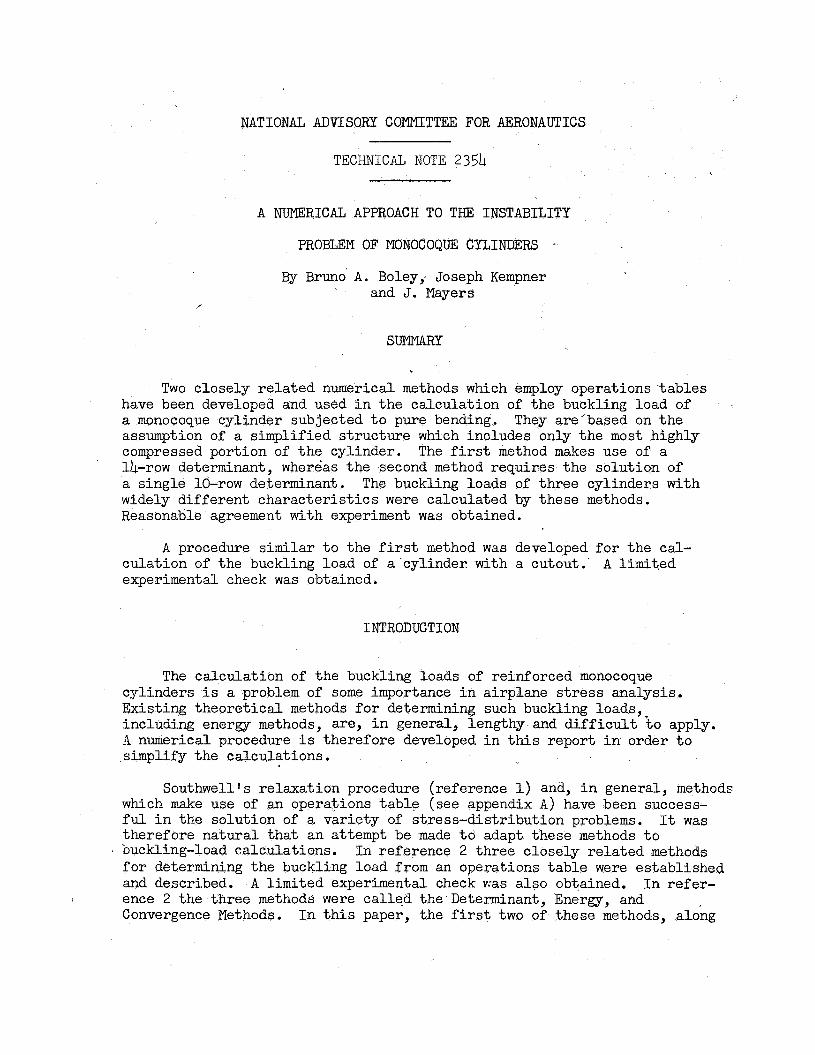
SUMMARY
Two closely re la ted numerical methods which employ operations ‘tables have been developed and used i n the calculation of the buckling load of a monocoque cylinder subjected t o pure bending. assumption of a simplified s t ructure which includes only the most highly compressed portion of the cylinder. 14-row determinant, whereas the second method requires the solution of a single 10-row determinant. widely different charac te r i s t ics were calculated by these methods. Reasonable agreement with experiment was obtained.
They are’based on the
The f irst method makes use of a
The buckling loads of three cylinders with
A procedure similar t o the f irst method was developed f o r the cal- culation of the buckling load of a cylinder with a cutout. experimental check was obtained.
A l imited
INTRODUCTION
The calculation of the buckling loads of reinforced monocoque cylinders i s a problem of some importance i n airplane s t r e s s analysis. Existing theoret ical methods f o r determining such buckling loads, including ener&y methods, are, i n general, lengthy and d i f f i c u l t t o apply. I numerical procedure i s therefore developed i n t h i s report i n order t o simplify the calculations.
Southwell’s relaxation procedure (reference 1) and, i n general, methods which make use of an operations tab le (see appendix A ) have been success- fu l i n the solution of a variety of stress-distribution problems. It w a s therefore natural tha t an attempt be made t o adapt these methods t o buckling-load calculations. In reference 2 three closely related methods f o r determining the buckling load from an operations table were established and de,scribed.
Convergence Methods.
A l imited experimental check v:as a l s o obtained. I n refer-
I n t h i s paper, the first two of these methods, along 1 ence 2 the three methods were called the Determinant, Energy, and
2 NACA TN 2354
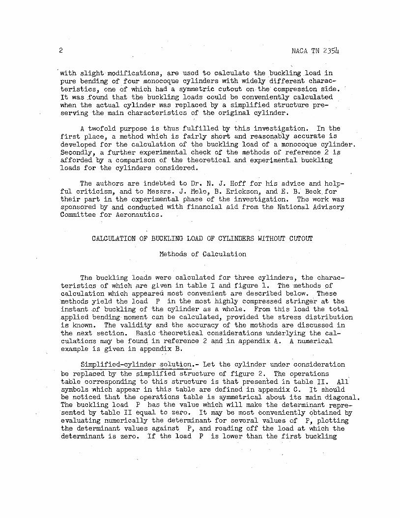
with s l i gh t modifications, a re used t o calculate the buckling load i n pure bending of four monocoque cylinders with widely different charac- t e r i s t i c s , one of which had a symmetric cutout on the compression side. It was.found tha t the buckling loads could be conveniently calculated when the actual cylinder was replaced by a simplified structure pre- serving the main character is t ics of the or iginal cylinder.
A twofold purpose i s thus f u l f i l l e d by t h i s investigation. I n the first place, a method which i s f a i r l y short and reasonably accurate i s developed f o r the calculation of the buckling load of a monocoque cylinder. Secondly, a fur ther experimental check of the methods of reference 2 i s afforded by a comparison of the theoret ical and experimental buckling loads f o r the cylinders considered.
The authors a re indebted t o D r , N. J. Hoff f o r h i s advice and help- fu l cri t icism, and t o Messrs. J. Mele, B. Erickson, and E. B. Beck.for t h e i r par t i n the experimental phase of the investigation. The work was sponsored by and conducted with f inancial a id from the National Advisory Committee f o r Aeronautics.
CALCULATION OF BUCKLING LOAD OF CYLINDERS WITHOUT CUTOUT
Methods of Calculation
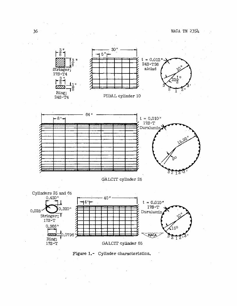
The buckling loads were calculated f o r three cylinders, the charac- t e r i s t i c s of which are given i n tab le I and f igure 1. calculation which appeared most convenient are described below. methods y ie ld the load instant of buckling of the cylinder as a whole. applied bending moment can be calculated, provided the s t r e s s dis t r ibut ion is known. the next section. Basic theoret ical considerations underlying the cal- culations may be found i n reference 2 and i n appendix A . example i s given i n appendix B.
The methods of These
P i n the most highly compressed s t r inger a t the From t h i s load the t o t a l
The va l id i ty and the accuracy of the methods are discussed i n
A numerical
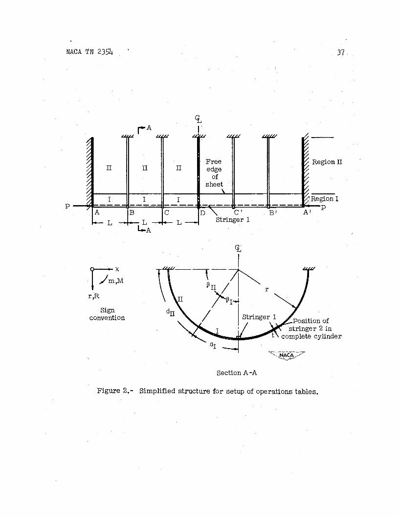
Simplified-cylinder solution.- Let the cylinder under consideration be replaced by the simplified structure of f igure 2 . The operations tab le corresponding t o t h i s s t ructure i s tha t presented i n table 11. symbols which appear i n t h i s tab le a re defined i n appendix C. be noticed tha t the operations table i s symmetrical about i t s main diagonal. The buckling load sented by tab le I1 equal t o zero. evaluating numerically the determinant f o r several values of the determinant values against determinant i s zero. If the load P i s lower than the f irst buckling
A l l It should
P has the value which w i l l make the determinant repre- It may be most conveniently obtained by
P, and reading off the load a t which the P, p lot t ing
NACA TN 2354 3
load, the determinant w i l l be posit ive (because it contains an even number of rows; see reference 2 ) . the method of reference 3, t ha t portion of the so-called “auxiliary matrix” which corresponds t o the first nine rows of tab le I1 need be
If the determinants are evaluated by
- considered only once, since it i s independent of the load P.
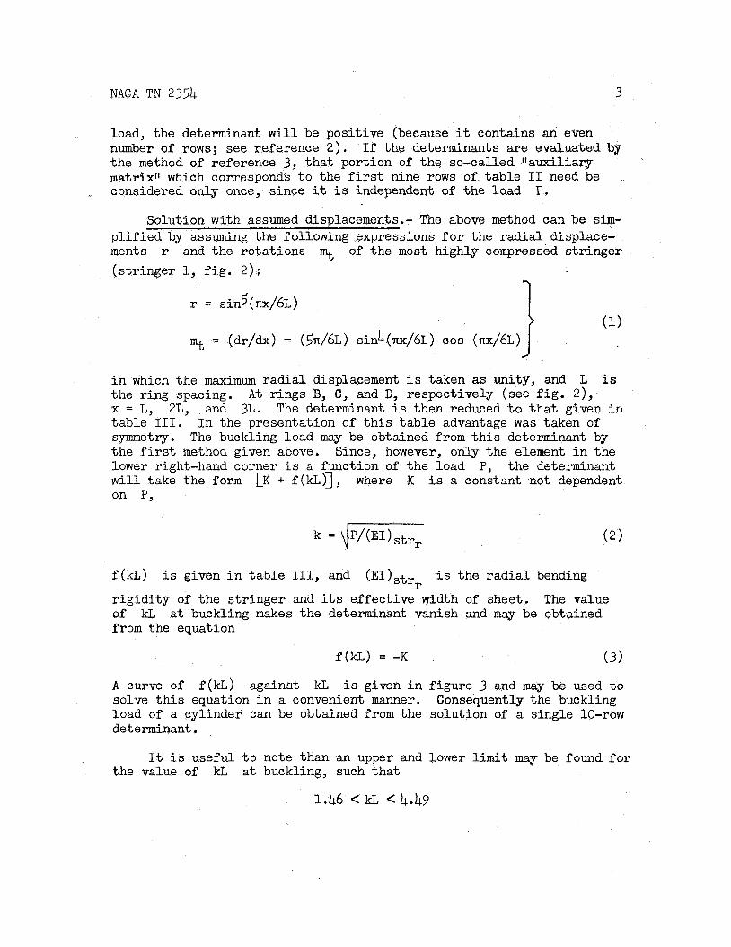
Solution with assumed displacements.- The above method can be s im- p l i f i ed by assuming the following expressions f o r the r ad ia l displace- ments r and the rotations % of the most highly compressed s t r inger (s t r inger 1, f ig . 2 ) :
(1) r = sinS(nx/6L)
3 = (dr/dx) = (5n/6L) sinb(nx/6L) cos (nx/6L)
i n which the maximum r ad ia l displacement i s taken as unity, and L i s the ring spacing. x = L, 2L, and 3L. The determinant i s then reduced t o t h a t given i n table 111. symmetry. the f i r s t method given above. Since, however, only the element i n the lower right-hand corner i s a function of the load the determinant w i l l take the form [K + f(kL)], where K i s a constant not dependent on P,
A t rings B, C, and D, respectively (see f i g . 2) ,
I n the presentation of t h i s tab le advantage was taken of The buckling load may be obtained from t h i s determinant by
P,
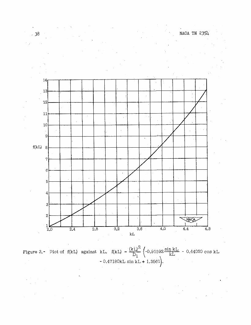
f (kL)
r i g id i ty of the s t r inger and i t s effective width of sheet. The value of kL from the equation
i s given i n tab le 111, and (EI)s t r r i s the r a d i a l bending
a t buckling makes the determinant vanish and may be obtained
f (kL) = -K ( 3 )
A curve of f (kL) against kL i s given i n f igure 3 and may be used t o solve t h i s equation i n a convenient manner. load of a cylinder can be obtained f romthe solution of a single 10-row determinant
Consequently the buckling
It i s useful t o note than an upper and lower l i m i t may be found fo r the value of kL a t buckling, such tha t
1.46 < kL < 4.49
NACA TN 2354 4
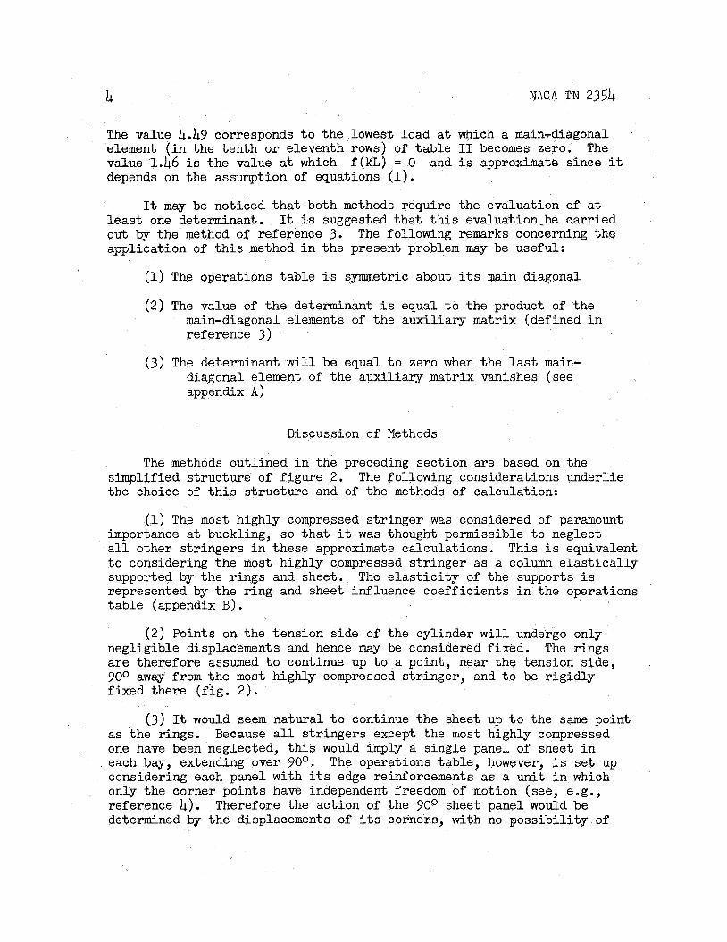
The value 4.49 corresponds t o the lowest load a t which a main-rdiagonal element ( i n the tenth o r eleventh rows) of t ab le I1 becomes zero. The value 1.46 is the value a t which f (kL) = 0 depends on the assumption of equations (1).
and i s approximate since it
It may be noticed t h a t both methods require the evaluation of a t l e a s t one determinant. out by the method of reference 3. application of t h i s method i n the present problem may be useful:
It i s suggested t h a t t h i s evaluation-be carr ied The following remarks concerning the
(1) The operations tab le i s symmetric about i t s main diagonal
( 2 ) The value of t h e determinant i s equal t o the product of the main-diagonal elements of the auxi l iary matrix (defined i n reference 3)
( 3 ) The determinant w i l l be equal t o zero when the l a s t main- diagonal element of the auxi l iary matrix vanishes (see appendix A)
Discussion of Methods
The methods outlined i n the preceding sect ion are based on the simplified s t ructure of f igure 2. the choice of t h i s s t ructure and of the methods of calculation:
The following considerations underlie
(1) The most highly compressed s t r inger was considered of paramount importance a t buckling, s o t h a t it w a s thought permissible t o neglect a l l other s t r ingers i n these approximate calculations. This i s equivalent t o considering the most highly compressed s t r inger as a column e l a s t i c a l l y supported by the rings and sheet. represented by the r ing and sheet influence coeff ic ients i n the operations tab le (appendix B) .
The e l a s t i c i t y of the supports i s
( 2 ) Points on the tension side of the cylinder w i l l undergo only negligible displacements and hence may be considered fixed. are therefore assumed t o continue up t o a point, near the tension side, 900 away f romthe most highly compressed s t r inger , and t o be r ig id ly f ixed there ( f ig . 2 ) .
The rings
( 3 ) It would seem natural t o continue the sheet up t o the same point as the rings. Because a l l s t r ingers except the most highly compressed one have been neglected, t h i s would imply a single panel of sheet i n each bay, extending over 90°. considering each panel with i t s edge reinforcements as a uni t i n which only the corner points have independent freedom of motion (see, e.g., reference 4). determined by the displacements of i t s corners, with no poss ib i l i ty of
The operations table , however, i s s e t up
Therefore the action of the 90° sheet panel would be
NACA TN 235k 5
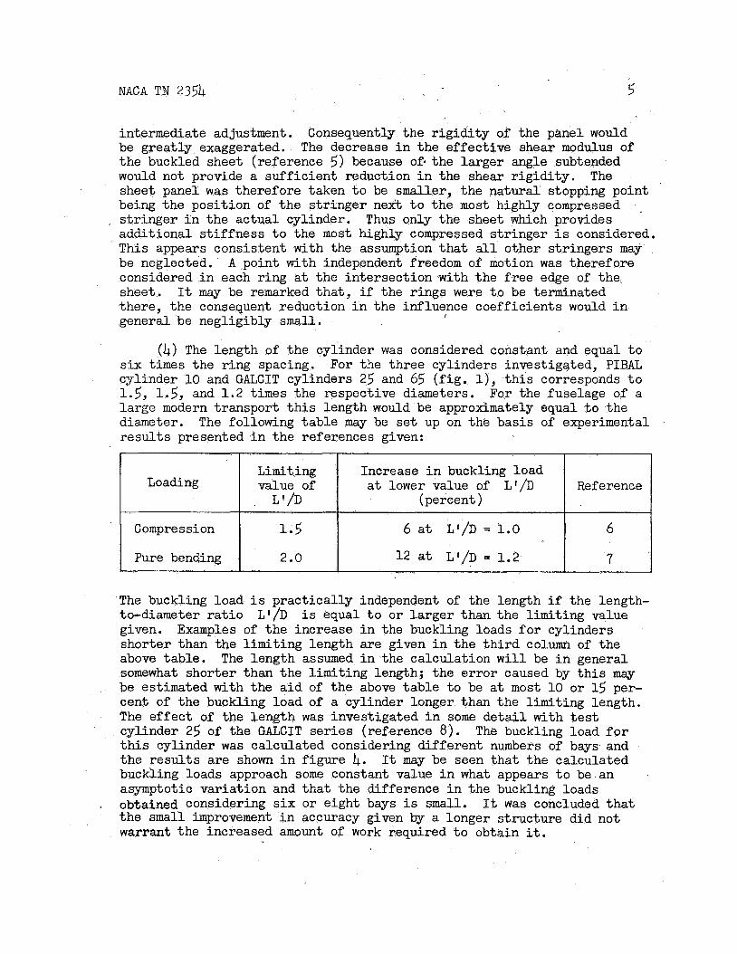
intermediate adjustment. be great ly exaggerated. the buckled sheet (reference 5) because of. the larger angle subtended would not provide a suf f ic ien t reduction i n the shear r ig id i ty . sheet panel w a s therefore taken t o be smaller, the natural stopping point being the posit ion of the s t r inger ne i t t o the most highly compressed s t r inger i n the actual cylinder. additional s t i f fnes s t o the most highly compressed s t r inger i s considered. This appears consistent with the assumption t h a t all other s t r ingers may be neglected. considered i n each r ing a t the intersect ion with the f r ee edge of the sheet. there, the consequent reduction i n the influence coefficients would i n general be negligibly small.
Consequently the r ig id i ty of the panel would The decrease i n the effect ive shear modulus of
The
,
Thus only the sheet which provides
A point with independent freedom of motion w a s therefore
It may be remarked tha t , i f the rings were t o be terminated
I
(4) The length of the cylinder w a s considered constant and equal t o six t i m e s the ring spacing. For the three cylinders investigated, PIBAL cylinder 10 and GALCIT cylinders 25 and 65 ( f ig . l), t h i s corresponds t o 1.5, 1.5, and 1 . 2 times the respective diameters. For the fuselage of a large modern transport t h i s length would be approximately equal t o the diameter. r e su l t s presented i n the references given:
The following tab le may be s e t up on the basis of experimental
Loading
Compression
Pure bending
Limiting Increase i n buckling load value of a t lower value of L'/D Reference
1.5 6 a t L'/D = 1.0 6
L I/D (percent )
2.0 1 2 a t L I / D = 1.2 7
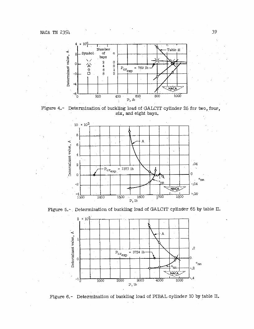
The buckling load i s pract ical ly independent of the length i f the length- to-diameter r a t i o given. shorter than the l imit ing length are given i n the t h i r d column of the above table . somewhat shorter than the l imit ing length; the e r ror caused by t h i s may be estimated with the a i d of the above tab le t o be a t most 10 or 15 per- cent of the buckling load of a cylinder longer than the l imiting length. The e f fec t of the length w a s investigated i n some d e t a i l with test cylinder 25 of the GALCIT se r ies (reference 8). The buckling load f o r t h i s cylinder w a s calculated considering different numbers of bays and the r e su l t s a re shown i n f igure 4. It may be seen tha t the calculated buckling loads approach some constant value i n what appears t o be an asymptotic variation and tha t the difference i n the buckling loads obtained considering six or eight bays i s small. the small improvement i n accuracy given by a longer structure did not warrant the increased amount of work required t o obtain it.
L1/D i s equal t o o r l a rger than the l imiting value Examples of the increase i n the buckling loads f o r cylinders
The length assumed i n the calculation w i l l be i n general
. It was concluded tha t
6 NACA TN 235h
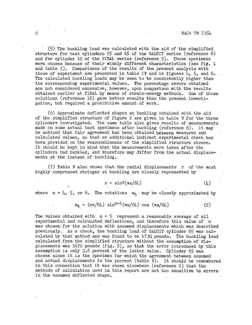
. (5) The buckling load was calculated with the a id of the simplified structure f o r t e s t cylinders 25 and 65 of the GALCIT se r ies (reference 8) and f o r cylinder 10 of the PIBAL ser ies (reference 9 ) . were chosen because of t h e i r widely different character is t ics (see f i g . 1 and table I). those of experiment are presented i n table I V and i n f igures 4, 5, and 6, The calculated buckling loads may be seen t o be consistently higher than the corresponding experimental values. are not considered excessive, however, upon comparison with the r e su l t s obtained e a r l i e r a t PIBAL by means of strain-energy methods. solutions (reference 10) gave be t t e r resu l t s than the present investi- gation, but required a prohibitive amount of work.
Those specimens
Comparisons of the r e su l t s of the present analysis with
The percentage e r rors obtained
One of those
(6) Approximate deflected shapes a t buckling obtained with the a id of the simplified s t ructure of f igure 2 are given i n tab le V f o r the three cylinders investigated. The same table also gives resu l t s of measurements made on some actual t es t specimens a f t e r buckling (reference 6). It may be noticed tha t f a i r agreement has been obtained between measured and calculated values, s o t ha t an additional indirect experimental check has been provided on the reasonableness of the simplified structure chosen. It should be kept i n mind tha t the measurements were taken a f t e r the cylinders had buckled, and therefore may d i f f e r from the actual displace- ments at the instant of buckling.
( 7 ) Table V a l so shows tha t the rad ia l displacements r of the most highly compressed s t r inger a t buckling are closely represented by
r = sinn(nx/6L) (4) where n = 4, 5, o r 6. The rotations % may be closely approximated by
m t = (nn/6L) sinn-’(nx/6L) cos (nx/6L) (5)
The values obtained with experimental and calculated deflections, and therefore t h i s value of n was chosen f o r the solution with assumed displacements which was described previously. culated by tha t method and was found t o be 173Q pounds. ?he buckling load calculated from the simplified structure without the assumption of dis- placements was 1670 pounds ( f ig . 5), so t ha t the e r ror introduced by t h i s assumption i s only 3.6 percent of the l a t t e r value. chosen since it i s the specimen f o r which the agreement between assumed and actual displacements i s the poorest ( table V) . i n t h i s connection tha t it was shown elsewhere (reference 2 ) t ha t the methods of calculation used i n t h i s report are not too sensit ive t o e r rors i n the assumed deflected shape.
n = 5 represent a reasonable average of a l l
A s a check, the buckling load of GALCIT cylinder 65 was cal-
Cylinder 65 was
It should be remembered

NACA TN 2354 7
(8) The operations tables f o r the simplified structure (tables I1 and 111) may be put i n nondimensional form by the following process. Divide the tenth and eleventh rows and columns by rows and columns (10) through (14) by the quantity column terms appearing i n the lower right-hand comer may then be writ ten as ( E I ) s t r r I , 3 times some function of kL. The ring influence coef-
f i c i e n t s s, rm, rt, and so f o r t h are equal t o (EI4./d3 multiplied by some function of r/d (reference 11). If all rows and columns are divided through by tab le w i l l be a function of the four nondimensional parameters
L, and a l l terms i n Gefftd/L. The beam-
n -
(EI),/d3 it will be noticed tha t the operations
I
where r i s the cylinder radius, (EI) , the bending r ig id i ty of a r ing i n i t s own plane, d the circumferential s t r inger spacing, Geff the effect ive shear modulus f o r the sheet, t the sheet thickness, and the other symbols have been previously defined. extensional deformations of the rings, respectively, a re represented by the two additional parameters:
The e f fec ts of shearing and
where 1, i s the moment of i n e r t i a of the ring cross section, A, i s the area of the ring, and Ar* cross section. parameters i s i n general negligible.
i s the effective shear area of the ring Reference 11 shows, however, t ha t the e f fec t of these two
It has been shown i n reference 1 2 t ha t the buckling load of a mono- coque cylinder depends on the parameter A . Two additional parameters
8 NACA TN 2354
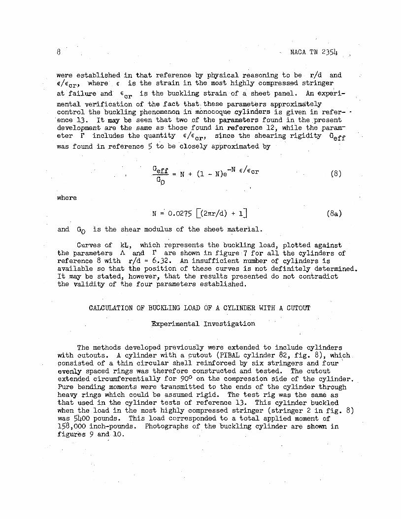
were established i n tha t reference by physical reasoning t o be E/E,-.~, where E i s the s t r a i n i n the most highly compressed s t r inger at failure and ECr i s the buckling s t r a i n of a sheet panel. An experi- mental ver i f icat ion of the f a c t t h a t these parameters approximdtely control the buckling phenomenon i n monocoque cylinders i s given i n refer- ence 13. development a re the same as those found i n reference 12, while the param- e t e r includes the quantity since the shearing r ig id i ty Geff was found i n reference 5 t o be closely approximated by
r/d and
It may be seen tha t two of the parameters found i n the present
, - - -N E / E C r Geff - N + (1 - N)e GO ,
where
N =' 0.0275 [(2rtr/d) + 1)
and Go i s the shear modulus of the sheet material.
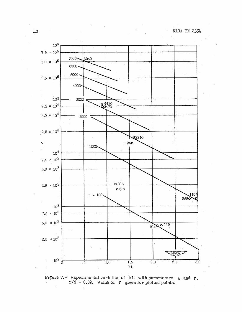
the parameters A and r are shown i n f igure 7 f o r a l l the cylinders of reference 8 with r/d = 6.32. available so t h a t the posit ion of these curves i s not def in i te ly determined. It may be stated, however, t h a t the r e su l t s presented do not contradict the va l id i ty of the four parameters established.
Curves of kL, which represents the buckling load, plotted against
An insuff ic ient number of cylinders is
CALCULATION OF BUCKLING LOAD OF A CYLINDER WITH A CUTOUT
Experimental Investigation
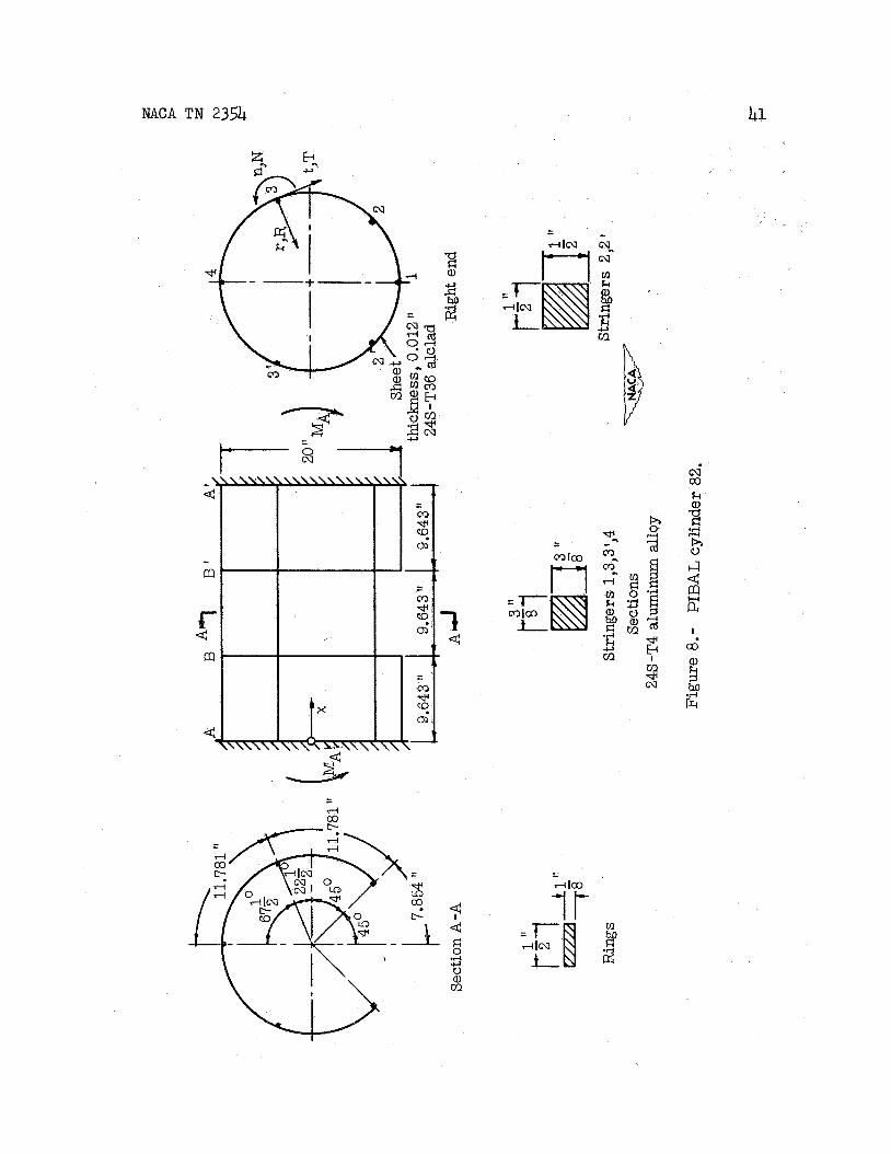
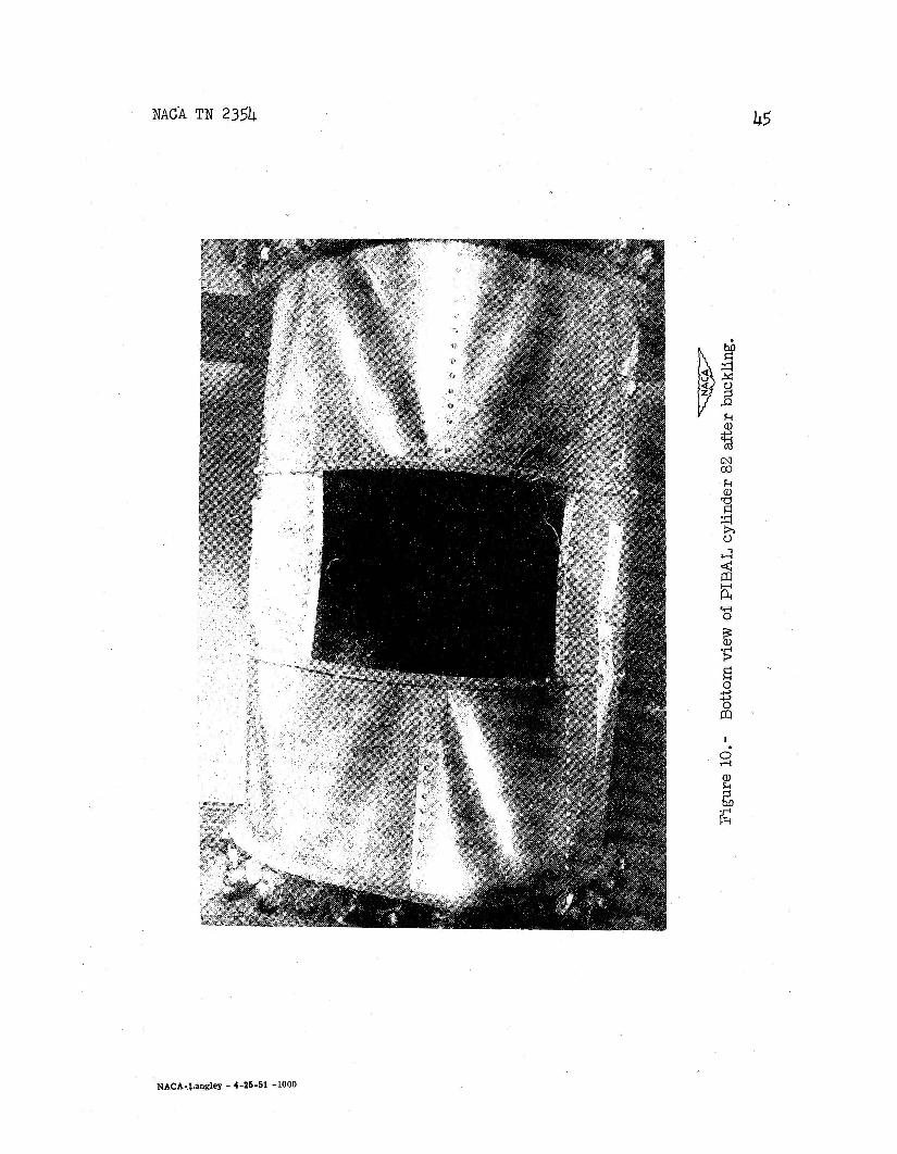
The methods developed previously were extended t o include cylinders with cutouts. consisted of a t h i n c i rcu lar she l l reinforced by six st r ingers and four ' evenly spaced rings was therefore constructed and tested. extended circumferentially f o r 90° on the compression side of the cylinder. Pure bending moments were transmitted t o the ends of the cylinder through heavy rings which could be assumed r ig id . t h a t used i n the cylinder t e s t s of reference 13. when the load i n the most highly compressed s t r inger (s t r inger 2 i n f i g . 8) w a s 5400 pounds. 158,000 inch-pounds. f igures 9 and 10.
A cylinder with a cutout (PIBAL cylinder 82, f i g . 8) , which
The cutout
The t e s t r i g was the same as This cylinder buckled
This load corresponded t o a t o t a l applied moment of Photographs of the buckling cylinder are shown i n
NACA TN 2354 9
Method of Calculation W
The results of t h e theore t ica l investigation simplified methods evolved f o r complete cylinders
iadicated t h a t t he are not sa t i s fac tory
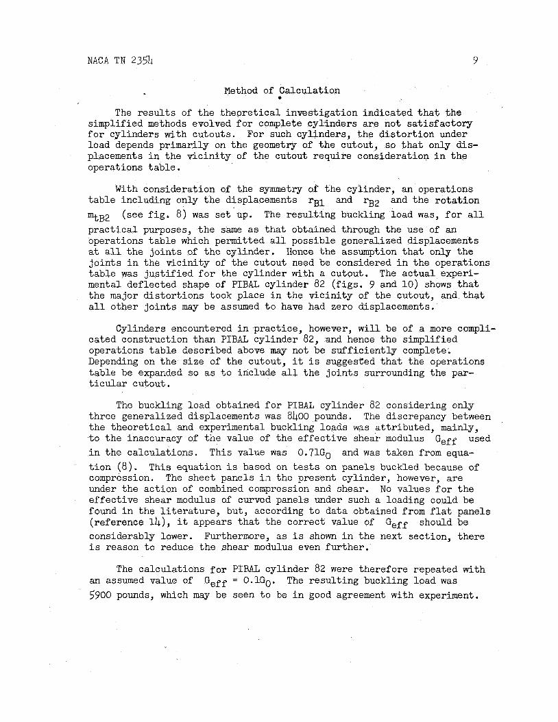
f o r cylinders with cutouts. For such cylinders, the d i s to r t ion under load depends primarily on t h e geometry of the cutout, so t h a t only dis- placements i n the v ic in i ty of the cutout require consideration i n t h e operations table .
With consideration of the symmetry of the cylinder, an operations tab le including only the displacements r B 1 and rB2 and the ro ta t ion
%B2 prac t ica l purposes, t he same as tha t obtained through the use of an operations tab le which permitted a l l possible generalized displacements a t a l l t he jo in t s of t he cylinder. j o in t s i n the v ic in i ty of the cutout need be considered i n the operations tab le w a s j u s t i f i ed f o r the cylinder with a cutout. The ac tua l experi- mental deflected shape of PIBAL cylinder 8 2 ( f igs . 9 and 10) shows t h a t the major d i s tor t ions took place i n the v i c in i ty of the cutout, and t h a t a l l other j o in t s may be assumed t o have had zero displacements.
(see f i g . 8) was set up. The resul t ing buckling load was, f o r a l l
Hence the assumption t h a t only t h e
Cylinders encountered i n practice, however, w i l l be of a more compli- cated construction than PIBAL cylinder 82, and hence the simplified operations t ab le described above may not be suf f ic ien t ly complete. Depending on the s ize of the cutout, it i s suggested t h a t the operations table be expanded s o as t o include a l l t he jo in t s surrounding the par- t i c u l a r cutout.
The buckling load obtained f o r PIBAL cylinder 82 considering only three generalized displacements was 8400 pounds. the theore t ica l and experimental buckling loads w a s a t t r ibuted, mainly, t o t he inaccuracy of t he value of the e f fec t ive shear modulus i n the calculations. This value was 0.71G0 and w a s taken from equa- t i o n ( 8 ) . compression. The sheet panels i.7 the present cylinder, however, a re under the act ion of combined compression and shear. No values f o r t he effect ive shear modulus of curved panels under such a loading could be found i n the l i t e r a t u r e , but, according t o data obtained from f l a t panels (reference l4), it appears t h a t the correct value of considerably lower. Furthermore, as i s shown i n the next section, there i s reason t o reduce the shear modulus even fur ther .
The discrepancy between
used Geff
This equation i s based on tests on panels buckled because of
Geff should be
The calculations f o r PIBAL cylinder 8 2 were therefore repeated with an assumed value of 5900 pounds, which may be seen t o be i n good agreement with experiment.
Geff = 0.1G0. The resul t ing buckling load was

10 NACA TN 2354
Reduced Effective Shear Modulus
If a panel of sheet i s not i n a buckled state, the r e l a t ion between shear stress T and shear s t r a i n y i s simply Hooke's l a w :
T = GOY ( 9 )
If the panel i s i n a buckled state, a r e l a t ion analogous t o equation ( 9 ) w i l l s t i l l hold between the average shear stress T~~ and the average shear s t r a i n yav, provided t h a t an e f fec t ive shear modulus Geff i s used i n place of ' GO. I n other words,
and Geff = Go i f the panel i s not buckled. The value of Geff w i l l represent the complex state of stress of t he buckled panel, and w i l l presumably vary with panel dimensions and type of loading.
The value of Geff i s the proportionali ty fac tor between the average shear stress and the average shear s t r a in . I n problems of i n s t ab i l i t y , however, it i s desired t o know the r e l a t ion between a small increase i n stress d('cav) and a small increase i n s t ra in d ( ya, ) . This re la t ion w i l l again have the same f o r m as equation ( 9 ) , i f only a reduced effect ive shear modulus Geffred i s used i n place of Go. I n other words,
Thus t h i s new modulus represents t he resis tance the panel w i l l offer against d i s tor t ions additional t o those represented by yav. According t o the previous discussion, t h i s new modulus will also depend upon the dimensions of the panel and upon the amount of shearing and compressive loads present.
If equation (10) i s wri t ten i n d i f f e r e n t i a l form as
comparison with equation (11) indicates t h a t
NACA TN 2354 11
The following remarks may be made about the reduced effect ive shear
red: modulus Geff
(l) Geffred = G o when the panel i s not i n a buckled s t a t e
( 2 ) Geffred = Geff when the average shearing s t r a i n i n the panel
i s zero immediately'before buckling . %
(3 ) Geffred = Geff when there i s no change of shearing s t r a i n
during buckling of the structure under consideration
(4) Geffred < Geff i n a l l other cases, since i n general the modulus
Geff decreases with increasing shear s t r a i n yav, so t h a t the second term i n the right-hand side of equation (13) i s negative
The l a t t e r case applies t o the cylinder with a cutout. The low value assumed f o r the shear modulus i n the calculations i s therefore plausible.
Polytechnic Ins t i t u t e of Brooklyn Brooklyn, N. P., August 31, 1948
1 2 NACA TN 2354
APPENDIX A
BASIC THEORY
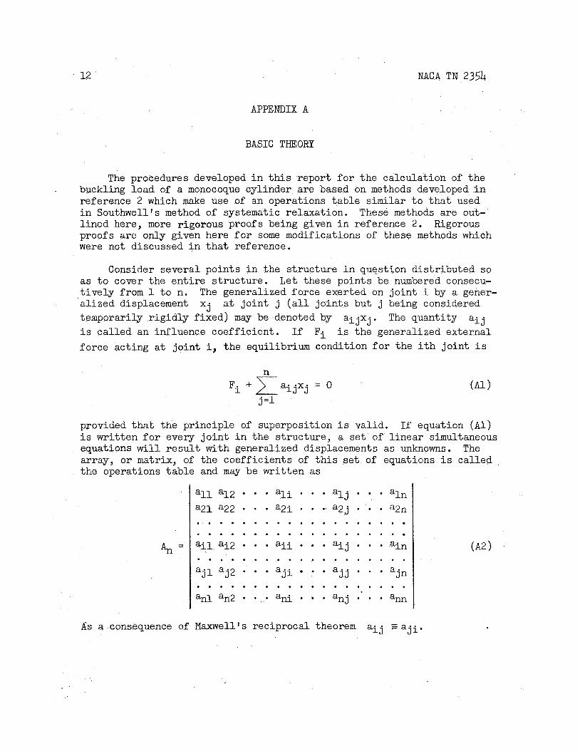
The procedures developed i n t h i s report f o r t he calculation of t he buckling load of a monocoque cylinder are based on methods developed i n reference 2 which make use of an operations tab le similar t o t h a t used i n Southwell’s method of systematic relaxation. These methods are out- l ined here, more rigorous proofs being given i n reference 2. Rigorous proofs a re only given here f o r some modifications of these methods which were not discussed i n t h a t reference.
Consider several points i n the s t ructure i n question dis t r ibuted so L e t these points be numbered consecu-
a t j o in t j ( a l l j o in t s but j being considered
as t o cover the en t i r e s t ructure . t i v e l y from 1 t o n. ‘alized displacement x j ternporarily r ig id ly f ixed) may be denoted by aijxj . The quantity a i j i s cal led an influence coeff ic ient . If F i i s the generalized external force acting a t j o in t i, the equilibrium condition f o r the i t h jo in t i s
The generalized force exerted on jo in t i by a gener-
n Fi +)aijxj = o
j =1
provided t h a t the pr inciple of superposition i s valid. i s wri t ten f o r every j o i n t i n the s t ructure , a s e t of l inear simultaneous equations w i l l result with generalized displacements as unknowns. array, o r matrix, of the coeff ic ients of t h i s s e t of equations i s cal led the operations t ab le and may be wr i t ten as
If equation (Al)
The
An =
all a12 a21 a22 . . . . . . . . a i l ai2
“ j l “ j 2
an1 an2
. . . .
. . . .
a l j aln . . . a2i . . . a2j . . . azn
. . . a i i , . . a i j . . . ain
- a j i * a j j - “jn
an i . . . anj . .
. . , a l i . .
. . . . . . . . . . . . . . . . . . . . . . . . . . . . . .
. . . . . . . . . . . . . . .
. . . . . . . . . . . . . . . . . . ann
- A s a consequence of Maxwell’s reciprocal theorem a i j = a j i .
NACA TN 2354 13
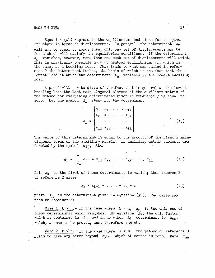
Equation (Al) represents t he equilibrium conditions f o r the given s t ructure i n terms of displacements. I n general, the determinant An will not be equal t o zero; then, only one set of displacements may be found which w i l l s a t i s f y the equilibrium conditions. If the determinant An This i s physically possible only at neutral equilibrium, or , which i s the same, a t a buckling load. This leads t o what was cal led i n refer- ence 2 t he Determinant Method, the basis of which i s the f a c t tha t the lowest load a t which the determinant load.
vanishes, however, more than one such set of displacements w i l l exist.
An vanishes i s the lowes t buckling
A proof w i l l now be given of the f a c t t ha t i n general a t the lowest buckling load the las t main-diagonal element of the auxi l iary matrix of the method f o r evaluating determinants given i n reference 3 i s equal . to zero. Let the symbol A i stand f o r the determinant
all a12 * ali
a21 a22 a2i (A3)
The value of t h i s determinant i s equal t o the product of t he f i r s t i main- diagonal t e r m s of the auxi l iary matrix. denoted by the symbol a i j , then
If auxiliary-matrix elements a re
A i = f a j j = all a22 akk . a i i (A4 1 j =1
L e t of reference 2 gives
Ak be the f irst of these determinants t o vanish; then theorem 2
where A, i s the determinant given i n equation ( A 2 ) . Two cases may then be considered:
Case 1; k = n.- In the case where k = n, An i s the only one of these determinants which vanishes. By equation ( A b ) the only f ac to r which i s contained i n An and i n no other A i determinant i s ann, which, as w a s t o be proved, must therefore vanish.
Case 2; k < n.- I n the case where k < n, the method of reference 3 f a i l s t o give any terms beyond ukk, which of course i s zero. Here a,
-4 NACA TN 2354
A t =
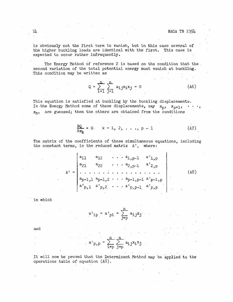
i s obviously not the f irst term t o vanish, but i n t h i s case several of the higher buckling loads a re ident ica l with the first. expected t o occur ra ther infrequently.
This case i s
The Energy Method of reference 2 i s based on the condition tha t the second variation of the t o t a l potent ia l energy must vanish a t buckling. This condition may be writ ten as
. . . . . . . ' . . . * . . . . . . . ap-1,1 ap-1,2 * * * "p-1,p-1 a'p-1,p
a'PYl PY2. a ' P,P+ PYP a t . . .at
This equation i s sa t i s f i ed a t buckling by the buckling displacements. In . the Energy Method some of these displacements, say xp, xp+l, - 0 ,
xn, are guessed; then the others are obtained from the conditions
% = O k = l , 2 , . . ' Y P - 1 axk
The matrix of the coefficients of these simultaneous equations, including the constant terms, i s the reduced matrix A , where:
i n which
It will now be proved tha t the Determinant Method may be applied t o the operations table of equation ( A 8 ) .

NACA TN 2354
A l l , l e s s than zero
Varying; none, zero
All, greater than zero
Some, zero; a l l others, negative
It i s well-known (see reference 15) t ha t any quadratic form Q put i n the form
may be
n
(A9 1
Q < 0 always Negative def ini te (Q = o i f x- 0 ) nonsingdar
negative, o r zero nonsingular
J
Q may be positive, Indefini te
Q > 0 always Positive def in i te ( Q = 0 i f Xj 0 ) nonsingular
Q = 0 o r Negative def in i te Q < 0 singular
where the b i quant i t ies are constants, and
Some, zero; others, varying
n
j =1 L i => C jXj
may be positive, Indefini te singular negative, o r zero '
where the c j quant i t ies are constants. n l inear ly independent quant i t ies L i . This assumption en ta i l s no l o s s of generality since i n the case i n which it i s not' t rue some of the constants b i w i l l be zero.
It i s assumed tha t there a re
By means of equation ( A 9 ) and table 2 of reference 2 the following tab le may be s e t up:
Some, zero; a l l others, positive
I I
Q = 0 o r Positive def ini te Q > 0 singular
Sign of b i I Sign of Q IClassification of Q I I
I I I
Type of 3quilibrium
Stable
Unstable
Unstable
Neutral
Unstable
Unstable
16 NACA T N 235L
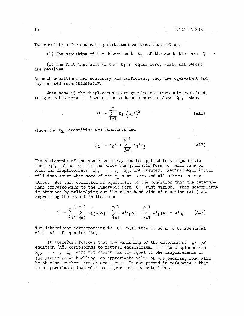
Two conditions f o r neutral equilibrium have been thus set up:
(1) The vanishing of the determinant An of the quadratic form Q
(2) The f a c t t h a t some of the bits equal zero, while a l l others are negative
A s both conditions are necessary and suf f ic ien t , they are equivalent and may be used interchangeably.
When some of the displacements are guessed as previously explained, the quadratic form Q becomes the reduced quadratic f o r m & I , where
P
i=l Q' = bii ' (Li i ' )*
where the b i t quant i t ies are constants and
P-1 Lit = c 1 +
C j ' X j j =1 P
The statements of the above,table my now be applied t o the quadratic form Q', since Q' i s the value the quadratic form Q will take on when the displacements xp, . . ., Xn. are assumed. Neutral equilibrium w i l l then exist when some of t he b i t s are zero and a l l others a re neg- a t ive. nant corresponding t o the quadratic form Qi' must vanish. This determinant i s obtained by multiplying out t h e right-hand side of equation ( A l l ) and expFessing the l e s u l t i n the f o r m
But t h i s condition i s equivalent t o the condition tha t the determi-
The determinant corresponding t o QI w i l l then be seen t o be ident ica l with A ' of equation (AB) .
It therefore follows t h a t the vanishing of the determinant A' of If the displacements equation ( A 8 ) corresponds t o neutral equilibrium.
the s t ructure a t buckling, an approximate value of the,buckling load w i l l be obtained rather than an exact one. t h i s approximate load w i l l be higher than the actual one.
- 0 , xn were not chosen exactly equal t o the displacements of xP,
It was proved i n reference 2 t h a t
NACA TN 2354 17
APPENDIX B 1
GENERAL FORMULAS AND NUMERICAL EXAMPLE
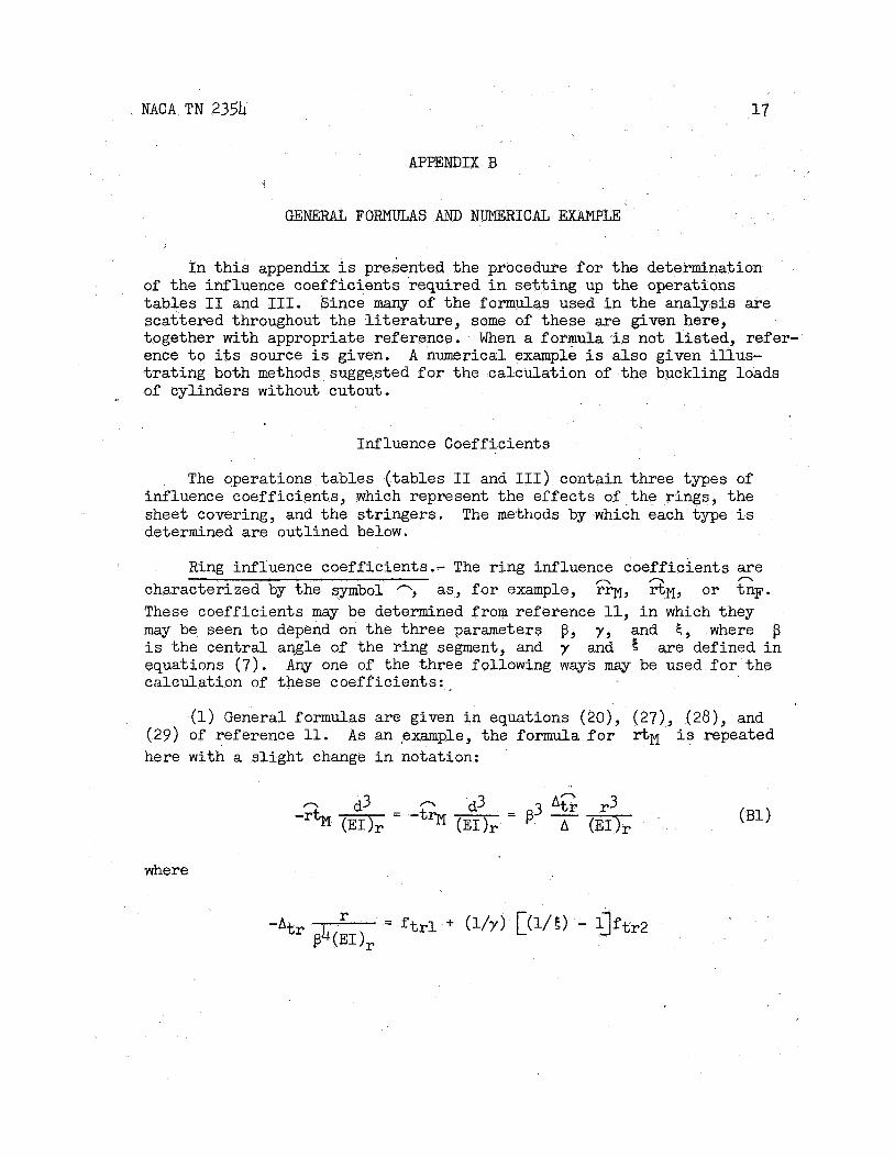
I n t h i s appendix i s presented the procedure f o r the determination of the influence coeff ic ients required i n se t t i ng up the operations tables I1 and 111. Since many of the formulas used i n the analysis are scattered throughout the l i t e r a tu re , some of these are given here, together with appropriate reference. When a formula i s not l i s t ed , refer- ence t o i t s source i s given. t r a t ing both methods sugge,sted f o r the calculation of the buckling loads of cylinders without cutout.
A numerical example i s a l so given i l l u s -
Influence Coefficients
The operations tab les ( tables I1 and 111) contain three types of influence coefficients, which represent the e f fec ts of the rings, the sheet covering, and the s t r ingers . The methods by which each type i s determined are outlined below.
Ring influence coefficients.- The r ing influence coefficients a re characterized by the symbol -, as, f o r example, rrM, r t M , o r tnF. These coefficients may be determined from reference 11, i n which they may be seen t o depend on the three parameters $, y , and E , where p i s the central angle of the ring segment, and y and !5 are defined i n equations (7) . calculation of these coeff ic ients : .
n n n
Any one of the three following ways may be used f o r the
(1) General formulas a re given i n equations (20), (27) , (28), and (29) of reference 11. A s an #example, the formula f o r r t ~ i s repeated here with a s l i gh t change i n notation:
where
18 NACA TN 2354
and
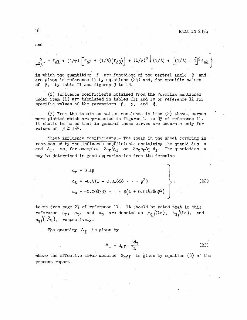
i n which the quant i t ies f are functions of the central angle p and are given i n reference 11 by equations (24) and, f o r specif ic values of p, by table I1 and f igures 3 t o 13.
( 2 ) Influence coeff ic ients obtained from the formulas mentioned under i t e m (1) are tabulated in- tables I11 and I V of reference 11 f o r specific values of the parameters B y y , and 6.
(3) From the tabulated values mentioned i n item ( 2 ) above, curves were plotted which are presented i n f igures 14 t o 85 of reference 11. It should be noted t h a t i n general these curves are accurate only f o r values of p 2 150.
Sheet influence coefficients.- The shear i n the sheet covering i s represented by the influence coefficients containing the quant i t ies a and AI, as, f o r example, 2ar2A1 o r 2atu&1 dI. The quant i t ies a
may be determined i n good approximation from the formulas
(B2 1
ar = 0. lg
at = -0.5(1 - 0.01666 - * p2)
an = -0.008333 p(1 + 0.014286p2)
taken from page 27 of reference 11. reference a,, a t , and an are denoted as rq/(Lq), tq/(Lq), and %/(L2q), respectively.
It should be noted t h a t i n t h i s
The quantity AI i s given by
where the effect ive shear modulus present report.
Geff i s given by equation (8) of the
NACA TN 23.5’4 1 9
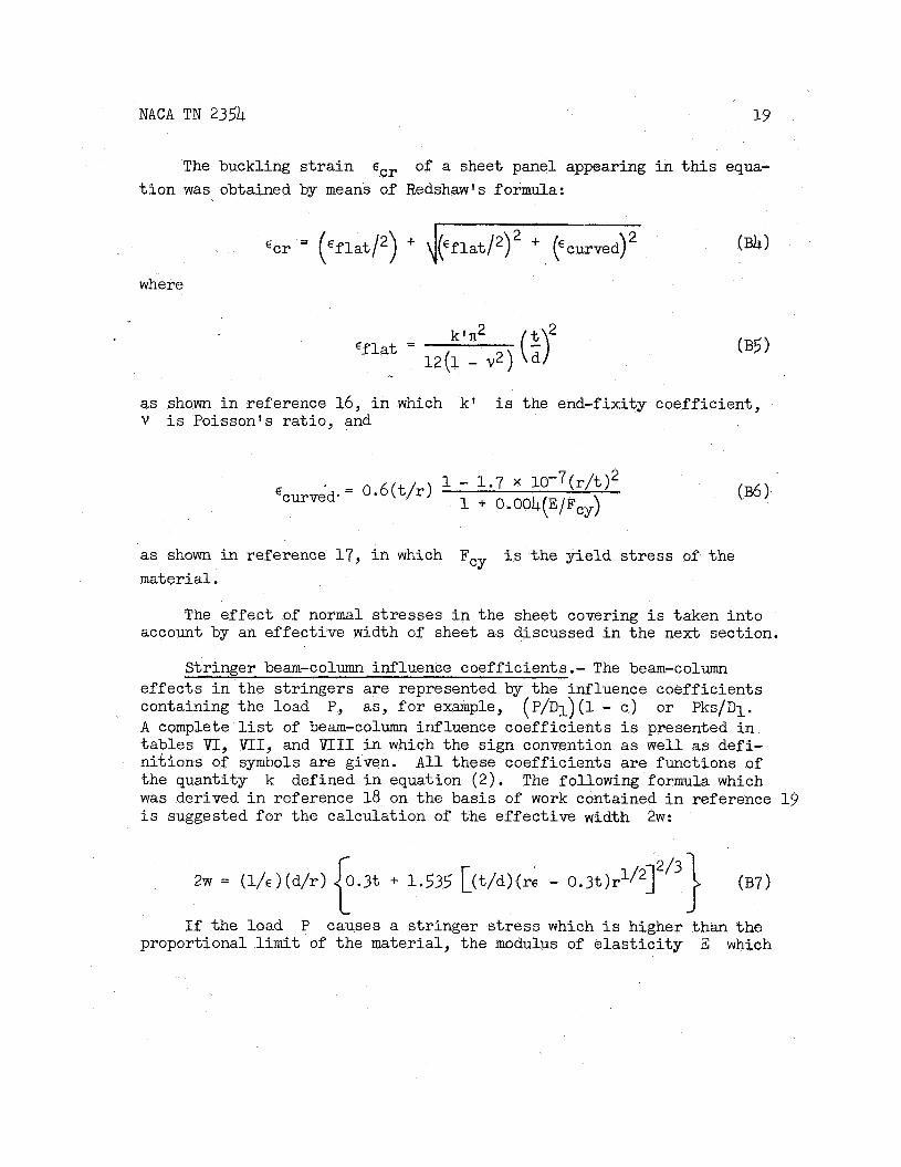
The buckling s t r a i n 6cr of a sheet panel appearing i n t h i s equa- t i o n w a s obtained by means of Redshawls formula:
where
€ f l a t =
2 \jpf 1at/2) + (“curved)
kfn2
1 2 ( 1 - v2)
as shown i n reference 16, i n which k 1 i s V i s Poisson’s r a t i o , and
the end-fixity coefficient,
- 0 .6 ( t / r ) 1 - 1 . 7 x 1 0 - 7 ( ~ / t ) ~ 1 + 0.004(E/Fcy) ‘curved. -
as shown i n reference 1 7 , i n which F i s the y ie ld s t r e s s of the material.
CY
The e f fec t of normal s t resses i n the sheet covering i s txken in to account by an effect ive width of sheet as discussed i n the next section.
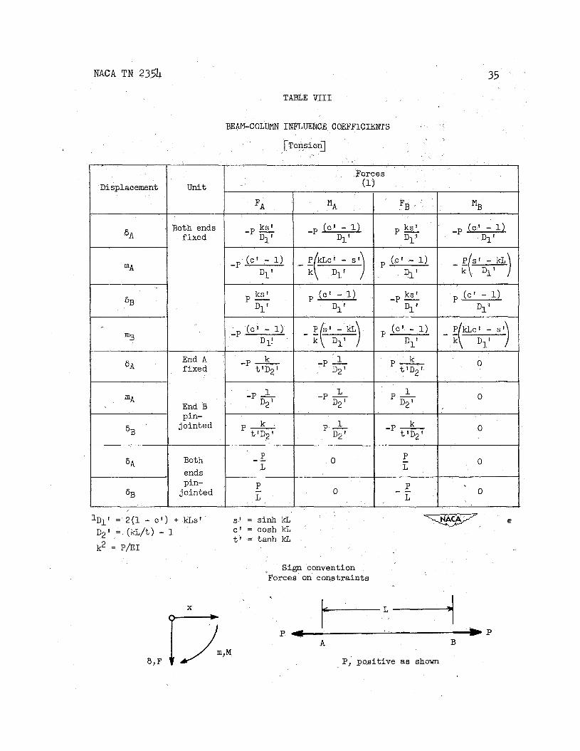
Stringer beam-column influence coefficients.- The beam-column ef fec ts i n the s t r ingers are represented by the influence coefficients containing the load P, as, f o r example, (P/D1)(1 - c ) or Pks/D1. A complete l i s t of beam-column influence coeff ic ients i s presented i n tables V I , VII, and VI11 i n which the sign convention as well as defi- ni t ions of symbols a re given. All these coeff ic ients are functions of the quantity k defined i n equation ( 2 ) . The following formula which w a s derived i n reference 18 on the basis of work contained i n reference 1 9 i s suggested f o r the calculation of the e f fec t ive width 2w:
If the load P causes a s t r inger stress which i s higher than the proportional l i m i t of the material, the modulus of e l a s t i c i t y E which

20 NACA TN 2354
appears i n equakion (2) yust be reduced i n an appropriate manner. t h i s invest igat ion Von K a d n l s formula w a s used:
I n
where E t i s the tangent modulus.
Numerical Example
A s an example of t he application of the methods suggested f o r the calculation of t h e buckling load of cylinde-rs without cutout the buckling load i s determined here f o r GALCIT cylinder 65 of reference 8. charac te r i s t ics of t h i s cylinder a re given i n f igure 1. readi ly s e t up with t h e a id of these charac te r i s t ics and the equations l i s t e d i n the previous section. fo r tab les I1 o r I11 can then be calculated.
The Table I i s
The influence coeff ic ients required
Ring influence coefficients.- The values of the r ing influence coeff ic ients corresponding t o PI, yI, and 5, (see tab le I ) happen t o appear i n tab les I11 of reference 11. However, since these tables do not contain coeff ic ients corresponding t o use values interpolated f romthe appropriate curves of reference 11. The following values were obtained for the r ing influence coefficients:
E,,, it i s necessary t o
Ring segment I Ring segment I1
rnMI p2) EI, = -20.38
tnMI A (dlz) EI, = 109.0
-1 p3) EI, = 98.43
6h M I 1 jdII) iG = 8.65
sMII(g) = -33 .O
= 33.0

NACA TN 2354
P O b )
1550
- t r M I (dip) EI, = -656.6
Ered Istrr k kL s i n kL cos kL CT Ered
(Psi) (Psi)
37,300 7.056 x lo6 4000 0.6225 2.490 0.60646 -0.79511 L
= 4999
21
A (9) = -8.531 rnFI EI,
1"3 EI, = 74.86
tr A p) = -659.7 'I E I r
Sheet influence coefficients.- The quant i t ies a of equation (B2) have the following values:
Bay I Bay I1
ar = 0.0261
= -0.499
No sheet i n t h i s bay
= -0.00218
22 NACA TN 2354
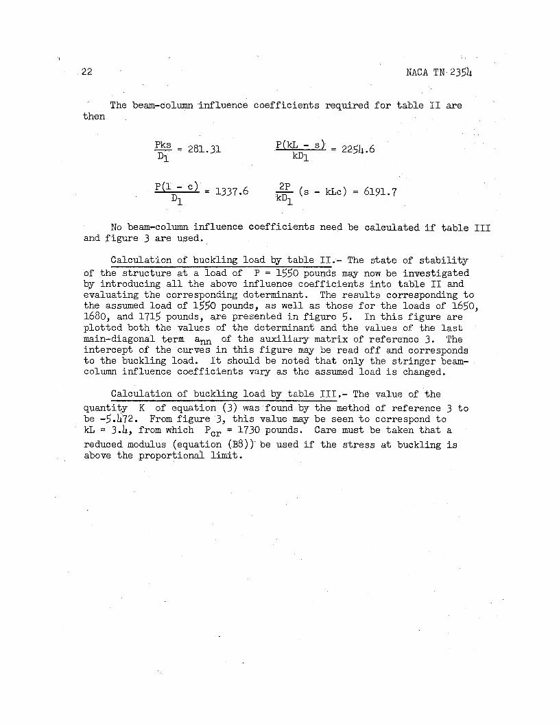
The beam-column influence coeff ic ients required f o r tab le I1 are then
- - pks - 281.31 D1
= 2254.6 kDi
-L
NO beam-column influence coefficients need be calculated if table 111 and f igure 3 are used.
Calculation of buckling load by tab le 11.- The state of s t a b i l i t y of t he s t ructure a t a load of P = 1550 pounds may now be investigated by introducing a l l t he above influence coeff ic ients i n t o t ab le I1 and evaluating the corresponding determinant. The results corresponding t o the assumed load of 1550 pounds, as well as those f o r the loads of 1650, 1680, and 1715 pounds, are presented i n f igure 5. I n t h i s f igure are plot ted both the values of the determinant and the values of the las t main-diagonal t e r m am of the auxi l iary matrix of reference 3. The intercept of the curves i n t h i s f igure may be read o f f and corresponds t o the buckling load. It should be noted t h a t only the s t r inger beam- column influence coeff ic ients vary as the assumed load i s changed.
Calculation of buckling load by table 111.- The value of the quantity K be -5.472. kL = 3.4, from which reduced modulus (equation (B8))- be used i f the stress at buckling is above the proportional l imit .
of equation (3) was found by the method of reference 3 t o From f igure 3, t h i s value may be seen t o correspond t o
Pcr = 1730 pounds. Care must be taken t h a t a
NACA TN 235’4
APPE~DIX c
SYMBOLS
A13 A 2 y * determinants o r matrices
Ai:, An
effect ive cross-sectional area of s t r inger
effect ive cross-sectional area of r ing
Aeffs t r
A,
Ar *
A’
effect ive shear area of ring cross section
reduced matrix
A, BY CY D rings
E Young s modulus
(E1 1 r
(‘1 ) s t rr
bending r ig id i ty of a ring i n i t s own plane
radial bending r ig id i ty of s t r inger and i t s effect ive width- of sheet
reduced modulus Ere d
E t tangent modulus
*CY
F i
yield-point s t ress
generalized external force
Gef f effect ive shear modulus
Ir
reduced effect ive shear modulus
shear modulus of sheet material under no com- pressive load
moment of i n e r t i a of ring cross section plus effect ive width
24 NACA T N 2354
Istrr moment of i n e r t i a of s t r inger plus effective width of sheet f o r radial bending
K constant
L r ing spacing
L i
L ~ / D
l i nea r function
r a t i o of t o t a l cylinder length t o cylinder diameter
moment causing bending of s t r inger (vector pointing i n tangent ia l direct ion)
0.0275 [(2nr/d) + l]
M t
N moment causing bending of r ing i n i t s plane; a lso
P axial s t r inger load
Pcr load i n the most highly compressed s t r inger a t the ins tan t of buckling
Q
Q' R
quadratic form
reduced quadratic f o r m
r ad ia l force
T tangent ia l force
a i j element of operations tab le
a ' i p
b i , bi' constants
element of last row o r column of reduced matrix
const ants 'j, 'j'
d circumferential s t r inger spacing
f function of p
f(kL) function of kL
i, j indices
NACA TN 2354 e
k‘ ,
mt
n
P
r
rr, rm, rt, and so f o r t h
n n n
t
2w
X
Y
E
‘cr
‘curved
end-fixity coefficient
ro ta t ion causing bending of s t r inger (vector pointing i n tangential direction)
number of s t r ingers; number of generalized displacements; rotat ion causing bending of r ing i n i t s plane
index
radius; rad ia l displacement
ring influence coeff ic ients
sheet thickness; tangential displacement
effect ive width of sheet
longitudinal axis of s t r inger
generalized displacement
parameter
parameter
awriliayy-matrix element
l a s t main-diagonal element of auxiliary matrix
functions of $ required f o r sheet influence coeff ic ients
central angle of a ring segment (d/r)
parameter; shear s t r a i n
s t r a i n i n most highly compressed s t r inger at f a i lu re
buckling s t r a i n of a sheet panel
buckling s t r a i n of nonreinforced c i rcu lar cylinder under uniform axia l compression

7
26 NACA TN 2354
‘flat buckling s t r a i n of f l a t panel under uniform compression
V Poisson’s r a t i o
f parameter
CT compressive s t r inger s t r e s s
z shear s t r e s s
Subscripts:
F f ixed
M movable
av average
exp experiment
1, 2, 3 s t r ingers
I, I1 regions
NACA TN 2354 27
REFERENCES
1. Southwell, R. V.: Relaxation Methods i n Engineering Science. A Treatise on Approximate Computations. 1940. t
2. Boley, Bruno A.: Numerical Methods f o r the Calculation of Elas t ic
The Clarendon Press (Oxford) ,
Ins tab i l i ty . Jour . Aero. Sci., vol. 14, no. 6, June 1947, PP. 337-348.
3. Grout, Prescott D.: A Short Method f o r Evaluating Determinants and Solving Systems of Linear Equations with Real o r Complex Coefficients, Trans. AIEE, vol. 60, 1941, pp. 1235-1240.
4. Hoff, N. J., Levy, Robert S., and Kempner, Joseph: Numerical Pro- cedures f o r the Calculation of the Stresses i n Monocoques. fusion of Tensile Stringer Loads i n Reinforced Panelsc NACA TN 934, 1944-
I - D i f -
5. Hoff , N. J. , and Boley, Bruno A. : The Shear Rigidity of Curved Panels under Compression. NACA TN 1090, 1946.
6. GALCIT: Some Investigations of the General In s t ab i l i t y of Stiffened Metal Cylinders. Specimens and Studies of the Buckling Phenomena of Unstiffened Circular Cylinders.
I V - Continuation of Tests of Sheet-Covered
NACA TN 908, 1943.
7 . GALCIT: Some Investigations of the General In s t ab i l i t y of Stiffened Metal Cylinders. Combined Bending and Transverse Shear.
V I - Stiffened Metal Cylinders Subjected $0
NACA TN 910 , 1943.
8 . GALCIT: Some Investigations of the General In s t ab i l i t y of Stiffened Metal Cylinders. V - Stiffened Metal Cylinders Subjected t o Pure Bending. NACA TN 909, 1943.
9. Hoff, N. J., Fuchs, S. J., and Cir i l lo , Adam J.: The Inward Bulge Type Buckling of Monocoque Cylinders. gation of the Buckling i n Combined Bending and Compression. TN 939, 1944.
I1 - Experimental Investi- NACA
10. Hoff, N. J., Klein, Bertram, and Boley, Bruno A.: The Inward Bulge Type Buckling of Monocoque Cylinders. Theory Which Assumes a More General Deflected Shape. 1948
V - Revised St ra in Energy NACA TN 1505,

11. Hoff, N . J., Klein, Bertram, and cedures f o r the Calculation of
NACA TN 2354
Libby, P a u l A.: Numerical Pro- the Stresses i n Monocoques. I V -
Influence Coefficients of Curved Bars f o r Distortions -in Their Own Plane. NACA TN 999, 1946.
1 2 . Hoff, N. J.: General I n s t a b i l i t y of Monocoque Cylinders. Jour. Aero. Sci., vol. 10, no. 4, April 1943, pp. 105-114, 130.
13. Hoff, N. J., Boley, Bruno A., and Nardo, S. V.: The Inward Bulge Type Buckling of Monocoque Cylinders. gation of Cylinders Subjected t o @re Bending. 1948
I V - Experimental Investi- NACA TN 1499,
14. Kromm, A , , and Marguerre, K. : Behavior of a Plate S t r ip under Shear and Compressive Stresses beyond the Buckling Limit. TM 870, 1938.
NACA
15. B&her, Maxime: Introduction t o Higher Algebra. The Maemillan Co., 1931.
16. Timoshenko, S.: Theory of Plates and Shells. F i r s t Ed., McGraw- H i l l Book Co., Inc., 1940.
17. Donnell, L. H.: A New Theory f o r the Buckling of Thin Cylinders under Axial Compression and Bending. Trans. A.S.M.E., vol. 56, no. 11, Nov. 1934, pp. 795-806.
18. Hoff, N . J., and Klein, Bertram: The Inward Bulge Type Buckling of Monocoque Cylinders. Buckling Stress of a Compressive Force, a Nonlinear Direct Stress Distribution, and a Shear Force. NACA TN 938, 1944.
I - Calculation of the Effect upon the
19 . Ebner, H.: The Strength of Shel l Bodies - Theory and Practice. NACA TM 838, 1937.
20. Templin, R. L., Hartmann, E. C. , and Paul, D. A , : Typical Tensile and Compressive Stress-Strain Curves for Aluminum Alloy 24S-T, Alclad 24S-T, 24S-RT, and Alclad 24s-RT Products. Tech. Paper No. 6, Aluminum Res. Lab., Aluminum Co. of Am., 1942.
NACA T N 2354
\
ln r4
ln
m d
9
- r4
N '9
-
0 r4
0 9
h
R .i v
A
v W N
b W
29
30 NACA TN 2354
r d d
nl I
0
i d' N
0
0 0
~
0
0 0
0
NACA T N 2354 31
=:
(u 3 <- “d N
=I < d 4 (u
I -
0
- u) o 0 + 3? E
ii 0 4) r- t 0
I -I
8
-
n
-
1
0 N 0 t ’ t
0 0 (E (E lJ
I I

32
Shape rB
NACA TN 2354
re
TABLE I V
0.031250
COMPARISON OF CALCULATED AND EXPERIMENTAL BUCKLING LOADS
0.48713
Method of calculation (percent)
Table II 955 . 24.2
Cylinder
GALCIT 25
GALCIT 65 Table I1 I 1670 I 1371 I 21.8
GALCIT 65 Tab3e I11 1730 1371 26.2
Table I1 4850 3754 29.2 PIBAL 10
TABLE V
ASSUMED, CALCULATED, AND EXPERIMENTAL DEFLECTED SHAPES
[For sign convention and nomenclature see f ig . 2 1
1 1 0.22672(1/L) sin4(%) I 0.06250 I 0.56250
sin5 (g) 1 1 O.O85020(1/L) si&( E) 1 0.015625 1 0.42188 I 0.76520(1/L)
I 0.80011(1/L) I ’IBAL 1 -0.016949 I 0.50229 (Calculated) 1 I 0.15086(1/L)
1 I O.O93608(1/L) 25 I 0.066323 I 0.48355 (Calculated) 0.82808 (1JL) I GALclT cy1* 65 1 -0.16089 1 0.30640 (Calculated)
I 0.667 GALCIT cyl. 25 o.222 (Experimental)
GALCIT cyl. 27 (Experimental) I 0*0370 I 0‘204
I I
cy’. 30 1 0.0588 I 0.4l.2 (ExperkntaJ.)
1 0.446 (Experimental)
NACA TN 2354 33
TABLE VI
BEAM-COLUMN INFLUENCE COEFFICIENTS
ompr press ion]
Forces
Unit Displacement FA
Both ends f ixed
1 - c -P - D1
ks P - D 1
P- 1 - c 1 -pa: 1 p- 1 - c D 1 D 1 I 6B
1 - c -P - D1
End A f ixed
k -P - t D 2
I -P - D2 End B
pin- jointed k P -
tD2 0 1 k P - 3
D2
I 6A Both ends pin-
jointed bg P L
- -
1% = 2 ( 1 - c ) - kLs s = s i n kL D2 = 1 - (kL/t)
k2 = P/EI
c = cos kL t = t a n k L
Sign convention Forces on constraints
X
Q-----) P -
A B
P, posit ive as sham

\
E 1 -6 - L2
L3
L2
E 1 -3 -
E 1 -3 -
NACA TN 235'4 .
E 1 -4 y- E 1 6- E 1 -2 - L L2
L2 L 3
L L2
0 E 1 3 - E 1 -3 -
0 E 1 3 - E 1 -3 -
TABLE V I 1
BEAM-C OL UMN INFLUENCE COEFFICIENTS
[ A x i a l end load P equal ;to zero]
Displacement
mA
6B
mB
6A
mA
6B
6B
X
Unit
Both ends fixed
End A fixed
End B pin-
jointed
Both ends pin-
j oint ed
Forces I I I
-12 - E 1 1-6: 1 12: 1-6- E 1
L 3 L2 I I I
6- E 1 EI -12 - L 3
E 1 1 2 -
I I
I I
I
Sign convention Forces on constraints
NACA TN 2354. 35
TABLE VI11
BEAM-COLUMN INFLUENCE COEFFICIENTS
Displacement unit
FA FB I MB MA
Both ends fixed 6A
(c' - 1)
D 1 ' -P
I
( c ' - 1) -P D 1!
k -P - t ' D 2 '
1 -P - D 2 '
0 End A f ixed
P A j 0 D2' End B
pin- jointed 0 k P-
t ' D 2 ' k 1 P -
D 2 '
Both ends pin-
jointed
P L
- - - L O 6A 0
0 P - 6B L
= 2(1 - c ' ) + kLs' D 2 ' = (kL/t) - 1
k2 = P/EI
s f = sinh ICL c1 = cash kL t l = tanh kL
Sign convention Forces on constraints
I X
o------) P e A rL+ B ~ P
P, positive as shown
36 NACA TN 2354
24s -T36 alclad
"
Stringer ; 17s -T4
3 t-5lAl I t
-7, Ring; 24s -T4 PIBAL cylinder 10
I I I I I I I
I I
I I I
I I
I I
1 I
I I
1
Cylinders 25 and 65 0.420 I'
0,028 " Stringer; t 175 -T 0.366 It
Rinn : l n_t 0.0796
17s IT
GALCIT cylinder 25
t = 0.010"
t = 0.010"
I
GALCIT cylinder 65
Figure 1.- Cylinder characteristics. .
NACA TN 2354
Free edge
of sheet
1
-
& L -
--I---- "-
c r A L
I1
c
I1
37
1
Q
convention
Section A-A
Figure 2.- Simplified structure for setup of operations tables.
NACA T N 2354
kL
sin kL - 0.44020 cos kL kL Figure 3.- Plot of f(kL) against kL. f(kL) =
- 0.47180kL sin kL + 1.3561 .
.
\
NACA TN 235b 39
0 200 400 600 800 1000 P, lb
Figure 4.- Determination of buckling load of GALCIT cylinder 25 for two, four, six, and eight bays.
.04
0
. -.04
-.08
Figure 5.- Determination of buckling load of GALCIT cylinder 65 by table 11.
P, l b
Figure 6.- Determination of buckling load of PIBAL cylinder 10 by table 11.
40
106
2.5 lo4
n
103
7.5 x 10²
NACA TN 2354
Figure 7.- Experimental variation of kL with parameters A and r . r/d = 6.32. Value of r given for plotted points.
NACA TN 2354


NACA T N 2354 43
t
E
-qxzJ7 Figure 9.- Side view of PIBAL cylinder 82 after buckling.

NACA TN 2354
w 0