Embed Size (px)
Citation preview

..........................................................................Collection Technique
Cahier technique n° 185
Dynamic stability of industrialelectrical networks
B. De Metz-NoblatG. Jeanjean
Merlin Gerin Square D Telemecanique

Cahiers Techniques are a collection of documents intended for engineersand technicians people in the industry who are looking for information ingreater depth in order to complement that given in display productcatalogues.
These Cahiers Techniques go beyond this stage and constitute praticaltraining tools.They contain data allowing to design and implement electrical equipement,industrial electronics and electrical transmission and distribution.Each Cahier Technique provides an in-depth study of a precise subject inthe fields of electrical networks, protection devices, monitoring and controland industrial automation systems.
The latest publications can be remote-loaded on Internet from theSchneider server.code: http://www.schneider-electric.comsection: expert ’ s place
Please contact your Schneider representative if you want either a CahierTechnique or the list of available titles.
The « Cahiers Techniques » collection is part of the Groupe Schneider’s« Collection Technique ».
Fore wor dThe author disclaims all responsibility further to incorrect use of informationor diagrams reproduced in this document, and cannot be held responsiblefor any errors or oversights, or for the consequences of using informationand diagrams contained in this document.
Reproduction of all or part of a Cahier Technique is authorised with theprior consent of the Scientific and Technical Division. The statement« Extracted from Schneider Cahier Technique no..... (please specify) » iscompulsory.

CT 185 / pp.1
n° 185Dynamic stability of industrialelectrical networks
Benoît de METZ-NOBLAT
ESE engineer, after a period with the Groupe Saint-Gobain he joinedMerlin Gerin in 1986. He is currently in charge of the Electrical SystemAnalysis Department, responsible for studying electrical phenomenaconcerning network operation and interaction with equipment anddevices.
Gérard JEANJEAN
Engineer with MERLIN GERIN since 1980, he joined the ElectricalSystem Analysis Department in 1984 to work on industrial networkstudies with special emphasis on dynamic stability studies. Hespecialises in disturbances and dependability of electrical networks.
E/CT 185 first issued june 1997
CT 185 / pp.2
Glossary
H:Inertia constant, homogeneous with a period oftime, characterising the sensitivity of speed of amachine to variations in electrical power.
Internal angle (δ):Angle between the vector representing thesupply voltage of a machine and the vectorrepresenting its electromotive force.
Electrical distance:Connection impedance. Two electricalconnections of the same length may have verydifferent electrical distances.
Load flow:Balance of the active and reactive powersexchanged on the connections of a network.
Voltage plan:Set of automatic and manual proceduresscheduled to keep the network within its ratedoperating voltage limits.
Synchronising power:Characterises the operating point of a generator:ratio of the variation in supplied power over thevariation in internal angle. The lower this ratio,the greater the risk of loss of synchronism inoverspeed.
Transient reactance:Impedance of a machine in the first second aftera disturbance.
Subtransient reactance:Impedance of a machine in the first100 milliseconds after a disturbance.
Redundancy:Used in a technical context, this term no longerhas its accepted meaning of « superfluous ».Redundancy in this case is the implementationof more than one channel to perform a functionin order to prevent failure and/or to allowmaintenance during operation withoutinterruption of operation.
Primary, secondary adjustment:For generator regulation, describes thefrequency/active power characteristics orvoltage/reactive power characteristics (seedroop) and the correction (secondary) provided.
Dynamic stability:Behaviour of networks subjected to disturbances:causes, consequences (instabilities) and solutions.
Droop characteristic:Characterises the primary adjustment of generatorregulation: frequency as a function of activepower or voltage as a function of reactive power.
EDF: Electricité de France:National electricity board.

CT 185 / pp.3
Dynamic stability of industrialelectrical networks
Sommaire
1 General 1.1 Electrical networks pp. 41.2 Quality of electrical energy pp. 4
1.3 Stability of networks pp. 5
1.4 Industrial networks pp. 6
2 Behaviour of an industrial 2.1 Passive loads pp. 6electrical network 2.2 « Power electronic » loads pp. 6
2.3 Transformers and connections pp. 6
2.4 Asynchronous machines pp. 7
2.5 Synchronous machines pp. 8
2.6 The regulations pp. 10
2.7 The electricity board’s network pp. 11
2.8 The protection devices pp. 11
2.9 The network as a whole pp. 12
3 Dynamic stability study of 3.1 General pp. 12industrial networks 3.2 Stability studies pp. 14
3.3 Study example pp. 16
4 Conclusions pp. 22
Appendix 1: starting of asynchronous cage motors pp. 23
Appendix 2: bibliography pp. 24
Given that electrical energy is very difficult to store, a permanent balancebetween production and consumption is vital.
Generators, loads and the electrical networks which connect them havemechanical and/or electrical inertias which complicate the maintaining of abalance guararanteeing relatively constant frequency and voltage.
When confronted with a power variation, the electrical system normallyresumes a stable state after a few oscillations.However in certain cases the oscillating state can diverge, and studies arethen required to avoid this phenomenon and guarantee the stability of theelectrical network.These studies are of particular importance in the case of industrialnetworks which contain one or more generator sets and motors.
The purpose of this Cahier Technique is to understand why instability canappear and to define the main causes and effects of such instability.It explains the precautions to be taken and, using a concrete example,describes how a typical study is conducted.

CT 185 / pp.4
1 General
1.1 Electrical networks
Since electrical energy is produced at the sametime as it is consumed, production mustconstantly adapt to consumption. As a result,energy production, transmission andconsumption form a complex system known asthe electrical network stability of which is vital.An electrical network can vary considerably inpower (according to the country where it isinstalled). In all cases its characteristics areexpressed in terms of:c electrical quantities,c arrangement in space,c time-related data.
Electrical quantities:
c Frequency: 50 or 60 Hz according to thecountry.c Voltage: from a few hundred volts to a fewhundred kV, depending on the part of thenetwork in question.
These basic quantities are affected by theintensity of the current flowing in the lines andcables, which in turn is linked to the active andreactive powers generated, transmitted andconsumed.c Active power is produced by generators fromthermal or mechanical energy, and also
consumed in thermal or mechanical form byloads.c Reactive power is produced or consumed in allthe components of the network.
Note that in dynamic conditions, active energy is« stored » by rotating machines (inertia), andthat reactive energy is stored in magnetic(e.g. transformers or rotating machines) orcapacitive (e.g. cables) form.
Arrangement in space:
The topological structure varies according to:c the continent,c the country and region,c the industrial site (from hundreds of metres todozens of kilometers),c the service sector building.
In the first two cases there are three levels ofenergy transmission:c transmission,c subtransmission,c distribution.
Time-related data:Variations in the balance between energy offerand demand disturb frequency and voltagewhich must be kept within acceptable limits.
1.2 Quality of electrical energy
An electrical network normally has an overallstability revealed by large-scale balance of theproduction/transmission/consumption system intime and space.However a finer analysis shows that in realityevents occurring at all times and places causefluctuations which, with the exception ofdisasters, will be compensated.Thus the notion of quality of electricity appears inthe form of (see fig. 1 ):c Continuity of supply: availability of theelectrical energy at a given point that may beinterrupted by short (< 1 min.) or long (> 1 min.)power cuts.c The voltage waveform (frequency, amplitude,duration): in this case disturbances are normallyclassed according to their frequency range:v high frequency phenomena (kHz -> MHz): fastfront overvoltages due to lightning or to certain
switching operations (e.g. disconnectors,switches, some circuit-breakers),v low frequency phenomena (50 Hz -> kHz):switching overvoltages, harmonics.v Power frequency phenomena (0 -> 100 Hz):rapid (20 ms -> 1s) or slow (more than onesecond) fluctuations such as unbalance,voltage sags due to implementation of powerfulloads or to a short-circuit in the distributionnetwork.
Variation in frequency may result from:c a short-circuit near a source,c a very large variation in source power,c transfer to a replacement or standby source.
Such is the context in which the dynamic stabilitydealt with in this Cahier Technique studies thechanges in frequency, voltage and powerresulting from serious disturbances.

CT 185 / pp.5
fig. 1 : voltage disturbances in networks.
0
0 0.1 s
Subtransients Transients Short Long
1 s 1 min Time
1.1 Un
Tension
Voltagedip
Voltage sag
Voltage loss
Sustained over-voltage
Overvoltage
Un
0.9 Un
1.3 Stability of networks
Network stability is characterised by thefluctuations in the powers flowing in the networkand is measured by the variations in time of theassociated voltages and frequencies.
A distinction must be made between:c Stability in steady state: the network has astable behaviour, i.e., when subjected to smalldisturbances it returns to its initial point ofoperation with, possibily, damped oscillationsuntil balance is restored.c Stability in transient state: on moving from onesteady stable state to another as a result of avoluntary or accidental durable disturbance, thechange in balance is accompanied by a dampedoscillating variable state considered to beacceptable with respect to the predefined limitsof ∆U, ∆f, ∆t.c Instability in the transient state is observedwhen, further to a serious disturbance, theoscillating state is divergent. Either a lossof power supply or a new unacceptable
stable state is induced (e.g. a « crawling »motor).c Stability in dynamic state: the network is able toavoid all divergent oscillating states and to returnto an acceptable stable state. This includestripping of protection and automatic devicesaccording to the disturbance under consideration.
The dynamic stability studies consist of:c considering the main critical scenarios such asshort-circuit, loss of mechanical power, loss ofelectrical supply, load fluctuations, processconstraints,c predicting network reactions to thesedisturbances,c recommending the appropriate operatingmeasures such as type of protection device,relay setting, load shedding, configurations…in order to avoid undesirable operating modes.Such studies therefore enable the reactions ofthe network considered (publicor private, HVor LV) to be mastered.
a - Amplitude
b - Duration

CT 185 / pp.6
1.4 Industrial networks
At this point we shall mention a few characte-ristics specific to industrial electrical networks:c geographical size of sites of up to severaldozen hectares,c length of connections, lines and cables, of up toseveral kilometers for the various voltage levels,c energy sources: external electricity boards,autonomous energy production (isolatednetwork) and mixed solutions,c voltages: several levels in a range varyingfrom 380 V to 90 kV or more,
c powers: 250 kVA to 100 MVA or more,c loads: dominated by the presence ofasynchronous motors. Also note specialloads linked to the process (e.g. electrolysis,furnaces…),c complexity of the network architecture whichmust be able to supply priority loads, possesssupply backup sources and have reconfigurationabilities,c stability time constants: normally one to tenseconds.
2 Behaviour of an industrial electrical network
The behaviour of an electrical network duringtransient phenomena depends on the behaviourof each of its components.These components, starting from a stable state,will affect the transient behaviour of the networkas a whole. When the disturbance has passed,they will either be in the same stable state as
before the disturbance, in another stable state orin an unstable state which normally results inloss of one or more components due to trippingof the protection devices. Knowledge of thebehaviour of each component is thus vital indetermining the overall behaviour of theelectrical network under consideration.
2.1 Passive loads
These are loads such as lighting andheating, whose electrical variation rules areof the type:
P = VVn
α
Pn and Q = VVn
β
Qn
where α and β are load characteristics.
2.2 « Power electronic » loads
A large number of loads: electrolysis tanks,variable speed drive, heating using a.c. voltagecontroller, etc. belong to this load category.The common feature shared by these loads istheir great sensitivity to voltage variations.For example a variable speed drive may bestopped completely for a voltage variation of
around + 15%. Added to this is a certainpotential sensitivity to frequency variations,making these devices part of those loadsaffected by the stability problems of electricalquantities.The same applies to computer equipment.
2.3 Transformers and connections
Transformers, lines and cables used to conveyelectrical energy between sources and loads, arecharacterised by their impedances which createvoltage drops and active energy losses accordingto the current flowing through them. Theirimportance is decisive in the transient state:
c strong inrush currents cause voltage dropswhich can be critical,c the impedance that they induce betweensynchronous sources (known as « electricaldistance ») may be the cause of long-lastingoscillations.

CT 185 / pp.7
fig. 2 : torque/speed charts for an asychronous motor.
2.4 Asynchronous machines
Their dominating presence in industrial networks(up to 80% of power consumption in someinstallations) gives asynchronous motors apreponderant role in stability phenomena.
c Effect of voltage sagsThe torque/speed chart for an asynchronousmotor in figure 2 is represented for a doublecage motor supplying a pump.
The operating point is located at the intersectionof the motor torque and load moment curves.Motor torque is proportional to the voltagesquare.
Motor stability depends on the relative positionsof the driving torque and load moment curves.If the motor undergoes a power cut or a markedvoltage sag for a few moments, it will slow downand adopt a reduced speed, for example 70% ofsynchronism speed. Whether it can thenreaccelerate and resume its original stable statedepends on the value of the voltage when it isrestored. Say that, due to current inrushes in thenetwork, the voltage is 0.7 Un at this moment
(see fig. 2 ). Driving torque is only very slightlygreater than load moment (zone A, figure 2 ):the motor will « crawl » (accelerate verygradually) and will be disconnected by thetripping of overlong startup protection devices,thermal or undervoltage relays.
Figure 3 shows that when a motor slows downslightly, it absorbs a strong current. This currentcauses voltage drops which make reaccelerationeven more difficult. If all the motors in anindustrial installation slow down (for example asa result of a serious voltage sag in the electricityboard’s network), the current absorbed by allmotors on reacceleration would create voltagedrops which could make reaccelerationimpossible. A common solution is to use aprogressive load shedding and restoration PLC.Stability can then be managed by minimisingcurrent inrush and consequently voltage drop.
In short, asynchronous motors have a vital roleto play in dynamic stability and may encounteroperating problems as a result of a sudden dropin voltage.
c Effect of undervoltageIn undervoltage conditions the motor generates aself-induced residual voltage at its terminalswhich is damped in a few dozen seconds. In thecase of a large motor and if reactive powercompensation capacities are present, thisvoltage may persist for nearly one second.On undervoltage, the remanent voltage phasedrops behind the network phase due to
C—Cn
Cn
0.2
0.8
1
(a)
(a): curve C(ω) at full voltage
(b): curve C(ω) at reduced voltage (0.7 Un)
(c): curve Cr(ω)
(b)
(c)
A
0 0.1 0.2 0.5 0.8 1 (ω/ωs)
0 0.1 0.2 0.5 0.8 1 (ω/ωs)(synchronism)
I—In
In
5
fig. 3 : asynchronous motor - Current as a function ofspeed.

CT 185 / pp.8
deceleration of the motor (see fig. 4 ). Themotor, as it slows down, can restart without riskwhen voltage is restored provided that thevoltage Ureaccel remains within acceptable limits.When θ = 180°, Ureaccel is at its greatest value,i.e. nearly twice network voltage. The conse-quences are destructive torques, and currents(15 to 20 In) far greater than starting currents.
Points to note:c The importance of rotating mass inertia -motor plus driven machine- characterised by itsinertia constant, H, which expresses thesensitivity of the speed of the machine tovariations in voltage or load:
H = rated rotating kinetic energy
rated apparent electrical power
c The effect of the mechanical load torquecharacteristic as a function of the speed of thevarious rotating loads.
c In motor transient behaviour, its operatingconditions depend on the various characteristictime constants of the motor.
2.5 Synchronous machines
Synchronous machines are a common feature inindustrial networks. They may be installed for anumber of reasons:
c recovering energy from an exothermal orcogeneration process,
c need for a complementary source of electricityfor:v an « EJP » contract: specific EDF contractencouraging consumers to limit their energyconsumption at peak times.v standby source,v peaks,
c reactive energy compensation.These machines play a vital role in networkstability phenomena. A brief reminder is providedbelow.
Static stabilityA synchronous machine can be represented bythe diagram in figure 5a where:c R: stator resistance,
c X: synchronous stator reactance,
c E: stator e.m.f. created by the rotor excitingwinding,
c U: voltage at the terminals of the on-loadstator.The corresponding vector chart is given infigure 5b : the internal angle, δ, of the machineis defined as the angle between the vectorsand . This angle is equal to the angle by whichthe rotor is offset with respect to its no-loadoperating position (if I = 0, δ = 0).By ignoring R, a quick calculation shows that theactive electrical power transmitted to the network
is calculated by: P =E U sine δ
X
It is obvious that the electrical power transmitted
to the network is limited to the value of E UX
a value which is reached for δ = 90°.P can be represented as a function of δ (seefig. 6 ). In this diagram the mechanical power Pm
fig. 4 : residual voltage and « reacceleration » of anasynchronous motor network voltage.
Network voltage
t = 0
t = 0.5 s
Deceleration
Self-induced residual voltage
∆Ureaccelθδ
fig. 5 : representation of a synchronous machine.
δ
ϕ
R ; X
Machine Network
E U
U
E
I
I
jXI
RI
a - Diagram of a synchronous machine
b - Vector chart for the above machine
E→ U
→

CT 185 / pp.9
P
PmA B
90° 180°0 δfig. 6 : power generated by a generator as a function ofthe internal angle.
P
P2
P1
B C X
A
90° 180°0 δ2δ1 δfig. 8 : instability (overspeed) further to a mechanicalpower step.
supplied by the driving machine (turbine or dieselfor example) is represented by a horizontalstraight line. The operating point is given by theintersection of this horizontal line with the sinewave. In point of fact, two operating points, Aand B, are possible. Starting from A if, for anyreason, the angle δ increases, the powertransmitted to the network will increase and themachine will slow down. This causes δ todecrease, the starting point is resumed andoperation is stable. An identical reasoning showsthat point B is unstable, just like all points on therectilinear part of the curve.If we no longer assume that R = 0, the limit
for δ is an angle ψ such that tgψ = – X
RThe static stability of a generator (i.e. its ability tocope with a slow variation in load) can bedefined according to two complementarypractical considerations:
c operation is stable only if the internal angle δremains less than a limit angle close to 90°,c the active power transmitted to the network islimited. It is at its greatest when the stability limitis reached.
Dynamic stabilityDynamic stability problems result from themachine moving from one stable state toanother. Let us consider the example of asudden power variation on the turbine whichmoves abruptly from a supplied power P1 to asupplied power P2 (see fig. 7 ).The slow increase in power from P1 to P2 wouldcause a gradual shift from point A to point Cwhile remaining on the curve. However thesudden application of this power increment is notpossible, as mechanical inertia makes itimpossible to suddenly move from an angle δ1to an angle δ2. This explains the instantaneousmove from point A to point B.The angle δ then increases from δ1 to δ2.However on reaching point C, stabilisation is not
P
P2
P1
B C
E
D
A
90° δδ3δ2δ1 180°0
fig. 7 : displacement of the generator operating pointfurther to an increase in mechanical power.
immediate, and inertia continues the move topoint D. From this point, deceleration to point Cfinally stabilises the phenomenon, after a fewoscillations.Energy calculations show that the position ofpoint E is defined by the criterion area: areasABC and CDE are equal. Consequently, themaximum internal angle, δmax, can be greaterthan 90° in transient manner. The dynamicstability limit is thus higher than the static stabilitylimit.However the difference between P1 and P2 mayat times be so great that the criterion areasceases to apply (see fig. 8 ).
There is no point D corresponding to the law ofareas. The generator accelerates from point B topoint C, then up to point X: at this point itcontinues to accelerate while remaining on thecurve, and the power transmitted to the networkdecreases. If the network is supplied by othersources, loss of synchronism occurs due tooverspeed.

CT 185 / pp.10
Two important observations must be made atthis point:c the risks of dynamic stability losses are linkedto sudden major changes in network or turbinestate,c the risks of dynamic stability losses increaseas the power supplied by the synchronousmachine reaches the static stability limit.These facts are expressed by the notion of
synchronising power PS = dPdδ
= EUX
cos δ
which shows that for a given variation in drawnpower, modification of the electrical angledecreases with the angle.
Note that in reality, in transient state, thetransient and subtransient reactances of themachines, taking account of time variations influx, must be considered in addition to X.
However speed and voltage controls play acrucial role in enhancing the reactions of the setto the network.
2.6 The regulations
The purpose of the regulations is to ensurecorrect operation:v stability of voltage amplitude,v stability of network frequency during variationsin load or driving power,v sharing of active and reactive electricalpowers.
c Frequency/active power regulation.v Take the simple case of a generator, the onlyload source, equipped with a speed regulator.Network frequency, proportional to generatorrotation speed, is set by the primary speedadjustment of the mechanical drive deviceadapting the power to be supplied. The resultingautomatic regulation is defined by its droopcharacteristic which expresses the totalfrequency deviation for the complete powerrange (see fig. 9 ).
fmin
fnominale
fmax
area of secondary adjustment effect
primary adjustment droop characteristic
f
Pmax PPratedP10
fig. 9 : generator droop characteristic and effect ofsecondary adjustment area of secondary adjustmenteffect.
As we move away from the operating point(Pn, fn), any increase in active power supplycauses a drop in frequency and vice versa.Thus, for example, a 4% droop guarantees afrequency of 49 to 51 Hz (50 Hz x 4% = 2 Hz).To remove this error, a compensation can beintroduced which moves the droop characteristicparallel to itself as a function of speed thanks toa secondary adjustment.In dynamic state, the system time constantsvary from a few hundred ms to a few seconds.A corrector (Integral, Derivative, lead/lagmodules) are used to partially relieve theinevitable consequences of this relativeslowness.v When two generators are coupled, theiroperating point depends on their droop and theirpower (see fig. 10 ).
f
Frequency
Alt.1 Alt.2
Power P2P1
fig. 10 : coupled generators - power distribution as afunction of droop.
CT 185 / pp.11
Any power variation is accompanied by afrequency variation, and the sharing of powerbetween the generators is in proportion to theirrespective droop. It is thus possible to imagine awhole host of different operating configurations.v The case of coupling a generator to a networkis an extension of the above case where thenetwork has a virtually almost zero droop. In otherwords, frequency is imposed on the generator,and its regulation is then a power regulation.v In short, the action of the electromechanicalregulator of the generator’s driving machine is
used to adjust network frequency and/or theactive power transmitted.
c Voltage/reactive power regulation.
If the above logic is transposed to the useof a generator excitation regulator, we observethat network voltage amplitude and/orreactive power transmission can be adjustedin order to solve the problem of the naturalcharacteristic (U = f(I) at constant excitation)of the generator and the problem of loadfluctuations.
2.7 The electricity board’s network
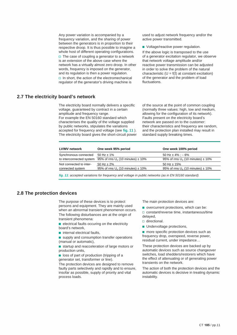
The electricity board normally delivers a specificvoltage, guaranteed by contract in a certainamplitude and frequency range.For example the EN 50160 standard whichcharacterises the quality of the voltage suppliedby public networks, stipulates the variationsaccepted for frequency and voltage (see fig. 11 ).The electricity board gives the short-circuit power
of the source at the point of common coupling(normally three values: high, low and medium,allowing for the configuration of its network).Faults present on the electricity board’snetwork are passed on to the customer:their characteristics and frequency are random,and the protection plan installed may result instandard supply breaking times.
2.8 The protection devices
The purpose of these devices is to protectpersons and equipment. They are mainly usedwhen an abnormal transient phenomenon occurs.The following disturbances are at the origin oftransient phenomena:c electrical faults occuring on the electricityboard’s network,c internal electrical faults,c supply and consumption transfer operations(manual or automatic),c startup and reacceleration of large motors orproduction units,c loss of part of production (tripping of agenerator set, transformer or line).The protection devices are designed to removefaulty parts selectively and rapidly and to ensure,insofar as possible, supply of priority and vitalprocess loads.
The main protection devices are:
c overcurrent protections, which can be:v constant/reverse time, instantaneous/timedelayed,v directional.
c Undervoltage protections,
c more specific protection devices such asfrequency drop, overspeed, reverse power,residual current, under impedance…
These protection devices are backed up byautomatic devices such as source changeoverswitches, load shedders/restorers which havethe effect of attenuating or of generating powertransients on the network.
The action of both the protection devices and theautomatic devices is decisive in treating dynamicinstability.
LV/MV network
Synchronous connected to interconnected system
Not connected to inter-connected system
One week 95% period
50 Hz ± 1%95% of rms Un (10 minutes) ± 10%
50 Hz ± 2%95% of rms Un (10 minutes) ± 10%
One week 100% period
50 Hz ± 4% ; – 6%95% of rms Un (10 minutes) ± 10%
50 Hz ± 15%95% of rms Un (10 minutes) ± 10%
fig. 11 : accepted variations for frequency and voltage in public networks (as in EN 50160 standard).

CT 185 / pp.12
2.9 The network as a whole
Overall network behaviour is the result of theindividual behaviour of each of its components,including protection and monitoring/controlequipment, and of their interactions.
c Static stability defines the power flows in thenetwork for all normal operating modes of theindustrial site (configuration of the network andproductions in progress). In each case the« voltage operating schedule » specifies theactions to be performed to keep voltage withinacceptable limits (e.g. better than 3%) and tominimise losses for:v power delivered by the sources,v adjustment of transformer taps,v compensation capacitors.
c Dynamic stability constraints condition networkevolution according to operating modes andincidents, as well as the actions to be taken tominimise risks and disturbances to the process.
Note that monitoring and control plays animportant role in both normal and abnormaloperation of the network in that it providesknowledge at all times of generator power flows,voltage and load.
At this level the complexity of the global problemis far greater than that of a « static » state.Dynamic stability studies are then used torecommend the most appropriate measures tobe taken and solutions to be implemented foreach individual case.
The purpose of this chapter is to provide generalinformation on the objectives assigned to thestudies and on the study content, with particularemphasis on the causes, effects and solutions of
dynamic instabilities. Finally a study conductedby the « Electrical System Analysis »Department will be presented as an example.
3.1 General
Study objectives
Dynamic stability studies consist of analysingand acquiring prior knowledge of the variations intime of electrical quantities at various points of anetwork, and of the changes in the mechanicalparameters of rotating machines as a result ofsudden disturbances.
The purpose of these studies is to find:
c the network operating conditions able toensure proper continuity of load supply,
c the maximum available power when adisturbance occurs,
c the optimum adjustment values of theprotection system components,
c the load shedding plan to ensure supply ofvital loads,
c the best machine regulation adjustments.
Each study is based on a specific casedepending on:c types of sources,c types of loads,c network architecture,c network operating mode,c the instability causes taken into account.
There are various reasons for studying dynamicstability:c preventive study when designing a network,c addition of high power generators and/orloads on an existing network,c curative study when an incident occurs.
If the study is conducted before the installation isproduced, these factors can be modified for themost part. Operators can thus be certain that intransient modes, the behaviour of the network
3 Dynamic stability study of industrial networks
CT 185 / pp.13
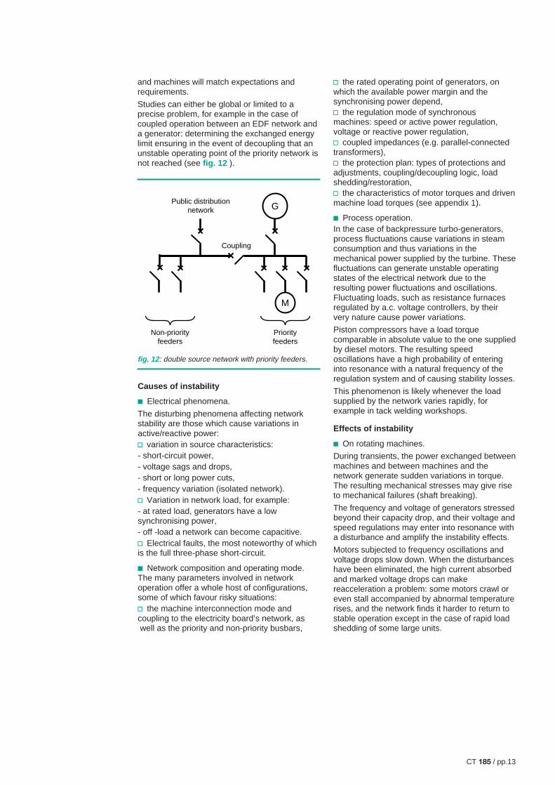
G
M
Public distribution network
Coupling
Non-priority feeders
Priority feeders
and machines will match expectations andrequirements.
Studies can either be global or limited to aprecise problem, for example in the case ofcoupled operation between an EDF network anda generator: determining the exchanged energylimit ensuring in the event of decoupling that anunstable operating point of the priority network isnot reached (see fig. 12 ).
fig. 12 : double source network with priority feeders.
Causes of instability
c Electrical phenomena.
The disturbing phenomena affecting networkstability are those which cause variations inactive/reactive power:v variation in source characteristics:- short-circuit power,- voltage sags and drops,- short or long power cuts,- frequency variation (isolated network).v Variation in network load, for example:- at rated load, generators have a lowsynchronising power,- off -load a network can become capacitive.v Electrical faults, the most noteworthy of whichis the full three-phase short-circuit.
c Network composition and operating mode.The many parameters involved in networkoperation offer a whole host of configurations,some of which favour risky situations:v the machine interconnection mode andcoupling to the electricity board’s network, as well as the priority and non-priority busbars,
v the rated operating point of generators, onwhich the available power margin and thesynchronising power depend,v the regulation mode of synchronousmachines: speed or active power regulation,voltage or reactive power regulation,v coupled impedances (e.g. parallel-connectedtransformers),v the protection plan: types of protections andadjustments, coupling/decoupling logic, loadshedding/restoration,v the characteristics of motor torques and drivenmachine load torques (see appendix 1).
c Process operation.In the case of backpressure turbo-generators,process fluctuations cause variations in steamconsumption and thus variations in themechanical power supplied by the turbine. Thesefluctuations can generate unstable operatingstates of the electrical network due to theresulting power fluctuations and oscillations.Fluctuating loads, such as resistance furnacesregulated by a.c. voltage controllers, by theirvery nature cause power variations.
Piston compressors have a load torquecomparable in absolute value to the one suppliedby diesel motors. The resulting speedoscillations have a high probability of enteringinto resonance with a natural frequency of theregulation system and of causing stability losses.
This phenomenon is likely whenever the loadsupplied by the network varies rapidly, forexample in tack welding workshops.
Effects of instability
c On rotating machines.
During transients, the power exchanged betweenmachines and between machines and thenetwork generate sudden variations in torque.The resulting mechanical stresses may give riseto mechanical failures (shaft breaking).
The frequency and voltage of generators stressedbeyond their capacity drop, and their voltage andspeed regulations may enter into resonance witha disturbance and amplify the instability effects.
Motors subjected to frequency oscillations andvoltage drops slow down. When the disturbanceshave been eliminated, the high current absorbedand marked voltage drops can makereacceleration a problem: some motors crawl oreven stall accompanied by abnormal temperaturerises, and the network finds it harder to return tostable operation except in the case of rapid loadshedding of some large units.

CT 185 / pp.14
c On the network.The power oscillations responsible for very highcurrents in the connections and transformerscause temperature rises which seriously affectequipment withstand.
Voltage drops resulting from the high currents,cause malfunctioning of certain sensitivedevices (e.g. contactors, electronicequipment…). Disconnection of one or moregenerators destroys the consumption/productionbalance and may cause total collapse of thenetwork.
Mastering instabilityA number of measures can be taken to preventthe instability limit from being crossed:when these measures are taken at generator,network or load level, they either preventinstability or help fight against it effectively rightfrom the start.
c At generator level:The use of generator sets with very highmechanical inertia reduces the effect of loadvariations.The adjustment parameters of the variousregulations give response speed choices wellsuited to the disturbances considered.Choice of generator operating point is important:power margin available on request,synchronising power potential.
c At network level.v All measures tending to decrease impedancesof tie lines increase the chances of returning to astable state after an incident,v redundancy of sources and the possibility ofshedding non-priority loads, minimises theduration and depth of voltage sags. Loadshedding/restoration by power step preventsmajor disturbances.v Rapid, selective elimination of the short-circuited part of the network limits harmfulconsequences for the network (rapid-action,limiting circuit-breakers).v The protection plan must take account ofthe various instability scenarios (choice andadjustment of protection devices, use of logicdiscrimination instead of time discrimination).v Tripping by separate phase in order toeliminate single-phase faults in transmissionnetworks, and use of shunt circuit-breakersfor MV distribution networks, have beneficialeffects on factory network stability.
c At load level.v Use of « starters » to attenuate the motorenergising current,v implementation of undervoltage anddirectional protection devices and transitmonitoring of powers for large motors,v monitoring loads with cyclic or intermittentoperation.
3.2 Stability studies
Positioning the problemWe remind you that the dynamic stability of anetwork is the capacity of this network to resumenormal operation after a sudden disturbance.A stability study thus consists of analysing theelectrical and mechanical behaviour of machinesfrom the time when the disturbance appears tothe time when, the disturbance having beeneliminated, the network returns or fails to returnto normal operating conditions. The problem is athree-fold one:c Electrical: involving the standard networkequations (Kirchoff’s laws) where the machinesare represented by Park’s equations enablingtheir transient states to be studied.
c Dynamic of the variations around a state ofequilibrium involving the speed and excitationregulation transfer functions.
c Mechanical as we need to know whether ornot machine speed is maintained; themechanical equations of each machine
J dωdt
= Cm – Cr take account of the moment
of inertia J and the characteristics of load andmotor torque.
Calculation methods usedc Analytical method.In simple network cases, i.e. networks containingonly one machine (possibly two) and passiveloads, the analytical description of machineparameter evolution if a fault occurs is feasible.This analysis is possible in cases where speedcan be considered constant. The machineequations describe their behaviour in sufficientdetail even if some parameters are overlooked.

CT 185 / pp.15
The various methods of analysis (Behn-Eschengurg, Potier’s diagram, Blondel’sdiagram) enable knowledge of the efficiency,excitation current and voltage drops ofgenerators and motors. Park’s transformationapplied to machines enables both steady andtransient states to be analysed.
c Digital simulation.
This method is the one universally used today.A computer digitally solves the equationsystems describing network behaviour. Theincreasing power of microcomputers nowenables large networks to be simulated inreasonable times and fine analyses of thebehaviour of machines and network componentsto be considered. As all loads and generatorscontribute to operation of the whole and interactwith one another, the problem is a large-scaleone and if we are to remain within a rangecompatible with microcomputer capacity, datamust be simplified so as to represent only a fewdozen machines:v by grouping passive loads,v by grouping motors as « equivalent motors »with identical behaviour,v by grouping generators in the same way,v by comparing a very powerful source withrespect to the powers studied, with a perfectsource in series with an impedance.
These calculation preliminaries are obviouslyvital as they define the assumptions which mustbe reasonably complex and representative ofreality.
The resolution method chosen is a stepwise onetaking account of:v slowly varying quantities: motor torque,relative rotor speed, inductor winding flux,excitation voltage,v rapidly varying quantities: currents andvoltages in the various network branches and thevarious machine circuits, voltage at the machineterminals and power delivered.
This method is implemented by a softwaredesigned to treat all types of industrial networks,such as for example the MG-STAB calculationcode developed by Schneider.
Developing a study
A stability study follows a certain logic and isbroken down into a number of steps describedbriefly below:
c The calculation preliminaries.
As result accuracy is directly linked to theexactitude of network data, the study begins bycollecting these data and thus looks for the exactnumerical values of the network componentcharacteristics.Modelling then consists of quantitativelydescribing the physical laws governing operationand interconnection of network components inthe form of a data file.
Calculation of the initial state of load flows isdetermined by the computer whose specificstability programme processes the data file:voltages at nodes, currents and powers inbranches, sources and loads, machine operatingpoints.
c The simulations.
Network topology and components vary fromone study to another. Types of disturbances arenumerous and the point of application variable.
In the light of the diagram studied, the specialistwill select the disturbances and their applicationpoint according to how critical the problem is.
The points considered are normally undervoltageon the electricity board’s network, short-circuits(medium voltage, sources), partial supply losses(lines, transformers, generators), starting of largemotors and effects on electrical energy ofimportant process phenomena.
Calculations of dynamic state in time, allowingfor the disturbances considered, reproduce theexpected real reactions of the network and theactions to be taken. The various scenarios areplayed through in order to treat all the chosencases and sensitivity to parameters.
c The results.
Results are given mainly by curves changing intime: voltages on the various busbars, currentsin feeders, power flows, machine data (speed,electrical and mechanical torque, excitation),regulation of excitations and mechanical drivedevices.
In short the results concern operation of theelectrical system in disturbed operatingconditions and enable:v verification of stability,v knowledge of potential backup capacity on afault,v confirmation of the protection plan,v adjustment of the regulations.

CT 185 / pp.16
3.3 Study example
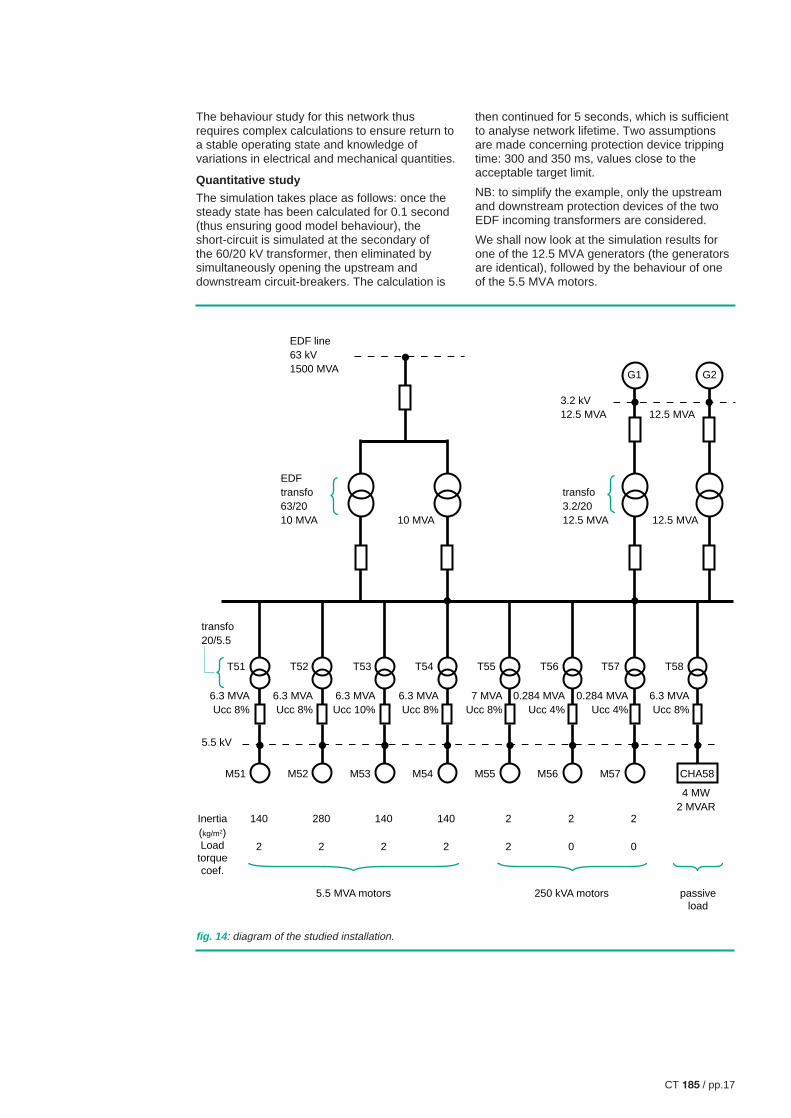
The case described below is taken from a realstudy of a standard heavy industry industrialnetwork. The aim is to study the impact of ashort-circuit at the secondary of a 63/20 kVtransformer (see fig. 13 ).
Description of the networkThe network contains (see fig. 14 ):c A 63 kV EDF source delivering on the 20 kVbusbar of the factory through 63/20 kVtransformers.c An autonomous source made up of twocouplable generators delivering on the 20 kVthrough 3.2/20 kV transformers.c Asynchronous motors supplied in 5.5 kVthrough 20/5.5 kV transformers connected onthe 20 kV network, on priority or non-prioritybusbars: some of these motors are equivalentmachines.c An equivalent passive load representing allthe other factory loads on the priority busbar.
The protection devices considered in thisexample are overcurrent, directional ones,applied to the network transformers.
Objective of the studyv Study assumption:A full three-phase short-circuit occurs on thesecondary of one of the two EDF 63/20 kVsupply transformers (see fig. 13 ).v Undesirable event:The fault must not cause the loss of the 5.5 MWmotors.v Question to be solved:What is the maximum acceptable faultelimination time if dynamic instability is to beavoided?
The qualitative description of phenomena, for thescenario considered, is as follows:c When the fault occurs, voltage at the short-circuit point and on the entire 20 kV commonbusbar is zero (negligible coupled impedances).The power supplied by the generator sets movesfrom the initial value to a very low value due tolosses in the step-up transformers: loadshedding decrease of active power results inacceleration of the generators which continue tobe driven by the turbines whose mechanicalregulations do not immediately react. At thesame time the voltage regulation will raiseexcitation current to its maximum value to try tocompensate the undervoltage.The motors deliver in the short-circuit in the firstphase of the transient state until the flux dies out.Then absence of motor torque, due to very lowvoltage, causes a deceleration.
EDF
non-priority priority
G1 G2
S. C.
F O
F O
fig. 13 : studied configuration.
The electricity board’s network supplies a currentcorresponding to its short-circuit power in serieswith the parallel-connected transformers.c The overcurrent directional protection deviceswill eliminate the only faulty transformer.c On elimination of the fault, voltage is restoredat the 20 kV busbar. Its value depends on thecombined action of the EDF network, themaximum overexcitation generators and the loadcurrent inrush. The generators are no longereither in phase with one another or with thenetwork (in fact each source has evolvedseparately from the others as voltage wasvirtually zero) and their speeds are different. Thepower they supply is low as turbine energysupply has been reduced by the regulators andthey will slow down. The motors have sloweddown, the rotor field is shifted with respect to thestator field produced by the network, and theirspeeds are different. The inrush current is of theorder of magnitude of the starting current, a factwhich causes serious voltage drops in theconnections as all motors try to reaccelerate atthe same time.c Oscillating energy exchanges then take placebetween the various machines via the networkconnections and transformers. If the generatorspeed deviations, which are at the origin of thesetransient phenomena, decrease, normaloperating conditions are resumed. Otherwise thesynchronous machines fail to recover theirsynchronism and fall out of step. Theasynchronous motors stall or crawl.
CT 185 / pp.17
EDF line63 kV1500 MVA
3.2 kV12.5 MVA
transfo20/5.5
12.5 MVA
EDFtransfo63/2010 MVA
transfo3.2/2012.5 MVA 12.5 MVA10 MVA
G1 G2
M51 M52 M53 M54 M55 M56 M57
140
2
280
2
140
2
140
2
2
2
2
0
2
0
passive load
250 kVA motors5.5 MVA motors
CHA58
T51
6.3 MVAUcc 8%
5.5 kV
Inertia(kg/m2)Load
torque coef.
6.3 MVAUcc 8%
6.3 MVAUcc 10%
6.3 MVAUcc 8%
7 MVAUcc 8%
0.284 MVAUcc 4%
0.284 MVAUcc 4%
6.3 MVAUcc 8%
4 MW2 MVAR
T52 T53 T54 T55 T56 T57 T58
fig. 14 : diagram of the studied installation.
The behaviour study for this network thusrequires complex calculations to ensure return toa stable operating state and knowledge ofvariations in electrical and mechanical quantities.
Quantitative study
The simulation takes place as follows: once thesteady state has been calculated for 0.1 second(thus ensuring good model behaviour), theshort-circuit is simulated at the secondary ofthe 60/20 kV transformer, then eliminated bysimultaneously opening the upstream anddownstream circuit-breakers. The calculation is
then continued for 5 seconds, which is sufficientto analyse network lifetime. Two assumptionsare made concerning protection device trippingtime: 300 and 350 ms, values close to theacceptable target limit.
NB: to simplify the example, only the upstreamand downstream protection devices of the twoEDF incoming transformers are considered.
We shall now look at the simulation results forone of the 12.5 MVA generators (the generatorsare identical), followed by the behaviour of oneof the 5.5 MVA motors.

CT 185 / pp.18
c Generator.
v Examination of active power (see fig. 15 )As soon as the fault appears, the active powersupplied by the generator decreases markedlyand continues to decrease throughout theduration of the fault.Once the fault has been eliminated, an activepower oscillation occurs which is the result of theexchanges between this generator, the othergenerator and the EDF source. This powerexchange corresponds to the power required to
restore synchronism between generator andnetwork voltage. If the protection devices tripwithin 300 ms (the fault is removed 40 ms later),the power oscillations quickly decrease andsettle at the initial value. In the second case,however, the oscillations continue withoutshowing any sign of decreasing, and thegenerator is unable to resynchronise.
v Examination of reactive power (see fig. 16 ).When the fault appears, the reactive powerincreases markedly and is maintained at a high
fig. 16 : evolution of reactive power of one ofthe 12.5 MVA generators.
a - Tripping of protection devices in 300 ms
b - Tripping of protection devices in 350 ms
0
fault
1 2 3 4 5 6
sec
0
-5
-10
5
10
15
20
MVA
0
fault
1 2 3 4 5 6
0
-5
-10
5
10
15
20
MVA
sec
fig. 15 : variations in active power of one ofthe 12.5 MVA generators.
a - Tripping of protection devices in 300 ms
b - Tripping of protection devices in 350 ms
0
fault
1 2 3 4 5 6
sec
0
-10
-20
20
10
MW
0
fault
1 2 3 4 5 6
0
-10
-20
20
10
MW
sec

CT 185 / pp.19
value throughout the duration of the fault. Thereactive power which had settled at roughly2.7 times the value before the fault, continues toincrease after elimination of the fault due to thereturn to a value close to normal voltage value.The reactive power peak corresponds to themagnetisation needs of the network loads.
v Examination of speed (see fig. 17 ).Speed increases when a short-circuit occurs asa consequence of the power load sheddingobserved (low U!).
Elimination of the fault causes deceleration ofthe generator, and its speed begins to oscillate.If the protection devices trip only after 350 ms(see fig. 17b ), the generator is unable toresume a stable operating state.
v Examination of voltage (see fig. 18 ). If theprotection devices trip after 300 ms (see fig. 18a ),voltage is quickly restored to rated value afterelimination of the fault. However, voltage is notrestored and even tends to drop if the protectiondevices trip only after 350 ms (see fig. 18b ).
fig. 17 : evolution of speed of one of the 12.5 MVAgenerators.
a - Tripping of protection devices in 300 ms
b - Tripping of protection devices in 350 ms
fig. 18 : evolution of voltage at the terminals of one ofthe generators.
a - Tripping of protection devices in 300 ms
b - Tripping of protection devices in 350 ms
0
fault
1 2 3 4 5 6
sec
1
1.05
0.95
Ω—Ω0
Ω—Ω0
0
fault
1 2 3 4 5 6
1
1.05
0.95
sec
0
fault
1 2 3 4 5 6
sec
3000
2000
1000
V
0
fault
1 2 3 4 5 6
3000
2000
1000
V
sec

CT 185 / pp.20
v Evolution of current (see fig. 19 ).In the same manner as voltage, if the protectiondevices trip after 300 ms, current returns to theinitial value (see fig. 19a ). However it remains ata high average value if the devices trip only after350 ms (see fig. 19b ).
The generator protection devices mustdisconnect the generator in the event of tripping
fig. 19 : evolution of the current delivered by one of thegenerators.
a - Tripping of protection devices in 300 ms
b - Tripping of protection devices in 350 ms
after 350 ms, which does not allow correctoperation of the installation.
c Behaviour of a representative motor (see fig. 20 ).
Behaviour of motors during two calculations(tripping of protection devices after 300 ms or350 ms) is also representative of the instabilityobserved when tripping time is too long. Whenthis time is 350 ms, the speed of the motor
fig. 20 : evolution of motorspeed.
a - Tripping of protection devices in 300 ms
b - Tripping of protection devices in 350 ms
0
fault
1 2 3 4 5 6
sec
2000
6000
4000
8000
A
0
fault
1 2 3 4 5 6
2000
6000
4000
8000
A
sec
0
fault
1 2 3 4 5 6
sec0.80
1
0.95
0.90
0.85
Ω—Ω0
Ω—Ω0
0
fault
1 2 3 4 5 6
0.85
0.80
0.90
0.95
1
sec
CT 185 / pp.21
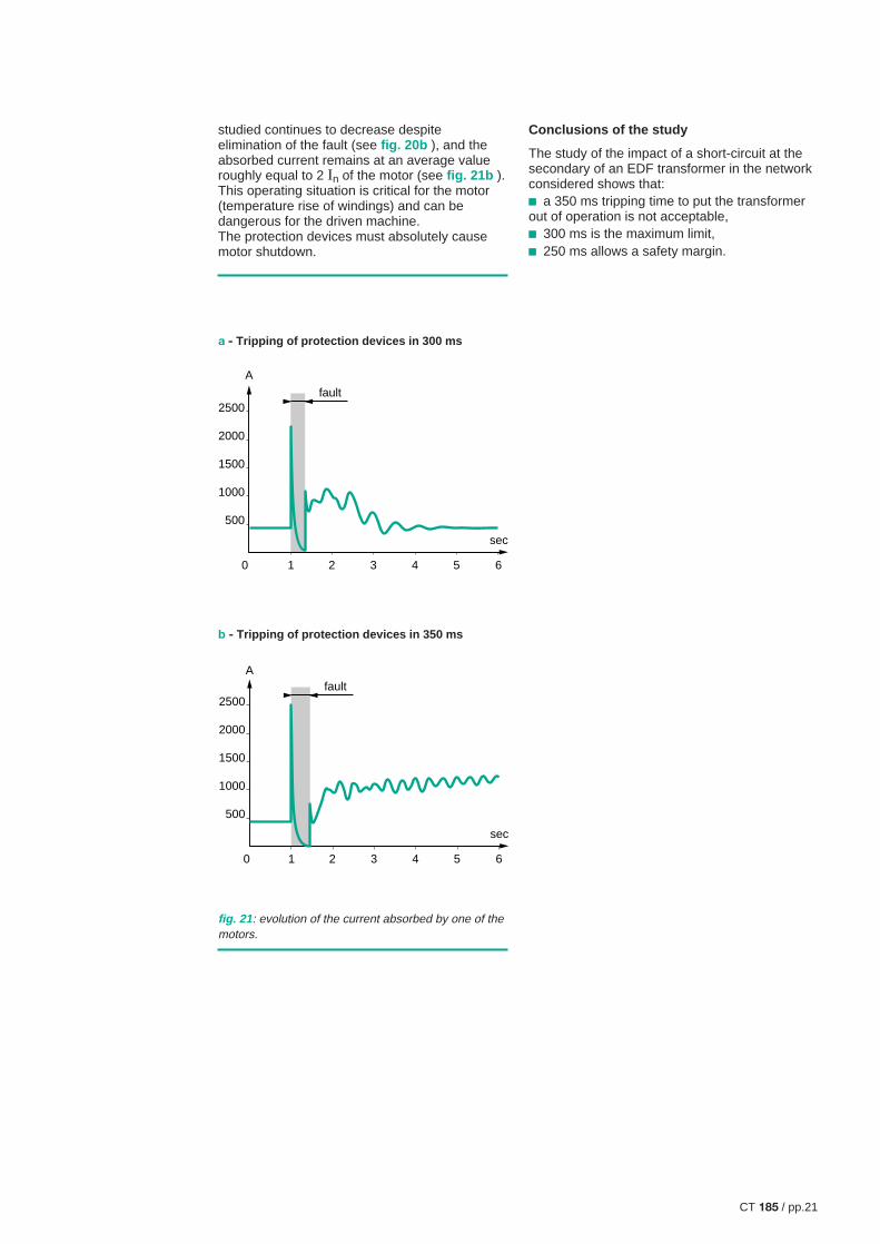
studied continues to decrease despiteelimination of the fault (see fig. 20b ), and theabsorbed current remains at an average valueroughly equal to 2 In of the motor (see fig. 21b ).This operating situation is critical for the motor(temperature rise of windings) and can bedangerous for the driven machine.The protection devices must absolutely causemotor shutdown.
fig. 21 : evolution of the current absorbed by one of themotors.
a - Tripping of protection devices in 300 ms
b - Tripping of protection devices in 350 ms
0
fault
1 2 3 4 5 6
sec
500
1000
1500
2000
2500
A
0
fault
500
1000
1500
2000
2500
1 2 3 4 5 6
A
sec
Conclusions of the study
The study of the impact of a short-circuit at thesecondary of an EDF transformer in the networkconsidered shows that:c a 350 ms tripping time to put the transformerout of operation is not acceptable,c 300 ms is the maximum limit,c 250 ms allows a safety margin.

CT 185 / pp.22
These studies have their use both in the designof new networks and upgrading existingnetworks. In many cases they are necessary forthe establishment of the protection plan and areinteractive with implementation of modernnetwork monitoring and control systems.
Nowadays dynamic stability studies are mainlyconducted on high performance microcomputersby means of specialised softwares some ofwhich are available on the market. Use of suchsoftware, if it is to be effective, is howeverreserved for experienced specialists.
These studies take on tremendous proportions inthe case of complex, large-sized networks wherethere are very many possibilities to examine.However they can be used to equal advantageon precise cases or simple installations.
The development of new contracts proposed byelectricity boards and cogeneration (privateproduction) points towards many potentialnetwork studies.
4. Conclusions
A network is a set of interconnected electricalenergy production and consumption devices.
The electrical state of a network is the result ofall the interactions of its various components.Changes to this state, inherent in network life(process operation, electrical incidents) naturallycause the network to move to a new state whichmay or may not be stable.
In the latter case (instability in transient state),loss of energy, at least partial and sometimeseven total (resulting in network collapse) occurs.For industrial firms this can result in extremelycostly production losses, destruction of electricaland process equipment, not to mention risks foroperating staff.
This Cahier Technique highlights the advantagesof dynamic stability studies whose purpose is topredict the behaviour of electrical networks.Solutions can thus be recommended to avoidinstability states, thereby optimising availability ofelectrical energy.

CT 185 / pp.23
N N N
C
Type 1
Motor torque shapes
N N N
Type Aconstant
Type Bparabolic
Type Cnegligible
Type Dwith high break-away
N
C
Cn
C
Cn
Valveopen
Valveclosed
C
Cn Cn
C
Load moment shapes
Type 2 Type 3 Type 4
N
C C C
Curve almost flat between Cd and Cmaxi
Types of rotor:simple cage with deep slots and fine barssimple cage with trapezoidal, L-shaped or T-shaped slot
centrifugal compressorscentrifugal pumpsaxial-flow pumpspropeller pumpsfans, turbines
piston compressors, lifting and handling machines,conveyor belts, grinding mills
generating machines of converter sets
grinding mills, crushers(after adjustment)
Curve increasing between Cd and Cmaxi
simple cage
Curve with sag between Cd and Cmaxi
simple cage with trapezoidal, L-shaped or T-shaped slots.double cage
Curve decreasing Cd = Cmaxi
rotor with high slipping
Motor torque must be adapted to the load torqueof the load, from shutdown right through to ratedspeed.For example, the association of a motorcomplying with curve 2 and of a load complyingwith curve B, is correct.
Appendix 1: starting of asynchronous cage motors
Some configurations must be banned. Theassociation 2-A or 2-D requires considerablemotor oversizing, and 1-A or 1-D is to bepreferred.

CT 185 / pp.24
Appendix 2: bibliography
Standardsc CENELEC EN 50160: characteristics of thevoltage supplied by public distribution networks.
Cahiers Techniquesc Analyse des réseaux triphasés en régimeperturbé à l’aide des composantes symétriques,Cahier Technique no 18, December 1990 -B. DE METZ NOBLAT
c MV public networks throughout the world,Cahier Technique no 155, february 1992 -CH. PURET
c Control, monitoring and protection of HVmotors,Cahier Technique no 165, May 1995 -J.Y. BLANC
c Automatic transfering of power supplies in HVand LV networks,Cahier Technique no 161, March 1996 -G. THOMASSET
c HV industrial network design,Cahier Technique no 169, October 1994 -G. THOMASSET
c Protection of industrial and tertiary MVnetworks,Cahier Technique no 174, June 1996 -A. SASTRÉ
Miscellaneous documents
c Guide de l’ingénierie électrique des réseauxd’usines,G. SOLIGNAC,Electra, Lavoisier Tec et Doc.
c Electrotechnique Industrielle,G. SEGUIER and F. NOTELET,Technique et documentation.


Schneider Direction Scientifique et Technique,Service Communication TechniqueF-38050 Grenoble cedex 9Fax: (33) 04 76 57 98 60
Design: AXESS - Saint-Péray (07).Photos: Merlin Gerin et Telemecanique.Printing: Clerc Fontaine - 1500.- 100 FF- ©
199
7 S
chne
ider
06-9783332