Embed Size (px)
Citation preview
Cage Suspension Gear in Indian Coal mines
SRI J. P. GOENKA B.Sc. (Min. Engg.) Hons A.I.S.M. F.I.E., M.M.G.I.
This paper was read by Sri J. P. Goenka, Nanda Millar Co. at the workshop on
“Safety & Maintenance of Winding Engine Installations” organized by
Directorate General of Mines Safety, Ministry of Labour, Government of India,
Eastern Zone, Sitarampur on 9th Oct’07 at Kunstoria-ECL.
We are grateful to Sri S. Puri, Dy. Director General of Mines safety, DGMS
Eastern Zone. Sitarampur & ‘Sri G. N. Venktesh Director of Mines safety
(Mech). for inviting us to present this paper.
SYNOPSIS
The paper reviews the various type of rope attachments including
Friction Wedge Rope Cappel, White Metal Cappel, Safety Hook & C. S.
Gear.
It describes the manufacture of these equipments including type of
steel that are permitted by DGMS for manufacture Limits of permissible
imperfections has been described.
Norms of discard, Inspection schedule & Installation instruction are
detailed.
Finally the author has emphasized on the adoption of ISO 9001-2000
by manufacturer. Grit blasting of C.S. Components & use of Hydraulic
Rope Cappel Banding Machine by the Industry has been advocated.
1

Steel rope was introduced in our coal mines in the beginning of 20th century Prior to that Hemp rope or Flat chains were used for winding.
With the introduction of steel wire ropes, demand for rope end attachments arose.
If required collaborative efforts of manufacturers, users, mining officials of statutory authorities to envolve attachments which are safe and reliable.
CAGE SUSPENSION GEAR IN INDIAN COAL MINES
In Drum Winding general requirements can be taken as follows :-
l
l Incroporation of a safety device.
l Four-point suspension of the cage.
l Free movement of the gear in two planes.
Method of connecting winding rope to suspension gear. White Metal Socket or Friction Wedge Rope cappel are usually used for this purpose.
White Metal Socket-solid machined with open jaws are widely used for
connecting the winding rope to the suspension. The mouth of the socket is
rounded to prevent the damage to the rope and short length of parallel bore is
provided next to the mouth. After carefully preparing and securely binding the
rope with soft iron, seizing wire, anti-friction bearing alloy is poured into the
socket (IS 3937 Part 2). A properly carried out capping of the rope in the socket
will withstand the breaking strength of the rope.
The length of taper of the socket is usually not less than six times and not more 0than eight times the diameter of the rope. The angle of the taper is between 3
0and 6 .
Method of connecting winding rope to suspension gear.
WHITE METAL ROPE CAPPEL
Fig - 1
CAGE SUSPENSION FOR DRUM WINDING
2
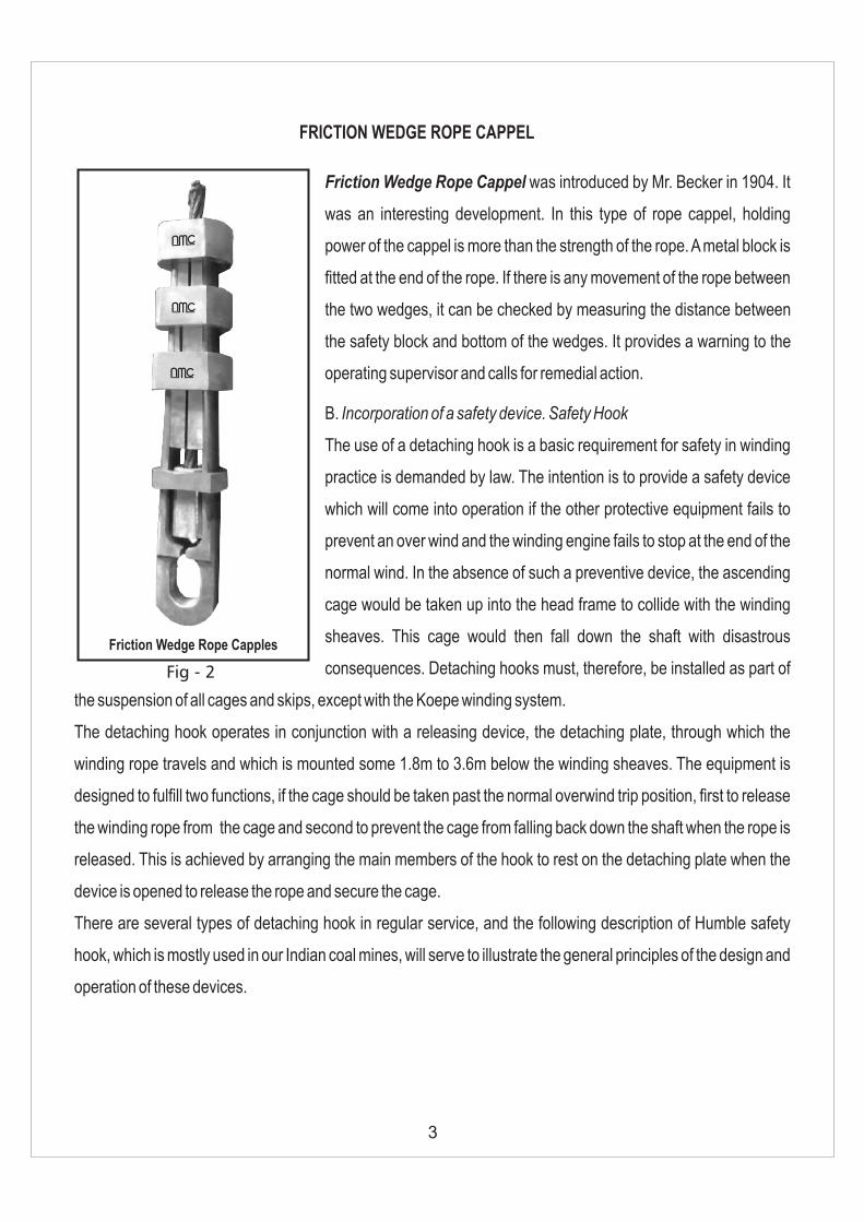
Friction Wedge Rope Cappel was introduced by Mr. Becker in 1904. It
was an interesting development. In this type of rope cappel, holding
power of the cappel is more than the strength of the rope. A metal block is
fitted at the end of the rope. If there is any movement of the rope between
the two wedges, it can be checked by measuring the distance between
the safety block and bottom of the wedges. It provides a warning to the
operating supervisor and calls for remedial action.
B. Incorporation of a safety device. Safety Hook
The use of a detaching hook is a basic requirement for safety in winding
practice is demanded by law. The intention is to provide a safety device
which will come into operation if the other protective equipment fails to
prevent an over wind and the winding engine fails to stop at the end of the
normal wind. In the absence of such a preventive device, the ascending
cage would be taken up into the head frame to collide with the winding
sheaves. This cage would then fall down the shaft with disastrous
consequences. Detaching hooks must, therefore, be installed as part of
the suspension of all cages and skips, except with the Koepe winding system.
The detaching hook operates in conjunction with a releasing device, the detaching plate, through which the
winding rope travels and which is mounted some 1.8m to 3.6m below the winding sheaves. The equipment is
designed to fulfill two functions, if the cage should be taken past the normal overwind trip position, first to release
the winding rope from the cage and second to prevent the cage from falling back down the shaft when the rope is
released. This is achieved by arranging the main members of the hook to rest on the detaching plate when the
device is opened to release the rope and secure the cage.
There are several types of detaching hook in regular service, and the following description of Humble safety
hook, which is mostly used in our Indian coal mines, will serve to illustrate the general principles of the design and
operation of these devices.
FRICTION WEDGE ROPE CAPPEL
Friction Wedge Rope Capples
Fig - 2
3

The detaching hook consists of four plates; the two outer
plates fixed together by rivets passing through a V-shaped
spacing blocking at the lower and two inner plates shaped like
a hook at their upper ends. The inner plates are connected
together scissor-wise and to the outer plates by the hinge pin
at the centre. The lower end of each inner Plate is shaped to
provide the striking horn and the notched projection for resting
on catch plate in the event of an overwind. The inner plates
have an extra thickness of material in the hook region. With
this type of hook, both the inner (hook) plates and the outer
(containing) plates are load bearing. The inner plate transmit
the load from the top connecting shackle pin to the hinge pin
from which point the outer plates transmit the load to the lower
shackle pin. The hook is prevented from opening during
winding by a shear pin made of copper which is sheared as the
hook is drawn through the catch plate.
C. Four point suspension of the cage.
To achieve even suspension of the cage, distribution plate is fitted below the adjusting device and from the plate
chains are attached by means of shackles. Four corner, chains, identical in length are fitted to the cage hangers
by shackles and two safety chains are provided where safe working load is 8 tons or more. These being attached
vertically from the distribution plate to the top of the cage. Sufficient slack is allowed to ensure that they do not
carry the load.
D. Free movement of gear in two planes.
Free movement of the suspension gear in two planes is allowed by the connection used between the various
component parts of the suspension gear.
In our system, rope cappel in directly connected to the top shackle of the safety hook. Bottom shackle of the safety
hook is connected to the top shackle of the distribution plate. By this type of connection we can have free
movement of cage suspension gears in two planes.
‘Humble’ type safety Hook
Fig - 3
4

l Manufacturer must have adequate manufacturing and forging facilities.
l All plate and section and bars shall be well and cleanly rolled to the dimensions specified and shall be
sound and free from flaws, laminations, cracks or other defects.
l Material of construction : C.S. Gear shall be manufacture from any of the following type of steels.
l Heat Treatment : All components of C.S. Gear after manufacture shall be heat treated to get optimum
mechanical properties. The components shall be either normalized or normalized and tempered, or hardened
and tempered, or refined and hardened and tempered.
l Testing and examination : the manufacturer shall have suitable arrangement for examination at every
stage of manufacture to ensure quality of product. The tesing personnel for carrying out non-destructive testing
such as particle flaw detection and ultrasonic flaw detection shall have NDT level II competency certificate
issued by a trainning institute recognized by the statutory authority.
l Proof Load test : of each finished component of suspension gear separately or collectively, shall be
subjected to tensile proof load three times the safe working load and it shall satisfactorily withstand the test
without any permanent deformation or defects. Each component shall be examined for cracks after proof load
test and visually by means of magnetic crack detection and ultrasonic tests. Permissible imperfection for
magnetic particle inspection are given below.
1 .Magnetic particle flaw detection shall be carried out as per IS 3703 :
The type of defects and their limits are given in Fig. 4 to Fig. 12.
2. Imperfections in components may be in the form of :
A) Non-metallic inclusions which are inherent in steels, and
B) Cracks.
Note - Magentic particle inspection will reveal these imperfections when they are on or just below the surface.
3) Limits of Permissible Imperfections :
The Limits of Permissible inclusions shall be as given in Fig. Cracks shall not be permitted.
A) A Longitudinal imperfection is one which generally runs parallel to the major dimension of the component, a
MANUFACTURE OF C. S. GEAR
5
C% Si% Mn% Ni% Cr% Mo%
20Mn2.15 to
.25
.15 to
.35
1.3 to
1.7
20Ni2Cr2Mo2
(SAE8620).18 to
.23
.2 to
.35
.7 to .9 .40 to
.70
.40 to
.60
.15 to
.25
— — —
— — —
—

PIN AND NUT
Part Type of Imperfection Permissible Imperfections
Shaded Areas
Transverse None
Longitudinal None>32 mm
Unshaded Areas
Pin, barrel andthread
Pin headand nut
Transverse None>10 mm
Longitudinal None>10 mm
All dimensions in millimeters.
FIG. 4 PIN AND NUT
transverse imperfection is one which runs at right angles to the line defined for a longitudinal imperfection.
B) Record : Imperfections which, although within the permissible limits, are of a large number, unusual pattern or
direction, should be recorded on the component certificate.
6
TRANSVERSE
LONGITUDINAL
TRANSVERSE
LONGITUDINAL

SHACKLE BODY
Part Type of Imperfection Permissible Imperfections
Shaded Areas
Shackle bodyTransverse None
Longitudinal None>10 mm
Unshaded Areas
Shackle bodyTransverse None
Longitudinal None>32 mm
All dimensions in millimeters.
FIG. 5 SHACKLE BODY
All dimensions in millimeters.
FIG. 6 CHAIN LINKS
Part Type of Imperfection Permissible Imperfections
All Areas
Chain linkTransverse None
Longitudinal None>10 mmElectrode Burns None
7
TRANSVERSELONGITUDINAL
090
TRANSVERSE
26
LONGITUDINAL
ELECTRODE BURNS
TRANSVERSE
CHAIN LINKS
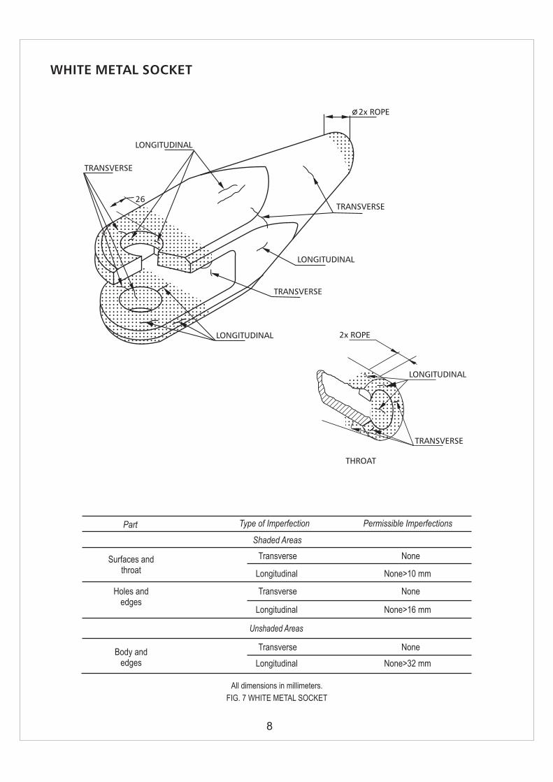
WHITE METAL SOCKET
Part Type of Imperfection Permissible Imperfections
Shaded Areas
Surfaces andthroat
Transverse None
Longitudinal None>10 mm
Holes andedges
Transverse None
Longitudinal None>16 mm
Unshaded Areas
Body andedges
Transverse None
Longitudinal None>32 mm
All dimensions in millimeters.
FIG. 7 WHITE METAL SOCKET
8
2x ROPE
LONGITUDINAL
TRANSVERSE
THROAT
LONGITUDINAL
2x ROPE
TRANSVERSE
TRANSVERSE
LONGITUDINAL
TRANSVERSE
LONGITUDINAL
26

Part Type of Imperfection Permissible Imperfections
Shaded Areas
Surfaces
Transverse None
Longitudinal
Holes andedges
Transverse None
Longitudinal
Body andedges
Transverse None
Longitudinal
Unshaded Areas
None > 10 mm
None >16 mm
None >32 mm
All dimensions in millimeters.
FIG. 8 CHASE BLOCK
9
CHASE BLOCK
LONGITUDINAL
TRANSVERSE
LONGITUDINAL
TRANSVERSE
26
26

DISTRIBUTION PLATE
Part Type of Imperfection Permissible Imperfections
Shaded Areas
Plate surfaces
Transverse None
Longitudinal
Plate edges
Transverse None
Longitudinal
HolesTransverse None
Longitudinal
Plate surfacesTransverse None
Longitudinal
Plate edgesTransverse None
Longitudinal
Unshaded Areas
None > 10 mm
None >32 mm
None >16 mm
None >32 mm
None >64 mm
All dimensions in millimeters.
FIG. 9 DISTRIBUTION PLATE
10
LONGITUDINAL
TRANSVERSE
090
090
26
26
26
26
All dimensions in millimeters.
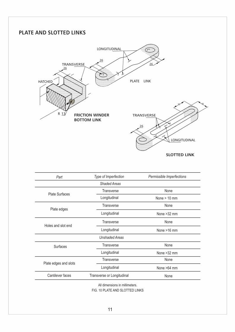
FIG. 10 PLATE AND SLOTTED LINKS
Part Type of Imperfection Permissible Imperfections
Shaded Areas
Plate SurfacesTransverse None
Longitudinal
Plate edgesTransverse None
Longitudinal
Surfaces Transverse None
Longitudinal
Unshaded Areas
None > 10 mm
None >32 mm
None >32 mm
Holes and slot endTransverse None
Longitudinal None >16 mm
Plate edges and slotsTransverse None
Longitudinal None >64 mm
Transverse or Longitudinal NoneCantilever faces
11
26
TRANSVERSE
LONGITUDINAL
WW
SLOTTED LINK
PLATE AND SLOTTED LINKS
TRANSVERSE26
HATCHED
R 13
26
PLATE LINK
FRICTION WINDERBOTTOM LINK
26
LONGITUDINAL

HUMBLE DETACHING HOOK
12
LONGITUDINAL
TRANSVERSE
SIDE PLATE
2626
26
26
LONGITUDINAL TRANSVERSE
26
2626
76
76
CENTRE PLATE
76
76
2626
TRANSVERSE
LONGITUDINAL
26
CENTRE PLATE
LONGITUDINAL
26
2626
76
76
TRANSVERSE
CENTRE PLATE
All dimensions in millimeters.
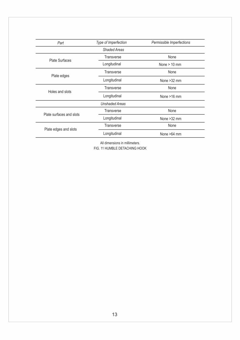
FIG. 11 HUMBLE DETACHING HOOK
Part Type of Imperfection Permissible Imperfections
Shaded Areas
Plate SurfacesTransverse None
Longitudinal
Plate edgesTransverse None
Longitudinal
Plate surfaces and slotsTransverse None
Longitudinal
Unshaded Areas
None > 10 mm
None >32 mm
None >32 mm
Holes and slotsTransverse None
Longitudinal None >16 mm
Plate edges and slotsTransverse None
Longitudinal None >64 mm
13

14
All dimensions in millimeters.
FIG. 12 ROPE CAPPEL
Part Type of Imperfection Permissible Imperfections
Shaded Areas
Bands, safety blockand wedges
Transverse None
Longitudinal
LimbsTransverse None
Longitudinal
WedgesTransverse None
Longitudinal
Unshaded Areas
None > 10 mm
None >16 mm
None >32 mm
LimbsTransverse None
Longitudinal None >64 mm
ROPE - CAPPEL
LONGITUDINAL
BANDS
Mn STEELSAFETY BLOCKS
LONGITUDINAL
TRANSVERSE
LIMBS
26
38
38
Mn STEEL WEDGES
15
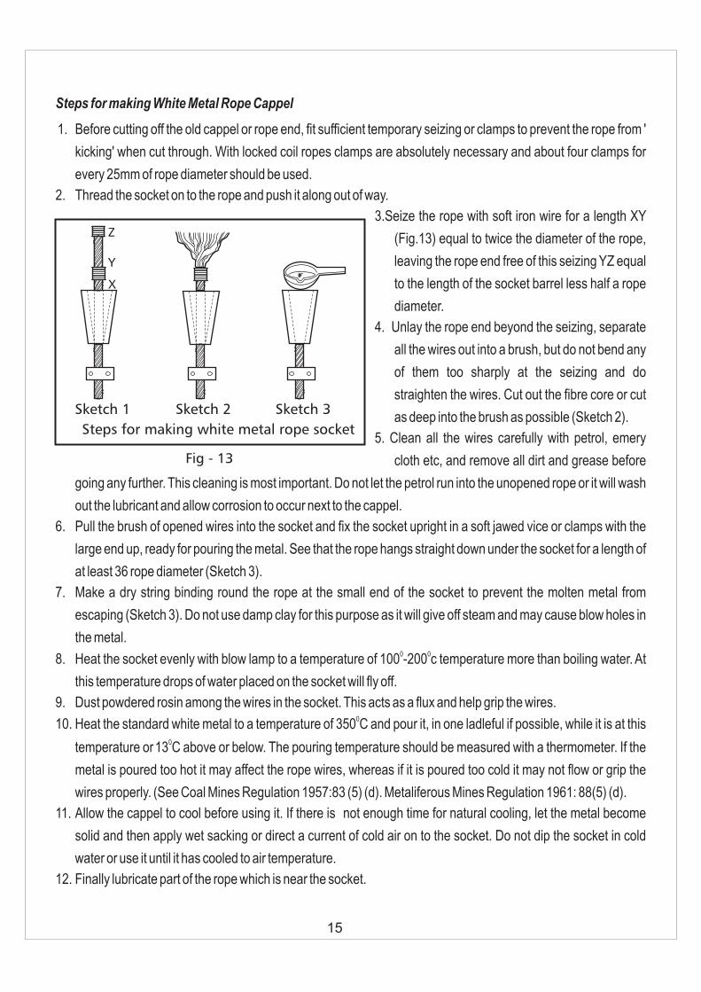
Steps for making White Metal Rope Cappel
1. Before cutting off the old cappel or rope end, fit sufficient temporary seizing or clamps to prevent the rope from '
kicking' when cut through. With locked coil ropes clamps are absolutely necessary and about four clamps for
every 25mm of rope diameter should be used.
2. Thread the socket on to the rope and push it along out of way.
3.Seize the rope with soft iron wire for a length XY
(Fig.13) equal to twice the diameter of the rope,
leaving the rope end free of this seizing YZ equal
to the length of the socket barrel less half a rope
diameter.
4. Unlay the rope end beyond the seizing, separate
all the wires out into a brush, but do not bend any
of them too sharply at the seizing and do
straighten the wires. Cut out the fibre core or cut
as deep into the brush as possible (Sketch 2).
5. Clean all the wires carefully with petrol, emery
cloth etc, and remove all dirt and grease before
going any further. This cleaning is most important. Do not let the petrol run into the unopened rope or it will wash
out the lubricant and allow corrosion to occur next to the cappel.
6. Pull the brush of opened wires into the socket and fix the socket upright in a soft jawed vice or clamps with the
large end up, ready for pouring the metal. See that the rope hangs straight down under the socket for a length of
at least 36 rope diameter (Sketch 3).
7. Make a dry string binding round the rope at the small end of the socket to prevent the molten metal from
escaping (Sketch 3). Do not use damp clay for this purpose as it will give off steam and may cause blow holes in
the metal.0 0
8. Heat the socket evenly with blow lamp to a temperature of 100 -200 c temperature more than boiling water. At
this temperature drops of water placed on the socket will fly off.
9. Dust powdered rosin among the wires in the socket. This acts as a flux and help grip the wires.010. Heat the standard white metal to a temperature of 350 C and pour it, in one ladleful if possible, while it is at this
0temperature or13 C above or below. The pouring temperature should be measured with a thermometer. If the
metal is poured too hot it may affect the rope wires, whereas if it is poured too cold it may not flow or grip the
wires properly. (See Coal Mines Regulation 1957:83 (5) (d). Metaliferous Mines Regulation 1961: 88(5) (d).
11. Allow the cappel to cool before using it. If there is not enough time for natural cooling, let the metal become
solid and then apply wet sacking or direct a current of cold air on to the socket. Do not dip the socket in cold
water or use it until it has cooled to air temperature.
12. Finally lubricate part of the rope which is near the socket.
Fig - 13
Sketch 1 Sketch 2 Sketch 3
X
Y
Z
Steps for making white metal rope socket

16
White Metal Safety Block is fitted as detailed in W.M. Cappel Installation.After
fitting the White Metal Block, the cappel should now be fitted as follows :
Note : Prior to assembly, remove any portective paint, grease or backing strip
from cappel limbs and wedges. Remove any trace of of rust which may have
accumulated on the wedge back and grooves, and also on the inside of the
limbs over the area on which the wedges operate. Emery cloth only should be
used for this purpose. Remove any burrs or damage on wedges and limb
section particularly the area over which the wedges operate which may have
occurred in handling, storage or transit, (if left they may interfere with the
movement of the wedges.)
Thread cappel bands on rope in reverse number order i.e. No. 1 is threaded
onlast. Make sure that the taper of the inner sides of the bands accords with the
outside taper of the cappel limbs. This is shown by an arrow stamped on the
limbs.
Thoroughly clean any grease and lubricant from that portion of the rope which
will be gripped by the wedges and ensure that the rope is straight, clean and dry,
Clean also the Backs of the wedges and the
inner sides of the cappel limbs. Then apply a
light smearing of grease to the Backs (not The
Grooves) of the wedges and the inside of the limbs. The Groove Of The Wedges
Must Be Clean And Dry. Place the wedges around the rope approximately in the
position they will take up when in the cappel.
Fit the cappel limbs over the wedges and draw downwards until the
ends of the limbs are flush with the thin end of the wedges. The rope should then
be drawn through the wedges until the safety block is approximately 20mm from
the bottom of the wedges.
The bands should now be drawn over and tapped down on the cappel limbs. The
band numbered 1 should be fitted adjacent to and encircling the safety block.
Using drifts which should fit snugly on the edges of the bands adjacent to the
cappel limbs (starting with No. 2) should be driven down until they sound tight
and solid. The driving down should be on alternative bands so that all the bands
are driven down progressively. Preferably two strikers should be employed to
facilitate uniform tightening. The sides of each band adjacent to the wedges
should never be struck, as otherwise burrs can be caused which may foul the
wedges and retard their movement.
Band No.1 is intended only as a protection for the safety block and need not be driven on to a very tight fit. It is
not a “working” band and its position on the limbs is not critical. The top (”point”) band at the cappel mouth (No. 4
INSTRUCTION FOR FITTING FRICTION WEDGE CAPPEL
Step 1 for fitting F.W.R.C.
Step 2 & 3 for fitting F.W.R.C.
Fig - 14
Fig - 15

17
in the illustration) being the last and easiest to drive on may receive the hardest
blows.
This Must Be Avoided. It needs to be tight, but not excessively so.
The “Working” bands (Nos. 2, 3 and 4) in the illustration properly driven on,
should be spaced about equally along the cappel limbs, the top (”point”) band
being slightly short of the end of the cappel.
Fig - 16
Notes On Safety Hook :
Inspection : Coal Mines Regulation 1957 No. 81 (2) (a) requires inspection of
all parts of Suspension Gear including safety hook every six months and if
necessary at shorter interval.
Maintenance :
1. Check all nuts and split pins for wear of safety Hook and slackness. Renew
split pins at regular intervals.
2. Check outer plates for wear and cracks around shackle eye positions. Do
not weld up.
3. Check the copper pin for wear and partial shear which may be due to
wear and slackness in platework and pivot pin. Pivot pin must be good fit in
platework.
4. Check all plates for flatness
by means of straight edge.
5. Ensure that hooks are always well lubricated and as clean as
possible. Avoid excessive accumulation of grease and coal
dust. Ensure that the locking bolt slot is free from grease and
other matter which may hinder the action of the bolt in an
overwind.
6. Ensure that the Lifting shackle (for release of hook after
overwind) is maintained in a clean and corrosion-free
condition.Ensure that it is the correct one for the hooks in use
and always ensure that several persons are certain where the
shackle is located.
Precaution :
1. Ensure that the catch plate position is such that sufficient clearance exists to allow complete detachment of the hook before the cappel makes contact with the sheave in an overwind.
2. Ensure that adequate clearance exists between catch plate hole and all attachments including rope cappel so that unrestricted passage through the catch plate is possible.
Humble Safety Hook
Fig - 17
Step 4 for fitting F.W.R.C.

18
1. Check that the jaws of shackles are parallel.
2. Check that the safety chains are slack after installation in
case of six-legged C.S. Gear.
3. Ensure that the length of the slings are 2230mm for four
legged CS gear & 2725mm for corner chains and 2575mm
for safety chains in case of six-legged C.S. Gear.
4. Ensure that there is not much slackness between jaws for
shackle and the cage hangers. DGMS (tech.) circular No.
7 of 1987 has given the following guidelines to the industry
which must be followed.
NOTES ON INSTALLATION OF SHACKLE & SLINGS
Fig - 17
Safe Workingload
Bore dia Dmm
Thickness 't'of hanger
in mm
Width ofhanger W
mmB
k N Tonne
50 5 30 25 100 90
80 8 39 25 150 120
100 10 39 25 150 120
Installation
l Inspections of attachment of bridle chains to cage hangers have revealed that at some of the installations
the fitment between D-shackle pins and cage hangers was not proper causing excessive wear. This
happens mainly due to abnormal clearance between shackle pins and cage hanger hole as well as
improper inclination, width and thickness of cage hangers.
l To deal with the above difficulties, guidelines given above must be followed.
DETAILS OF CAGE HANGER
Attachment for Bridle Chain
W
Dmm0 0a =10 TO 15
B
t
19
Inspection
Coal mine regulation lays down following periodicity for inspection
Coal Mine Regulation 83-
1. Daily Inspection :
Every part of cage suspension gear shall be examined carefully for its proper and safe working.
2. Monthly Inspection :
Every detaching plate of safety hook shall be examined and its opening dimension shall be measured and
recorded once in at least thirty days.
3. Half Yearly Inspection :
For proper maintenance, it is required that all cage chains in general use and other parts of suspension gear
between rope and the cage including the detaching hook, shall be taken apart, cleaned and carefully examined
as to wear and tear by gauging and for rust and cracks once atleast every six months or if necessary at shorter
intervals.
4. It is suggested that where the conditions are severe, the present visual method of detection of cracks and
flaws always does not indicate the correct health of Cage Suspension Gear or its components. In such case
magnetic and ultrasonic tests or any other N.D. Test can be done, to detect any crack or flaw in the suspension
gear or its components which are regular in service.
PROPER STORAGE OF CAGE SUSPENSION GEAR & ITS PARTS.
- C.S. Gears and it's components must be stored in shelves above floor level.
- They must not be exposed to direct sunlight.
- Proper labeling of components identifying the manufacturer must be done.
- If storage is likely to be more than one year then anti-rust lubricant must be used.
- Principal of first-in first-out must be implemented.

20
NORMS OF DISCARD OF CAGE SUSPENSION GEAR COMPONENTS.
-Rope Cappels (Wedge Cappels)
1. Tightening bands being damaged, becoming out of shape due to mishandling or any other reason.
2. Marked pitting/corrosion appearing on the bands and the body.
3. Deformation in the body or excessive were on the outer or inner surface.
4. Whether the last tightening band could be tightened up to 6mm or less measured from the bottom of the tapered wedge.
5. Wear to an extent of 5% to 6% or more on the eye portion of the cappel.
Safety Hook
1. Wear on the centre pin exceeding 10% in top and bottom shackles and pins.
2. Wear exceeding 1% in top and bottom shackles and pins.
3. In the top portion of the safety hook if slackness in the pin in more than 1.6mm.
4.(a) Wear on the outer plate shall to be not more than 0.3 mm.
(b) Pitting/corrosion on the inner/working plates.
5.(a) Obliquity in the hole for the copper pin.
(b) Obliquity of holes in the top and bottom shackles (outer) limited to 10%
6. Where the shackle eye has rubbed on the plates and the wear due to such rubbing exceeds 1.6mm.
7. Any deformation, pitting/corrosion or any other defect on the projected fins of the working plates as well as the protion which rests on the catch plate.
Note : The detaching plate or safety hook is considered as a part of the hook. In case of any notch/groove due to rubbing of rope or otherwise on the circumference of the plate hole, the plate should be rejected. If there is no defect like corrosion, groove in the hole of the plate and obliquity in the holes of the tightening bolts, the plate can be allowed further use after proper heat treatment and tests for cracks etc.
Distribution Plates :
1. Marked pitting and corrosion.
2. Obliquity in the holes exceeding 10% of the original dia.
3. Where the shackle eye has rubbed on the distribution plate and wear due to rubbing exceeds 1.6mm.
Shackles and Pins :
1. Wear on shackle eye sides exceeds 1.6mm.
2. Wear on the shackle eye hole exceeds 10% of the original diameter.
3. Obliquity in the hole exceeds 10% of the original diameter.
4. Wear on pin exceeds 10% of the original diameter.
Suspension Chain Slings :
1. Marked pitting and corrosion.
2. The wear on the contact surface of the links exceeds 10% to 12% of the nominal diameter of the link.
21
POINTS TO PONDER
1. No rusting used to appear on the imported C.S. Gear, Humble safety hook or Reliance Friction Wedge
Rope Cappel even after long storage & exposure to adverse environment.Indigenous C.S. Gear &
Components gets rusted much earlier.
Suggestion : Grit Blasing of components is advocated to prevent earlier rusting.
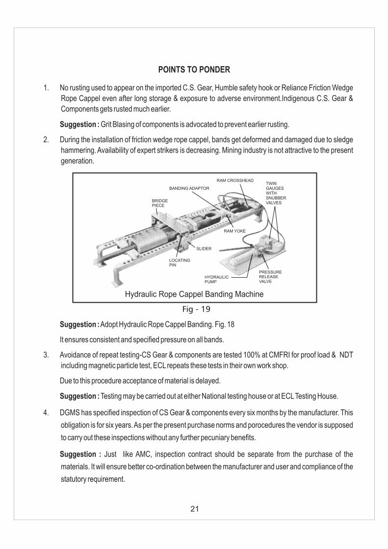
2. During the installation of friction wedge rope cappel, bands get deformed and damaged due to sledge
hammering. Availability of expert strikers is decreasing. Mining industry is not attractive to the present
generation.
Suggestion : Adopt Hydraulic Rope Cappel Banding. Fig. 18
It ensures consistent and specified pressure on all bands.
3. Avoidance of repeat testing-CS Gear & components are tested 100% at CMFRI for proof load & NDT
including magnetic particle test, ECL repeats these tests in their own work shop.
Due to this procedure acceptance of material is delayed.
Suggestion : Testing may be carried out at either National testing house or at ECL Testing House.
4. DGMS has specified inspection of CS Gear & components every six months by the manufacturer. This
obligation is for six years. As per the present purchase norms and porocedures the vendor is supposed
to carry out these inspections without any further pecuniary benefits.
Suggestion : Just like AMC, inspection contract should be separate from the purchase of the
materials. It will ensure better co-ordination between the manufacturer and user and compliance of the
statutory requirement.
Hydraulic Rope Cappel Banding Machine
Fig - 19
BRIDGEPIECE
BANDING ADAPTOR
RAM CROSSHEADTWINGAUGESWITHSNUBBERVALVES
RAM YOKE
SLIDER
LOCATINGPIN
HYDRAULICPUMP
PRESSURERELEASEVALVE

22
5. ISO 9001-2000 - DGMS has advised the manufacturer 3 years earlier to obtain ISO certification, This
may be followed up. It will ensure better products for the industry. In case of any undesirable happening
traceability of the cause & reasons are easier.
6. Re-introduction of five ton safety hook.
In the industry about 80% installation are of 5 ton capacity. In some of these installations industry feels
the desirability & necessity of installing 5 tons safety hook instead of 8 tons. DGMS may permit use of 5
tons. Hook on the merit of case to case basis.
7. Under utilized shaft capacity. — At present total annual coal production in India is about 430 MT, (2007)
of which 10% ie. 43 MT comes from underground coal mines. About 50% of which comes from shaft. At
the time of nationalization from under ground coal mines the poroduction was 60 MT which was 84% of
the total production.
In most of the pits no of winding cycle per day is much less than it’s actual rated capacity and
accordingly utilization of CS Gear & winding rope is much less.
With projected higher production of underground coal utilisation of C. S. Gear equipments is likely to be
better.
23
QUESTION AND ANSWER SESSION
Delegate : Is drilling & welding of Cage-Hanger is permissible.
Sri G. N. Venkatesh. D. M. S. (Mech.) : Ensure there is no slackness between jaws of cage
shackle & hangers. To achieve the above objective and at the same time, if strength of cage
hangars, are not impaired, drilling & welding may be carried out.
Delegate : At what frequency, the copper shear pin is to be changed.
Author :
After i) Every six months during half yearly detailed examination (C.M.R. 83) of Safety Hook.
ii) At shorter interval, if there is any slackness, wear, pitting on pin, or any doubt about the strength
of pin.
Delegate : Why DGMS has introduced 8 tons Safety Hook for 5 tons C. S. Gear installation.
Author : DGMS has introduces 8 tons Safety Hook for 5 tons installation for better Safety. 5 tons
Safety Hook-detaching plate has hole dia of 155mm. Maximum width of 5 tons. F.W.R.C. Band is
150mm leaving a gap of 5mm. Any unusual swinging of rope used to cause detachment of bands
of F.W.R.C. Detaching Plate hole dia for 8 tons Safety Hook is 180mm & there is no chance of
fouling of 5 tons F.W.R.C. Bands against hole of detaching plate.

BIBLIOGRAPHY
1. Becker, W. H. Caps or attachments for winding RopesTrans. Inst. Min. Engineers. Vol. : XXIV, 1905.
2. Biggart, W. Gibson and Mc. Geogh, Peter L. The Design
and Manufacture of Cage Suspension Gear. JournalAssoc. Min. Elec. And Mech. Engrs. Vol, 40 Oct, 1959.
3. H. Dolan, M. I. Mech, E., M.I.E.E., A.M.I.Min.E. Rope
Attachments and associated apparatus for hoisting and
guide Ropes in Vertical Mine Shafts. Paper read at CMRI
Dhanbad Dec' 1961.
4. Coal Mines Regulations - 1957.
5. DGMS Circulars.
6. IS 7587 2006 Part 1 - 7. Cage Suspension Gear for Winding
in Mines - Specification.
24

l J. P. Goenka B.Sc (Min. Engg.) Hons A.I.S.M.F.I.E., M.M.G.I :
Distinguished alumnus of Indian School of Mines of 1961 - Mining batch.
l He has represented MGMI at Dusseldorf Mining Congress and world Mining Congress.
l He has been the Hony. Secy. of M.G.M.I. for many years.
l Convenor of 1st Asian Mining Exhibition in 1991.
l Recepient of John Dunn Medal & Sukumar Rakshit medal from MGMI
l He started his career as first class manager in Turner - Morrison group of collieries & at present the CEO of Nanda Millar Co., engaged in export and manufacture of mining machinery and engineering products.
l Representing 'ROSCH' group of companies, Germany.
l He is an active member of CII mining Construction & Equipment Division since many years.
l A social worker & Keen golfer
BIO - DATA OF AUTHOR

32A, Chittaranjan Avenue, 2nd Floor, Kolkata - 700 012Phone : 2212 3530 / 31, 2212 1783, Mobile : 98300 90461
Fax : 91-33-2212 2070, E-mail : [email protected] Web Site : www.nandagroup.com
NANDA MILLAR CO.
U K A SQUALITY
MANAGEMENT