Embed Size (px)
Citation preview

Cabletron SystemsATM Technology Guide


Notice
Notice
Cabletron Systems reserves the right to make changes in specifications and other information contained in this document without prior notice. The reader should in all cases consult Cabletron Systems to determine whether any such changes have been made.
The hardware, firmware, or software described in this manual is subject to change without notice.
IN NO EVENT SHALL CABLETRON SYSTEMS BE LIABLE FOR ANY INCIDENTAL, INDIRECT, SPECIAL, OR CONSEQUENTIAL DAMAGES WHATSOEVER (INCLUDING BUT NOT LIMITED TO LOST PROFITS) ARISING OUT OF OR RELATED TO THIS MANUAL OR THE INFORMATION CONTAINED IN IT, EVEN IF CABLETRON SYSTEMS HAS BEEN ADVISED OF, KNOWN, OR SHOULD HAVE KNOWN, THE POSSIBILITY OF SUCH DAMAGES.
Copyright 1997 by Cabletron Systems, Inc. All rights reserved.
Printed in the United States of America.
Order Number: 9032059 February 1997
Cabletron Systems, Inc.P.O. Box 5005Rochester, NH 03866-5005
Cabletron Systems is a registered trademark.
All other product names mentioned in this manual may be trademarks or registered trademarks of their respective companies.
i

Notice
ii

Contents
Chapter 1 Introduction
Purpose of This Manual.............................................................................................................. 1-1Document Organization ............................................................................................................. 1-1Document Conventions .............................................................................................................. 1-2
Notifications .......................................................................................................................... 1-2Formats .................................................................................................................................. 1-2
Related Documentation .............................................................................................................. 1-3
Chapter 2 About ATM
Introduction to ATM ................................................................................................................... 2-1Where ATM Started.............................................................................................................. 2-2ATM Workgroups and LAN Backbones ........................................................................... 2-3The Promise of ATM ............................................................................................................ 2-3
Interoperability, the Ideal of Networking ................................................................................ 2-4Standards and Compliance ................................................................................................. 2-5The OSI Model, Basis of Standards.................................................................................... 2-5Application of the OSI Model............................................................................................. 2-9
ATM Model................................................................................................................................. 2-10ATM Adaptation Layer...................................................................................................... 2-11Quality of Service Issues.................................................................................................... 2-12ATM Adaptation Layer Service Classification ............................................................... 2-12ATM Layer........................................................................................................................... 2-14Physical Layer ..................................................................................................................... 2-14
ATM Standard Making Bodies ................................................................................................ 2-14Cabletron Supported Specifications........................................................................................ 2-15
iii

Contents
Chapter 3 Basic ATM
Switching Channels .....................................................................................................................3-1Connectionless Networks....................................................................................................3-1Connection-Oriented Networks .........................................................................................3-3
Cell Switching...............................................................................................................................3-4Frame-Based Networking ...................................................................................................3-4Cell-Based Networking........................................................................................................3-5ATM Cell Organization........................................................................................................3-6
Cell Preparation ...........................................................................................................................3-6AAL1 ......................................................................................................................................3-7AAL3/4 Cell Preparation ....................................................................................................3-9AAL5 Cell Preparation....................................................................................................... 3-11
Connections ................................................................................................................................3-13Physical Connections .........................................................................................................3-13Virtual Connections............................................................................................................3-13Virtual Channel Types........................................................................................................3-16
Cell Handling .............................................................................................................................3-17Multiplexing ........................................................................................................................3-17Interleaving..........................................................................................................................3-21
Chapter 4 Cells
Cell Format ...................................................................................................................................4-1Types of ATM Cells...............................................................................................................4-2Cell Formats...........................................................................................................................4-2Header Components ............................................................................................................4-4
Chapter 5 Call Management
Address Assignment ...................................................................................................................5-1Call Establishment .......................................................................................................................5-2
Connection Request..............................................................................................................5-2Traffic Contracts ....................................................................................................................5-3Route Resolution...................................................................................................................5-4Connection Establishment...................................................................................................5-6Acceptance.............................................................................................................................5-7
Switch Operations........................................................................................................................5-8Call Tear Down........................................................................................................................... 5-11
iv

Contents
Chapter 6 Traffic Management
Quality of Service Parameters.................................................................................................... 6-1Traffic Parameters ........................................................................................................................ 6-3Classes of Service......................................................................................................................... 6-4Traffic Management..................................................................................................................... 6-6
Traffic Shaping ...................................................................................................................... 6-7Traffic Policing ...................................................................................................................... 6-7
Chapter 7 ATM in the LAN
Adapting ATM to Connectionless LANs ................................................................................. 7-1ATM Connection Types ....................................................................................................... 7-2The Rationale for LAN Emulation ..................................................................................... 7-3
LAN Emulation Function and Deployment ............................................................................ 7-3LANE Connectivity.............................................................................................................. 7-4
LAN Emulation Operation......................................................................................................... 7-5Initialization .......................................................................................................................... 7-5Data Transfer ......................................................................................................................... 7-7LAN Emulation and the Spanning Tree Protocol .......................................................... 7-11
Control and Data Connections ................................................................................................ 7-12Control Connections .......................................................................................................... 7-12Data Connections ............................................................................................................... 7-13
Appendix A ATM Media
ATM Media Specifications.........................................................................................................A-1
Index
v

Contents
vi

Chapter 1
Introduction
Purpose of This ManualWelcome to the Cabletron Systems ATM Technology Guide. This guide is intended to provide the information necessary to allow Network Managers to increase their understanding of Asynchronous Transfer Mode (ATM) technology, its operation, and the Cabletron Systems approach to ATM.
Document OrganizationThis guide provides a basic overview of what ATM technology is and how it works. The overview presented in Chapter 2 and 3 gives a basic foundation for more detailed material presented in the following chapters. Subsequent sections give a more detailed understanding of ATM, the operation of the technology and its function in Local Area Networks (LANs) and Wide Area Networks (WANs).
The following summarizes the organization of this document:
Chapter 1, Introduction, covers the use and contents of this guide.
Chapter 2, About ATM, discusses the evolution and promise of ATM as a multiple media networking technology, and gives simple explanations for what ATM is and what it does.
Chapter 3, Basic ATM, illustrates the basic operation of ATM, and introduces the main concepts to be covered in greater detail in subsequent chapters.
Chapter 4, Cells, deals with ATM cell formats, organization, and components.
Chapter 5, Call Management, provides detailed information about how an ATM connection is set up, how data flows across the connection, and the way in which it is torn down when a station decides to disconnect.
1-1

Introduction
Chapter 6, Traffic Management, describes the metrics and operations used by ATM networking devices to control the flow of cells over the network and ensure effective use of the network.
Chapter 7, ATM in the LAN, shows how ATM is implemented into Legacy LANs using the LAN Emulation Protocol, and discusses what the LAN Emulation protocol procedure does and how it functions.
Appendix A, ATM Media, lists and describes the various cabling types that may be used with ATM networks and the requirements and specifications that cabling must meet.
Document Conventions
Notifications
Formats
References to chapters or sections in this document are printed in boldface type.
References to other publications or documents are printed in italic type.
NOTENote symbol. Calls the reader’s attention to any item of information that may be of special importance.
1-2 Document Conventions

Introduction
Related DocumentationThe following publications may be of assistance to you in the network design process. Several of these documents present information supplied in this ATM Technology Guide in greater or lesser detail than they are presented here.
• Cabletron Systems Cabling Guide
• Cabletron Systems Ethernet Technology Guide
• Cabletron Systems Glossary of Terms
• Cabletron Systems Token Ring Technology Guide
• Cabletron Systems FDDI Technology Guide
For additional product or other information visit us at http://www.cabletron.com or contact Cabletron Systems for customer or sales support by phone (603) 332-9400.
Related Documentation 1-3

Introduction
1-4 Related Documentation

Chapter 2
About ATM
This chapter discusses the evolution and promise of ATM as a multiple media networking technology, and gives simple explanations for what ATM is and what it does.
Introduction to ATMThere are two basic types of communication networks: public networks and private networks. Public networks are owned and operated by telephone companies and television cable companies, and provide worldwide access to voice, data, and video communication services. They are considered to be public because this network can be accessed from anywhere in the world when a user decides to pick up a telephone, turn on a television, or gain access to the internet through a computer and modem.
Private networks such as Local Area Networks (LANs) are owned, operated and controlled by corporations, companies, government agencies and universities. These LANs were once geographically isolated to individual companies or sites. Today these same networks use public networks as intermediate connections to other private networks. LANs are mainly data communications networks, but are recently beginning to transmit more and more broadband communications like voice and video.
Both public and private networks process large amounts of information. These networks provide reliable service and good response time. However, as bandwidth demands for greater speed, efficiency, and reliability, an emerging technology called Asynchronous Transfer Mode (ATM), has matured to fulfill the networking requirements of modern public and private computer networks.
2-1

About ATM
Where ATM Started
Telecommunications carriers were the first to develop ATM. The goal of their project was to define and standardize a transmission over any synchronous channel that would unite media services and deliver them in a fast, inexpensive, reliable and efficient manner. Once the ATM technology met these goals, it became the vehicle for a Broadband-Integrated Services Digital Network (B-ISDN), which is a digital transmission standard defining communication protocols permitting telephone networks to carry data streams over Wide Area Networks (WANs).
Carriers understand the need for a medium to carry broadband communications over a high-capacity network, because they are interested in reducing the cost and number of different networks that they must maintain for a variety of users. These different networks are becoming expensive to operate and support as the demand for bandwidth rises. For this reason, ATM has become an attractive networking technology for both WAN carriers and LAN environments. It provides high bandwidth and does not use network capacity unless there is information to be sent. When there is information to be sent, it is packaged into cells that travel along an assigned channel. When a particular device is not transmitting, the spare capacity can be used by other devices. When no devices are transmitting, the channel is filled with idle cells.
By allocating only the bandwidth needed by a user’s applications, ATM could lead to greater network efficiency and productivity in LAN environments with significant cost savings. In the future, Native ATM technology (ATM networks without connected legacy networks) has the potential to make both LANs and WANs more transparent by offering a homogenous connection between any two points on the globe. This connection would be direct, without having to be routed or bridged over different technologies before finally making a link.
One of the important questions facing network designers examining ATM technology is “how will it fit into my existing network”? Due to the relative expense and the pre-standardized nature of the ATM technology, ATM is being gradually implemented into today’s LANs, most often as a backbone technology.
2-2 Introduction to ATM

About ATM
ATM Workgroups and LAN Backbones
ATM backbones currently used in LANs create high-speed communication links between users in different workgroups or between different users located in different areas. Backbones are the central transmission media of larger networks carrying large amounts of data at high speeds.
ATM is becoming more widely accepted as a LAN backbone technology, but its transition has not been smooth due to the complexity of the technology needed to mesh ATM backbones with existing Ethernet, Token Ring, and FDDI LANs. The slow adoption of LAN Emulation, and the status of specifications for Classical IP have complicated the migration to ATM backbones for some users. However, ATM’s speed and ability to multiplex different communication media types makes it an attractive networking solution.
ATM backbones provide high transmission speeds and bandwidth in a way that supports user mobility, easily modified workgroup connectivity, and the base of existing network-oriented applications in LANs. As a LAN backbone, ATM is used to connect centralized workgroup hubs supporting hundreds of connections. ATM provides large amounts of bandwidth and is implemented as high-speed switching matrixes within the backplane of ATM switches and next generation smart hubs. Within the backplane, ATM will provide the high-speed interconnection between modules and networks in the same manner as used in the physical backbone, essentially bringing the ATM backbone network into the switch or smart hub. ATM used as a WAN backbone solution can have the capacity to carry transmissions between major cities, states, or countries. ATM WANs are currently being implemented by some telecommunications carriers. It is quite likely that this event will spark even more implementations in LAN backbones in the near future.
The Promise of ATM
If the computer industry had the ability to turn back time and start with a clean slate concerning computer networking, it might well have gone with Native ATM. Most of the ATM concepts and features discussed in this guide would be optimized in any type of data applications. ATM has been an evolving technology that has taken years (1991-1997) of network development, investment and implementation to migrate and complement sizable, established, legacy-network environments.
Although ATM has shown much promise in its goals for wide-spread implementation in both LANs and WANs as a far reaching and revolutionary network solution, it has gone through some growing pains. The acceptance and implementation of ATM has been gradual because of its cost, development, and investment in existing networking technologies. Network designers are beginning to utilize ATM backbone switches for their existing networks where it has made the most practical and cost-effective sense. The type and volume of traffic may also affect decisions to use ATM as a networking solution. ATM may be a more practical networking approach for users that have high multimedia traffic or exceedingly high-bandwidth demands.
Introduction to ATM 2-3

About ATM
The hope of implementing Native ATM in all networks over time rests in encouraging the technology to migrate and coexist with legacy LANs and WANs until it gradually positions itself to live up to its potential as a unifying technology. Native ATM to the desktop will win wide-spread acceptance when applications drive users to find a faster, more capable transport service. ATM to the desktop will become more widespread when an ATM infrastructure that supports it becomes more fully developed in both LANs and WANs.
In WANs, carriers have the resources to create a major ATM infrastructure, and are motivated to do this because ATM “flattens the network,” decreasing the number of multiple separate networks they need to support. Carriers are now investing in equipment to upgrade their infrastructure and are buying ATM WAN and LAN switches along with other access devices to build ATM networks that pave the way for a single, high-speed, and universal networking architecture that is compatible with current and planned electrical and optical cables.
Interoperability, the Ideal of NetworkingIdeally, all devices placed on any network should be able to transfer information in a usable fashion and understandable format to any other station. For some time, however, this was not always the case. Different companies, even within the same industry, have different ways of designing, developing, and constructing their products. Different views of how a network should operate led to radically different products and methods of networking. These early networking implementations were specific to one particular vendor, and would often only work in homogenous environments, where all components used in the network were produced by that single vendor. This method of networking locked customers in to relying on a single vendor for all their networking needs, current and future, which could lead to problems if the network implementation was unsatisfactory. Replacing all present networking equipment with the proprietary solution of another vendor is an extremely costly proposition.
To combat this, the idea of interoperability grew in popularity. Ideally, interoperability means that the networking devices of Vendor X can communicate, problem-free, with the networking devices of Vendor Y.
2-4 Interoperability, the Ideal of Networking

About ATM
Standards and Compliance
Interoperability requires the following of standards: distinct rules and finite margins within which network operation and performance must be kept. If a network does not meet the minimums, or exceeds the maximums of the networking standard that the industry uses, it is said to be “out of specifications,” and may not operate at an acceptable level.
Standards are defined by committee through the operation of standards institutes. Standards institutes are made up of personnel from several firms in the industry who volunteer their time and effort. These volunteers work to compose and ratify an acceptable standard that must be met by any product that refers to itself as “standards-compliant.” Products that are not standards-compliant may cause or experience interoperability problems when operating in a standards-based network. Of course, even in a fully standards-based network, there may still be problems. Most vendors in the industry realize the importance of providing a flexible and open network to all customers, and they seek to eliminate any interoperability problems they notice.
The OSI Model, Basis of Standards
The International Organization for Standardization (ISO) Open Systems Interconnect (OSI) Model provides a framework for the development of system connection standards by defining a consistent hierarchy of rules. The OSI model defines where the needed tasks of system interconnection are performed but not how they are performed. How tasks are performed on a given layer is determined by the protocols, or rules, written for that particular network based on the OSI model. The layers may be implemented in hardware, software, or both. Each layer in a network based on the OSI model performs specific types of functions required for proper system interconnection.
There are seven layers in the OSI Model (see Figure 2-1). They begin with the Physical Layer and end with the Application Layer. Each layer provides services to the layer above it. As the seventh layer is the ‘topmost’ layer, it serves the user directly, and is considered the top of the OSI model.
Interoperability, the Ideal of Networking 2-5

About ATM
Figure 2-1 OSI Model
Layer Seven: Application
The Application Layer is the user’s interface with the network. This layer directly interacts with user application programs to provide access to the network. All other layers exist to support the requirements of the Application layer. The Application layer is usually involved with network-oriented end-user tasks such as electronic mail, network file transfers, and collaborative document preparation.
Layer Six: Presentation
The Presentation Layer deals with data translation and code conversion between devices with different data formats (i.e., ASCII to EBCDIC). This layer also handles translation between differing device types and file formats, as well as data encryption and decryption services. In the transmit mode, the presentation layer passes information from the application layer to the Session layer after it has appropriately modified or converted the data. In the receive mode, the Presentation layer works in reverse passing information from the Session layer to the Application layer.
Layer Five: Session
The Session layer manages the communications dialogue between two communicating devices. The Session layer establishes rules for initiating and terminating communications between devices and can provide error recovery.
Application
Presentation
Session
Transport
Network
Data Link
Physical
7.
6.
5.
4.
3.
2.
1.
2059-01
2-6 Interoperability, the Ideal of Networking
About ATM
Layer Four: Transport
The Transport layer deals with the optimization of data transfer from source to destination by managing network data flow and implementing the quality of service requested by the Session layer. The Transport layer determines the packet size requirements for transmission based on the amount of data to be sent and the maximum packet size allowed by the network architecture. If the data to be sent is larger than the maximum packet size allowed on the network, the Transport layer is responsible for dividing the data into acceptable sizes and sequences each packet for transmission.
When receiving data from the Network layer, the Transport layer ensures that the data is received in order and checks for duplicate and lost packets. If data is received out of order, the Transport layer correctly orders the data and passes the data up to the Session layer for additional processing.
Layer Three: Network
The Network layer accepts data from the Transport layer and adds the appropriate information to the packet to provide proper network routing and some level of error control. Data is formatted by this layer for the appropriate communications protocol, such as IP, IPX, or X.25.
Layer Two: Data Link
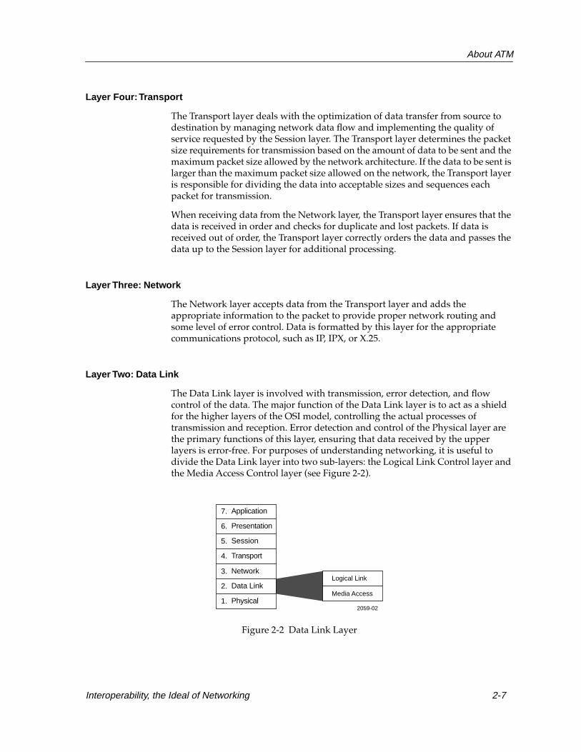
The Data Link layer is involved with transmission, error detection, and flow control of the data. The major function of the Data Link layer is to act as a shield for the higher layers of the OSI model, controlling the actual processes of transmission and reception. Error detection and control of the Physical layer are the primary functions of this layer, ensuring that data received by the upper layers is error-free. For purposes of understanding networking, it is useful to divide the Data Link layer into two sub-layers: the Logical Link Control layer and the Media Access Control layer (see Figure 2-2).
Figure 2-2 Data Link Layer
Logical Link
Media Access
Application
Presentation
Session
Transport
Network
Data Link
Physical
7.
6.
5.
4.
3.
2.
1.2059-02
Interoperability, the Ideal of Networking 2-7

About ATM
Logical Link Control
The Logical Link Control Sublayer shields the upper layers from any particular access method or media. The upper layers are not concerned about whether they are connected to a Token Ring or Ethernet network because the Logical Link Control Sublayer handles the interface. The Logical Link Control provides for a common interface of the layers above to any physical network implementation.
Media Access Control
The Media Access Control, or MAC, Sublayer is responsible for several areas of operation. On the transmit side, the MAC Layer receives data from the Logical Link Control Sublayer and encapsulates it into a packet ready for transmission. The MAC Sublayer determines if the communications channel is available for handling retransmission in the event of a collision on some networks.
Layer One: Physical
At this layer, the transmission media is defined. That definition includes cables and connectors, connector pinouts, voltage levels that represent digital logic levels, bit timing, and the actual network device interface.
2-8 Interoperability, the Ideal of Networking

About ATM
Application of the OSI Model
A user’s perception of network operation appears as direct peer-to-peer communications. The user message appears to go from the sending application directly to the receiving application. In actuality, the user message is routed from the sending application down through the other OSI Model layers of the system (see Figure 2-3). Each layer adds to or modifies the message according to the network operating system’s protocol for each layer. The message passes through all the layers of the system before appearing on the data channel at the Physical layer, where transmission and reception of signals takes place.
Figure 2-3 Transmission through OSI Model
From the data channel the message passes upward through the same layers at the destination device. As the message proceeds from layer to layer, each layer strips off information that was added by its counterpart in the transmitting station. The result is the message as it was originally sent, arriving at the destination station’s Application Layer.
Perceived Path
Actual Path
Application
Session
Transport
Network
Data Link
Physical
7.
6.
5.
4.
3.
2.
1.
Presentation
2059-03
Session
Transport
Network
Data Link
Physical
Presentation
Application7.
6.
5.
4.
3.
2.
1.
Interoperability, the Ideal of Networking 2-9

About ATM
ATM Model The ATM model provides a framework for the development of system connection standards similar to the OSI model. The ATM model borrows the upper four layers of the OSI model without change, however, from the Network Layer down, the ATM model uses a completely different framework for the way connection standards are developed and implemented. It is important to keep in mind that the ATM Adaptation Layer (AAL), ATM Layer, and the Physical Layer provide a new framework designed to accommodate ATM technology similar to the way the Network, Data Link, and Physical Layers are used as a framework to accommodate standards for Ethernet, Token Ring, and FDDI networking technologies. It is also important to understand that the ATM Adaptation Layer, for example, does not necessarily replace or dismiss Network Layer functions. Figure 2-4, shows how the OSI and ATM models relatively compare to one another considering the basic framework for each model.
Figure 2-4 ATM and OSI Models
(This column is not actually a part of either model.)
Application
Presentation
Session
Transport
AAL
ATM
Physical
7.
6.
5.
4.
3.
2.
1.
2059-04
Application
Presentation
Session
Transport
Network
Data Link
Physical
7.
6.
5.
4.
3.
2.
1.
ATM Model OSI Model
NetworkAAL
AAL, ATMData Link
Physical
2-10 ATM Model

About ATM
ATM Adaptation Layer
The ATM Adaptation Layer (AAL) translates and provides a path between the ATM Layer and higher layers. As information passes down the ATM model, the AAL converts and breaks up user information (Protocol Data Units) into 53-byte cells. The reverse process occurs when the AAL converts and reassembles cells into Protocol Data Units as user information passes up the ATM model layers.
The ATM Adaptation layer is designed to reduce the amount of overhead functions for which a network would otherwise be responsible. The purpose of the AAL is to allow most of the overhead functions, like the segmentation and reassembly process, to occur on the end system of a Virtual Channel Connection (VCC), like a Native ATM workstation, and not on the ATM switches themselves. The AAL contains the Convergence Sublayer (CS) and the Segmentation and Reassembly (SAR) sublayer. Figure 2-5 shows a more detailed view of the lower ATM model layers and their sublayers.
Figure 2-5 ATM Adaptation Layer, ATM Layer, and Physical Layer
The Convergence Sublayer prepares the higher layer data for conversion to cells. User information is then divided into segments suitable for packaging in a series of cells for transmission between the endpoints of the communications process by the Segmentation and Reassembly Sublayer. This sublayer segments the received data from the CS into 44, 47, or 48 byte cell data fields depending on the type of ATM adaptation layer service classification they are being prepared for.
NOTEDepending on the adaptation process, not all 48 bytes of the data field are required to be user information and up to four bytes can be used by the adaptation process itself.
Convergence Sublayer
Segmentation and Reassembly
ATMAdaptation Layer
Cell FormatATM Layer
PhysicalLayerTransmission Convergence
Physical Medium2059_05
Transport Layer
ATM Model 2-11

About ATM
For the incoming cell, the Segmentation and Reassembly Sublayer and Convergence Sublayer rebuild the cells into data that can be processed by the higher layers, such as the Transport, Session, Presentation, and Application Layers. How and which ATM Adaptation Layer process is used and completed depends on the type of traffic being transmitted. The AAL is what liberates the network from concerning itself with different traffic types, and it is the ATM Layer’s responsibility to route cells from one point to another based on the information contained in the header. The AAL also provides extra services including recovery of clocking information, error correction, retransmission and support for specialized ATM.
Quality of Service Issues
When an ATM station connects to the ATM network, it arranges a contract with the network based on Quality of Service (QoS) specifications. This contract specifies an envelope that describes the user’s traffic flow parameters specified by the ATM Forum User-to-Network Interface (UNI) 3.0, 3.1, and 4.0 specifications. These specifications include the traffic type, cell loss ratio, sustained and peak bandwidth, burst length, and Quality of Service class. The Quality of Service parameter also requires timing Cell Transfer Delay (CTD) and Cell Delay Variation (CDV). Both parties negotiate and agree on a Quality of Service contract when it is determined what the ATM network can provide, and what the transmission requirements are of the user.
ATM Adaptation Layer Service Classification
The ATM model currently has three different classes of Adaptation Layers in use. Each of the ATM Adaptation Layer classifications is based on the service requirements of the information being transferred or received from either higher or lower layers of the ATM model. Table 2-1 shows the three different classes of information categorized under the Broadband-Integrated Services Digital Network (B-ISDN) standard for the ATM Adaptation Layer. B-ISDN is the digital standard defining communication protocols allowing telephone networks to carry data, voice, and video over Wide Area Networks (WANs).
2-12 ATM Model

About ATM
Each class of the ATM Adaptation Layer is identified by two factors: the type of bit rate and the connection mode, which can provide a constant or variable bit rate service, and a connection or connectionless-orientated mode of operation. Table 2-1 shows the characteristics and services supported by each ATM Adaptation Layer.
A constant bit rate is intended for services requiring guaranteed synchronous timing or clocking between source and destination endpoints, and are usually voice and video transmissions. A variable bit rate is intended to let the bit rate change as the service requirement changes. This service is ideal for data because of its bursty nature and tolerance of delay. In other words, the timing requirement between two endpoints on a network does not have to remain constant.
A connection-oriented mode, like ATM, uses a deterministic access method similar to a telephone call in a public network where the call is set up and the connection is established before information is transferred. During the call setup procedure, special cells hold addressing information in their data fields that is accessed by the network to create a connection. However, when data is being transmitted over an established connection, only the 5-byte cell header needs to be referenced by an ATM switch, to direct information across the Virtual Channel Connection instead of the cell’s 48-byte data field.
Table 2-1. ATM Adaptation Layers
Characteristics AAL1 AAL3/4 AAL5
Timing relationship between source and destination
required not required
Bit rate constant variable
Connection mode connection oriented connection oriented connectionless
Traffic types voice, video and channel emulation data
Class Class A (voice) Class B (video) Class C and D (data)
NOTEATM Adaptation Layer 2 is no longer being used. AAL2 was designed to support variable bit rate service for synchronous, time-sensitive compressed video traffic. This function is currently accomplished by ATM Adaptation Layer 3/4.
ATM Model 2-13
About ATM
Most legacy LANs, such as Token Ring, Ethernet, and FDDI, have a connectionless mode of operation that uses a shared-medium access method among all attached devices. A protocol procedure organizes the sharing process and allows all network devices to use the medium.
When data is shared between connection-oriented and connectionless networks, a procedure must be accepted and used, before they can work with each other. The connectionless-mode is supported by AAL3/4 and AAL5, and works together with the LAN Emulation protocol to set up an ATM connection. For more information on the LAN Emulation protocol, refer to Chapter 7, ATM in the LAN.
ATM Layer
The ATM Layer is responsible for all cell header processing. This layer makes all indentifications of ATM connections, and provides all cell multiplexing and demultiplexing services. The ATM Layer is also where cell construction and processing occurs.
Physical Layer
The Physical Layer defines the physical interface on which the ATM Layer will be running. It takes care of all error control sequences, and places idle cells in the transmitting time slots while stripping them from received time slots. The Physical Layer is concerned with bit transmissions and coding schemes, and generates or recovers time slots. The ATM Physical Layer is designed to work with any existing physical media specification.
ATM Standard Making BodiesCurrently, there is not one accepted standard for ATM, but there are specifications being established for it. The International Telecommunications Union- Telecommunications (ITU-T) is a standards making body that sponsors the American National Standards Institute (ANSI). ANSI is a smaller standards body working within ITU-T that develops world-wide telecommunication and data communication documents and specifications. It is responsible for making a standard for ATM. The Internet Engineering Task Force (IETF), another standards making body, is responsible for creating various addressing protocols for ATM.
2-14 ATM Standard Making Bodies

About ATM
Specifications working toward the implementation of a standard have been maintained and put forward by a group called the ATM Forum. The ATM Forum’s goal has also been to accelerate the deployment of ATM products and services through interoperability specification. It was formed in October 1991 as an impromptu organization of carriers, network equipment providers, semiconductor vendors, government agencies, research groups and customers focused on creating specifications for a single standard. The group has now grown to 900 members making a combined effort to cooperate and agree on specifications before standards are finally set by the ITU-T, ANSI, and the IETF. The ITU-T standard body recognizes the ATM Forum as a credible group working towards this goal. The rationale among different groups for building consensus through the ATM Forum is to ensure that once ATM technology has a set standard, their products and technology adhere to them without becoming proprietary or obsolete. Once a set standard is in place, how well ATM networks operate depends largely on the architecture and design chosen by the various vendors for their ATM products.
The ATM Forum has drafted the User to Network Interface (UNI) specification that became the foundation upon which several other baseline specifications were built. Many of the key baseline specifications are complete and consist of the following: LAN Emulation (LANE), channel emulation, audio/visual multimedia service, Native ATM services, testing specifications, and support of frame relay, Switched Multi-megabit Data Services (SMDS) and Internet Protocol (IP) over ATM.
Cabletron Supported SpecificationsCabletron Systems products currently support some or all of the following ATM specifications:
• LAN Emulation (LANE v1.0)
• User-to-Network Interface (UNI v3.0/3.1/4.0)
- Switched Virtual Channel Signaling (Q.2931)
- Interim Local Management Interface (ILMI)
- Address Registration
- Physical Layer Specifications
• RFC 1483 – IETF Multi-Protocol Encapsulation over AAL5
• RFC 1577 – Classical IP
• RFC 1695 –AToM MIB
In addition, a number of widely used proprietary implementations are supported by Cabletron Systems in order to ensure the maximum interoperability in heterogeneous networks.
Cabletron Supported Specifications 2-15

About ATM
2-16 Cabletron Supported Specifications

Chapter 3
Basic ATM
This chapter discusses the basic operation of an ATM network, and introduces the main concepts that are covered in greater detail in subsequent chapters.
Asynchronous Transfer Mode is fundamentally different from the majority of LAN networking technologies, and may be difficult to visualize. It is important to understand the differences between so-called “legacy LAN” technologies and the operation of ATM networks.
Switching ChannelsUnlike most existing LAN technologies, ATM uses a connection-oriented transmission strategy. Understanding this distinction is easier if the general operation of connectionless networks is first understood. This section examines the operation of connectionless networks and compares them to the connection-oriented operation of ATM.
Connectionless Networks
The connectionless network is based on the concept of the shared segment as a LAN unto itself. Connectionless networks are built around the assumption that every station on the segment must see each and every transmission. Whether the stations all receive a transmission at the same time, as in Ethernet shared segments, or sequentially, as in Token Ring and FDDI networks, is unimportant. The key issue is that traffic from any station on the LAN segment propagates to all other stations on that segment. When a station on the segment receives a transmission, that station determines if it is the station intended to receive that transmission, then the transmission is either processed or discarded accordingly.
3-1

Basic ATM
Segmentation devices, such as bridges, switches, and routers, are used in connectionless networks to isolate segments from one another. In this way, the traffic flow of transmissions is controlled, and inter-segment traffic is minimized.
Since a source station assumes that all stations on the connectionless network receive its transmission, a source station simply packages data into a network frame and transmits. The source station does not know if the destination station is allowed to receive the data frame, and does not even know if the destination station is present on the network.
After finishing the transmission, the source station simply stops. It assumes that the transmission has been received. If there is a problem with the transmission, or if the destination station is unreachable or unable to process the data frame, the source station has no way of knowing this and has no provision for retransmission. It is the task of higher-layer operations, such as Transport Layer (layer 4) and some Network Layer (layer 3) protocols to recognize and deal with problems with transmissions.
Once a frame is transmitted, it is effectively on its own. Because of this, each network frame must contain all of the control information necessary for it to be passed along the network, received by all stations, examined to determine the intended destination station(s), and processed or discarded by those receiving stations. This translates to a large amount of control information that is part of each frame and that must be examined each time a frame is received. Network frames for the Ethernet technology, for example, contain 18 bytes of this control information, that must be read by all receiving stations to determine if that station is the destination or not.
Because each data frame is transmitted without consideration to the state of the network and without an existing well-defined path of transmission, each data frame is treated as a new transmission that must make its way through the entire network. If a source station has 500 data frames to send to a single destination station, the first frame to last frame are treated no differently by the network, and each must be handled by all devices between the two stations. For example, a switch between the two stations, would respond to frame #230 in this transaction just as if it was the first frame of a new data transmission.
3-2 Switching Channels

Basic ATM
Connection-Oriented Networks
A connection-oriented networking technology such as ATM operates quite differently. The connection-oriented network is based on the idea of dedicated links existing between network devices. Much like the circuit-switching technologies used in telephone networks, connection-oriented networks establish a channel, or connection, between two or more stations and restrict the transmission and reception to those established channels.
In a connection-oriented networking technology like ATM, the transmission and reception of data of any kind is dependent upon the network establishing a connection, or “call,” between the end devices involved in the data exchange. A destination station can only receive data from a single source station if it meets the criteria of the transmitting source station. Therefore, a station on a connection-oriented network never sends actual data to a station that is unavailable. If the station to which the source station wishes to send data is unable to receive, the source station is informed that a connection could not be made and no data is transmitted.
As the connection-oriented network is built around the assumption of switched links between devices, the switches in the network are used to create and maintain dedicated connections and relay data across these connections. The switches do not simply block transmissions from certain interfaces.
When a source station wishes to transmit data in a connection-oriented network, it must first request that a connection be established. Much like dialing a telephone number creates a connection between two telephones, this connection request sets up a call between the source station and its destination stations. The process of data transmission can only begin when the source station is notified that the destination stations are connected and ready to receive data.
When this dedicated connection is initiated, the source station can demand that the network provide certain characteristics to the call. These characteristics take the form of guaranteed bandwidth and the various Quality of Service (QoS) parameters. If a source station requires a constant 18 Mbps between it and its destination station, and also requires that the link meet its dependability and delay criteria, the network provides that link and guarantees the speed, dependability and delay characteristics. If the network cannot guarantee those characteristics, it does not allow the call to be set up.
Since the transmission of data is dependent upon the creation of these end-to-end calls, a data transmission in connection-oriented networks does not need the same quantities and types of control information that frames in connectionless networks do. While a connection-oriented network may require a large, specially-organized type of data transmission to establish a connection, once that connection is in place the control information that must be added to each data transmission is minimal. ATM data cells, for example, only require 5 bytes of network control information, much less than the 18 bytes required by each Ethernet data frame.
Switching Channels 3-3

Basic ATM
Once the connection-oriented network establishes a connection, the transmission of data can be continuous and uninterrupted. This use of the dedicated channel can greatly reduce the time required to complete a data exchange between stations. Without the overhead of processing the larger network control information and without the delay of passing data through all the devices in the network as a new transmission, connection-oriented networks make data exchanges simpler and typically faster.
Cell SwitchingATM uses small, fixed-length arrangements of data called cells to transmit data and network control information. The format of these cells provides special operational characteristics to ATM networks. In some cases, the use of cells offers advantages over traditional, frame-based networking technologies, but in others, the use of cells is a limitation. Again, a good way to understand the operation and characteristics of a cell-based network is to compare it to the frame-based networking technologies that are used in many legacy LANs.
Frame-Based Networking
A frame-based network uses random-length frames that are generated by the source system and must fall between a specific set of high and low range values. The actual frames that are generated depend on the amount of data transmitted. An Ethernet frame, for example, has a lower limit of 64 bytes and an upper limit of 1,518 bytes. In some Token Ring network implementations, the size of a frame can even reach up to 18,000 bytes. These variable-sized frames are very efficient at moving large amounts of data, because only a few frames are needed to contain large data transmissions. This efficiency makes frame-based networking popular and highly useful in pure data networks, especially those using media that cannot support high throughput.
Although variable-size frames are efficient, they are very difficult to predict. The amount of delay that a frame experiences between its transmission by the source station and its reception by a destination station is dependent upon several factors related to the size of the frame. Every networking device that the frame passes through has to read and re-transmit the frame. Some networking devices, such as switches and bridges, must read and examine a portion of the frame to determine how to respond to it. Other more complex devices like routers actually translate the frame and examine the data contained in it.
3-4 Cell Switching

Basic ATM
This delay accumulated while moving through a forwarding device, such as a switch or router, is called latency. High latency is usually not a problem for most data applications, but the processing of voice and video signals is very sensitive to latency. When latency can be effectively predicted and guaranteed, the exchange of voice or video signals is typically simple. High but predictable latency can result in choppy, but consistent output, while variations in latency can cause great problems to a receiving station.
Cell-Based Networking
A cell-based networking technology such as ATM relies on the transmission and reception of fixed-length cells, rather than variable length frames. Every cell on an ATM network, no matter what kind of data it contains, is 53 bytes in length.
Because a cell is smaller than a variable-length frame, a switch processes and passes the cell to its next destination faster than a frame. However, because of the cell’s size, it holds less data than a frame. The ATM cell size of 53 bytes is a compromise between short switch latencies and useful data capacity. These fixed-size cells are also very predictable. When a switch receives byte one of an ATM cell, it can expect that the cell will end at byte 53. This predictability allows ATM switches to greatly reduce the total latency and variations in latency. The minimization of these effects is what allows ATM to handle latency-intolerant communications types.
The small and fixed size of ATM cells and the standard arrangement of the cells’ headers allows ATM switches to perform extremely fast switching operations using hardware logic. Rather than having to read the frame into a large memory location and examining it with a very flexible software-based switching or routing operation, the ATM switch can quickly check the short ATM cell and act on it faster than a typical LAN segmentation device, such as a router.
Since cells are small and uniform in comparison to LAN network frames, switches can mix cells from different ATM stations on a single physical link using a process known as interleaving. Interleaving is discussed in greater detail later in this chapter.
However, due to the small size of the ATM cells, they are less efficient than the larger frames of the legacy LAN technologies. Since ATM cells are only 53 bytes long, and some of that length must be taken up by control information, it takes a larger number of ATM cells to complete a data transmission than it would using any of the frame-based networking technologies.
Cell Switching 3-5

Basic ATM
ATM Cell Organization
ATM transmits fixed-size cells, which total 53 bytes in length; five bytes of header, and 48 bytes of data, as shown in Figure 3-1. These 53-byte cells are used to carry all types of data over an ATM network. The cell’s small, fixed size allows it to be switched over a LAN or WAN at extremely high speeds.
Figure 3-1 ATM Cell
The header field of an ATM cell contains addressing and priority information, along with a cyclic redundancy check field. ATM network devices use the information in the five-byte header to switch the cell to its intended destination.
The data field of a cell contains the information that is being carried by the cell. Any kind of data can be chopped up into cell-sized pieces. The communications system does not need to know anything about the data field to direct cells to their destination, although it may need to know how much delay can be tolerated depending on the type of transmission.
.
Cell PreparationBefore cells are transported over an ATM network, they must be prepared by the appropriate ATM Adaptation Layer. Which ATM Adaptation Layer is used for cell preparation is determined by the application device and the type, class and service requirements of the data being transferred by the higher layers of the ATM model. The following sections specifically describe how cells are prepared for transport by each of the three ATM Adaptation layers currently in use.
NOTEThe Data Field of an ATM cell may be referred to as a Payload in other ATM documentation.
Header Data Field
5 Bytes 48 Bytes
3-6 Cell Preparation

Basic ATM
AAL1
ATM Adaptation Layer 1 supports connection-orientated services for traffic that is constant such as telephone and uncompressed video, which require timing synchronization and constant bit rate service.
Unlike AAL3/4 and AAL5, the Convergence Sublayer (CS) at AAL1 receives 47-byte Protocol Data Units (PDUs) from the higher layers of the ATM model, and adds a header to the front end to form a new 48-byte Convergence Sublayer-Protocol Data Unit (CS-PDU). The header of the CS-PDU consists of the Convergence Sublayer indicator (CSI), sequence counter (SC), cyclic redundancy check (CRC) and a pad.
The sequence counter is used to check the proper sequence of outgoing cells. The cyclic redundancy check (CRC) is an error checking and correcting code, which ensures reliability and timing are maintained and preserved during cell transport across the ATM network. The pad is used when there is not enough user information carried in the data field to fill the required 47 bytes. The sequence counter and the Convergence Sublayer Indicator fields become the sequence number (SN), and the cyclic redundancy check and pad fields become the sequence number protection (SNP) field at the Segmentation and Reassembly (SAR) Sublayer.
The Segmentation and Reassembly Sublayer (SAR) receives a CS-PDU and creates a Segmentation and Reassembly-Protocol Data Unit (SAR-PDU) that consists of a sequence number and sequence number protection (SNP) field. The ATM network clock determines the sequence number by giving it a time stamp. Both, the sequence number and sequence number protection fields play an important role in cell transport because they help define and maintain a cell’s specific time relationship with other cells.
The completed SAR-PDU becomes the data field of an ATM cell, and a five-byte header is added at the ATM Layer where the completed cell is ready for transport.
When a destination receives cells, it uses both the ATM network clock, and sequence number (containing the time stamp) to recover and recreate the source’s original clock sequence and verify that cells are received in the correct order.
Cell Preparation 3-7

Basic ATM
Figure 3-2 shows how cells are prepared for transport at AAL1.
Figure 3-2 AAL 1 Cell Preparation
2059-06
Key:
CSI: Convergence Sublayer IndicatorSC: Sequence CounterCRC: Cyclic Redundancy CheckSN: Sequence NumberSNP: Sequence Number ProtectionCS-PDU: Convergence Sublayer-Protocol Data UnitSAR-PDU: Segmentation and Reassembly-Protocol Data Unit
SARSublayer
SAR-PDU
ConvergenceSublayer
AAL1
Data FieldCSI SC CRC PAD
SNPSN Data Field
4 Bits 4 Bits 47 Bytes
CS-PDU
3-8 Cell Preparation

Basic ATM
AAL3/4 Cell Preparation
ATM Adaptation Layer 3/4 is designed for both connectionless and connection-oriented variable bit rate services. Compressed video, Frame Relay and Switched Multi-megabit Data Service (SMDS) all use AAL 3/4 to send data over an ATM network.
AAL3/4 is used by a source station to segment and prepare higher layer variable-length Protocol Data Units into a series of 53-byte cells for transport. The intended destination station receives the incoming cells and uses AAL 3/4 to reassemble them into variable-length PDUs. The segmentation and reassembly procedure is designed to protect the transmitted data from corruption if cells are lost or received out of sequence.
The Convergence Sublayer (CS) receives variable-length Protocol Data Units (PDUs) of lengths up to 65,000 bytes, which is the maximum-sized frame handled on the Convergence Sublayer. A header and a trailer are added to each PDU to form a new Convergence Sublayer-Protocol Data Unit (CS-PDU). The header and trailer CS-PDU fields are used to ease the handling of large higher layer PDUs. The header consists of the common part indicator (CPI), beginning tag (Btag), and buffer allocation size (BAsize). The trailer consists of a pad, A1 (alignment), end tag (Etag), and Length Indicator (LI) fields.
The Segmentation and Reassembly (SAR) Sublayer receives the CS-PDU from the Convergence Sublayer and prepares it for cell transport by segmenting it into 44-byte data fields. A Segmentation and Reassembly-Protocol Data Unit (SAR-PDU) is created when a header and trailer are added to each 44-byte data field. The SAR-PDU header and trailer are used to maintain each cell’s sequence and prepares cells that are multiplexed for connectionless service.
The SAR-PDU header consists of the segment type (ST), sequence number (SN), and multiplexing identification (MID) fields. The segment type field identifies whether the cell is the beginning, continuation, or end of a message, or a single segment message. The sequence number field identifies the order in which cells should be reassembled, and the multiplexing identification field is used to identify cells from different traffic sources interleaved on the same Virtual Channel Connection (VCC) so that the correct cells are reassembled at the destination.
The SAR-PDU trailer consists of a cyclic redundancy check (CRC) consisting of an error checking and correcting code that ensures reliability and timing are preserved during cell transport across the ATM network. The length indicator (LI) is used to indicate the length of the user information data field.
The completed SAR-PDU becomes the data field of an ATM cell, and a five-byte header is added at the ATM Layer where the completed cell is ready for transport.
Cell Preparation 3-9

Basic ATM
Figure 3-3 shows how cells are prepared for transport at AAL 3/4.
Figure 3-3 AAL 3/4 Cell Preparation
SAR-PDU
ConvergenceSublayer
AAL3/4
SARSublayer
CS-PDU
2059-07
65,000 Bytes
Data Field (PDU) LIA1PADCPI Btag
48 Bytes
Data FieldSNST MID LI CRC2Bits
4Bits
10Bits 44 Bytes 6
Bits10Bits
48 Bytes
Data FieldSNST MID LI CRC2Bits
4Bits
10Bits 44 Bytes 6
Bits10Bits
SAR-PDU
BAsize Etag
Key:
CS-PDU: Convergence Sublayer-Protocol Data UnitCPI: Common Part IndicatorBtag: Begin TagBAsize: Buffer Allocation sizeA1: AlignmentEtag: End TagLI: Length IndicatorSAR-PDU: Segmentation and Reassembly-Protocol Data UnitST: Segment TypeSN: Sequence NumberMID: Multiplexing IdentificationCRC: Cyclic Redundancy Check
3-10 Cell Preparation

Basic ATM
AAL5 Cell Preparation
ATM Adaptation Layer 5 is commonly referred to as the “simple and efficient” layer. AAL5 is the simplest of the ATM Adaptation Layers, and is used for almost all data at the present time, and for both Classical IP and LAN Emulation protocols. It is designed for connection-oriented variable bit rate data services and allows simpler processing requirements and smaller overhead than AAL 3/4.
AAL5 is used by a source station to segment and prepare higher layer variable-length Protocol Data Units into a series of 53-byte cells for transport. The intended destination station receives the incoming cells and uses AAL5 to reassemble them into variable-length PDUs. The segmentation and reassembly procedure is designed to protect the transmitted data from corruption if cells are lost or received out of sequence.
The Convergence Sublayer (CS) receives variable-length Protocol Data Units (PDUs) of lengths up to 65,000 bytes, which is the maximum size frame handled on the Convergence Sublayer, and adds a trailer to form a new Convergence Sublayer-Protocol Data Unit (CS-PDU).
The trailer of the CS-PDU consists of a pad, user to user (UU) information, common part indicator (CPI), length indicator (LI), and a cyclic redundancy check (CRC). The pad is used when there is not enough user information carried in the data field to fill the required 47 bytes. The user to user field is not currently in use. The common part indicator is used to align the trailer, and the length indicator is used to indicate the length of the user information data field. The cyclic redundancy check (CRC) is an error checking and correcting code, that ensures reliability and timing are preserved during cell transport across the ATM network. A four-byte cyclic redundancy check is computed across the entire Protocol Data Unit to allow the destination to detect bit errors or cells that are out of sequence.
The Segmentation and Reassembly Sublayer (SAR) receives the CS-PDU from the Convergence Sublayer and prepares it for cell transport by segmenting it into 48-byte data fields. Each 48-byte data field is labeled as a “type 0 or type 1” Segmentation and Reassembly Sublayer-Service Data Unit (SAR-SDU). User information, taken from the CS-PDU, is labeled as a type 0 SAR-SDU. When all the user information is exhausted, the trailer of the CS-PDU becomes a SAR-SDU type 1 data field.
At the ATM Layer, a cell is made when a 5-byte header is added to each 48-byte SAR-SDU data field. The payload type (PT) field in a cell header is set to 0 when there is a SAR-SDU type 0 data field. The payload type field in a cell header is set to 1 when there is a SAR-SDU type 1 data field. A cell header that has its payload type field set to 1 indicates it is the last cell in a long series of sequenced cells containing SAR-SDU type 0 data fields.
When the cell arrives at its destination, the ATM Layer extracts the data field from each cell; the SAR Sublayer reassembles the CS-PDU; and the Convergence Sublayer uses the cyclic redundancy check and length field to verify that the Protocol Data Unit has been transmitted and reassembled correctly. Then the PDU is passed up to the higher layers of the ATM model for processing.
Cell Preparation 3-11

Basic ATM
Figure 3-4 shows how cells are prepared for transport at AAL 5.
Figure 3-4 AAL 5 Cell Preparation
AAL5
2059-08
2. At the Segmentation and Reassembly sublayer, the CS-PDU is dividedinto 48-byte data fields.
SARSublayer
ConvergenceSublayer Data field (User Information) PAD UU CPI LI CRC
1. A variable-length pad and an eight-byte trailer are added to a Protocol Data Unit (PDU) at theConvergence Sublayer of AAL5.
6,500 Bytes 8-Byte Trailer
CS-PDU
SAR-SDUType 0
SAR-SDUType 0
Key:
CS-PDU: Convergence Sublayer-Protocol Data UnitUU: User-to-User InformationCPI: Common Part IndicatorLI: Length IndicatorCRC: Cyclic Redundancy CheckSAR-SDU: Segmentation and Reassembly-Service Data Unit
SAR-SDUType 0
SAR-SDUType 1
3-12 Cell Preparation

Basic ATM
ConnectionsBefore an ATM network can begin a data exchange between stations, a direct connection, or call, must be established between the stations involved in the exchange. This call also depends on a number of operations and intermediary types of connections.
These intermediary connections are divided into two main families: physical connections and virtual connections.
Physical Connections
Physical connections are simple to define. They are the actual pieces of cable or fiber optics that are plugged into switches and end stations. The physical connection is the conduit through which all data transmissions in an ATM network flow. Data passing through physical connections is organized and categorized by the switches into various virtual connections.
Virtual Connections
A virtual connection is a logical association between two devices on an ATM network. This can be the association between a switch and an endstation, between two endstations, or between two switches in the network. These virtual connections are identified by special numerical codes assigned to them by the switches involved in setting up the connection.
While virtual connections require physical links to operate, they are much less permanent than a physical link. Virtual connections are created and destroyed by the operation of switches and stations on the ATM network. As each virtual connection is created, a unique identifier is given to the virtual connection according to its type.
These virtual connections are made of virtual channels (VCs) and virtual paths (VPs) which are based on the operation and nature of these virtual connections. The way in which each of these virtual connections is used and organized is briefly discussed below in the following sections.
Connections 3-13

Basic ATM
Virtual Channels
A virtual channel (VC) is a single connection between two ATM devices. The VC is a logical group of cells associated with one transaction. When a VC is established, it is given a unique identifier, called a virtual channel identifier, or VCI. This VCI is used by the two ATM stations involved in the transaction to determine where to switch the cells of this virtual channel. The VCI is used by an ATM switch to map a received cell to a specific interface. Through the use of “lookup tables” within the ATM switch, the cell is switched to the appropriate interface according to its VCI.
As a VCI only indicates a specific connection between two active ATM interfaces, it is common for the VCI of a particular ATM cell to change as it passes from switch to switch. In this fashion, each ATM switch knows where to send the ATM cell after it is received.
Virtual Paths
Virtual paths are groups of VCs that are carried between two ATM interfaces. They are convenient groups of VCs that have similar network requirements, but that may be headed to different final destinations. Like VCs, VPs are given unique identifiers, called virtual path identifiers or VPIs.
Again, VPIs are assigned to cells in order to allow ATM switches to relay them effectively from one interface to another.
Virtual Channel Connections
A Virtual Channel Connection, or VCC, is the end-to-end path that an ATM signal takes from its source to its destination. Before any data cells are transmitted, the source station must request and configure a VCC from itself to the destination station. A VCC is made up of a series of intermediate hops, that are each identified by their respective VCIs and VPIs.
Figure 3-5 illustrates the use of VPIs and VCIs in a simple ATM network. In the example shown in Figure 3-5, the source station (S) transmits a cell bound for the destination station (D). This cell is passed through the network over a Virtual Channel Connection that was previously established. The cell arrives at Port 1 of ATM switch A. The header of the cell contains a VPI and a VCI, each of which are examined by switch A. Comparing these portions of the header to its internal routing tables, switch A determines that a cell with a VCI of 41 and a VPI of 12 received on port 1, must be forwarded to port 2. Port 2 of this ATM switch changes the header of the cell to reflect the values of a different physical link: VCI 15, VPI 62.
3-14 Connections

Basic ATM
Figure 3-5 Virtual Channels and Paths
Switch A transmits the cell. The cell is then received by the next device in the network, switch B. When switch B receives the cell, it has no idea that the cell originally had different VPI and VCI values. To switch B, the cell is treated like any other cell. Switch B compares the VPI and VCI values to its own routing table and determines that a cell with a VPI of 62 and VCI of 15 received on port 1 must be sent out port 2 with a VPI of 19 and a VCI of 73. The header of the cell is changed to reflect this new identification, and it is transmitted on to its destination.
In a more complex network, several VCs share the same physical connection. If a number of VCs share common network requirements, it is possible that they are associated with one another into VPs. Figure 3-6 shows a small ATM network involved in two simultaneous transmissions. Stations S and D are still involved in the call that was discussed previously. Source station S2, that is also connected to the network, decides to transmit a series of cells over an existing VCC to destination station D2. This communication is shown by the gray arrows.
As the physical link between S2 and switch A will only handle traffic from one of the two devices (S2 or switch A), the ATM cells sent by S2 have unique VCI and VPI numbers in their headers. When switch A processes the cells it receives from S2, however, it recognizes that the traffic from S2 requires similar network services as the traffic from station S. While the cells receive new unique VCIs, cells from both stations S and S2 are given the same VPI: 62. In this way, the transmissions can use pre-established paths of connection between devices.
Figure 3-6 Combined Virtual Path
VCI: 41VPI: 12
VCI: 73VPI: 19
VCI: 15VPI: 62
S DBA
2059-09
VCI: 41VPI: 12
VCI: 73VPI: 19
VCI: 15VPI: 62
S DBA
S2 D2VCI: 33VPI: 11
VCI: 48VPI: 62
VCI: 20VPI: 09 2059-10
Connections 3-15
Basic ATM
Virtual Channel Types
The ATM networking specifications define Permanent Virtual Channels and Switched Virtual Channels as the two different types of connections that can be set up between devices on an ATM network. Each connection type provides different services and configuration requirements.
Permanent Virtual Channels
Permanent Virtual Channels (PVCs) are virtual channels that are manually established once and kept up until removed. A PVC is most often established for long-term use, and configured between locations where a high rate of traffic is expected on a regular and repeating basis. PVCs are individually and manually installed by Network Managers who decide the channel characteristics, and devices using the PVC for data transmission that has to accept the operating characteristics.
Permanent Virtual Channel configuration in a large ATM network can be a time-consuming procedure, but since the Network Manager has direct control over the characteristics of the PVC, it gives a direct means for controlling the operation of the network.
Switched Virtual Channels
Switched Virtual Channels (SVCs) are virtual channels that are established temporarily, used for the duration of a transmission or series of transmissions, and then eliminated by the network. SVCs are established automatically among users as they are needed, and removed when a source or destination station disconnects them. Unlike a PVC, which is manually established by Network Managers, an SVC is established automatically by the operation of the ATM network. The establishment of an SVC is called “call setup.” The process of call setup is covered in detail in Chapter 5, Call Management.
When one of the end stations using SVCs is involved in a call, and determines that the call is over, the switches in the network initiate a call tear-down process. This process eliminates the SVC and frees the network capacity that had been taken up for that channel.
3-16 Connections

Basic ATM
Cell HandlingATM networks manage the transmission of data differently than legacy LANs due to the connection-oriented and cell-based nature of ATM. The use of the small, fixed-length ATM cell makes it possible for different types of data and transmissions to share the same link between switches.
Multiplexing
Multiplexing is a process of passing two or more signals over a single physical connection. One of the strengths of ATM is the method it uses to perform multiplexing operations. This multiplexing operation allows ATM to offer bandwidth capacity to transmissions on an as-needed basis, supplying high bandwidth to stations that require it and minimize the bandwidth devoted to inactive systems.
The type of multiplexing used in ATM network operation is called statistical multiplexing. Signals are allowed to receive access to the physical media (allowed to transmit) based on their need for access. Perhaps the easiest way to understand statistical multiplexing and the advantages that it offers is to look at the operation of time division multiplexing, the predecessor to statistical multiplexing.
Time division multiplexing (TDM) is a scheme that has enjoyed long popularity in the wide area networking world. This scheme preassigns users to time slots. A user can only transmit when their turn comes to enter information into their assigned time slot or time slots. A time slot can belong to a voice, video, or data transmission. It can be filled or left empty, but must always remain present.
The time slots in a time division multiplexing environment are allocated to differing communications when the TDM link is established. A TDM link may be used to connect a Corporate Headquarters mainframe to three different minicomputers at branch offices. The mainframe has a wide area TDM link to its three remote sites (Austin, Boston, Chicago), as shown in Figure 3-7, which provides 24 time slots per frame. When the TDM link is established, the Network Manager devotes eight time slots to each of the branch offices. Any time the mainframe needs to transmit data to Austin, it knows that the first eight time slots of a new frame will be automatically relayed to the Austin office. By the same token, the TDM hardware knows, based on the amount of time that has passed since the beginning of the current frame, that the data being received must go to Austin.
Cell Handling 3-17

Basic ATM
Figure 3-7 TDM Links
As the time slots are created at corporate headquarters, they are filled with data intended for the branch offices, as shown in Figure 3-8. The time slots pass by like a series of boxcars in an infinitely long train. As the boxcars pass through the rail station at HQ, they are filled with data intended for the branch office in question or left empty. The boxcars go on down the track, and are unloaded at each of the branch offices. The branch office in Austin, for example, has been informed that the first eight slots in the link are traffic intended for its own receipt. Regardless of whether or not the first eight slots contain data, the receiving link in Austin, and only in Austin, reads those time slots.
Figure 3-8 Use of TDM Time Slots
While this TDM operation is exceptionally effective for voice communications, that require relatively small and extremely regular exchanges of data, the method does not apply as well to computer networking. In a computer networking environment, where a station’s demands on the network change rapidly, the ability to move data in large amounts is often more important than regular transmission opportunities.
ChicagoBostonAustinHQ
B B B B B B BC A A A A A A A A C C C C CCBHQ is currently filling the circled frame
2059-11
ChicagoBostonAustinHQ
Filled Frame
Empty Frame
B B B B B B BC A A A A A A A A C C C C CCBAustin is currently reading the circled frame. 2059-12
3-18 Cell Handling

Basic ATM
In a TDM network such as that illustrated in Figure 3-7, if the mainframe does not have any data to send to whatever remote office is served by the current time slot, that slot remains empty. In the case shown in Figure 3-9, where the mainframe is attempting to make a massive file transfer to the Boston branch office, while there is no traffic bound for the other offices, two-thirds of the bandwidth of the TDM link is going unused.
Figure 3-9 TDM Inefficiency
In a statistical multiplexing environment, the multiplexing device, or switch, allocates time slots to operations based on their need for that bandwidth. If, using the previous example, the mainframe at the Corporate Headquarters was using a statistical multiplexing WAN link, all 24 time slots could be devoted to the file transfer to Boston. If, during the transfer, a small amount of vital information needs to be forwarded to Chicago, the switch allocates a portion of the link to that transmission also, reducing the Boston transfer to 20 of the 24 slots, and devoting the remaining four to the Chicago transaction, as shown in Figure 3-10.
Figure 3-10 Statistical Multiplexing
ChicagoBostonAustinHQ
Filled Frame
Empty Frame
A A A A A C C C C CCB B B B B B BC A A ABTime slots marked for "A" and "C" cannot be usedby HQ for the file transfer to "B." 2059-13
ChicagoBostonAustinHQ
CBCHQ, recognizing a short transmission intended for "C," will close theframe for "B" and use four frames for the transmission to "C."
B
2059-14
Cell Handling 3-19

Basic ATM
Since the switches and originating devices can no longer rely on counting time slots to determine the destination of any portion of the larger frame, control information must be added to each chunk of data in the frame. This control information identifies, at a minimum, the source of the transmission and its destination.
This dynamic allocation of the resources of a network makes ATM very capable at handling several different types of communications. While the small size of an ATM cell may not be ideal for LAN data, and the dynamic allocation of bandwidth may not be as attractive as dedicated bandwidth for voice communications, both types of communication can work effectively over the same ATM network link.
The ATM Adaptation Layers provide services that are adapted to prepare cells from different traffic types (voice, video, data) to be transmitted. An ATM switch can mix several connections on the same physical path based on each virtual circuit’s unique identification and traffic characteristics. Voice can be intolerant of delay, but is most affected by the variation of delay known as jitter (simple, regular delay can cause an echo, for which it can be compensated). Data can tolerate delay, but not loss. Video has problems with both loss and delay, but is not as sensitive to each as voice and data are. Statistical multiplexing directs the way in which voice, video, and data transmissions in the form of cells can simultaneously be passed on the same link. Users get access to the entire communications channel when they need it, for as long as they need it. However, if the channel is in use, a new user may have to wait to gain access because the channel has variable amounts of traffic on a somewhat random basis. Figure 3-11 shows how cells from various sources are multiplexed over an ATM network.
Figure 3-11 ATM Cell Multiplexing
Video
Voice
Data
Cell Stream
2059-15
3-20 Cell Handling
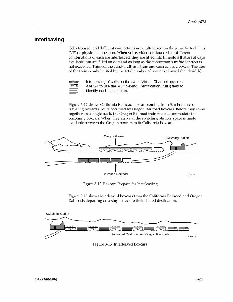
Basic ATM
Interleaving
Cells from several different connections are multiplexed on the same Virtual Path (VP) or physical connection. When voice, video, or data cells or different combinations of each are interleaved, they are fitted into time slots that are always available, but are filled on demand as long as the connection’s traffic contract is not exceeded. Think of the bandwidth as a train and each cell as a boxcar. The size of the train is only limited by the total number of boxcars allowed (bandwidth).
Figure 3-12 shows California Railroad boxcars coming from San Francisco, traveling toward a route occupied by Oregon Railroad boxcars. Before they come together on a single track, the Oregon Railroad train must accommodate the oncoming boxcars. When they arrive at the switching station, space is made available between the Oregon boxcars to fit California boxcars.
Figure 3-12 Boxcars Prepare for Interleaving
Figure 3-13 shows interleaved boxcars from the California Railroad and Oregon Railroads departing on a single track to their shared destination.
Figure 3-13 Interleaved Boxcars
NOTEInterleaving of cells on the same Virtual Channel requires AAL3/4 to use the Multiplexing IDentification (MID) field to identify each destination.
CaliforniaCaliforniaCalifornia California
Oregon RROregon RR Oregon RROregon RROregon RR
Switching StationOregon Railroad
California Railroad 2059-16
CaliforniaCaliforniaCalifornia California Oregon RROregon RR Oregon RROregon RROregon RR
Switching Station
Interleaved California and Oregon Railroads2059-17
Cell Handling 3-21

Basic ATM
The process of interleaving cells on ATM’s switching fabric provides additive bandwidth, just like the boxcars of two trains joined on a single track take up more space on the track. As long as the switch can handle the total cell transfer rate, additional connections to the switch can be made, and the total bandwidth of the system increases accordingly. Likewise, as long as the switching station can handle the amount of train traffic in its switch yard, it can keep adding boxcars.
If a switch can pass cells among all its interfaces at the full rate of all interfaces, it is described as non-blocking. Total throughput of all network connections is found by adding the bandwidth designated to each port by the total amount of ports. For example, an ATM switch with 16 ports, each at 155 Mbps, would require about 2.5 gigabits-per second (Gbps) total throughput to be non-blocking.
3-22 Cell Handling

Chapter 4
Cells
This chapter deals with the formats, organization, and components of ATM cells.
Before a detailed examination of ATM network operation can be learned, a basic understanding of cells and their components must be cemented. While all ATM cells are the same size, and while cells are used for all communications in an ATM network, there are several different classifications for cells that determine how they are treated by the network and what devices may use them.
Cell FormatATM transmits fixed-size cells, 53 bytes in length; a five-byte header, and 48 bytes of data, as shown in Figure 4-1. These cells carry any and all types of data that is passed over an ATM network.
Figure 4-1 ATM Cell
ATM cells are divided into a series of types which identify the treatment they receive from ATM devices. All ATM cells fall within one of these basic cell types.
Header Data Field
5 Bytes 48 Bytes
4-1

Cells
The organization, or format of these cells depends upon the devices that generate them. There are two main cell formats that may be found in a LAN ATM implementation; User-Network Interface, or UNI cells; and Network-Network Interface, or NNI cells. The difference between these two cell formats is the organization and components of the 5-byte header. The sections that follow identify and discuss the different types and formats of cells and the parts of each format’s cell header.
Types of ATM Cells
ATM categorizes four types of cells that have specific purposes assigned to each of them by the ATM and Physical layers: Assigned Cells, Idle Cells, Valid Cells and Invalid Cells. Sources, destinations, and intermediary devices such as switches respond to each type of cell differently. The following sections describe each type of cell:
Assigned CellsAssigned cells in the ATM Layer provide the service to the Medium Access Control layer in the OSI model, transporting the higher level packet data units that carry actual traffic.
Idle CellsIdle cells are inserted or extracted by the Physical Layer for the purposes of adapting the data field capacity. They are also referred to as unused, unassigned, or fill cells. They separate cells, provide receiver synchronization (byte alignment), and reserve bandwidth for another channel (i.e., occupy bandwidth between transmissions). Idle cells do not contain data.
Valid CellsValid cells are cells that do not contain header errors, either through successful transmission or after being corrected by the Physical Layer.
Invalid cells Invalid cells are cells with errors in the header that cannot be corrected. These cells are discarded by operations at the Physical Layer.
Cell Formats
Cells fall into two formats, those used for endstations to switch communications and those used solely for switch to switch communications. The two formats are comprised of markedly similar components. The two cell formats are identified and discussed in the subsections that follow. The components displayed in Figure 4-2 and Figure 4-3 are expanded on in Header Components later in this chapter.
4-2 Cell Format
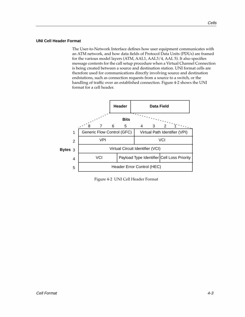
Cells
UNI Cell Header Format
The User-to-Network Interface defines how user equipment communicates with an ATM network, and how data fields of Protocol Data Units (PDUs) are framed for the various model layers (ATM, AAL1, AAL3/4, AAL 5). It also specifies message contents for the call setup procedure when a Virtual Channel Connection is being created between a source and destination station. UNI format cells are therefore used for communications directly involving source and destination endstations, such as connection requests from a source to a switch, or the handling of traffic over an established connection. Figure 4-2 shows the UNI format for a cell header.
Figure 4-2 UNI Cell Header Format
Generic Flow Control (GFC) Virtual Path Identifier (VPI)
VPI VCI
Virtual Circuit Identifier (VCI)
VCI Payload Type Identifier Cell Loss Priority
Header Error Control (HEC)
1
2
3
4
5
8 7 6 5 4 3 2 1
Bits
Bytes
Header Data Field
Cell Format 4-3

Cells
NNI Cell Header Format
The Network-to-Network Interface (NNI) defines the standard interface between two network devices such as switches. There are two types of network-to-network interfaces: Private and Public. The specification for the Private NNI has been defined and the Public NNI has not yet been defined. The cell header of the NNI is identical to that of the UNI, with the exception of the Generic Flow Control field. The GFC field is replaced with an extension of the Virtual Path Identifier to allow for a larger number of defined paths. Figure 4-3 shows the NNI header format. Notice that there is no Generic Flow Control (GFC) component.
Figure 4-3 NNI Cell Header Format
Header Components
The following terms define components of a cell header. For brevity, the components of both UNI and NNI formatted cells are discussed in the following section.
Virtual Path Identifier (VPI) The VPI is used to identify the next path of a cell as it passes through a series of ATM switches on its way to its destination. It is important to remember that the VPI has local significance only. It can be thought of as holding the most significant digits, where the VCI holds the least. By coming first in an arriving cell, the VPI gives the receiver a quick look at whether this cell should be passed on or acted upon.
Virtual Path Identifier (VPI)
VPI VCI
Virtual Circuit Identifier (VCI)
VCI Payload Type Identifier Cell Loss Priority
Header Error Control (HEC)
1
2
3
4
5
8 7 6 5 4 3 2 1
Bits
Bytes
Header Data Field
4-4 Cell Format

Cells
Virtual Channel Identifier (VCI) The VCI is used in conjunction with the VPI to provide physical routing of the cell. The VCI’s 16-bit field identifies a Virtual Channel that has been established by source and destination ATM stations and any intermediate switches. There is no indication in the VCI for the cell’s source and destination. When a Virtual Channel Connection is set up through the ATM call-setup process, the assignment of VCI identifiers for the circuit is complete.
Generic Flow Control (GFC)The GFC can be used to provide local functions, such as identifying multiple users that share a single ATM interface, or directing traffic flow for different grades of service to ensure that users are given fair access to the transmission facilities. This function is only used in Assigned or Idle Cells.
Payload Type Identifier (PTI)The PTI differentiates between cells carrying user data or ATM control information on congestion or management.
Cell Loss Priority (CLP) The CLP determines eligibility for discarding cells. CLP 1 cells are discarded before CLP 0 cells. CLP 1 cells are cells that violate the Quality of Service traffic contract. It also determines whether or not a cell should be discarded in the event of network congestion or other network difficulties by the switch. CLP also indicates which cells to discard first according to their guaranteed throughput. For example, data might have the highest priority because it cannot withstand loss, while voice and video can withstand some loss.
Header Error Control (HEC)The HEC is used for detecting and correcting errors in the cell header. The purpose of protecting the header is to prevent a cell being delivered where it did not belong. Without this protection, a cell might arrive in the wrong destination with an apparently good address that would cause it to be reassembled into a frame. An extra cell causes an error in the received information frame, forcing it to be discarded. Higher level error correction then has to retransmit the frame, needlessly adding to traffic volume and delay. HEC is also used for cell delineation, one-bit error correction, and multiple bit error detection.
Cell Format 4-5

Cells
4-6 Cell Format

Chapter 5
Call Management
This chapter traces the process of setting up and completing an ATM connection, or call.
Before a transaction between two or more endstations on an ATM network can take place, a call must be established. The process of setting up an ATM call is somewhat analogous to the process used to make a call through a telephone network. The sections that follow detail the various stages involved in establishing a call and completing a transaction in a Native ATM network.
Address AssignmentBefore any kind of Virtual Channel Connection can be requested or established, the devices in the ATM network must receive individual ATM addresses. The ATM Forum, in an effort to simplify the process of station configuration, has defined a method for stations to automatically request and receive individual ATM addresses. The operation of this address assignment is handled through the Interim Local Management Interface (ILMI).
When an ATM station is first connected to the network, it sends out a specialized management cell to the switch to which it is connected. This management cell contains the MAC address of the station and a request for an ATM address. When the switch receives this management cell, it associates the MAC address of the station with an available ATM address. The switch then sends a management cell to the endstation, informing it of its ATM address. The endstation may now participate in the network.
5-1

Call Management
Most specification-based ATM networks use a Network Service Access Point, or NSAP, structure for ATM addresses. The NSAP structure is defined by the International Standards Organization (ISO), and is implemented in several LAN technologies. NSAP-format ATM addresses are 20 bytes in length, and are divided into five separate fields. The size and content of each field depends on the type of NSAP-format ATM address that the station or switch making the connection request uses. There are currently three different types of NSAP-format ATM addresses: Data Country Code (DCC) ATM Format, International Code Designator (ICD) ATM Format, and NSAP Encoded E.164 Format. The address format or formats supported by a particular LAN ATM switch is decided by the vendor. In many cases, the switch supports multiple address formats that can be selected by the Network Manager at installation.
Call Establishment
Connection Request
Before a set of endstations can communicate in an ATM network, they must establish a call between them. The process of establishing this call begins with a connection request. The connection request is a signal from the initiating station, referred to from this point on as the source station, that notifies the ATM network that a connection is required.
The source station transmits a signal to the ATM switch to which it directly connects. This signal is the connection request. The switch recognizes the connection request because the transmission is marked by the source station with a specific virtual channel identifier and virtual path identifier. The combination of VCI and VPI, that is associated with connection requests, is defined in the ATM specification as VCI=5, VPI=0. Any time an ATM switch receives a UNI-format cell with these values in its VCI/VPI fields from an endstation, it recognizes it as a connection request.
NOTECabletron Systems ATM equipment typically supports ICD addressing as a default format, but can interoperate with any other format.
5-2 Call Establishment

Call Management
A source station’s connection request, or setup message, contained in a cell, is a combination of notification, addressing, and other related information. This includes the destination ATM address and the Quality of Service (QoS) parameters necessary to complete a connection to the intended destination station. If the process is compared to making a telephone call, the connection request is a combination of lifting the switch hook and dialing the telephone number you wish to call.
A signaling message has a special header format and organization that allows the switch receiving it to process the connection request. The header of the cell is identical to all other ATM cells, providing simple VPI and VCI information, Generic Flow Control, and Header Error Check portions. The data field of the cells in the message contain the ATM address or addresses to which the source station wishes to establish a connection.
Once the ATM switch recognizes the UNI-format connection request message sent over several cells from the endstation, the switch returns a call proceeding message to the station and address resolution begins.
Traffic Contracts
Switches and stations in an ATM network enter into agreements regarding the throughput and delay characteristics of a connection before the connection itself is established. This agreement is called a traffic contract. Before a connection can be established, the traffic contract must be successfully negotiated. A full discussion of traffic contracts and the process of negotiating them is provided in Chapter 6, Call Management.
When a switch receives a connection request, it performs an operation called Connection Admission Control, or CAC. A switch performing CAC examines the resources that are available for the link or port through which the connection request came. The requirements given in the connection request cell are compared to the available resources (throughput, delay variation, etc.) of that switch interface. If the switch can support the connection without disrupting the operation of existing, active connections, the switch establishes the connection and notifies the previous switch of the VPI and VCI of the new link. If the switch cannot accept the connection, it blocks the connection process and does not establish the link. If the switch refuses the connection, it generates a release cell and sends it back to the source station or to a previous switch.
Call Establishment 5-3

Call Management
Route Resolution
Route resolution is the process of recognizing the ATM address of the specified destination station or stations for a call and deciding on a path for the connection to follow. The ATM switch reads the data field of the connection request and takes the ATM address from the data field that identifies the destination station that the source station wishes to connect.
In a simple ATM environment, consisting of a series of ATM stations arrayed around a single switch, the process of route resolution is a simple matter of establishing a relationship between two ports. By the time the switch in a simple ATM network has reached the route resolution stage, all Quality of Service and throughput issues for the switch have been satisfactorily resolved.
The ATM switch, already aware of the port that is connected to the destination station and aware of its availability for the new connection, generates a connection request message. This connection request is passed to the destination station and the table of association is built.
At this point, it is the operation of the destination station that determines if the connection is complete. The destination station can accept or deny the connection request based on its own security, Quality of Service, and availability parameters, and either returns an accept message or a release message. The process of call acceptance or refusal is discussed in Acceptance, later in this chapter.
In a network made up of several switches, especially those arranged in a distinct heirarchy, the process of route resolution is somewhat more complex. As switches are activated and deactivated, and as they have their capacity taken up and released by connections, the availability of the network changes. If a switch does not know what routes are available for a connection request, it may waste valuable connection time attempting to make several connections. It is far more efficient for the switch to automatically forward the cell along a valid estimated path to its destination.
The selection of a valid path depends on the switch having reliable and accurate information about the organization and status of the network. The ATM switch needs to understand the entire network organization on some level to forward a connection request to its final destination. The Private Network-Network Interface, or P-NNI specification, details the way this information is obtained and updated by the switch.
The operation of the P-NNI in resolving and establishing routes for cell traffic is a detailed and important procedure, that begins with the activation of the first switch in the network. As soon as this switch is plugged in and configured, it begins listening to the network to determine which types of devices are connected to it. If a switch notices that it is connected to another switch, it begins exchanging custom messages that are called P-NNI Topology State Packets (PTSPs). These messages carry information detailing the connections available from each switch, the bandwidth available for those connections, and the probable variation in traffic levels on those connections. Using this information, a switch can build a relatively accurate and detailed snapshot of the network from its last update.
5-4 Call Establishment

Call Management
Since PTSPs take up network capacity that can be used for normal data traffic, they are not transmitted on a particularly frequent basis. When a switch decides that it has experienced a significant change in its ability to provide throughput to new connections, or when a switch is added to or removed from the network, switches send out new PTSPs.
The first switch to receive a connection request in a complex network environment compares the destination address to its own list of known stations. If it is able to find that destination station, it determines a valid path based on the network snapshot it obtained through the receipt of PTSP traffic. This operation is called Generic Connection Admission Control, or GCAC. The GCAC process compares the needs of the connection request cell to the information it has received through PTSP traffic regarding the available links in the network. This first switch compares the throughput and QoS requirements of the requested connection to the reported available throughput and QoS values of the virtual paths in the network. The switch forms an estimated path by tracing a route through the switches between itself and the destination station.
The valid route is determined by the station eliminating all links in its network snapshot that cannot support the requirements of the connection request. The first of these requirements to be examined is the available bandwidth. If a link cannot support the bandwidth characteristics specified in the connection request, it is no longer considered. The switch then performs an examination of the remaining links to determine one or more shortest paths.
The group of shortest paths is further reduced by examining reported delay and other specific aspects of each link. When this operation is performed, the switch can choose a valid route through the network for the connection request to follow.
When the first switch determines a valid route through the network using its most recent network snapshot, it prepares a new message. This message replaces the original UNI formatted connection request. The new message, a P-NNI connection request, contains a list of switches that the cell must pass through in order to implement the valid route, as determined by the first switch. Each cell in the P-NNI connection request message contains a field called a Designated Transit List, or DTL.
NOTEThe selection of a valid path does not always equate to the selection of the “best” or fastest path. Processes for determining best paths may be implemented by particular vendors or incorporated in future specifications.
Call Establishment 5-5

Call Management
This new P-NNI connection request is then sent through the first of the links identified in the Designated Transit List to the next switch. The cell travels the valid path throughout the network from switch to switch. Each switch in the valid path treats the connection request message in the same fashion, performing local QoS and CAC checks. The most important exception to this treatment is what happens when a P-NNI connection request moves between associated groups of switches (peer groups). When a connection request is received by a border device, which controls a portion of the access to its own peer group, that border switch performs a new Generic CAC operation, comparing the needs of the switch to the reported condition of its own peer group. The border switch updates the DTL and moves the cell along within its peer group.
Connection Establishment
In a complex, multiswitch network, the process of establishing a connection between two end devices may encompass any number of intermediary switches. With two exceptions — the first and last switches in the final path — all switches in the connection treats the connection request in the same fashion. The method used by the first switch has already been discussed (Route Resolution, above), and the operation of the final switch will be discussed in Acceptance, below). This section deals with the operation of the intermediary switches in the proposed connection.
When an intermediary switch in a complex switched network receives a P-NNI connection request, it begins by examining the throughput and QoS requirements of the connection being requested. The switch performs a local CAC check to determine if it can support the connection. If it can support this new connection, it accepts the connection request.
When a switch accepts the connection request and establishes a connection, it alters the connection request message. The intermediary switch takes the DTL field from the connection request message and removes the most recently used address from the list of stations to be passed through. The DTL field is put back into a P-NNI connection request cell and sent on to the next switch in the list.
As the connection request message is passed forward from switch to switch, associations between the switches are built. Each switch’s connection table recognizes and identifies the virtual channels and paths associated with the Virtual Channel Connection that is being established.
Since there is a short delay involved in the process of setting up a multiswitch VCC, it is possible that a link in the valid path suggested by the first switch is no longer able to support the traffic contract being negotiated by the connection request. It may be that a switch has been shut off, or it may have established additional connections since the most recently passed border switch formulated the acceptable path based on its GCAC operation. If the P-NNI connection request encounters a switch in the valid path that refuses the traffic contract, the signal undergoes crankback.
5-6 Call Establishment

Call Management
Crankback is the process of backing the signal up to an earlier switch and attempting to find a new acceptable path to the destination station. The crankback operation sends the connection request back along the path that it traveled. The message is sent back along the virtual channels and virtual paths that were set up to support its connection. When the connection request message is received at the most recent switch that performed a GCAC operation for it and updated the cell’s Designated Transit List, the cell undergoes another GCAC operation by the switch. The hope is that the switch will, by this time, have received new or more current information on the status of the network through the exchange of PTSPs. Once the switch has determined a valid path, the revised DTL is inserted in the connection request and the cell is sent back out toward its destination.
Acceptance
When the final network switch involved in the call receives the P-NNI connection request cell, it recognizes itself as the last station in the DTL field listing and recognizes the ATM address of the destination station. After performing a CAC operation to ensure that the traffic contract requested by the cell can be supported, the switch contacts the destination station.
To communicate with the destination station, the switch must change the format of the connection request cell. The P-NNI format connection request that the switch receives from the network cannot be correctly interpreted by the endstation, that communicates using UNI-format ATM cells. The end switch formats the P-NNI connection request into a UNI connection request similar to the one initially transmitted by the source station and sends this UNI connection request to the destination station.
Call Establishment 5-7
Call Management
The destination station, recognizing the UNI format connection request, examines the traffic contract requirements and chooses to either allow or deny the connection. If the destination station agrees to allow the connection, it replies to the last switch with an accept message. When the switch receives this accept message, it sends the cell back along the existing VCC that was set up by the connection establishment process. When the accept message cell is received by the source station, which initiated the call, that station recognizes that it has a connection and may begin transmitting and receiving data from that connection. From this point on, the switches monitor and support the passing of cells along the VCC. The operations involved in passing cells is described in Switch Operations later in this chapter. The monitoring and control functions performed by the switches are discussed in Chapter 6, Traffic Management.
If the destination station, for whatever reason, refuses to accept the connection, it returns a release message to the last switch. When the last switch receives this release message from the destination station, it sends the message back along the VCC that has been established. As the release message passes from switch to switch, the connections that had been set up by the connection request are eliminated. The bandwidth that had been reserved for the connection is released to the switches and may be used to support additional connections. Releasing connections is discussed in greater detail in Call Tear Down, later in this chapter.
Switch OperationsOnce a call has been established, ATM switches behave like traditional LAN switches, quickly passing cells from one interface to another. Since the connection between the source and endstations has been established, no switch has to know the full path between the source and destination. They simply pass traffic from interface to interface along the established VCC. During the process of call setup, the switch formulated a table of associations called a switch table. The switch table decides how it will act upon cells which are involved in existing calls. The switch table indicates how the switch should pass traffic, identifying each VCC and the Virtual Channels, Virtual Paths, and port numbers of the switch involved in that VCC.
As a cell is received, its VPI and VCI are examined by the switch. The switch compares the combination of VPI and VCI to its switch table. The comparison reveals to which other VPI and VCI the cell should be passed, and what port the cell must be sent out. Once the switch has determined where the cell must go, it changes the VPI/VCI fields of the cell’s header and transmits it out the correct port. The comparison of cells to the switching table are done.
5-8 Switch Operations
Call Management
Figure 5-1 illustrates how cells are relayed by a switch to the next connection on the network. Cells one and two identify the transmissions of two different users who are relaying their cells through a switch they happen to share. Cells one and two arrive on port one of the ATM switch. First, the switch observes the VPI and VCI fields of cell one and discovers that they have a value of six and four, respectively. The switch refers to its switching table to determine what port it should send the cell to next. It learns that when it receives a VPI of six and a VCI of four on port one, it should send the cell to port three, replacing the VPI and VCI fields on cell one’s header with a VPI of two and a VCI of nine. The new values on the VPI and VCI give an address that is necessary to direct cell one to its forward path in the logical connection.
Next, cell two is examined by the switch, and has a VPI of 1 and a VCI of 8. The table directs the switch to assign cell two on port 2 with a VPI of 4 and a VCI of 5 to its forward path in the logical connection.
There is an inverse relationship in the way cells can be transmitted back and forth between a source and destination user because they both use the same point-to-point connection. If the destination user wants to reply to the source user, the destination user simply transmits cells back over the same VC. In doing so, switches relay cell addresses in the reverse order in which they came.
Figure 5-1 shows how this works, using the reverse path in the logical connection. When cell one has a VPI of 2 and a VCI of 9 and comes in on port 3, the table directs the switch to send cell one back to port one with a VPI of 6 and a VCI of 4.
NOTEA switch can determine the next VPI and VCI address because its switching tables were previously constructed by Network Managers who are responsible for mapping switching relay points on Permanent Virtual Channels on LANs or WANs.
NOTEVCI 1-31 is reserved for use by the ATM Forum and should not be used. Current edge devices generally only support VP 0. Some products support a VPI of 0, 1, 2, and 3.
Switch Operations 5-9

Call Management
Figure 5-1 How Cells Are Routed Through a Switch
Switching TableIn Out
Cell 1
Cell 2
Cell 2Port 1
Port 3
Port 2
ATM Switch
6 4
1 8
4 5
Cell 1
2 9
Port VPI VCI Port VPI VCI
1
3
1
2
2
6
4
1
9
4
5
8
Cell
Cell
1
2
ForwardPath
ForwardPath
ReversePath
ReversePath
6 4
2 9
1 8
4 52
1
3
1
2059-18
5-10 Switch Operations

Call Management
Call Tear DownWhen an endstation in an ATM call decides to eliminate the established connection between itself and another ATM endstation, it begins the process of call tear-down. This tear-down process is essentially the opposite of the call setup process. It dissolves the associations set up between connections in the ATM network. The switch capacity that was reserved for the connection is freed for use by new connections. Tearing down, or releasing the call is similar in effect to hanging up a telephone. The activation of the switch hook signals the telephone switches involved in the call that one of the parties involved in the communication is finished, and the lines and switches that had been part of the call may now be used for other calls.
The call tear down message originates from an ATM endstation and operates in a fashion similar to that used to set up a call. The endstation terminating the call transmits a specialized call release message to which the switch to which it is directly attached. This UNI format cell is processed by the switch. If the call being eliminated is a simple one, involving only the endstations and one ATM switch, the switch sends the call release message to all of the stations involved in the call. These stations recognize the end of the call and the switch deletes the association of that call’s VPI/VCI pairs from its switching tables.
In a complex ATM network consisting of a number of ATM switches, the release message must be passed between the switches involved in the call. The initial switch transforms the UNI format call tear down message into a P-NNI format call message cell. This new P-NNI format release cell is passed off to the next switch through the VPI/VCI pair associated with the connection being torn down. Once the switch has sent the release message, it deletes the VPI/VCI pair association from its switch table and updates its current capacity information.
As the connection release message passes through the network from one switch to the next, it releases the connection or “burns its bridges” behind it. After a connection is released and eliminated, the capacity of this connection is freed for future connections or made available for certain types of existing connections.
Call Tear Down 5-11

Call Management
5-12 Call Tear Down

Chapter 6
Traffic Management
This chapter describes the metrics and operations used by ATM networking devices to control the flow of cells over the network and ensure effective network utilization.
To ensure ATM transmissions receive the network capacity and services they require, the ATM networking technology incorporates a number of traffic control methods. Some of these traffic control processes are negotiated at the time a connection is set up. Others keep watch over an ATM connection to ensure that the connection and the associated number of cells do not exceed the amount of allocated network capacity.
Quality of Service ParametersThe basic method of ATM traffic management is the implementation and use of Quality of Service, or QoS measures. These measurements indicate various levels and types of treatment of network communications. The Quality of Service category that a particular connection requires from the network is dictated by the application or applications which participate in the connection. For example, an exchange of data between a file server and a workstation typically has different network requirements than those of a real-time video conference communication.
The QoS needed by a connection is negotiated at the time the connection is requested. The ATM end station wishing to connect to the ATM network places QoS requirements in the ATM connection request cell used to attempt to set up a connection. If any ATM switch in a path between the requesting station and its destination station cannot support a connection meeting the characteristics of that QoS, that switch does not allow the connection.
NOTEQoS parameters for a PVC are established by the Network Manager during the configuration of the PVC.
6-1
Traffic Management
Quality of Service parameters spell out the speed, dependability, and accuracy of a connection. When a Switched Virtual Channel is established, the switch or switches involved in the connection configure a number of service measures, or QoS parameters. Four parameters of QoS have been identified by the ATM Forum: cell delay variation, peak and average cell transfer delay, and cell loss ratio. There are other QoS parameters, involving the number of errors a connection has experienced and how often a cell has misinserted. The four most important QoS parameters, both negotiated and non-negotiated, are defined and discussed below.
Peak-to-Peak Cell Delay Variation (CDV)Peak-to-Peak Cell Delay Variation, which may be called “cell jitter”, is a measure of the variation in amounts of delay experienced by cells passing through ATM devices in the network. A low CDV indicates that the delay experienced is almost always the same for every cell, while a high CDV can indicate vast changes in delay duration over a connection. CDV is typically measured in microseconds (µs). While data exchanges are typically quite tolerant of CDV, multimedia applications such as voice or video communications require specific windows of CDV from the network.
Maximum Cell Transfer Delay (Max CTD)Maximum Cell Transfer Delay is the highest amount of delay a transmitted cell or stream of cells experiences while being processed by a switch. The Max CTD measures the delay that is caused by the operation of the switch handling the cell. Max CTD typically rises as a switch nears its maximum capacity. Max CTD is the highest amount of delay anticipated for any connection through a switch, and typically reflects the highest possible amount of network traffic.
Mean Cell Transfer Delay (Mean CTD)Mean Cell Transfer Delay is the average of Cell Transfer Delay measurements for the switch or switch port in question. Mean CTD is the expected usual amount of delay for any connection made through the switch.
Cell Loss Ratio (CLR)The Cell Loss Ratio measures the reliability of a single ATM link. The CLR parameter provides an estimate of how many cells are likely to be dropped by an ATM network over time. Cells may be lost or dropped due to excessive congestion at the ATM switches or by problems with physical media segments. The acceptable CLR for a particular connection is dependent upon the applications using the connection and the operating speed of the network.
Cell Error Ratio (CER)The Cell Error Ratio is a measure of the accuracy of an ATM connection. The CER parameter offers an estimate of the percentage of cells that are likely to arrive at their destination with some form of error, but not be dropped. Cell errors may be caused by factors such as defective media or improperly operating switches or error-checking.
6-2 Quality of Service Parameters
Traffic Management
A number of other metrics exist, but they are not negotiable by sources and have little impact on the operation of most ATM LAN equipment.
Traffic ParametersLike the Quality of Service (QoS) parameters described in the previous section, ATM also incorporates several traffic parameters that indicate different treatments and handling characteristics of traffic.
While the QoS Parameters describe the service capabilities of a link, the following traffic parameters describe the special needs of various individual connections or types of connections.
Peak Cell Rate (PCR)Peak Cell Rate is the maximum amount of cell traffic that a source is allowed to maintain. Sources typically negotiate their expected Peak Cell Rate during connection request, and the switch or switches in the network that support the connection place this limit on the traffic they receive.
Sustainable Cell Rate (SCR)The Sustainable Cell Rate is a traffic parameter that defines the average rate of cell transmission that a source is allowed to maintain.
Maximum Burst Size (MBS)Maximum Burst Size is a parameter that is closely related to Peak Cell Rate. The Maximum Burst Size defines the number of consecutive cells that a source is allowed to send when it operates at its peak cell rate.
Minimum Cell Rate (MCR)The Minimum Cell Rate parameter indicates the absolute minimum number of cells per unit of time that the ATM connection from source to destination must provide. The switches in the connection cannot allow capacity to drop below that minimum cell rate. The Minimum Cell Rate is used exclusively for Available Bit Rate service for bursty data.
NOTETraffic parameters are determined before a connection is made. In the case of a PVC, these parameters are decided and configured by the Network Manager when the PVC is established.
Traffic Parameters 6-3

Traffic Management
Cell Delay Variation Tolerance (CDVT)The Cell Delay Variation Tolerance parameter is a network descriptor used to measure delay jitter and cell clumping encountered by cells in the network when several virtual channels are multiplexed on a single connection. During the call setup procedure, a CDVT descriptor is added to the source traffic descriptor, containing the Peak Cell Rate (PCR), Sustainable Cell Rate (SCR) and Maximum Burst Size (MBS), and the Minimum Cell Rate (when the Available Bit Rate service is used). The CDVT is a traffic parameter that ensures the proper resource allocation and Quality of Service (QoS) for a connection by working together with the PCR and SCR to ensure that cells experiencing delay due to multiplexing effects, conform to their traffic descriptors.
Classes of ServiceATM networks carry five types of traffic: Constant Bit Rate (CBR), real-time Variable Bit Rate (rt VBR), non-real-time Variable Bit Rate (nrt VBR) Available Bit Rate (ABR), and Unspecified Bit Rate (UBR). These different types of traffic cover the requirements of several categories of ATM communication.
The types of traffic, that fall under the category classes of service, are decided by the combination of QoS parameters and traffic parameters that each particular connection in the ATM network requires. The combination of requirements leads differing types of ATM network communications to fall into one of these five categories.
Constant Bit Rate (CBR)Constant Bit Rate is a service designed for non-bursty applications that need constant bandwidth allocation and fixed timing requirements such as audio and video traffic. To handle this traffic, the ATM network can act as a dedicated channel by providing a sustained amount of bandwidth, low latency, and low cell-delay variation. A CBR link is one in which the Peak Cell Rate is constant and the Cell Delay Variation Tolerance is extremely low.
CBR traffic takes priority over all other types of traffic, and is guaranteed to receive the Peak Cell Rate that the connection requested for the duration of the connection, provided that all switches in the path can support that PCR.
Figure 6-1 Time vs. Bandwidth for CBR Transmission
Constant Bit Rate
Time
BandwidthPeak Cell Rate (PCR)
2059-19
6-4 Classes of Service
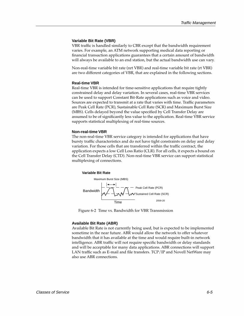
Traffic Management
Variable Bit Rate (VBR) VBR traffic is handled similarly to CBR except that the bandwidth requirement varies. For example, an ATM network supporting medical data reporting or financial transaction applications guarantees that a certain amount of bandwidth will always be available to an end station, but the actual bandwidth use can vary.
Non-real-time variable bit rate (nrt VBR) and real-time variable bit rate (rt VBR) are two different categories of VBR, that are explained in the following sections.
Real-time VBRReal-time VBR is intended for time-sensitive applications that require tightly constrained delay and delay variation. In several cases, real-time VBR services can be used to support Constant Bit-Rate applications such as voice and video. Sources are expected to transmit at a rate that varies with time. Traffic parameters are Peak Cell Rate (PCR), Sustainable Cell Rate (SCR) and Maximum Burst Size (MBS). Cells delayed beyond the value specified by Cell Transfer Delay are assumed to be of significantly less value to the application. Real-time VBR service supports statistical multiplexing of real-time sources.
Non-real-time VBRThe non-real-time VBR service category is intended for applications that have bursty traffic characteristics and do not have tight constraints on delay and delay variation. For those cells that are transferred within the traffic contract, the application expects a low Cell Loss Ratio (CLR). For all cells, it expects a bound on the Cell Transfer Delay (CTD). Non-real-time VBR service can support statistical multiplexing of connections.
Figure 6-2 Time vs. Bandwidth for VBR Transmission
Available Bit Rate (ABR) Available Bit Rate is not currently being used, but is expected to be implemented sometime in the near future. ABR would allow the network to offer whatever bandwidth that it has available at the time and would require built-in network intelligence. ABR traffic will not require specific bandwidth or delay standards and will be acceptable for many data applications. ABR connections will support LAN traffic such as E-mail and file transfers. TCP/IP and Novell NetWare may also use ABR connections.
Variable Bit Rate
Time
BandwidthPeak Cell Rate (PCR)
Sustained Cell Rate (SCR)
Maximum Burst Size (MBS)
2059-20
Classes of Service 6-5

Traffic Management
Figure 6-3 Time vs. Bandwidth for ABR Transmission
Unspecified Bit Rate (UBR)The Unspecified Bit Rate service category is a “best effort” service with no guarantees and is intended for non-critical applications, that do not require tightly constrained delay and delay variation or a specified Quality of Service (QoS). UBR sources are expected to transmit non-continuous bursts of cells and a high degree of statistical multiplexing among sources.
Figure 6-4 Time vs. Bandwidth for UBR Transmission
Traffic ManagementAlthough a switch should never accept more connections or traffic than it can handle, there are opportunities for end systems to take unfair advantage of the switches once connections are in place. If traffic increases beyond the maximum that a switch or network can provide, cells will begin to get lost in the shuffle. Without a policy for managing the flow of traffic and handling possible overabundances, cells could be dropped without regard to their importance. In order to combat the possible disruption to network operations due to excessive traffic, a series of traffic controls and management functions have been incorporated in the ATM specifications. Two of the most important traffic controls are traffic shaping and traffic policing, discussed below.
Available Bit Rate
Bandwidth
Time
Peak Cell Rate (PCR)
Minimum Cell Rate (MCR)
2059-21
2059-22
Unspecified Bit Rate
Bandwidth
Time
6-6 Traffic Management

Traffic Management
Traffic Shaping
The first form of traffic management is an attempt to avoid problems on the ATM network by dealing with them at the source: the source station. The shaping process attempts to force ATM traffic into a particular envelope or set of boundaries which can be easily handled by the switches in the network. Shaping helps to ensure that data meets the traffic contract negotiated during call establishment.
Shaping is a process that happens at a source station, such as a workstation, ATM to legacy LAN switch, or router. By taking this proactive measure before ATM traffic is sent to the network, the traffic shaping function aims to reduce network congestion and minimize the need for the reactive traffic policing function, discussed later.
Often the traffic shaping process smooths out the peaks in a source station’s transmission rate, shifting traffic into a buffer or series of buffers and feeding them out to the ATM network. This “flattening” of the peaks in a transmission series helps the ATM network operate efficiently and helps to minimize errors due to congestion.
Traffic smoothing also changes the transmission aspects of the station to more closely match the needs of the VCC. After flattening out peaks, the traffic shaping process may use the buffered over-transmission to fill in low spaces. It may also attempt to keep the traffic rate as close as possible to the Sustainable Cell Rate (SCR) that was negotiated for the connection.
Traffic Policing
Traffic policing helps enforce the traffic contract. It monitors the number of cells received by a given interface and compares the measures it obtains to the traffic contract decided upon for that connection. While traffic shaping attempts to prevent problems before they impact the network, policing is designed to protect the network from illegal traffic.
The policing function punishes any traffic that does not conform to its traffic contract. Since the switch, for example, agreed on a specific maximum rate for each connection, and does not promise throughput that it cannot provide, the policing function may mark transmitted cells that exceed this maximum rate. End stations may not meet their traffic contract due to poor operation or internal errors.
When cells that do not meet the traffic contract are received, the policing function tags the Cell Loss Priority (CLP) field, changing the cell from a 0 to a 1, indicating that the cell can be dropped by a switch. Any time a switch is running out of resources or capacity, and receives a cell with a CLP of 1, it can drop the cell without having to notify any party involved in the communication.
Traffic Management 6-7

Traffic Management
6-8 Traffic Management

Chapter 7
ATM in the LAN
This chapter shows how ATM technology is implemented into legacy LANs using the LAN Emulation protocol.
Few users will implement ATM if it does not provide connectivity to their existing network. This is an important issue to consider because large numbers of legacy LANs and WANs exist in business, government, and public and private institutions. The key to ATM’s success is its ability to work between different technologies using the LAN Emulation protocol.
Adapting ATM to Connectionless LANsBefore discussing how the LAN Emulation protocol is implemented between Native ATM and Legacy Local Area Networks, it is important to understand the main difference between the two technologies.
Native ATM or “pure” ATM networks communicate in three well defined steps: connection setup, data transfer, and connection release. In most instances, the end result of a Native ATM connection is a dedicated connection between two network devices such as a source and destination end system or switches on a backbone.
In contrast to Native ATM networks, most legacy Local Area Networks use a shared-medium access method among all attached devices. A protocol procedure organizes the sharing process and allows all network devices to use the medium.
7-1
ATM in the LAN
Connectivity between Native ATM and legacy LANs is accomplished through LAN Emulation protocols. LAN Emulation protocols operate transparently over and through ATM switches, using only standard ATM signaling procedures. ATM switches are also being used as convenient platforms to implement some of the LAN Emulation server components, but are independent of the cell relay operation of the ATM switches themselves.
The LAN Emulation protocol, sometimes referred to by its acronym “LANE,” involves a set of services that run on network devices, such as a bridge, LAN switch, workstation or router. These services help resolve a MAC address with an ATM address necessary to set up a connection across an Emulated LAN to allow the flow of data. The LAN Emulation Protocol procedure uses point-to-point and point-to-multipoint ATM connections over the Emulated LAN to transfer data and control functions such as the LAN Emulation Address Resolution Protocol (LE_ARP).
ATM Connection Types
There are two basic types of ATM topological connections. Point-to-point connections connect two ATM end systems that transmit in one or two directions. Also there are point-to-multipoint connections that connect a single source end system (known as a root) to multiple destination end systems (known as leaves).
With point-to-multipoint connections, cells are copied by ATM switches in the network where connections are split into two or more branches. End systems can copy and send cells to multiple end systems across multiple point-to-point connections too, but in most instances this is done by a switch. Most often, point-to-multipoint connections travel in one direction, allowing the root to transmit to the leaves, but not the leaves to the root, or each other, on the same connection.
The following sections describe in greater detail how data flows from Native ATM to legacy LANs like Ethernet, Token Ring, and FDDI using point-to-point and point-to-multipoint ATM connections.
7-2 Adapting ATM to Connectionless LANs
ATM in the LAN
The Rationale for LAN Emulation
The ATM Forum defines LAN Emulation as the method used to encapsulate data before it is transported across an ATM network. The LAN Emulation protocol uses a client/server relationship to resolve connections between ATM and legacy LAN technologies. This protocol uses servers to control the way connections are resolved between clients that represent ATM and legacy LAN devices.
LAN Emulation defines a Network Layer service interface for Token Ring and Ethernet where data sent across the ATM network is encapsulated in the appropriate Medium Access Control (MAC) frame format. This does not mean that an attempt is made to emulate or interfere with the actual MAC protocol of Ethernet (Carrier Sense Multiple Access/Collision Detection) or Token Ring’s token passing network access method. LAN Emulation simply makes an ATM network look and behave like an Ethernet or Token Ring LAN, but one that operates much faster than the alternative.
ATM and existing network technologies use the same Network Layer protocols to work together because it provides a uniform view of higher layer protocols and applications. No modifications are necessary above the Network Layer to carry out LAN Emulation protocol procedures over an ATM network.
The LAN Emulation protocol mimics a legacy Local Area Network on top of an ATM network. The LAN Emulation protocol defines IEEE 802.3 Ethernet and IEEE 802.5 Token Ring as the types of legacy networks to be emulated. FDDI frames must be translated to an Ethernet or Token Ring frame type, before being converted into ATM cells.
LAN Emulation Function and DeploymentThe basic goal of LAN Emulation is for connection-oriented ATM technology to function with an existing connectionless LAN technology such as Ethernet. It is important to recognize the basic differences between a connectionless networking technology like Ethernet and a connection-orientated networking technology like ATM to understand how they work together.
A connectionless network technology like Ethernet uses broadcasts to resolve destination MAC addresses. Since Ethernet is a broadcast network, all stations see all frames, regardless of whether they represent an intended destination. Each station must examine received frames to determine if it is the destination. If so, the frame is passed to a higher protocol layer for appropriate processing. However, a connection-oriented network technology like ATM needs to know the ATM address of a single end system before a source can send data to a destination.
LAN Emulation Function and Deployment 7-3

ATM in the LAN
To support the different media access methods of connection-oriented ATM and connectionless Ethernet, a client/server relationship was offered as the simplest way to bridge the two technologies. To emulate the broadcast or shared media access function of Ethernet, a Broadcast and Unknown Server is used. To assist the connection-making process, a LAN Emulation Server is used to resolve MAC-to-ATM address bindings. Another server is used to help end systems connect to their appropriate servers. The following sections specifically show how the client-server model allows ATM technology to make connections over legacy LANs.
LANE Connectivity
The LAN Emulation protocol defines the way a single Emulated LAN functions. There can be one or more Emulated LANs that are allowed to be on an ATM network at the same time. A single Emulated LAN such as an Ethernet or Token Ring LAN is made up of each of the following components:
LAN Emulation Client (LEC)
A LAN Emulation Client is a software entity that exists on an ATM attached device such as a bridge, workstation with an ATM Desktop Network Interface (DNI) Card, LAN switch, or router. The LAN Emulation Client forwards data, resolves addresses and other control functions, and provides access to any higher layer protocol that interfaces to it.
LAN Emulation Server (LES)
A LAN Emulation Server is identified by a unique ATM address and represents a single Emulated LAN. Topologically, a LAN Emulation Server can be implemented in a centralized or distributed way within an ATM network.
During initialization, a LAN Emulation Server registers a LAN Emulation Client with a unique LAN Emulation Client Identifier, and receives and stores its MAC and corresponding ATM address in its database. The LAN Emulation server uses this same database to help a LAN Emulation Client resolve a destination MAC address with an ATM address.
Broadcast and Unknown Server (BUS)
The Broadcast and Unknown Server is used to flood unknown destination address traffic, and forward multicast and broadcast traffic to LAN Emulation Clients over an Emulated LAN. Whenever the Broadcast and Unknown server learns of a new LAN Emulation Client, it adds it to its point-to-multipoint connection. Point-to-multipoint connections are used from the Broadcast and Unknown Server forward broadcast traffic to all other clients.
7-4 LAN Emulation Function and Deployment

ATM in the LAN
LAN Emulation Configuration Server (LECS)
During the process of initialization, a LAN Emulation Configuration Server registers a LAN Emulation Client’s MAC and ATM address in its database, and gives it the addressing information necessary to make a connection to its LAN Emulation Server and corresponding Emulated LAN. A LAN Emulation Configuration Server logically fits into one administrative domain, that contains several Emulated LANs and their corresponding LAN Emulation Servers.
LAN Emulation OperationAn Emulated LAN’s components and operation are best described in the steps a LAN Emulation Client uses to set up connections. When a LAN Emulation Client comes on line or initializes, it needs to make a connection to the LAN Emulation Configuration Server, LAN Emulation Server, and the Broadcast and Unknown server, in that order, before it can transmit data.
Initialization
When a LAN Emulation Client first comes on line, it gets its own ATM address, and sets up a configuration-direct Virtual Channel Connection to the LAN Emulation Configuration Server. A client can gain access to the LAN Emulation Configuration Server in four different ways. In most instances, the client uses a “well known address,” to set up a connection to the LAN Emulation Configuration Server. This is accomplished using the ATM call setup procedure and a standard, predetermined ATM address.
LAN Emulation Operation 7-5

ATM in the LAN
If the client is unable to locate the LAN Emulation Configuration Server through the “well known address,” it uses a defined Interim Local Management Interface procedure using a predefined Virtual Connection (VPI=0, VCI=16) to set up a connection. If the ATM switch does not know the ILMI procedure, then it uses a well known Permanent Virtual Channel (VPI=0, VCI=17) to connect to the LAN Emulation Configuration Server.
Joining the Emulated LAN
Once the LAN Emulation Client is connected to the LAN Emulation Configuration Server, it makes a request to join an Emulated LAN. This request includes the LAN Emulation Client’s MAC and ATM address, the type of LAN being emulated, maximum frame size, Permanent Virtual Channel mappings and name of the Emulated LAN. When the LAN Emulation Configuration Server receives this information from the LAN Emulation Client, it uses its database to locate the LAN Emulation Client’s LAN Emulation Server and corresponding Emulated LAN.
Once the LAN Emulation Client has the LAN Emulation Server address, it can clear the configuration-direct Virtual Channel Connection to the LAN Emulation Configuration Server. The LAN Emulation Client then sets up a control-direct Virtual Channel Connection to the LAN Emulation Server. The LAN Emulation Server assigns the LAN Emulation Client with a unique LAN Emulation Client Identifier (LECID). The LAN Emulation Client then registers its own MAC and ATM address with the LAN Emulation Server. It may also optionally register any other MAC addresses in the case of a spanning tree bridge. The LAN Emulation Server then sets up a control-distribute Virtual Channel Connection back to the LAN Emulation Client.
Both the control-direct and control-distribute Virtual Channel Connections can be used by the LAN Emulation Client for the LAN Emulation Address Resolution Protocol (LE_ARP) procedure. The LE_ARP is used to request the ATM address that corresponds to a particular destination MAC Layer address that the LAN Emulation Client is using to establish a connection to another end system on the network.
NOTEThe database in the LAN Emulation Configuration Server is accessed by a Network Manager, and managed by Simple Network Management Protocol (SNMP) applications.
NOTEThe LAN Emulation Configuration Server maintains a database of information for each Emulated LAN and its corresponding LAN Emulation Server.
7-6 LAN Emulation Operation

ATM in the LAN
Completing Initialization
A LAN Emulation Client completes the process of joining the network by sending an LE_ARP request to determine the broadcast MAC address of the Broadcast and Unknown Server. The LAN Emulation Server responds to the client’s request and sends it the ATM address of the Broadcast and Unknown Server. The LAN Emulation Client then establishes a point-to-point (Multicast Send) connection to the Broadcast and Unknown Server that, in turn, makes a point-to-multipoint (Multicast Forward) connection to all clients, including the source. The LAN Emulation Client is now ready for data transfer.
Data Transfer
Once a LAN Emulation Client has established its control connections, it can begin participating in data transfer over the network. A LAN Emulation Client receives a MAC frame to forward across a bridge or LAN switch (or a Network Layer packet in the case of Desktop Network Interface Card) during data transfer. A LAN switch or bridge only needs to initiate LAN Emulation procedures if its MAC source address tables indicate that the intended destination address of the packet or frame is not local to the bridge or LAN switch, or if the LAN switch does not know where to send the packet it must find a way to resolve the address to find the proper destination.
Before a data connection can be set up over an Emulated LAN, an ATM address that corresponds to a particular destination MAC address needs to be found. A destination MAC address alone is not enough to set up a connection across an Emulated LAN, but once this destination MAC address is resolved with an ATM address, a path allowing data transfer between a source LAN Emulation Client and destination LAN Emulation Client can be created.
It is possible that the LAN switch or bridge that the LAN Emulation Client is trying to reference for a connection could change its address or set of addresses. This occurs when MAC end systems come up and down, or as particular paths are reconfigured by logical or physical changes in the LAN topology, such as a spanning tree protocol. Because most bridges and switches are self learning, they do not adapt well to connection orientated protocols. For more information on self-learning bridges and switches, refer to the Cabletron Systems Ethernet Guide.
NOTEA bridge or LAN switch switches local traffic between local ports without requiring LAN Emulation Services.
LAN Emulation Operation 7-7
ATM in the LAN
Direct LAN Emulation Client Connections
A unique ATM address identifies each LAN Emulation Client, and can be associated with one or more MAC layer addresses that can be reached through this ATM address. For example, a LAN Emulation Client that has its ATM address associated with one MAC address can be a user’s workstation equipped with one ATM Desktop Network Interface Card. In the case of a bridge or LAN switch, the LAN Emulation Client is associated with all the MAC addresses reachable through its ports. Each user’s workstation in this instance, is attached to one of these ports, having a unique MAC address.
A LAN Emulation Client locally caches any MAC address to the logical association of ATM addresses that it learns through an LE_ARP. A LAN Emulation Client uses its cache of addressing information to reference connections quickly, conserving connection resources and setup latency. This cache is used to check if a connection already exists to one or more end systems, and to match an ATM address to one or more MAC addresses.
If and when a LAN Emulation Client has a packet to send, it looks up the destination MAC address in its cache. If the LAN Emulation Client has a data-direct connection associated with a cached address, it then consults that local cache table and uses the cached mapping, rather than sending out another LE_ARP. Once the cached entry is resolved, data is sent over this data-direct connection.
Cached entries are normally cleared or “aged out” over a configurable time period (typically five minutes). Similarly, data-direct connections are cleared if the connection remains inactive over a configurable period. If a LAN Emulation Client knows the ATM address for a destination MAC address it is trying to reach, it can set up a data-direct connection to its target destination.
Data Transfer Through the LAN Emulation Server
One of the main duties of a LAN Emulation Server is to work with a LAN Emulation Client to resolve unknown addresses. These would be addresses the LAN Emulation Client could not find in its own cache.
To resolve an unknown address, a source LAN Emulation Client prepares an LE_ARP request over its control-direct Virtual Channel Connection, asking the LAN Emulation server for the LAN Emulation Client that has the ATM address that corresponds with the destination MAC address. The LAN Emulation Server tries to fulfill the request by looking in its cache of MAC addresses that correspond to LAN Emulation Client ATM addresses. If the LAN Emulation Server recognizes the association of addresses on the network, it is because some LAN Emulation Clients registered the relevant MAC address.
NOTELAN Emulation Clients maintain the LAN Emulation Server’s cache by registering their MAC addresses.
7-8 LAN Emulation Operation

ATM in the LAN
If the LAN Emulation Server finds the address in its cache, it sends a LAN Emulation Address Resolution Protocol (LE_ARP) reply on the control-direct Virtual Channel Connection back to the source LAN Emulation Client containing the addressing information necessary to make a data-direct connection to the destination LAN Emulation Client.
When the LAN Emulation Server looks at its cache and cannot find the destination MAC address that corresponds to a particular ATM address, it forwards the LAN Emulation Address Resolution Protocol (LE_ARP) request to all the LAN Emulation Clients on the network using a control-distribute Virtual Channel Connection. This solicits a response from LAN Emulation Clients such as a bridge or LAN switch that know the requested MAC address.
The LAN Emulation Server might not have a mapping or logical association of a particular address that is “behind” a bridge or switch. A bridge or LAN switch MAC address may be mapped on the network, but there are instances when the MAC address or addresses of other devices attached to the bridge or LAN switch are not found by the LAN Emulation Server.
Bridges or LAN switches may choose not to register the MAC addresses of the Ethernet users on the other side of them. In these instances, the server needs to re-direct its LE_ARP procedure to get the ATM address of the destination LAN Emulation Client.
To help in this process, a LAN Emulation Client such as a bridge or LAN switch can register with the LAN Emulation Server as a “proxy ” or end system that acts on behalf of other LAN Emulation Clients. The bridge or LAN switch first checks its own cache tables to see whether the requested MAC address directly relates to its own ATM address, or if it is acting as a proxy for a MAC address that can be reached through its ATM address.
The proxy LAN Emulation Client makes an LE_ARP request to the destination LAN Emulation Client. The LAN Emulation Client replies with the requested ATM address over the control-direct Virtual Channel Connection to the LAN Emulation Server. The LAN Emulation Server, in turn, forwards this message to the source LAN Emulation Client, or optionally, on the control-distribute Virtual Channel Connection to all LAN Emulation Clients, so they can learn and cache the particular address mapping and save the results for future LE_ARPs. The source LAN Emulation Client now has the addressing information it needs to set up a data-direct connection to the destination LAN Emulation Client.
NOTEThe LAN Emulation Server may not know the MAC address of a particular bridge or LAN switch because the bridge or LAN switch did not register the MAC addresses on the other side of them. This is because bridge or LAN switch entries are continuously being aged out and re-learned by the LAN Emulation Server cache.
LAN Emulation Operation 7-9

ATM in the LAN
Unknown and Broadcast Connections
The Broadcast and Unknown Server uses a method similar to the flooding procedure used by MAC Layer self-learning bridges for unknown destination frames. When the source LAN Emulation Client cannot find a mapping for a destination MAC address in its local cache, it sends an LE_ARP request to the LAN Emulation Server. If the LE_ARP fails, it then forwards the packet to the Broadcast and Unknown Server. The Broadcast and Unknown Server copies and fowards the packet to all clients that have registered to receive unknown traffic, including the source client, that can receive copies of its own unknown traffic packets.
Each LAN Emulation Client checks the address field of the packets it receives to determine if it is the intended receiver or acting as a proxy for the destination client. If the location of a destination client is known by a proxy client, it responds to the packet by sending an LE_ARP reply containing the ATM to MAC address binding to the source client. When the source client receives this response, it then sets up a data-direct Virtual Channel Connection to the destination client, and is ready to transmit data.
If a response is not received to a Broadcast and Unknown Server’s LE_ARP, the source client will continue to send LE_ARP requests to the Broadcast and Unknown server for the destination client. The source client will be unable to set up a connection to the destination client until a proxy LAN Emulation Client learns the destination client’s location and is able to respond with this information when there are subsequent LE_ARPs requested by the Broadcast and Unknown Server for the address. When the destination client is finally located, the proxy client directly responds to the source client with its ATM to MAC address binding. When the source client receives this response, it then sets up a data-direct Virtual Channel Connection to the destination client, and is ready to transmit data.
Before the data-direct Virtual Channel Connection can be set up, the source client may need to use the LAN Emulation “flush” procedure to ensure that all packets previously sent to the Broadcast and Unknown Server were delivered to the destination. In this mechanism, a control packet is sent down the first transmission path, following the last packet. The second path is not used to send packets until the control packet is received and acknowledged by the destination. This mechanism guarantees a way to meet current LAN standards that require LAN bridges to strictly preserve frame ordering.
The Broadcast and Unknown Server is also used by LAN Emulation Clients for broadcast and multicast packets. Such packets are forwarded by a LAN Emulation Client to the Broadcast and Unknown Server, over its point-to-point connection (Multicast Send). The Broadcast and Unknown Server then fowards the broadcast or multicast packets to all LAN Emulation Clients over its point-to-multipoint connection (Multicast Forward), including the source LAN Emulation Client, that may receive copies of its own broadcast or multicast packets.
7-10 LAN Emulation Operation

ATM in the LAN
Since some LAN protocols cannot tolerate a LAN Emulation Client receiving its own packets, these packets need to be encapsulated and identified. LAN Emulation packet encapsulation requires that all MAC frames be prefixed with the LAN Emulation Client identification. LAN Emulation Clients can then filter all frames in this field that are received from the Broadcast and Unknown Server to ensure that it never receives its own frames.
LAN Emulation and the Spanning Tree Protocol
The LAN Emulation protocol uses a spanning tree algorithm that runs within each Emulated LAN and external networks, such as switch ports bridged to the Emulated LAN, to prevent data loops within the network. This is important for switches that are interconnected by an Emulated LAN, and the external networks connected to switches that are interconnected by external bridges. When the spanning tree protocol is used, LAN Emulation Clients within LAN switches exchange spanning tree data (Bridge Protocol Data Units) between themselves, multicasting through the Broadcast and Unknown Server. Hosts ignore these BPDUs.
If a LAN switch detects a data loop, through spanning tree operation, then it blocks either one of the external ports, or the Emulated LAN port, as necessary, to break the loop. Since the spanning tree algorithm measures links by their bandwidth, generally the protocol tends to favor the LAN Emulation port, and first turns off external ports. Even where the Emulated LAN port is turned off, full connectivity remains possible, by definition, through the external bridged path. The operation of the IEEE 802.1d Spanning Tree Algorithm is discussed in greater detail in the Cabletron Systems Ethernet Technology Overview Guide.
Since LAN Emulation Clients typically cache Address Resolution Protocol information for relatively lengthy periods, there is a danger that LAN Emulation Clients may end up using stale information for excessive periods until the Address Resolution Protocol table entries are aged. While this is happening, information may be sent to invalid connections, because the LAN Emulation Client to which the data-direct connection was originally set up may no longer have any direct connectivity with the intended receiver. This problem can become amplified when many MAC addresses are multiplexed onto the same data-direct connection, as is often the case when existing LAN segments are tied together with an ATM backbone.
LAN Emulation Operation 7-11

ATM in the LAN
For quicker convergence, the LAN Emulation protocol supports LAN Emulation-Topology-Request messages. These are generated by any LAN Emulation Client implementing the spanning tree protocol (typically a LAN switch) when it detects a topology change that triggers a Bridge Protocol Data Unit configuration update message. The LAN Emulation-Topology-Request is sent by the source LAN Emulation Client to the LAN Emulation Server, that then distributes it to all other LAN Emulation Clients. When such a message is received, all LAN Emulation Clients reduce the aging period on their cached Address Resolution Protocol information. This ages the cached information faster, causing the LAN Emulation Clients to more quickly refresh the Address Resolution Protocol information through LE_ARPs that, in turn, generate more up-to-date accessible information.
LAN Emulation Clients do not tear down existing data-direct connections when network reconfiguration is detected, but if no desired MAC addresses are any longer reachable through the connection, the cached LAN Emulation-Address Resolution Protocol information is refreshed and the data-direct connection may fall idle. The LAN Emulation Client then times out the idle connection and clears it.
Control and Data ConnectionsLAN Emulation Clients communicate with each other using a series of ATM connections. LAN Emulation Clients maintain separate connections for data transmission and control traffic. The following sections describe the various control and data connections.
Control Connections
Configuration Direct Virtual Channel Connection This is a bidirectional point-to-point Virtual Channel Connection set up by the LAN Emulation Client to the LAN Emulation Configuration Server. A LAN Emulation Client uses this connection during the initialization process to gather addressing information necessary to make a connection to its LAN Emulation Server and Corresponding Emulated LAN.
Control-Direct Virtual Channel Connection This is a bidirectional Virtual Channel Connection set up by the LAN Emulation Client to its LAN Emulation Server. During the initialization process, a LAN Emulation Client uses this connection to register its MAC and ATM address with the LAN Emulation Server. The LAN Emulation Address Resolution Protocol (LE_ARP) procedure is used over the Control-Direct Virtual Channel Connection to resolve address requests and replies between a LAN Emulation Client and its LAN Emulation Server.
7-12 Control and Data Connections
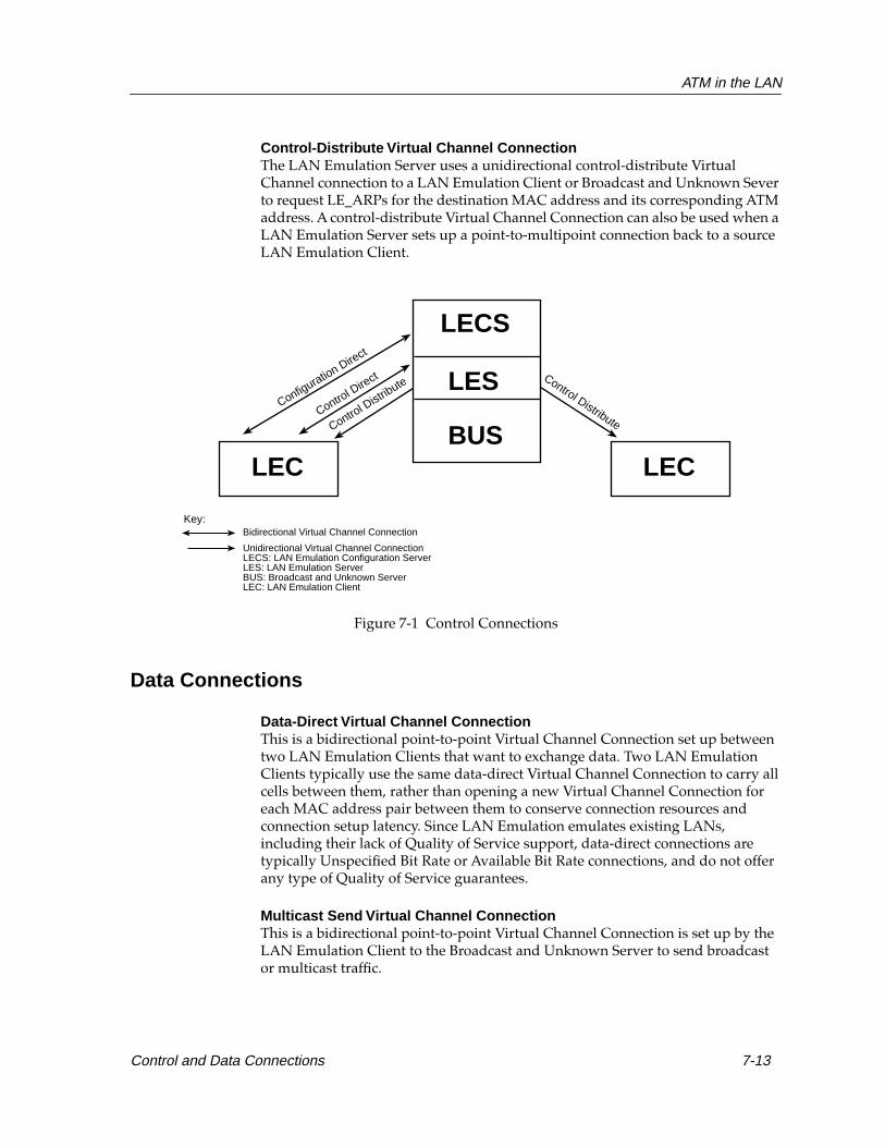
ATM in the LAN
Control-Distribute Virtual Channel Connection The LAN Emulation Server uses a unidirectional control-distribute Virtual Channel connection to a LAN Emulation Client or Broadcast and Unknown Sever to request LE_ARPs for the destination MAC address and its corresponding ATM address. A control-distribute Virtual Channel Connection can also be used when a LAN Emulation Server sets up a point-to-multipoint connection back to a source LAN Emulation Client.
Figure 7-1 Control Connections
Data Connections
Data-Direct Virtual Channel Connection This is a bidirectional point-to-point Virtual Channel Connection set up between two LAN Emulation Clients that want to exchange data. Two LAN Emulation Clients typically use the same data-direct Virtual Channel Connection to carry all cells between them, rather than opening a new Virtual Channel Connection for each MAC address pair between them to conserve connection resources and connection setup latency. Since LAN Emulation emulates existing LANs, including their lack of Quality of Service support, data-direct connections are typically Unspecified Bit Rate or Available Bit Rate connections, and do not offer any type of Quality of Service guarantees.
Multicast Send Virtual Channel ConnectionThis is a bidirectional point-to-point Virtual Channel Connection is set up by the LAN Emulation Client to the Broadcast and Unknown Server to send broadcast or multicast traffic.
LEC
Configuration Direct
Control D
irect
Control D
istribute
Control Distribute
LEC
Unidirectional Virtual Channel ConnectionLECS: LAN Emulation Configuration ServerLES: LAN Emulation ServerBUS: Broadcast and Unknown ServerLEC: LAN Emulation Client
Key:Bidirectional Virtual Channel Connection
LES
LECS
BUS
Control and Data Connections 7-13

ATM in the LAN
Multicast Forward Virtual Channel ConnectionThis is a unidirectional Virtual Channel Connection set up to a LAN Emulation Client from the Broadcast and Unknown Server, and is typically a point-to-multipoint connection, with each LAN Emulation Client as a leaf. This connection distributes broadcast or multicast traffic to all LAN Emulation Clients attached to it.
Figure 7-2 Data Connections
Data Direct
Multicast Forward Multicast ForwardMulticast Send
LEC LEC
Unidirectional Virtual Channel ConnectionLECS: LAN Emulation Configuration ServerLES: LAN Emulation ServerBUS: Broadcast and Unknown ServerLEC: LAN Emulation Client
Key:Bidirectional Virtual Channel Connection
LES
LECS
BUS
7-14 Control and Data Connections
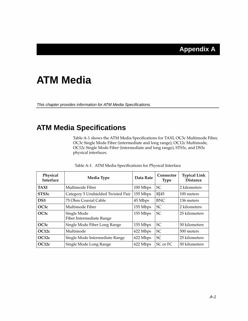
Appendix A
ATM Media
This chapter provides information for ATM Media Specifications.
ATM Media SpecificationsTable A-1 shows the ATM Media Specifications for TAXI, OC3c Multimode Fiber, OC3c Single Mode Fiber (intermediate and long range), OC12c Multimode, OC12c Single Mode Fiber (intermediate and long range), STS3c, and DS3c physical interfaces.
Table A-1. ATM Media Specifications for Physical Interface
Physical Interface
Media Type Data RateConnector
TypeTypical Link
Distance
TAXI Multimode Fiber 100 Mbps SC 2 kilometers
STS3c Category 5 Unshielded Twisted Pair 155 Mbps RJ45 100 meters
DS3 75 Ohm Coaxial Cable 45 Mbps BNC 136 meters
OC3c Multimode Fiber 155 Mbps SC 2 kilometers
OC3c Single ModeFiber Intermediate Range
155 Mbps SC 25 kilometers
OC3c Single Mode Fiber Long Range 155 Mbps SC 50 kilometers
OC12c Multimode 622 Mbps SC 500 meters
OC12c Single Mode Intermediate Range 622 Mbps SC 25 kilometers
OC12c Single Mode Long Range 622 Mbps SC or FC 50 kilometers
A-1

ATM Media
A-2 ATM Media Specifications

Index
AAmerican National Standards Institute
(ANSI) 2-14Asynchronous Transfer Mode
Adaptation Layer 2-11 to 3-12, 3-20AAL1 3-7 to 3-8AAL3/4 3-9, 3-21AAL5 3-11characteristics of 2-12
ATM Layer 2-14ATM network clock 3-7backbones 2-3history of 2-2model 2-10Native ATM 2-2 to 2-4, 5-1, 7-1Physical Layer 2-14specifications 2-14 to 2-15switch operations 5-8 to 5-9switches 5-8workgroups 2-3
ATM address 5-1 to 5-3ATM Forum 2-15, 6-2Available Bit Rate (ABR) 6-5
BBridge Protocol Data Units (BPDUs) 7-11Broadband-Integrated Services Digital
Network (B-ISDN) 2-2Broadcast and Unknown Server (BUS) 7-4,
7-10
CCall proceeding message 5-3Call setup 3-13 to 3-16, 4-5Call tear down 5-11
Cellformat 4-1header 5-3, 5-8header formats
NNI 4-4UNI 4-3
interleaving of 3-21 to 3-22multiplexing 3-17 to 3-20networking 3-5organization 3-6routing through a switch 5-10switching 3-4types
Assigned Cells 4-2Idle Cells 4-2Invalid Cells 4-2Valid Cells 4-2
Cell Delay Variation Tolerance (CDVT) 6-4Cell Error Ratio (CER) 6-2Cell Loss Priority (CLP) 6-7
about 4-5Cell Loss Ratio (CLR) 6-2, 6-5Cell Transfer Delay (CTD) 6-5Classical Internet Protocol 2-3Classical Internet Protocol over ATM 3-11Configuration Direct Virtual Channel
Connection 7-12Connection Admission Control (CAC) 5-3Connection establishment 5-6Connection release message 5-11Connection request 5-2Connection request message 5-4Connectionless networks 3-1 to 3-2Connectionless service 3-9Connection-oriented networks 3-3 to 3-4Connection-oriented service 3-7, 3-9, 3-11Constant Bit Rate (CBR) 2-13 to 3-7
definition of 6-4Control connection types 7-12Control-Direct Virtual Channel
Connection 7-12
Index-1

Index
Control-Distribute Virtual Channel Connection 7-13
Convergence Sublayer (CS) 2-11, 3-9Convergence Sublayer-Protocol Data Unit
(CS–PDU) 3-9, 3-11Crankback 5-6 to 5-7
DData connection types 7-13Data-Direct Virtual Channel Connection 7-13Designated Transit List (DTL) 5-5Desktop Network Interface (DNI) Card 7-4
EEmulated LAN 7-4Ethernet 7-3
FFDDI 7-3Frame relay 3-9Frame-based networking 3-4
GGeneric Connection Admission Control
(GCAC) 5-5Generic Flow Control (GFC) 4-5Getting help 1-3
HHeader Error Control (HEC) 4-5Help 1-3
IInterim Local Management Interface
(ILMI) 5-1International Telecommunications Union-
Telecommunications (ITU-T) 2-14Internet Engineering Task Force (IETF) 2-14Interoperability 2-4
JJitter 3-20
Index-2
LLAN Emulation 2-3, 3-11
data transfer 7-7initialization 7-5operation 7-2, 7-5spanning tree protocol 7-11topology-request messages 7-12
LAN Emulation Address Resolution Protocol (LE_ARP) 7-2, 7-6
LAN Emulation Client (LEC) 7-4, 7-8LAN Emulation Client Identifier (LECID) 7-6LAN Emulation Configuration Server
(LECS) 7-5, 7-6LAN Emulation Server (LES) 7-4, 7-8Local Area Network (LAN) 2-1, 2-3 to 2-4
implementation of 2-3
MMAC address resolution 5-1Maximum Burst Size (MBS) 6-3Maximum Cell Transfer Delay (Max CTD) 6-2Mean Cell Transfer Delay (Mean CTD) 6-2Media specifications A-1Minimum Cell Rate (MCR) 6-3Multicast Forward Virtual Channel
Connection 7-10, 7-14Multicast Send Virtual Channel
Connection 7-10, 7-13Multiplexing 3-9Multiplexing identification (MID) field 3-9,
3-21
NNative ATM see also Asynchronous Transfer
ModeNetwork Service Access Point (NSAP) 5-2Network-to-Network Interface (NNI) 4-4

Index
OOpen Systems Interconnection (OSI)
Model 2-5 to 2-10Application Layer 2-6Data Link Layer 2-7
Logical Link Control 2-8Media Access Control (MAC) 2-8Media Access Control (MAC)
Sublayer 2-8Network Layer 2-7, 7-3Physical Layer 2-8Presentation Layer 2-6Session Layer 2-6Transport Layer 2-7
PPayload Type (PT) 3-11Payload Type Identifier (PTI) 4-5Peak Cell Rate (PCR) 6-3Peak-to-Peak Cell Delay Variation (CDV) 6-2Permanent Virtual Channel (PVC) 3-16, 6-1Physical connections 3-13Physical media specifications
see also Media specificationsP-NNI Topology State Packet (PTSP) 5-4Point-to-multipoint connections 7-2Point-to-point connections 7-2Private Network to Network Interface (P-
NNI) 4-4specification 5-4
Protocol Data Unit (PDU) 4-3Public Network to Network Interface 4-4
QQuality of Service (QoS) 2-12, 3-3, 4-5, 5-5, 6-1,
6-6traffic contract 5-3
RRoute resolution 5-4 to 5-6
SSegment type (ST) 3-9Segmentation and Reassembly (SAR)
sublayer 2-12, 3-9Protocol Data Unit (SAR-PDU) 3-9, 3-11
Sequence counter (SC) 3-7Sequence number (SN) 3-7, 3-9Sequence number protection (SNP) 3-7Simple Network Management Protocol
(SNMP) 7-6Specifications 2-5Standards 2-5Statistical multiplexing 3-17, 6-5Sustainable Cell Rate (SCR) 6-3Switch tables 5-9 to 5-10Switched Multi-megabit Data Service
(SMDS) 3-9Switched Virtual Channels (SVCs) 3-16
TTechnical support 1-3Time division multiplexing (TDM) 3-17Time slots 3-21Token Ring 7-3Traffic control parameters 6-5
Maximum Burst Size (MBS) 6-5Peak Cell Rate (PCR) 6-5Sustainable Cell Rate (SCR) 6-5
Traffic management 6-6Traffic policing 6-7Traffic shaping 6-7Transmission Control Program/Internet
Protocol (TCP/IP) 6-5
Index-3

Index
UUnspecified Bit Rate (UBR)
definition of 6-6User to Network Interface (UNI) 2-15, 4-3
VVariable Bit Rate (VBR) 2-13
definition of 6-5Non-real-time VBR 6-5Real-time VBR 6-5
Virtual Channel (VC) 3-14Virtual Channel Connection (VCC) 3-9,
3-14 to 3-15Virtual Channel Identifier (VCI) 3-14, 5-9
definition of 4-5Virtual connections 3-13Virtual Path (VP) 3-21Virtual Path Identifier (VPI) 3-14, 5-9
definition of 4-4
WWide Area Network (WAN) 2-3
Index-4


![Neutron Discrete Velocity Boltzmann Equation and …radiative heat transfer [30,31], multi-phase flow [32], porous flow [33], thermal channel flow [34], complex micro flow [35,36],](https://img.dokumen.tips/doc/110x75/5fdf780d892f9768791d4093/neutron-discrete-velocity-boltzmann-equation-and-radiative-heat-transfer-3031.jpg)