Embed Size (px)
Citation preview
10 M 078
CP1086-W-1000-KVCP1096-W-1000-KVCP1120-W-1000-KV
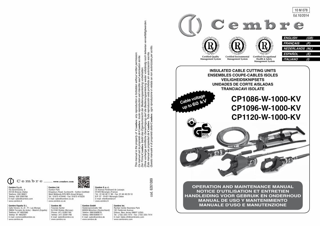
INSULATED CABLE CUTTING UNITS ENSEMBLES COUPE-CABLES ISOLES
VEILIGhEIDSKNIPSETSUNIDADES DE CORTE AISLADAS
TRANCIACAVI ISOLATE
ENGLISh (GB)FRANÇAIS (F)NEDERLANDS (NL)ESPAÑOL (E)ITALIANO (I)
OPERATION AND MAINTENANCE MANUALNOTICE D'UTILISATION ET ENTRETIEN
hANDLEIDING VOOR GEBRUIK EN ONDERhOUDMANUAL DE USO Y MANTENIMIENTOMANUALE D'USO E MANUTENZIONE
Ed.10/2014
This
man
ual is
the
prop
erty
of
Cem
bre:
any
repr
oduc
tion
is fo
rbid
den
with
out w
ritte
n pe
rmiss
ion.
Ce m
anue
l est
la p
ropr
ieté
de
Cem
bre:
tout
e re
prod
uctio
n es
t int
erdi
te s
auf a
utor
isatio
n éc
rite.
Der F
irma
Cem
bre
blei
bt d
as E
igen
tum
srec
ht d
er B
edie
nung
sanl
eitu
ng v
orbe
halte
n.O
hne
vorh
erig
e sc
hrift
liche
Gen
ehm
igun
g da
rf di
e Be
dien
ungs
anle
itung
wed
er v
ollst
ändi
g no
ch te
ilwei
se v
ervie
lfältig
twer
den.
Este
man
ual e
s pr
opie
dad
de C
embr
e. T
oda
repr
oduc
ción
está
pro
hibi
da s
in a
utor
izació
n es
crita
.Q
uest
o m
anua
le è
di p
ropr
ietà
del
la C
embr
e: o
gni r
ipro
duzio
ne é
vie
tata
se
non
auto
rizza
ta p
er s
critt
o.
Cembre Ltd.Dunton ParkKingsbury Road, Curdworth - Sutton ColdfieldWest Midlands B76 9EB (Great Britain)Tel.: 01675 470440 - Fax: 01675 470220E-mail: [email protected]
Cembre S.p.A. Via Serenissima, 9 25135 Brescia (Italia) Telefono: 030 36921Telefax: 030 3365766E-mail: [email protected]
Cembre S.a.r.l.22 Avenue Ferdinand de Lesseps91420 Morangis (France)Tél.: 01 60 49 11 90 - Fax: 01 60 49 29 10B.P. 37 - 91421 Morangis CédexE-mail: [email protected]
Cembre España S.L.Calle Verano, 6 y 8 - P.I. Las Monjas28850 Torrejón de Ardoz - Madrid (España)Teléfono: 91 4852580Telefax: 91 4852581E-mail: [email protected]
Cembre ASFossnes SenterN-3160 Stokke (Norway)Phone: (47) 33361765Telefax: (47) 33361766E-mail: [email protected]
Cembre GmbHHeidemannstraße 16680939 München (Deutschland)Telefon: 089/3580676Telefax: 089/35806777E-mail: [email protected]
Cembre Inc.Raritan Center Business Park181 Fieldcrest AvenueEdison, New Jersey 08837 (USA)Tel.: (732) 225-7415 - Fax: (732) 225-7414E-mail: [email protected]
www.cembre.com
cod.
626
1089
Cable voltage
up to 60 kV
Certified EnvironmentalManagement System
Certified OccupationalHealth & Safety
Management System
Certified QualityManagement System

ITALIANO
– Perrimuovereeventualidepositinelcircuitodell’olio,iltuboflessibileisolantedeveesse- re scollegato dalla pompa. Azionare il pedale di scarico dell’olio e contemporaneamente premereduevolteilpedaleprincipale.Inquestomodovieneeffettuatalapuliziadeica- nali dell’olio nella pompa.
– Effettuarelasostituzionedell’olioinconformitàagliintervallidimanutenzione,documen- tando il momento del cambio olio. A questo scopo il tranciacavi deve essere inviato completo alla Cembre o a personale autorizzato dalla Cembre. La Cembre eseguirà la regolare sostituzione dell’olio e contemporaneamente effettuerà la “prova di collaudo”.
– I componenti danneggiati possono essere sostituiti soltanto con ricambi originali della Cembre.
– La sostituzione di singole parti può essere eseguita solo da personale autorizzato dalla Cembre.
– Per escludere vizi occulti dopo interventi di manutenzione o riparazioni sul tranciacavi, queste operazioni devono essere eseguite dalla Cembre o da personale autorizzato dalla Cembre.
– Pertuttigliinterventidimanutenzioneoriparazioneeseguitisultranciacavièresponsa- bilelapersonachelihaeseguiti.Sevengonoapportatemodifichealprodottopercui questononèpiùidenticoalmanufattocertificato(peres.mancatoutilizzodipezzidi ricambio originali), decade l’autorizzazione all’utilizzo del marchio GS.
– Cembre raccomanda di far eseguire la manutenzione soltanto a personale addestrato. La manutenzione deve avvenire ai seguenti intervalli: 6 anni-utilizzooccasionale-esempio:circa6volteall’anno. 4 anni -utilizzonormale-esempio:circa12volteall’anno. 2 anni -utilizzofrequente-esempio:piùdiunavoltaalmesenelcorsodell’anno Attenzione: Lamanutenzioneeseguitadapersonaleaddestratoèassolutamentene- cessaria secondo BGVA 3 al più tardi dopo 6 anni, indipendentemente dalla frequenza di utilizzo.
– Per la sostituzione dei tubi oleodinamici attenersi alle raccomandazioni del regolmento BGn.BGR237.
In caso di smaltimento, il dispositivo con il suo contenuto (olio idraulico isolante) deve essere portato nei centri di raccolta prescritti dalle normative vigenti.
9. RESA ALLA Cembre PER REVISIONE
In caso di guasto contattare il nostro Agente di Zona il quale vi consiglierà in merito e fornirà le istruzioni necessarie per l’invio dell'unità alla nostra Sede; se possibile, allegare copiadelCertificatodiCollaudoasuotempofornitodallaCembre con l'unità oppure, in mancanza di altri riferimenti, indicare la data approssimativa di acquisto.
661
INDEX1. Use in compliance with the regulations ............................................................ 22. Description of device ........................................................................................ 23. Technical date ................................................................................................... 84. Storage and transportation ............................................................................... 95. Preliminary phases ........................................................................................... 96. Cutting procedure ............................................................................................. 97. In case of breakdown ...................................................................................... 118. Care and maintenance ................................................................................... 139. Return to Cembre for overhaul .......................................................................14
INDEX1. Emploi conforme aux normes ......................................................................... 152. Description du dispositif .................................................................................. 153. Données techniques ....................................................................................... 214. Transport ........................................................................................................ 225. Phases préliminaires ...................................................................................... 226. Procédure de coupe ....................................................................................... 227. Comportement en cas d'anomalie .................................................................. 248. Conservation et entretien ................................................................................ 269. Envoi en revision à Cembre .......................................................................... 27
INDEX1. Gebruik volgens de normen ............................................................................ 282. Beschrijving van de veiligheidsknipset ........................................................... 283. Technische gegevens ..................................................................................... 344. Transport ........................................................................................................ 355. Inleidende fasen ............................................................................................. 356. De knip procedure .......................................................................................... 357. Gedrag in geval van onregelmatigheden ........................................................ 378. Verzorging en onderhoud ............................................................................... 399. Teruggave aan Cembre voor revisie ............................................................. 40
INDICE1. Utilización conforme con las normas .............................................................. 412. Descripción del dispositivo ............................................................................. 413. Datos técnicos ................................................................................................ 474. Transporte ...................................................................................................... 485. Fases preliminares ......................................................................................... 486. Procedimiento de corte ................................................................................... 487. Comportamiento en caso de anomalías ......................................................... 508. Cuidado y mantenimiento ............................................................................... 529. Devolución a Cembre para revisiones .......................................................... 53
INDICE1. Utilizzo conforme alle norme .......................................................................... 542. Descrizione del dispositivo ............................................................................. 543. Dati tecnici ...................................................................................................... 604. Trasporto ........................................................................................................ 615. Fasi preliminari ............................................................................................... 616. Procedura di taglio .......................................................................................... 617. Comportamento in caso di anomalie .............................................................. 638. Cura e manutenzione ..................................................................................... 659. Resa alla Cembre per revisione ................................................................... 66
ENGLISh
FRANÇAIS
NEDERLANDS
ESPAÑOL
ITALIANO
Pag. / Blad

8. CARE AND MAINTENANCE
The Cembre insulated cable cutting units are designed for on site use and thanks to itsconstruction characteristics it is a technical and robust operating device.
To guarantee the reliability of the device for a long period, the following instructions mustbe complied with:
– Regularly remove dirt (dependingon how often it is used) from the cutting head, cylinder,blades and seals using a brush dipped in a liquid detergent. Dry the area carefully.
– Carefully clean the quick couplings and their protection covers each time the unit isused.
– Clean the anchoring screws of the pedal; the pin and blade guide of the cutting head mustbe lubricated with a few drops of oil, to avoid seizing if it is used continuously.
– Every6monthschecktheoillevelinthetankandifnecessarytopup.
Oil top up– Position the pump on a gradient so that the air collects at
the filler in put hole and the oil is able to enter freely.– Release the pedal to make the tank cap easier to access.– Remove the cap and pour in the oil.
The oil must reach the bottom of the threading of the holein the tank.
– Close the oil tank with the cap.The pump is ready for use again.
When topping up alwaysuse the oil specified inpoint 3.Never top up with old orused oil.The oil must be clean.
~250mm
OILÖL
ITALIANOENGLISH
1. UTILIZZO CONFORME ALLE NORME
Il tranciacavi portatile può essere impiegato per tagliare in modo sicuro cavi di rame ealluminio con tensioni nominali fino a 30 kV per i quali non possa essere accertato in modochiaro se sia realizzata e garantita la condizione di assenza di tensione.
Il dispositivo può essere usato sia al coperto che all’aperto anche in caso di precipitazioniin un intervallo di temperatura compreso tra -20°C e +40°C.
Non possono essere tagliati cavi con armatura speciale (peres. cavi per pozzi, cavi aereiautoportanti, cavi marittimi ecc.).
2. DESCRIZIONE DEL DISPOSITIVO
Il tranciacavi comprende essenzialmente i seguenti componenti:– Testa da taglio– Tubo flessibile isolante– Olio isolante– Pompa a pedale– Dispositivo di messa a terra
TESTA DA TAGLIO
TUBO FLESSIBILE ISOLANTE
POMPA
5413
☞
PRIMA DI UTILIZZARE IL TRANCIACAVI ISOLATO, LEGGERE ATTENTAMENTE LEISTRUZIONI PER L’USO SEGUENTI.
LE INFORMAZIONI ChE SONO DI PARTICOLARE IMPORTANZA PER LASICUREZZA TECNICA SONO EVIDENZIATE DA UN SIMBOLO SUPPLEMENTARE SUL MARGINE SINISTRO.
265
ITALIANO ENGLISh
8. CURA E MANUTENZIONE
Il tranciacavi è stato concepito per l’impiego in cantiere e grazie alle sue caratteristiche costruttive risulta essere un dispositivo operativo tecnicamente robusto.
Pergarantire l’affidabilitàdeldispositivoper lungotempo,devonoessereosservate leseguenti disposizioni:
– Eliminareregolarmente(asecondadellafrequenzad’impiego)conunpennelloimmerso indetergenteliquidoeventualiresiduidisporcosullatestadataglio,soprattuttosulci- lindro, sulle lame, nella zona delle guarnizioni e asciugare con cura. – Pulire accuratamente gli innesti rapidi e i relativi tappi di protezione dopo ogni utilizzo.– Levitidifissaggiodelpedale,ilpernoeilguidalamedellatestadatagliodevonoessere lubrificaticonalcunegoccediolio,perimpedirneilgrippaggioincasodiutilizzoconti- nuato.–Ogni6mesicontrollareillivellodell’olionelserbatoiodell’olioesenecessariorabboccare.
Rabbocco dell’olio– Portare la pompa in posizione inclinata, in modo che l’aria si raccolga sul foro di riempimento e l’olio possa essere introdotto agevolmente.– Sganciare il pedale per rendere accessibile il tappo di chiusura del serbatoio– Togliere il tappo di chiusura e introdurre l’olio. L’oliodevearrivarefinoall’estremitàinferioredellafilettatura del foro del serbatoio.– Chiudere il serbatoio dell’olio con il tappo. La pompa è nuovamente pronta per l’uso.
Tappo serbatoio
Per il rabbocco usare sem-pre l’olio indicato al punto 3.Non rabboccare mai con olio usato o vecchio.L’olio deve essere pulito.
OILÖL
Cutting head
FLexibLe insuLated hose
PumP
☞
BEFORE USING ThE INSULATED CABLE CUTTING UNITS, READ ThE FOLLOW INSTRUCTIONS.
VITAL TEChNICAL SAFETY INFORMATION IS ShOWN BY IN ThE LEFT MARGIN.
1. USE IN COMPLIANCE WITh ThE REGULATIONS
These insulated cable cutting units can be used to safely cut copper and aluminium cables with nominal voltage up to 60 kV, where the absence of voltage cannot be guaranteed.
These units can be use both indoors and out, even in wet conditions when the temperature is between -20°C and +40°C.
Donotcutcableswithspecialarmour(e.g.cablesforwells,self-bearingoverheadcables,marine cables etc.).
2. DESCRIPTION OF DEVICE
The cable cutting units comprise the following components: – Cutting head– Flexible insulated hose – Insulating oil– Pedal pump– Earthing device
~250mm
Fig. 1 - Cutting unit components

2.1) Equipotential connection and earthing system
2.1.1) Earthing the pump Between the pump and earth there must be a connection with an earth conductor. For this purpose a Cembre earth cable must be used. This earthing device is availble as anoptionalaccessory(Part.no EK 100).One end of the earth cable must be connected to the earth terminal of the pump, the otherendmustbeconnectedtothesurroundingenvironmentalpotential(e.g.grate,steelsheet, etc.).
2.1.2) Earthing the cutting headIn Germany(seeBGI845)noearthconductormustbeconnectedtothecuttinghead.In some European countries, the earth connection is used to favour the intervention of single phase short circuit protective devices. For countries other than Germany contact the electricity supply utility. Shoulditbeneeded,theearthingdevice,comprisinga5mlongcableandanearthrod,may be ordered from Cembre (Part.noEK 500P).Whatever the case, the earthing device must be approved by Cembre. For earthing the cutting head, proceed as follows: – Unscrew the nut of the earth terminal on the head. –Connectthe5mearthcabletothecuttingheadandtightenthenut.– Tighten the nut hard. – Fully unwind the earth cable.– Ram the earth rod deep into solid ground. – Connect the cable to the earth rod and tighten the nut of the cable terminal.
nut
earthingterminaL
earth CabLe(5 meters)
Cutting head
CabLe Lug
ITALIANOENGLISh
643
– Durante il funzionamento della pompa non si osserva alcun aumento di pressione sul manometro.– Controllare che il pedale di scarico dell’olio non sia premuto.– Azionarepiùvoltebrevementeilpedalediscaricoeverificaresedopol’azionamento questo ritorna automaticamente nella posizione di partenza.–Controllaresec’èsufficienteolio isolantenellapompa(togliere il tappodi rabbocco dell’olio sul serbatoio).– Aggiungereeventualmentedell’olioisolante(utilizzaresoltantoAGIP ITE 360).
– Nonostante la valvola di sicurezza sia scattata e la pressione massima di esercizio sia stata raggiunta, il cavo non è stato tagliato completamente.– Allontanarsi immediatamente dalla zona di taglio.–Mettersiincontattoconl’ufficiodelgestoredellareteeinformarsisucosaèsuccesso.– Azionare il pedale di scarico per 60 secondi.– Togliere la testa dal cavo con un’asta isolante.–Controllareaccuratamentelatestadataglio(peres.condizionedellelame;raccordi); eventualmente eseguire una “fase a vuoto”.– Sel’ufficiodelgestoredellaretenonhasegnalatoeventiparticolari,portareiltranciacavi in un altro luogo ed eseguire nuovamente l’operazione di taglio.
– Durante il funzionamento della pompa è fuoriuscito dell’olio isolante.– Interrompere immediatamente il funzionamento della pompa.– Azionareilpedalediscaricoper60secondiaffinchél’olioisolantechesitrovanelsistema possa tornare nel serbatoio e le lame della testa da taglio possano aprirsi.– Incasodicavointensione,informareimmediatamentel’ufficiodelgestoredellaretee riferire l’accaduto.– Se l’assenza di tensione non può essere accertata con assoluta sicurezza, togliere la testa da taglio dal cavo con un’asta isolante. In nessun caso toccare la testa da taglio con le mani o con oggetti conduttivi!– Se il taglio del cavo deve essere eseguito nonostante il cavo in tensione, effettuare l’operazione con un secondo apparecchio funzionante.– Se la fuoriuscita di olio avviene sul raccordo avvitato del tubo, quest’ultimo può essere serrato.– Sel’anomalianonvieneeliminata,iltranciacavideveessereinviatoallaverifica.

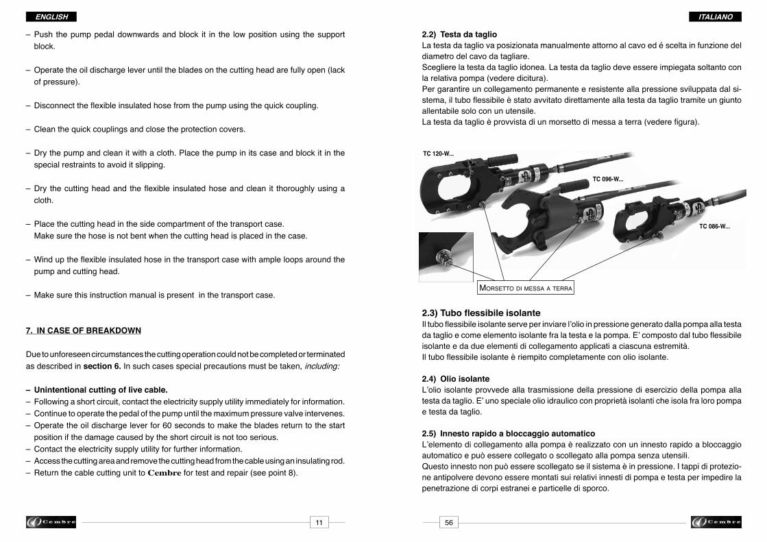
2.2) Cutting headThe cutting head must be positioned manually around the cable to be cut based on the diameter of the cable which has to be cut. Select the appropriate cutting head for the diameter of the cable to be cut and use only withtheassociatedpump(seetext).To guarantee a permanent connection and resistance to the pressure developed in the system,theflexiblehoseisscreweddirectlytothecuttingheadbymeansofacouplingwhich can be loosened only by using a tool. Thecuttingheadisprovidedwithanearthterminal(seefigure).
2.3) Flexible insulated hoseTheflexibleinsulatedhoseisusedtodeliveroilunderpressure,generatedbythepump,to the cutting head and as an insulating element between the head and the pump. Itcomprisesaflexibleinsulatedhoseandconnectorsappliedtoeachend.Theflexibleinsulatedhoseiscompletelyfilledwithinsulatingoil.
2.4) Insulating oilThe insulating oil transmits the operating pressure of the pump to the cutting head. It is a special hydraulic oil with properties which insulate the pump from the cutting head.
2.5) Quick couplersTheflexible insulatedhoseisfittedwithaquickconnector forconnectiontothepumpwithout tools. This coupling cannot be disconnected if the system is under pressure. Theanti-dustprotectioncapmustbeusedonbothhoseandpumpcouplingstopreventingress of dirt or contamination.
ITALIANO ENGLISh
463
– Premereinbassoilpedaledellapompaebloccarlonellaposizioneinferioreconilsup- porto di bloccaggio.
– Azionareilpedalediritornodell’oliofinoall’aperturacompletadellelamesullatestada taglio(condizionediassenzadipressione).
– Scollegareiltuboflessibileisolantedallapompaagendosull’innestorapido.
– Pulire gli innesti rapidi e chiuderli con i tappi di protezione.
– Asciugare la pompa e pulirla con un panno. Collocare la pompa nella custodia di trasporto e bloccarla negli appositi fermi per evitare scivolamenti.
– Asciugarelatestadataglioeiltuboflessibileisolanteepulirliaccuratamenteconun panno.
– Adagiare la testa da taglio nello scomparto laterale della custodia di trasporto. Verificarecheiltubononvengapiegatoquandolatestadatagliovienedepositatanella custodia.
– Avvolgereiltuboflessibileisolantenellacustodiaditrasportoconunampioraggioattorno alla pompa e alla testa da taglio
– Verificarelapresenzadelmanualed’istruzioniperl’operatorenellacustodiaditrasporto.
7. COMPORTAMENTO IN CASO DI ANOMALIE
A causa di condizioni imprevedibili, l’operazione di taglio potrebbe non terminare come descritto nella sezione 6. In questi casi è necessario adottare precauzioni speciali.Ecco di seguito alcune regole di comportamento:
– Accidentalmente viene tagliato un cavo in tensione.–Dopolacomparsadiuncortocircuito,mettersiincontattoimmediatamenteconl’ufficio del gestore della rete per ottenere informazioni a riguardo.–Continuareadazionareilpedaledellapompafinoall’interventodellavalvoladimax. pressione.– Azionareilpedalediscaricodell’olioper60secondiperfartornarelelamenellaposi- zione di partenza se i danni causati dal corto circuito non sono troppo gravi.–Contattarel’ufficiodelgestoredellareteeinformarsisuulteriorieventi.– Accedere alla zona di taglio e togliere la testa dal cavo con l’ausilio di un’asta isolante.– Inviareiltranciacaviperunamanutenzioneeunaverifica(vederepunto8).
earth terminaL
TC 120-W...
TC 096-W...
TC 086-W...

05
06
04
01
02
03
07
08
2.6) PumpThe operating pressure required for cutting the cable is generated in the pump. The pump is operated by means of a foot pedal.
Fig. 2 - Pump components
01 - Pump base 05 - Pedal return spring 02 - Oil discharge lever 06 - Manometer 03 - Operating pedal 07 - Earth connection terminal 04 - Pedal block support 08 - Hydraulic quick coupler
The oil discharge pedal enables the return of the insulating oil to the pump tank and is used to open the blades of the cutting head on termination of the cutting operation.
The manometer shows the operating pressure present in the system.Thepressurefieldwithredbackgroundrepresentsthemaximumacceptableoverpressureoperating limit which cannot be exceeded. On reaching the maximum allowed operating pressure, the maximum pressure valve inside the pump stops any further increase in pressure.
The earth connection terminal on the base of the pump enables the connection of an earthing cable. To avoid the danger of tension gradients, the pump must be connected to theenvironmentpotential(grate,steelsheet,etc.).
ITALIANOENGLISh
625
– Srotolarecompletamenteiltuboflessibileisolante.
– Posizionare la pompa alla massima distanza possibile dal punto di taglio e collegarla altuboflessibileisolante.
– Scegliereilluogodiposizionamentodellapompainmodocheiltuboflessibileiso- lante possa essere posato “a zig zag” sul terreno. Questaprecauzioneserveacompensarel’accorciamentodeltuboduranteilfun- zionamento della pompa.
–Qualorapermotiviambientalinonpossaessererispettataladistanzaminimadi10mdal luogoditaglio,sononecessariealtremisureprecauzionali(peres.terrapieniopareti protettive) per proteggere l’operatore del tranciacavi da un possibile arco elettrico dovuto a un corto circuito.
–Qualorasussistailpericolodigradientiditensione(dalpuntoditaglioallapompa),la pompapuòesserecollegataallaterraattraversoilmorsettoditerraeilconduttorespe- cificoinmododarealizzareuncollegamentoequipotenziale.
– Prenderecontattoconl’ufficiodelgestoredellarete.
– Controllare che nessuno sosti nella zona di pericolo.
– Eseguire l’operazione di taglio azionando la pompa a pedale. Posizionare il piede al centro, sulla staffa del pedale. Duranteilfunzionamentodellapompaosservarel’andamentodellapressionesulma- nometro.
–Durantel’operazioneditagliosigeneraunlentoaumentodellapressione,chepuòas- sumere andamenti diversi a seconda del tipo di cavo. – E’necessariocontinuareadazionarelapompafinchénonsaràraggiuntalaso- vrappressione di esercizio massima ammessa e si avvertirà li scatto la valvola di sicurezza.
– Azionare il pedale di ritorno dell’olio della pompa e mantenerlo premuto per circa 60 secondiaffinchélelamedellatestadatagliopossanoritornareautomaticamentenella posizione iniziale.
– Informarel’ufficiodelgestoredellaretechel’operazioneditaglioèstataeseguita.Se dall’ufficiodelgestoredellaretenonvengonosegnalatieventiparticolari,sipuòaccede- re alla zona di taglio.
– Accedere alla zona di taglio e togliere la testa dal cavo afferrandola dall’impugnatura di sostegno.
☞
☞
☞

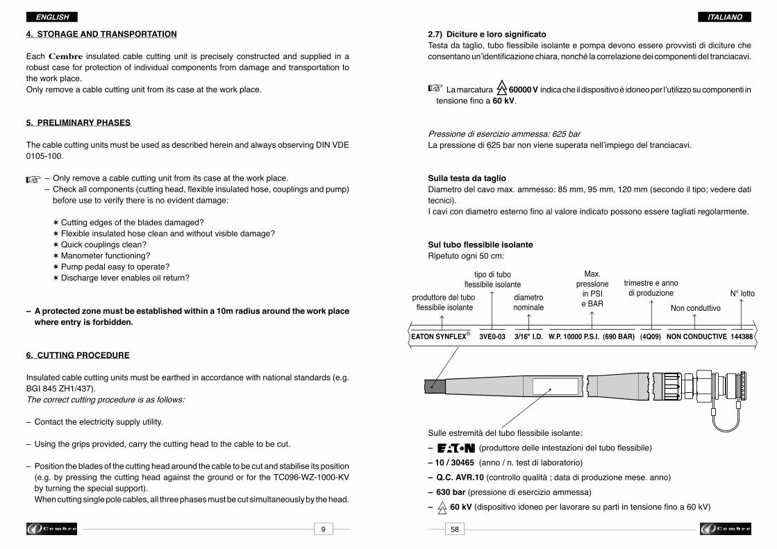
2.7) MarkingsCuttinghead,flexibleinsulatedhoseandpumpmustbeprovidedwithwordingwhichenablesbothclearidentificationandthecorrectcorrelationofcablecuttingunitcomponents.
The marking 60000 V indicates that the device is suitable for use on cables with voltage up to 60 kV.
PermissibleOperatingpressure:625barThepressureof625barisnotexceededintheuseofthecablecuttingunits.
On the cutting headMaximumdiameterofthecablepermissible:85mm,95mm,120mm(accordingtotype;see technical data).Cables with external diameters up to the indicated values can be cut regularly.
On the flexible insulated hose Repeatedevery50cm:
On the guards hose:
– (guardhosemanufacturersmark)
– 10 / 30465 (manufacturedyear/laboratorytestnr.)
– Q.C. AVR.10 (qualitycontrol;manufactureddatemonth.year)
– 630 bar (permissibleoperatingpressure)
– 60 kV(equipmentsuitableforworkingoncablesundervoltageupto60kV)
☞
ITALIANO ENGLISh
661
4. TRASPORTO
Il tranciacavi è stato prodotto con la massima accuratezza ed è fornito in una robusta cu-stodia di trasporto. La custodia protegge i singoli componenti dal danneggiamento durante l’immagazzinamentoeduranteiltrasportofinoalluogodilavoro.Il tranciacavi deve essere prelevato dalla sua custodia soltanto sul luogo d’utilizzo.
5. FASI PRELIMINARI
Il tranciacavi deve essere utilizzato come descritto nelle presenti istruzioni per l’uso.DeveessereosservatalanormaDINVDE0105-100.
– Togliere il tranciacavi dalla custodia di trasporto sul luogo di lavoro. – Tuttiicomponenti(testadataglio,tuboflessibileepompa)devonoesserecontrollati primadell’usoperverificarechenonpresentinodannievidenti:
✶ Taglienti delle lame danneggiati? ✶Tuboflessibileisolantepulitoesenzadannivisibili? ✶ Innesti rapidi puliti? ✶ Manometro funzionante? ✶ Pedale della pompa di facile azionamento? ✶ Pedale di scarico abilita il ritorno dell’olio?
– Nel raggio di 10 m attorno al luogo di lavoro deve essere creata una zona protetta in modo da impedire l’accesso a chiunque.
6. PROCEDURA DI TAGLIO
Perlamessaaterradeltranciacavidevonoessereosservatelenormenazionali(peres.inGermanialaBGI845ZH1/437).La corretta procedura di taglio avviene nel seguente modo:
– Prenderecontattoconl’ufficiodelgestoredellarete.
– Trasportarelatestadatagliotramitel’impugnaturafinoalcavodatagliare.
– Posizionare le lame della testa da taglio attorno al cavo da tagliare e stabilizzarne la posizione(peres.premendosaldamentelatestadatagliosulsuolooppureperiltipo TC096-WZ-1000-KVruotarel’appositopiedinodiappoggio). Nel caso debbano essere tagliati cavi unipolari, le tre fasi devono essere racchiuse contemporaneamente nella testa da taglio.
☞
hose manufacturer
typeofflexibleinsula-ted hose
rated diameter
Max. pressure
in PSI and BAR
quarter and year manufactured serial Nr.
EATON SYNFLEX® 3VE0-03 3/16" I.D. W.P. 10000 P.S.I. (690 BAR) (4Q09) NON CONDUCTIVE 144388
85
PO6000-WZ-KVBenutzenmit Pumpe
Serien-Nr.
TC086-WZ-1000-KVTypKabel. Ø Max. mm
Jahr
625 bar
Made in Italy
60000 V
Zugelassener Höchstdruck
95
PO6000-WZ-KVBenutzenmit Pumpe
Serien-Nr.
TC096-WZ-1000-KVTypKabel. Ø Max. mm
Jahr
625 bar
Made in Italy
60000 V
Zugelassener Höchstdruck
120
PO6000-WZ-KVBenutzenmit Pumpe
Serien-Nr.
TC120-WZ-1000-KVTypKabel. Ø Max. mm
Jahr
625 bar
Made in Italy
60000 V
Zugelassener Höchstdruck
PO6000-WZ-KVDOPPELKOLBENHYDRAULIK FUSSPUMPE TYP
625 bar
Serien-Nr. Jahr
ZugelassenerHöchstdruck
TC086-WZ-1000-KV TC096-WZ-1000-KV TC120-WZ-1000-KV
ErlaubteSchneidköpfe
Made in Italy
60000 V
ITALIANOENGLISh
607
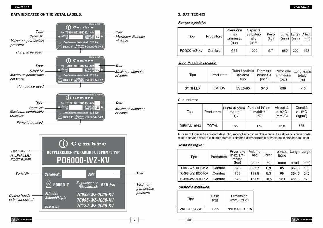
3. DATI TECNICI
Pompa a pedale:
Tipo Produttore
Pressionemax.
ammessa(bar)
Capacitàserbatoio
olio(cm3)
Peso(kg)
Lung.(mm)
Largh.(mm)
Altez.(mm)
Cembre 625 1000 9,7 680 200 163
Tubo flessibile isolante:
Tipo Produttore Tuboflessibile
isolantetipo
Diametro nominale(inch)
Lunghezzatotale(m)
SYNFLEX EATON 3VE0-03 3/16 630 >10
Pressione ammessa (bar)
Olio isolato:
TipoDensitàa15°C(kg/m3)
DIEKAN1640 853
Produttore
TOTAL
Punto di scorri-mento(°C)
-33
Puntodiinfiam-mabilità(°C)
174 12,8
Viscositàa40°C(mm2/S)
Testa da taglio:
Tipo
TC086-WZ-1000-KV
ProduttorePressionemax. am-
messa(bar)
Peso
(kg)
ø max.taglio
(mm)
Lungh.
(mm)
Largh.
(mm)
Volumeolio
(cm3)
TC096-WZ-1000-KVTC120-WZ-1000-KV
CembreCembreCembre
625625625
89,57123,8181,5
6,99,310,5
8595120
369,5394,0481,5
135242175
Custodia metallica:
TipoPeso(kg)
Dimensioni(mm)LxLxH
VALCP096-W 12,6 786x430x175
PO6000-WZ-KV
Incasodifuoriuscitaaccidentalediolio,raccoglierloconsabbiaoterra.Lasabbiaolaterraconta-minate devono essere eliminate tramite il sistema di smaltimento previsto dalle disposizioni locali.
TypeSerial Nr.
Maximum permissible pressure
YearMaximum diameter of cable
Cutting heads to be connected
Serial Nr.
TWO SPEED HYDRAULIC FOOT PUMP
TypeSerial Nr.
YearMaximum diameter of cable
TypeSerial Nr.
YearMaximum diameter of cable
Year
Pump to be used
DATA INDICATED ON ThE METAL LABELS:
Pump to be used
Pump to be used
Maximum permissible pressure
Maximum permissible pressure
Maximum permissible pressure

85
PO6000-WZ-KVBenutzenmit Pumpe
Serien-Nr.
TC086-WZ-1000-KVTypKabel. Ø Max. mm
Jahr
625 bar
Made in Italy
60000 V
Zugelassener Höchstdruck
95
PO6000-WZ-KVBenutzenmit Pumpe
Serien-Nr.
TC096-WZ-1000-KVTypKabel. Ø Max. mm
Jahr
625 bar
Made in Italy
60000 V
Zugelassener Höchstdruck
120
PO6000-WZ-KVBenutzenmit Pumpe
Serien-Nr.
TC120-WZ-1000-KVTypKabel. Ø Max. mm
Jahr
625 bar
Made in Italy
60000 V
Zugelassener Höchstdruck
PO6000-WZ-KVDOPPELKOLBENHYDRAULIK FUSSPUMPE TYP
625 bar
Serien-Nr. Jahr
ZugelassenerHöchstdruck
TC086-WZ-1000-KV TC096-WZ-1000-KV TC120-WZ-1000-KV
ErlaubteSchneidköpfe
Made in Italy
60000 V
ITALIANO ENGLISh
859
3. TEChNICAL DATE
Foot pump:
Type Manufacturer
Maximum permissible
pressure (bar)
Oilreservoircapacity(cm3)
Weight(kg)
Length(mm)
Width(mm)
Height(mm)
Cembre 625 1000 9,7 680 200 163
Flexible insulated f hose:
Type ManufacturerInsulated
hosetype
Nominaldiameter(inch)
Totallength(m)
>10
Permissiblepressure(bar)
Insulating oil:
TypeDensityto15°C(kg/m3)
DIEKAN1640 853
Manufacturer
TOTAL
Meltingpoint(°C)
-33
Flashpoint(°C)
174 12,8
Viscosityto40°C(mm2/S)
Cutting head:
Type
TC086-WZ-1000-KV
ManufacturerMaximum
permissiblepressure(bar)
Weight
(kg)
Max.cuttingdiam.(mm)
Length
(mm)
Width
(mm)
Oilvolume
(cm3)
TC096-WZ-1000-KVTC120-WZ-1000-KV
CembreCembreCembre
625625625
89,57123,8181,5
6,99,310,5
8595120
369,5394,0481,5
135242175
Metal case
TypeWeight(kg)
Dimensions(mm)LxWxH
VALCP096-W 12,6 786x430x175
PO6000-WZ-KV
In the case of accidental oil leak, collect the oil using sand or earth and dispose of only in accordance with local regulations.
TipoNr. matricola
Pressione massima ammessa
Utilizzabile con pompa
AnnoDiametro massimo del cavo
Teste da taglio ammesse
Nr. matricola
POMPA OLEODI-NAMICA A PEDALE A 2VELOCITà
TipoNr. matricola
Pressione massima ammessa
AnnoDiametro massimo del cavo
TipoNr. matricola
Pressione massima ammessa
AnnoDiametro massimo del cavo
Anno
Utilizzabile con pompa
Utilizzabile con pompa
DATI RIPORTATI SULLE TARGhETTE:
Pressione massima ammessa
SYNFLEX EATON 3VE0-03 3/16 630
2.7) Diciture e loro significatoTestadataglio,tuboflessibileisolanteepompadevonoessereprovvistididiciturecheconsentanoun’identificazionechiara,nonchélacorrelazionedeicomponentideltranciacavi.
La marcatura 60000 V indica che il dispositivo è idoneo per l’utilizzo su componenti in tensionefinoa60 kV.
Pressionediesercizioammessa:625barLapressionedi625barnonvienesuperatanell’impiegodeltranciacavi.
Sulla testa da taglioDiametrodelcavomax.ammesso:85mm,95mm,120mm(secondoiltipo;vederedatitecnici).Icavicondiametroesternofinoalvaloreindicatopossonoesseretagliatiregolarmente.
Sul tubo flessibile isolanteRipetutoogni50cm:
Sulleestremitàdeltuboflessibileisolante:–(produttoredelleintestazionideltuboflessibile)– 10 / 30465 (anno/n.testdilaboratorio)– Q.C. AVR.10 (controlloqualità;datadiproduzionemese.anno)– 630 bar (pressionediesercizioammessa)– 60 kV(dispositivoidoneoperlavoraresupartiintensionefinoa60kV)
ITALIANOENGLISh
☞
589
4. STORAGE AND TRANSPORTATION
Each Cembre insulated cable cutting unit is precisely constructed and supplied in a robust case for protection of individual components from damage and transportation to the work place. Only remove a cable cutting unit from its case at the work place.
5. PRELIMINARY PhASES
The cable cutting units must be used as described herein and always observing DIN VDE 0105-100.
– Only remove a cable cutting unit from its case at the work place. – Checkallcomponents(cuttinghead,flexibleinsulatedhose,couplingsandpump) before use to verify there is no evident damage:
✶ Cutting edges of the blades damaged? ✶ Flexible insulated hose clean and without visible damage? ✶ Quick couplings clean? ✶ Manometer functioning? ✶ Pump pedal easy to operate? ✶ Discharge lever enables oil return?
– A protected zone must be established within a 10m radius around the work place where entry is forbidden.
6. CUTTING PROCEDURE
Insulatedcablecuttingunitsmustbeearthedinaccordancewithnationalstandards(e.g.BGI845ZH1/437).The correct cutting procedure is as follows:
– Contact the electricity supply utility.
– Using the grips provided, carry the cutting head to the cable to be cut.
– Position the blades of the cutting head around the cable to be cut and stabilise its position (e.g.bypressingthecuttingheadagainstthegroundorfortheTC096-WZ-1000-KV by turning the special support). When cutting single pole cables, all three phases must be cut simultaneously by the head.
☞
produttore del tuboflessibileisolante
tipo di tubo flessibileisolante
diametro nominale
Max. pressione
in PSI e BAR
trimestre e anno di produzione N° lotto
EATON SYNFLEX® 3VE0-03 3/16" I.D. W.P. 10000 P.S.I. (690 BAR) (4Q09) NON CONDUCTIVE 144388
Non conduttivo

05
06
04
01
02
03
07
08
ITALIANO ENGLISh
2.6) PompaNella pompa viene generata la pressione di esercizio necessaria per il taglio del cavo. La pompa viene azionata dall’operatore agendo sul pe-dale.
Fig. 2 - Componenti della pompa
01 - Basamento della pompa 05 - Molle di richiamo del pedale 02 - Pedale di scarico dell’olio 06 - Manometro 03 - Pedale di azionamento 07 - Morsetto per il collegamento equipotenziale04 - Molla di bloccaggio del pedale 08 -Elementodicollegamento(innestorapido)
Il pedale di scarico dell’olio abilita il ritorno dell’olio isolante nel serbatoio della pompa e viene azionato per aprire le lame della testa da taglio al termine dell’operazione di taglio.
Il manometro indica la pressione di esercizio presente nel sistema.Il campo di pressione con fondo rosso rappresenta il campo limite della sovrappressione di esercizio massima ammessa che non può essere superata.Al raggiungimento della pressione di esercizio massima ammessa, la valvola di max. pressione all’interno della pompa impedisce un ulteriore aumento della pressione.
Il morsetto per il collegamento equipotenziale sul basamento della pompa permette il collegamento di un conduttore di terra. Per prevenire il pericolo di gradienti di tensione, lapompadeveesserecollegataalpotenzialedell’ambiente(griglia, lamieradiacciaioecc.)
1057
– Fullyunwindtheflexibleinsulatedhose.
– Positionthepumpasfaraspossiblefromthecuttingpointandconnectittotheflexible insulated hose. – Placethepumpsuchthattheflexibleinsulatedhosecanbelaid“zigzag”onthe ground. This precaution is to compensate for shortening of the hose while the pump is operating.
– Ifforanyreasontheminimum10mradiusnoentryzonecannotbeestablished,other precautionarymeasuresmustbetaken(e.g.embankmentsorprotectionwalls)toprotect the operator from a possible disturbance arc due to a short circuit.
– Should there be the danger of voltage gradients between cutting head and pump, the pumpcanbeconnectedtoearthusingtheearthterminalandthespecificcablesoas to form an equipotential connection.
– Contact the electricity supply utility.
– Check that nobody enters the danger zone.
– Carry out the cutting operation by operating the pump pedal. Position the foot in the centre of the pedal crank. During operating of the pump, check pressure on the manometer.
–Duringthecuttingoperationthereisaslowincreaseinpressurewhichcanvarydepend- ing on the type of cable.
– Itisnecessarytocontinuetousethepumpuntilthemaximumpermissibleover- pressure is reached and the safety valve is heard to click into action.
–Operatetheoildischargeleverofthepumpandkeepitpressedforabout60seconds so that the blades of the cutting head can automatically return to the start position.
– Inform the electricity supply utility that the cutting operation has been carried out. If they do not warn against any particular events, the cutting zone can be accessed.
– Access the cutting area and rremove the cutting head from the cable using the support grip provided.
☞
☞
☞
ITALIANOENGLISh
2.2) Testa da taglioLa testa da taglio va posizionata manualmente attorno al cavo ed é scelta in funzione del diametro del cavo da tagliare. Scegliere la testa da taglio idonea. La testa da taglio deve essere impiegata soltanto con larelativapompa(vederedicitura).Per garantire un collegamento permanente e resistente alla pressione sviluppata dal si-stema,iltuboflessibileèstatoavvitatodirettamenteallatestadatagliotramiteungiuntoallentabile solo con un utensile.Latestadataglioèprovvistadiunmorsettodimessaaterra(vederefigura).
2.3) Tubo flessibile isolanteIltuboflessibileisolanteserveperinviarel’olioinpressionegeneratodallapompaallatestadataglioecomeelementoisolantefralatestaelapompa.E’compostodaltuboflessibileisolante e da due elementi di collegamento applicati a ciascuna estremità.Iltuboflessibileisolanteèriempitocompletamenteconolioisolante.
2.4) Olio isolanteL’olio isolante provvede alla trasmissione della pressione di esercizio della pompa alla testa da taglio. E’ uno speciale olio idraulico con proprietà isolanti che isola fra loro pompa e testa da taglio.
2.5) Innesto rapido a bloccaggio automaticoL’elemento di collegamento alla pompa è realizzato con un innesto rapido a bloccaggio automatico e può essere collegato o scollegato alla pompa senza utensili.Questo innesto non può essere scollegato se il sistema è in pressione. I tappi di protezio-ne antipolvere devono essere montati sui relativi innesti di pompa e testa per impedire la penetrazione di corpi estranei e particelle di sporco.
5611
– Push the pump pedal downwards and block it in the low position using the support block.
–Operatetheoildischargeleveruntilthebladesonthecuttingheadarefullyopen(lack of pressure).
–Disconnecttheflexibleinsulatedhosefromthepumpusingthequickcoupling.
– Clean the quick couplings and close the protection covers.
– Dry the pump and clean it with a cloth. Place the pump in its case and block it in the special restraints to avoid it slipping.
–Drythecuttingheadandtheflexible insulatedhoseandclean it thoroughlyusinga cloth.
– Place the cutting head in the side compartment of the transport case. Make sure the hose is not bent when the cutting head is placed in the case.
–Winduptheflexibleinsulatedhoseinthetransportcasewithampleloopsaroundthe pump and cutting head.
– Make sure this instruction manual is present in the transport case.
7. IN CASE OF BREAKDOWN
Due to unforeseen circumstances the cutting operation could not be completed or terminated as described in section 6. In such cases special precautions must be taken, including:
– Unintentional cutting of live cable.– Following a short circuit, contact the electricity supply utility immediately for information.– Continue to operate the pedal of the pump until the maximum pressure valve intervenes.–Operatetheoildischargeleverfor60secondstomakethebladesreturntothestart position if the damage caused by the short circuit is not too serious.– Contact the electricity supply utility for further information.– Access the cutting area and remove the cutting head from the cable using an insulating rod. – Return the cable cutting unit to Cembrefortestandrepair(seepoint8).
TC 120-W...
TC 096-W...
TC 086-W...
morsetto di messa a terra
ITALIANO ENGLISh
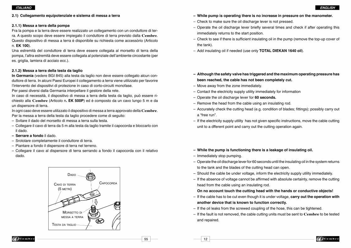
dado
morsetto di messa a terra
Cavo di terra(5 metri)
testa da tagLio
CaPoCorda
– While pump is operating there is no increase in pressure on the manometer. – Check to make sure the oil discharge lever is not pressed. –Operatetheoildischargeleverbrieflyseveraltimesandcheckifafteroperatingthis immediately returns to the start position.–Checktoseeifthereissufficientinsulatingoilinthepump(removethetop-upcoverof the tank). – Addinsulatingoilifneeded(useonlyTOTAL DIEKAN 1640 oil).
– Although the safety valve has triggered and the maximum operating pressure has been reached, the cable has not been completely cut. – Move away from the zone immediately.– Contact the electricity supply utility immediately for information – Operate the oil discharge lever for 60 seconds. – Remove the head from the cable using an insulating rod. – Accuratelycheckthecuttinghead(e.g.conditionofblades;fittings);possiblycarryout a “free run”. – Iftheelectricitysupplyutilityhasnotgivenspecificinstructions,movethecablecutting unit to a dfferent point and carry out the cutting operation again.
– While the pump is functioning there is a leakage of insulating oil. – Immediately stop pumping. –Operatetheoildischargeleverfor60secondsuntiltheinsulatingoilinthesystemreturns to the tank and the blades of the cutting head can open. – Should the cable be under voltage, inform the electricity supply utility immediately. – Iftheabsenceofvoltagecannotbeaffirmedwithabsolutecertainty,removethecutting head from the cable using an insulating rod. On no account touch the cutting head with the hands or conductive objects! – If the cable has to be cut even though it is under voltage, carry out the operation with another device that is known to function correctly. – If the oil leaks from the screwed coupling of the hose, this can be tightened. – If the fault is not removed, the cable cutting units must be sent to Cembre to be tested and repaired.
1255
2.1) Collegamento equipotenziale e sistema di messa a terra
2.1.1) Messa a terra della pompaFra la pompa e la terra deve essere realizzato un collegamento con un conduttore di ter-ra. A questo scopo deve essere impiegato il conduttore di terra previsto dalla Cembre. Questodispositivodimessaaterraèdisponibilesurichiestacomeaccessòrio(Articolon. EK 100).Una estremità deI conduttore di terra deve essere collegata al morsetto di terra della pompa,l’altraestremitàdeveesserecollegataalpotenzialedell’ambientecircostante(peres. griglia, lamiera di acciaio ecc.).
2.1.2) Messa a terra della testa da taglioIn Germania(vedereBGI845)allatestadataglionondeveesserecollegatoalcuncon-duttore di terra. In alcuni Paesi Europei il collegamento a terra viene utilizzato per favorire l’interventodeidispositividiprotezioneincasodicorto-circuitimonofase.Per paesi diversi dalla Germania interpellare il gestore della rete.In caso di necessità, il dispositivo di messa a terra della testa da taglio, può essere ri-chiesto alla Cembre(Articolon. EK 500P)edècompostodauncavolungo5medaun dispersore di terra.In ogni caso deve essere utilizzato il dispositivo di messa a terra approvato della Cembre. Per la messa a terra della testa da taglio procedere come di seguito:– Svitare il dado del morsetto di messa a terra sulla testa.–Collegareilcavoditerrada5mallatestadatagliotramiteilcapocordaebloccarlocon il dado. – Serrare a fondo il dado.– Srotolare completamente il conduttore di terra.– Piantare a fondo il dispersore di terra nel terreno.– Collegare il cavo al dispersore di terra serrando a fondo il capocorda con il relativo dado.

8. CARE AND MAINTENANCE
The Cembre insulated cable cutting units are designed for on site use and thanks to itsconstruction characteristics it is a technical and robust operating device.
To guarantee the reliability of the device for a long period, the following instructions mustbe complied with:
– Regularly remove dirt (dependingon how often it is used) from the cutting head, cylinder,blades and seals using a brush dipped in a liquid detergent. Dry the area carefully.
– Carefully clean the quick couplings and their protection covers each time the unit isused.
– Clean the anchoring screws of the pedal; the pin and blade guide of the cutting head mustbe lubricated with a few drops of oil, to avoid seizing if it is used continuously.
– Every6monthschecktheoillevelinthetankandifnecessarytopup.
Oil top up– Position the pump on a gradient so that the air collects at
the filler in put hole and the oil is able to enter freely.– Release the pedal to make the tank cap easier to access.– Remove the cap and pour in the oil.
The oil must reach the bottom of the threading of the holein the tank.
– Close the oil tank with the cap.The pump is ready for use again.
When topping up alwaysuse the oil specified inpoint 3.Never top up with old orused oil.The oil must be clean.
~250mm
OILÖL
ITALIANOENGLISH
1. UTILIZZO CONFORME ALLE NORME
Il tranciacavi portatile può essere impiegato per tagliare in modo sicuro cavi di rame ealluminio con tensioni nominali fino a 30 kV per i quali non possa essere accertato in modochiaro se sia realizzata e garantita la condizione di assenza di tensione.
Il dispositivo può essere usato sia al coperto che all’aperto anche in caso di precipitazioniin un intervallo di temperatura compreso tra -20°C e +40°C.
Non possono essere tagliati cavi con armatura speciale (peres. cavi per pozzi, cavi aereiautoportanti, cavi marittimi ecc.).
2. DESCRIZIONE DEL DISPOSITIVO
Il tranciacavi comprende essenzialmente i seguenti componenti:– Testa da taglio– Tubo flessibile isolante– Olio isolante– Pompa a pedale– Dispositivo di messa a terra
TESTA DA TAGLIO
TUBO FLESSIBILE ISOLANTE
POMPA
5413
☞
PRIMA DI UTILIZZARE IL TRANCIACAVI ISOLATO, LEGGERE ATTENTAMENTE LEISTRUZIONI PER L’USO SEGUENTI.
LE INFORMAZIONI ChE SONO DI PARTICOLARE IMPORTANZA PER LASICUREZZA TECNICA SONO EVIDENZIATE DA UN SIMBOLO SUPPLEMENTARE SUL MARGINE SINISTRO.
8. CARE AND MAINTENANCE
The Cembre insulated cable cutting units are designed for on site use and thanks to its construction characteristics it is a technical and robust operating device.
To guarantee the reliability of the device for a long period, the following instructions must be complied with:
–Regularlyremovedirt(dependingonhowoftenitisused)fromthecuttinghead,cylinder, blades and seals using a brush dipped in a liquid detergent. Dry the area carefully. – Carefully clean the quick couplings and their protection covers each time the unit is used. – Clean the anchoring screws of the pedal; the pin and blade guide of the cutting head must be lubricated with a few drops of oil, to avoid seizing if it is used continuously. – Every6monthschecktheoillevelinthetankandifnecessarytopup.
Oil top up– Positionthepumponagradientsothattheaircollectsatthefillerinputholeandthe oil is able to enter freely. –Release the pedal tomake the tank cap easier to ac- cess. – Remove the cap and pour in the oil. The oil must reach the bottom of the threading of the hole in the tank. – Close the oil tank with the cap. The pump is ready for use again.
Reservoir cap
When topping up always use the oil specified in point 3. Never top up with old or used oil. The oil must be clean.
OILÖL
ITALIANOENGLISh
testa da tagLioPomPa
5413
☞
PRIMA DI UTILIZZARE IL TRANCIACAVI ISOLATO, LEGGERE ATTENTAMENTE LE ISTRUZIONI PER L’USO SEGUENTI.
LE INFORMAZIONI ChE SONO DI PARTICOLARE IMPORTANZA PER LA SICUREZ-ZA TECNICA SONO EVIDENZIATE DA UN SIMBOLO SUPPLEMENTARE SUL MARGINE SINISTRO.
1. UTILIZZO CONFORME ALLE NORME
Il tranciacavi portatile può essere impiegato per tagliare in modo sicuro cavi di rame e alluminiocontensioninominalifinoa60 kV per i quali non possa essere accertato in modo chiaro se sia realizzata e garantita la condizione di assenza di tensione.
Il dispositivo può essere usato sia al coperto che all’aperto anche in caso di precipitazioni in un intervallo di temperatura compreso tra -20°C e +40°C.
Nonpossonoesseretagliaticaviconarmaturaspeciale(peres.caviperpozzi,caviaereiautoportanti, cavi marittimi ecc.).
2. DESCRIZIONE DEL DISPOSITIVO
Il tranciacavi comprende essenzialmente i seguenti componenti:– Testa da taglio– Tuboflessibileisolante– Olio isolante– Pompa a pedale– Dispositivo di messa a terra
~250mm
Fig. 1- Componenti del tranciacavi
tubo FLessibiLe isoLante

ENGLIShESPAÑOL
– Toremoveanydepositsintheoilcircuit,theflexibleinsulatedhosemustbedisconnected from the pump. Operate the oil discharge pedal and at the same time press the main pedal twice. In this way the pump oil ducts are cleaned.
– Change the oil at the maintenance intervals, registering the date the oil is changed. For this purpose the cable cutting units must be sent, complete, to Cembre or to personnel authorised by Cembre. Cembre will change the oil and at the same time carry out an “Inspection”.
– Damaged parts can only be replaced by original Cembre spare parts.
– Substitution of individual parts can only be carried out by personnel authorised by Cembre.
– To exclude hidden faults following maintenance or repairs on the cable cutting units, these operations must be carried out by Cembre or by personnel authorised by Cembre.
– For all maintenance and repairs carried out on the cable cutting units, the person who carried them out is responsible. If changes to the product are made so that it is no longer identicaltothecertifiedfinishedproduct(e.g.failuretouseoriginalspareparts),the authorisation to use the GS trademark shall be lost.
– Cembre recommends having maintenance carried out by trained personnel. Maintenance must be carried out at the following intervals: 6 years–occasionaluse-example:about6timesayear. 4 years–normaluse-example:about12timesayear. 2 years–frequentuse-example:morethanonceamonthduringtheyear. Caution: Maintenance carried out by trained personnel is, according to BGVA 3, absolutelynecessaryatthelatestaafter6yearsdisregardingthefrequencyofuse.
– ToreplacethehydraulichosesfollowtheinstructionsofBGnr.BGR237regulation.
In the case of disposal, the device with its contents (insulating hydraulic oil) must be dealt with only in accordance with local regulations.
9. RETURN TO Cembre FOR OVERhAUL
In the case of a breakdown contact our Area Agent who will advise you on the problem and give you the necessary instructions on how to dispatch the unit to our nearest service Centre;ifpossible,attachacopyoftheTestCertificatesuppliedbyCembre together with the unit or, if no other references are available, indicate the approximate purchase date and the the unit serial number.
– Paraquitareventualesdepósitosenelcircuitodelaceite,lamangueraflexibleaislante debeserdesconectadadelabomba.Accionarelpedaldedescargadelaceiteycontem- poráneamente presionar dos veces el pedal principal. De esta manera se efectúa la limpieza de los canales del aceite en la bomba.
– Efectuar el cambio del aceite en conformidad con los intervalos de mantenimiento, documentando el momento del cambio de aceite. Para ello el cortacables debe ser enviado completo a Cembre o a personal autorizado por Cembre. Cembre efectuará la sustitución regular del aceite y contemporáneamente realizará el “test de prueba”.
– Loscomponentesestropeadospuedensersustituidossolamenteconrecambiosorigi- nales de Cembre.
– La sustitución de cada pieza puede ser efectuada solamente por personal autorizado por Cembre.
– Para excluir vicios ocultos después de intervenciones de mantenimiento o reparaciones sobre los cortacables, estas operaciones deben ser realizadas por Cembreoporper- sonal autorizado por Cembre.
– Para todas las intervenciones de mantenimiento o reparaciones efectuadas sobre los cortacablesesresponsablelapersonaquelasharealizado.Siseaportanmodificacio- nesalproductoporloqueelmismonoesidénticoalproductomanufacturadocertificado (porej.Ausenciadeutilizacióndepiezasderecambiooriginales),pierdeeficacia la autorización de utilización de la marca GS.
– Cembre recomienda hacer realizar el mantenimiento solamente por personal formado para ello. El mantenimiento debe efectuarse con los intervalos siguientes: 6 años -utilizaciónocasional-ejemplo:aproximadamente6vecesalaño. 4 años -utilizaciónnormal-ejemplo:aproximadamente12vecesalaño. 2 años -utilizaciónfrecuente-ejemplo:másdeunavezalmesenelcursodelaño. Atención: El mantenimiento efectuado por personal formado para ello es absoluta mente necesario según BGVA 3 lo más tarde después de 6 años, independientemente de la frecuencia de utilización.
– Para reemplazar las mangueras flexibles, ver las instrucciones del reglamento BGn°BGR237.
En caso de eliminación, el dispositivo con su contenido (aceite hidráulico aislante) debe ser llevado a los centros de recogida prescritos por las normativas vigentes.
9. DEVOLUCION A Cembre PARA REVISIONES
En caso de fallo de la unidad, contactar con nuestro Agente de Zona quien les aconse-jará y eventualmente les facilitará las instrucciones necesarias para remitir la unidad a nuestro centro de servicio más cercano. En tal caso, adjuntar a ser posible una copia delCertificadodeEnsayoentregadoensudíaporCembre con la unidad o a falta de otro elemento de referencia indicar la fecha de compra aproximada y el número de serie.
1453

8. CARE AND MAINTENANCE
The Cembre insulated cable cutting units are designed for on site use and thanks to itsconstruction characteristics it is a technical and robust operating device.
To guarantee the reliability of the device for a long period, the following instructions mustbe complied with:
– Regularly remove dirt (dependingon how often it is used) from the cutting head, cylinder,blades and seals using a brush dipped in a liquid detergent. Dry the area carefully.
– Carefully clean the quick couplings and their protection covers each time the unit isused.
– Clean the anchoring screws of the pedal; the pin and blade guide of the cutting head mustbe lubricated with a few drops of oil, to avoid seizing if it is used continuously.
– Every6monthschecktheoillevelinthetankandifnecessarytopup.
Oil top up– Position the pump on a gradient so that the air collects at
the filler in put hole and the oil is able to enter freely.– Release the pedal to make the tank cap easier to access.– Remove the cap and pour in the oil.
The oil must reach the bottom of the threading of the holein the tank.
– Close the oil tank with the cap.The pump is ready for use again.
When topping up alwaysuse the oil specified inpoint 3.Never top up with old orused oil.The oil must be clean.
~250mm
OILÖL
ITALIANOENGLISH
1. UTILIZZO CONFORME ALLE NORME
Il tranciacavi portatile può essere impiegato per tagliare in modo sicuro cavi di rame ealluminio con tensioni nominali fino a 30 kV per i quali non possa essere accertato in modochiaro se sia realizzata e garantita la condizione di assenza di tensione.
Il dispositivo può essere usato sia al coperto che all’aperto anche in caso di precipitazioniin un intervallo di temperatura compreso tra -20°C e +40°C.
Non possono essere tagliati cavi con armatura speciale (peres. cavi per pozzi, cavi aereiautoportanti, cavi marittimi ecc.).
2. DESCRIZIONE DEL DISPOSITIVO
Il tranciacavi comprende essenzialmente i seguenti componenti:– Testa da taglio– Tubo flessibile isolante– Olio isolante– Pompa a pedale– Dispositivo di messa a terra
TESTA DA TAGLIO
TUBO FLESSIBILE ISOLANTE
POMPA
5413
☞
PRIMA DI UTILIZZARE IL TRANCIACAVI ISOLATO, LEGGERE ATTENTAMENTE LEISTRUZIONI PER L’USO SEGUENTI.
LE INFORMAZIONI ChE SONO DI PARTICOLARE IMPORTANZA PER LASICUREZZA TECNICA SONO EVIDENZIATE DA UN SIMBOLO SUPPLEMENTARE SUL MARGINE SINISTRO.
FRANÇAIS ESPAÑOL
tête de CouPe
FLexibLe isoLant
8. CUIDADO Y MANTENIMIENTO
El cortacables ha sido concebido para ser utilizado en obras y gracias a sus características de construcción es un dispositivo operativo técnico y robusto.
Paragarantizarlafiabilidaddeldispositivodurantelargotiempo,debenobservarselasdisposiciones siguientes:
– Eliminarregularmente(segúnlafrecuenciadeutilización)conunpincelbañadoendeter- gente líquido eventuales residuos de suciedad sobre la cabeza de corte, sobre todo sobre el cilindro, sobre las cuchillas, en la zona de las juntas y secar con cuidado. – Limpiarconcuidadolosacoplamientosrápidosyloscorrespondientestaponesdepro- tección después de cada utilización.– Lostornillosdefijacióndelpedal,elpernoyelguíacuchillasdelacabezadecortedebe ser lubricados con algunas gotas de aceite, para impedir su agarrotamiento en caso de utilización continuada.–Cada6mesescontrolarelniveldeaceiteeneldepósitodelaceiteysiesnecesario rellenar.
Rellenado de aceite – Poner la bomba en posición inclinada, de manera que el aireseconcentresobreelorificiodellenadoyelaceite pueda ser introducido con facilidad.– Desenganchar el pedal para poder acceder al tapón de cierre del depósito.– Quitar el tapón de cierre e introducir el aceite. El aceite debe llegar hasta la extremidad inferior de la roscadelorificiodeldepósito.– Cerrar el depósito del aceite con el tapón. La bomba está de nuevo lista para el uso.
Tapon del deposito
Para el rellenado utilizar siempre el aceite indicado en el punto 3.No rellenar nunca con acei-te usado o viejo.El aceite debe estar lim-pio.
OILÖL
PomPe a PedaLe
Fig. 1 - Elements de l'unité
5215
☞
AVANT D'UTILISER LE COUPE-CâBLES ISOLE, LIRE ATTENTIVEMENT LES INS-TRUCTIONS D'UTILISATIONS SUIVANTES
LES RENSEIGNEMENTS PARTICULIèREMENT IMPORTANTS POUR LA SéCURITé SONT MIS EN éVIDENCE PAR UN SYMBOLE INSCRIT DANS LA MARGE DE GAUChE.
1. EMPLOI CONFORME AU NORMES
Lecoupe-câbleportablesertàcouperentoutesécuritélescâblesencuivreetenaluminiumsusceptibles d’être accidentellement sous une tension nominale de 60 kV maxi.
Le dispositif peut être utilisé aussi bien au couvert qu'à l'air libre, même en présence de précipitations, dans une fourchette de températures comprise entre -20°C et +40°C.
Iln'estpaspossibledecouperdescâblesàenveloppeextérieurespéciale(parex.câblespourpuits,câblesaériensautoporteurs,câblesmarins,etc.).
2. DESCRIPTION DU DISPOSITIF
Lecoupe-câblescomprendessentiellementlescomposantssuivants:– Tête de coupe– Flexible isolant– Huile isolante– Pompe à pédale– Dispositif de mise à la terre
~250mm

ESPAÑOL FRANÇAIS
2.1) Branchement équipotentiel et système de mise à la terre
2.1.1) Mise à la terre de la pompePrévoir une connexion avec un conducteur de terre entre la pompe et la terre. Employer à cet effet le conducteur de terre prévu par Cembre. Ce dispositif de mise à laterreestdisponiblesurdemandecommeaccessoire(Réf.n° EK 100).Une extrémité du conducteur de terre doit être branchée à la borne de terre de la pompe, l'autreextrémitédoitêtrebranchéeaupotentieldumilieuenvironnant(parex.grille,tôled'acier, etc.).
2.1.2) Mise à la terre de la tête de coupeEn Allemagne(voirBGI845),aucunconducteurdeterrenedoitêtrereliéàlatêtedecoupe. Dans certains pays européens, la mise à la terre est utilisée pour favoriser le dé-clenchementdesdispositifsdeprotectionpourlescourts-circuitsmonophasés.Pour les pays autres que l'Allemagne, s'adresser au gestionnaire du réseau électrique. Encasdebesoin,ledispositifdemiseàlaterreestcomposéparunconducteurde5met par un déperditeur de terre et peut être demandé à Cembre(Réf.n°EK 500P).Utiliser toujours le dispositif de mise à la terre approuvé par Cembre. Pour la mise à la terre de la tête de coupe, procéder de la manière suivante: – Dévisser l'écrou de la borne de mise à la terre sur la tête. – Brancherlecâbledeterrede5màlatêtedecoupeetlebloqueràl'aidedel'écrou.– Serrer à fond l'écrou.– Dérouler complètement le conducteur de terre.– Enfoncer à fond le déperditeur de terre dans le sol. –Connecterlecâbleaudéperditeurdeterreenserrantàfondlacosseàl'aidedel'écrou correspondant.
eCrou
borne de mise a La terre
ConduCteur de terre(5 metres)
tête de CouPe
Cosse
1651
– Durante el funcionamiento de la bomba no se observa ningún aumento de presión sobre el manómetro.– Controlar que el pedal de descarga del aceite no esté presionado.– Accionarvariasvecesbrevementeelpedaldedescargayverificarsidespuésdelaccio- namiento del mismo este vuelve automáticamente a la posición de arranque.–Controlarsihaysuficienteaceiteaislanteenlabomba(quitareltapónderellenadode aceite del depósito).– Añadireventualmenteaceiteaislante(utilizarsolamenteTOTAL DIEKAN 1640).
– A pesar de que la válvula de seguridad haya saltado y se haya llegado a la presión máxima de ejercicio, el cable no ha sido cortado completamente.– Alejarse inmediatamente de la zona de corte.– Ponerseencontactoconlaoficinadelgestordelaredeinformarsedeloquehasu- cedido.– Accionarelpedaldedescargadurante60segundos.– Quitar la cabeza del cable con una varilla aislante.–Controlarconcuidadolacabezadecorte(porej.condicióndelascuchillas;empalmes); eventualmente efectuar una “fase en vacío”.– Silaoficinadelgestordelarednohaseñaladoacontecimientosespeciales,ponerel cortacables en otro lugar y efectuar de nuevo la operación de corte.
– Durante el funcionamiento de la bomba ha rebosado aceite aislante.– Interrumpir inmediatamente el funcionamiento de la bomba.– Accionarelpedaldedescargadurante60segundosparaqueelaceiteaislantequese encuentra en el sistema pueda volver al depósito y las cuchillas de la cabeza de corte puedan abrirse.– Encasodecableentensión,informarinmediatamentealaoficinadelgestordelared y referir lo que ha sucedido.– Si la ausencia de tensión no puede ser comprobada con absoluta seguridad, quitar la cabeza de corte con una varilla aislante. ¡No tocar en ningún caso la cabeza de corte con las manos o con objetos con- ductores!– Si el corte del cable debe realizarse a pesar de que el cable esté en tensión, efectuar la operación con otro aparato en función.– Si el rebosamiento de aceite tiene lugar sobre el empalme atornillado del tubo, este último puede ser apretado.– Si la anomalía no queda eliminada, el cortacables debe ser enviado para una revisión.

FRANÇAIS ESPAÑOL
2.2) Tête de coupePlacermanuellementlatêtedecoupeautourducâbleàcouperenfonctiondudiamètredecelui-ci.Choisir la tête de coupe appropriée. La tête de coupe ne doit être utilisée qu'avec la pompe correspondante(voirmention).Pour assurer une connexion permanente et résistante à la pression développée par le système,leflexibleaétévissédirectementàlatêtedecoupeàl'aided'unjointquinepeut être desserré qu'avec un outil. Latêtedecoupeestmunied'unebornedemiseàlaterre(voirfigure).
2.3) Flexible isolant Leflexibleisolantsertàenvoyeràlatêtedecoupel'huilesouspressiongénéréeparlapompeetjouelerôled'élémentisolantentrelatêteetlapompe.Ledispositifestcomposéparunflexibleisolantetdeuxélémentsderaccordementappliquésàchaqueextrémité.Leflexibleisolantestremplicomplètementd'huileisolante.
2.4) huile isolanteL'huile isolante assure la transmission de la pression de service de la pompe à la tête de coupe. Il s'agit d'une huile hydraulique spéciale possédant des propriétés isolantes qui isole la pompe et la tête de coupe l'une de l'autre.
2.5) Raccorde rapide à blocage automatiqueL'élément de raccordement à la pompe est réalisé moyennant un raccord rapide à blocage automatique et peut être branché à la pompe ou débranché sans outil. Cet raccord ne peut pas être débranché si le système est sous pression. Les bouchons de protection antipoussière doivent être montés sur les raccords correspondants de la pompeetdelatêteafind'empêcherlapénétrationdecorpsétrangersetdeparticulesde saleté.
5017
– Presionar hacia abajo el pedal de la bomba y bloquearlo en la posición inferior con el soporte de bloqueo.
– Accionar el pedal de retorno del aceite hasta la apertura completa de las cuchillas sobre lacabezadecorte(condicióndeausenciadepresión).
–Desconectarlamangueraflexibleaislantedelabombaactuandosobreelacoplamiento rápido.
– Limpiar los acoplamientos rápidos y cerrarlos con los tapones de protección.
–Secarlabombaylimpiarlaconunpaño. Colocarlabombaenlafundadetransporteybloquearlaenlassujecionescorrespon- dientes para evitar que se deslice.
–Secarlacabezadecorteylamangueraflexibleaislanteylimpiarlosconcuidadocon unpaño.
– Colocar la cabeza de corte en el departamento lateral de la funda de transporte. Verificarqueeltubonoquededobladocuandolacabezadecortesedepositeenlafunda de transporte.
–Enrollarlamangueraflexibleaislanteenlafundadetransportedejandounamplioespacio alrededor de la bomba y de la cabeza de corte.
–Verificarqueelmanualdeinstruccionesparaeloperadorseencuentreenlafundade transporte.
7. COMPORTAMIENTO EN CASO DE ANOMALIAS
A causa de condiciones imprevisibles, la operación de corte podría no terminar como está descrito en la sección 6. En estos casos es necesario adoptar precauciones especiales.He aquí algunas reglas de comportamiento:
– Accidentalmente se corta un cable en tensión.– Después de la aparición de un cortocircuito, ponerse en contacto inmediatamente con laoficinadelgestordelaredparaobtenerlasinformacionescorrespondientes.– Seguir accionando el pedal de la bomba hasta que intervenga la válvula de máxima presión.–Accionarelpedaldedescargadelaceitedurante60segundosparahacervolverlas cuchillasalaposicióndearranquesilosdañoscausadosporelcortocircuitonoson demasiado graves.–Ponerseencontactoconlaoficinadelgestordelaredeinformarsesobreulteriores acontecimientos.– Acceder a la zona de corte y quitar la cabeza del cable con la ayuda de una varilla aislante.–Enviarelcortacablesparaunaoperacióndemantenimientoyunarevisión(verpunto8).
borne de mise a La terre
TC 120-W...
TC 096-W...
TC 086-W...

05
06
04
01
02
03
07
08
ESPAÑOL FRANÇAIS
2.6) PompeDans la pompe est générée la pression de service nécessairepourlacoupeducâble.L'opérateur actionne la pompe en agissant sur la pédale.
Fig. 2 - Elements de la pompe
01 - Embase de la pompe 05 - Ressorts de rappel de la pédale02 - Pédale d'évacuation de l'huile 06 - Manomètre 03 - Pédale de actionnement 07 - Borne pour la connexion équipotentielle 04 - Blocage de la pédale 08 - Élémentderaccordement(raccordrapide)
La pédale d'évacuation de l'huile autorise le retour de l'huile isolante dans le réservoir delapompe;enl'actionnant,onvalidel'ouverturedelatêtedecoupeàlafindel'opéra-tion de coupe.
Le manomètre indique la pression présente dans le circuit. La plage de pression à fond rouge représente la plage limite de la surpression de service maximum admise qui ne peut pas être dépassée. Quand le système atteint la pression de service maximum admise, la soupape de surpres-sion à l'intérieur de la pompe empêche l'augmentation ultérieure de la pression.
La borne pour la connexion équipotentielle sur l'embase de la pompe permet de bran-cher un conducteur de terre. Pour prévenir le danger de gradients de tension, la pompe doitêtrebranchéeaupotentieldumilieuenvironnant(grille,tôled'acier,etc.).
1849
–Desenrollarcompletamentelamangueraflexibleaislante.
– Colocar la bomba a la máxima distancia posible del punto de corte y conectarla a la mangueraflexibleaislante. – Elegirel lugardecolocacióndelabombademaneraquelamangueraflexible aislante pueda ser colocado en “zig zag” sobre el terreno. Esta precaución sirve para compensar el acortamiento del tubo durante el funcionamiento de la bomba.
– Sipormotivosambientalesnopuedeserrespetadaladistanciamínimade10mdellugar decorte,sonnecesariasotrasmedidasdeprecaución(porej.terraplenesoparedes protectoras) para proteger al operador del cortacables de un posible arco de interferencia debido a un cortocircuito.
– Siexisteelpeligrodegradientesdetensión(desdeelpuntodecortealabomba),la bombapuedeserconectadaalatierraatravésdelbornedetierrayelconductorespe- cíficopararealizarunaconexiónequipotencial.
– Ponerseencontactoconlaoficinadelgestordelared.
– Controlar que nadie se encuentre en la zona de peligro.
– Realizar la operación de corte accionando la bomba de pedal. Colocar el pie en el centro sobre el estribo del pedal. Duranteelfuncionamientodelabombaobservarlamarchadelapresiónsobreelma- nómetro.
– Durante la operación de corte se genera un aumento lento de la presión, que puede asumir diferentes marchas según el tipo de cable.
– Es necesario seguir accionando la bomba hasta que no se llegue a la sobrepresión de ejercicio máxima admitida y se note el salto de la válvula de seguridad.
– Accionar el pedal de retorno del aceite de la bomba y mantenerlo presionado durante aproximadamente 60 segundos para que las cuchillas de la cabeza de corte puedan volver automáticamente a la posición inicial.
– Informaralaoficinadelgestordelareddequelaoperacióndecorteseharealizado. Sidesdelaoficinadelgestordelarednosonseñaladosacontecimientosespeciales, se puede acceder a la zona de corte.
– Acceder a la zona de corte y quitar la cabeza del cable agarrándola por el asa de soporte.
☞
☞
☞

FRANÇAIS ESPAÑOL
2.7) Mentions et leur signification Latêtedecoupe,leflexibleisolantetlapompedoiventêtremuniesd'indicationspermettantd'identifierclairementlesélémentsducoupe-câblesetleurcorrélation.
L'estampille 60000 V indiquequeledispositifestapteàl'utilisationsurdescom- posants sous tension jusqu'à 60 kV.
Pressiondeserviceadmise:625barLapressionde625barn'estpasdépasséelorsdel'emploiducoupe-câbles.
Sur la tête de coupeDiamètreducâblemaxi.admis:85mm,95mm,120mm(selonletype;voirdonnéestechniques).Lescâblesdediamètreextérieurjusqu'àlavaleurindiquéepeuventêtrecoupésrégu-lièrement.
Sur le flexible isolantMarquagecontinuàdistancede50cmsurleflexibleisolant:
Marquagesurlesextrémitéduflexibleisolant:
– (fabricantles extrémité duflexibleisolant)
– 10 / 30465 (annéedefabrication/testdelaboratoire)
– Q.C. AVR.10 (contrôledelaqualité;datedefabricationmois.année)
– 630 bar(pressiondeserviceadmise)
– 60 kV (appareilapteàtravaillersurdesélémentssoustensionjusqu'à60kV)
☞
4819
4. TRANSPORTE
El cortacables ha sido fabricado con el máximo cuidado y está dotado de una robusta fundadetransporte.Lafundaprotegecadacomponentedecualquierdañosduranteelalmacenamiento y durante el transporte hasta el lugar de trabajo.El cortacables debe sacarse de la funda solamente en el lugar de utilización.
5. FASES PRELIMINARES
El corta cables debe ser utilizado como está descrito en las presentes instrucciones para eluso.DebeserobservadalanormaDINVDE0105-100.
– Sacar el cortacables de la funda de transporte en el lugar de trabajo – Todosloscomponentes(cabezadecorte,mangueraflexibleybomba)debenser controladosantesdelusoparaverificarquenopresentendañosvidentes:
✶ ¿Partes cortantes de las cuchillas estropeadas? ✶¿Mangueraflexibleaislantelimpiaysindañosvisibles? ✶ ¿Acoplamientos rápidos limpios? ✶ ¿Funciona el manómetro? ✶ Pedal de la bomba: ¿fácil de accionar? ✶ Pedal de descarga: ¿activa el retorno del aceite?
– En el radio de 10 m alrededor del lugar de trabajo debe crearse una zona protegida para poder impedir el acceso a cualquiera.
6. PROCEDIMIENTO DE CORTE
Paralatomadetierradelcortacablesdebenserobservadaslasnormasnacionales(porej.BGI845ZH1/437).El procedimiento correcto de corte se realiza de la manera siguiente:
– Ponerseencontactoconlaoficinadelgestordelared.
– Transportar la cabeza de corte por medio del asa hasta el cable a cortar.
– Colocar las cuchillas de la cabeza de corte alrededor del cable a cortar y estabilizar su posición(porej.apretandoconfuerzalacabezadecortesobreelsuelooparaeltipo TC096-WZ-1000-KVgirarelpiedesoportecorrespondiente). En caso de que deban cortarse cables unipolares, las tres fases deben ser introducidas contemporáneamente en la cabeza de corte.
☞
fabricant duflexibleisolant
type de flexibleisolant
diamètre nominal
Max. pression en PSI et BAR
trimestre et année de fabrication N° de série
EATON SYNFLEX® 3VE0-03 3/16" I.D. W.P. 10000 P.S.I. (690 BAR) (4Q09) NON CONDUCTIVE 144388
Non conductive

85
PO6000-WZ-KVBenutzenmit Pumpe
Serien-Nr.
TC086-WZ-1000-KVTypKabel. Ø Max. mm
Jahr
625 bar
Made in Italy
60000 V
Zugelassener Höchstdruck
95
PO6000-WZ-KVBenutzenmit Pumpe
Serien-Nr.
TC096-WZ-1000-KVTypKabel. Ø Max. mm
Jahr
625 bar
Made in Italy
60000 V
Zugelassener Höchstdruck
120
PO6000-WZ-KVBenutzenmit Pumpe
Serien-Nr.
TC120-WZ-1000-KVTypKabel. Ø Max. mm
Jahr
625 bar
Made in Italy
60000 V
Zugelassener Höchstdruck
PO6000-WZ-KVDOPPELKOLBENHYDRAULIK FUSSPUMPE TYP
625 bar
Serien-Nr. Jahr
ZugelassenerHöchstdruck
TC086-WZ-1000-KV TC096-WZ-1000-KV TC120-WZ-1000-KV
ErlaubteSchneidköpfe
Made in Italy
60000 V
ESPAÑOL FRANÇAIS
2047
3. DATOS TECNICOS:
Bomba de pedal:
Tipo Fabricante
Presiónmáximaadmitida(bar)
Capacidaddel
depósito(cm3)
Peso(kg)
Longi.(mm)
Anch.(mm)
Altura(mm)
Cembre 625 1000 9,7 680 200 163
Manguera flexible aislante:
Tipo FabricanteManguera flexible
tipo
Diámetro nominal(inch)
Longitudtotal(m)
>10
Presiónadmitida(bar)
Aceite aislante:
TipoDensidada15°C(kg/m3)
DIEKAN1640 853
Fabricante
TOTAL
Punto de con-gelación(°C)
-33
Puntodeinfla-mabilidad
(°C)
174 12,8
Viscosidada40°C(mm2/S)
Cabeza de corte:
Tipo
TC086-WZ-1000-KV
FabricantePresiónmáximaadmitida(bar)
Peso
(kg)
ø max.de corte
(mm)
Long.
(mm)
Anch.
(mm)
Volumenaceite
(cm3)
TC096-WZ-1000-KVTC120-WZ-1000-KV
CembreCembreCembre
625625625
89,57123,8181,5
6,99,310,5
8595120
369,5394,0481,5
135242175
Maletín metálico:
TipoPeso(kg)
Dimensiones(mm)LxAxA
VALCP096-W 12,6 786x430x175
PO6000-WZ-KV
En caso de rebosamiento accidental del aceite, recogerlo con arena o tierra. La arena o la tierra contaminadasdebensereliminadaspormediodelsistemadeeliminaciónprevistoporlasdisposi-ciones locales.
TypeNo. de série
Pression maxi.admise
A utiliser avec pompe
AnnéeDiametremáxi.du cable
Têtes de coupeà connecter
No. de série
POMPE HY-DRAULIQUEA PIED A DEUX VITESSES
No. de sériePression maxi.admise
AnnéeDiametremáxi.du cable
No. de sériePression maxi.admise
Année Diametremáxi.du cable
Année
A utiliser avec pompe
A utiliser avec pompe
DONNEES INDIQUES SUR LES PLAQUETTES:
Type
Type
Pressionmaxi.admise
SYNFLEX EATON 3VE0-03 3/16 630

85
PO6000-WZ-KVBenutzenmit Pumpe
Serien-Nr.
TC086-WZ-1000-KVTypKabel. Ø Max. mm
Jahr
625 bar
Made in Italy
60000 V
Zugelassener Höchstdruck
95
PO6000-WZ-KVBenutzenmit Pumpe
Serien-Nr.
TC096-WZ-1000-KVTypKabel. Ø Max. mm
Jahr
625 bar
Made in Italy
60000 V
Zugelassener Höchstdruck
120
PO6000-WZ-KVBenutzenmit Pumpe
Serien-Nr.
TC120-WZ-1000-KVTypKabel. Ø Max. mm
Jahr
625 bar
Made in Italy
60000 V
Zugelassener Höchstdruck
PO6000-WZ-KVDOPPELKOLBENHYDRAULIK FUSSPUMPE TYP
625 bar
Serien-Nr. Jahr
ZugelassenerHöchstdruck
TC086-WZ-1000-KV TC096-WZ-1000-KV TC120-WZ-1000-KV
ErlaubteSchneidköpfe
Made in Italy
60000 V
FRANÇAIS ESPAÑOL
4621
3. DONNEES TEChNIQUES
Pompe:
Type Fabricant
Pression maxi.
admise(bar)
Capacitéde
réservoir(cm3)
Poids(kg)
Longu.(mm)
Large.(mm)
Haute.(mm)
Cembre 625 1000 9,7 680 200 163
Flexible isolant:
Type FabricantFlexible
typeDiametre nominale(inch)
Longueurtotale(m)
>10
Pression admise(bar)
huile isolante:
TypeDensitéà15°C(kg/m3)
DIEKAN1640 853
Fabricant
TOTAL
Point de congé-lation(°C)
-33
Point de infiammabilité
(°C)
174 12,8
Viscositéà40°C(mm2/S)
Tête de coupe:
Type
TC086-WZ-1000-KV
FabricantPression
maxi.admise(bar)
Poids
(kg)
ø maxi.de
coupe(mm)
Longu.
(mm)
Large.
(mm)
Volumehuile
(cm3)
TC096-WZ-1000-KVTC120-WZ-1000-KV
CembreCembreCembre
625625625
89,57123,8181,5
6,99,310,5
8595120
369,5394,0481,5
135242175
Malette metallique:
TypePoids(kg)
Dimensions(mm)LxLxH
VALCP096-W 12,6 786x430x175
PO6000-WZ-KV
En cas de fuite accidentelle de l'huile, l'endiguer avec du sable ou de la terre. Le sable ou la terre souillés doivent être éliminés par le système d'élimination prévu par les réglementations locales.
TipoNo. de serie
Presión máxima admitida
Utilizable con bomba
AñoDiametro máximo del cable
Cabeza de corteadmitida
No. de serie
BOMBA HYDRAULICA DE PIE DE DO-BLE VELOCIDAD
TipoNo. de serie
Presión máxima admitida
AñoDiametro máximo del cable
TipoNo. de serie
Presión máxima admitida
AñoDiametro máximo del cable
Año
Utilizable con bomba
Utilizable con bomba
DATOS INDICADOS SOBRE LAS TARJETAS:
Presiónmáxima admitida
SYNFLEX EATON 3VE0-03 3/16 630

ESPAÑOL FRANÇAIS
2.7) Leyendas y su significadoCabezadecorte,mangueraflexibleaislanteybombadebeestardotadosdeleyendasquepermitanunaidentificaciónclara,asícomodelacorrelacióndeloscomponentesdel cortacables.
La marcación 60000 V indica que el dispositivo es apto para la utilización sobre componentes en tensión hasta 60 kV.
Presióndeejercicioadmitida:625barLapresiónde625barnoessuperadaalutilizarelcortacables.
Sobre la cabeza de corteDiámetrodelcablemáx.admitido:85mm,95mm,120mm(segúneltipo;verdatostécnicos).Los cables con diámetro externo hasta el valor indicado pueden ser cortados regularmente.
Sobre la manguera flexible aislanteMarcacióncontinuaadistanciade50cmsobrelamangueraflexibleaislante:
Marcaciónsobrelasextremidadesdelamangueraflexibleaislante
– (fabricantedelasextremidadesdelamangueraflexible)
– 10 / 30465(añodefabricación/n°pruebadelaboratorio)
– Q.C. AVR.10 (controlcalidad;fecha de fabricación mes. año)
– 630 bar (presióndeejercicioadmitida)
– 60 kV (aparatoaptoparatrabajarsobrepartesentensiónhasta60kV)
☞
2245
4. TRANSPORT
Lecoupe-câblesaété réaliséde façonextrêmement rigoureuseetest livrédansunemallette de transport robuste. La mallette protège les différents composants contre l'en-dommagement lors du stockage et durant le transport jusqu'à l'endroit de travail. Nesortirlecoupe-câblesdesamallettequ'àl'endroitd'utilisation.
5. PhASES PRéLIMINAIRES
Lecoupe-câblesdoitêtreutiliséconformémentauxindicationsdumoded'emploi.LanormeDINVDE0105-100doitêtrerespectée.
– Sortirlecoupe-câblesdesamallettedetransportàl'endroitd'utilisation. – Touslescomposants(têtedecoupe,flexibleetpompe)doiventêtrevérifiésavant l'utilisation pour s'assurer qu'ils ne présentent pas de dommages évidents:
✶Tranchants des lames endommagés ? ✶ Flexible isolant propre et sans dommages visibles ? ✶ Embouts d'enclenchement rapide propres ? ✶Manomètre en bon état de fonctionnement ? ✶Pédale de la pompe facile à actionner ? ✶Pédale d'évacuation autorise le retour de l'huile ?
– Il faut créer une zone de protection dans le rayon de 10 m autour de l'endroit de travail afin d'empêcher à quiconque d'y accéder.
6. PROCéDURE DE COUPE
Lamiseàlaterreducoupe-câblesdoitêtreeffectuéedanslerespectdesnormesnatio-nales(parex.BGI845ZH1/437).La procédure de coupe correcte se déroule de la manière suivante:
– Prendre contact avec le gestionnaire du réseau électrique.
– Transporterlatêtedecoupeparlapoignéejusqu'aucâbleàcouper.
– Placerleslamesdelatêtedecoupeautourducâbleàcouperetstabilisersaposition (par ex. en appuyant solidement la tête de coupe sur le sol ou, pour le type TC096-WZ-1000-KV,tournerlepieddesupport). Silescâblesàcoupersontunipolaires,lestroisphasesdoiventêtrerenfermersimul- tanément dans la tête de coupe.
☞
fabricante de la mangueraflexibleaislante
tipo de manguera flexibleaislante
diámetro nominal
Max. pression en PSI y BAR
trimestre yañode fabricación N° de serie
EATON SYNFLEX® 3VE0-03 3/16" I.D. W.P. 10000 P.S.I. (690 BAR) (4Q09) NON CONDUCTIVE 144388
no conductivo

05
06
04
01
02
03
07
08
FRANÇAIS ESPAÑOL
2.6) BombaEn la bomba es generada una presión de ejercicio necesaria para el corte del cable. La bomba es accionada por el operador actuando sobre el pedal.
Fig. 2 - Elementos de la bomba
01 - Base de la bomba 05 - Muelle del pedal02 - Pedal de descarga del aceite 06 - Manómetro 03 - Pedal 07 - Borne para la conexión equipotencial04 - Soporte de bloqueo del pedal 08 -Elementodeconexión(acoplamientorápido)
El pedal de descarga del aceite activa el retorno del aceite aislante al depósito de la bombayesaccionadoparaabrirlascuchillasdelacabezadecortealfinaldelaopera-ción de corte.
El manómetro indica la presión de ejercicio presente en el sistema.El campo de presión con fondo rojo representa el campo límite de la sobrepresión de ejercicio máxima admitida que no puede superarse.Al llegar a la presión de ejercicio máxima admitida, la válvula de máx. presión dentro de la bomba impide un ulterior aumento de la presión.
El borne para la conexión equipotencial sobre la base de la bomba permite la conexión de un conductor de tierra. Para prevenir le peligro de gradientes de tensión, la bomba debeserconectadaalpotencialdelentorno(rejilla,chapadeacero,etc.).
4423
–Déroulercomplètementleflexibleisolant.
– Placerlapompeleplusloinpossibledupointdecoupeetlarelierauflexibleisolant. –Choisirl'emplacementdelapompeafinqueleflexibleisolantpuisseêtredisposé en zig zag sur le sol. Cette précaution sert à compenser le raccourcissement du flexiblependantlefonctionnementdelapompe
– Si pour des raisons liées aux caractéristiques de l'environnement il n'est pas possible de respecterladistanceminimumde10m.parrapportaupointdecoupe,ilestnécessaire d'adopterd'autresmesuresdeprécaution(parex.terre-pleinouparoisdeprotection) pourprotégerl'opérateurpréposéaucoupe-câblesdurisqued'unarcdeperturbation dûàuncourt-circuit.
– S'ilyaundangerdegradientsdetension(dupointdecoupejusqu'àlapompe),ilest possible de connecter la pompe à la terre à travers la borne de terre et le conducteur spécifiquedefaçonàréaliseruneconnexionéquipotentielle.
– Prendre contact avec le gestionnaire du réseau électrique.
– Veiller à ce que personne ne se tienne dans la zone de danger.
– Réaliser l'opération de coupe en actionnant la pompe à pédale. Placer le pied au centre sur l'étrier de la pédale. Pendant le fonctionnement de la pompe, observer le comportement de la pression sur le manomètre.
– Pendant l'opération de coupe, il se produit une lente augmentation de la pression qui peutadopterdesformesdifférentesselonletypedecâble.
– Ilestnécessairedecontinueràactionnerlapompetantquelasurpressiondeser- vice maximum admise n'a pas été atteinte et que l'on assiste au déclenchement de la soupape de sûreté.
– Actionnerlapédalederetourdel'huiledelapompeetlamaintenirpresséependant60 secondesenvironafinqueleslamesdelatêtedecoupepuissentretournerautomati- quement dans la position initiale.
– Communiquer au bureau du gestionnaire du réseau électrique que l'opération de coupe a été accomplie. Si le bureau du gestionnaire du réseau ne signale aucune incidence particulière, on peut accéder à la zone de coupe.
– Accéderàlazonedecoupeetretirerlatêteducâbleenlaprenantparlapoignéede support.
☞
☞
☞

ESPAÑOL FRANÇAIS
2.2) Cabeza de corteLa cabeza de corte debe ser colocada manualmente alrededor del cable a cortar en función del diámetro del cable que se debe cortar. Elegir la cabeza de corte adecuada. La cabeza de corte debe ser utilizada solamente con labombacorrespondiente(verleyenda).Para garantizar una conexión permanente y resistente a la presión desarrollada por el sistema,lamangueraflexiblehasidoatornilladadirectamentealacabezadecortepormediodeunajuntaquesepuedeaflojarsolamenteconunaherramienta.Lacabezadecorteestádotadadeunbornedetomadetierra(verfigura).
2.3) La manguera flexible aislanteLamanguera flexible aislante sirve para enviar el aceite en presión generado por labomba a la cabeza de corte y como elemento aislante entre la cabeza y la bomba. Está compuestaporlamangueraflexibleaislanteypordoselementosdeconexiónaplicadosa cada extremidad.Lamangueraflexibleaislanteestállenadacompletamenteconaceiteaislante.
2.4) Aceite aislanteEl aceite aislante efectúa la transmisión de la presión de ejercicio desde la bomba a la cabeza de corte. Es un aceite hidráulico especial con propiedades aislantes que aísla entre ellas la bomba y la cabeza de corte.
2.5) Acoplamiento rápido con bloqueo automáticoEl elemento de conexión a la bomba está realizado con un acoplamiento rápido con bloqueo automático y puede ser conectado o desconectado a la bomba sin herramientas.Este acoplamiento no puede ser desconectado si el sistema está en presión. Los tapones de protección antipolvo debe estar montados sobre los acoplamientos respectivos de la bombaydelacabezaparaimpedirlapenetracióndecuerposextrañosydepartículasde suciedad.
2443
– Appuyer vers le bas sur la pédale de la pompe et la bloquer dans la position inférieure avec le support de blocage.
– Actionner la pédale de retour de l'huile jusqu'à ouverture complète des lames sur la tête decoupe(conditiond'absencedepression).
– Débrancherleflexibleisolantdelapompeenagissantsurl'enclenchementrapide.
– Nettoyer les raccords rapide et les fermer à l'aide des bouchons de protection.
– Sécher la pompe et la nettoyer avec un chiffon. Ranger la pompe dans la mallette de transport et la bloquer dans les arrêts prévus à cet effet pour éviter les glissements éventuels.
– Sécherlatêtedecoupeetleflexibleisolantetlesnettoyersoigneusementavecunchiffon.
– Déposer la tête de coupe dans le compartiment latéral de la mallette de transport. Vérifierqueletubenerestepaspliéquandondéposelatêtedecoupedanslamallette.
– Enroulerleflexibleisolantdanslamallettedetransportavecunrayonlargeautourdela pompe et de la tête de coupe.
– Vérifierlaprésencedelanoticed'utilisationpourl'opérateurdanslamallettedetransport.
7. COMPORTEMENT EN CAS D'ANOMALIE
Il peut arriver qu'en présence de circonstances imprévisibles, l'opération de coupe ne s'achèvepasdelafaçondécriteàlasection 6. Dans ces cas, il est nécessaire d'adopter des précautions spéciales. Voici quelques règles concernant le comportement à tenir:
– Accidentellement, on coupe un câble sous tension. – Aprèsqu'uncourt-circuitsesoitproduit,semettreencontactimmédiatementavecle bureaudugestionnaireduréseauafind'obtenirdesrenseignementsàcesujet.– Continuer à actionner la pédale de la pompe jusqu'à ce que la soupape de pression maximum se déclenche. – Silesdommagescausésparlecourt-circuitnesontpastropgraves,actionnerlapédale d'évacuationdel'huilependant60secondesjusqu'àcequeleslamesretournentàla position de départ. – Contacter le bureau du gestionnaire du réseau électrique et s'informer de la suite des événements.– Accéderàlazonedecoupeetretirerlatêteducâbleàl'aided'unetigeisolante.– Envoyerlecoupe-câblesenmaintenancepourunerévision(voirpoint8).
borne de toma de tierra
TC 120-W...
TC 096-W...
TC 086-W...

FRANÇAIS ESPAÑOL
2.1) Conexión equipotencial y sistema de toma de tierra
2.1.1) Toma de tierra de la bombaEntre la bomba y la tierra debe realizarse una conexión con un conductor de tierra. Para ello debe utilizarse el conductor de tierra previsto por Cembre. Este dispositivo de toma detierraestádisponibleapeticióncomoaccesorio(Artículonº.EK 100).Una extremidad del conductor de tierra debe ser conectada al borne de tierra de la bomba, laotraextremidaddebeserconectadaalpotencialdelentornocircunstante(porej.rejilla,chapa de acero, etc.).
2.1.2) Toma de tierra de la cabeza de corteEn Alemania(verBGI845)alacabezadecortenodebeserconectadoningúnconductorde tierra. En algunos países europeos la conexión de tierra se utiliza para favorecer la intervención de los dispositivos de protección para los cortocircuitos monofásicos.Para países diferentes de Alemania ponerse en contacto con el gestor de la red.En caso de necesidad, el dispositivo de toma de tierra está compuesto por un conductor conunalongitudde5m,porundispersordetierraypuedepedirsea Cembre(Artículonº.EK 500P). En todos los casos debe ser utilizado el dispositivo de toma de tierra apro-bado por Cembre. Para la toma de tierra de la cabeza de corte proceder de la manera siguiente:– Destornillar la tuerca del borne de toma de tierra sobre la cabeza.–Conectarelterminaldelcabledetierrade5malacabezadecorteybloquearloconla tuerca. – Apretar a fondo la tuerca.– Desenrollar completamente el conductor de tierra.– Plantar a fondo el dispersor de tierra en el terreno.– Conectar el cable al dispersor de tierra apretando a fondo el extremo del cable con la tuerca correspondiente.
tuerCa
borne de toma de tierra
CabLe de tierra(5 metros)
Cabeza de Corte
terminaL
4225
– Pendant le fonctionnement de la pompe, on n'observe aucune augmentation de pression sur le manomètre.– Vérifierquelapédaled'évacuationdel'huilen'estpaspressée.– Actionnerbrièvementetàplusieursrepriseslapédaled'évacuationetvérifiersiaprès l'actionnement elle retourne automatiquement à la position de départ. – Vérifiers'ilyasuffisammentd'huile isolantedans lapompe(enlever lebouchonde remplissage d'huile sur le réservoir). – Ajouterlecaséchéantdel'huileisolante(utiliseruniquementdeTOTAL DIEKAN 1640).
– Bien que la soupape de pression maximum se soit déclenchée et que la pression de service maxi. ait été atteinte, le câble n'a pas été coupé complètement. – S'éloigner immédiatement de la zone de coupe. – Se mettre en contact avec le bureau du gestionnaire du réseau électrique et s'informer de ce qui est arrivé.– Actionner la pédale d'évacuation pendant 60 secondes. – Enleverlatêteducâbleàl'aided'unetigeisolante.– Vérifierminutieusementlatêtedecoupe(parex.étatdeslames,raccords);exécuterle cas échéant une "phase à vide". – Si le bureau du gestionnaire du réseau électrique ne signale aucun événement particulier, mettrelecoupe-câblesàunautreendroitetrépéterl'opérationdecoupe.
– Pendant le fonctionnement de la pompe, il y a eu un écoulement d'huile isolante. – Interrompre immédiatement le fonctionnement de la pompe. – Actionnerlapédaled'évacuationpendant60secondespourquel'huileisolanteretourne dans le réservoir et que les lames de la tête de coupe puissent s'ouvrir.–Danslecasd'uncâblesoustension,informerimmédiatementlebureaudugestionnaire du réseau électrique et rapporter ce qui est arrivé.– Si l'absence de tension ne peut pas être établie avec une certitude absolue, retirer la têtedecoupeducâbleàl'aided'unetigeisolante. Ne toucher en aucun cas la tête de coupe avec les mains ou avec des objets con- ducteurs! – Silacoupeducâbledoitêtreréaliséebienquecederniersoitsoustension,accomplir l'opération avec un deuxième appareil en bon état de marche. – Si l'écoulement d'huile se produit au niveau du raccord vissé du tube, il est possible de serrer ce dernier. – Sil'anomalienedisparaîtpas,envoyerl'unitécoupe-câblesenrévision.

8. CARE AND MAINTENANCE
The Cembre insulated cable cutting units are designed for on site use and thanks to itsconstruction characteristics it is a technical and robust operating device.
To guarantee the reliability of the device for a long period, the following instructions mustbe complied with:
– Regularly remove dirt (dependingon how often it is used) from the cutting head, cylinder,blades and seals using a brush dipped in a liquid detergent. Dry the area carefully.
– Carefully clean the quick couplings and their protection covers each time the unit isused.
– Clean the anchoring screws of the pedal; the pin and blade guide of the cutting head mustbe lubricated with a few drops of oil, to avoid seizing if it is used continuously.
– Every6monthschecktheoillevelinthetankandifnecessarytopup.
Oil top up– Position the pump on a gradient so that the air collects at
the filler in put hole and the oil is able to enter freely.– Release the pedal to make the tank cap easier to access.– Remove the cap and pour in the oil.
The oil must reach the bottom of the threading of the holein the tank.
– Close the oil tank with the cap.The pump is ready for use again.
When topping up alwaysuse the oil specified inpoint 3.Never top up with old orused oil.The oil must be clean.
~250mm
OILÖL
ITALIANOENGLISH
1. UTILIZZO CONFORME ALLE NORME
Il tranciacavi portatile può essere impiegato per tagliare in modo sicuro cavi di rame ealluminio con tensioni nominali fino a 30 kV per i quali non possa essere accertato in modochiaro se sia realizzata e garantita la condizione di assenza di tensione.
Il dispositivo può essere usato sia al coperto che all’aperto anche in caso di precipitazioniin un intervallo di temperatura compreso tra -20°C e +40°C.
Non possono essere tagliati cavi con armatura speciale (peres. cavi per pozzi, cavi aereiautoportanti, cavi marittimi ecc.).
2. DESCRIZIONE DEL DISPOSITIVO
Il tranciacavi comprende essenzialmente i seguenti componenti:– Testa da taglio– Tubo flessibile isolante– Olio isolante– Pompa a pedale– Dispositivo di messa a terra
TESTA DA TAGLIO
TUBO FLESSIBILE ISOLANTE
POMPA
5413
☞
PRIMA DI UTILIZZARE IL TRANCIACAVI ISOLATO, LEGGERE ATTENTAMENTE LEISTRUZIONI PER L’USO SEGUENTI.
LE INFORMAZIONI ChE SONO DI PARTICOLARE IMPORTANZA PER LASICUREZZA TECNICA SONO EVIDENZIATE DA UN SIMBOLO SUPPLEMENTARE SUL MARGINE SINISTRO.
ESPAÑOL FRANÇAIS
8. CONSERVATION ET ENTRETIEN
Le coupe-câbles a été conçupour être utilisé sur chantier et ses caractéristiques deconstruction en font un équipement de travail technique et robuste.
Lesrèglessuivantesdoiventêtrerespectéespourassurerlafiabilitédudispositifdansle temps :
– Éliminer régulièrement (en fonctionde la fréquenced'emploi),à l'aided'unpinceau plongé dans un détergent liquide, des résidus de saleté sur la tête de coupe, surtout sur le cylindre, les lames et la zone des joints, et sécher avec soin. – Nettoyer minutieusement les enclenchements rapides et leurs bouchons de protection après chaque utilisation. – Lesvisdefixationdelapédale,legoujonetleguide-lamedelatêtedecoupedoivent êtrelubrifiésavecquelquesgouttesd'huileafind'éviterqu'ilsnesegrippentencasd'usage intensif. – Vérifierleniveaud'huiledansleréservoird'huiletousles6moisetremplirsinécessaire.
Rajout d'huile– Placerlapompeenpositioninclinéedefaçonàceque l'airseconcentresurl'orificederemplissageetquel'huile puisse être versée commodément. – Décrocher la pédale pour rendre accessible le bouchon de fermeture du réservoir.– Enlever le bouchon de fermeture et introduire l'huile. L'huiledoitarriverjusqu'àl'extrémitéinférieuredufiletage du trou du réservoir. – Fermer le réservoir d'huile à l'aide du bouchon. La pompe est à nouveau prête à l'emploi.
Bouchon du reservoir
Pour le rajout, utiliser tou-jours l'huile indiquée au point 3.Ne jamais introduire de l'huile usée ou vieille. L'huile doit être propre.
OILÖL
Cabeza de Corte
manguera FLexibLe aisLante
bomba de PedaL
2641
☞
ANTES DE UTILIZAR EL CORTACABLES AISLADO, LEER LAS INSTRUCCIONES PARA EL USO SIGUIENTE.
LAS INFORMACIONES QUE REVISTEN ESPECIAL IMPORTANCIA PARA LA SEGU-RIDAD TéCNICA ESTáN PUESTAS EN EVIDENCIA POR UN SíMBOLO SUPLEMEN-TARIO EN EL MARGEN IZQUIERDO.
1. UTILIZACIÓN CONFORME CON LAS NORMAS
El cortacables portátil puede ser utilizado para cortar de manera segura cables de cobre y aluminio con tensiones nominales de hasta 60 kV, de las cuales no se pueda comprobar de modo claro si se ha realizado y esté garantizada la condición de ausencia de tensión.
El dispositivo puede ser utilizado tanto en el interior como al exterior también en caso de precipitaciones en un intervalo de temperatura comprendido entre -20°C y +40°C.
Nopuedencortarsecablesconarmadurasespeciales(porej.cablesparapozos,cablesaéreos autoportantes, cables marítimos, etc.).
2. DESCRIPCIÓN DEL DISPOSITIVO
El corta cables comprende esencialmente los componentes siguientes:– Cabeza de corte–Mangueraflexibleaislante– Aceite aislante– Bomba de pedal– Dispositivo de toma de tierra
Fig. 1- Elementos de la unidad~250mm
FRANÇAIS NEDERLANDS
–Omeventuelebezinkselsinhetolie-circuitteverwijderen,moetdehogedrukslangworden losgemaaktvandepomp.Hetontladings-pedaalvandeolieinwerkingzettenente- gelijkertijd tweekeerophethoofd-pedaal trappen.Opdezemanierwordendeolie leidingen in de pomp schoongemaakt.
– Het vervangen van de olie moet uitgevoerd worden in overeenstemming met de aangegevenonderhouds-termijnen,waarbijmenhetmomentvanhetverversenvan de olie documenteert. Voor dit doel moet de kabelschaar in zijn geheel aan Cembre worden verzonden of aan personeel wat door Cembre is gevolmachtigd. Cembrezaldenormaleolie-vervanginguitvoerenentegelijkertijdzalzijde“controle- beurt” uitvoeren.
–Debeschadigdeonderdelenmogenalleenwordenvervangenmetoriginelereserveon- derdelen van de Cembre.
– De vervanging van losse onderdelen kan alleen door door Cembre gevolmachtigd personeel worden uitgevoerd.
– Omverborgengebrekennaonderhouds-enreparatiewerkzaamhedenopdekabel- schaar uit te sluiten, moeten deze handelingen uitsluitend uitgevoerd worden door Cembre of door personeel wat door Cembre gevolmachtigd.is.
– Vooralleonderhouds-enreparatiewerkzaamhedenuitgevoerdopdekabelschaarisde persoon welke deze werkzaamheden heeft uitgevoerd verantwoordelijk. Wanneer er veranderingen worden aangebracht aan het produkt waardoor dit produkt niet meer identiekisaanhetgecertificeerdefabrikaat(bijvoorbeelddoorhetgeengebruikmaken van originele onderdelen), vervalt de volmacht van het merk GS.
– Cembre beveelt U aan de onderhoudswerkzaamheden alleen door hiertoe opgeleid personeel te laten uitvoeren. Het onderhoud moet met de volgende tussenposes worden uitgevoerd: 6 jaar -gebruikafentoe-bijvoorbeeld:ongeveer6keerperjaar 4 jaar -normaalgebruik-bijvoorbeeld:ongeveer12keerperjaar 2 jaar - regelmatiggebruik-bijvoorbeeld:meerdaneenkeerpermaandoverhet gehele jaar gerekend Attentie: Het is aboluut nodig dat het onderhoud wordt uitgevoerd door hiervoor opgeleid personeel, volgens BGVA 3 op z’n laatst na 6 jaar, onafhankelijk van het aantal malen van het gebruik ervan.
– VoorhetvervangenvandehydraulischeslangenvolgdeinstructiesvanBGn.BGR237.
In geval van eliminatie, moet het apparaat, inclusief de olie volgens de geldende verwijderingswetten worden aangeboden ter vernietiging.
9. TERUGGAVE AAN Cembre VOOR REVISIE
In geval van beschadiging of niet goed werken van het toestel contact opnemen met onze agent die U zal adviseren betreffende Uw probleem en U de nodige instructies zal geven over hoe U de kabelschaar naar ons dichtbijzijnde service Centrum kunt verzenden;indien dit mogelijk is, een kopie van het tezamen met het bij het gereedschap door Cembre geleverdeGoedkeurings-Certificaatbijvoegenof,wanneerergeenanderereferentieszijn,bij benadering de aankoopdatum en het serienummer van het gereedschap aangeven.
– Pourenleverlesdépôtséventuelsdanslecircuitdel'huile,ilfautdébrancherleflexible isolant de la pompe. Actionner la pédale d'évacuation de l'huile et simultanément appuyer deux fois sur la pédale principale. Cette procédure permet de nettoyer les canaux de l'huile à l'intérieur de la pompe.
– Effectuer le changement d'huile en respectant les intervalles d'entretien et en enregistrant le moment du changement d'huile. Pourcela,ilfautenvoyerlecoupe-câblescompletà Cembre ou à un technicien agréé Cembre. Cembre effectuera le changement d'huile et accomplira par la même occasion un essai de l'appareil.
– Les composants endommagés ne doivent être remplacés que par des pièces détachées originales Cembre.
– Le remplacement des différents éléments ne peut être réalisé que par des techniciens agréés Cembre.
– Afind'exclurelaprésencedevicescachésaprèsdesopérationsd'entretienouderé- parationdescoupe-câbles,cesopérationsdoiventêtreréaliséesparCembre ou par un technicien agréé Cembre.
– Lapersonnequiaréalisétouteslesopérationsd'entretienouderéparationdescoupe- câblesenalaresponsabilité.Sidesmodificationssontapportéesauproduitsibienqu'il n'estplusidentiqueàl'articlecertifié(parex.nonutilisationdepiècesdétachéesorigi- nales), l'autorisation à l'utilisation de la marque GS perd tout effet.
– Cembre recommandedeneconfierl'exécutiond'opérationsd'entretienqu'àdestech- niciens dûment formés. L'activité d'entretien doit être réalisée aux intervalles suivants: 6 ans–emploioccasionnel–exemple:environ6foisparan. 4 ans –emploinormal–exemple:environ12foisparan. 2 ans – emploi fréquent – exemple: plus d'une fois par mois dans le courant de l'année. Attention: L'entretien réalisé par un personnel convenablement formé est absolument nécessaire selon BGVA 3 au plus tard après 6 ans, indépendamment de la fréquence d'emploi.
– PourremplacerlesflexiblessuivrelesrecommandationsdurèglementBGn°BGR237.
En cas d'élimination de l'appareil, le dispositif et son contenu (huile hydraulique isolante) doivent être remis aux centres de collecte spécialement prescrits par les réglementations en vigueur.
9. ENVOI EN REVISION A Cembre
En cas de dysfonctionnement de l'appareil, merci de vous adresser à notre Agent Ré-gional qui vous conseillera et le cas échéant vous donnera les instructions nécessaires pour envoyer l'outil à notre Centre de Service le plus proche. Dans ce cas, joindre une copieduCertificatd'EssailivréparCembre avec l'outil ou, à défaut d'autres éléments de référence, indiquer la date d'achat approximative et numéro de série.
4027

8. CARE AND MAINTENANCE
The Cembre insulated cable cutting units are designed for on site use and thanks to itsconstruction characteristics it is a technical and robust operating device.
To guarantee the reliability of the device for a long period, the following instructions mustbe complied with:
– Regularly remove dirt (dependingon how often it is used) from the cutting head, cylinder,blades and seals using a brush dipped in a liquid detergent. Dry the area carefully.
– Carefully clean the quick couplings and their protection covers each time the unit isused.
– Clean the anchoring screws of the pedal; the pin and blade guide of the cutting head mustbe lubricated with a few drops of oil, to avoid seizing if it is used continuously.
– Every6monthschecktheoillevelinthetankandifnecessarytopup.
Oil top up– Position the pump on a gradient so that the air collects at
the filler in put hole and the oil is able to enter freely.– Release the pedal to make the tank cap easier to access.– Remove the cap and pour in the oil.
The oil must reach the bottom of the threading of the holein the tank.
– Close the oil tank with the cap.The pump is ready for use again.
When topping up alwaysuse the oil specified inpoint 3.Never top up with old orused oil.The oil must be clean.
~250mm
OILÖL
ITALIANOENGLISH
1. UTILIZZO CONFORME ALLE NORME
Il tranciacavi portatile può essere impiegato per tagliare in modo sicuro cavi di rame ealluminio con tensioni nominali fino a 30 kV per i quali non possa essere accertato in modochiaro se sia realizzata e garantita la condizione di assenza di tensione.
Il dispositivo può essere usato sia al coperto che all’aperto anche in caso di precipitazioniin un intervallo di temperatura compreso tra -20°C e +40°C.
Non possono essere tagliati cavi con armatura speciale (peres. cavi per pozzi, cavi aereiautoportanti, cavi marittimi ecc.).
2. DESCRIZIONE DEL DISPOSITIVO
Il tranciacavi comprende essenzialmente i seguenti componenti:– Testa da taglio– Tubo flessibile isolante– Olio isolante– Pompa a pedale– Dispositivo di messa a terra
TESTA DA TAGLIO
TUBO FLESSIBILE ISOLANTE
POMPA
5413
☞
PRIMA DI UTILIZZARE IL TRANCIACAVI ISOLATO, LEGGERE ATTENTAMENTE LEISTRUZIONI PER L’USO SEGUENTI.
LE INFORMAZIONI ChE SONO DI PARTICOLARE IMPORTANZA PER LASICUREZZA TECNICA SONO EVIDENZIATE DA UN SIMBOLO SUPPLEMENTARE SUL MARGINE SINISTRO.
KabeLsChaar
isoLerende hoge-druK sLang
PomP
8. VERZORGING EN ONDERhOUD
De kabelschaar is ontworpen voor het gebruik op de lokatie en dankzij de constructieve eigenschappen blijkt zij een technisch werkend en robuust apparaat te zijn.
Om de betrouwbaarheid van het apparaat voor lange tijd te garanderen, moeten de hierna volgende bepalingen worden nageleefd:
–Regelmatig(alnaargelangdeveelvoudvanhetgebruikervan)metkwastjeeventuele restjes vuil op de snijkop verwijderen, bovenal op de cilinder, op de messen, in de zone van de pakkingen en met zorg afdrogen.
– Zorgvuldigdesnelkoppelingenhunbijbehorendebeschermkapjesna iedergebruik schoonmaken.
– Maak de bevestigingschroeven van het pedaal schoon; de stiften en de geleider van de messen van de knipschaar moeten worden gesmeerd met enkele druppels olie, om het vastlopen ervan in geval van veelvuldig gebruik te voorkomen.
– Ledere6maandenhetniveauvandeolieinhetreservoircontrolerenenindiennodig bijvullen.
het bijvullen van de olie– De pomp in een schuine, hellende positie brengen, zodanig dat de lucht zich bij de opening voor het vullen verzamelt en de olie gemakkelijk kan worden ingebracht.– Het pedaal loskoppelen om de afsluitdop op het reservoir toegankelijk te maken.– De afsluitdop eraf halen de olie inbrengen. De olie moet totaan de uiterst lage gelegen rand van het schroefdraad gedeelte van de opening van het reservoir reiken.– Het reservoir van de olie sluiten met de dop. De pomp is opnieuw klaar voor gebruik.
sluitingsdop
Voor het bijvullen altijd de in punt 3 aangegeven olie gebruiken.Nooit gebruikte of oude olie gebruiken voor het bijvullen.De olie moet schoon zijn.
OILÖL
2839
☞
ALVORENS DE GEISOLEERDE VEILIGhEIDSKNIPSET TE GAAN GEBRUIKEN, DIENT U DE GEBRUIKSAANWIJZINGEN DOOR TE LEZEN.
DE GEGEVENS WELKE VAN BIJZONDER BELANG ZIJN VOOR DE TEChNISChE VEILIGhEID ZIJN MIDDELS EEN EXTRA SYMBOOL DUIDELIJK AANGE-GEVEN AAN DE LINKER KANTLIJN.
1. GEBRUIK VOLGENS DE NORMEN
De draagbare veiligheidsknipset kan worden gebruikt om op een veilige manier koperen en aluminium kabels met nominale spanningen tot 60 kV te knippen, waarvan niet op een duidelijke manier kan worden bepaald of de kabels spanningsloos is
Het toestel kan zowel binnen als buiten worden gebruikt, ook in geval van neerslag, bij een temperatuur die ligt tussen de –20° C e + 40°C.
Kabelsmet een speciale armering, bijv overhead kabels,marine kabels enz kunnenmogelijk niet geknipt worden.
2. BESChRIJVING VAN DE VEILIGhEIDSKNIPSET
De veiligheidsknipset bestaat hoofdzakelijk uit de volgende onderdelen:– Kabelschaar–Isolerendehoge-drukslang– Isolerende olie– Voetpomp– Aardingsklem
~250mmFig. 1- Onderdelen veiligheidsknipschaar
NEDERLANDSNEDERLANDS
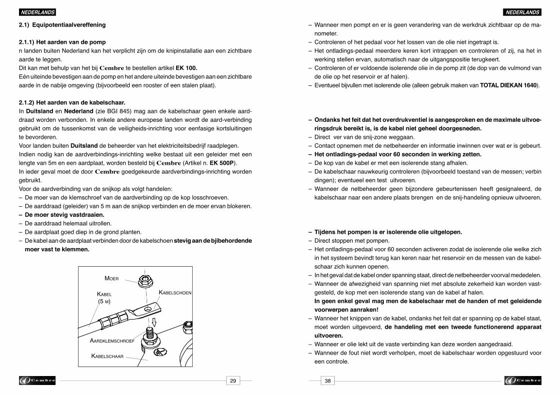
NEDERLANDSNEDERLANDS
2.1) Equipotentiaalvereffening
2.1.1) het aarden van de pompn landen buiten Nederland kan het verplicht zijn om de knipinstallatie aan een zichtbare aarde te leggen.Dit kan met behulp van het bij Cembre te bestellen artikel EK 100.Eén uiteinde bevestigen aan de pomp en het andere uiteinde bevestigen aan een zichtbare aardeindenabijeomgeving(bijvoorbeeldeenroosterofeenstalenplaat).
2.1.2) het aarden van de kabelschaar.In Duitsland en Nederland(zieBGI845)magaandekabelschaargeenenkeleaard-draadwordenverbonden.Inenkeleandereeuropeselandenwordtdeaard-verbindinggebruiktomdetussenkomstvandeveiligheids-inrichtingvooreenfasigekortsluitingente bevorderen.Voor landen buiten Duitsland de beheerder van het elektriciteitsbedrijf raadplegen. Indiennodigkandeaardverbindings-inrichtingwelkebestaatuiteengeleidermeteenlengtevan5meneenaardplaat,wordenbesteldbijCembre (Artikeln.EK 500P).In ieder geval moet de door Cembre goedgekeurdeaardverbindings-inrichtingwordengebruikt. Voor de aardverbinding van de snijkop als volgt handelen:– De moer van de klemschroef van de aardverbinding op de kop losschroeven.–Deaarddraad(geleider)van5maandesnijkopverbindenendemoerervanblokeren.– De moer stevig vastdraaien.– De aarddraad helemaal uitrollen.– De aardplaat goed diep in de grond planten.– De kabel aan de aardplaat verbinden door de kabelschoen stevig aan de bjibehordende moer vast te klemmen.
moer
KabeLsChoen
aardKLemsChroeF
KabeL(5 m)
KabeLsChaar
3829
– Wanneermenpomptenerisgeenveranderingvandewerkdrukzichtbaaropdema- nometer.– Controleren of het pedaal voor het lossen van de olie niet ingetrapt is.–Hetontladings-pedaalmeerderekerenkort intrappenencontrolerenofzij,nahet in werking stellen ervan, automatisch naar de uitgangspositie terugkeert. –Controlerenofervoldoendeisolerendeolieindepompzit(dedopvandevulmondvan de olie op het reservoir er af halen).– Eventueelbijvullenmetisolerendeolie(alleengebruikmakenvan TOTAL DIEKAN 1640).
– Ondanks het feit dat het overdrukventiel is aangesproken en de maximale uitvoe- ringsdruk bereikt is, is de kabel niet geheel doorgesneden.–Directvervandesnij-zoneweggaan.– Contact opnemen met de netbeheerder en informatie inwinnen over wat er is gebeurt.– het ontladings-pedaal voor 60 seconden in werking zetten. – De kop van de kabel er met een isolerende stang afhalen.–Dekabelschaarnauwkeurigcontroleren(bijvoorbeeldtoestandvandemessen;verbin dingen); eventueel een test uitvoeren.– Wanneer de netbeheerder geen bijzondere gebeurtenissen heeft gesignaleerd, de kabelschaarnaareenandereplaatsbrengenendesnij-handelingopnieuwuitvoeren.
– Tijdens het pompen is er isolerende olie uitgelopen. – Direct stoppen met pompen.–Hetontladings-pedaalvoor60secondenactiverenzodatdeisolerendeoliewelkezich inhetsysteembevindtterugkankerennaarhetreservoirendemessenvandekabel- schaar zich kunnen openen.– In het geval dat de kabel onder spanning staat, direct de netbeheerder voorval mededelen.–Wanneerdeafwezigheidvanspanningnietmetabsolutezekerheidkanwordenvast- gesteld, de kop met een isolerende stang van de kabel af halen. In geen enkel geval mag men de kabelschaar met de handen of met geleidende voorwerpen aanraken!– Wanneer het knippen van de kabel, ondanks het feit dat er spanning op de kabel staat, moet worden uitgevoerd, de handeling met een tweede functionerend apparaat uitvoeren.– Wanneer er olie lekt uit de vaste verbinding kan deze worden aangedraaid.– Wanneer de fout niet wordt verholpen, moet de kabelschaar worden opgestuurd voor een controle.
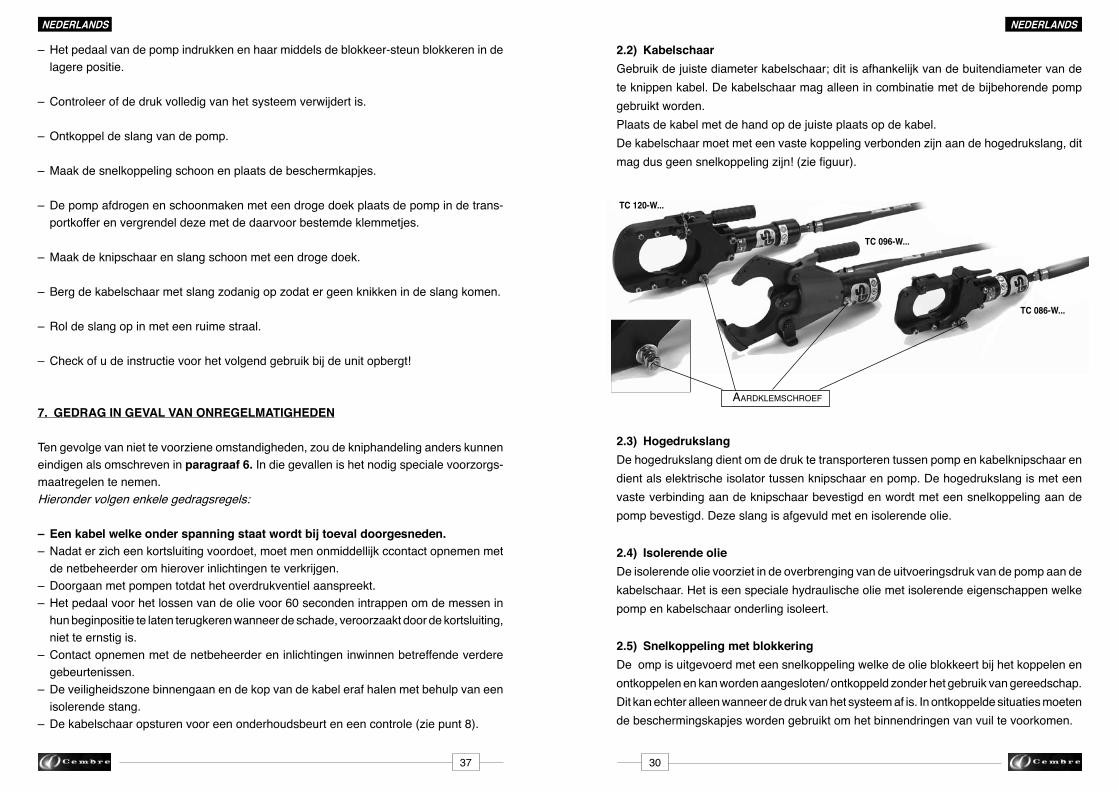
NEDERLANDSNEDERLANDS
2.2) KabelschaarGebruik de juiste diameter kabelschaar; dit is afhankelijk van de buitendiameter van de te knippen kabel. De kabelschaar mag alleen in combinatie met de bijbehorende pomp gebruikt worden.Plaats de kabel met de hand op de juiste plaats op de kabel.De kabelschaar moet met een vaste koppeling verbonden zijn aan de hogedrukslang, dit magdusgeensnelkoppelingzijn!(ziefiguur).
2.3) hogedrukslangDe hogedrukslang dient om de druk te transporteren tussen pomp en kabelknipschaar en dient als elektrische isolator tussen knipschaar en pomp. De hogedrukslang is met een vaste verbinding aan de knipschaar bevestigd en wordt met een snelkoppeling aan de pomp bevestigd. Deze slang is afgevuld met en isolerende olie.
2.4) Isolerende olieDe isolerende olie voorziet in de overbrenging van de uitvoeringsdruk van de pomp aan de kabelschaar. Het is een speciale hydraulische olie met isolerende eigenschappen welke pomp en kabelschaar onderling isoleert.
2.5) Snelkoppeling met blokkeringDe omp is uitgevoerd met een snelkoppeling welke de olie blokkeert bij het koppelen en ontkoppelen en kan worden aangesloten/ ontkoppeld zonder het gebruik van gereedschap. Dit kan echter alleen wanneer de druk van het systeem af is. In ontkoppelde situaties moeten de beschermingskapjes worden gebruikt om het binnendringen van vuil te voorkomen.
3037
–Hetpedaalvandepompindrukkenenhaarmiddelsdeblokkeer-steunblokkereninde lagere positie.
– Controleer of de druk volledig van het systeem verwijdert is.
– Ontkoppel de slang van de pomp.
– Maak de snelkoppeling schoon en plaats de beschermkapjes.
–Depompafdrogenenschoonmakenmeteendrogedoekplaatsdepompindetrans- portkoffer en vergrendel deze met de daarvoor bestemde klemmetjes.
– Maak de knipschaar en slang schoon met een droge doek.
– Berg de kabelschaar met slang zodanig op zodat er geen knikken in de slang komen.
– Rol de slang op in met een ruime straal.
– Check of u de instructie voor het volgend gebruik bij de unit opbergt!
7. GEDRAG IN GEVAL VAN ONREGELMATIGhEDEN
Ten gevolge van niet te voorziene omstandigheden, zou de kniphandeling anders kunnen eindigen als omschreven in paragraaf 6. In die gevallen is het nodig speciale voorzorgs-maatregelen te nemen.Hieronder volgen enkele gedragsregels:
– Een kabel welke onder spanning staat wordt bij toeval doorgesneden.– Nadat er zich een kortsluiting voordoet, moet men onmiddellijk ccontact opnemen met de netbeheerder om hierover inlichtingen te verkrijgen. – Doorgaan met pompen totdat het overdrukventiel aanspreekt.–Hetpedaalvoorhetlossenvandeolievoor60secondenintrappenomdemessenin hun beginpositie te laten terugkeren wanneer de schade, veroorzaakt door de kortsluiting, niet te ernstig is.– Contact opnemen met de netbeheerder en inlichtingen inwinnen betreffende verdere gebeurtenissen. – De veiligheidszone binnengaan en de kop van de kabel eraf halen met behulp van een isolerende stang.–Dekabelschaaropsturenvooreenonderhoudsbeurteneencontrole(ziepunt8).
aardKLemsChroeF
TC 120-W...
TC 096-W...
TC 086-W...

05
06
04
01
02
03
07
08
NEDERLANDSNEDERLANDS
2.6) PompIn de pomp wordt de uitvoeringsdruk opgewekt welke nodig is voor het knippen van de kabel.De pomp wordt bediend door op het pedaal te trappen.
Bild 2 - Onderdelen Pomp
01 - Frame van de pomp 05 -Terugkeer-veervoorhetpedaal02 - Pedaal voor het verwijderen van de druk 06 - Manometer 03 - Voetpedaal 07 - Aardklem04 - Blokkering van het pedaal 08 - Snelkoppeling
Het pedaal voor het verwijderen van de oliedruk zorgt ervoor dat de olie kan terugke-ren in het olie reservoir van de pomp zodat de messen van de knipschaar weer volledig kunnen terugkeren naar hun beginstand.
De manometer geeft dewerkdruk aan welke in het systeem aanwezig is.Het drukveld met rode achtergrond geeft de limiet aan van de maximaal toegestane werkdruk, welke niet mag worden overschreden.Bij het bereiken van de maximaal toegestanewerkdruk, belet het overdrukventiel binnen in de pomp een verdere verhoging van de druk.
Het klemmetje voor de equipotentiale verbinding op het frame van de pomp maakt de verbinding van een aarddraad mogelijk. Om het gevaar van potentiaalverschillen te voorkomen,moetdepompwordenverbondenmeteenaardpotentiaal(rooster,dunnestalen plaat enz.).
3631
– De hogedrukslang helemaal uitrollen.
– De pomp op de maximaal mogelijke afstand vanaf het te knippen punt plaatsen en deze aan de slang koppelen.
– Deplaatswaardepompgezetwordtmoetzodaniggekozenwordendatdehoge- drukslang“zigzag”ophetterreingelegdkanworden.Dezemaatregelwordtge- nomen omdat tijdens het knippen de slang ietsjes korter wordt.
–Wanneerdooromgevings-motievendeminimaleafstandvan10mvanafdeplaatsvan het snijden niet kan worden gerespecteerd, zullen er andere voorzorgsmaatregelen nodigzijn(bijvoorbeeldaardophogingenofbeschermendewanden)omdebedienings- man van de kabelschaar te beschermen voor een mogelijke vlamboog veroorzaakt door een kortsluiting.
– Telkenswanneerhetgevaarvoorspanningsverschillenbestaat(vanhetsnijpunttotde pompi),kandepompaandeaardewordenverbondendoormiddelvanhetaardklem- metjeendespecifiekegeleider zodanigdatereenequipotentiale verbindingwordt gerealiseerd.
– Contact opnemen met de netbeheerder.
– Controleren dat er niemand in de gevarenzone aanwezig is.
– De handeling van het knippen uitvoeren door op het pedaal te trappen, Plaats uw voet inhetmiddenvandebeugel.Controleertijdenshetpompendewerkdrukdoordema- nometer te observeren.
– Gedurende het knippen kunnen er variaties inde druk ontstaan, dit is afhankelijk van het type kabel.
– Het in noodzakelijk om door te pompen totdat het overdrukventiel met een hoorbare klik aangeeft dat de knipbeweging voltooid is!
–Hiernakuntumethetreleasepedaal(02)deknipschaaropenen(ditzalongeveer60 sec kunnen duren).
– Neem contact op met de netbeheerder en indien er geen bijzondere gebeurtenissen gemeld worden kan men de beveiligde zone binnentreden
– U kunt nu de knipschaar aan de handgreep beetpakken en deze verwijderen van de kabel.
☞
☞
☞

2.7) Opschriften en hun betekenisKabelschaar,hogedrukslangenpompmoetenvoorzienzijnvanopschriftenwelkeeenduidelijkeidentificatiemogelijkmaken,alsmededewerkingvandeafzonderlijkeonder-delen van de kabelschaar.
Het merkteken 60000 V betekent dat het apparaat geschikt is voor het gebruik op komponenten tot 60 kV.
Toegestanewerkdruk:625barDemaximalewerkdrukvanhetsysteemis625bar
Op de kabelknipschaarMaximaaltoegestanediametervandekabel:85mm,95mm,120mm(volgenshettype;zie technische gegevens).De kabels met een uitwendige diameter tot aan de aangegeven waarde kunnen gewoon worden gesneden.
Op de hogedrukslangAanduidingendieiedere50cmherhaaldwordenopdehd-slang:
Aan beide uiteinden van de hogedruk slang:
– (merktekenvandeproducentvanheadersvandehogedrukslang)
– 10 / 30465 (jaarvandeproduktie/laboratoriumtestaantal)
– Q.C. AVR.10 (kwaliteitscontrole;vervaardigd datum maand. jaar)
– 630 bar (toegestanewerkdruk)
– 60 kV(apparaatgeschiktvoortoepassingentot60kV)
☞
NEDERLANDSNEDERLANDS
3235
4. TRANSPORT
De kabelschaar is met maximale zorgvuldigheid geproduceerd en wordt geleverd in een stevige doos voor het transport. De transportkoffer beschermd de losse komponenten tegen beschadiging gedurende de opslag en gedurende het transport tot aan de werkplaats.Dekabelschaar mag alleen op de plaats waar hij gebruikt gaat worden uit de transportkof-fer worden gehaald.
5. INLEIDENDE FASEN
De kabelschaar moet worden gebruikt zoals in deze instructies voor het gebruik wordt beschreven.DenormDINVDE0105-100moetwordennageleefd.
– De kabelschaar uit de doos voor het transport halen op de plaats waar hij gebruikt gaat worden. – Alle komponenten (snijkop, hogedrukslangenpomp)moeten vòòr het gebruik ervan worden gecontrolleerd op duidelijke beschadigingen.
✶ Snijvlakken van de messen beschadigd? ✶ Hogedrukslang buis schoon en zonder zichtbare beschadigingen? ✶ Snelkoppelingen schoon? ✶ Functioneert de manometer? ✶ Is het pedaal van de pomp gemakkelijk te bedienen? ✶LaststarZorgthetretourpedaalvoordeterugkeervandeolie?
– In een straal van 10 m om de werkplaats heen moet een beschermde zone worden gecreeerd zodanig dat de toegang aan wie dan ook in deze zone wordt belet.
6. DE KNIP-PROCEDURE
Volg de knip procedure is zoals die wordt voorgeschreven door de locale netwerk beheerder!(bijv.BGI845ZH1/437).Dit zou kunnen zijn:
– Neem contact op met de beheerder van het net.
– Transporteer de kabelknipschaar aan de handgreep naar de te knippen kabel.
– De messen van de knipschaar om de te knippen kabel heen plaatsen en de positie stabiliseren(bijvoorbeelddoordeknipschaarstevigopdegrondtedrukkenofbijde TC096-WZ-1000-KVhetsteunvoetjetedraaien). Inhetgevaldaterdriepoligekabelsgekniptmoetenworden,moetende3fasengelijk- tijdig in de knipschaar geplaatst worden.
☞
producent van de hogedruk slang
type van de hogedruk slang
nominale diameter
Max. werkdruk
PSI en BAR
kwartaal en jaar produktie Seriennr.
EATON SYNFLEX® 3VE0-03 3/16" I.D. W.P. 10000 P.S.I. (690 BAR) (4Q09) NON CONDUCTIVE 144388
niet geleidend

85
PO6000-WZ-KVBenutzenmit Pumpe
Serien-Nr.
TC086-WZ-1000-KVTypKabel. Ø Max. mm
Jahr
625 bar
Made in Italy
60000 V
Zugelassener Höchstdruck
95
PO6000-WZ-KVBenutzenmit Pumpe
Serien-Nr.
TC096-WZ-1000-KVTypKabel. Ø Max. mm
Jahr
625 bar
Made in Italy
60000 V
Zugelassener Höchstdruck
120
PO6000-WZ-KVBenutzenmit Pumpe
Serien-Nr.
TC120-WZ-1000-KVTypKabel. Ø Max. mm
Jahr
625 bar
Made in Italy
60000 V
Zugelassener Höchstdruck
PO6000-WZ-KVDOPPELKOLBENHYDRAULIK FUSSPUMPE TYP
625 bar
Serien-Nr. Jahr
ZugelassenerHöchstdruck
TC086-WZ-1000-KV TC096-WZ-1000-KV TC120-WZ-1000-KV
ErlaubteSchneidköpfe
Made in Italy
60000 V
NEDERLANDSNEDERLANDS
3433
3. TEChNISChE GEGEVENS
Pomp:
Type Fabrikant
Max. toege-stane druk
(bar)
Inhoud reservoir
(cm3)
Gewicht(kg)
Lengte
(mm)
Breedte
(mm)
Hoogte
(mm)
Cembre 625 1000 9,7 680 200 163
hogedrukslang:
Type Fabrikant SlangNominale diameter(inch)
Totale lengte (m)
630 >10
Toegestane druk (bar)
Isolerende olie:
Kabelscharen:
Type
TC086-WZ-1000-KV
FabrikantMax. toege-stane-druk
(bar)
Gewicht
(kg)
Maxkabel-diam.(mm)
Lengte
(mm)
Breed-te
(mm)
Volumeolie
(cm3)
TC096-WZ-1000-KVTC120-WZ-1000-KV
CembreCembreCembre
625625625
89,57123,8181,5
6,99,310,5
8595120
369,5394,0481,5
135242175
Metalen koffer:
Type Gewicht(kg)
Afmetingen(mm)LxBxH
VALCP096-W 12,6 786x430x175
PO6000-WZ-KV
In het geval dat de olie per ongeluk naar buiten loopt, deze met zand of aarde opnemen. Hetverontreinigdezandofdeverontreinigdeaardemoetenviadeplaatselijkvastgesteldeafvaver-werkings-systemenwordenverwijderd.
TypDichtheid15°C(kg/m3)
DIEKAN1640 853
Fabrikant
TOTAL
Vriespunt
(°C)
-33
Vlampunt
(°C)
174 12,8
Viscositeit40°C
(mm2/S)
TypeSerienummer
Maximaal toegestane druk
JaarMax kabel diameter
Toegestane kabelscharen
Serienummer
2-TRAPSHYDRAULISCHE VOETPOMP
TypeSerienummer
Maximaal toegestane druk
Jaar
Max kabel diameter
TypeSerienummer
Maximaal toegestane druk
JaarMax kabel diameter
Jaar
VERMELDE GEGEVENS OP hET METAALETIKET:
Te bedienen met voetpomp
Max. toegestane druk
Te bedienen met voetpomp
Te bedienen met voetpomp
SYNFLEX EATON 3VE0-03 3/16