Embed Size (px)
Citation preview

CABLE PROTECTCABLE CARRIERS (DRAG CHAINS, ENERGY CHAINS, CABLE CONDUITS, CABLE TRACKS)

CONTACT USWORLD HEADQUARTERS
9900 North Alpine RoadMachesney Park, IL 61115+1 815-636-9900+1 888-436-6446 (toll free)+1 815-636-1988 (fax)[email protected]
EUROPEAN HEADQUARTERS
Hennig GmbHÜberrheinerstr. 585551 Kirchheim, Germany+49 89 96096-0+49 89 96096-120 (fax)[email protected]
See pages 27-28 for a complete list of our worldwide locations / contact info
Throughout the Industrial world Hennig provides the protection manufacturers need so they can produce at a higher level in a safe, clean and productive environment. Wherever chips are made, there’s likely a Hennig product keeping them from becoming a problem.
We know that the road to success of our customers passes through the quality of our work, quick responsiveness and the value we offer. This is why a new mission statement “Making Our Customers Successful” is our company’s roadmap to what we want to be and how to get there. Having won our customers’ confidence and contributing to their success is not only our final goal, it is a powerful stimulation to improvement and growth. For this reason, we measure our success through our customers’.
1
Making our customers successful.

w w w . h e n n i g w o r l d w i d e . c o m
3-10
11-18
DESIGN GUIDELINES & ARRANGEMENTS
KOLIBRI SYSTEMS
TABLE OF CONTENTS
2
19-30 PKK SYSTEMS
31-44 SLE STEEL CHAIN SYSTEMS
45-48 STABIFLEX SYSTEMS
49-50 WORLDWIDE CONTACT INFO

3
CABLE CARRIERS | DESIGN GUIDELINES
SELECTION OF THE ENERGY CHAIN AND MATERIALFor most applications energy chains made of plastic is your first choice. Chemical resistance, light weight and low costs are the major advan-tages. Steel chains are used under extreme payloads and high mechan-ical or other particular requirements. For extreme cycles the hardened (carburized) steel is required to achieve long life.
CALCULATION OF CROSS-SECTIONFirst, the cross-section required for the wires is determined, and then specific motions or arrangements, aggressive environmental conditions or other factors lead to your selection. A pre-selection of the product series may use the fields of application (see product series chapter).All lines must be able to move freely in the energy chain. This requires an individual clearance to be taken into account for each line: round cable: 10% of the diameter flat cable: 10% of the cable width and height hoses: 20% of hose diameter
Optimum requirement is the separation of all lines by means of individ-ual chambers. Especially with varying diameters or multi-layer wiring a separation by vertical and horizontal dividers is required.If several lines are to be laid in one chamber, the chamber dimensions have to be restricted so that they maintain their relative positions. Even multi-layer arrangements of flat cables have always to be separated with horizontal dividers.When using pressure hose a change in length has to be taken into ac-count through additional clearance in the chain bow (radius), which can be achieved by a corresponding chain height (a).The distribution of the energy chain cross-section should be symmet-rical in order to ensure an uniform load. In addition heavy lines are laid out close to the links to minimize the bending loads on the transverse bars.
DETERMINATION OF THE BENDING RADIUSThe bending radius of the energy chain is determined by the minimum permissible bending radius of the cables and hoses, the available installation space and the polygon oscillation PA of the energy chain. In general, a minimum bend radius of 10d is considered, where d is the largest existing line diameter. Cables with smaller minimum bend radii are available by some manufacturers.The polygon oscillation PA influences the moving of an energy chain. A large bend radius at the same pitch results usually in a calmer move-ment of the energy chain. The installation space must have a height of more than 2R + c, where R is the set-radius and c is the link height of the energy chain. The real radius is the set radius +0/-5%. The preten-sion of the energy chain should also be considered.

4w w w . h e n n i g w o r l d w i d e . c o m
CABLE CARRIERS | DESIGN GUIDELINES
CABLE CARRIER LENGTHIn standard applications the fixed connector of the energy chain is arranged in the middle of the travel distance. The moving connector moves horizontally over the fixed connector between the end positions of the travel. The required length of the energy chain between the first and the last pivoting link is then determined as follows:
L = LV/2 + 4 R
L length of the energy chain LV length of travel R bending radius of the energy chain
If the fixed connector is not in the middle of the travel, the energy chain has to be extended by a displacement of x:
L = LV/2 + 4 R + x
x offset of the fixed connector
After the selection of the energy chain, the length is rounded up to the link pitch. This length is the ordering length of the energy chain.The connectors height is double bend radius plus link height:
HA = 2 R + c
HA connector height c link height of the energy chain
REVIEW OF THE FREE CARRYING LENGTHThe additional load is the weight of all cables and hoses, divided by the length of the chain:
ms = mL/L
mL cable weight mS specific additional load
Thus with calculated additional load and the help of the load diagram the free carrying length of the energy chain can be verified.
If the additional load is too high for a particular chain an energy chain with greater free carrying length is chosen or constructive changings have to be done that allow the operation with the chosen energy chain (eg, gliding arrangement, support rollers, SYSTEM MARATHON orsimilar).

5
CABLE CARRIERS | DESIGN GUIDELINES
PRETENSION AND PERMISSIBLE SAGEnergy chains are supplied with pretension. Exceptions are energy chains for vertical or sliding arrangements as well as on the side lying energy chains, for example, in a circular arrangement.
The pretension is a manufacturing tool to achieve energy chains with in-creased free carrying lengths. The values for the pretension is set by the manufacturer. Our energy chains made of steel are manufactured with 5 mm / m and plastic energy chains up to 25 mm / m as pretensionwith no load.
The sag is due to the additional load and the weight of the energy chain. Due to the significantly lower elongation of steel (0.2% linear elongation) compared to plastics the permissible sag of the steel chains is limited lower than for plastic energy chains.On the other hand, the effect on plastic energy chains of a long-term static load with a long unsupported length of the upper strand chains will increase the sag (creeping of plastics). Elevated temperatures and humidity increases this effect. The sag of energy chains is also in-creased by use-wear.
The maximum allowable sag can only be judged in the assessment of all operating conditions. Within the limits for the free carrying length specified in the load diagram the sag is within the permissible range at normal operating and environmental conditions.
In addition the following factors have to be taken into account:Using toughs and slow moving energy chain sag is limited.
For high accelerations and high travel speeds too much sag is a prob-lem. A defined force application at the moved connector is not guaran-teed and uncontrollable chain oscillations can occur. Thus the energy chain material is subjected to extreme dynamic stresses. In such cases, corrective steps should be taken.
The first step is the selection of an energy chain with increased free carrying length. If this can not be done, see page 6 for alternatives.

6w w w . h e n n i g w o r l d w i d e . c o m
CABLE CARRIERS | DESIGN GUIDELINES
SUPPORT ROLLS AND SUPPORT RAILSSupport rollers can increase the maximum travel LV of steel chains by up to four times the free carrying length Lf. With additional support rollers and a support rail the maxi-mum range of movement can be expanded up to eight times the free carrying length.The use of support rollers with support frames, is limited to speeds below 1 m / s.
RAISED TROUGHThis type is mainly used with plastic energy chain applications. As with the use of support rolls the maximum travel can be increased up to four times the free carrying length. Because of the larger permissible sagging, support rolls are not suitable for plastic energy chains.
SUPPORT CARRIAGEFor long travel distances and high additional loads support carriages can be used with reverse traveling energy chains. The side-mounted support rolls carry the energy chain and move the support carriage. The energy chains now only face pull forces and through this an extremely long life is achieved even at high additional loads.
SYSTEM MARATHONThe patented SYSTEM MARATHON for unlimited travel is also designed for high speeds and high accelerations. The upper run is running with supporting rollers over the entiretravel on continuous flat rails and the rollers swing in the radius to lay down the energy chain at the bottom profile. In the back movement the rollers swing out again and lead the energy chain without wear over the entire travel. The SYSTEM MARATHON is not dependent upon the type of energy chain and therefore steel energy chains are asequally suitable as plastic energy chains.
GLIDING ENERGY CHAINSGliding energy chains require guiding the upper run in a continuous trough. In addition, the first half of travel slide bars are mounted or the energy chain is extended via thefixed end in the middle of the travel out up to the starting point to create a continuous gliding plane (see also chapter troughs).
With high dynamic demands on the energy chain, lowering the moving connection end may be necessary to result in a better introduction of push forces into the energy chain.In travels over 30 m, velocities above 1.5 m / s and acceleration of 1 m/s2 lowering the moving end is recommended and requires an additional length of the energy chain. Chain links with a opposite bend radius minimize the required additional length and minimize oscillations of the remaining free carrying length of the energy chain.
PKK, PLE and SLE energy chains for gliding arrangements are preferably equipped with sliders that can be replaced after reaching the wear limit without dismantling or replacing the energy chain.

7
CABLE CARRIERS | ARRANGEMENTS
NORMAL ARRANGEMENT (N)In the normal arrangement the fixed connector is usually on the first link in the lower strand in the middle of the travel. The moving end connec-tor is moving the chain in a straight line lengthwise at a height of 2R+c over the entire travel. The upper strand is steadily reduced through the bending of the individual links until the whole chain length is taken to the bottom or in a trough.
This arrangement allows maximum speeds and extreme acceleration with optimum durability.
MULTIAXIAL (M)In the multiaxial arrangement is a vertical and horizontal motion of the driver along the x-axis (travel direction) and one or more movement in the y- or z-direction. While running in the y-direction may be done by any conventional energy chain, the movements in the z-direction require the energy chain system ALLROUND.
FREE OVERHANG (F)In contrast to the normal arrangement the freely exceeding lower strand is supported only partially by a substructure. Due to the high weight load on the lower strand in this arrangement only significantly reduced travel distance is possible.
MOVED END DOWNSIDE (U)If the driver is positioned in the lower, due to the heavy weight only a reduced travel distance is possible (see above).

8w w w . h e n n i g w o r l d w i d e . c o m
CABLE CARRIERS | ARRANGEMENTS
NESTED TRAVEL (I)The arrangement of two or more energy chains with different bending radii or even different energy chains makes sense when using a variety of cables and hoses together. The energy chains are moved together by a common driver.
GLIDING ARRANGEMENT (L)If the free carrying length is exceeded, the energy chain changes into agliding state. In this arrangement, use energy chains without pretension.A trough is required (see chapter troughs). Sliders increase the lifespanand can be replaced if necessary.
VERTICAL TRAVEL (S)Vertical travel arrangements are often installed in systems in which multiple linear axes are coupled. In this arrangement usually energy chains without pretension are used. Vertical arrangement with multiaxial movement needschains with pretension. The weight of the lines and of the energy chain has to be placed and pushed by the straight part of the chain. This forces should be caught by a supporting. The energy chain should be arranged so that optional cross accelerations are in the y-direction
VERTICALLY HANGING (H)Elevators, high-bay stores and doors are typical applications for energy chains in vertically hanging arrangement. In this arrangement the energy chain is predominantly tensile stressed. Lateral acceleration should be layed if any, in the y-direction. Energy chains are without pretension.
HANGING MULTIAXIAL (HM)The energy chain ALLROUND provides the combination of linear and rotary motion.

9
CABLE CARRIERS | ARRANGEMENTS
HORIZONTAL (W)(on the side)Energy chains are arranged horizontally lying on their side, for example, if the space does not allow a normal arrangement. In some cases, lying on its side provides an alternative for very long traverse at low speeds and strokes. In this application mainly chains without pretension areused. In general, suitable guide troughs and gliding discs or rollers are required.
DRIVING APART (A)With energy chains moving apart the calculation of the energy chain length does not follow the usual pattern, but be adapted to theindividual requirements of the application.
CIRCLE (K)(on the side)The circular motion is a special form of chain movement. For circle movement a part of the energy chain has to be manufactured with an opposite bending radius R2. The outer radius R3 is derived from the link height, the bending radius of the energy chain R1 and the oppositeradius R2.
This type of horizontal arrangement allows rotation up to 520 °.A customized guide channel is required.

10w w w . h e n n i g w o r l d w i d e . c o m
CABLE CARRIERS | WIRING
Energy chains are arranged horizontally lying on their side, for example, For layingin energy chains only highly flexible cables with permissible bending radii and suffi-cient dynamic capacity suitable. The cables have to be laid twist free to move freely lengthwise. Cable on a reel should be unrolled in the reverse winding direction and placed in the extended state in the energy chain. For intermediate storage the lines are ideally laid out straight. The material relaxation occurs in this case facilitates a twist-free installation.
The distribution of the chain interior must prevent mutual interference between the wires with dividers or wrap clamping of different diameters safely, so that each line can move freely in the longitudinal direction (see design guidelines). In particular in the energy chain radius tensile stressed wires increase wear drastically and reduce the reliability. A fixation of the wires or a bundle of several lines using cable ties or the like within the energy chain can also cause damage.
STRAIN RELIEFWith long travel distances and high speeds the cables should be attached with strain relief only at the driver end. For free carrying energy chains recommend for aestheticreasons, a strain relief on both ends. The distance of strain relief to the bending stressed area depends on the particulars of the line manufacturer. Hydraulic hoses have special needs.
INTEGRATED STRAIN RELIEFIn this space-saving type the strain relief is directly attached to the plastic dividers (PZ) in the first link of the energy chain (note the mounting direction of PZ!). In order to avoid premature line wear caused by dynamic loads, a small excess length of the chain is recommended .
COMBINED STRAIN RELIEFThe combined strain relief combines the advantage of a sufficient distance from the bending line areas to the strain relief by the simple and space-saving installation of the integrated strain relief. The anchor profile is provided to the drilling dimensions of the energy chain and attached to the chain. The lateral insertion and extraction of strain relief elements is through the C-profile.
SEPARATE STRAIN RELIEFThe separate strain relief is recommended for high dynamic loads and large line diameters. A sufficient distance of the strain relief to the moved line areas and length compensations are easy to implement. In this variant the lateral insertion andextraction of the strain relief elements with no installation work on the cable carrieris possible.

11
KOLIBRI PLASTIC CABLE CARRIERS
KOLIBRI FEATURES• Inexpensive energy chain for light-weight applications.
• Robust design
• Easy access by flap stays. Extremely rigid and wear resistant.
• The patented opening offers high rigid torsion behavior and comfortable handling in one.
• Unique separation with the pinch stays smallest dimensions.
• Mounting brackets not needed. All plastic energy chains are equipped with integrated mounting holes
• Smooth motion. No “break in time” needed
APPLICATIONSrobotics
handling
transportation
paper production
textile industries
water plants

12w w w . h e n n i g w o r l d w i d e . c o m
TRAVEL DISTANCEThe maximum travel distance is given by the arrangementand the load (weight of the lines). At normal arrangementsthe maximum travel distance is double the free carryinglength. Support rollers or similar equipment may exceed thisvalue.In gliding arrangements travel distances up to 100 m arepossible (according to the application).For longer travels see chapter on design guidelines.
TRAVEL SPEEDThere are no limits for the travel speed in general. But withgliding arrangements application specific influences have tobe taken into account.
ACCELERATIONThere are no limits for the accelerations, in general. Limitsmay occur through the tensile stresses at high line weights.
DIMENSIONSbending radii: 15 - 400 mminner height: 7 - 50 mminner width: 7 - 195 mmweight: 0.06 - 2.7 kg/m
TEMPERATURELong term temperature limits are between -20°C and 100°C.
SPECIAL VARIANTSELTOLA: silent runningATEX: EX-protectionESD: antistaticV-0: self extinguishing
Kolibri 65.xxx
Kolibri 50.xxx
Kolibri 40.xxx
Kolibri 30.xxx
Kolibri 22.xxx
Kolibri 15.xxx
Kolibri 10.xxx
free carrying length Lf / (m)
load
/ (k
g/m
)
5
4
3
2
1
00 1 2 3
Lf
LOAD DIAGRAM
KOLIBRI PLASTIC CABLE CARRIERS

13
KOLIBRI PLASTIC CABLE CARRIERS | TYPES
c a
d
b
pitch
radius
Kolibri 00.000.0 standard type flap open bars in inner radius separable with pinch stayintegrated connector
Kolibri 00.000.1 openable in outer radius flap open bars in outer radiusseparable with pinch stayintegrated connector
Kolibri 00.000.2 rigid version flap open bars in inner radius separable with PZ integrated connector
Kolibri 00.000.3 one part chain linksnot openable not separableintegrated connector
Kolibri 00.000.5 closed type flap open covers in outerradius separable with pinchstay integrated connector
Kolibri 00.000.6 equal .2 flap open bars inouter radius
Kolibri 00.000.7 telescopic type PKK stays in inner radiusseparable via Pz separateconnectors
Kolibri 00.000.4 film stay film stay in inner radiusnot separable (integrated connector)
14w w w . h e n n i g w o r l d w i d e . c o m
Kolibri
type
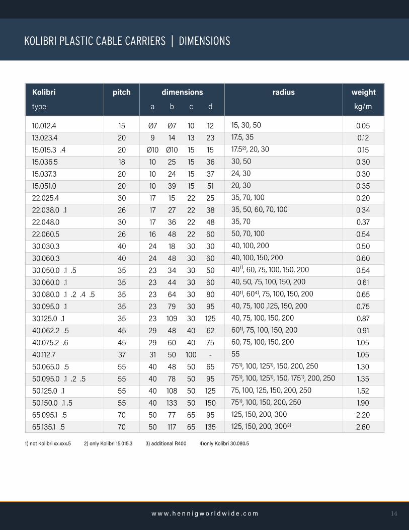
10.012.413.023.415.015.3 .415.036.515.037.315.051.022.025.422.038.0 .122.048.022.060.530.030.330.060.330.050.0 .1 .530.060.0 .130.080.0 .1 .2 .4 .530.095.0 .130.125.0 .140.062.2 .540.075.2 .640.112.750.065.0 .550.095.0 .1 .2 .550.125.0 .150.150.0 .1 .565.095.1 .565.135.1 .5
dimensions
a
Ø79
Ø101010101717171624242323232323292931404040405050
b
Ø714
Ø1025243915273648184834446479109486050487810813377117
c
10131515151522222222303030303030304040100505050506565
d
122315363751253848603060506080951256275-
659512515095135
weight
kg/m
0.050.120.150.300.300.350.200.340.370.540.500.600.540.610.650.750.870.911.051.051.301.351.521.902.202.60
radius
15, 30, 5017.5, 3517.52), 20, 3030, 5024, 3020, 3035, 70, 10035, 50, 60, 70, 10035, 7050, 70, 10040, 100, 20040, 100, 150, 20040¹⁾, 60, 75, 100, 150, 20040, 50, 75, 100, 150, 200401), 604), 75, 100, 150, 20040, 75, 100 ,125, 150, 20040, 75, 100, 150, 200601), 75, 100, 150, 20060, 75, 100, 150, 20055751), 100, 1251), 150, 200, 250751), 100, 1251), 150, 1751), 200, 25075, 100, 125, 150, 200, 250751), 100, 150, 200, 250125, 150, 200, 300125, 150, 200, 3003)
pitch
1520201820203026302640403535353535454537555555557070
1) not Kolibri xx.xxx.5 2) only Kolibri 15.015.3 3) additional R400 4)only Kolibri 30.080.5
KOLIBRI PLASTIC CABLE CARRIERS | DIMENSIONS

15
KOLIBRI PLASTIC CABLE CARRIERS | SIZES
height 10
height 13
height 15
height 22
height 30
height 40
height 50
height 60

16w w w . h e n n i g w o r l d w i d e . c o m
link (open type) link (closed type) flange pivot flange drilling horn stay connector horn stay 65 HS65 horn stay 85 HS 85damping element PZ (divider) PZ (pinch stay) flap stay flap cover notched horizontal dividernotched horiz. divider flyingtelescopic horizontal dividertelescopic horiz. divider flyingladderstay connector 10.012.4 holeconnector 10.012.4 pivot
12345678910111213141516171819
❹
❶
⓫
⓬❸
⓲
⓳
❻
❼
❺
❿
⓭ ⓮
❾
❶
⓯ ⓱ ⓰
❷
❽
Kolibri with Snap
KOLIBRI PLASTIC CABLE CARRIERS | PARTS
17
KOLIBRI PLASTIC CABLE CARRIERS | ASSEMBLY
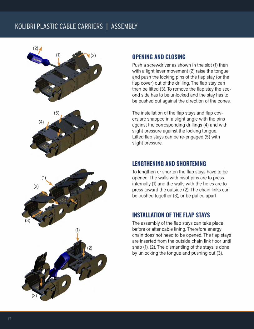
OPENING AND CLOSINGPush a screwdriver as shown in the slot (1) then with a light lever movement (2) raise the tongue and push the locking pins of the flap stay (or the flap cover) out of the drilling. The flap stay can then be lifted (3). To remove the flap stay the sec-ond side has to be unlocked and the stay has to be pushed out against the direction of the cones.
The installation of the flap stays and flap cov-ers are snapped in a slight angle with the pins against the corresponding drillings (4) and with slight pressure against the locking tongue.Lifted flap stays can be re-engaged (5) with slight pressure.
LENGTHENING AND SHORTENINGTo lengthen or shorten the flap stays have to be opened. The walls with pivot pins are to press internally (1) and the walls with the holes are to press toward the outside (2). The chain links can be pushed together (3), or be pulled apart.
INSTALLATION OF THE FLAP STAYSThe assembly of the flap stays can take placebefore or after cable lining. Therefore energy chain does not need to be opened. The flap stays are inserted from the outside chain link floor until snap (1), (2). The dismantling of the stays is done by unlocking the tongue and pushing out (3).
(1)(2)
(3)
(4)
(5)
(1)
(2)
(3)
(1)
(2)
(3)
18w w w . h e n n i g w o r l d w i d e . c o m
KOLIBRI PLASTIC CABLE CARRIERS | ASSEMBLY
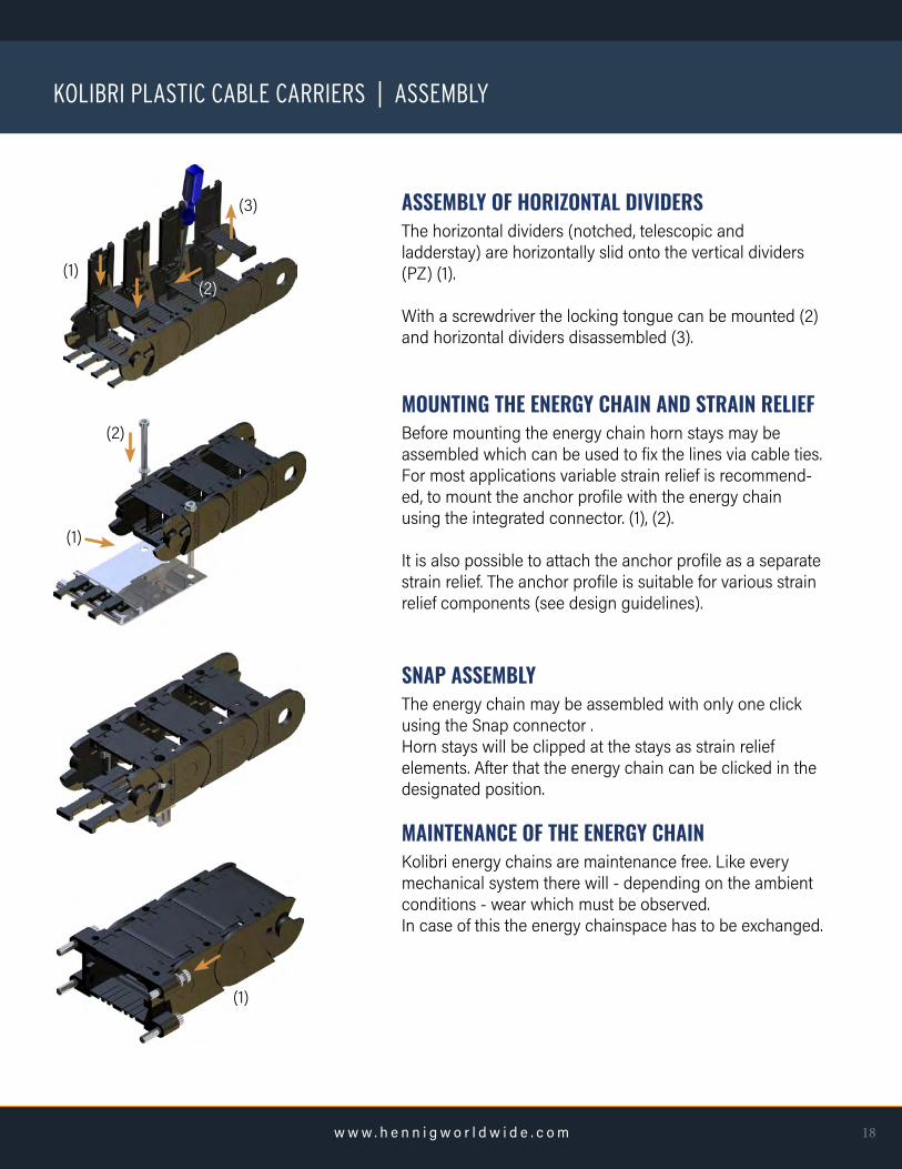
ASSEMBLY OF HORIZONTAL DIVIDERSThe horizontal dividers (notched, telescopic andladderstay) are horizontally slid onto the vertical dividers (PZ) (1).
With a screwdriver the locking tongue can be mounted (2) and horizontal dividers disassembled (3).
MOUNTING THE ENERGY CHAIN AND STRAIN RELIEFBefore mounting the energy chain horn stays may beassembled which can be used to fix the lines via cable ties.For most applications variable strain relief is recommend-ed, to mount the anchor profile with the energy chain using the integrated connector. (1), (2).
It is also possible to attach the anchor profile as a separatestrain relief. The anchor profile is suitable for various strainrelief components (see design guidelines).
SNAP ASSEMBLYThe energy chain may be assembled with only one clickusing the Snap connector .Horn stays will be clipped at the stays as strain reliefelements. After that the energy chain can be clicked in thedesignated position.
MAINTENANCE OF THE ENERGY CHAINKolibri energy chains are maintenance free. Like everymechanical system there will - depending on the ambientconditions - wear which must be observed.In case of this the energy chainspace has to be exchanged.
(1)(2)
(3)
(2)
(1)
(1)

19
PKK PLASTIC CABLE CARRIERS
PKK FEATURES• Mounting brackets not needed. All plastic energy chains are equipped with integrated mounting holes on each link
• Robust design
• Fast Stay assembly and disassembly.
• Extremely rigid and wear resistant.
• Easy to shorten and lengthen
• Three-dimensional chain
• Smooth motion. No “break in time” needed
APPLICATIONSrobotics
handling
machine tools
textile industries

20w w w . h e n n i g w o r l d w i d e . c o m
TRAVEL DISTANCEThe maximum range of travel is determined by thearrangement and the additional weight (line weight). Atnormal arrangement the maximum travel is double freecarrying length. Support rollers or similar constructive stepscan increase this value.Travel distances up to 100 meters are possible (seechapter on design guidelines).
TRAVEL SPEEDThere are no limits for the travel speed in general. But withgliding arrangements application specific influences have tobe taken into account.
ACCELERATIONThere are no limits for the accelerations, in general. Limitsmay occur through the tensile stresses at high line weights.
DIMENSIONSbending radii: 40 - 500 mminner height: 16 - 80 mminner width: 30 - 400 mmweight: 0.6 - 3.4 kg/m
TEMPERATURELong term temperature limits are between -20°C and 100°C.
SPECIAL VARIANTSELTOLA: silent runningALLROUND all movementsATEX: EX-protectionESD: antistaticV-0: self extinguishing
free carrying length Lf / (m)
load
/ (k
g/m
)
10
8
6
4
2
00 2 4 6
Lf
LOAD DIAGRAM
PKK 520
PKK 340
PKK 320
PKK 240
PKK 220
PKK 140
PKK 120
PKK PLASTIC CABLE CARRIERS

pitch
R (radius)
21
PKK PLASTIC CABLE CARRIERS | DIMENSIONS
c a
d (b + 2f)
b (stay length) f
PKK
type
120, 121, 123, 125110, 111, 113, 115140, 141, 143220, 221, 223, 225, 228210, 211, 213, 215240, 241, 243, 245320, 321, 323, 325, 328310, 311, 313, 315340, 341, 343, 345520, 521, 523, 525, 528510, 511, 513, 515
dimensions
a
1616303434445151618080
c
252540505060757585104104
weight
kg/m
.60
.601.031.501.401.702.502.502.703.403.20
pitch
353554656565909090115115
DIMENSIONS
f
11891510101812151414
1) The usable interior width is stay length - 2e minus the width of the used PZ2) First latching the PZ (latching all 2mm); PKK 215,225,245, 315, 325, 345 i=22;3) Dimension does not apply to the closed type4) PKK 115 and 125 from R50, 215 and 225 from R100, 245, 315 and 325 from R150, 345, 525 and 515 from R2005) The inner radius covers (ASI) of length 200 mm of the PKK 215, 225, 245 and 300 mm and 200 mm of the PKK 315, 325, 345 are designed with a pivot on one side.6) PKK 228 from R100, PKK 328 from R150, PKK 528 from R200 * Additional stays available+ Sliders available

22w w w . h e n n i g w o r l d w i d e . c o m
PKK
type
120, 121, 123, 1254)110, 111, 113, 1154)140, 141, 143220, 221, 223, 2254), 2286)210, 211, 213, 2154)240, 241, 243, 2454)320, 321, 323, 3254), 3286)310, 311, 313, 3154)340, 341, 343, 3454)520, 521, 523, 5254), 5286)510, 511, 513, 5154)
R (radius)
radii available for each type
40, 50, 60, 7540, 50, 60, 7550, 60, 80, 100, 150, 20075, 100, 150, 200, 250, 30065, 75, 100, 100, 125, 150, 200, 250, 30075, 100, 120, 150, 200, 250, 300100, 150, 200, 250, 300, 400100, 130, 150, 200, 250, 300, 400100, 150, 200, 250, 300, 400150, 200, 250, 300, 400, 500150, 200, 250, 300, 400, 500
RADIUS
PKK
type
120, 110, 111, 113*, 121, 123*115, 125140, 141, 143*220, 210, 211, 213*, 221, 223*, 228+
215, 2255)+
240, 241, 243*2455)320, 310, 311, 313*, 321, 323*, 328+
315, 3255)+
340, 341, 343*3455)520, 510, 511, 513*, 521, 523*, 528+
515, 525
b
stay lengths available for each type
30, 50, 60, 70, 80, 90, 100, 110, 12050, 10030, 50, 60, 70, 80, 90, 100, 110, 12050, 60, 70, 80, 90, 100, 110, 120, 130, 150, 170, 200, 22050, 100, 150, 20050, 60, 70, 80, 90, 100, 110, 120, 130, 150, 170, 200, 22050, 100, 150, 20050, 60, 70, 80, 90, 10, 120, 130, 150, 170, 180, 200, 230, 50, 270, 300, 330, 400100, 150, 200, 30050, 60, 70, 80, 90, 10, 120, 130, 150, 170, 180, 200, 230, 50, 270, 300, 330, 400100, 150, 200, 30050, 60, 70, 80, 90, 10, 120, 130, 150, 170, 180, 200, 230, 50, 270, 300, 330, 400150, 200
STAY LENGTH
* Additional stays
+ Sliders
PKK PLASTIC CABLE CARRIERS | DIMENSIONS

23
PKK PLASTIC CABLE CARRIERS | TYPES
PKK 120, 220, 320, 520The standard version has a stay in every second link.With additional link bands and stays the chains can be extended as multiband chains. The integrated connector makes each link in the chain to a mounting link.
PKK 110, 140, 210,240, 310,340, 510The smooth designed PKK corresponds to the standardversion, but has no exterior T-slot. These types provide avery good visual effect and a smaller width through the flatoutside surfaces (also see PKK 215, PKK 245). The PKK240 and 340 offer larger cross sections due to the in-creased link height.
PKK 121, 221, 321, 521The types PKK -21 are manufactured with a stay in eachlink. The additional stays increase the lateral stability andoptimize guiding of particularly smaller cable diameter.
PKK 111, 141, 211, 241, 311, 341, 511These are the smooth designs with a stay in each link toincrease lateral stability and optimize guiding of particular-ly small cables. PKK 241 and PKK 341 have a highercapacity due to their increased link height.

24w w w . h e n n i g w o r l d w i d e . c o m
PKK 113, 123, 143, 213, 223, 243, 313, 323, 343, 513, 523The PKK with extension stays in the inner radius. Suitablefor low speeds these stays create additional space. Theextension stays can be arranged in the outer radius or inother combinations as per optional drawing. The extensionstays are available in two lengths.
PKK 125, 225, 325, 525The closed designs offer optimum protection of the linesagainst chips or against UV radiation. The covers can be opened in the inner or outer radius. The closed types may also be subsequently created from the standard version.
PKK 115, 215, 245, 315, 345, 515Without T-slot on the outside, the closed types achieve agood visual effect with their flat sides and a smaller width.
PKK 228, 328, 528The PKK 128, 228 and 328 with sliders are designed forgliding arrangements (long travel distances) and are fittedwith stays in each link. The sliders are mounted in the inner radius of the energy chain and have a very low coef-ficient of friction (µ = 0.2 to 0.25). The sliders can also be installed afterwards.At low stroke rates and low speeds (<1m / s) sliders are notnecessary. The smallest radius of each dimension of the PKK is not suitable for sliders.
MULTIBAND ENERGY CHAINSMultiband energy chains can be created by attachingadditional link bands. These are assembled through stays at standard energy chains (see assembly, except PKK withsmooth exteriors).
PKK PLASTIC CABLE CARRIERS | TYPES

25
PKK PLASTIC CABLE CARRIERS | SIZES
PKK 120height 25 inner height 16
PKK 140height 40 inner height 30
PKK 220height 50 inner height 34
PKK 240height 60 inner height 44
PKK 320height 75 inner height 51
PKK 340height 85 inner height 61
PKK 520height 104 inner height 80

26w w w . h e n n i g w o r l d w i d e . c o m
PKK PLASTIC CABLE CARRIERS | PARTS
❹
⓫
⓬
❸
⓲
⓳
❻
❺
❿
⓭⓮
❾
❶
⓯
⓱
⓰
❷
❽
⓴
㉔㉕
㉖
㉓
⓭a
PKK 220 link PKK 210 link SD / Z (universal flange connector pivot)SD / B (universal flange connector drilling)PKK 220 connector link short (drilling)PKK 220 connector link short (pivot)spreader 22 stay 100 22 ASI 100 (inner cover) 22 ASA 100 (outer cover) cover holderPZ (plastic divider)PT 55 / PT 75 (telescopic horizontal divider) extension stay long extension stay short slider R100 damping element band holder ladder stay horn stay 220 PZ fork stay PZ fork stay short Snap (optional) (Pos.3,4: Art.2143, 2142)
1234568910111213, 13a1415161718192023242526

27
PKK PLASTIC CABLE CARRIERS | ASSEMBLY
PACKAGINGEnergy chains are supplied in transport friendlypackaging. When removing the packaging and during removal of the energy chain or parts of it, ensure that the energy chains are free of torsionand tension, to avoid mechanical damage.
LENGTHENING AND SHORTENINGLengthening of the energy chain is done by fitting of energy chain pieces or links (1) and lock with spreader (2). To shorten the spreader is disengaged and removed, then the piece of chain removed.Alternatively first link strands may be mounted and then stays assembled.For the PKK the opposite link strands are rotated by 180 ° and arranged with the pivot on the inner chain.
STAY ASSEMBLYThe stays with the locking tabs are put in the T-guide of the link (1) and push until it clicks into the guides (2).The stays can be positioned initially in the T-guide and will be engaged in one swoop (plastic hammer or similar) in the final position.
STAY DISASSEMBLYThe lock tongue of the stays are unlock with a screwdriver (1) and the stays pushed out with light pressure to the front of the T-slot (2). For medium and larger series (from PKK220) the stays can be unlocked with a light hit on the lock tongue (plastic hammer or similar) and then ejected.
PLASTIC DIVIDER PZ (VERTICAL)The PZ will be placed in the designated position on the stay (1) and engaged (2). The PZ can bemounted fixed or movable.The dismantling is done by unlocking (3) andremoval of the PZ.
(1)
(1)
(2)
(2)
(1)(2)
(1)
(2)
(3)fixed

28w w w . h e n n i g w o r l d w i d e . c o m
PKK PLASTIC CABLE CARRIERS | ASSEMBLY
TELESCOPIC DIVIDER AND LADDER DIVIDERThe telescopic horizontal divider and ladder stay horizontallypushed onto the plastic divider (PZ) and engaged in thedesignated height (1). The disassembly is done with ascrewdriver through pull (2) and removal (3).
PZ FORK STAYSThe fork stays allow in combination with an additional stay ahorizontal separation and several vertical separations. Forkstays are clipped upon the stays like plastic divider PZ(p.56).
EXTENSION STAYSThe extension stays are pushed onto the link guides (1) andpivoted until it clicks (1). Then the stays are pushed into theguides until it clicks (3).
COVERSBefore installing covers (ASA/ASI) first segment holderhave to be pushed in the T-slot of the links (1). Then thecovers can be plugged in (2). Covers and segment holdersnap in the end position.
The covers are marked with arrows, to avoid wrongassembly direction.Covers for the outer radius are equipped with holders fordivider (PZ).
During assembly, ensure the correct overlap of the coversand that the covers are engaged on all four locking points.The inner radius covers (ASI) of length 200 mm of the PKK215, 225, 245 and 300 mm of the PKK 315, 325, 345 aredesigned with a pivot on one side. The cover has to bepushed into the T-slot of the link on its pivot side (1) and canswing to close or open (2). For that the cover holder has tobe unlocked (see disassembly).
(1)
(2)
(3)
(1)(2)
(1) (2)
(1)(3)
(2)

29
PKK PLASTIC CABLE CARRIERS | ASSEMBLY
The dismantling of the covers is done by unlocking andlifting out. These are done one by one at a time with the 4locking tongues on the segment holders using a screwdriver(1), then the cover is easy to raise.With two release tools all four locking tongues can be doneat once and the cover removed.
Attention:The release tools can onlybe resolved if covers aredismantled (by lateral withdrawal)
Covers with lengths 200 mm and 300 mm of the PKK 225and 325 are equipped with a pivot on one side. These coversopening mechanism is deactivated on one side. The coverscan be swiveled.
SLIDERSThe sliders are mounted in the inner radius of the energy chain. The minimum bend radius in each PKK size can not be fitted with sliders.
During assembly of the sliders be aware of the following:The sliders must be conditioned (water content min. 1%,overnight storage in water at room temperature or 2 h at 80° C).
Heat the slider just before mounting in a water bath.Avoid impact load.
The dismantling is carried out channel lock pliers as shownand unlock slider by turning it to the outer side.
MULTIBAND ENERGY CHAINSMultiband energy chains can be created by attaching additional link strands. These are attached to existing energy chains byadditional stays (see stay assembly).
By combining with extension stays large hoses or otheradditional components may be carried.
(1)
locking tab
assemblyinner radius
outer radius
disassembly

30w w w . h e n n i g w o r l d w i d e . c o m
PKK PLASTIC CABLE CARRIERS | ASSEMBLY
MOUNTING THE ENERGY CHAINAll of our plastic energy chains are equipped with the integrated connec-tor (1). When using integrated strain relief, no additional components are needed. Provision for the combined strain relief, the anchor profile has to be screwed with the first link in the chain. Separate strain relief can be subsequently mounted.
HEADSIDE MOUNTINGOptionally, the attachment can be made with flange connectors oruniversal connectors. The flange connectors are mounted in the T-slots of short connectors links until locking (1). The energy chains can be attached through four flange connectors (2).The SD connectors are mounted like the links with the spreader (3) and provide universal connection options, as an example with Snap for fast and tool-less assembly.
STRAIN RELIEFSWith long travel distances and high speeds the lines at one end of the cable carrier, preferably on the moved driver, are attached to strain reliefs. The distance of strain relief to the bending area depends on theparticulars of the line manufacturer.
INTEGRATED STRAIN RELIEFIn this space-saving type strain reliefs are directly mounted on the vertical divider (PZ) of the first link of the energy chain.The mounting direction of the PZ must be chosen so that tension directed on the chain can not unlock the divider. In order to avoid premature line wear caused by dynamic loads a small extra chain length isrecommended.
COMBINED STRESS RELIEFThe combined strain relief combines the advantage of sufficient distance from the strain relief to the bending line areas provided by a simple and space-saving installation of the integrated strain relief.The anchor profile is fitted to the drilling dimensions of the energy chain (integrated connectors) and attached to this. The lateral insertion and extraction of strain relief elements is possible at any time.
SEPARATE STRESS RELIEFThe separate strain relief is recommended for high dynamic loads and large line diameters. A sufficient distance from the strain relief to the chain is easy to implement.
(1)
(1)
(2)
(3)

31
SLE STEEL CABLE CARRIERS
SLE FEATURES• Available in steel, stainless steel and hardened steel
• Stay distribution in many variants
• Fast Stay assembly and disassembly
• Easy to shorten and lengthen
• Shroud to protect the pivot mechanics
APPLICATIONSmachine tools
mills
spacial machinery
wood processing industry
conveying and lifting equipment

32w w w . h e n n i g w o r l d w i d e . c o m
TRAVEL DISTANCEThe maximum range of travel is determined by thearrangement and the additional weight (line weight). Atnormal arrangement the maximum travel is double the freecarrying length. Support rollers or similar constructive stepscan increase this value.Travel distances up to 100 meters are possible.
TRAVEL SPEEDThe standard and stainless steel designs are limited at 1 m/s.
ACCELERATIONThere are no limits for the accelerations, in general. Limitsmay occur through the tensile stresses at high line weights.
TEMPERATURELong term temperature limits are between -20°C and 600°C.
(for stainless the limits are -40°C and 600°C)
free carrying length Lf / (m)
load
/ (k
g/m
)
50
40
30
20
10
00 2 4 6
Lf
LOAD DIAGRAM
SLE STEEL CABLE CARRIERS
6 10
60max. travel distance with 2 rollers
SLE 120
SLE 220SLE 320
SLE 620
SLE 520

33
SLE STEEL CABLE CARRIERS | DIMENSIONS
pitch
radius
c a
d (b + 2f)
b (stay length) f
i (b + 2l)
SLE CONNECTORS
Normal: Outer Radius E: Inner Radius A
B C D
Special connectors with custom dimensions available.

34w w w . h e n n i g w o r l d w i d e . c o m
STEEL CABLE CARRIERS | DIMENSIONS
SLE
type
120, 121, - , 128220, 221, 225, 228320, 321, 325, 328520, 521, 525, 528620, 621, 625, 628
dimensions
a
20314968118
weight
(kg/m)
2.34.3 (5.8)7.9 (9.6)
15.1 (16.9)19.3 (20.9)
pitch
5075100125175
DIMENSIONS
f
68111515
c
355075100150
The weight is given for the standard type with a stay length of 100, values in brackets for closed versions.1) b (stay length) + 2l is the width of the chain with sliders (i)
SLE
type
120, 121, - , 128220, 221, 225, 228320, 321, 325, 3281)520, 521, 525, 5281)620, 621, 6252), 6281)
R (radius)
radii available for each type
60, 100, 150, 250100, 150, 200, 250, 300150, 200, 250, 300, 400200, 250, 300, 400, 500250, 300, 400, 500, 600
BENDING RADIUS R [MM]
1) SLE 328 from R200, SLE 528 from R250, SLE 628 from R300 2) SLE 625 from R300
SLE
type
120, 121, - , 128220, 221, 225, 228320, 321, 325, 3281)520, 521, 525, 5281)620, 621, 6252), 6281)
stay length*
40 ... 80050 ... 90060 ... 100070 ... 1200100 ... 1200
STAY LENGTH & INSERTS
* Stay lengths are offered in steps of 1 mm
plastic inserts
Ø (mm)
-10, 15, 20, 25, 3010, 15, 20, 25, 30, 35, 40, 45, 5010, 15, 20, 25, 30, 35, 40, 45, 50, 55, 60, 65, 70-
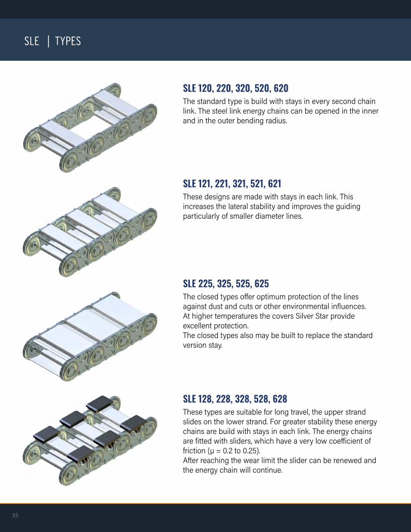
SLE 120, 220, 320, 520, 620The standard type is build with stays in every second chain link. The steel link energy chains can be opened in the inner and in the outer bending radius.
SLE 121, 221, 321, 521, 621These designs are made with stays in each link. Thisincreases the lateral stability and improves the guidingparticularly of smaller diameter lines.
SLE 225, 325, 525, 625The closed types offer optimum protection of the linesagainst dust and cuts or other environmental influences.At higher temperatures the covers Silver Star provideexcellent protection.The closed types also may be built to replace the standardversion stay.
SLE 128, 228, 328, 528, 628These types are suitable for long travel, the upper strand slides on the lower strand. For greater stability these energy chains are build with stays in each link. The energy chains are fitted with sliders, which have a very low coefficient of friction (µ = 0.2 to 0.25).After reaching the wear limit the slider can be renewed andthe energy chain will continue.
35
SLE | TYPES

36w w w . h e n n i g w o r l d w i d e . c o m
SLE | TYPES
SLAThe SLA (SLE with aluminum T-profile or aluminum slot profile) is a highlycustomized and robust energy chain, which is chosen primarily for largerdimensions. The stays are milled in accordance with the requirements of theuser with individual hole patterns.
SLEThe SLE (SLE with plastic inserts or plastic slot-profile) ensures at high speeds a perfect guide and almost excludes errors during installation of the lines. With this design the hole pattern of the stays can be adjusted accurately to the needs of the lines. Plastic inserts are available in a 5 mm grid. The plastic slot-profile can be ordered to suit special requirements.
SLSFor limited installation space, the SLS (SLE with foam slot profile) are used. Again, the optimal guiding of the lines at high speeds and acceleration is ensured. Well known automotive manufacturers have used this type for years with the best experiences. All lines lie in the neutral axis of the energy chain.
SLPFor space reasons, the SLP (SLE with plastic divider PZ and others) can beselected. This inexpensive design allows the guiding of large amounts of cable. The highly variable distribution possibility through small steps of (3mm) in height, plus the Telescopic divider (PT) allows maximum space for all needs, even when changes in cable diameters are required.
SLRThe SLR (SLE with a pipe or roll stays) is manufactured only upon request.The pipe stay allows special material combinations, such as the exclusion of aluminum or the use of stainless steel and brass. The roll bar has advantages particularly for heavy lines with high friction and wear in terms of durability of the cables and hoses: Relative movements on the energy chain are compensated by the rolling motion of the stays.
Compared to standard chains, the SLE series is characterized by the fact that the sturdy aluminum profile can be steplessly adapted to the requirements. Stay lengths of up to 1500 mm can be provided. The subdivision of the interior satisfies every requirement and guarantees optimized cable protection, even at very highaccelerations and travel speeds. For extreme applications, the variants SLA, SLS and SLE should be preferred, since these offer optimize cable guiding. In the case of high speed and acceleration a multi-layerarrangement of the cable should be avoided.
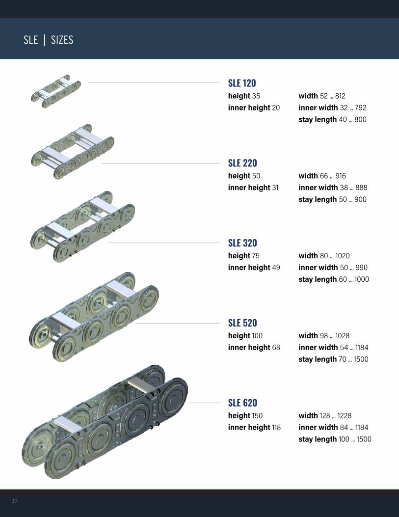
SLE 120height 35 width 52 ... 812inner height 20 inner width 32 ... 792 stay length 40 ... 800
37
SLE | SIZES
SLE 220height 50 width 66 ... 916inner height 31 inner width 38 ... 888 stay length 50 ... 900
SLE 320height 75 width 80 ... 1020inner height 49 inner width 50 ... 990 stay length 60 ... 1000
SLE 520height 100 width 98 ... 1028inner height 68 inner width 54 ... 1184 stay length 70 ... 1500
SLE 620height 150 width 128 ... 1228inner height 118 inner width 84 ... 1184 stay length 100 ... 1500

link connector link singleconnector link doubleconnector angleflange boltradius boltcover plateretaining ringaluminum C-profileserrated screwplastic (vertical) dividerouter coverdistance filler
inner coverband holderband (steel / stainless steel)threaded boltlock washerlocknutplastic insertsfoamslideraluminum-T-profilepipe stayflange rollers
12345678910111213
141516171819202122232425
38w w w . h e n n i g w o r l d w i d e . c o m
SLE | PARTS
❹
⓫
⓬
❸
⓳
❻❺
❿
⓮
❾
❶
⓯
⓱
⓰
❷
❽
⓴
㉔
㉕
㉓
⓭
The use of steel chains with steel bands (16) is limited to energy chains with a maximum length of 6 m and stay length of 600 mm.
㉑
㉒
⓲
❼

39
SLE | ASSEMBLY
❸
❻
❺
❽❼
⓳
⓱
⓲
❹
PACKAGINGWhen removing the packaging and moving the energy chains or parts of them, ensure that the energy chains are free of torsion and tension to avoid mechanical damage.
LENGTHENING OR SHORTENINGIf energy chains are delivered in pieces, proceed with the installation as follows:Push the link together (1) and insert the flange bolts (5) witha shroud (7) in the chain outside. Then build the radius byinserting the radius bolts (6) (see chart for correct radius).Finally put on the inner shroud (7) and fit the retaining ring(8). Roll the energy chain to check that the radius is correctthroughout its length.
Shortening in the reverse order:Loosen the retaining rings (8), pull out the flange bolts (5),lifting the shroud (7), pull the radius bolts (6) and remove the links (1).Energy chains with threaded bolts instead of the retainingrings (8), first unlock the locking plates (18) to solve thelocknuts (19). Thereafter, the threaded bolts (17) and pins(6) can be removed and taken from the links (1).
IMPLEMENT THE CONNECTOR ANGLEThe connector angles (4) are orientated to the outer radiusand to the chain center (normal end mounted). By looseningthe retaining rings (8), drag the flange bolts (5), lift off theshroud (7) and pull the radius bolts (6) the connector angles(4) can be disassembled and placed in a different position.
BENDING RADIUSLoosen the retaining rings (1) and lift off the shrouds (7).Implement the radius bolts (6) according to table (page 20).Then mounting the shrouds (7) and retaining Rings (1).The detachable bolts position for the different radii can befound engraved on the double connector links (3).

40w w w . h e n n i g w o r l d w i d e . c o m
SLE | ASSEMBLY
SLE 120 220 320 520 620
ASSEMBLY OF RADIUS BOLTS
(marking in the outer radius)
(marking in the outer radius)
(marking in the outer radius)
(marking in the outer radius)
(marking in the outer radius)
radius 60 100 150 200 250
radius 100 150 200 250 300
radius 150 200 250 300 400
radius 250 250 300 400 500
radius - 300 400 500 600
the minimum radius isbuilt with only 2 bolts

41
SLE | ASSEMBLY
STAY REMOVALThe stays (9) are fastened with serrated screws (10) to thelinks (1). They can be removed by unscrewing the fourscrews (10).
Stay lengths up to 600 mm are available with quickassembly.
QUICK ASSEMBLYIn quick assembly only two screws must be tightened orloosened. The stays (9) are moved with the groove on the rivet and the serrated screw (10) snapped in the recess andtightened.
COVER SILVER STARThe covers of the closed version can be removed like thestays by loosening the four serrated screws (10).The spacers (13) remain on the links.
STAINLESS STEEL BANDSTo protect the lines against external damage andpollution the chains can be equipped with steel or stainless steel bands in the inner and outer radius. The edges of the steel bands are circular smoothed to avoid injury. Stain-less steel and steel bands are fastened with band holders screwed on sides and with screwed connections on each end of the chain.
⓭
❿
❾❿
❿
❾
normal mounting
quick assemblyrivet bolt
inner band
end mounting
band clip
outerband

42w w w . h e n n i g w o r l d w i d e . c o m
SLE | ASSEMBLY
FINAL ASSEMBLYThe installation height should not fall below the level H = (50 plus two times bend radius plus link height). The pretension of cable carrier is taken into account with the additional space of 50 mm.First fasten fixed connection (F) and then mount the movable connection using the specified bolt size.
Compliance with the maximum free carrying length is of vital importance for the life time of the energy chain, both during the installation as well as when operational. Over travel of the energy chain can lead to damage and premature wear.
If the energy chain is provided with supportelements, the assembly of these must take place before the installation of the chain in order to avoid even a short-term stress point.
An energy chain may never exceed the freecarrying length without support rollers.
The height of the moved connector must beadjusted so that the connector link is moving with a maximum of 5 mm distance from the base of the supporting roller.
MAINTENANCE OF THE CHAINLike every mechanical system this will depend on the ambient conditions so wear will occur which must be observed.For long travels or in a circular motion, the energy chains are often equipped with sliding elements. These allow sliding of the upper part of the chain on a suitable surface (eg, slider, slider-steel, glide bar).The sliders wear depends on the application.The slider surfaces should be checked at regular intervals. With a thickness of 1-2 mm sliders haveto be replaced.

43
SLE | ACCESSORIES
SUPPORT BRACKETS & ROLLERS
• Support rollers are used when half of the travel exceeds the free carrying length.
• Support rollers allow four times extension of travel distance
• Roller Ø100 for all sizes
• The steel support rollers are delivered with robust high quality support frames. The height of the moved connector must be adjusted with a maximum 5mm distance from the base of the supporting roll.
• As an alternative to steel rollers (SR), plastic support rollers (PR) for plastic chains are available.

44w w w . h e n n i g w o r l d w i d e . c o m
SLE | ACCESSORIES
FLANGE ROLLERSThe flange rollers are used for very long chains in combination with a support railing with supporting rollers and support frames
GUIDE ROLLERS FOR STEEL CHAINSGuide rollers are used for steel chains in arrangement u (moving end downside). In this case provide a trough or a corresponding support rail.
GLIDING DISC FOR STEEL CHAINSFor the SLE in arrangement w (lying horizontally on the side) for the longest travel distance or in arrangement k (circular) gliding discs are used. The gliding discs are made of high quality, highly abrasion-resistant materials. In both arrangements a guide is necessary.
SHELF THROUGHS FOR STEEL CHAINSShelf troughs consist of two standard angular channels thatare welded together from 3m lengths. Shelf troughs will beused if a smooth and precise guidance of steel chains isnecessary.
SUPPORT CARRIAGE FOR STEEL CHAINSSteel chains with support carriage are used for long traveldistances and very high additional weights in a counterchainarrangement. With side-mounted guide rollers the energy chains are supported on the support carriage.Technical Features: No push - just pull-tension, large traveldistances, extreme additional loads, smooth running, longlife.

BELL
STABIFLEX CABLE CARRIERS
STABIFLEX cable conduits are moving cablecarriers which have proved successful in a wide range of applications in machine tools and machining centers. The main feature of this closed cable carrier is that through the fitting of a steel band to one of the four sides the flexible conduit can only bend in the one direction where the steel band is situated. In all other directions of movement the conduit remains stable.
STABIFLEX cable conduits are resistant against all cool-ants and lubricants normally used in the machine tool industry.Two qualities are available depending on the traverse speed:
QUALITY GFeaturing a steel band fixed with special glue for speedsof v ≦ 50 m/min.
QUALITY KFeaturing a synthetic band fixed with special glue for speeds of v ≧ 50 m/min.
If no traverse speed is indicated, we automatically choose the G quality.
• To obtain the shortest possible length, it is recommended to have the fixed connection at the midpoint of the stroke.
• When choosing the required type of STABIFLEX, an allowance of at least 10% per cable should be considered.
• Made of zinc plated sheet steel.
• To determine the bending radius (KR), multiply the outer diameter of the cables to be installed by a factor of 8 to 10. However, the minimum bending radius indicated by the cable manufacturers is the main criterion.
• Mounting flanges are welded on both ends of the cable conduit .
• In accordance with safety regulations, electrical continuity is maintained between the flanges and the metal conduit . The cables are loosely guided in the STABIFLEX and fastened at the moving and fixed end.
• To ensure long-term functioning, it is necessary to guide the STABIFLEX in support angles or in a channel the length of which should be approx. 1/2 stroke.
• Max. length of the individual types of Stabiflex is 6.5 m, longer lengths can be flanged together.
h horizontal
v vertical standing
w vertical suspended
z cross beam - top view
functioning
❶❷
❸
FLANGE ARRANGEMENTS
v
h
w
z
45

BELL
L = Ls/2 + 4KR + 50 (mm) *L = Ls/2 + πKR Ls + 2p + 10 (mm) **
* Approximate value** Formula used to calculate the precise length (rounded off to 10 mm)
legend
A x BC x DLfLLsKRHpRA
hose cross section
0.0 30 20 26 16 25 55 120 144 1000 2000 4000 ~ 0.6 ~ 0.1 720 160 1941.0 50 30 43 23 30 110 235 269 1500 3000 6000 ~1.25 ~ 0.2 165 345 3791.1 50 50 45 45 50 110 240 294 2000 4000 8000 ~ 1.7 ~ 0.3 110 240 2902.0 80 45 73 38 45 220 460 510 2000 4000 8000 ~ 2.25 ~ 0.5 275 570 6202.1 85 60 80 55 65 165 350 415 2500 5000 10.000 ~ 2.4 ~ 0.62.2 95 50 90 45 60 130 280 335 2000 4000 8000 ~ 2.9 ~ 0.6 155 335 4003.0 110 60 102 52 60 250 525 590 2500 5000 10.000 ~ 3.6 ~ 1.0 330 685 7503.1 115 80 109 74 80 220 465 550 2500 5000 10.000 ~ 3.8 ~ 1.24.0 170 80 162 72 80 205 435 520 2500 5000 10.000 ~ 5.6 ~1.74.1 175 110 167 102 80 285 600 717 2500 5000 10.000 ~ 5.8 ~ 3.9
StabiflexType
A B C D p KR** RA H Lfmax Ls Ls Weight Weight+0°-20°
(Includes pre-load) withoutsupport
withsupport
hosekg/m
flangeskg/Paar
= STABIFLEX - outside cross-section= STABIFLEX - inside cross-section= Unsupported length= STABIFLEX length= Travel= Bending radius (Tolerance -20%)= Mounting height= Depth of conduit fitted in the flange= Minimum height of support
RA
Ls2
Channel
Ls
Ls2
≥ p + 5 ≥ 5
H
Lf
≥ 5
KR
Ls2
46w w w . h e n n i g w o r l d w i d e . c o m
STABIFLEX CABLE CARRIERS

47
BELL
STABIFLEX CABLE CARRIERS
STANDARD FLANGES
FACE FLANGE TYPE A
f
p
d
c
xe
a
a
b
m
a
d
h
c
g
m
i
p Typeabcdghipm
1.0 54 34 18 7 35 70 55 30 1.52.0 85 50 45 7 65 85 70 45 23.0 115 65 60 9 80 110 90 60 24.0 175 85 95 9 120 130 110 80 2
Typeabcdefpmx
0.0 34 24 13 6 40 50 25 1.5 –1.0 54 34 22 7 45 60 30 1.5 –1.1 54 54 20 7 75 100 50 1.5 –2.0 85 50 50 7 67.5 90 45 2 –2.1 90 65 50 7 117.5 130 65 2 402.2 100 55 50 7 110 120 60 2 403.0 115 65 70 9 90 120 60 2 –3.1 120 85 80 9 142.5 165 80 2 404.0 175 85 100 9 120 160 80 2 –4.1 182 117 140 9 157.5 195 80 3 40

48w w w . h e n n i g w o r l d w i d e . c o m
BELL
c
a
b
d
g
k
m
p
Typeabdghpm
0.0 34 24 6 60 50 25 1.5 1.1 54 54 7 85 85 50 1.5 2.1 90 65 7 120 95 65 2 2.2 100 55 7 130 85 60 2 3.1 120 85 9 150 115 80 2 4.1 182 117 9 210 145 80 3
g
a
h
d
R5
b
m
p
7.5
7.5
FACE FLANGE TYPE B
FACE FLANGE TYPE C
Typeabcdgkpm
1.0 54 34 75 7 90 15 30 1.52.0 85 50 105 7 120 30 45 23.0 115 65 140 9 160 35 60 24.0 175 85 200 9 220 40 80 2

Sales Partner
Service Center
Headquarters / Manufacturing / Distribution / Service Center
Manufacturing / Distribution / Service Center
Manufacturing / Distribution
BELL
HENNIG WORLDWIDE | FACILITIES & CONTACTS
49
❹ Hennig, Inc. Ohio Service Center 11431 Williamson Road Blue Ash, OH 45241 P: + 01 513-247-0838 F: + 01 513-247-0840 [email protected]
❺ Hennig / Gaden, S.A. de C.V. Calzada Abastos Nº 235 Col. Santa María Torreón Coahuila, C.P. 27020 P: + 01 (871) 268 2449 F: + 01 (871) 268 2449 [email protected]
❻ Hennig / Gaden, S.A. de C.V. Calle Primera Nº 1037 Col. Ministro Nazario Ortiz Saltillo, Coahuila, C.P. 25100 P: + 01 (844) 180 0294 F: + 01 (844) 180 029 [email protected]
❶ Hennig, Inc. Global Headquarters 9900 North Alpine Road Machesney Park, IL 61115 P: + 01 815-636-9900 F: + 01 815-636-1988 [email protected]
❷ Hennig, Inc. Oklahoma Service Center 900395 S. 3420 Road Chandler, OK 74834 P: + 01 405-258-6702 F: + 01 405-258-9971 [email protected]
❸ Hennig, Inc. Michigan Service Center 11879 Brookfield Road Livonia, MI 48150 P: + 01 734-523-8274 F: + 01 855-427-1549 [email protected]
❼ Hennig / Gaden, S.A. de C.V. Silca Nº 4, Col. Vista Hermosa Tlalnepantla, Mexico, C.P. 54080 P: + 52 (55) 5318 4146 F: + 52 (55) 5319 32 [email protected]
❽ Cobsen Ltda. R. Benedito Mazulquim, 425 18550-000 Boituva CEP, Brazil P: + 55 15 3263-4042 F: + 55 15 3263-4070 [email protected]
Making our customers successful.

BELL
50
❾ Hennig GmbH European Headquarters Überrheinerstrasse 5 D-85551 Kirchheim, Germany P: + 49 89 96096-0 F: + 49 89 96096-120 [email protected]
❿ Hennig CZ s.r.o. Klánovická 334 250 82 Úvaly, Czech Republic P: + 420 2810 91610 F: + 420 2810 91625 [email protected]
⓫ Hennig France sas (formerly Sermeto) 19, rue de Rebrillon 03300 Creuzier-le-Neuf, France P: +33 470 58 4740 F: + 33 470 58 0022 [email protected]
⓬ Hennig U.K. Ltd. Unit 6, Challenge Close Coventry CV1 5JG, United Kingdom P: + 44 24 76555690 F: + 44 24 76256591 [email protected]
⓭ Hennig BH doo. Ciljuge II bb - poslovna zona 75270 Zivinice, Bosnia Herzegovina P: + 387 35 95 1876 [email protected]
⓮ B & S Industrieel Onderhoud Zirkoonstraat 7, 7554 TT Hengelo (Ov.) Postbus 69 7550 AB Hengelo (Ov.), Netherlands P: + 31 74 8510600 F: + 31 74 8510605 [email protected]
⓯ Svenska Maskinkomponenter AB Brunnsäkersvägen 9 64593 Strängnäs, Sweden P: + 46 8 53470770 F: + 46 8 53470775 [email protected]
⓰ Lubrication Equipment Pty. Ltd. 6, Liebenberg Road, South Africa 1451 Alrode, Johannesburg P: + 27 11 8645785 F: + 27 11 8648231 [email protected]
⓱ Osung Mechatronics Co. Ltd. Jinbuk-myun Shincon-li 413-2 Gyungnam Masan-City, South Korea P: + 82 55 271 1821 F: + 82 55 271 1820 [email protected]
⓲ Enomoto BeA Co. Ltd. 5-10 Sohara Koa-Cho Kakamigahara-Shi, Gifu 504-8551, Japan P: + 81 583 832178 F: + 81 583 897435 [email protected]
w w w . h e n n i g w o r l d w i d e . c o m

Making our customers successful.
www.hennigworldwide.com
Data Subject To Change CC 0121 Printed in the USA Copyright 2021
MAKING OUR CUSTOMERS SUCCESSFULFor over 65 years, Hennig Worldwide has been defining Excellence in Machine Protection, creating regional jobs,
serving their local communities, and supporting the global needs of machine tool customers.
Specializing in chip management, machine protection, facility safety, and generator enclosures,Hennig products optimize production and keep your facility clean and safe.
MACHINEPROTECTIONTelescopic Steel CoversModular Face Shields (XYZ Shields)BellowsAprons & Roll Up CoversWalk-On CoversWiper SystemsTelescopic SpringsCable Conduits
CHIPSOLUTIONSChip ConveyorsTurnkey Chip ManagementConveyor NetworksChip Disc Filtration (CDF)Coolant FiltrationCoolant Tanks
ENCLOSURES &FACILITY SAFETYGENSET EnclosuresMachine EnclosuresPlatforms and StairsGuarding and Fencing3D Printer EnclosuresAdditive Manufacturing Enclo-suresWalk-On Pit CoversScissor Lift BellowsMachine Roof Bellow CoversSpecial Fabrications


![[C9] Hennig-Thurau Hansen Book 2000](https://img.dokumen.tips/doc/110x75/56d6c0711a28ab30169a6cef/c9-hennig-thurau-hansen-book-2000.jpg)