Embed Size (px)
Citation preview

0.6kV - 15kV1000Amp - 5000Amp
CABLE BUSPower for All Voltages

Page Number
Introduction 2
Cable Bus Specification 3
Features & Benefits 4
Technical Information
Electrical Design 6
Parallel Conductors 6
Voltage Drop 6
Shielding 6
System Balance 7
Short-Circuit Capacity 7
Grounding 8
System Cross Sections & Dimensions
600V System 9
5kV System 10
15kV System 10
90° Horizontal Radius Fitting 11
90° Vertical Outside Radius Fitting 11
90° Vertical Inside Radius Fitting 11
Installation 12
System Components 12
Superior ReliabilityYears of field use and independent testing have proven WESCOSA CABLE BUS to be one of the most reliable systems in the market.
Five key features contributing to superior reliability: � n High quality cables are reliable and are
continuous from termination to termination, eliminating faulty splices.
n WESCOSA CABLE BUS utilizes fully insulated conductors that are designed and manufac- tured to withstand the outdoor environment with no further protection of the conduc-tors being required against moisture or sunlight.Since our system design is not affected by moisture and is ventilated for indoor and outdoor applications, it does not require heater strips, filter breathers, or thermostats that competitive technologies require to try and keep moisture out of their systems.
n The system's short circuit capacity has been tested to 100,000RMS symmetrical amperes. Support blocks restrain the cable through-out the entire system.
� n Top and bottom covers are ventilated
for optimum free air rating.Cables in CABLE BUS run cooler than cable in tray or conduit, as well as bus bars in bus duct.
CABLE BUS is an assembly of fully insulated conductors mounted in a ventilated metal housing which maintains designed cable spacing. The welded aluminum alloy enclosure is provided in custom lengths, with each piece sized to fit the specific installation. The system includes all necessary equipment connections, flanges, cable, wall entrance seals, fire stops, elbows, offsets, terminal lugs, termination kits, and assembly hardware. A complete set of match-marked layout drawings shows the location of each section and accessories, for a simple and fast installation.
WESCOSA CABLE BUS is field proven for years to be the most reliable, cost-effective, flexible and maintenance-free power distribution system. Typical applications range from 1000 through 5,000 Amps / 600V,5kV and 15kV. The system is used for a wide range of busway lengths, including relatively short feeders (10—30 feet) through electrical feeders that are several thousand feet long. And WESCOSA CABLE BUS is proven in some of the most extreme environments and conditions including Oil Refineries, Fossil Fuel Burning Facilities, Chemical Plants, Heavy Salt Environments, Hot Areas and Tropical Areas.
Superior performance is achieved by utilizing high quality continuous conductors that are positioned in an engineered spacing and phasing arrangement. This designed spacing and arrangement allows for optimal balance of loads between the conductors, minimized impedance and voltage drop, as well as maximum load carrying capacity through free air rated conductors. The cables are run in parallel without interleaving throughout the entire bus housing, and the system utilizes specific cable support blocks that brace the cables to withstand large momentary short circuit.
WHEN RELIABILITY AND EFFICIENCY ARE A MUST, AND DOWNTIME IS NOT AN OPTION, WESCOSA’S CABLE BUS IS THE SOLUTION FOR YOUR ELECTRICAL BUS DUCT AND ELECTRICAL FEEDER REQUIRE-MENTS.
2
Lowest CostIn most electrical applications over 1,000 amperes, CABLE BUS costs significantly less than non-segregated bus duct or conduit and wire systems. As ampacity or the cost of copper increases, the cost savings of CABLE BUS over other systems is even greater.
Since CABLE BUS is continuous there are no power losses from intermediate splices or connections. CABLE BUS has a lower impedance and lower voltage drop because its conductors are properly phased, spaced and secured in a pre-engineered system. This reduces operating costs by providing long-term energy savings. The use of parallel conductors, combined with our free air rating, allows you to operate fully and efficiently with smaller cables than would be called for with other types of systems.
FlexibilityThe design of WESCOSA CABLE BUS is such that the installation of our system can accommodate unexpected differences between engineering drawings and actual construction, with little or no delay in the project. WESCOSA provides additional cable & CABLE BUS housing to accommodate misplaced equipment in the field. If the placement of equipment requires a shorter bus length, CABLE BUS sections can easily be cut in the field to adjust to the required length.
Cable BusIntroduction
Contents
Cable BusSpecification
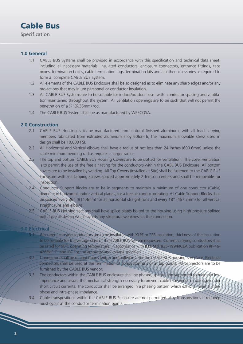
1.0 General1.1 CABLE BUS Systems shall be provided in accordance with this specification and technical data sheet;
including all necessary materials, insulated conductors, enclosure connectors, entrance fittings, taps boxes, termination boxes, cable termination lugs, termination kits and all other accessories as required to form a complete CABLE BUS System.
1.2 All elements of the CABLE BUS Enclosure shall be so designed as to eliminate any sharp edges and/or any projections that may injure personnel or conductor insulation.
1.3 All CABLE BUS Systems are to be suitable for indoor/outdoor use with conductor spacing and ventila-tion maintained throughout the system. All ventilation openings are to be such that will not permit the penetration of a ¼”(6.35mm) rod.
1.4 The CABLE BUS System shall be as manufactured by WESCOSA.
2.0 Construction2.1 CABLE BUS Housing is to be manufactured from natural finished aluminum, with all load carrying
members fabricated from extruded aluminum alloy 6063-T6, the maximum allowable stress used in design shall be 10,000 PSI.
2.2 All Horizontal and Vertical elbows shall have a radius of not less than 24 inches (609.6mm) unless the cable minimum bending radius requires a larger radius.
2.3 The top and bottom CABLE BUS Housing Covers are to be slotted for ventilation. The cover ventilation is to permit the use of the free air rating for the conductors within the CABL BUS Enclosure, All bottom covers are to be installed by welding. All Top Covers (installed at Site) shall be fastened to the CABLE BUS Enclosure with self tapping screws spaced approximately 2 feet on centers and shall be removable for inspection.
2.4 Conductor Support Blocks are to be in segments to maintain a minimum of one conductor (Cable) diameter in horizontal and/or vertical planes, for a free air conductor rating. All Cable Support Blocks shall be spaced every 36” (914.4mm) for all horizontal straight runs and every 18” (457.2mm) for all vertical straight runs and elbows.
2.5 CABLE BUS Housing sections shall have splice plates bolted to the housing using high pressure splined bolts type of design which avoids any structural weakness at the connection.
3.0 Electrical3.1 All current carrying conductors are to be insulated with XLPE or EPR insulation, thickness of the insulation
to be suitable for the voltage class of the CABLE BUS System requested. Current carrying conductors shall be rated for 90˚C operating temperature, in accordance with IEEE Std. 835-1994/ICEA publication #P-46-426/N.E.C. and IEC for the ampacity and voltage specified.
3.2 Conductors shall be of continuous length and pulled in after the CABLE BUS housing is in place. Electrical connectors shall be used at the termination of conductor runs or at tap points. All connectors are to be furnished by the CABLE BUS vendor.
3.3 The conductors within the CABLE BUS enclosure shall be phased, spaced and supported to maintain low impedance and assure the mechanical strength necessary to prevent cable movement or damage under short circuit currents. The conductor shall be arranged in a phasing pattern which exhibits minimal inter-phase and intra-phase imbalance.
3.4 Cable transpositions within the CABLE BUS Enclosure are not permitted. Any transpositions if required must occur at the conductor termination points.
3 4
Cable BusFeatures & Benefits
Reliable s continuous runs of power cable (no faulty splices) from termination to termination.high quality XLPE insulated cables from SAUDI/RIYADH or OMAN Cables.
Lowest Cost Free Air Rating allows greater amperage capacity with less copper, achieving significant cost savings.
gs on materials and installation costs compared to other systems.
Flexible & Adaptable
modate misplacements of equipment that often occur during construction.
of your difficult coordination challenges.
Free Air Rating for Conductors
support blocks.y in accordance with W.E.C. / ICEA & IEC listings for 90 degree Celsius rated conduc-
tors.
Match-Marked Layout Drawings�
correspond to each CABLE BUS section.�
Proper Phase Balance
arrangement that ensures low impedance and low voltage drop.
Indoor or Outdoor Applications
tropical locations.
Labor Savings����

Cable BusSpecification
1.0 General1.1 CABLE BUS Systems shall be provided in accordance with this specification and technical data sheet;
including all necessary materials, insulated conductors, enclosure connectors, entrance fittings, taps boxes, termination boxes, cable termination lugs, termination kits and all other accessories as required to form a complete CABLE BUS System.
1.2 All elements of the CABLE BUS Enclosure shall be so designed as to eliminate any sharp edges and/or any projections that may injure personnel or conductor insulation.
1.3 All CABLE BUS Systems are to be suitable for indoor/outdoor use with conductor spacing and ventila-tion maintained throughout the system. All ventilation openings are to be such that will not permit the penetration of a ¼”(6.35mm) rod.
1.4 The CABLE BUS System shall be as manufactured by WESCOSA.
2.0 Construction2.1 CABLE BUS Housing is to be manufactured from natural finished aluminum, with all load carrying
members fabricated from extruded aluminum alloy 6063-T6, the maximum allowable stress used in design shall be 10,000 PSI.
2.2 All Horizontal and Vertical elbows shall have a radius of not less than 24 inches (609.6mm) unless the cable minimum bending radius requires a larger radius.
2.3 The top and bottom CABLE BUS Housing Covers are to be slotted for ventilation. The cover ventilation is to permit the use of the free air rating for the conductors within the CABL BUS Enclosure, All bottom covers are to be installed by welding. All Top Covers (installed at Site) shall be fastened to the CABLE BUS Enclosure with self tapping screws spaced approximately 2 feet on centers and shall be removable for inspection.
2.4 Conductor Support Blocks are to be in segments to maintain a minimum of one conductor (Cable) diameter in horizontal and/or vertical planes, for a free air conductor rating. All Cable Support Blocks shall be spaced every 36” (914.4mm) for all horizontal straight runs and every 18” (457.2mm) for all vertical straight runs and elbows.
2.5 CABLE BUS Housing sections shall have splice plates bolted to the housing using high pressure splined bolts type of design which avoids any structural weakness at the connection.
3.0 Electrical3.1 All current carrying conductors are to be insulated with XLPE or EPR insulation, thickness of the insulation
to be suitable for the voltage class of the CABLE BUS System requested. Current carrying conductors shall be rated for 90˚C operating temperature, in accordance with IEEE Std. 835-1994/ICEA publication #P-46-426/N.E.C. and IEC for the ampacity and voltage specified.
3.2 Conductors shall be of continuous length and pulled in after the CABLE BUS housing is in place. Electrical connectors shall be used at the termination of conductor runs or at tap points. All connectors are to be furnished by the CABLE BUS vendor.
3.3 The conductors within the CABLE BUS enclosure shall be phased, spaced and supported to maintain low impedance and assure the mechanical strength necessary to prevent cable movement or damage under short circuit currents. The conductor shall be arranged in a phasing pattern which exhibits minimal inter-phase and intra-phase imbalance.
3.4 Cable transpositions within the CABLE BUS Enclosure are not permitted. Any transpositions if required must occur at the conductor termination points.
3 4
Cable BusFeatures & Benefits
Reliable s continuous runs of power cable (no faulty splices) from termination to termination.high quality XLPE insulated cables from SAUDI/RIYADH or OMAN Cables.
Lowest Cost Free Air Rating allows greater amperage capacity with less copper, achieving significant cost savings.
gs on materials and installation costs compared to other systems.
Flexible & Adaptable
modate misplacements of equipment that often occur during construction.
of your difficult coordination challenges.
Free Air Rating for Conductors
support blocks.y in accordance with W.E.C. / ICEA & IEC listings for 90 degree Celsius rated conduc-
tors.
Match-Marked Layout Drawings�
correspond to each CABLE BUS section.�
Proper Phase Balance
arrangement that ensures low impedance and low voltage drop.
Indoor or Outdoor Applications
tropical locations.
Labor Savings����

5 6
Selection of the proper CABLE BUS system must be undertaken with care to assure that it compliments the design of the overall electrical power system.
ELECTRICAL DESIGNTo ensure an efficient, dependable, high quality installation, every WESCOSA CABLE BUS System is engineered fully with particular emphasis placed on CABLES, SYSTEM BALANCE, SHORT CIRCUIT CAPABILITY and GROUNDING REQUIREMENTS. Each one of these key design considerations must be analyzed separately to determine how they affect the overall system design.
PARALLEL CONDUCTORSParallel conductors (more than one per phase) can be used to an advantage in CABLE BUS where large conductor sizes are encountered. The ampacity per circular mil of conductor decreases as the circular mil of conductor increases. Smaller conductors running parallel are more flexible during installation and have greater current carrying capability than fewer, larger conductors.
VOLTAGE DROPProper system design dictates that voltage drop be considered for both the power feeders separately as well as the entire power system.
An approximate line to neutral voltage drop can be calculated by using the following formula:
V.D.L-N = I (R COS Ø + X SIN Ø)
% V.D. = KVA (R COS Ø + X SIN Ø) 10 (KV)2
SHIELDINGShielding is used on power cables to confine the dielectric field of the conductor to the cable insulation. Shielded Power Cables are used in CABLE BUS for applications above 2500 volts and when any of the following conditions exist:
1. Where cables are subject to soot or other heavy deposits that may form paths to ground.2. Where electrostatic discharge can effect nearby computerized control cables or other low level signals.3. Concern for Personnel safety.
When installing shielded cable the metallic shielding must be solidly grounded and the installation must be studied to determine the best grounding method. This is necessary as voltage is induced in the shield of a single conductor cable carrying alternating current due to mutual inductance between its shield and any other conductor in its vicinity. This induced voltage can result in two conditions:
1. Metal shields bonded or grounded at more than one point have circulating currents flowing in them. The magnitude of the circulating currents depends on the mutual inductance to the other cables, the current in these conductors, and the resistance of the shield.
2. Shields bonded or grounded at only one point will have a voltage build up in the sheath.
Less Support Material
Safe
Complete System
NEMA 4).
Factory Fabricated—All Welded
Testing and Certification Heat-Rise Test Report is available upon request.
Cable BusTechnical Information
Cable BusFeatures & Benefits
7 8
SYSTEM BALANCECABLE BUS is a power distribution system using single conductor insulated power cables and support blocks to maintain cable spacing. Each phase consists of one or more cables connected in parallel. The complete assembly is enclosed in a ventilated aluminum or steel enclosure for support and protection.
Parallel conductor transmission lines, using widely spaced conductors, have been in use for many years. The electrical coupling between the conductors of a parallel conductor system, which is a function of the geometry of the location of the conductors, can cause an imbalance in the conductor currents. In a widely spaced overhead transmission line transposition of conductors can economically be used to balance the conductor currents.
The spacing of the conductors in CABLE BUS is one cable diameter, (i.e. one to three inches), as compared to the typical value of thirty feet used in overhead lines. This close spacing and the relatively short lengths, as compared to hundreds of miles for overhead lines, make the transposition of conductors for balancing purposes a practical impossibility.
The objective of the CABLE BUS design was to obtain the optimum balance for an electrical circuit using parallel conductors (no transposition) with close spacing. WESCOSA has designed CABLE BUS Systems with minimal imbalance.
WESCOSA CABLE BUS is designed for balance of conductors within a phase (intra-phase) and balance between the phases (inter-phase). Many phasing arrangements will provide inter-phase balance of currents due to the load impedance, but the majority of these phasing arrangements provide intra-phase current imbalance.
as intra-phase current balance, therefore reducing the amount of parallel conductor imbalance to a minimum.
SHORT CIRCUIT CAPACITYA CABLE BUS system must be able to withstand the dangerous mechanical forces created by short circuit currents. These forces are transmitted from the conductors to the cable supports. In the case of CABLE BUS, the support elements include the support blocks and enclosure.
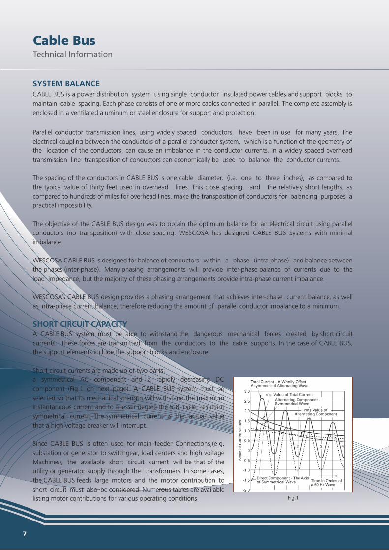
Short circuit currents are made up of two parts;a symmetrical AC component and a rapidly decreasing DC component (Fig.1 on next page). A CABLE BUS system must be selected so that its mechanical strength will withstand the maximum instantaneous current and to a lesser degree the 5-8 cycle resultant symmetrical current. The symmetrical current is the actual value that a high voltage breaker will interrupt.
Since CABLE BUS is often used for main feeder Connections,(e.g. substation or generator to switchgear, load centers and high voltage Machines), the available short circuit current will be that of the utility or generator supply through the transformers. In some cases, the CABLE BUS feeds large motors and the motor contribution to short circuit must also be considered. Numerous tables are available listing motor contributions for various operating conditions.
Available fault currents can be limited to some extent by conductor impedance. The impedance can be in the form of either conductor length, size or a combination of both.
The WESCOSA CABLE BUS design ignores these added conductor impedance; instead the worst fault conditions are always assumed. For design consideration a three phase short circuit current will result in the maximum mechanical forces for design considerations.
If CABLE BUS is fed directly from the utility company service then short circuit current data will be available from the utility.Where CABLE BUS is connected to the transformer secondary the three-phase fault current can be calculated using the following formula:
I = KVA x 1000 x 100 1.73 x E x Z I = RMS Symmetrical Fault Current KVA = Transformer Rating E = Secondary Voltage of Transformers Z = Impedance of Transformer in Percent
Where motor contributions are considered, the fault current due to the motor feedback will be a function of the voltage and is usually expressed as multiples of the motor full load current. NEMA standards are available which list these factors. Certified tests have been conducted to determine the short circuit performance of CABLE BUS using various supporting arrangements.
SHORT CIRCUIT TESTINGThe tests performed on the 15KV/4KA CABLE BUS were conducted similar to the tests outlined in IEEE C37.23.
to 634 volts. One end of the BABLE BUS was connected to the source terminals and the other was short circuited to create a three phase bolted fault.
currents greater than 200,000 amperes. CABLE BUS withstood the mechanical forces of the test without any damage to the cables, support blocks or enclosure.
GROUNDINGA CABLE BUS system must afford protection to life and property against faults caused by electrical disturbance. Lightning, electrical system failures, as well as failures in the system corrected equipment all constitute possible fault hazard locations.
For this reason, all metal enclosures of the system, as well as non-current carrying or neutral conductors should be tied together and reduced to a common potential. This includes the structural steel of the building, water, steam and gas piping.
There are two distinct divisions to the system and equipment grounding problem. The system ground is the connection of the distribution system to earth by means of a neutral or grounded conductor and system grounding serves to limit the voltage, which might appear on a circuit due to lightning or accidental contact.
Cable BusTechnical Information
Cable BusTechnical Information
Fig.1
7 8
SYSTEM BALANCECABLE BUS is a power distribution system using single conductor insulated power cables and support blocks to maintain cable spacing. Each phase consists of one or more cables connected in parallel. The complete assembly is enclosed in a ventilated aluminum or steel enclosure for support and protection.
Parallel conductor transmission lines, using widely spaced conductors, have been in use for many years. The electrical coupling between the conductors of a parallel conductor system, which is a function of the geometry of the location of the conductors, can cause an imbalance in the conductor currents. In a widely spaced overhead transmission line transposition of conductors can economically be used to balance the conductor currents.
The spacing of the conductors in CABLE BUS is one cable diameter, (i.e. one to three inches), as compared to the typical value of thirty feet used in overhead lines. This close spacing and the relatively short lengths, as compared to hundreds of miles for overhead lines, make the transposition of conductors for balancing purposes a practical impossibility.
The objective of the CABLE BUS design was to obtain the optimum balance for an electrical circuit using parallel conductors (no transposition) with close spacing. WESCOSA has designed CABLE BUS Systems with minimal imbalance.
WESCOSA CABLE BUS is designed for balance of conductors within a phase (intra-phase) and balance between the phases (inter-phase). Many phasing arrangements will provide inter-phase balance of currents due to the load impedance, but the majority of these phasing arrangements provide intra-phase current imbalance.
as intra-phase current balance, therefore reducing the amount of parallel conductor imbalance to a minimum.
SHORT CIRCUIT CAPACITYA CABLE BUS system must be able to withstand the dangerous mechanical forces created by short circuit currents. These forces are transmitted from the conductors to the cable supports. In the case of CABLE BUS, the support elements include the support blocks and enclosure.
Short circuit currents are made up of two parts;a symmetrical AC component and a rapidly decreasing DC component (Fig.1 on next page). A CABLE BUS system must be selected so that its mechanical strength will withstand the maximum instantaneous current and to a lesser degree the 5-8 cycle resultant symmetrical current. The symmetrical current is the actual value that a high voltage breaker will interrupt.
Since CABLE BUS is often used for main feeder Connections,(e.g. substation or generator to switchgear, load centers and high voltage Machines), the available short circuit current will be that of the utility or generator supply through the transformers. In some cases, the CABLE BUS feeds large motors and the motor contribution to short circuit must also be considered. Numerous tables are available listing motor contributions for various operating conditions.
Available fault currents can be limited to some extent by conductor impedance. The impedance can be in the form of either conductor length, size or a combination of both.
The WESCOSA CABLE BUS design ignores these added conductor impedance; instead the worst fault conditions are always assumed. For design consideration a three phase short circuit current will result in the maximum mechanical forces for design considerations.
If CABLE BUS is fed directly from the utility company service then short circuit current data will be available from the utility.Where CABLE BUS is connected to the transformer secondary the three-phase fault current can be calculated using the following formula:
I = KVA x 1000 x 100 1.73 x E x Z I = RMS Symmetrical Fault Current KVA = Transformer Rating E = Secondary Voltage of Transformers Z = Impedance of Transformer in Percent
Where motor contributions are considered, the fault current due to the motor feedback will be a function of the voltage and is usually expressed as multiples of the motor full load current. NEMA standards are available which list these factors. Certified tests have been conducted to determine the short circuit performance of CABLE BUS using various supporting arrangements.
SHORT CIRCUIT TESTINGThe tests performed on the 15KV/4KA CABLE BUS were conducted similar to the tests outlined in IEEE C37.23.
to 634 volts. One end of the BABLE BUS was connected to the source terminals and the other was short circuited to create a three phase bolted fault.
currents greater than 200,000 amperes. CABLE BUS withstood the mechanical forces of the test without any damage to the cables, support blocks or enclosure.
GROUNDINGA CABLE BUS system must afford protection to life and property against faults caused by electrical disturbance. Lightning, electrical system failures, as well as failures in the system corrected equipment all constitute possible fault hazard locations.
For this reason, all metal enclosures of the system, as well as non-current carrying or neutral conductors should be tied together and reduced to a common potential. This includes the structural steel of the building, water, steam and gas piping.
There are two distinct divisions to the system and equipment grounding problem. The system ground is the connection of the distribution system to earth by means of a neutral or grounded conductor and system grounding serves to limit the voltage, which might appear on a circuit due to lightning or accidental contact.
Cable BusTechnical Information
Cable BusTechnical Information
Fig.1

9 10
CABLE BUS systems should be grounded to substation structure and thus to the substation ground grid and to the building steel by means of the CABLE BUS support materials. CABLE BUS should also be grounded to the equipment or switchgear enclosure by means of a box connector.
It is an accepted fact that ground currents tend to concentrate near power conductors and that cable enclosures take a large portion of the ground currents; therefore, it is important to consider CABLE BUS as a major carrier of ground currents.
System Cross Sections & Dimensions
NEC/IEC 600V
NEC/IEC 5kV
NEC/IEC 15kV
TYPICAL HEIGHT WIDTHAMPACITY (H) (W)
1000A 203mm (8”) 356mm (14”)1200A 203mm (8”) 356mm (14”)1600A 203mm (8”) 508mm (20”)2000A 203mm (8”) 508mm (20”)2500A 203mm (8”) 508mm (20”)3000A 254mm (10”) 508mm (20”)3200A 254mm (10”) 508mm (20”)3500A 254mm (10”) 508mm (20”)4000A 254mm (10”) 661mm (26”)5000A 254mm (10”) 661mm (26”)
TYPICAL HEIGHT WIDTHAMPACITY (H) (W)
1000A 203mm (8”) 356mm (14”)1200A 203mm (8”) 356mm (14”)1600A 203mm (8”) 508mm (20”)2000A 203mm (8”) 508mm (20”)2500A 203mm (8”) 508mm (20”)3000A 203mm (8”) 508mm (26”)3500A 254mm (10”) 661mm (26”)4000A 254mm (10”) 661mm (26”)5000A 254mm (10”) 712mm (28”)
TYPICAL HEIGHT WIDTHAMPACITY (H) (W)
1000A 203mm (8”) 356mm (14”)1200A 203mm (8”) 356mm (14”)1600A 203mm (8”) 508mm (20”)2000A 203mm (8”) 661mm (26”)2500A 203mm (8”) 661mm (26”)3000A 305mm (10”) 661mm (26”)3500A 305mm (12”) 661mm (26”)4000A 305mm (12”) 712mm (28”)5000A 305mm (12”) 813mm (32”)
n Systems shown are 3 Phase / 3 Wire without system ground.n Systems can be 3 Phase / 4 Wire with full, half or partial neutral with/without a system ground.n Combining circuits within the same enclosure is available.n For additional amperage and voltage requirements please contact the factory.
Cable BusSystem Cross Sections & Dimensions
Cable BusTechnical Information

11 12
The following techniques are suggested to pull cables into place:
Cables with an O.D. larger than 2” can be pulled by pulling eye or a basket grip.
If the strain does not elongate or damage the insulation then short lengths and small diameter cables may be pulled with a basket grip only.
Long lengths of conductor (up to 1,000 ft.), with as many as a dozen bends, should be pulled in one continuous operation at a speed of 20 to 25 ft. per minute. It may be necessary to employ a braked reel to reduce sagging of the conductor between horizontal rollers. The most economical spacing of horizontal rollers depends on the weight of cable to be pulled. In general, the spacing of horizontal rollers should range between approximately 10 ft. for cable weighing over 8 pounds per foot and 16 feet for cable weighing less than 2 pounds per foot.
90° Horizontal Radius Fitting
90° Vertical Outside Radius Fitting
90° Vertical Inside Radius Fitting
*Radii shown are to outside flange. Cable radius will be nominal radius or greater.
*Radii shown are to outside flange. Cable radius will be nominal radius or greater.
*Radii shown are to outside flange. Cable radius will be nominal radius or greater.
Nominal CABLE BUS Height Inside Radius Outside Radius
Radius “H” “R1” “R2”
203mm (8”) 305mm (12”) 508mm (20”)
12” 254mm (10”) 305mm (12”) 559mm (22”)
305mm (12”) 305mm (12”) 610mm (24”)
203mm (8”) 457mm (18”) 660mm (26”)
18” 254mm (10”) 457mm (18”) 711mm (28”)
305mm (12”) 457mm (18”) 762mm (30”)
203mm (8”) 610mm (24”) 813mm (32”)
24” 254mm (10”) 610mm (24”) 864mm (34”)
305mm (12”) 610mm (24”) 915mm (36”)
Nominal CABLE BUS Height Inside Radius Outside Radius
Radius “H” “R1” “R2” 203mm (8”) 305mm (12”) 508mm (20”)12” 254mm (10”) 305mm (12”) 559mm (22”) 305mm (12”) 305mm (12”) 610mm (24”) 203mm (8”) 457mm (18”) 660mm (26”)18” 254mm (10”) 457mm (18”) 711mm (28”) 305mm (12”) 457mm (18”) 762mm (30”) 203mm (8”) 660mm (24”) 813mm (32”)24” 254mm (10”) 660mm (24”) 864mm (34”) 305mm (12”) 660mm (24”) 915mm (36”)
Nominal CABLE BUS Width Inside Radius Outside RadiusRadius “W”(Total) “R1” “R2” 356mm (14”) 279mm (11”) 635mm (25”)12” 508mm (20”) 279mm (11”) 787mm (31”) 661mm (26”) 279mm (11”) 940mm (37”) 356mm (14”) 432mm (17”) 788mm (31”) 508mm (20”) 432mm (17”) 940mm (37”)18” 661mm (26”) 432mm (17”) 1093mm (43”) 712mm (28”) 432mm (17”) 1144mm (45”) 356mm (14”) 584mm (23”) 940mm (37”) 508mm (20”) 584mm (23”) 1093mm (43”)24” 661mm (26”) 584mm (23”) 1245mm (49”) 712mm (28”) 584mm (23”) 1296mm (51”) 813mm (32”) 584mm (23”) 1397mm (55”)
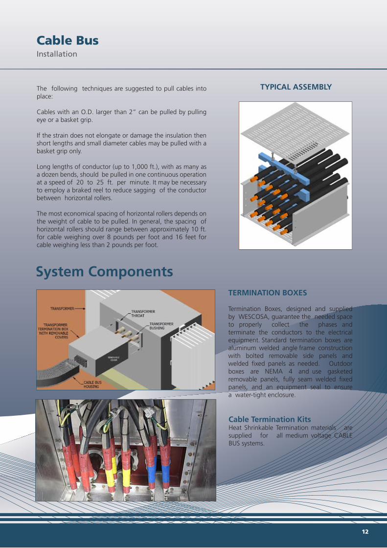
TYPICAL ASSEMBLY
System ComponentsTERMINATION BOXES
Termination Boxes, designed and supplied by WESCOSA, guarantee the needed space to properly collect the phases and terminate the conductors to the electrical equipment. Standard termination boxes are aluminum welded angle frame construction with bolted removable side panels and welded fixed panels as needed. Outdoor boxes are NEMA 4 and use gasketed removable panels, fully seam welded fixed panels, and an equipment seal to ensure a water-tight enclosure.
Cable Termination KitsHeat Shrinkable Termination materials are supplied for all medium voltage CABLE BUS systems.
Cable BusInstallation
Cable BusDesign Cross Sections & Dimensions
11 12
The following techniques are suggested to pull cables into place:
Cables with an O.D. larger than 2” can be pulled by pulling eye or a basket grip.
If the strain does not elongate or damage the insulation then short lengths and small diameter cables may be pulled with a basket grip only.
Long lengths of conductor (up to 1,000 ft.), with as many as a dozen bends, should be pulled in one continuous operation at a speed of 20 to 25 ft. per minute. It may be necessary to employ a braked reel to reduce sagging of the conductor between horizontal rollers. The most economical spacing of horizontal rollers depends on the weight of cable to be pulled. In general, the spacing of horizontal rollers should range between approximately 10 ft. for cable weighing over 8 pounds per foot and 16 feet for cable weighing less than 2 pounds per foot.
90° Horizontal Radius Fitting
90° Vertical Outside Radius Fitting
90° Vertical Inside Radius Fitting
*Radii shown are to outside flange. Cable radius will be nominal radius or greater.
*Radii shown are to outside flange. Cable radius will be nominal radius or greater.
*Radii shown are to outside flange. Cable radius will be nominal radius or greater.
Nominal CABLE BUS Height Inside Radius Outside Radius
Radius “H” “R1” “R2”
203mm (8”) 305mm (12”) 508mm (20”)
12” 254mm (10”) 305mm (12”) 559mm (22”)
305mm (12”) 305mm (12”) 610mm (24”)
203mm (8”) 457mm (18”) 660mm (26”)
18” 254mm (10”) 457mm (18”) 711mm (28”)
305mm (12”) 457mm (18”) 762mm (30”)
203mm (8”) 610mm (24”) 813mm (32”)
24” 254mm (10”) 610mm (24”) 864mm (34”)
305mm (12”) 610mm (24”) 915mm (36”)
Nominal CABLE BUS Height Inside Radius Outside Radius
Radius “H” “R1” “R2” 203mm (8”) 305mm (12”) 508mm (20”)12” 254mm (10”) 305mm (12”) 559mm (22”) 305mm (12”) 305mm (12”) 610mm (24”) 203mm (8”) 457mm (18”) 660mm (26”)18” 254mm (10”) 457mm (18”) 711mm (28”) 305mm (12”) 457mm (18”) 762mm (30”) 203mm (8”) 660mm (24”) 813mm (32”)24” 254mm (10”) 660mm (24”) 864mm (34”) 305mm (12”) 660mm (24”) 915mm (36”)
Nominal CABLE BUS Width Inside Radius Outside RadiusRadius “W”(Total) “R1” “R2” 356mm (14”) 279mm (11”) 635mm (25”)12” 508mm (20”) 279mm (11”) 787mm (31”) 661mm (26”) 279mm (11”) 940mm (37”) 356mm (14”) 432mm (17”) 788mm (31”) 508mm (20”) 432mm (17”) 940mm (37”)18” 661mm (26”) 432mm (17”) 1093mm (43”) 712mm (28”) 432mm (17”) 1144mm (45”) 356mm (14”) 584mm (23”) 940mm (37”) 508mm (20”) 584mm (23”) 1093mm (43”)24” 661mm (26”) 584mm (23”) 1245mm (49”) 712mm (28”) 584mm (23”) 1296mm (51”) 813mm (32”) 584mm (23”) 1397mm (55”)
TYPICAL ASSEMBLY
System ComponentsTERMINATION BOXES
Termination Boxes, designed and supplied by WESCOSA, guarantee the needed space to properly collect the phases and terminate the conductors to the electrical equipment. Standard termination boxes are aluminum welded angle frame construction with bolted removable side panels and welded fixed panels as needed. Outdoor boxes are NEMA 4 and use gasketed removable panels, fully seam welded fixed panels, and an equipment seal to ensure a water-tight enclosure.
Cable Termination KitsHeat Shrinkable Termination materials are supplied for all medium voltage CABLE BUS systems.
Cable BusInstallation
Cable BusDesign Cross Sections & Dimensions

13 14
BUS END FLANGEBox connectors are used to terminate CABLE BUS at switchgear or other metal structures for indoor applications and are furnished with all necessary hardware.
WATERTIGHT SEALSSeal Flange
These fittings form a seal with walls and can also be used for floor penetrations that must be watertight. Conductors are sealed with RTV silicone sealant. Entrance fittings are furnished with all necessary hardware.
MCTFIRESTOP/WATERTIGHT SEAL
MCT seals are used when an absolutely watertight fitting is required. Neoprene blocks are inserted after the cables are installed for ease of pulling. They are UL listed for a 2 hour fire rating and come with all necessary hardware.
Tap BoxesTap boxes allow for intermediate load tapping.
The design provides system voltage rated air
separation between live parts and adjacent
surfaces to eliminate the necessity of tapping all
energized components.
Electrical ConnectorsTwo Hole Long barrel compression type lugs and Silicone bronze termination hardware are supplied with each project to ensure reliable connection with electrical equip-ment.
The tap box consists of:Aluminum framed enclosure Removable covers (gasketed for outdoor applications) Porcelain or Epoxy post stand off insulators Bus bars
Cable BusSystem Components
Cable BusSystem Components
Cable BusSystem Components

0.6kV - 15kV1000Amp - 5000Amp
CABLE BUSPower for All Voltages