Embed Size (px)
Citation preview
AD-A1O? 445 EXOTECH PTY LTD MONTEREY CA F/6 21/5MULTISTAGE AXIAL COMPRESSOR PROGRAM ON TIP CLEARANCE EFFECTS(U)AUG 81 1 MOYLE N62271-8O-N-25U4
UNCLASSIFIED NPS-67-81-01CR NL ,IIIIIIIIIIIIIIIINllfIlfllffflllfIIIloommI///lFET1DfluDEIHEE
11. J2 2.2
11111 _1__2__
1111111.12
* MI.fCOCOPY Rt'SOLUNON TIS L UARJ
NS-1 LEVEL
NAVAL POSTGRADUATE SCHOOLMonterey, California
CONTRACTOR REPORT
Progress Report - Multistage Axial CompressorProgram on Tip Clearance Effects
Ixotle DTIEoehPty Lt.ELECT
Monterey Business Center, Box 3060Monterey, California 93940 NOV 18 19
August 1981 D
Approved for public release; distribution unlimited
Prepared for:
Naval Postgraduate SchoolMonterey, California 93940
y\.
, , I I . .. ... o

NAVAL POSTGRADUATE SCHOOL
Monterey, California
Rear Admiral J. J. Ekelund D. A. SbradySuperintendent Acting Provost
The work reported herein was carried out for the Naval Post-graduate School by Exotech Pty. Ltd. under Contract NumberN62271-80-N-2504. The work was part of a progam entitledMulti-Stage Compressor Study funded in part by the FoundationResearch Program at the Naval Postgraduate School.
This report was prepared by:
Mnterey Butimess CenterBox 3060Monterey, California 93940
Publication of the report does not constitute approval of thesponsor for the findings or conclusions. It is published forinformation and for the exchange and stimulation of ideas.
Reviewed by:
R. P. Shreeve, Director M. F. Platzer, CfazmanTurbopropulsion Laboratory Department of Aeronautics
Released by:
W. M. Toll..Dean of Research
# ',,
UNCLASSIFIED __
_II RITY CL A .SII'ICATION 3FP THgIS PAGE (When Date Entered)
N7'C REPRT DCUMNTATON AGEREAD INSTRUCTIONSREPOT DCUMNTATON AGEBEFORE COMPLETING FORM
O4-JLEAT NUMBER A3. GOVT ACCESSION NO. 3. IPIENT'S CATALOG NUMBER
NS67-81-0lC >A 10 l1 04 TITLE OvAnd S.btirt ~ . ~ oCOVERED
Progess epot-- /Multistage Axial Compressor Contractor ,e wt,P-rogram on Tip Clearance Effects., Ma 79Ag wf81
7 Au~mR~s) . CONTRACT OR GRANT NUMSER(f)
9 PERFORMING ORGANIZATION NAME AND ADDRESS 10. PROGRAM ELEMENT PROJECT. TASK
Exotech Pty Ltd. ARA&WR NTNUNGERS
Monterey Business Center, Box 3060Monterey, California 93940
II. CONTROLLING OFFICE NAME AND ADDRESS 1~-\2. REPORT DATE
Naval Postgraduate School L-'AU §-±- 98 1Monterey, CA 93940 ii. - UMBER OF PAGES
14. MONITORING AGEN4CY NAME ADORESSIf different teom Controlling 0111ce)44. EC'URITV CLASS. (at ti report)
UNCLASSIFIED
15a. OECLASSI F1 CATION/ DOWNGRADINGSCHEDULE
16. DISTRIBUTION4 STATEMENT (of this Rieport)
Approved for Public Release; distribution unlimited
17. OISTRIOUTION STATEMENT (of th. abstract ffntorodIn Block 20. it different from Report)
19. SUPPLEMENTARY NOTES
Progress Report. Principal Investigator, Dr. R. P. Shreeve, Director,Turbopropulsion Laboratory, Naval Postgraduate School, Monterey, California,93940
It. KEY WORDS (Contlenue an reverse side it neesay and Identify by block nmber)
Axial CompressorsTip Clearance Effects
Compressor Blading
20. AGSTRACT (Centiman i reverse sld. lifnete.v and Ideerlft' bp blook mmnbe)
DD I j APO73 1473 tDITION of, Nov6so is OUSai-ETE UNCLASSIFIEDS/N 0102,014-6601
SECURITY CLASSIFICATION OF TNIWPIACE (ftea Da Enter")
TABLE OF CONTENTS
Page
1. INTRODUCTION ............. ........... 1
1.1 Design Problem Statement .... .......... 2
2. REVIEW OF PAST APPROACHES TO TIP CLEARANCE EFFECTS 4
2.1 Approaches Using Machine Relative PressureGradients ......... ................. 4
2.2 Approaches Using Blade Relative Pressure
Gradients ......... .................. 5
2.3 Comparison of the Co-Ordinate Systems . . .. 6
2.4 Correlations of Tip Clearance on MachineStages ...... ................... 6
2.5 Summary ......... ................... 6
3. CURRENT APPROACH TO TIP CLEARANCE EFFECTS . . . 8
3.1 Influence of Blade Class on Primary Flow . . 8
3.2 Measurement of Secondary Flow by Blade Class/Type ....... ..................... 9
3.3 The Multistage Compressor Facility ... . . 10
3.4 Facility Parameter Variations .. ........ . 11
3.5 The Experimental Approach ... .......... . 12
4. WORK COMPLETED AND RESULTS TO DATE .. ........ . 14
4.1 Survey of Literature on Tip Clearance and TipFlows . . . . . . . . ... . . . . . . . . . 14
4.2 Blade Aero-Mechanical Design .. ........ .. 15
4.3 Epoxy Blade and Blade Mold Fabrication . . . 16
4.4 Blade Finishing and Installation . ...... . 18
4.5 Data Acquisition Systems .. .......... . 19
ii
4.6 Probe and Instrumentation Development . . . 20
4.7 Baseline Testing ..... .............. . 21
5. CONCLUSION ...... ................... . 23
6. REFERENCES ....... ................... 39
Accession ? r
-Tis -GRA&IDTIC TABUnannounced 0Justifi Cato
By--Distribution/.
Avallability Codes
Avail and/or -
Dist special
rNO iii
. .. .. .

LIST O FIGURES
Page
Figure 2.4(1) Extract from Koch (see Author Refer-ences) showing increase in static pressure risewith reducing tip gap ..... ............... .. 24
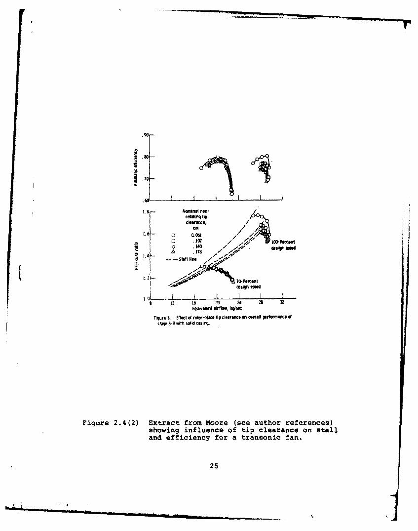
Figure 2.4(2) Extract from Moore (see Author Refer-ences) showing influence of tip clearance onstall and efficiency for a transonic flow ...... .. 25
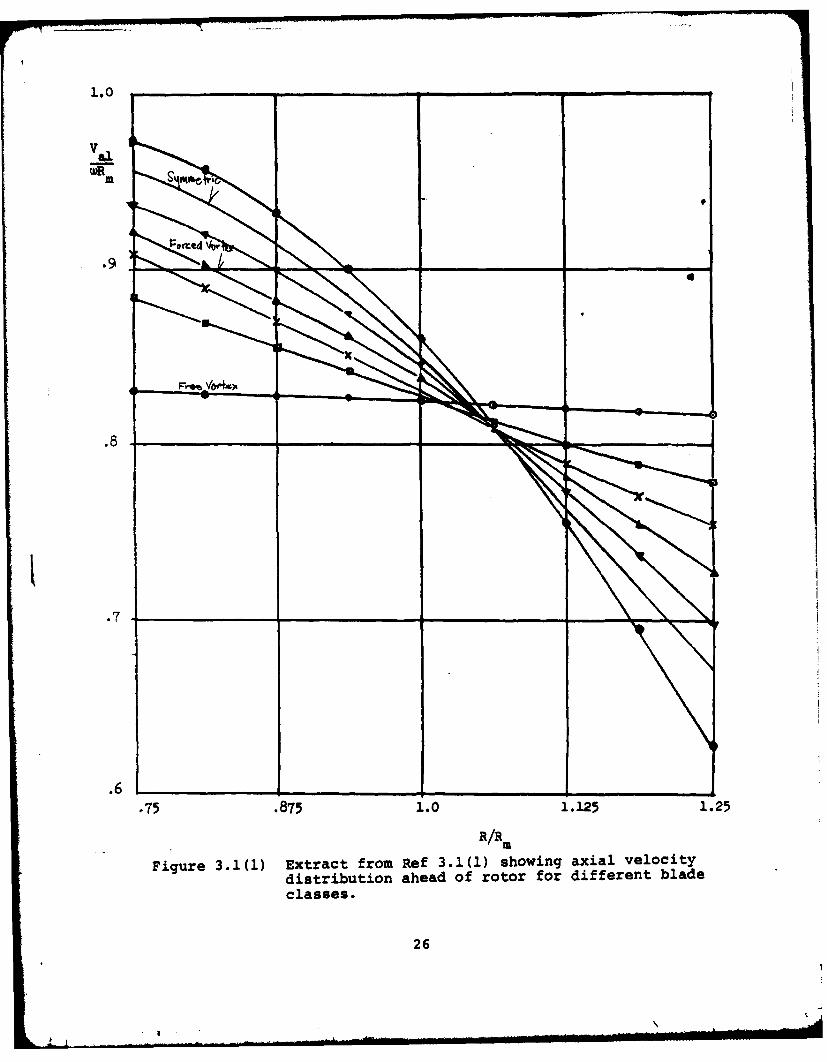
Figure 3.1(1) Extract from Ref 3.1(1) showing axialvelocity distribution ahead of rotor for differ-ent blade classes ...... ................. .. 26
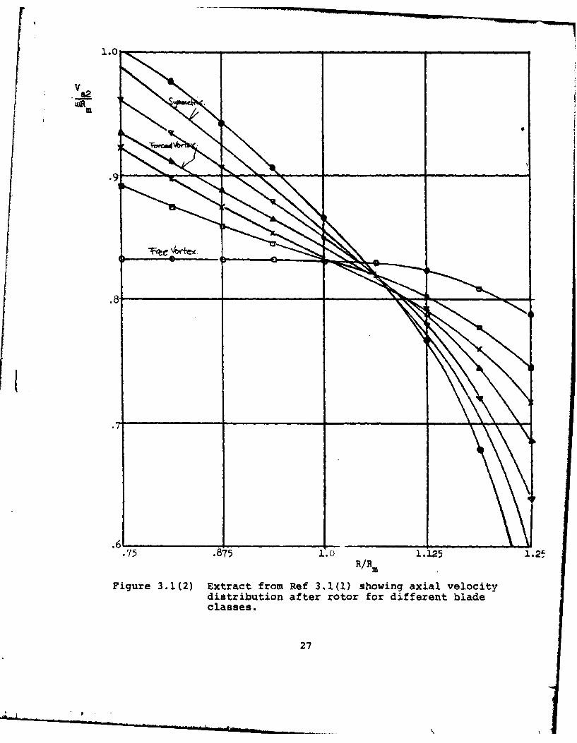
Figure 3.1(2) Extract from Ref 3.1(1) showing axialvelocity distribution after rotor for differentblade classes ....... ................... .. 27
Figure 4.2(1) Stress levels at blade root as afunction of speed compared with material safestresses ......... ..................... .28
Figure 4.5(1) Schematic layout of steady state dataacquisition system ....................... .29
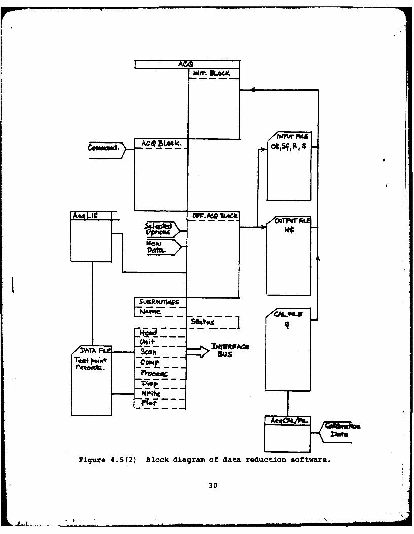
Figure 4.5(2) Block diagram of data reduction soft-ware ......... ....................... .. 30
Figure 4.6(1) Measurement errors for Scanivalvetransducer when used to measure differentialpressures ........ ..................... .. 31
Figure 4.6(2) Sketch of circumferential rake ....... 32
Figure 4.7(1) Preliminary results for single stagesymmetric blading ...... ................. .. 33
iv
7
LIST OF PLATES
Page
Plate 3.2(2) Extract from Ref 3.2(2) showing stageblading with twisted ends .... ............. ... 34
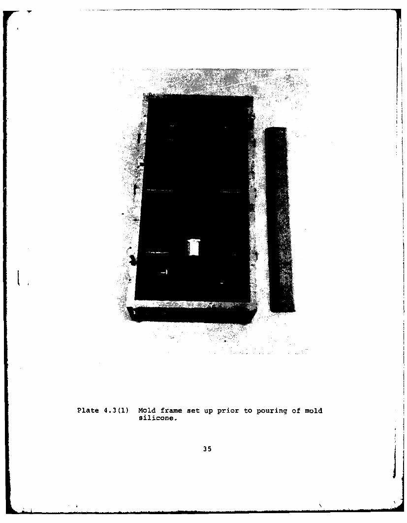
Plate 4.3(1) Mold frame set up prior to pouring ofmold silicone ....... ................... .. 35
Plate 4.3(2) Inlet guide vane after demolding . . . . 36
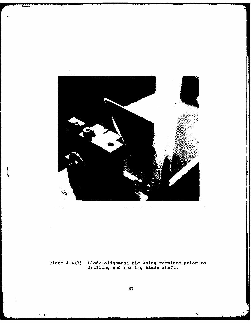
Plate 4.4(1) Blade alignment rig using templateprior to drilling and reaming blade shaft ..... 37
Plate 4.4(2) Grinding rig for finishing blade tips . . 38
.v
1. INTRODUCTION
Tip clearance has long been known to be a source of losses
in axial compressors with cantilevered blades. The reasons for
the losses, however, are not well understood and current prac-
tice in engine design still requires extensive effort to main-
tain constant minimal operating clearances over a wide range of
conditions. The emphasis on clearance control may be appre-
ciated by the typical observation that a ten percent change in
peak static pressure rise in a compressor stage may occur for a
fifty percent change in clearance. Clearances are typically in
the one to five percent of major passage dimension range, and
thus a small change in passage dimensions represents a large
change in clearance.
It is clear that, in general, it would be desirable that
blading performance be less sensitive to changes in clearance.
Less sensitivity would allow a general relaxation of the mech-
anical tolerances on a compressor assembly and provide more
consistent transient performance. The aerodynamics of achieving
such a situation are a challenge as the underlying requirement
is improved performance at larger clearances.
Work toward understanding the basic mechanisms of tip
clearance effects with an emphasis on designing for clearance
has been commenced at the Naval Postgraduate School Turbopro-
pulsion Laboratory (NPS/TPL). This report summarizes the pre-
liminary work on the Multistage Compressor (MSC) facility at
the Laboratory.

The basic approach to designing for tip clearance differs
from previous studies in that the main emphasis lies on measure-
ment of the secondary flow rather than the tip gap flow and the
flow field is considered across the whole span rather than near
the tips. The approach is summarized in the design problem
statement below.
1.1 Design Problem Statement
Given basic annular dimensions, mass flow, rotational speed
and desired pressure rise; design a blading which will achieve
the desired stage performance with the lowest sensitivity to
gap at the blade tip. The process usually consists of an air
angle design to establish blade class and a blade design to
determine the type, followed by a performance analysis to deter-
mine the efficiency. To complete the procedure the designer
is required to make certain assumptions; in particular, the
degree of reaction, the axial velocity radial gradient or the
whirl velocity gradient. How these assumptions interact with
or are related to tip clearance sensitivity is not clear.
From a primary flow analysis for a two-dimensional flow
it is possible to calculate the primary velocity-angle field.
The tip clearance effects are closely related to the secondary
flow field, thus in order to approach the design problem it is
necessary to examine the secondary flow field. This can only
be done by experiment. The modifications in primary flow field
due to the secondary can be measured with suitable instrumenta-
tion. Complete velocity, angle and pressure surveys of the flow
field can be related to the forces on the blade and thus to the
2
design of the blade type and ultimately to the performance.
By incorporating the tip gap as an experimental parameter the
sensitivity factor may be explored.
3
I kw
2. REVIEW OF PAST APPROACHES
TO TIP CLEARANCE EFFECTS
From the design problem statement it is apparent that the
nature of losses incurred in the tip region are reflected in
the pressure distribution on the blade near the tip. Whether
a model of the flow field is formulated in terms of vortex
field, through flow defect or velocity angle fields, a basic
integration requires the losses to be represented in the equi-
librium pressure field for the stage. The gradients of this
field provide a framework to review past work on tip clearance
effects.
2.1 Approaches Using Machine Relative Pressure Gradients
The machine relative gradients are defined in the absolute
coordinate frame and comprise axial, radial and peripheral
gradients. Axial gradients are generally developed due to
diffusion in the blade row and early (Fickert) estimates of
losses due to clearance were based on the flow in the annular
area created by a tip gap not being subjected to blade guidance,
and hence a loss in recovery. Peripheral gradients are created
due to flow turning in the blade row creating a pressure gra-
dient from one side of a passage to the other, and hence a pres-
sure and suction side on the blade. Several methods (Rains, Wu
and Wu) of loss estimation are based on the proposition that
flow in a tip gap due to this gradient creates a momentum which
is lost due to vortex dissipation. Radial gradients are developed
4
in rotating rows due to the centripetal and coriolis forces
on fluid elements. Some attempts have been made (Vavra, Smith)
to develop loss descriptions on the basis of radial gradients
of whirl velocity.
Characteristics of these approaches are the assumption
of a loss due to tip leakage and an orientation toward rotating
machine tests.
2.2 Approaches Using Blade Relative Pressure Gradients
Considerable testing of tip flow effects has been con-
ducted in two dimensional cascades using pressure gradients
that could be considered blade relative. The basic gradients
are chordwise, pitchwise and spanwise. Studies on chordwise
gradients in the form of circulation near blade tips (Laksh-
minarayana) and vortex shedding suggest there is an optimal
clearance where the tip flow vortex will balance and cancel
other vortex formations. Pitchwise gradients studied with
moving belt walls in cascades (Dean, Gearhart) have a similar
tendency to conclude that tip flows may sweep low energy flow
away from the blade suction surface and improve blade guidance
of high energy fluid. Spanwise gradients on blades are less
related to tip flow; however, on a mixing basis (Thompkins)
they may contribute a significant loss at a blade tip due to
a small crossflow on the blade surface.
Blade relative approaches tend to conclude some tip leak-
age is beneficial in contrast to the "defined-loss" approach
of Sub-Section 2.1.
5
2.3 Comparison of the Co-Ordinate Systems
The major differences between the systems are the rotation
of the blade relative frames in actual machines, the typical
twist on blades in rotating frames and the radial variation in
passage cross section. Measurements of velocity fields down-
stream of rotors in the rotor relative frame (Dring) do not
necessarily show the clear vortex formations of the cascades
with untwisted blades. The flow may appear as a vortex in the
absolute frame, or a spiral.
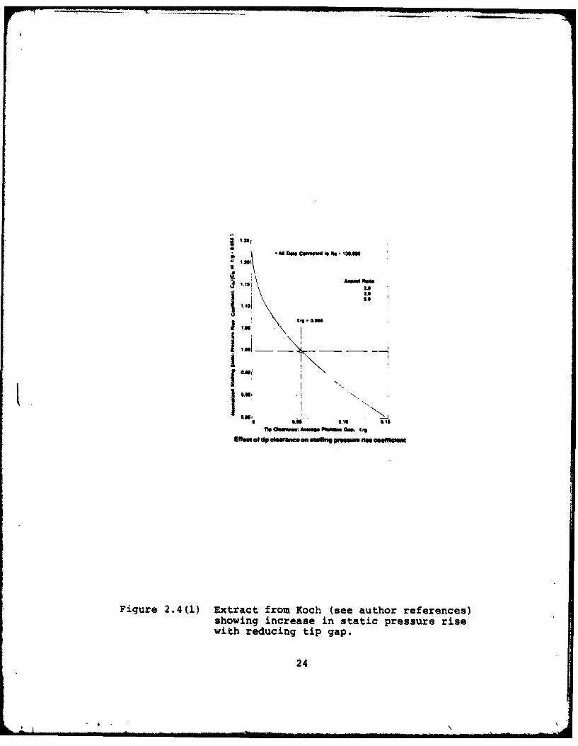
2.4 Correlations of Tip Clearance on Machine Stages
Often tip clearance effects are presented in an empirical
fashion for a particular machine under test. Typical results
show changes in efficiency, peak pressure rise or similar de-
pendent variables as a function of tip gap. These results
usually show an increasing performance with reducing gap, Fig-
ure 2.4(1) and significant improvements as the gap is reduced,
Figure 2.4(2), in stall or other characteristics.
These results usually show for a practical mechanical
range of clearance the minimum gap achieves the best perfor-
mance. There are some claims that clearance losses alter with
loading or flow co-efficient but are not strongly substantiated.
2.5 Summary
Empirical evidence supports the "defined-loss" approaches
over the cascade flow models, however in both approaches there
is a strong tendancy to focus on the gap flow as the primary
loss mechanism. It is not entirely clear that this is the case
6
and there are reasonable grounds to suspect the losses may
occur for other reasons and that the tip flow augments these
processes.
7
3. CURRENT APPROACH TO TIP CLEARANCE EFFECTS
The approach to tip flow effects described in Section 2
has been formulated with a strong emphasis on local flow near
or in the tip gap. The major exception being work (Smith) at
General Electric where aspect ratio has been a dominant para-
meter of study. Very little information can be found on the
influence of blade class correlation to secondary losses in
the blading. This aspect of the secondary flow problem is
fundamental to the NPS/TPL program. The following sub-sections
develop, briefly, the approach in the context of the NPS/TPL
Multi-Stage Compressor Facility.
Tip clearance flows become only one part of a more complex
flow field in such an approach; however, the tip gap has been
selected as a study variable because it has practical signifi-
cance in attaining peak performance from a compressor stage
(Figure 2.4(t)).
3.1 Influence of Blade Class on Primary Flow
Blade class is defined as the velocity and angle field
selected for a blading; for example, free vortex blading has a
particular velocity and flow angle distribution. Blade type
refers to the particular aerodynamic profile selected; for
example, circular arc or NACA-65 sections. With certain assump-
tions about the flow field it is possible to investigate the
primary flow of a large number of blade classes by varying the
peripheral velocity distribution across the span ahead of the
rotor with a parametric equation of the form
8
R RV A-+B+C-- 3.1(1)u R Rm
and from considerations of radial equilibrium and enthalpy:
dho0 V dV a V dV u V u2R= a + u a + R 3.1(2)
Selections of A, B, C and assumptions of enthalpy and
axial velocity gradients result in a variety of blade classes.
For example, selection of dh/dR = dV a/dR = 0 and B = C = 0
results in a free vortex blading. A variety of blade classes
have been examined in Ref 3.1(1) with and without enthalpy
gradients for various degrees of reaction. Enthalpy gradients
were found to have a significant effect on the velocity, angle
field. Figures 3.1(1) and 3.1(2) show the differences in
axial velocity before and after the rotor for a selection of
classes. The velocities differ considerably near the rotor
tip and are expected to show different secondary flow charac-
teristics.
3.2 Measurement of Secondary Flow by Blade Class/Type
Secondary flow in compressor blading is generally attri-
buted to the effect of a fluid with a radially varying axial
velocity being subjected to turning by the blades in a radial-
peripheral plane (Figure 3.2(1)). The axial velocity distri-
butions in Figure 3.1(1) show significant differences by blade
class. Thus the differences in secondary flow produced by these
blades are of some interest as, typically, the losses in a blading
9

are most pronounced where the secondary flow effects are strong-
est. Tip clearance is known to alter the loss position in a
passage.
Measurement of these flows may be accomplished in the
laboratory frame of reference with synchronized high response
instrumentation for rotating blades. Provided the blade pas-
sage dimensions are large compared to the sampling probes,
reasonably accurate measurements of the unsteady flow field may
be made. A major element of the NPS/TPL approach to tip flow
and clearance effects is measurement of these flow fields by
blade class for the full blade passage.
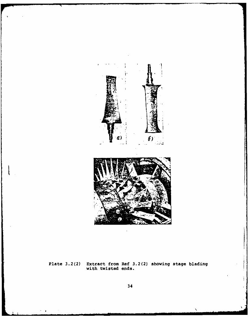
It should also be noted that the blade type for a given
class is of significance. While the blade class specifies the
basic angles and velocities to be obtained, the thickness dis-
tribution, solidity, aspect ratio and so on are not defined.
A wide range of types can be developed. For example, Plate
3.2(2) shows blading for an existing stage at NPS/TPL designed
in Ref 3.2(2) to the free vortex class. The secondary flow of
this type of blading is of great interest as the tips have been
designed to reduce the level of secondary losses.
3.3 The Multistage Compressor Facility
To obtain reasonable accuracy in secondary flow measure-
ments it is desirable that the test device:
(a) Be of large scale to facilitate measurements;
(b) Obtain Reynolds Numbers in a typical compressor
operating range;
10
(c) have blading with a representative range of diffusion
factors;
(d) Generate the incoming boundary layers of a repeating
stage with upstream stages;
(e) Be operational with low inlet turbulence and distor-
tion.
The NPS/TPL multistage compressor facility described in Ref
3.3(l) meets most of these basic requirements. The repeating
stage requirement may not be completely satisfied with two
upstream stages.
Although it might be desirable to conduct tests on blading
with higher hub-to-tip ratios (0.8) and solidities (1.5) to be
more representative of high through-flow compressor blading,
there are experimental advantages to first examining the char-
acter of the secondary flow in the MSC range (hub-to-tip 0.6,
solidity 1.0). In this range of parameters there are clearly
two tip regions of reasonable scale on the span, while on the
higher hub-to-tip ratio bladings the regions tend to merge.
In terms of future work, hub-to-tip and solidity modifications
are possible on the compressor annulus to achieve the range
outlined; however, for the immediate goals the facility is
considered to be adequate.
3.4 Facility Parameter Variations
The multistage compressor is basically a fixed solidity,
variable stagger installation. Stationary blade stagger may
be altered without disassembly of the compressor case. Para-
meter variations may be accomplished in following order of com-
plexity:

(a) Flow rate
(b) Blade stagger (stationary)
(c) Speed (may require inlet change)
(d) Blade stagger (rotor)
(e) Number of stages
(f) Blading
From the order above, it is clear that testing must be com-
pleted by blade class. Thus an experimental program developed
on one blading must be suited to all blading developed to avoid
rebuilding the machine several times with the same blades.
Introducing tip gap variations complicates the parameter
order. The approach adopted to date is to operate the blading
at sucessively larger clearances from safe minimum. This re-
quires grinding off the blade tips, and is thus equivalent to
step (f) above - reblading. Altering the clearance by building
up the blade tips is equivalent to step (d); however, the use
of tape or some other adhesive technique is not as dimensionally
precise as grinding. A compromise may need to be struck in
this area as 9 to 12 rebuilds may be required for each blading
at different clearances. The possibility of eccentric opera-
tion of the rotor has not been considered to date.
3.5 The Experimental Approach
The approach adopted for the program has been to measure
the secondary flow field at design and at peak pressure rise
in a multistage configuration for the following parametric
changes:
12
A%

(a) Blade class
(b) Tip gap
(c) Inlet boundary layer
In addition, as each stage is added to the machine a survey of
the flow field development in the stages would be recorded.
Using a symmetric stage as a reference case, comparisons
of stage efficiency and pressure rise would be developed in
addition to the flow field surveys. Analytical work is en-
visioned in parallel to the experimental program to attempt to
correlate the tip flow field with the calculated flow fields
described in Sub-Section 3.1
The main goal of the flow field measurement is to determine
the influence of the tip gap on the secondary flow field gen-
erated by the blade class, particularly in the position and
strength of the typical vortex formed near the hub and tip.
The position and strength of the vortex are known to influence
the deviation angle at the blade exit and hence the incidence
for the following row.
Work completed in preparing for such a program is described
in Section 4, and from this work a specific proposal following
the approach above has been prepared.
13
4. WORK COMPLETED AND RESULTS TO DATE
Activity directed at preparing the Multi-Stage Compressor
facility at NPS/TPL for testing along the lines discussed in
Section 3 was commenced in April 1980 and has been continued
through to August 1981. The work has been on a broad front
covering preliminary elements of a program.
Each of the areas summarized is described in detail in
a NPS/TPL technical note. The aggregate of the notes forms
a working body of inform;tion for investigators operating the
facility.
4.1 Survey of Literature on Tip Clearance and Tip Flows
A survey i literature related to tip clearance and asso-
ciated secondary flows was conducted. The survey is viewed as
ongoing as there has been significant effort recently on wake
flows near blade tips. The survey, Ref 4.1(1), revealed dis-
tinct periods of investigation of tip effects and a slowly
growing concensus on the nature of tip flows over a period of
forty years.
The literature shows two distinct schools of thought.
Investigations of flow near blade tips in two-dimensional cas-
cades tend to show that a tip leakage flow is beneficial. The
location of low energy fluid in the cascade due to wall bound-
ary layers may be moved away from blade surfaces and generally
improve the effective fluid angle control by the blade. Work
in rotating multistage test machines tends to indicate the
14
smaller the tip leakage flow the higher the stage performance.
These results are not necessarily contradictory as the pressure
fields and circulation of the fluid in the test devices are
different. it is clear from the literature that the under-
standing of the effect of the interaction of tip gap, wall
boundary layers and secondary flow would be improved by knowl-
edge of the effect of air angle design on secondary flow and by
subsequent shaping of the blade to achieve the desired angles.
The papers reviewed also show that a general correlation
of blade geometry with secondary flow would be desirable.
There are many empirical rules of correlation at present,
mainly based on cascade work, which could be profitably uni-
fied for multistage rotating machines.
4.2 Blade Aero-Mechanical Design
In an effort to establish the deflected geometry of the
symmetric blading when operating and to allow for centrifugal
extension effects on tip clearance, stress and deflection
analyses on the blading were conducted. Analysis of a thin
twisted cantilever with a non-uniform load distribution is not
handled well by the plane strain techniques of simple beam
theory; however, this approach was adopted due to comparative
complexity of finite element techniques.
The deflections estimated have been found to be approxi-
mately in agreement with static load tests on isolated blades
and have been used for design purposes. The main tasks com-
pleted are documented in Ref 4.2(1) and set out as follows:
15

(a) Calculation of safe minimum running clearance for
epoxy blades;
(b) Calculation of design point loads and estimation
of deflections (bending and force equilibrium methods);
(c) Unsteady load estimates for starting and stalling;
(d) Material testing for creep, low and high cycle fatigue
and the basic stress-strain characteristics; reso-
nance measurements were also conducted;
(e) Measurement of the compressor annulus and compilation
of assembly tolerances;
(f) Review of the stress of root reinforcements and a
general analysis of stiffness of composites.
These analyses have indicated the symmetric blading meets the
basic operating loads but with a small safety margin at the
maximum speed condition. It is questionable whether the blading
j can be stalled at 2290 rpm safely (Figure 4.2(1)).
Initial work has been conducted on safety margins that
could be achieved with glass cloth or graphite reinforcement.
The results indicate much higher safety margins can be achieved
and aero elastic deflections will be much smaller. A general
design approach has been developed in Ref 4.2(1) for future
use. The approach incorporates plastic design methods.
4.3 Epoxy Blade and Blade Mold Fabrication
An important component of the tip clearance approach out-
lined in Section 3 is an ability to produce compressor blading
repeatably to various aerodynamic shape requirements. The
16
l I
tolerance on the blading may be of the order of ±0.005 inches
to achieve good percentage control on thin aerodynamic sections.
Blading of the symmetric type achieved these standards when
fabricated in the Laboratory in 1970. Because of the deteriora-
tion of molds with use at that time it was necessary to repro-
duce molds and blades to replace blades lost due to failure
in 1980. A sub-task of the program in 1981 was devoted to pro-
duction of molds for IGV blades and subsequent casting of a
vane row. Details of the task are presented in Ref 4.3(1).
Blading of a reasonable quality was produced; however,
the 1970 blading was dimensionally superior. Working through
the casting process indicated the following to be significant
(Plates 4.3(1) and 4.3(2) outline the casting methods):
(a) Master blades must be rigid and faired to avoid
undercuts in subsequent molds;
(b) The mold material must be flexible but have negli-
gible shrinkage;
(c) The molds must be carefully designed for even minute
shrinkage factors to maintain percentage control on
aerodynamic sections;
(d) Mold to blade material compatibility is critical,
especially in terms of quality of release;
(e) The work requires a high level of craftsmanship with
the major effort being directed to achieving a stable
durable mold of exact dimensional quality.
Based on this work, it was expected that further cycles of mold A
and blade fabrication would achieve a high quality of blading.
17
. . . .. . . . ... . . . .. . - I .. . ... . .
Within the limits of Section 4.2 the experience gained
indicated that blading could be produced in the Laboratory for
low cost with sufficient manpower and reasonable lead times.
Thus the projected blading fabrication for tip clearance
studies was technically feasible given sufficient resources
and the blades lost through failure could be recovered.
4.4 Blade Finishing and Installation
The process of completing a blade from a rough casting
has been developed and tooling fabricated to reduce the manual
effort and maintain the accuracy required for blade positioning
in the compressor case. Hand work is still required on the
leading and trailing edges of the blades due to flashing on
the casting. Reference 4.4(1) describes the finishing and in-
stallation details, the clearances selected, stress analyses
conducted and general blade condition information prior to the
first compressor build in July 1980. Subsequent work reported
in Ref 4.3(1) using more flexible molds has improved the filling
and release of the root section of the blade reducing the hand
work required.
Inspection of the compressor prior to the September 1980
runs led to the conclusion that a high degree of blade to blade
uniformity had been achieved in all the rows installed. Work
in July 1981 on the IGV row forced re-rexamining of existing
alignment holes in the vernier plates and combined with the
thickness variations encountered with casting has led to a
degradation of uniformity in that row.
18
The major tooling items developed include a blade align-
ment rig for drilling and pinning the stagger angle adjustment
plate to the blade. The rig is a copy of the blade mounting
on the compressor case walls with a provision to orient the
blade to the compressor axis with a template. The other major
item was a grinding table which may be adjusted to simulate any
compressor wall radius at the rig's cutting drum edge. Blade
tip contours may be cut at any blade stagger set up by the pin-
ning rig. Both of these devices may be used for any radially
stacked blades with modified templates. Minor modifications to
the rigs may be required if a different root system were to be
developed. Plates 4.4(1) and (2) show general features of the
rigs and, to date, a complete set of symmetric blading has been
finished and installed using the equipment.
4.5 Data Acquisition Systems
A basic data acquisition and storage/retrieval system has
been developed for the MSC facility using the HP9845/98034A
calculator and interface bus. This system is modular in nature
and has been designed to cover both steady static and transient
data measurements. The system software modules for steady
state data were completed in July 1980 and are documented in
Ref 4.5(1). A schematic layout of the steady state data acquisi-
tion system is shown in Figure 4.5(1) and the basic block dia-
gram of the software in Figure 4.5(2).
The system was used for baseline testing in September 1980
and the subsequent data analysis reported in Ref 4.7(1). Based
on this experience the data storage system will be modified to
19
improve flexibility. Preliminary design of a transient data
acquisition module for the program has been addressed. The
current experimental goal of this software is to establish
that the steady state data are, in fact, steady. Recording
of baseline data showed sufficient scatter to warrant a higher
frequency acquisition technique. Future instrumentation is
expected to require a high frequency sampling system.
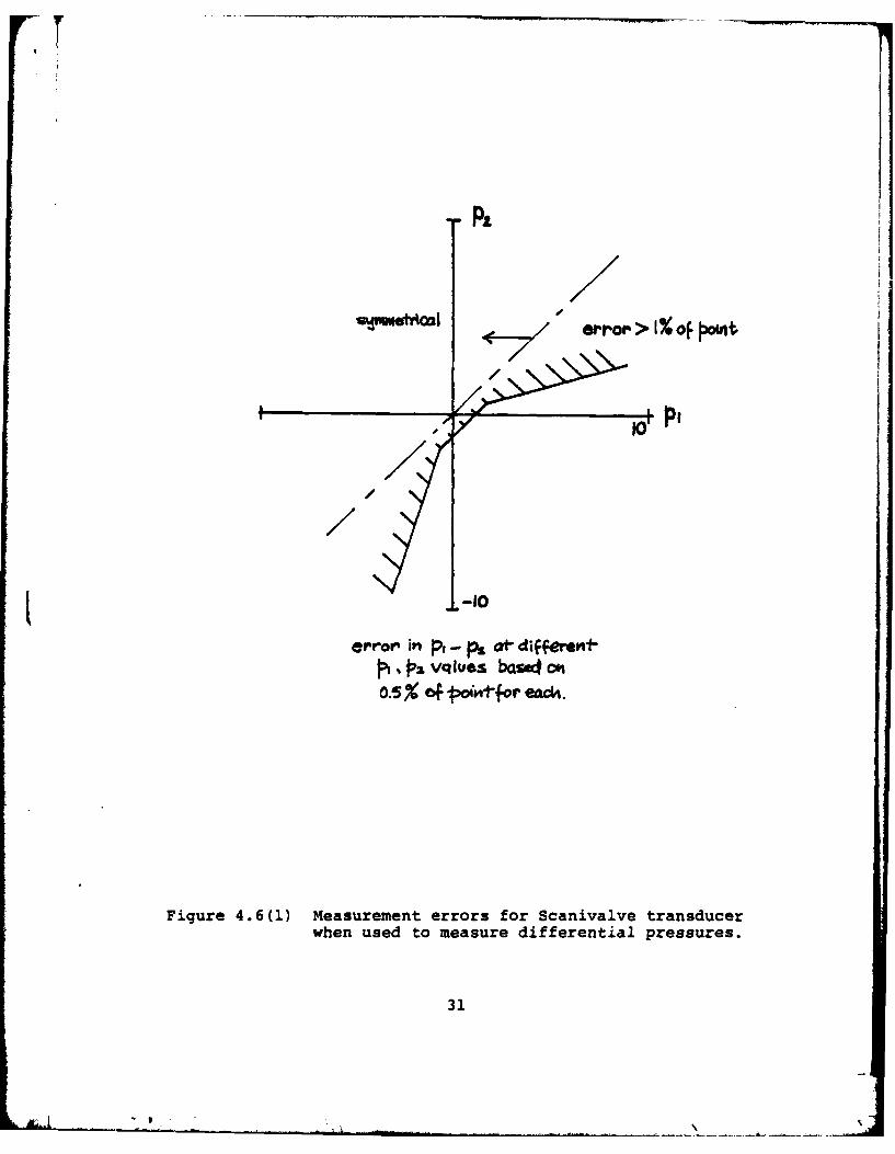
4.6 Probe and Instrumentation Development
Work to date on instrumentation has been directed at
standard pneumatic systems and obtaining accurate pressure
field measurements. The basic measurement system consists of
two Scanivalve transducers both calibrated in the 0 - 50 in.-
water range. Valve ports are allocated for tare and span
checks using an atmospheric reference pressure and a calibra-
L tion pressure on each transducer. Ambient pressure is moni-
tored with an absolute transducer. The system has been con-
figured to maximize system accuracy around atmospheric pressure
for differential pressures greater than 5 in.-wate;i For v
speed operation (1600 rpm), inlet nozzle differential pressure
falls below this range leading to the use of dedicated dif-
ferential transducers to improve resolution at low flow rates.
Figure 4.6(1) indicates the current accuracy envelope for the
pneumatic system.
Multi-hole survey probe calibrations required review for
use on the MSC. The pressure levels and velocities are low
for the 1600 rpm condition. Existing TPL calibration routines
were converted by H. Zebner to a matrix interpolation procedure
20
during 1980 and this technique was adopted to maximize low
speed measurement accuracy for multi-hole probes. Results
from baseline tests in September 1980 indicate the technique
may require further development to reach the desired accuracy.
A general review of time required for survey of stage
exit flow conditions, particularly for several boundary layer
thicknesses, suggested development of a circumferential survey
rake for use near the case wall. This rake was fabricated in
June 1980 and its construction is documented in Ref 4.6(1).
The probe is shown in Figure 4.6(2). Particular emphasis was
placed on obtaining wide pitch/yaw characteristics for the kiel
heads. The design used achieved ±500 when calibrated.
A basic complement of pneumatic probes is being built up
for the compressor and future work will be directed to higher
frequency response instrumentation.
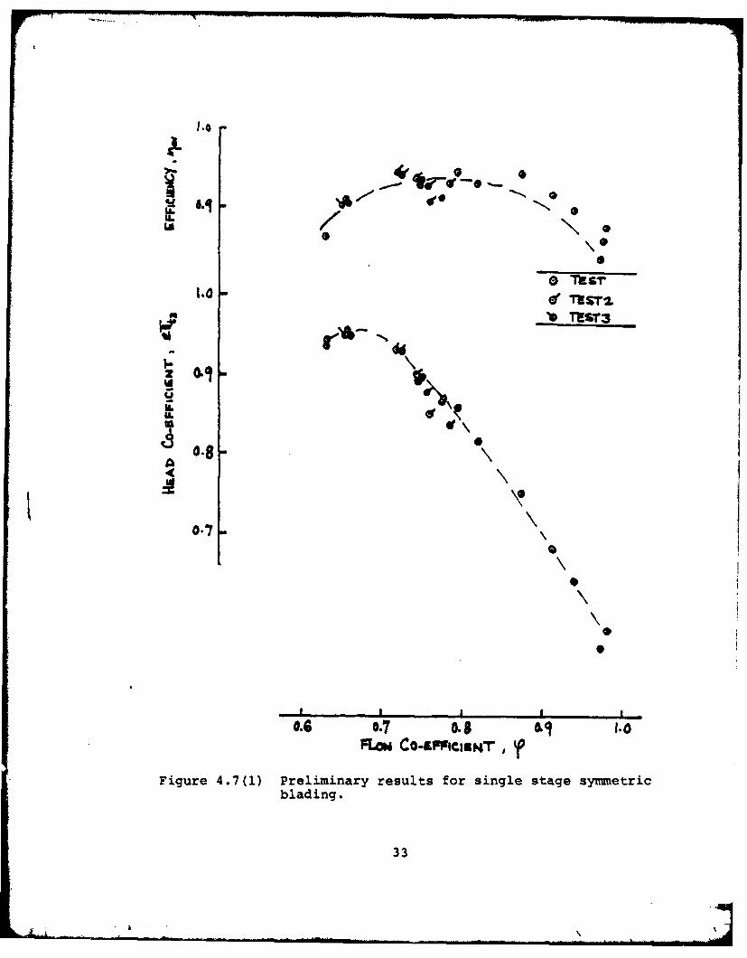
4.7 Baseline Testing
Compressor baseline testing for a single stage at 1600 rpm
was conducted in September . -80. The compressor blading failed
after six hours of operation. Nineteen data points were re-
corded over a range of flow rates from near stall to open throt-
tle. As the verification of the instrumentation and data system
was continuing while the data were collected the results were
considered preliminary. Generally the stage performance cor-
relates well with the design based on mean radius measurements.
The efficiency (total to total) for the stage agrees well with
predictions. Pressure co-efficient is higher than expected.
Overall the stage seems well-suited to the experimental tasks
21
outlined in Section 3 and, as the blading was operating with a
tip clearance of =0.3% of span, sufficiently small clearances
have been achieved to facilitate tip clearance variations in
a practical range of interest. The stage failure is thought
be be due to over-deflection of the rotor blades axially. There
was no indication of blade rub on the case walls.
The preliminary results are set out in Ref 4.7(1) and the
stage characteristic is shown in Figure 4.7(l). Testing in
August 1981 following the compressor rebuild has been concerned
with establishing the mechanical integrity and reliability of
the blading prior to re-instrumenting the compressor.
L
22
5. CONCLUSION
Progress in a proposed experimental program aimed
toward enabling the design of axial flow compressor blading
to include tip clearance effects has been presented.
A particular approach has been suggested which requires
the investigation of several blading designs in the 3-stage
axial compressor.
The arguments on which the approach is based have been
outlined and a classification and review of previous reported
studies has been given.
The work reported here was of a preparatory nature and
directed at providing the blading, instrumentation and methods
for measuring the flow field. The details of the work are
contained in a series of Technical Notes for which references
were given.
The immediate goals of the project are to show that:
i) Data of sufficient accuracy and repeatability can
be obtained from the compressor;
ii) The required blading can be generated at accep-
table cost.
These questions are considered key to obtaining defini-
tive results from the study.
23
i ,.'1
tl As Do ao CmfeeS 139.0
, l.11II .O4
I 1-, -HO.W OW o~ft
Tip aim... humsg PalmS. Oe. ig
Efftei tip earncee ta~n pteser tiesm c ,elefe
Figure 2.4(1) Extract from Koch (see author references)showing increase in static pressure risewith reducing tip gap.
24
.20
.V
.70
1.8 Nominal non .rolonq tipclearanc. /
cm /
1.6 0 a1061 , ecn
0 .140 / desigtspwd,178 .1
S. - Stall line
12 ?O-Percentdesln sped
a 12 16 20 24 21 32Equivalent airflow, kqlsc
Fiqure 8. - Effect of rOt-lae tip clearanc on Overall pr rtfrmcin ofstlaqe 8-8 with solid casinq.
Figure 2.4(2) Extract from Moore (see author references)showing influence of tip clearance on stalland efficiency for a transonic fan.
25
1,0
V 1
WR
Ported
.9__ _ _ _ _ _ _ __ _ _ _ _ _ _
.7
.6__ _ _ _ _ _ _ _ __ _ _ _ _ _ _ _ __ _ _ _ _ _ _ _
.75 .875 1.0 1.125 1.25
R/R M
Figure 3.1(1) Extract from Ref 3.1(1) showing axial velocitydistribution ahead of rotor for different bladeclasses.
26
V2
.8-
.61.75 .875 1.01.25 1 -2
R/RM
Figure 3.1(2) Extract from Ref 3.1(1) showing axial velocitydistribution after rotor for different bladeclasses.
27

k. -& W ,S 0 , i ,.
k:L1 --L f
|I k",K ~qke. oac..
28.
ib:asm.
eh-P-= ~ ~ ~ ~ 1k4 iMO4tf7M f bg'
Crr aK. e%;I C dyc
Figre .2() Sres leels a ld oo safucino
sped cmpaed ithmtra s ftrsss
280
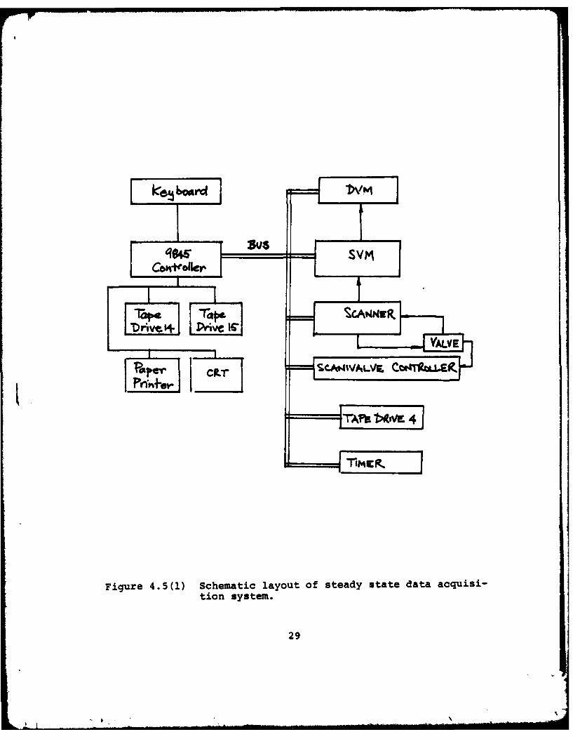
Figure 4.5(1) Schematic layout of steady state data acquisi-
tion system.
29
A . IUST ~k.
A iT~~d
Wite
Figure 4.5(2) Block diagram of data reduction software.
30
IJP,
Si-r > Iof Jaouui
Figure 4.6(l) Measurement errors for Scanivalve transducerwhen used to measure differential pressures.
31

Figure 4.6(2) Sketch of circumferential rake.
32
... "- ". .. ... .ilIIIl -" III111 .... ... ... . . .
• .... L "1
LAI
, TIS-
2 0.4
o.'l \'
'I
C\
IL
'A
0.8
0.77
\
\
S I I I,0.6 o.7 0.8 0! 9 1.0
FLi Co-AFFI4Ci, , PFigure 4.7(1) Preliminary results for single stage symmetric
blading.
33
r - - £ ~
.- : ~VVV
'~ at a.
pr ft
- I
- I
#1) 6)'I
it [
Plate 3.2(2) Extract from Ref 3.2(2) showing stage bladingwith twisted ends.
34
I
A U
Plat 4.(l)Mol frae st u pror t porin ofmolsilicone.~O'
35~
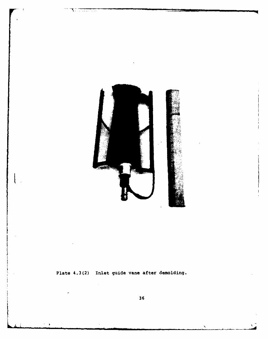
Plate 4.3(2) Inlet guide vane after demolding.
36
p I
377
Plate 4.4 (1) Blade alignment rig using template prior todrilling and reaming blade shaft.
37

Aligning Exit Guide VanesBefore Grinding
Grinding Set-Up
Plate 4.4(2) Grinding rig for finishing blade tips.
38
LIST OF AUTHOR REFERENCES
Dean, R. C., Jr., "The Influence of Tip Clearance on Boundary-Layer Flow in a Rectilinear Cascade," MIT, Gas TurbineLaboratory, Cambridge, Massachusetts, Report No. 27-3,December 1954.
Dring, R. P., Joslyn, H. D., Hardin, L. W., "Compressor RotorAerodynamics - An Analytical and Experimental Investiga-tion," United Technologies Research Center, UTRC 80-15,March 1980.
Fickert, "The Influence of the Radial Clearance of the Rotoron the Compressor Efficiency," Part C of "The Influenceof Physical Dimensions and Flow Conditions on CompressorCharacteristics," Bureau of Ships 338, 1946, pp. 95-108.
Gearhart, W. S., "Tip Clearance Flow in Turbomachines," Pen-nsylvania State University, Institute for Science andEngineering, Ordnance Research Laboratory, TechnicalMemorandum File No. TM 506.2491-04, August 27, 1964.
Koch, C. C., "Stalling Pressure Rise Capability of Axial FlowCompressor Stages," ASME Gas Turbine Conference, Houston,Texas, March 9-12, 1981, Paper No. ASME 81-GT-3, March 1981.
Lakshminarayana, B., "Methods of Predicting Tip ClearanceEffects in Axial Flow Machiner," Journal of Basic Engi-neering, ASME, September 1970, p. 467.
Rains, D. A., "Tip Clearance Flows in Axial Flow Compressorsand Pumps," California Institute of Technology, Mech. Eng.Lab. Report No. 5, June 1954.
Moore, R. D., Osborn, W. M., "Effects of Tip Clearance onOverall Performance of a Transonic Fan State with andwithout Casing Treatment," NASA TMX-3479, February 1977.
Smith, L. H., Jr., "Casing Boundary Layers in Multistage AxialFlow Compressors," Flow Research on Blading, L. S. Dsung,ed., Elsevier Publising, Amsterdam, Net erlands, 1970.
Thompkins, W. T., Jr., Usab, W. J., Jr., "A Quasi-Three-Dimensional Blade Surface Boundary Layer Analysis forRotating Blade Rows," ASME Gas Turbine Conference, Houston,Texas, March 9-12, 1981, Paper No. ASME 81-GT-126, March1981.
39
II
Vavra, M. H., Aero-Thermodynamics and Flow in Turboinachines,John Wiley and Sons, Inc., 1960. - -______
Wu, C. H., Wu, W., -Analysis of Tip Clearance Flow in Turbo-machines," Polytechnic Institute of Brooklyn, Gas TurbineLaboratory, Report NIo. 1, July 1954.
40
LIST OF REFERENCES
3.1(1) Schlachter, W. S., "Calculations for Axial CompressorBlading with Uniform Inlet Enthalpy and Radial EnthalpyGradient," Naval Postgraduate School, Monterey, Califor-nia, Report NPS67-81-008, May 1981.
3.2(2) Beknev, V. S., "Investigation of an Axial Flow Com-pressor Stage Designed with Due Regard for Losses withBlade Height," Thermal Engineering (USSR), January 1961.
3.3(1) Vavra, M. H., Pucci, P. F., Schlachter, W. S., "Re-design of the Low Speed Three Stage Axial Flow Compres-sor Facility," Naval Postgraduate School, Monterey,California, Report NPS-57Va73121A, December 1973.
4.1(1) Moyle, I. N., "Multistage Compressor - Survey of Lit-erature on Tip Clearance and Blade Tip Flow Effects inAxial Turbomachines," Naval Postgraduate School, Monterey,California, Technical Note TPL TN 81-01, September 1981.
4.2(1) Moyle, I. N., "Multistage Compressor - Blade Aero-mechanical Design," Naval Postgraduate School; Monterey,California, Technical Note TPL TN 81-02, September 1981.
4.3(1) Moyle, I. N., "Multistage Compressor - Fabrication ofMolds and Casting of Epoxy Blades," Naval PostgraduateSchool, Monterey, California, Technical Note TPL TN 81-03,September 1981.
I4.4(1) Moyle, I. N. and Zebner, H., "Multistage Compressor -Installation of Cast Epoxy Blades," Naval PostgraduateSchool, Monterey, California, Technical Note TPL TN 80-06,October 1980.
4.5(1) Moyle, I. N., "Multistage Compressor - Data AcquisitionSoftware," Naval Postgraduate School, Monterey, California,Technical Note TPL TN 80-07, October 1980.
4.6(1) Moyle, I. N., "Multistage Compressor - CircumferentialRake Design and Fabrication," Naval Postgraduate School,Monterey, California, Technical Note TPL TN 80-08, Octo-ber, 1980.
4.7(1) Moyle, I. N., "Multistage Compressor - Initial Measure-ments with One Stage of Symmetric Blading," Naval Post-graduate School, Monterey, California, Technical NoteTPL TN 80-09, October 1980.
41
A-A
DISTRIBUTION LIST
No. of Copies
1. Library 4Code 0212Naval Postgraduate SchoolMonterey, California 93940
2. Office of Research Administration 1Code 012ANaval Postgraduate SchoolMonterey, California 93940
3. I. Moyle 5Exotech Pty Ltd.Monterey Business CenterBox 3060Monterey, California 39340
4. Director, Turbopropulsion Laboratory 30Department of AeronauticsNaval Postgraduate SchoolMonterey, California 93940
5. Dr. A. D. WoodOffice of Naval Research Eastern/
Central Regional Office666 Summer StreetBoston, Massachusetts 02210
6. Dr. Gerhard Heiche 1Naval Air Systems CommandCode AIR-310Navy DepartmentWashington, D.C. 20360
7. Chief, Fan and Compressor Branch 1Mail Stop 5-9NASA Lewis Research Center2100 Brookpark RoadCleveland, Ohio 44135
42
- )