Embed Size (px)
Citation preview

Difficulty Leveleasy 1 2 3 4 5 difficult
Estimatedinstallation:1-2hours
Special Tools RequiredNone
rev121517
#C5652 Installation Instructions2014+ Chevy 1500Fender Trimming Kit
Read and understand all instructions and warnings prior to installation of product and operation of vehicle.ZoneOffroadProductsrecommendsthissystembeinstalledbyaprofessionaltechnician.Inadditiontotheseinstructions,profes-sionalknowledgeofdisassembly/reassemblyproceduresandpostinstallationchecksmustbeknown.Minimumtoolrequirementsincludethefollowing:Assortedmetricandstandardwrenches,hammer,hydraulicfloorjackandasetofjackstands.Seethe"SpecialToolsRequired"sectionforadditionaltoolsneededtocompletethisinstallationproperlyandsafely.
»Product Safety Warning
CertainZoneSuspensionProductsareintendedtoimproveoff-roadperformance.Modifyingyourvehicleforoff-roadusemayresultinthevehiclehandlingdifferentlythanafactoryequippedvehicle.Extremecaremustbeusedtopreventlossofcontrolorvehiclerollover.Failuretodriveyourmodifiedvehiclesafelymayresultinseriousinjuryordeath.ZoneOffroadProductsdoesnotrecom-mendthecombineduseofsuspensionlifts,bodylifts,orotherliftingdevices.
Youshouldneveroperateyourmodifiedvehicleundertheinfluenceofalcoholordrugs.Alwaysdriveyourmodifiedvehicleatre-ducedspeedstoensureyourabilitytocontrolyourvehicleunderalldrivingconditions.Alwayswearyourseatbelt.
»technical SuPPort
www.zoneoffroad.commayhaveadditionalinformationaboutthisproductincludingthelat-estinstructions,videos,photos,etc.
Sendane-mailtotech-zone@sporttruckusainc.comdetailingyourissueforaquickresponse.
888.998.ZONE CalltospeakdirectlywithZonetechsupport.
»Pre-inStallation noteS
1.Specialliteraturerequired:OEServiceManualformodel/yearofvehicle.Refertomanualforproperdisassembly/reassemblypro-ceduresofOEandrelatedcomponents.
2.Adheretorecommendationswhenreplacementfasteners,retainersandkeepersarecalledoutintheOEmanual.
3.Largerrimandtirecombinationsmayincreaseleverageonsuspension,steering,andrelatedcomponents.Whenselectingcombina-tionslargerthanOE,considertheadditionalstressyoucouldbeinducingontheOEandrelatedcomponents.
4.Postsuspensionsystemvehiclesmayexperiencedrivelinevibrations.Anglesmayrequiretuning,slideronshaftmayrequirere-placement,shaftsmayneedtobelengthenedortrued,andU-jointsmayneedtobereplaced.
5.SecureandproperlyblockvehiclepriortoinstallationofZoneOffroadProducts.Alwayswearsafetyglasseswhenusingpowertools.
6.Ifinstallationistobeperformedwithoutahoist,ZoneOffroadProductsrecommendsrearalterationsfirst.
7.Duetopayloadoptionsandinitialrideheightvariances,theamountofliftisabasefigure.Finalrideheightdimensionsmayvaryinaccordancetooriginalvehicleattitude.Alwaysmeasuretheattitudepriortobeginninginstallation.
»Zone Offroad Products • 491 W. Garfield Ave., Coldwater, MI 49036 • 888.998.ZONE • www.zoneoffroad.com

C5652Installation-pg.2
Trim Bracket Installation Instructions1. Parkvehicleonclean,flat,andlevelsurface.Thisinstallationcanbeperformed
withthetiresonthevehicleontheground.Thetireswillneedtobeturnedinordertogainaccesstoallofthescrews/bolts.
2. Removetheplasticsplashguard.(2screwsand2clipsChevroletModels)Figure 1A & B.Leavethe2clipsinthebodyatthistime.Figure 1C
This kit will gain ~ 5/8" of clearance at the location noted with the arrow in Figure 1A. If additional clearance is needed at a different location addtional trimming may be required that is not outlined in these instructions.
Figure 1A
Figure 1B
Step 2 NoteThesplashguardcanberemovedbypullingittowardsthebackofthevehcilesandthenpullingstraightawayfromthevehicle.Thereare2clipsthatlockintothesplashguardandsnapintothebody.
Theplasticsplashguardalsohooksaroundthebottomsideofthebodypaneltoholditinplace.
Kit ContentsQty Part
1 DriverSideFenderTrimBracket1 PassengerSideFenderTrimBracket

C5652Installation-pg.3
Figure 1C
3. Removeallthescrewsholdingintheinnerfender(18screwsforChevroletmodels)Figure 2.Removetheinnerfenderfromthevehicle.
Figure 2
4. Pushthefenderinsulationupawayfromthebottomontherearfender.
5. Usingtheholeintheinnerfenderasareference,drawaverticallinedowntangenttotheouteredgeFigure 3.Drawahorizontallinetangenttothetopofthecircle.
Figure 3
Step 5 NoteItiseasiesttouseagrinderwithacutoffwheeltomakethecutsonthefender

C5652Installation-pg.4
6. Drawalinefromthebottomoftheverticaledgetoapproximately3/4"infrontofthebottomboltonthefender.Figure 4A & B
Figure 4A
3/4"
Figure 4B
7. Carefullycutalongthelinesmadeinthepreviousstep.Removethecutoutinnerfenderfromthevehicleandsetaside.Thescrewclipswillbeusedinthenewtrimbracket.
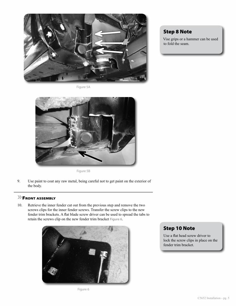
8. Cut3slicesalongthepinchweldseamandusingvicegripsorahammer,carefullyfoldtheseamtowardstheinsideofthetruckFigure 5A.TheformedjointshouldnowbeflatwiththebodyFigure 5B.ThebottomtriangleportionwillneedtobecutoffinordertofoldovertheseamasshowninFigure5B.
Step 8 NoteDoNOTcutapinchweld.Theseareidentifiedassmall3/8"circlesattachingthemetalflangestogether.
Step 8 NoteVisegripsorahammercanbeusedtofoldtheseam.
C5652Installation-pg.5
6. Drawalinefromthebottomoftheverticaledgetoapproximately3/4"infrontofthebottomboltonthefender.Figure 4A & B
Figure 4A
3/4"
Figure 4B
7. Carefullycutalongthelinesmadeinthepreviousstep.Removethecutoutinnerfenderfromthevehicleandsetaside.Thescrewclipswillbeusedinthenewtrimbracket.
8. Cut3slicesalongthepinchweldseamandusingvicegripsorahammer,carefullyfoldtheseamtowardstheinsideofthetruckFigure 5A.TheformedjointshouldnowbeflatwiththebodyFigure 5B.ThebottomtriangleportionwillneedtobecutoffinordertofoldovertheseamasshowninFigure5B.
Step 8 NoteDoNOTcutapinchweld.Theseareidentifiedassmall3/8"circlesattachingthemetalflangestogether.
Step 8 NoteVisegripsorahammercanbeusedtofoldtheseam.
Figure 5A
Figure 5B
9. Usepainttocoatanyrawmetal,beingcarefulnottogetpaintontheexteriorofthebody.
»front aSSembly
10. Retrievetheinnerfendercutoutfromthepreviousstepandremovethetwoscrewsclipsfortheinnerfenderscrews.Transferthescrewclipstothenewfendertrimbrackets.AflatbladescrewdrivercanbeusedtospreadthetabstoretainthescrewscliponthenewfendertrimbracketFigure 6.
Figure 6
Step 10 NoteUseaflatheadscrewdrivertolockthescrewclipsinplaceonthefendertrimbracket.

C5652Installation-pg.6
11. RemovethebottomboltonthefenderandinstallthenewfendertrimbracketstothevehicleattachingitwiththebottomboltFigure 7.Positionthebracketsothatitanglestowardstheouttercutedgeandtightenthebolt.Theuppercornerofthebracketwilltuckinbehindtheuntrimmedpartofthefender.Makesurethescrewclipisshowingandnottuckedbehindtheinnerfender.Ifthescrewclipishidden,additionaltrimmingmayberequired.
Figure 7
12. Reinstalltheinnerfenderwiththefactoryscrews.
13. Reinstalltheplasticsplashguard.Thetwoscrewsforthesplashguardwillgointotheclipsonthefendertrimbracket.Makesuretheplasticclipsareproperlyinstalledintotheplasticsplashguard.Theywillsnapintoplaceasshownin Figure 8A. Thefinishedfendertrimkitwillcompletelycoverthefendertrimbracket.Figure 8B
Figure 8A
Step 11 NoteInstallthefendertrimbracketsothatitissandwichedbetweenthefactorysheetmetallayers.
Step 13 NoteThetwoclipscanberemovedfromthebodybycompressingeachsideofthecliptoreleaseitfromthebodypanel.Twosmallscrewdriverstopusheachsideoftheclipinwillal-lowittoreleasefromthebodypanel.
Theclipswilllockintotheplasticsplashguard.

C5652Installation-pg.7
Figure 8B
Figure 8C
Figure 8D
14. Recheckhardwareafter500miles.
»front fender liner / Valence trimming
15. Thefrontofthefenderlinercanbetrimmedupusingaknifetogainadditionalclearance.Besuretotrimbelowthetwofenderscrewstokeepthefenderheldupsoitwillnotfalldown.

C5652Installation-pg.8
Figure 9
16. Thefrontvalancecanbetrimmedasneededtofollowthebodylineofthefrontbumperalongwithprovidingclearanceforthetire.
Figure 10
Post Installation17. Perfromasteeringsweeptocheckclearanceofthefrontfenderlinerandvalence
totrimmoreasneeded.
1. Checkallhardwareforpropertorque.
2. Checkhardwareafter500miles.
3. Adjustheadlightsiflargertireswereinstalled.
Post-Installation Warnings1. Checkallfastenersforpropertorque.Checktoensureforadequateclearancebetweenallrotating,mobile,fixed,andheatedmembers.Verifyclearancebetweenexhaustandbrakelines,fuellines,fueltank,floorboardsandwiringharness.Checksteeringgearforclearance.Testandinspectbrakesystem.
2. Performsteeringsweeptoensurefrontbrakehoseshaveadequateslackanddonotcontactanyrotating,mobileorheatedmembers.Inspectrearbrakehosesatfullextensionforadequateslack.Failuretoperformhosecheck/re-placementmayresultincomponentfailure.Longerreplacementhoses,ifneededcanbepurchasedfromalocalpartssupplier.
3. Performheadlightcheckandadjustment.
4. Re-torqueallfastenersafter100miles.Alwaysinspectfastenersandcomponentsduringroutineservicing.


