Embed Size (px)
DESCRIPTION
*C*
Citation preview

7/17/2019 *C*
http://slidepdf.com/reader/full/c563dba25550346aa9aa31d10 1/11
Casing Drilling: An Emerging TechnologyS.F. Shepard, SPE, and R.H. Reiley, SPE, BP America Production Co., and T.M. Warren, SPE, Tesco Corp.
Summary
BP America Production Co. used the Tesco Casing Drilling™*process to drill the surface and production intervals of 15 Wyo-ming gas wells. These wells range in depth from 8,300 to 9,600 ft.This paper provides a case-history discussion of the critical issuesencountered and resolved during the planning and operationsphases of this project.
Oilfield casing was used as the drillstring, along with a wire-line-retrievable bottomhole assembly (BHA), to reduce the overalltime required to drill, run casing, and cement the surface holes.Drilling with casing matched the rate of penetration (ROP) forconventional wells, and both the downhole and surface toolsproved to be reliable.
The production-hole interval turned out to be more challenging.Drillstring vibrations were encountered when drilling with the 41 ⁄ 2-in. casing, and difficulty was experienced in maintaining a com-petitive ROP with the wireline-retrievable drilling assembly. Thelast 11 production holes were drilled with casing and a nonretriev-able bit assembly. Nine of these wells were completed withouttripping the casing. Drilling times were competitive with conven-tional drilling in the Wamsutter area. One of the wells was the
third-fastest well ever drilled in the field.The project demonstrated that the casing-drilling process can
be used successfully but may not be cost-effective in all situations.It is probably better suited to softer formations and larger casingsizes than those used at Wamsutter. The process seemed to im-prove wellbore stability, reduce lost circulation, and minimize gasinflux, even when drilling with a lower mud weight than is typicalfor conventional drilling.
Introduction
Casing drilling, an innovative process for simultaneously drillingand casing a well, is emerging as viable technology for the 21stcentury. The concept builds on experience gained from drillingliners to the bottom in troublesome holes. With the advent of depend-able top-drive systems, wireline-retrievable BHAs, PDC bits, and
high-torque casing connections, it is possible to simultaneouslydrill and case a complete well with the casing as the drillstring.BP and Tesco undertook a project to drill five gas wells in the
Wamsutter area of Wyoming with the casing-drilling process. Thecasing-drilling program was initiated specifically as a joint tech-nology-evaluation projectbetween an operating and service company.A multiwell program was approved, because experience shows itoften takes several trials to successfully implement a new technology.Tesco provided the casing-drilling services as well as the rig forthe project under an incentive contract. Casing drilling proved sosuccessful that an additional 10 wells were added to the program.
Casing-Drilling Project Description
Casing-Drilling System Overview. The Tesco Casing Drillingsystem simultaneously drills and cases a well with normal oilfieldcasing as the drillstring.1 The casing transfers hydraulic and me-
chanical energy to a wireline-retrievable drilling assembly sus-pended in a profile nipple located near the bottom of the casing.
A drill lock (DLA) in the top of the drilling assembly providesmechanical (axial and torsional) coupling and hydraulic seals to
the casing. It also provides a mechanism to facilitate insertion and
retrieval from the casing string. The drilling assembly below the
DLA terminates in a pilot bit but may include other conventional
drillstring components, such as an underreamer, a mud motor,
coring, or a directional assembly.
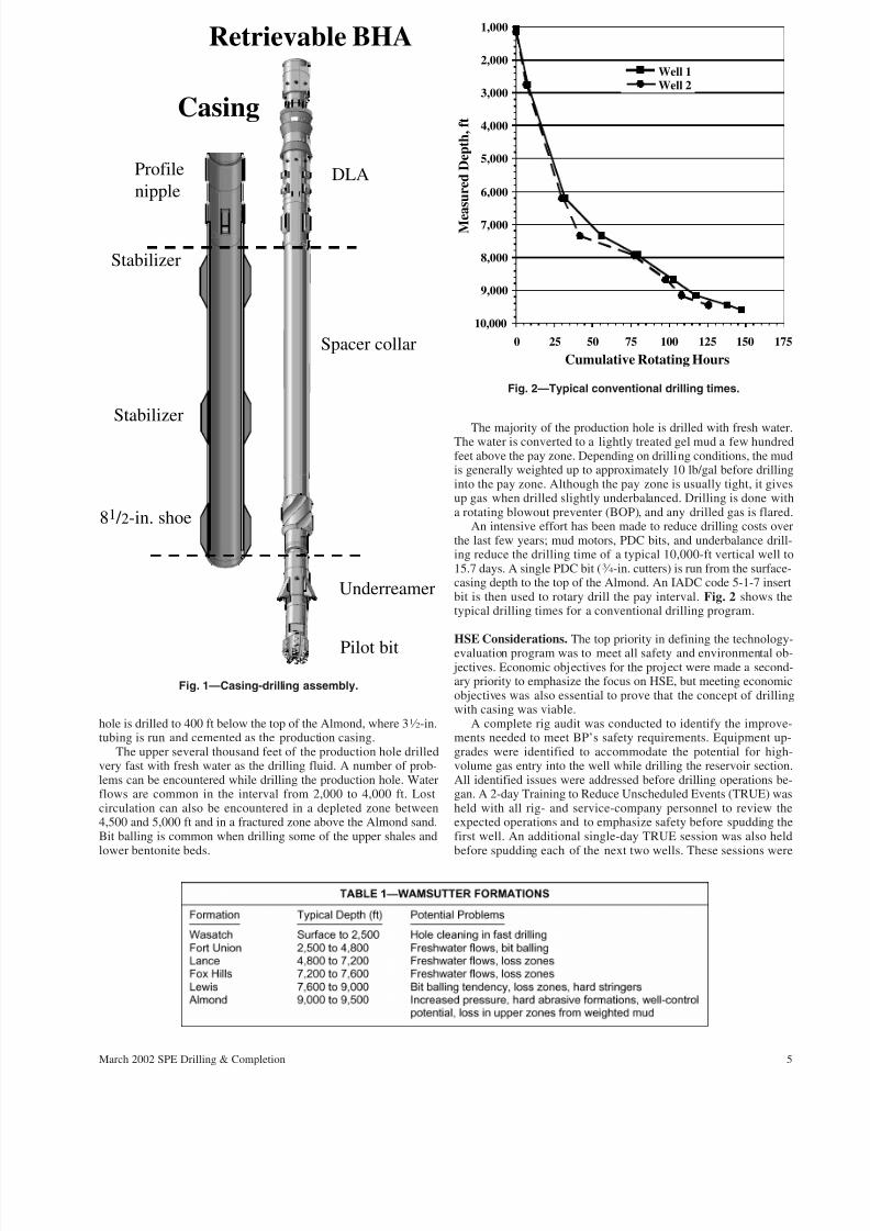
In most casing drilling applications, an underreamer is used
above a pilot bit to open the hole from the pilot-bit diameter to thefinal wellbore diameter. The pilot bit is sized to pass through the
casing, and the underreamer opens the hole to the size that is
normally drilled to run casing. For example, a 61 ⁄ 4-in. pilot bit and
an 81 ⁄ 2-in. underreamer are used while drilling with 7-in., 23-lb/ftcasing, as shown in Fig. 1.
An underreamer and pilot-bit assembly were used to casing-drill the 7-in. surface casing for all 15 wells in the BP project. A61 ⁄ 4-in. PDC casing shoe and a 37 ⁄ 8-in. PDC pilot bit were usedwith 41 ⁄ 2-in. casing to drill the production intervals of the first fourwells. The casing shoe was used instead of an underreamer be-cause of reliability concerns with the small underreamer and thedesire to evaluate the drilling potential with an even smaller casingsize. After the first four wells, the casing shoe/pilot bit combina-tion was abandoned because of the low penetration rate. The re-
maining wells were drilled with a conventional 61 ⁄ 4-in. PDC bitattached directly to the bottom joint of the casing. These wellswere drilled to total depth (TD), and the production casing wascemented in place without retrieving the PDC bit.
The casing drilling system uses a top drive to rotate the casing.Single joints of casing are picked up off the pipe rack and set in themouse hole. The top drive, with an extend feature, is connected tothe top of the joint, which is then stabbed into the top of the casingstring in the rotary table. The casing joint is drilled down by usingthe top drive in a conventional manner. The casing string is rotatedfor all operations except slide drilling with a motor and bent-housing assembly for oriented directional work.
Project Objectives. The primary objective of the project was toevaluate the potential of casing drilling technology to improve
drilling performance, both for Wamsutter and, more generally, forother BP locations worldwide. The operating costs at Wamsutterare significantly less than many other areas where casing drillingmight be employed. Openhole logs are normally not required be-cause of a wealth of offset well data. These factors made it a goodlocation to pilot test casing-drilling technology, even though theprobability of equaling conventional performance and economicsat this location was thought to be low.
The following specific goals were established for the project.• Get Health, Safety, Environment (HSE) right (no accidents,
no harm to people, and no damage to the environment).• Capture the key learnings and best practices to improve per-
formance on subsequent wells.• No unplanned tripping of casing.• Drill a useable production well to show that casing drilling is
a viable option to conventional drilling.
Field Environment. The Wamsutter area is located in the GreaterGreen River basin in south-central Wyoming. Gas production hasbeen under development since the early 1970s. The productiveformation is primarily the Almond sand, located at depths rangingfrom 8,000 to 10,000 ft. The Almond is a hard, tight sandstonewith native pressures of approximately 11 lb/gal.
The overlying Tertiary and Cretaceous formations are mostlysands and shales with interbedded coals and bentonite stringers.Table 1 shows the general lithology encountered in the area. Theconventional drilling program is to set 40 ft of 16-in. conductor,drill an 11-in. hole and set 85 ⁄ 8-in. casing at 1,150 ft. Then, a 77 ⁄ 8-in.
* Casing Drilling is a trademark of Tesco Corp., Calgary (1995).
Copyright © 2002 Society of Petroleum Engineers
This paper (SPE 76640) was revised for publication from paper SPE 67731, first presentedat the 2001 SPE/IADC Drilling Conference, Amsterdam, 27 February–1 March. Originalmanuscript received for review 18 May 2001. Revised manuscript received 18 December2001. Paper peer approved 21 December 2001.
4 March 2002 SPE Drilling & Completion
7/17/2019 *C*
http://slidepdf.com/reader/full/c563dba25550346aa9aa31d10 2/11
hole is drilled to 400 ft below the top of the Almond, where 31 ⁄ 2-in.tubing is run and cemented as the production casing.
The upper several thousand feet of the production hole drilledvery fast with fresh water as the drilling fluid. A number of prob-lems can be encountered while drilling the production hole. Waterflows are common in the interval from 2,000 to 4,000 ft. Lostcirculation can also be encountered in a depleted zone between4,500 and 5,000 ft and in a fractured zone above the Almond sand.Bit balling is common when drilling some of the upper shales andlower bentonite beds.
The majority of the production hole is drilled with fresh water.The water is converted to a lightly treated gel mud a few hundredfeet above the pay zone. Depending on drilling conditions, the mudis generally weighted up to approximately 10 lb/gal before drillinginto the pay zone. Although the pay zone is usually tight, it givesup gas when drilled slightly underbalanced. Drilling is done witha rotating blowout preventer (BOP), and any drilled gas is flared.
An intensive effort has been made to reduce drilling costs overthe last few years; mud motors, PDC bits, and underbalance drill-ing reduce the drilling time of a typical 10,000-ft vertical well to15.7 days. A single PDC bit (3 ⁄ 4-in. cutters) is run from the surface-casing depth to the top of the Almond. An IADC code 5-1-7 insertbit is then used to rotary drill the pay interval. Fig. 2 shows thetypical drilling times for a conventional drilling program.
HSE Considerations. The top priority in defining the technology-evaluation program was to meet all safety and environmental ob-
jectives. Economic objectives for the project were made a second-ary priority to emphasize the focus on HSE, but meeting economicobjectives was also essential to prove that the concept of drillingwith casing was viable.
A complete rig audit was conducted to identify the improve-ments needed to meet BP’s safety requirements. Equipment up-grades were identified to accommodate the potential for high-volume gas entry into the well while drilling the reservoir section.All identified issues were addressed before drilling operations be-gan. A 2-day Training to Reduce Unscheduled Events (TRUE) washeld with all rig- and service-company personnel to review theexpected operations and to emphasize safety before spudding thefirst well. An additional single-day TRUE session was also heldbefore spudding each of the next two wells. These sessions were
Casing
Stabilizer
Stabilizer
81 / 2-in. shoe
Profile
nipple
Underreamer
Pilot bit
DLA
Spacer collar
Retrievable BHA
Fig. 1—Casing-drilling assembly.
1,000
2,000
3,000
4,000
5,000
6,000
7,000
8,000
9,000
10,000
0 25 50 75 100 125 150 175
Cumulative Rotating Hours
M e a s u r e d D e p t h ,
f t
Well 1Well 2
Fig. 2—Typical conventional drilling times.
5March 2002 SPE Drilling & Completion

7/17/2019 *C*
http://slidepdf.com/reader/full/c563dba25550346aa9aa31d10 3/11
used to review the lessons learned and to fine-tune the upcomingdrilling program.
An outside safety consultant was used for the first well toensure a seamless meshing of the Tesco and BP safety programsand to assist in developing job-safety assessments (JSAs) for allthe special operations related to casing drilling. With the first well,onsite monitoring was provided by the consultant to ensure that theenvironmental and safety programs were fully implemented.
A well-control consulting firm, contracted to review all proce-dures relating to the underbalanced casing-drilling operation, con-firmed that the work could be conducted safely and that adequatecontingencies were in place before drilling commenced. Particularemphasis was placed on the wireline operations used to run andretrieve the BHA while the pay zone is exposed.
Rig Modifications. Tesco Rig 1, specifically designed as a casing-drilling rig, was used for the project.2 The rig uses computer-controlled, hydraulically powered rotating, hoisting, and pumpingsystems. The rig was originally designed and instrumented to assistin the development of casing-drilling systems.
A second mud pump was added to the rig, and improvementswere made to the well-control and gas-handling equipment. Theseenhancements ensured that the rig could safely handle a largeinflux of gas if high-pressure gas were encountered in naturalfractures. This equipment also facilitated the normal handling of reservoir gas while drilling slightly underbalanced.
A newly developed Tesco casing clamp, shown in Fig. 3, wasadded to the rig to increase the ease and efficiency of drilling withcasing. Before this, a crossover to the casing thread was used
below the top drive to screw into each joint of casing. This re-quired the casing threads to be made up and broken out beforebeing made up for the final time, increasing the risk of damagingthe threads.
The casing clamp handles casing sizes from 41 ⁄ 2 to 95 ⁄ 8 in. andeliminates the need to make a threaded connection between the topof the casing and the top drive. It incorporates external slips to hold
the casing axially and to transmit rotational torque. An internal spear-and-seal assembly provides a pressure-energized hydraulic seal.
The casing clamp is hydraulically operated with the top-drivecontrols. After placing a joint of casing in the mouse hole, a protec-tive, full-open thread nubbin is screwed into the box. The top drive isthen extended over the mouse hole, and the clamp is lowered overthe top of the casing. The clamp is activated, and the joint is pickedup and stabbed into the previous casing joint located in the rotarytable slips. The connection is made up to the thread manufacturer’sspecification, with the top drive and casing drilling resumed.
Engineering Considerations. A number of engineering issueswere addressed before the first well was spudded. These includedconsidering various options for bit-cutting structures that would bemost compatible with the formations, evaluating alternatives toprevent damage to the casing from buckling, and selecting anappropriate casing connection and a drilling fluid.
Cutting Structure. The formations drilled in the surface holeare generally quite soft with an occasional hard streak and arenormally drilled with an 11-in. IADC series 1-1-6 roller-cone bit.A Tesco PDC underreamer has proven to be quite robust when runwith roller-cone pilot bits in previous 7-in. casing-drilling activi-ties.3 This underreamer was used with a roller-cone bit, and noparticular effort was aimed at improving the cutting structure forthe surface hole.
The cutting structure planned for use in casing drilling theproduction hole was less well proven. The intention was to use aPDC drilling shoe that could last the entire production hole. Un-derreamers were to be used only as backup in case the casing shoe
wore out before reaching TD.In anticipation of trying to drill the entire production hole with
a PDC shoe, one of BP’s conventional wells was drilled to TD witha PDC bit to determine if a single bit could drill the completesection. Although the entire interval was drilled with a single PDCbit, it was not economical. However, it did prove that it should bepossible to drill to TD with a PDC drilling shoe.
Two different bit companies provided drilling shoes and pilotbits for the project. One shoe was designed with 1 ⁄ 2-in. cutters setin a tracking pattern on a six-bladed matrix body. The second shoeused 3 ⁄ 4-in. cutters on a five-bladed steel body. Fig. 4 shows bothshoes and pilot bits.
Fig. 3—Casing clamp. Fig. 4—Bits and shoes used in the production-hole section.
6 March 2002 SPE Drilling & Completion

7/17/2019 *C*
http://slidepdf.com/reader/full/c563dba25550346aa9aa31d10 4/11
Minimizing balling and preventing vibrations were the twomain considerations with the shoe and pilot-bit cutting structure.Bit balling with a conventional PDC bit is a known problem in theWamsutter area, and the combination of pilot bit and shoe wereexpected to intensify the tendency to ball. The second concern was
the dynamic stability of the pilot bit and shoe. Tests were con-ducted at a test facility to evaluate both concerns.The tests indicated that the matrix-body shoe and pilot bit were
less prone to balling than the steel-bladed shoe/bit, even thoughboth balled. Fig. 5 shows the shale packed in the junk slots of thesteel-body shoe after drilling shale under conditions similar tothose expected at Wamsutter. Fig. 6 shows that the matrix-bodyshoe was more aggressive and provided a higher penetration rate atlow weights, but both shoes began to ball at approximately 90 to130 ft/hr, or 10,000 to 15,000 lb of weight on bit (WOB).
The matrix-body shoe appeared to clean better, but the steel-body shoe/bit appeared to be more stable in tests conducted toevaluate dynamic stability. Stability tests were also conducted with
the 41 ⁄ 2-in. underreamer. While the underreamer was found to bequite stable, it ran off center, and the need for full-gauge stabilizerpads immediately below the blades was identified.
Based on this testing, it was decided to run the matrix-bodyshoe and three-bladed pilot bit immediately below the surfacecasing and to use the steel-body shoe as a backup if one wereneeded. The underreamers were also modified to include stabilizerpads below the blades.
Buckling. It was unclear at the beginning of the project howmuch bit weight would be required to drill with the casing-drilling
system. Conventional drilling in the area requires a relatively highWOB. Up to 25,000 lb while drilling with the 77 ⁄ 8-in. PDC bit abovethe pay and 35,000 lb for drilling the pay interval were used. Anarbitrary decision was made to design the drillstring to run the WOBas high as 25,000 lb while drilling a 61 ⁄ 4-in. hole in the pay zone.
This much weight requires approximately 2,500 ft of casing tobe run in compression and will buckle the lower section of thecasing string. The small clearance between the casing and holewall limits the buckling curvature, but the contact force can resultin increased wear on the casing connections.
Two options were considered to limit the wear. The first optionwas to run approximately 1,000 ft of 23.2-lb/ft, 5-in. casing, whichhas a very similar inner diameter (ID) to the 11.6-lb/ft, 41 ⁄ 2-in.casing, on the bottom of the string. Heavier casing reduces thebuckling and provides a thicker casing wall, allowing the distrib-uted wear to be insignificant.
The second option was to install rigid centralizers (Fig. 7) onthe casing. These centralizers were developed specifically for thecasing-drilling system, and a finite-element program was used todetermine the centralizer spacing.3 A total of 72 centralizers wereneeded to prevent wall contact and wear of the casing bodyor connections.
Both the centralizer and heavy-walled casing option have simi-lar costs. The centralizer option was chosen for the first wells toprovide some protection from differential sticking in the lost-circulation zones. A casing trip on the first well was planned toinspect the casing and to ensure that there was no excess wearbefore drilling into the pay zone.
Fig. 5—Shoe balled in testing.
Distance Drilled, in.
0 12 8 4 16
0
50
100
150
200 WOB/100
ROP, ft/hr
Steel-Body Shoe
0 12 8 4 16
0
50
100
150
200
Distance Drilled, in.
WOB/100
ROP, ft/hr
Matrix-Body Shoe
Fig. 6—Both the steel-bladed and matrix-body shoes balled at10,000 to 13,000 lb WOB.
7March 2002 SPE Drilling & Completion

7/17/2019 *C*
http://slidepdf.com/reader/full/c563dba25550346aa9aa31d10 5/11
Connections. An externally upset, wedge-thread connection
was chosen for the first two wells. This connection provides high
torsional strength and a relatively small coupling outer diameter
(OD) to help minimize equivalent circulating density (ECD).
While this connection was known to have a lower fatigue limit
than some other connections, fatigue life was not considered to be
critical, provided the centralizers controlled the buckling and the
hole was kept relatively straight.Work was also conducted with a tubular company to provide analternative, fatigue-resistant connection design based on a buttress-thread form. The design builds on knowledge gained from devel-oping fatigue-resistant connections for offshore production risers.Fatigue tests demonstrated that the connection was superior to thepublished fatigue rating of the wedge thread. Ultimately, thehigher torsional strength and smaller diameter of the wedge-threadconnection were chosen for the first two wells over the morefatigue-resistant, buttress-type connection.
Drilling Fluid. The upper sections of conventional wells weredrilled with fresh water. A freshwater, glycol drilling mud waschosen for casing drilling the first wells because of concerns aboutdifferential sticking and hole stability. In addition to providingenhanced hole stability, this mud helped counteract the increasedballing tendency of any water-based mud compared to clear water.
Surface-Hole Drilling
The surface hole in each well was drilled to approximately 1,200ft with the casing-drilling system. A Tesco underreamer and pilot-bit assembly were used for all 15 wells. A roller-cone bit was usedin Wells 1 and 2, while a PDC bit was used for the remaining 13wells. In each case, the BHA was installed at the surface andretrieved with the wireline when the casing point was reached. Thecement service company was called out before the casing pointwas reached. They began rigging up for the cement job before thewireline was run to retrieve the BHA.
Fig. 8 shows the time from spud to completion of the cement job for the first three casing-drilled wells compared to the averageoffset well. A typical offset takes approximately 8 to 12 hours todrill the surface hole and a total of approximately 19 hours (basedon the average of the last 19 wells in the field drilled since June2000) from spud to completion of the primary cement job.
The first casing-drilled well required 16.5 hours drilling time,and the total time from spud to completion of the cement job was21 hours. With the second well, the WOB and rpm were increasedto reduce the drilling time to 15 hours. Difficulties in retrieving theBHA, flowline plugging problems because of gumbo, and a sealfailure in the casing clamp increased the overall time to 26 hours.
For the third well, the rotating time was reduced to 8 hours, and theoverall time was reduced to 12.5 hours (excluding time waiting onweather). By the end of the Wamsutter casing-drilling program,the average time to drill and cement surface casing was approxi-mately 14 hours.
It was apparent after the first surface hole was completed thatthe most significant limitation to casing-drilling performance wasthe low ROP. The operating parameters for the first well werecontrolled rather conservatively. The rotary speed was held to 100rpm, and the WOB was limited to less than the casing weight, witha maximum of 15,000 lb.
More aggressive parameters were run on the second well in anattempt to improve the ROP. The rotary speed was increased to150 rpm, and the WOB was increased to the full weight of thecasing plus approximately one-half the top drive’s weight. This
resulted in the WOB being approximately 10,000 lb at the start of the well and ending at approximately 25,000 lb. The 7-in. casingdrilled smoothly with the more aggressive operating parametersbut resulted in only a slight improvement in the ROP.
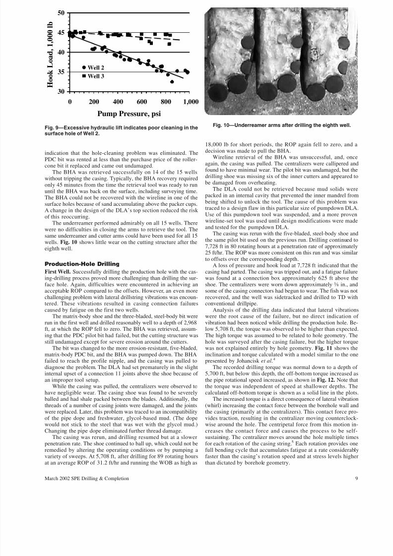
Problems with mud rings plugging the flowline were encoun-tered on the second well. Analysis of the drilling data indicates thatthese problems were more severe than recognized while drilling. Aplot of the hook load and flow rate (Fig. 9) while circulating off bottom at the casing point shows a large (10,000 lb) reduction inthe hook load, which indicates a significant restriction in the an-nulus. The restriction is believed to be caused by mud rings form-ing on the centralizers attached to the 7-in. casing. Back reamingseemed to slightly reduce the effect, but the problem returned soonafter drilling resumed.
The following actions were taken to counteract these problemsand to try to emulate conventional drilling conditions.
• The drilling fluid was switched to clear water circulated di-rectly from the reserve pit.
• Both pumps were run to increase the flow rate to 350 gal/min.• The roller-cone pilot bit was replaced with a PDC bit.• The WOB was limited to approximately one-half the
casing weight.These actions completely eliminated the low ROP observed on
the first and second wells. The surface hole was drilled with amaximum WOB of 6,000 lb, and the total rotating time was re-duced to 8 hours. There was no indication of mud rings or hole-cleaning problems. Fig. 9 shows little change in the hook load atthe casing point as a function of the flow rate. This is further
0
5
10
15
20
25
30
Average
offsets
First well Second
well
Third well
T i m e ,
h o u r s
Total time
Drilling time
Fig. 8—Drilling and cementing time for surface hole.
Fig. 7—Rigid centralizer.
8 March 2002 SPE Drilling & Completion
7/17/2019 *C*
http://slidepdf.com/reader/full/c563dba25550346aa9aa31d10 6/11
indication that the hole-cleaning problem was eliminated. ThePDC bit was rented at less than the purchase price of the roller-cone bit it replaced and came out undamaged.
The BHA was retrieved successfully on 14 of the 15 wellswithout tripping the casing. Typically, the BHA recovery requiredonly 45 minutes from the time the retrieval tool was ready to rununtil the BHA was back on the surface, including surveying time.The BHA could not be recovered with the wireline in one of thesurface holes because of sand accumulating above the packer cups.A change in the design of the DLA’s top section reduced the risk of this reoccurring.
The underreamer performed admirably on all 15 wells. Therewere no difficulties in closing the arms to retrieve the tool. Thesame underreamer and cutter arms could have been used for all 15wells. Fig. 10 shows little wear on the cutting structure after theeighth well.
Production-Hole Drilling
First Well. Successfully drilling the production hole with the cas-ing-drilling process proved more challenging than drilling the sur-face hole. Again, difficulties were encountered in achieving an
acceptable ROP compared to the offsets. However, an even morechallenging problem with lateral drillstring vibrations was encoun-tered. These vibrations resulted in casing connection failurescaused by fatigue on the first two wells.
The matrix-body shoe and the three-bladed, steel-body bit wererun in the first well and drilled reasonably well to a depth of 2,968ft, at which the ROP fell to zero. The BHA was retrieved, assum-ing that the PDC pilot bit had failed, but the cutting structure wasstill undamaged except for severe erosion around the cutters.
The bit was changed to the more erosion-resistant, five-bladed,matrix-body PDC bit, and the BHA was pumped down. The BHAfailed to reach the profile nipple, and the casing was pulled todiagnose the problem. The DLA had set prematurely in the slightinternal upset of a connection 11 joints above the shoe because of an improper tool setup.
While the casing was pulled, the centralizers were observed tohave negligible wear. The casing shoe was found to be severelyballed and had shale packed between the blades. Additionally, thethreads of a number of casing joints were damaged, and the jointswere replaced. Later, this problem was traced to an incompatibilityof the pipe dope and freshwater, glycol-based mud. (The dopewould not stick to the steel that was wet with the glycol mud.)Changing the pipe dope eliminated further thread damage.
The casing was rerun, and drilling resumed but at a slowerpenetration rate. The shoe continued to ball up, which could not beremedied by altering the operating conditions or by pumping avariety of sweeps. At 5,708 ft, after drilling for 89 rotating hoursat an average ROP of 31.2 ft/hr and running the WOB as high as
18,000 lb for short periods, the ROP again fell to zero, and adecision was made to pull the BHA.
Wireline retrieval of the BHA was unsuccessful, and, onceagain, the casing was pulled. The centralizers were callipered andfound to have minimal wear. The pilot bit was undamaged, but thedrilling shoe was missing six of the inner cutters and appeared tobe damaged from overheating.
The DLA could not be retrieved because mud solids were
packed in an internal cavity that prevented the inner mandrel frombeing shifted to unlock the tool. The cause of this problem wastraced to a design flaw in this particular size of pumpdown DLA.Use of this pumpdown tool was suspended, and a more provenwireline-set tool was used until design modifications were madeand tested for the pumpdown DLA.
The casing was rerun with the five-bladed, steel-body shoe andthe same pilot bit used on the previous run. Drilling continued to7,728 ft in 80 rotating hours at a penetration rate of approximately25 ft/hr. The ROP was more consistent on this run and was similarto offsets over the corresponding depth.
A loss of pressure and hook load at 7,728 ft indicated that thecasing had parted. The casing was tripped out, and a fatigue failurewas found at a connection box approximately 625 ft above theshoe. The centralizers were worn down approximately 3 ⁄ 8 in., and
some of the casing connectors had begun to wear. The fish was notrecovered, and the well was sidetracked and drilled to TD withconventional drillpipe.
Analysis of the drilling data indicated that lateral vibrationswere the root cause of the failure, but no direct indication of vibration had been noticed while drilling the production hole. Be-low 5,708 ft, the torque was observed to be higher than expected.The high torque was assumed to be related to hole geometry. Thehole was surveyed after the casing failure, but the higher torquewas not explained entirely by hole geometry. Fig. 11 shows theinclination and torque calculated with a model similar to the onepresented by Johancisk et al.4
The recorded drilling torque was normal down to a depth of 5,700 ft, but below this depth, the off-bottom torque increased asthe pipe rotational speed increased, as shown in Fig. 12. Note thatthe torque was independent of speed at shallower depths. Thecalculated off-bottom torque is shown as a solid line in the plots.
The increased torque is a direct consequence of lateral vibration(whirl) increasing the contact force between the borehole wall andthe casing (primarily at the centralizers). This contact force pro-vides traction, resulting in the centralizer moving counterclock-wise around the hole. The centripetal force from this motion in-creases the contact force and causes the process to be self-sustaining. The centralizer moves around the hole multiple timesfor each rotation of the casing string.5 Each rotation provides onefull bending cycle that accumulates fatigue at a rate considerablyfaster than the casing’s rotation speed and at stress levels higherthan dictated by borehole geometry.
30
35
40
45
50
0 200 400 600 800 1,000
Pump Pressure, psi
H o o k L o a d ,
1 , 0
0 0 l b
Well 2
Well 3
Fig. 9—Excessive hydraulic lift indicates poor cleaning in thesurface hole of Well 2.
Fig. 10—Underreamer arms after drilling the eighth well.
9March 2002 SPE Drilling & Completion

7/17/2019 *C*
http://slidepdf.com/reader/full/c563dba25550346aa9aa31d10 7/11
Slippage between the centralizer and borehole wall creates torqueand results in wear of the centralizers. Warren et al.6 show a corre-lation between downhole recorded acceleration data and surfacetorque that supports the conclusion that lateral vibration was respon-sible for the torque, wear, and ultimate fatigue failure of the casing.
No definitive reason was identified to explain why the lateral
vibrations did not occur above 5,700 ft but were so severe below5,700 ft. It is surmised that the vibrations were initiated by theincrease and then decrease in the hole inclination and might beprevented with a more stabilized drilling assembly.
The most significant problem identified in the first well was thefailure of the casing, although slow penetration rates were alsoexperienced in the upper hole sections. The casing failure wasclearly caused by fatigue-induced lateral vibrations. Because theonset of the vibrations was at a depth of 5,700 ft, where theinclination reached a maximum and began to decrease, it wasconcluded that hole geometry played a significant role in causingthe vibrations.
Second Well. A two-pronged approach was developed for miti-gating the vibrations on the second well. First, the diameter of sixcentralizers immediately above the bit was increased from approxi-mately 5.625 to 6.125 in. The purpose of this was to provide addi-tional stabilization to counteract the normal deviation of the for-mations so that the hole would remain straighter and more vertical.
The second prong of the vibration-mitigation program was totrain the drilling crew to monitor the on- and off-bottom torqueregularly to identify the onset of vibrations. The operating param-eters were to be altered to stop the vibrations as soon as they wereobserved. The drillstring rotation would be stopped and restarted toarrest the vibrations. Rotary speeds would be reduced to drill at acondition that was less conducive to initiating vibrations.
Lateral vibrations were observed immediately after beginningdrilling on the cement plug for the second well. At this shallow
depth, the drilling crew could see the casing walk counterclock-
wise around the rotary table while observing the increase in torque.They could also pick the bit up off the bottom and see that the torque
remained high until the rotation was stopped and restarted. These
observations were quite convincing that the onset of vibrationscould be detected by carefully monitoring the drilling parameters.
As drilling progressed, the surface indications of lateral vibra-tions gradually disappeared, but the drilling parameters indicatedthat the vibrations were worse than with the first well. The plots of off-bottom torque in Fig. 13 indicate the severity of the vibration.Even though the increase in diameter of the bottom six centralizerssignificantly reduced the deviation, it also increased the tendencyfor casing whirl.
The vibration could not be mitigated with any of the plannedtechniques. The casing failed at the last thread on the pin of thecasing joint that screwed into the profile nipple at a depth of 4,885ft. The failure was immediately detected, and the BHA was re-trieved with the wireline before tripping the casing out. The profilenipple and shoe were recovered, and the well was again completedwith conventional drillpipe.
The surfaces of the failed connection clearly indicated that thefailure was caused by fatigue, and all the downhole tools showedsymptoms of severe vibration. The pilot bit was still in good con-dition, but all the gauge trimmers on the matrix-body shoe weredamaged, and the matrix blades were broken in two places so thattwo ID cutters were missing. The centralizers were worn signifi-cantly, even though they were not worn at all at the same depth onthe first well, in which lateral vibrations did not start until 5,700 ft.None of the centralizers had come loose or moved on the casing,
0
1,000
2,000
3,000
4,000
5,000
6,000
7,000
8,000
0 5 10
Inclination
and Dogleg
M e a s u r e d D e
p t h ,
f t
Inclination
Dogleg
0 500 1,000 1,500
Off-Bottom Torque, ft-lb
Calculated
Torque
Fig. 11—Inclination and torque from the first well.
0
800
1,600
2,400
0 20 40 60 80 100
T o r q u e , f t - l b 5,707 to 6,700 ft
0
800
1,600
2,400
0 50 100 150
T o r q u e , f t - l b
3,000 to 4,000 ft
0
800
1,600
2,400
0 25 50 75 100 125
Rotary Speed, rpm
T o r q u e , f t - l b
6,700 to 7,700 ft
Calculated torque
Fig. 12—Off-bottom torque response indicating lateral vibrationin the first well.
10 March 2002 SPE Drilling & Completion

7/17/2019 *C*
http://slidepdf.com/reader/full/c563dba25550346aa9aa31d10 8/11
even under the severe conditions experienced with this and the
previous well.
The failure of the second well confirmed the diagnosis that high
bending stresses caused by lateral vibrations led to fatigue failures
in the casing, but the solutions tried for the problem were unsuc-
cessful. While drilling the first two wells, both the torque and the
WOB requirements were better defined. This allowed a rethinking
of the whole casing design.
Third and Fourth Wells. The casing design for the third well was
changed to reduce the probability that lateral vibrations would
occur, and the couplings were changed to a more fatigue-resistant,
buttress-thread form. Twenty-four joints of 5-in., 23.2-lb/ft casing
were run on the bottom to replace the 41 ⁄ 2-in. centralized casing
used in the previous design. This casing has sufficient weight so
that the coupled 41 ⁄ 2-in. casing is not in compression and provides
a smoother surface to reduce the friction that increases the ten-
dency to whirl and a thicker wall to better withstand the wear onthe casing body.
The casing connection was changed to one based on the but-tress-thread form that was specifically designed and tested forcasing drilling. The 5-in. flush connections provided both an in-ternal and external torque shoulder with a torque rating of 18,000ft-lb. The coupled connection used on the 41 ⁄ 2-in. casing used thesame pin but butted the pin ends together to provide a torque ratingof 7,900 ft-lb. The rig crew found these connections easier to makeup and handle than those used previously.
Fatigue testing of the coupling indicated that it should run far
more than 1 million cycles at the stress levels expected in the well.
A sample of the actual 41 ⁄ 2-in. casing to be used on the well was
made up to 10,000 ft-lb before the torque turn plot indicated yield-
ing. The torque was then increased to 14,000 ft-lb, and the connection
drifted to demonstrate that excessive torque was not likely to deform
the pin ends sufficiently to prevent the BHA from being retrieved.The third well was successfully casing-drilled from the surface
casing shoe to TD with the retrievable drilling assembly. Drilling
proceeded to 4,475 ft with fresh water as the drilling fluid. Over
this interval, the flow rates were as high as 290 gal/min (380
ft/min) with a rotary speed of approximately 130 rpm and a rela-
tively low WOB. This interval was drilled at an average ROP of 52ft/hr, which was better than both the previous wells but was stillslow relative to the offsets. The high hydraulics and clear-waterdrilling fluid did not eliminate the shoe-balling problem, but theydid make it much easier to clean the bit and shoe after they balled.
Drilling continued to 7,435 ft with a rotary speed of 110 rpmand a flow rate of 210 gal/min after the well was mudded up. Atthat point, the ROP decreased sufficiently to indicate that either thebit or the shoe was worn. The BHA was retrieved with the wireline
after having been in the well for 219 hours (191.5 rotating hours)and drilling 6,251 ft. The bit was severely eroded from the highflow rates used in the upper part of the hole. One of the innercutters was missing, and others were worn but not sufficientlyworn to account for the observed decrease in the drilling rate.There was no damage to any of the drilling tools from vibrations,no sand on the inside the DLA, and only moderate erosion to theflow tube in the DLA.
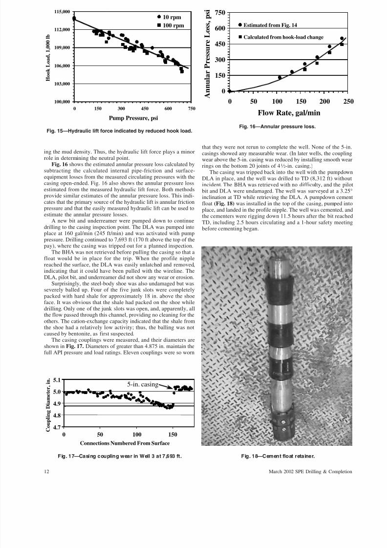
While the casing was open-ended after pulling the BHA at7,435 ft, flow tests were run to better determine the annular pres-sure loss. Fig. 14 shows standpipe pressure vs. flow rate whilerotating at 10 and at 100 rpm. There appears to be only a veryslight rotary-speed effect on the pressure loss. Fig. 15 shows thehook-load readings at these flow rates and indicates a hydraulic liftforce of approximately 8,000 lb. This force is not substantiallydifferent from the hydraulic lift observed while drilling at the samedepth with the centralized, flush-jointed pipe of the first well.
The magnitude of the hydraulic lift force is approximately thesame as the WOB, which could raise concerns about keeping theneutral point below the top of the thick-walled, 5-in. casing. Theneutral point is the highest point in the casing at which bucklingcan occur, but it is not necessarily the point of zero axial stress.Rather, it is the location in the casing where the axial compressivestress equals the average of the radial and tangential stress.7 Theannular pressure that causes the hydraulic lift force not only in-creases the axial stress in the casing, but also increases the otherstresses so that there is little net change in the neutral point becauseof the hydraulic lift effect. This is similar to the effect of increas-
0
200
400
600
800
0 50 100 150 200 250
Flow Rate, gal/min
S t a n d p i p e P r e s s u r e , p s i 10 rpm
100 rpm
Fig. 14—Measured standpipe pressure at 7,435 ft with the DLAand BHA removed from the casing string.
0
800
1,600
2,400
0 40 80 120 160
T o r q u e ,
f t - l b 2,494 to 2,694 ft
0
800
1,600
2,400
0 40 80 120 160
T o r q u e ,
f t - l b 2,694 to 3,443 ft
0
800
1,600
2,400
0 40 80 120 160
Rotary Speed, rpm
T o r q u e , f
t - l b
3,443 to 4,152 ft
Fig. 13—Off-bottom torque increase with increased rotaryspeed indicates lateral vibrations in the second well.
11March 2002 SPE Drilling & Completion
7/17/2019 *C*
http://slidepdf.com/reader/full/c563dba25550346aa9aa31d10 9/11
ing the mud density. Thus, the hydraulic lift force plays a minorrole in determining the neutral point.
Fig. 16 shows the estimated annular pressure loss calculated bysubtracting the calculated internal pipe-friction and surface-equipment losses from the measured circulating pressures with thecasing open-ended. Fig. 16 also shows the annular pressure loss
estimated from the measured hydraulic lift force. Both methodsprovide similar estimates of the annular pressure loss. This indi-cates that the primary source of the hydraulic lift is annular frictionpressure and that the easily measured hydraulic lift can be used toestimate the annular pressure losses.
A new bit and underreamer were pumped down to continuedrilling to the casing inspection point. The DLA was pumped intoplace at 160 gal/min (245 ft/min) and was activated with pumppressure. Drilling continued to 7,693 ft (170 ft above the top of thepay), where the casing was tripped out for a planned inspection.
The BHA was not retrieved before pulling the casing so that afloat would be in place for the trip. When the profile nipplereached the surface, the DLA was easily unlatched and removed,indicating that it could have been pulled with the wireline. TheDLA, pilot bit, and underreamer did not show any wear or erosion.
Surprisingly, the steel-body shoe was also undamaged but was
severely balled up. Four of the five junk slots were completelypacked with hard shale for approximately 18 in. above the shoeface. It was obvious that the shale had packed on the shoe whiledrilling. Only one of the junk slots was open, and, apparently, allthe flow passed through this channel, providing no cleaning for theothers. The cation-exchange capacity indicated that the shale fromthe shoe had a relatively low activity; thus, the balling was notcaused by bentonite, as first suspected.
The casing couplings were measured, and their diameters areshown in Fig. 17. Diameters of greater than 4.875 in. maintain thefull API pressure and load ratings. Eleven couplings were so worn
that they were not rerun to complete the well. None of the 5-in.casings showed any measurable wear. (In later wells, the couplingwear above the 5-in. casing was reduced by installing smooth wearrings on the bottom 20 joints of 41 ⁄ 2-in. casing.)
The casing was tripped back into the well with the pumpdownDLA in place, and the well was drilled to TD (8,312 ft) withoutincident. The BHA was retrieved with no difficulty, and the pilot
bit and DLA were undamaged. The well was surveyed at a 3.25°inclination at TD while retrieving the DLA. A pumpdown cementfloat (Fig. 18) was installed in the top of the casing, pumped intoplace, and landed in the profile nipple. The well was cemented, andthe cementers were rigging down 11.5 hours after the bit reachedTD, including 2.5 hours circulating and a 1-hour safety meetingbefore cementing began.
100,000
103,000
106,000
109,000
112,000
115,000
0 150 300 450 600 750
Pump Pressure, psi
H o o k L o a d ,
1 , 0
0 0 l b
10 rpm
100 rpm
Fig. 15—Hydraulic lift force indicated by reduced hook load.
0
150
300
450
600
750
0 50 100 150 200 250
Flow Rate, gal/min
A
n n u l a r P r e s s u r e L o s s , p s i
Estimated from Fig. 14
Calculated from hook-load change
Fig. 16—Annular pressure loss.
4.7
4.8
4.9
5.0
5.1
0 50 100 150
Connections Numbered From Surface
C o u p l i n g D i a m e t e r , i n .
5-in. casing
Fig. 17—Casing coupling wear in Well 3 at 7,693 ft. Fig. 18—Cement float retainer.
12 March 2002 SPE Drilling & Completion

7/17/2019 *C*
http://slidepdf.com/reader/full/c563dba25550346aa9aa31d10 10/11
None of the downhole equipment used in the third well showedany evidence of damage from lateral vibrations. This was consis-tent with the torque observations made while drilling the well.Fig. 19 shows the off-bottom torque as the rotary speed was variedat three depths in the well. A similar response was observed at allother depths. The constant torque indicates that the casing was notsubjected to significant lateral vibration; therefore, the solution tothis problem was successful.
The completion of the third well with the casing-drilling systemrepresented a number of milestones. At that time, it was the deep-est well ever completed with the casing-drilling system in whichall segments of the well were drilled with casing. There was nounplanned tripping of the casing. It represented the single longestrun and successful retrieval of the pumpdown DLA. It was the firstwell in which the pumpdown cementing float was used successfully.
The production hole of the fourth well was drilled successfullywith the PDC casing shoe and the retrievable drilling assemblywithout tripping the casing. As in the third well, all the casing-drilling equipment worked successfully, but the drilling rate wasstill not competitive with the conventionally drilled wells.
Final 11 Wells. The remaining 11 wells were drilled with a PDCbit attached directly to the casing. This was acceptable to theoperator because no openhole logs were required for the wells.This improved the penetration rate, making the wells competitivewith conventional wells drilled with a PDC bit and performancemud motor.
The eighth well drilled with the casing-drilling system wascompleted in 8.1 days. This is the third-fastest well completed outof several hundred Wamsutter wells drilled by BP. Two of thesubsequent wells failed to make TD with a single PDC bit and,thus, required a casing trip to change the bit. The casing-drillingprogram was terminated after drilling 15 wells because of a re-duction in the overall drilling program. At that time, work was stillin progress to find a bit that would consistently drill to TD withouthaving a significant reduction in the ROP in the pay zone becauseof cutter wear. The overall average for the 11 wells drilled with thePDC bit was 14.0 days from spud to rig release.
Conclusions
Fifteen wells were drilled in the Wamsutter casing-drilling pilotproject. Considerable progress was made in understanding the is-sues affecting casing drilling and in improving the process. Well 8was drilled to TD and cemented in just 8.1 days. This is thethird-fastest well ever drilled in the area.
Overall, the casing-drilling performance was comparable to thebest conventionally drilled wells, but no overall cost advantagewas realized. This is not surprising, considering that Wamsutterwells are relatively simple, involve low rig costs, have limited drill-string tripping, experience no difficulty in running the casing, andhave undergone an extensive program for optimizing conventionaldrilling practices during the last 20 years of development drilling.
Experience to date demonstrates that casing drilling can reducethe time required to drill and cement the surface casing. Thisobservation is consistent with the results of an offshore project, in
which the 121 ⁄ 4-in. surface holes were casing-drilled.8
The largersurface casing rotates more smoothly, allowing underreamers thatare more robust, with dedicated jets for each arm. Once compa-rable penetration rates are achieved, time savings result fromeliminating hole conditioning, conventional drillstring tripping andcasing running, and the time required to lay down large drill col-lars. The casing-drilling process also reduces the risk of not gettingcasing to the bottom after the surface hole is drilled.
The casing clamp used on the Wamsutter project worked wellto facilitate the handling of the casing with minimal thread damagewhile drilling and has become an essential piece of equipment forcasing drilling.
The jury is still out on the potential for casing drilling to impactdrilling times for small casing sizes. Significant progress duringthe Wamsutter project was made in designing the casing string to
run smoothly. Improvements have been made in assuring that theDLA can be successfully pumped into place and retrieved whendesired. The life of the 41 ⁄ 2-in. DLA is acceptable, showing littleerosion after 191 rotating hours while pumping at rates as high as290 gal/min. Reliability improved to the point where the DLAcould be retrieved and reset with confidence.
The major impediment limiting casing-drilling performancewith wireline-retrievable tools in the production hole at Wamsutterwas the relatively low penetration rates in the upper hole sections.The ROP was limited by inadequate cleaning of the casing shoe,and no effective way to keep the shoe clean was found. Thisproblem was solved by eliminating the PDC casing shoe and at-taching a nonrecoverable 61 ⁄ 4-in. PDC bit directly to the bottom
joint of the casing and drilling to TD.At the beginning of the project, wellbore stability, lost circu-
lation, and gas flows were expected to be major problems becausethey are for conventional drilling operations in the Wamsutter area.Actual experience showed that a casing-drilled wellbore remainedstable even when drilling underbalanced with water. In addition,no significant mud losses or well-control incidents were experi-enced. From limited operational experience, it appears that theprocess of casing drilling mechanically strengthens the wellboreby building and maintaining an impermeable layer on the wellbore.
Based on the knowledge gained to date, the casing-drillingsystem in its current state of development is well suited for drillingsofter formations with casing sizes of 7 in. or larger. In thesesituations, the penetration rate can easily match conventional rates,and the reduced tripping and drillstring handling can be used ad-
0
800
1,600
2,400
0 50 100 150
T o r q u e , f t - l b 3,500 to 3,800 ft
0
800
1,600
2,400
0 50 100 150
T o r q u e , f t - l b
1,200 to 1,800 ft
0
800
1,600
2,400
0 25 50 75 100 125
Rotary Speed, rpm
T o r q u e ,
f t - l b
7,435 ft
Fig. 19—Off-bottom torque indicates no lateral vibration in thethird well.
13March 2002 SPE Drilling & Completion

7/17/2019 *C*
http://slidepdf.com/reader/full/c563dba25550346aa9aa31d10 11/11
vantageously. This is particularly true in situations in which dif-ficulty may be encountered in running the casing after the hole isdrilled. These time savings are significant for drilling operationswith higher spread costs. The increasing confidence that the BHAcan be retrieved successfully reduces the risk of using the casing-drilling system in these high-cost situations.
As use of the casing-drilling system increases, experience and equip-ment refinements will allow the technology to have broader applica-tions, and it promises to impact a greatervarietyof drilling operations.
Acknowledgments
We wish to express our appreciation to the management of BPAmerica Production Co. and Tesco for their support of theWamsutter casing-drilling project and for allowing this paper to bepublished. Thanks to David Oryall and Julian Lopushinsky forfield support during the project, to Hughes Christensen for testingthe bits and casing shoes, and to Grant Prideco for fatigue tests of the Drilling With Casing connection.
References
1. Tessari, R.M. et al.: “Drilling With Casing Promises Major Benefits,”
Oil and Gas J. (1999) 97, No. 20, 58.
2. Laurent, M., Angman, P., and Oveson, D.: “Hydraulic Rig Supports
Casing Drilling,” World Oil (1999) 220, No. 9, 61.
3. Warren, T.M., Angman, P., and Houtchens, B.: “Casing Drilling Ap-
plication Design Considerations,” paper SPE 59179 presented at the
2000 IADC/SPE Drilling Conference, New Orleans, 23–25 February.
4. Johancisk, C.A., Friesen, D.B., and Dawson, R.: “Torque and Drag in
Directional Wells—Prediction and Measurement,” JPT (June 1984) 987.
5. Vandiver, J.K., Nicholson, J.W., and Shyu, R.-J.: “Case Studies of the
Bending Vibration and Whirling Motion of Drill Collars,” SPEDE
(December 1990) 282.
6. Warren, T.M. et al.: “Shock Sub Performance Testing,” paper SPE
39323 presented at the 1998 IADC/SPE Drilling Conference, Dallas,
3–6 March.
7. Hammerlindl, D.J.: “Basic Fluid and Pressure Forces on Oilwell Tu-
bulars,” JPT (January 1980) 153.
8. Warren, T.M., Houtchens, B., and Portas Jr., W.R.: “Directional Drill-
ing With Casing Reduces Drilling Time,” Offshore Magazine (2001)
61, Nos. 1 and 2.
SI Metric Conversion Factors
ft × 3.048* E–01 m
gal/min × 3.785 4 E+00 L/min
in. × 2.54* E+00 cm
Ibf × 4.448 222 E+00 N
lbm × 4.535 924 E–01 kg
psi × 6.894 757 E+00 kPa
lb/ft × 1.488 146 E+00 kg/m
*Conversion factor is exact.
S.F. Shepard is currently working in BP’s Lower 48 Business Unit asthe lead drilling engineer for the Wamsutter field. e-mail:[email protected]. Before this assignment, she worked as botha drilling engineer and a site supervisor and has held variousdrilling assignments in Argentina, Poland, Romania, the U.K.,and the United States. Shepard holds a BS degree in petroleumengineering from Texas A&M U. R.H. Reiley is a project man-ager of Underbalance Drilling Technology for BP’s UpstreamTechnology Group. He travels worldwide as a technology con-sultant, promoting the development and application of newtechnology. Before being transferred to Houston, he was thehead of drilling operations for ADCO Onshore Oil Operations inAbu Dhabi. He joined BP in 1973 after working 3 years forTexaco. He has held operations and drilling-management po-sitions in Alaska, California, London, and the United Arab Emir-ates. Reiley holds a BS degree in mining engineering and anMS degree in engineering management, both from the U. of
Alaska. T.M. Warren is currently the director of research anddevelopment for Tesco Corp., involved primarily with exploit-ing casing-drilling technology. e-mail: [email protected] previously worked for Amoco, where he directed the re-search on roller-cone bit mechanics, drag bit mechanics, di-rectional drilling, drillstring mechanics, high-speed drilling sys-tems, and rock mechanics related to drilling. Warren holds BSand MS degrees in mineral engineering from the U. of Ala-bama. He was the recipient of the 1982 AIME Rossiter W. Ray-mond Award, the 1985 SPE Cedric K. Ferguson Award, and the1997 SPE Drilling Engineering Award. He is active in SPE techni-cal programs and served as Chairman of the 1999 AnnualTechnical Conference and Exhibition.
14 March 2002 SPE Drilling & Completion