Embed Size (px)
Citation preview

COMMON STRUCTURAL RULES FOR BULK CARRIERS
JULY 2012
Corrigenda 1
Rule Editorials
Notes: (1) These Rule Corrigenda enter into force on 1st July 2012. (2) These Rule Corrigenda should be read in conjunction with the July 2012 consolidated
edition of Bulk Carriers CSR. Copyright in these Common Structural Rules for Bulk Carriers is owned by: American Bureau of Shipping Bureau Veritas China Classification Society Det Norske Veritas Germanischer Lloyd Korean Register of Shipping Lloyd's Register Nippon Kaiji Kyokai Registro Italiano Navale Russian Maritime Register of Shipping Copyright © 2012 The IACS members, their affiliates and subsidiaries and their respective officers, employees or agents are, individually and collectively, referred to in this clause as the ‘IACS Members’. The IACS Members, individually and collectively, assume no responsibility and shall not be liable to any person for any loss, damage or expense caused by reliance on the information or advice in this document or howsoever provided, unless that person has signed a contract with the relevant IACS Member entity for the provision of this information or advice and in that case any responsibility or liability is exclusively on the terms and conditions set out in that contract.


Common Structural Rules for Bulk Carriers July 2012 Edition
Corrigenda 1 to July 2012 Edition i / iv
For technical background for Rule Corrigenda in this present document, reference is made to separate document Technical Background for Rule Corrigenda.

Common Structural Rules for Bulk Carriers July 2012 Edition
ii / iv Corrigenda 1 to July 2012 Edition
List of changes
CHAPTER 2 GENERAL ARRANGEMENT DESIGN ............................................................ 1
Section 1 Subdivision Arrangement ................................................................................... 1
3. After peak, machinery space bulkheads and stern tubes ..................................................... 1 3.1.5 Stern Tubes..........................................................................................................................1
CHAPTER 6 HULL SCANTLINGS...................................................................................... 2
Section 3 Buckling and ultimate strength of ordinary stiffeners and stiffened panels .. 2
Symbols......................................................................................................................................... 2
CHAPTER 11 CONSTRUCTION AND TESTING................................................................... 3
Section 3 Testing of Compartments.................................................................................... 3
2 Testing Method ................................................................................................................. 3 2.3 Hose Testing........................................................................................................................3
2.3.1 ...............................................................................................................................3
CHAPTER 13 SHIPS IN OPERATION, RENEWAL CRITERIA.............................................. 4
Section 1 Maintenance of Class........................................................................................... 4
1 General .............................................................................................................................. 4 1.1 Application ..........................................................................................................................4
1.1.2 Void .......................................................................................................................4 1.1.3 Void .......................................................................................................................4
1.2 Definitions ...........................................................................................................................4 1.2.3 Deck zone ..............................................................................................................4 1.2.4 Bottom zone ...........................................................................................................5 1.2.5 Neutral axis zone ...................................................................................................5
Section 2 Thickness Measurement and acceptance criteria ............................................. 5 Symbols ..........................................................................................................................................5
1 Application........................................................................................................................ 6 1.1.1 General ................................................................................................................................6
1.1.1 ...............................................................................................................................6
2 Rule requirements for the extent of measurements and the determination of locations............................................................................................................................. 6
2.1 General ................................................................................................................................6 2.1.1 ...............................................................................................................................6
2.2 Class renewal survey ...........................................................................................................7 2.2.1 ...............................................................................................................................7 2.2.2 ...............................................................................................................................8
2.3 Number and locations of measurements..............................................................................8 2.3.1 Number of measurements ......................................................................................8

Common Structural Rules for Bulk Carriers July 2012 Edition
Corrigenda 1 to July 2012 Edition iii / iv
2.3.2 Locations of measurements ...................................................................................8
3. Acceptance Criteria........................................................................................................ 13 3.1 Definitions .........................................................................................................................13
3.1.1 Deck zone ............................................................................................................13 3.1.2 Bottom zone .........................................................................................................14 3.1.3 Neutral axis zone .................................................................................................14
3.2 Local strength criteria........................................................................................................14 3.2.1 Items for the local strength criteria.....................................................................14 3.2.2 Renewal thickness for corrosion other than local corrosion...............................15 3.2.3 Renewal thickness for local corrosion.................................................................15
3.3 Global strength criteria ......................................................................................................16 3.3.1 Items for the global strength criteria...................................................................16 3.3.2 Renewal thickness................................................................................................16
Section 2 Acceptance criteria ............................................................................................ 17
Symbols....................................................................................................................................... 17
1. Local strength criteria.................................................................................................... 18 1.1 Application ........................................................................................................................18
1.1.1 .............................................................................................................................18 1.2 Renewal thickness for corrosion other than local corrosion..............................................18
1.2.1 .............................................................................................................................18 1.3 Renewal thickness for local corrosion...............................................................................18
1.3.1 .............................................................................................................................18 1.4 Global strength criteria ......................................................................................................19
1.4.1 Items for the global strength criteria...................................................................19 1.4.2 Renewal thickness................................................................................................19


Common Structural Rules for Bulk Carriers July 2012 Edition
Corrigenda 1 to July 2012 Edition 1
Chapter 2 GENERAL ARRANGEMENT DESIGN
Section 1 Subdivision Arrangement
3. After peak, machinery space bulkheads and stern tubes
The following text unintentionally removed from the last revision is reinstated with corrected references:
3.1.5 Sterntubes
Ref. SOLAS Ch. II-1, Part B-2, Reg.12
Sterntubes are to be enclosed in a watertight space (or spaces) of moderate volume. Other measures
to minimise the danger of water penetrating into the ship in case of damage to sterntube
arrangements may be taken at the discretion of the Society.
PH11005_IHw
Common Structural Rules for Bulk Carriers July 2012 Edition
2 Corrigenda 1 to July 2012 Edition
Chapter 6 Hull Scantlings
Section 3 Buckling and ultimate strength of ordinary stiffeners and stiffened panels
Symbols
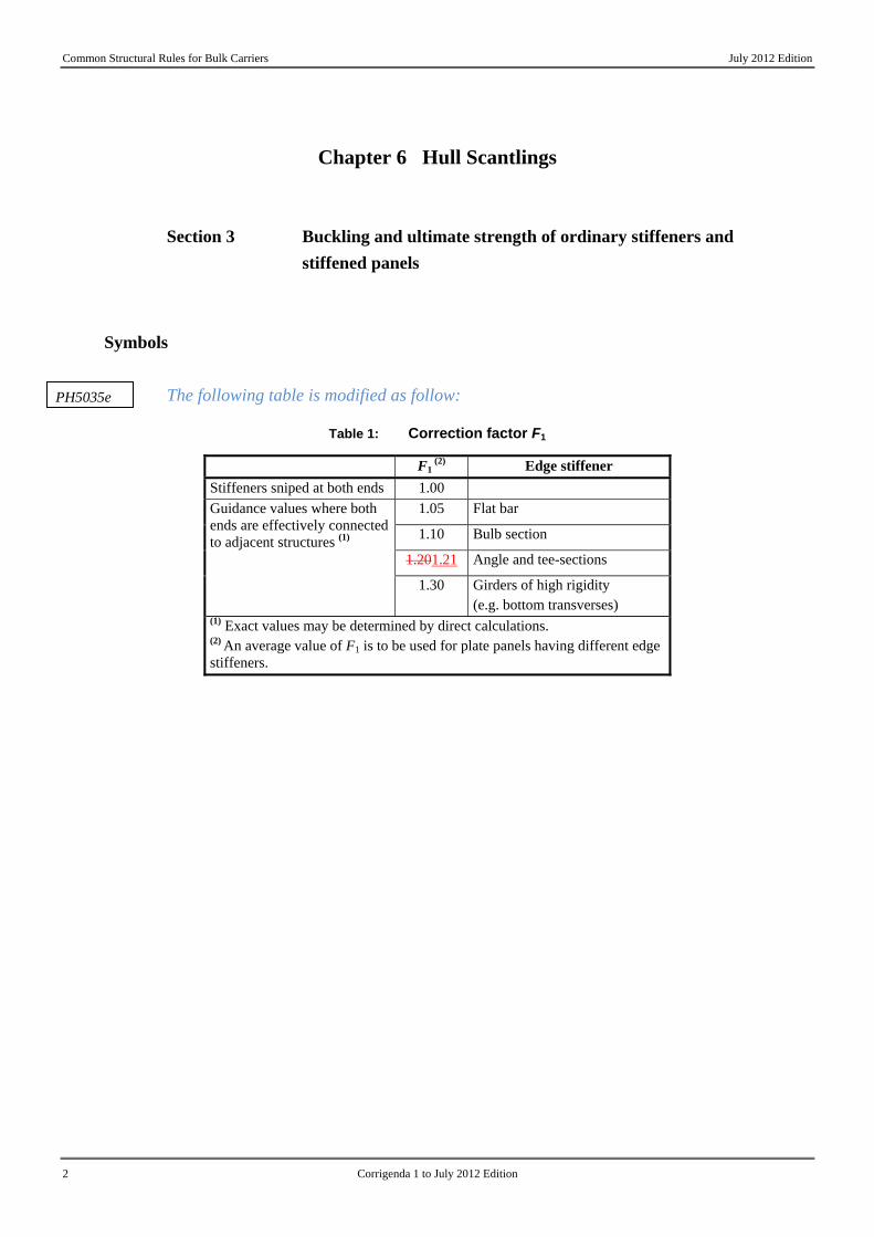
The following table is modified as follow:
Table 1: Correction factor F1
F1 (2) Edge stiffener
Stiffeners sniped at both ends 1.00 1.05 Flat bar
1.10 Bulb section
1.201.21 Angle and tee-sections
Guidance values where both ends are effectively connected to adjacent structures (1)
1.30 Girders of high rigidity (e.g. bottom transverses)
(1) Exact values may be determined by direct calculations. (2) An average value of F1 is to be used for plate panels having different edge stiffeners.
PH5035e
Common Structural Rules for Bulk Carriers July 2012 Edition
Corrigenda 1 to July 2012 Edition 3
Chapter 11 Construction and Testing
Section 3 Testing of Compartments
2 Testing Method
2.3 Hose Testing
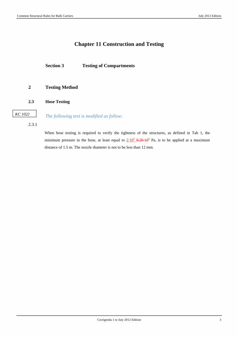
The following text is modified as follow:
2.3.1
When hose testing is required to verify the tightness of the structures, as defined in Tab 1, the
minimum pressure in the hose, at least equal to 2·105 0.20·105 Pa, is to be applied at a maximum
distance of 1.5 m. The nozzle diameter is not to be less than 12 mm.
KC 1022

Common Structural Rules for Bulk Carriers July 2012 Edition
4 Corrigenda 1 to July 2012 Edition
Chapter 13 Ships in Operation, Renewal Criteria
Section 1 Maintenance of Class
1 General
1.1 Application
The following requirement is deleted and replaced by term “void”:
1.1.2 Void
This Chapter is intended to provide Owners, companies performing thickness measurements and
Society’s Surveyors with a uniform procedure in order to fulfil rule requirements for thickness
measurements. In particular, it will enable all the above-mentioned parties to carry out:
• the planning and preparation
• the determination of extent and location
• the analysis
of the thickness measurements.
The following requirement is deleted and replaced by term “void”:
1.1.3 Void
This Chapter also takes into account specific requirements for thickness measurements relevant to
close-up surveys within the scope of the Enhanced Survey Program (ESP) of single side skin bulk
carriers and double side skin bulk carriers.
1.2 Definitions
The following requirement is added:
1.2.3 Deck zone
The deck zone includes all the following items contributing to the hull girder strength above the
horizontal strake of the topside tank or above the level corresponding to 0.9D above the base line if
there is no topside tank:
• strength deck plating
PH11007
PH11007
PH11007

Common Structural Rules for Bulk Carriers July 2012 Edition
Corrigenda 1 to July 2012 Edition 5
• deck stringer
• sheer strake
• side shell plating
• top side tank sloped plating, including horizontal and vertical strakes
• longitudinal stiffeners connected to the above mentioned platings.
The following requirement is added:
1.2.4 Bottom zone
The bottom zone includes the following items contributing to the hull girder strength up to the upper
level of the hopper sloping plating or up to the inner bottom plating if there is no hopper tank:
• keel plate
• bottom plating
• bilge plate
• bottom girders
• inner bottom plating
• hopper tank sloping plating
• side shell plating
• longitudinal stiffeners connected to the above mentioned platings.
The following requirement is added:
1.2.5 Neutral axis zone
The neutral axis zone includes the plating only of the items between the deck zone and the bottom
zone, as for example:
• side shell plating
• inner hull plating, if any.
The following section and its content is deleted:
Section 2 Thickness Measurement and acceptance criteria
Symbols
For symbols not defined in this Section, refer to Ch 1, Sec 4.
PH11007
PH11007
PH11007

Common Structural Rules for Bulk Carriers July 2012 Edition
6 Corrigenda 1 to July 2012 Edition
trenewal : Renewal thickness; Minimum allowable thickness, in mm, below which renewal
of structural members is to be carried out
trenewal = tas_built – tC – tvoluntary_addition
treserve : Reserve thickness; Thickness, in mm, to account for anticipated thickness
diminution that may occur during a survey interval of 2.5 year. (treserve = 0.5 mm)
tC : Corrosion addition, in mm, defined in Ch 3, Sec3
tas_built : As built thickness, in mm, including tvoluntary_addition , if any
tvoluntary_addition : Voluntary thickness addition; Thickness, in mm, voluntarily added as the
Owner’s extra margin for corrosion wastage in addition to tC
tgauged : Gauged thickness, in mm, on one item, i.e average thickness on one item using
the various measurements taken on this same item during periodical ship’s in
service surveys.
1 Application
1.1.1 General
1.1.1
This section provides the following information:
• references to rule requirements and some additional information on the extent of the thickness
measurements to be performed during surveys (see [2.1] and [2.2])
• locations of the measurements for the main parts of the ship (see [2.3])
• how to apply the acceptance criteria (see [3]).
Tables are also given to detail the above items. The sketches are given as an example to illustrate the
requirements.
2 Rule requirements for the extent of measurements and the determination of locations
2.1 General
2.1.1
For the maintenance of class, thickness measurements are required during intermediate and class
renewal surveys and may be required during annual surveys.

Common Structural Rules for Bulk Carriers July 2012 Edition
Corrigenda 1 to July 2012 Edition 7
Tab 1 gives the references to the minimum requirements for thickness measurements related to the
different types of surveys.
Table 1: References to rule requirements related to thickness
measurements
Class renewal survey Intermediate survey Annual survey Outside the cargo length area: UR Z7: • systematic measurements and
suspect areas. • where substantial corrosion is
found, the extent of thickness measurements may be increased to the Surveyor’s satisfaction.
Outside the cargo length area: UR Z7: • thickness measurements to be taken
if deemed necessary by the Surveyor.
• where substantial corrosion is found, the extent of thickness measurements may be increased to the Surveyor’s satisfaction.
Outside the cargo length area: UR Z7: • areas of substantial corrosion
identified at previous class renewal or intermediate surveys;
• where substantial corrosion is found, the extent of thickness measurements may be increased to the Surveyor’s satisfaction.
Within the cargo length area: a) single side skin bulk carriers: UR Z10.2: • planning and general
requirements • measurements of elements
subjected to close-up survey • extent of systematic thickness
measurements • according to the different
locations, where substantial corrosion is found
Within the cargo length area: a) single side skin bulk carriers: UR Z10.2: Ships 10 years of age or less: • for cargo holds • for salt ballast tanks • according to the different locations,
where substantial corrosion is foundShips over 10 years of age: • see references given for class
renewal survey • according to the different locations,
where substantial corrosion is found
Within the cargo length area: a) single side skin bulk carriers: UR Z10.2: • for cargo holds and when deemed
necessary by the Surveyor • for salt ballast tanks and when
deemed necessary by the Surveyor • according to the different locations,
where substantial corrosion is found
b) double side skin bulk carriers: UR Z10.5: • planning and general
requirements • measurements of elements
subjected to close-up survey • extent of systematic thickness
measurements • according to the different
locations, where substantial corrosion is found
b) double side skin bulk carriers: UR Z10.5: Ships 10 years of age or less: • for cargo holds • for salt ballast tanks • according to the different locations,
where substantial corrosion is foundShips over 10 years of age: • see references given for class
renewal survey • according to the different locations,
where substantial corrosion is found
b) double side skin bulk carriers: UR Z10.5: • for cargo holds and when deemed
necessary by the Surveyor • for salt ballast tanks and when
deemed necessary by the Surveyor • according to the different locations,
where substantial corrosion is found
2.2 Class renewal survey
2.2.1
The thickness measurements required by the Rules consist of:
• systematic thickness measurements in order to assess the global and local strength of the ship
• thickness measurements as indicated in the program of close-up survey
• measurements of elements considered as suspect areas

Common Structural Rules for Bulk Carriers July 2012 Edition
8 Corrigenda 1 to July 2012 Edition
• additional measurements on areas determined as affected by substantial corrosion.
2.2.2
For the determination of close-up surveys and relevant thickness measurements as well as the areas
considered as suspect areas, reference is to be made to the relevant Sections of the following IACS
Unified Requirements:
• for the hull structure and piping systems in way of cargo holds, cofferdams, pipe tunnels, void
spaces, fuel oil tanks within the cargo length area and all ballast tanks:
• UR Z10.2 “Hull surveys of single skin bulk carriers”
• UR Z10.5 “Hull surveys of double skin bulk carriers”
• for the remainder of the ship outside the cargo length area:
• UR Z7.
2.3 Number and locations of measurements
2.3.1 Number of measurements
Considering the extent of thickness measurements as required by the Rules and indicated in [2.1] and
[2.2], the locations of the points to be measured are given for the most important items of the
structure.
2.3.2 Locations of measurements
Tab 2 provides explanations and/or interpretations for the application of those requirements indicated
in the Rules which refer to both systematic thickness measurements related to the calculation of global
hull girder strength and specific measurements connected to close-up surveys.
Fig 1 to Fig 5 are provided to facilitate the explanations and/or interpretations given in Tab 2, to show
typical arrangements of single side skin bulk carriers and double side skin bulk carriers.
Table 2: Interpretations of rule requirements for the locations
and number of points to be measured
Item Interpretation Figure reference Selected plates on deck, tank top, bottom, double bottom and wind-and-water area
«Selected» means at least a single point on one out of three plates, to be chosen on representative areas of average corrosion
All deck, tank top and bottom plates and wind-and-water strakes
At least two points on each plate to be taken either at each 1/4 extremity of plate or at representative areas of average corrosion
Transverse section Single side skin bulk carrier: A transverse section includes all longitudinal members such as plating, longitudinals and girders at the deck, side, bottom; inner bottom and hopper side plating, longitudinal bulkhead and bottom
Fig 1 for single and double side skin bulk carriers

Common Structural Rules for Bulk Carriers July 2012 Edition
Corrigenda 1 to July 2012 Edition 9
Item Interpretation Figure reference plating in top wing tanks. Double side skin bulk carrier: A transverse section includes all longitudinal members such as plating, longitudinals and girders at the deck, sides, bottom, inner bottom, hopper sides, inner sides and top wing inner sides.
Cargo hold hatch covers and coamings Fig 2
Selected internal structure such as floors and longitudinals, transverse frames, web frames, deck beams, girders
The internal structural items to be measured in each space internally surveyed are to be at least 10% outside the cargo length area
Transverse section of deck plating outside line of cargo hatch openings
Two single points on each deck plate (to be taken either at each 1/4 extremity of plate or at representative areas of average corrosion) between the ship sides and hatch coamings in the transverse section concerned
Selected areas of all deck plating inside line of hatch openings
«Selected» means at least a single point on one out of three plates, to be chosen on representative areas of average corrosion «All deck plating» means at least two points on each plate to be taken either at each 1/4 extremity of plate or at representative areas of average corrosion
Extent of areas is shown in UR Z10.2 for single side skin bulk carriers and UR Z10.5 for double side skin bulk carriers
Selected side shell frames in cargo holds for single side skin bulk carriers
25% of frames: one out of four frames should preferably be chosen throughout the cargo hold length on each side «Selected frames» means at least 3 frames on each side of cargo holds
Extent of areas is shown in UR Z10.2 for single side skin bulk carriers. Locations of points are given in Fig 3 for single side skin bulk carriers
Transverse frame in double skin tank Fig 1
Transverse bulkheads in cargo holds Includes bulkhead plating, stiffeners and girders, including internal structure of upper and lower stools, where fitted. Two selected bulkheads: one is to be the bulkhead between the two foremost cargo holds and the second may be chosen in other positions
Areas of measurements are shown in UR Z10.2 for single side skin bulk carriers and UR Z10.5 for double side skin bulk carriers. Locations of points are given in Fig 4.
One transverse bulkhead in each cargo hold
This means that the close-up survey and related thickness measurements are to be performed on one side of the bulkhead; the side is to be chosen based on the outcome of the overall survey of both sides. In the event of doubt, the Surveyor may also require (possibly partial) close-up survey on the other side
Areas of measurements are shown in UR Z10.2 for single side skin bulk carriers and UR Z10.5 for double side skin bulk carriers. Locations of points are given in Fig 4.
Transverse bulkheads in one topside/side ballast tank
The ballast tank is to be chosen based on the history of ballasting among those prone to have the most severe conditions
Locations of points are given in Fig 5

Common Structural Rules for Bulk Carriers July 2012 Edition
10 Corrigenda 1 to July 2012 Edition
Item Interpretation Figure reference Transverse webs in ballast tanks One of the representative tanks of each type
(i.e. topside or hopper or side tank) is to be chosen in the forward part
Extent of areas is shown in UR Z10.2 for single side skin bulk carriers and in UR Z10.5 for double side skin bulk carriers. Locations of points are given in Fig 3.
Single side bulk carriers
Double side bulk carrier
Note: Measurements are to be taken on both port and starboard sides of the selected transverse section.
Figure 1: Transverse section of bulk carrier

Common Structural Rules for Bulk Carriers July 2012 Edition
Corrigenda 1 to July 2012 Edition 11
1 1 1
L/4 L/2 3L/4
2
2
2
2
3
1
2 3
50 mm
$ $ $ $
Notes :
1. Three sections at L/4, L/2, 3L/4 of hatch cover length, including:
• one measurement of each hatch cover plate and skirt plate
• measurements of adjacent beams and stiffeners
• one measurement of coaming plates and coaming flange, each side
2. Measurements of both ends of hatch cover skirt plate, coaming plate and coaming flange
3. One measurement of one out of three hatch coaming brackets and bars, on both sides and both ends
Figure 2: Locations of measurements on hatch covers and coamings

Common Structural Rules for Bulk Carriers July 2012 Edition
12 Corrigenda 1 to July 2012 Edition
Note : The gauging pattern for web plating is to be a three point pattern for zones A, C and D, and a two point
pattern for zone B (see figure). The gauging report is to reflect the average reading. The average reading is to be
compared with the allowable thickness. If the web plating has general corrosion then this pattern is to be
expanded to a five point pattern.
Figure 3: Locations of measurements on structural members in cargo holds and ballast
tanks of single side skin bulk carriers
Case without stoolsCase with stools
BB
A - A
B - B
A
A
Note: Measurements to be taken in each shaded area as per views A - A and B – B

Common Structural Rules for Bulk Carriers July 2012 Edition
Corrigenda 1 to July 2012 Edition 13
Figure 4: Locations of measurements on cargo hold transverse bulkheads
Note: Measurements to be taken in each vertical section as per view A - A
Figure 5: Locations of measurements on transverse bulkheads of topside, hopper, double
hull and double bottom tanks
3. Acceptance Criteria
3.1 Definitions
3.1.1 Deck zone
The deck zone includes all the following items contributing to the hull girder strength above the
horizontal strake of the topside tank or above the level corresponding to 0.9D above the base line if
there is no topside tank:
• strength deck plating
• deck stringer
• sheer strake

Common Structural Rules for Bulk Carriers July 2012 Edition
14 Corrigenda 1 to July 2012 Edition
• side shell plating
• top side tank sloped plating, including horizontal and vertical strakes
• longitudinal stiffeners connected to the above mentioned platings.
3.1.2 Bottom zone
The bottom zone includes the following items contributing to the hull girder strength up to the upper
level of the hopper sloping plating or up to the inner bottom plating if there is no hopper tank:
• keel plate
• bottom plating
• bilge plate
• bottom girders
• inner bottom plating
• hopper tank sloping plating
• side shell plating
• longitudinal stiffeners connected to the above mentioned platings.
3.1.3 Neutral axis zone
The neutral axis zone includes the plating only of the items between the deck zone and the bottom
zone, as for example:
• side shell plating
• inner hull plating, if any
3.2 Local strength criteria
3.2.1 Items for the local strength criteria
The items to be considered for the local strength criteria are those of the deck zone, the bottom zone
and the neutral axis zone, as defined in [0], and the additional following items:
• hatch coaming plating
• hatch coaming brackets
• hatch cover top plating
• hatch cover skirt plating
• hatch cover stiffeners
• transverse bulkheads plating
• transverse bulkheads stiffener web
• transverse bulkheads stiffener flange
• side shell frames web
• side shell frames flange
• side shell frames brackets
Common Structural Rules for Bulk Carriers July 2012 Edition
Corrigenda 1 to July 2012 Edition 15
• web of topside and hopper tank web frames
• flange of topside and hopper tank web frames
• floors plating and stiffeners
• forward and aft peak bulkheads plating
• forward and aft peak bulkheads stiffener web
• forward and aft peak bulkheads stiffener flange
• stringers and girders.
3.2.2 Renewal thickness for corrosion other than local corrosion
For each item, steel renewal is required when the gauged thickness tgauged is less than the renewal
thickness, as specified in the following formula:
tgauged < trenewal,
Where the gauged thickness tgauged is such as:
trenewal < tgauged < trenewal + treserve
coating applied in accordance with the coating manufacturer’s requirements or annual gauging may be
adopted as an alternative to the steel renewal. The coating is to be maintained in good condition.
3.2.3 Renewal thickness for local corrosion
If pitting intensity in an area where coating is required, according to Ch 3, Sec 5, is higher than 15%
(see Fig 6), thickness measurements are to be performed to check the extent of pitting corrosion. The
15% is based on pitting or grooving on only one side of a plate.
In cases where pitting is exceeding 15%, as defined above, an area of 300 mm or more, at the most
pitted part of the plate, is to be cleaned to bare metal and the thickness is to be measured in way of the
five deepest pits within the cleaned area. The least thickness measured in way of any of these pits is to
be taken as the thickness to be recorded.
The minimum remaining thickness in pits, grooves or other local areas as defined in Ch 13, Sec1,
[1.2.1] is to be greater than:
• 75% of the as-built thickness, in the frame and end brackets webs and flanges
• 70% of the as-built thickness, in the side shell, hopper tank and topside tank plating attached to the
each side frame, over a width up to 30 mm from each side of it,
without being greater than trenewal.

Common Structural Rules for Bulk Carriers July 2012 Edition
16 Corrigenda 1 to July 2012 Edition
Figure 6: Pitting intensity diagrams (from 5% to 25% intensity)
3.3 Global strength criteria
3.3.1 Items for the global strength criteria
The items to be considered for the global strength criteria are those of the deck zone, the bottom zone
and the neutral axis zone, as defined in [0].
3.3.2 Renewal thickness
The global strength criteria is defined by the assessment of the bottom zone, deck zone and neutral
axis zone, as detailed below.
a) bottom zone and deck zone:
The current hull girder section modulus determined with the thickness measurements is not to be less
than 90% of the section modulus calculated according to Ch 5, Sec 1 with the gross offered
thicknesses.
Alternatively, the current sectional areas of the bottom zone and of the deck zone which are the sum
of the gauged items area of the considered zones, are not to be less than 90% of the sectional area of
the corresponding zones determined with the gross offered thicknesses.
b) neutral axis zone:

Common Structural Rules for Bulk Carriers July 2012 Edition
Corrigenda 1 to July 2012 Edition 17
The current sectional area of the neutral axis zone, which is the sum of the gauged platings area of this
zone, is not to be less than 85% of the gross offered sectional area of the neutral axis zone.
If the actual wastage of all items, of a given transverse section, which contribute to the hull girder
strength is less than 10% for the deck and bottom zones and 15% for the neutral axis zone, the global
strength criteria of this transverse section is automatically satisfied and its checking is no more
required.
The following section and its content are added (in addition, references are updated):
Section 2 Acceptance criteria
Symbols
For symbols not defined in this Section, refer to Ch 1, Sec 4.
trenewal : Renewal thickness; Minimum allowable thickness, in mm, below which renewal
of structural members is to be carried out
trenewal = tas_built – tC – tvoluntary_addition
treserve : Reserve thickness; Thickness, in mm, to account for anticipated thickness
diminution that may occur during a survey interval of 2.5 year. (treserve = 0.5 mm)
tC : Corrosion addition, in mm, defined in Ch 3, Sec3
tas_built : As built thickness, in mm, including tvoluntary_addition , if any
tvoluntary_addition : Voluntary thickness addition; Thickness, in mm, voluntarily added as the
Owner’s extra margin for corrosion wastage in addition to tC
tgauged : Gauged thickness, in mm, on one item, i.e average thickness on one item using
the various measurements taken on this same item during periodical ship’s in
service surveys.
PH11007

Common Structural Rules for Bulk Carriers July 2012 Edition
18 Corrigenda 1 to July 2012 Edition
1. Local strength criteria
1.1 Application
1.1.1
The items to be considered for the local strength criteria are those defined in UR Z10.2 for single side
skin bulk carriers and UR Z10.5 for double side skin bulk carriers.
1.2 Renewal thickness for corrosion other than local corrosion
1.2.1
For each item, steel renewal is required when the gauged thickness tgauged is less than the renewal
thickness, as specified in the following formula:
tgauged < trenewal,
Where the gauged thickness tgauged is such as:
trenewal < tgauged < (trenewal + treserve)
coating applied in accordance with the coating manufacturer’s requirements or annual gauging may be
adopted as an alternative to the steel renewal. The coating is to be maintained in good condition.
1.3 Renewal thickness for local corrosion
1.3.1
If pitting intensity in an area where coating is required, according to Ch 3, Sec 5, is higher than 15%
(see Fig 1), thickness measurements are to be performed to check the extent of pitting corrosion. The
15% is based on pitting or grooving on only one side of a plate.
In cases where pitting is exceeding 15%, as defined above, an area of 300 mm or more, at the most
pitted part of the plate, is to be cleaned to bare metal and the thickness is to be measured in way of the
five deepest pits within the cleaned area. The least thickness measured in way of any of these pits is to
be taken as the thickness to be recorded.
The minimum remaining thickness in pits, grooves or other local areas as defined in Ch 13, Sec 1,
[1.2.1] is to be greater than:
• 75% of the as-built thickness, in the frame and end brackets webs and flanges
• 70% of the as-built thickness, in the side shell, hopper tank and topside tank plating attached to the
each side frame, over a width up to 30 mm from each side of it,
without being greater than trenewal.

Common Structural Rules for Bulk Carriers July 2012 Edition
Corrigenda 1 to July 2012 Edition 19
Figure 1: Pitting intensity diagrams (from 5% to 25% intensity)
1.4 Global strength criteria
1.4.1 Items for the global strength criteria
The items to be considered for the global strength criteria are those of the deck zone, the bottom zone
and the neutral axis zone, as defined in Ch 13, Sec 1, [1.2].
1.4.2 Renewal thickness
The global strength criteria is defined by the assessment of the bottom zone, deck zone and neutral
axis zone, as detailed below.
a) bottom zone and deck zone:
The current hull girder section modulus determined with the thickness measurements is not to be less
than 90% of the section modulus calculated according to Ch 5, Sec 1 with the gross offered
thicknesses.
Alternatively, the current sectional areas of the bottom zone and of the deck zone which are the sum
of the gauged items area of the considered zones, are not to be less than 90% of the sectional area of
the corresponding zones determined with the gross offered thicknesses.
b) neutral axis zone:
The current sectional area of the neutral axis zone, which is the sum of the gauged platings area of this
zone, is not to be less than 85% of the gross offered sectional area of the neutral axis zone.

Common Structural Rules for Bulk Carriers July 2012 Edition
20 Corrigenda 1 to July 2012 Edition
If the actual wastage of all items, of a given transverse section, which contribute to the hull girder
strength is less than 10% for the deck and bottom zones and 15% for the neutral axis zone, the global
strength criteria of this transverse section is automatically satisfied and its checking is no more
required.


![有効 ClassNK テクニカルインフォメーション一覧表 · PDF fileダウンロード ClassNK Technical Information 2018/01/12 13:01:24] 有効 ClassNK](https://img.dokumen.tips/doc/110x75/5a7989e37f8b9a197e8c89fa/-classnk-.jpg)