Embed Size (px)
Citation preview

A – 23AUTOMATIONDIRECT
C-more Operator Panels Selection & Specifications
www.automat iond i rec t . com oorr http ://c -more .automat iond i rec t . com
C-more Selection Guide & SpecificationsModel 8” TFT color
w/ full features10” TFT color
w/ full features12” TFT color
w/ full features15” TFT color
w/ full featuresSpecificationPart Number EA7-T8C EA7-T10C EA7-T12C EA7-T15C
Price <---> <---> <---> <--->
Display Actual Size and Type 8.4" TFT color 10.4" TFT color 12.1" TFT color 15.0" TFT color
Color Scale 65,536 colors
Display Viewing Area 6.73" x 5.05"[170.9 mm x 128.2 mm]
8.31" x 6.24"[211.2 mm x 158.4 mm]
9.47" x 7.62"[240.6 mm x 184.5 mm]
11.97" x 8.98"[304.1 mm x 228.1 mm]
Screen Pixels 640 x 480 (VGA) 800 x 600 (SVGA) 1024 x 768 (XGA)
Display Brightness 300 cd/m22 (NITS) 270 cd/m22 (NITS) 260 cd/m22 (NITS) 220 cd/m22 (NITS)
LCD Panel Dot Pitch 0.267 mm x 0.267 mm 0.33 mm x 0.33 mm 0.267 mm x 0.267 mm 0.297 mm x 0.297 mm
Backlight Average Lifetime* Approximately 50,000 hours
Backlight User Replaceable Yes - Part Number EA-xx-BULB, xx = panel size
Touch Panel Type Analog Resistive (10-bit resolution, 1024 x 1024 touch area) Analog Resistive (12-bit resolution, 4096 x 4096 touch area)
CPU Type 32-Bit RISC CPU (400 MHz) 32-Bit RISC CPU (400 MHz) Plus Graphic Accelerator Chip
Battery Replaceable battery – ADC Part # D2-BAT-1 (Manufacturer Part # CR2354)
System Memory SDRAM 32 MBytes SDRAM 64 MBytes
System Flash Memory FLASH 32 MBytes FLASH 64 MBytes
Backup Memory (SRAM) Control data backup memory (SRAM) 256 KBytes
Logging Data Memory CompactFlash Memory Card p/n EA-FLASH-128MB, industrial grade, high speed (Optional)or USB Pen Drive p/n SDCZ4-512-A10 (Optional)
Number of Screens Up to 999 – limited by available project memory (10 MBytes) Up to 999 – limited by available project memory (40 MBytes)
Realtime Clock Built into panel (PLC clock is still accessible if available)
Calendar – Month/Day/Year Yes - battery backup
Screen Saver Yes, backlight turns off after a 30–1500 minute adjustable time, or can be disabled
Serial PLC Interface Serial PLC Port: RS-232C/422/485 15-Pin D-sub (female)
USB Port – Type B Download/Program – USB Port – type B
USB Port – Type A Port for USB device options – type A
Ethernet Port Ethernet 10/100 Base-T
Audio Line Out Audio Line Out, 1 Volt rms, stereo – requires amplifier and speaker(s)
CF Card – Slot #1 Optional: CompactFlash Memory Card p/n EA-FLASH-128MB, industrial grade, high speed, CF slot #1 located on top side of touch panel.
Expansion Assembly(p/n EA-EXP-OPT)
Optional: Use the CF Card Interface Module p/n EA-CF-IF in the right slot of the Expansion Assembly for installing CF card - Slot #2.The left slot of the Expansion Assembly is for future options.
Supply Power 24 VDC, -15%, +20% (20.4–28.8 VDC operating range)(Use an AC Power Adapter, p/n EA-AC, to power the touch panel from a 100-240 VAC, 50/60 Hz. power source.)
Power Consumption 15 W @ 24 VDC 17 W @ 24 VDC 20 W @ 24 VDC 33 W @ 24 VDC
Recommended Input Fuse 3.0 A DC slow blow
Operating Temperature 0 to 50 °C (32 to 122 °F)
Storage Temperature –20 to +60 °C (–4 to +140 °F)
Humidity 10–85% RH, non-condensing
Noise Immunity Noise voltage: 1000 Vp-p, Pulse width: 1 µs, Rise time: 1 ns
Withstand Voltage 1000 VDC for 1 minute, between DC power supply input terminal and safety ground
Insulation Resistance Over 20 M� between DC power supply input terminal and safety ground
Vibration IEC61131-2 compliant, 10–57 Hz: 0.075 mm amplitude, 57–150 Hz 1.0 G: 10 sweep cycles per axis on each of 3 mutually perpendicular axes
Shock 15 G peak, 11 ms duration, 2 shocks per axis, on 3 mutually perpendicular axes
Enclosure NEMA 4/4X , IP-65 (When mounted correctly. For indoor use only.)
Agency Approvals UL, cUL, CE
Dimensions 8.748" x 10.894" x 2.053"[222.2 mm x 276.7 mm x 52.1 mm]
10.669" x 13.661" x 2.079"[271.0 mm x 347.0 mm x 52.8 mm]
11.024" x 13.366" x 2.075"[280.0 mm x 339.5 mm x 52.7 mm]
13.000" x 16.748" x 2.048"[330.2 mm x 425.4 mm x 52.0 mm]
Weight 2.60 lb. [1,180 g] 3.55 lb. [1,610 g] 4.59 lb. [2,080 g] 7.01 lb. [3,180 g]
* NOTE: The backlight average lifetime is defined as the average usage time it takes before the brightness becomes 50% of the initial brightness. The lifetime of the back-light depends on the ambient temperature. The lifetime will decrease under low or high temperature usage.
C-more Operator Panels Specifications
1 - 8 0 0 - 6 3 3 - 0 4 0 5A – 32 AUTOMATIONDIRECT
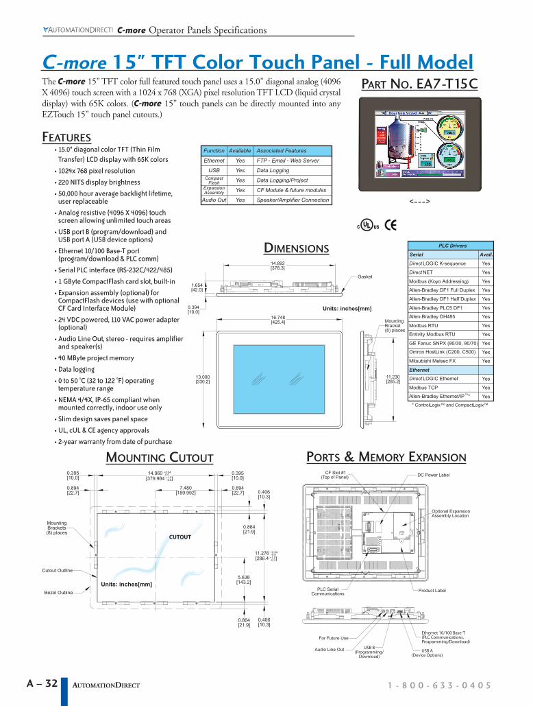
C-more 15" TFT Color Touch Panel - Full Model
14.960 +0.04
[379.984 +1.0]-0.0
-0.0
11.276 +0.04
[286.4 +1.0]
CUTOUT
Bezel Outline
Cutout Outline
Units: inches[mm]
-0.0
-0.0
0.395[10.0]
0.894[22.7]
7.480[189.992]
0.395[10.0]
0.894[22.7] 0.406
[10.3]
0.864[21.9]
5.638[143.2]
0.406[10.3]
0.864[21.9]
MountingBrackets(8) places
The C-more 15” TFT color full featured touch panel uses a 15.0" diagonal analog (4096X 4096) touch screen with a 1024 x 768 (XGA) pixel resolution TFT LCD (liquid crystaldisplay) with 65K colors. (C-more 15” touch panels can be directly mounted into anyEZTouch 15” touch panel cutouts.)
Units: inches[mm]16.748[425.4]
13.000[330.2]
14.892[378.3]
1.654[42.0]
0.394[10.0]
11.230[285.2]
Gasket
MountingBracket(8) places
PART NO. EA7-T15C
FEATURES• 15.0" diagonal color TFT (Thin Film
Transfer) LCD display with 65K colors
• 1024x 768 pixel resolution
• 220 NITS display brightness
• 50,000 hour average backlight lifetime,user replaceable
• Analog resistive (4096 X 4096) touchscreen allowing unlimited touch areas
• USB port B (program/download) andUSB port A (USB device options)
• Ethernet 10/100 Base-T port(program/download & PLC comm)
• Serial PLC interface (RS-232C/422/485)
• 1 GByte CompactFlash card slot, built-in
• Expansion assembly (optional) forCompactFlash devices (use with optionalCF Card Interface Module)
• 24 VDC powered, 110 VAC power adapter(optional)
• Audio Line Out, stereo - requires amplifierand speaker(s)
• 40 MByte project memory
• Data logging
• 0 to 50 °C (32 to 122 °F) operatingtemperature range
• NEMA 4/4X, IP-65 compliant whenmounted correctly, indoor use only
• Slim design saves panel space
• UL, cUL & CE agency approvals
• 2-year warranty from date of purchase
DC Power Label
Product Label
USB A(Device Options)
USB B(Programming/
Download)
For Future Use
Audio Line Out
PLC SerialCommunications
Ethernet 10/100 Base-T(PLC Communications,Programming/Download)
CF Slot #1(Top of Panel)
Optional ExpansionAssembly Location
PORTS & MEMORY EXPANSION
DIMENSIONS
MOUNTING CUTOUT
<--->
ULC USR
Function Available Associated Features
Ethernet
USBCompact
FlashExpansionAssembly
Audio Out
Yes
Yes
Yes
Yes
Yes
FTP - Email - Web Server
Data Logging
Data Logging/Project
CF Module & future modules
Speaker/Amplifier Connection
PLC Drivers
Serial
Direct LOGIC K-sequence
Avail.
Yes
Yes
Yes
Yes
Direct NET
Allen-Bradley DF1 Full Duplex
Allen-Bradley DF1 Half Duplex
Allen-Bradley PLC5 DF1
Allen-Bradley DH485
Modbus RTU
Entivity Modbus RTU
GE Fanuc SNPX (90/30, 90/70)
Omron HostLink (C200, C500)
Mitsubishi Melsec FX
Ethernet
Direct LOGIC Ethernet
Modbus TCP
Allen-Bradley Ethernet/IP™*
Yes
Yes
Yes
Yes
Yes
Yes
Yes
Yes
Yes
Yes
* ControlLogix™ and CompactLogix™
YesModbus (Koyo Addressing)
A – 33AUTOMATIONDIRECT
C-more Operator Panels Communications
www.automat iond i rec t . com oorr http ://c -more .automat iond i rec t . com
For Future Use
Audio Line Out,stereo, 1 Volt rms,3.5mm Mini Jack
(Amplifier Required)
USB Port - Type BProgramming/Download USB Port - Type A
USB Device Options
Ethernet 10/100 Base-TPLC Communications,
Programming/Download
1 821 3 42 1
3 4
8 1
15 9
Pin Signal
1 Frame GND
TXD (232C)
RXD (232C)
Vcc
2
3
4
5 Logic GND
Pin Signal Pin Signal
6 LE
CTS (232C)
RTS (232C)
RXD+ (422/485)
7
8
9
10 RXD– (422/485)
11 TXD+ (422/485)
TXD– (422/485)
Term. Resistor
do not use
12
13
14
15 do not use
Pin Signal
1 TD+
TD–
RD+
do not use
2
3
4
Pin Signal
5 do not use
RD–
do not use
do not use
6
7
8Pin Signal
1 do not use
D–
D+
GND
2
3
4
Pin Signal
1 Vbus
D–
D+
GND
2
3
4
ShieldShell
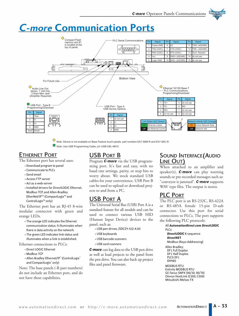
PLC Serial Communications
Network Activity LED (Orange)
On Active Network Data
Network IdleOff
Link Status LED (Green)
On Ethernet Linked
No Ethernet Comm.Off
Bottom View
Note: Device is not available on Base Feature touch panels, part numbers EA7-S6M-R and EA7-S6C-R.
Compact Flashmemory slot #1is located at thetop of panel.
Note: Use USB Programming Cable, p/n USB-CBL-AB15.
ETHERNET PORTThe Ethernet port has several uses:
• Download program to panel• Communicate to PLCs• Send email• Access FTP server• Act as a web-server• Installed drivers for DirectLOGIC Ethernet,
Modbus TCP, and Allen-BradleyEtherNet/IPTM (CompactLogixTM andControlLogixTM only)
The Ethernet port has an RJ-45 8-wiremodular connector with green andorange LEDs.
• The orange LED indicates the Ethernetcommunication status. It illuminates whenthere is data activity on the network.
• The green LED indicates link status andilluminates when a link is established.
Ethernet connections to PLCs:• Direct LOGIC Ethernet• Modbus TCP• Allen-Bradley Ethernet/IP™ (ControlLogix™
and CompactLogix™ only)
Note: The base panels (-R part numbers)do not include an Ethernet port, and donot have these capabilities.
SOUND INTERFACE(AUDIOLINE OUT)When attached to an amplifier andspeaker(s), C-more can play warningsounds or pre-recorded messages such as:"conveyor is jammed". C-more supportsWAV type files. The output is stereo.
PLC PORTThe PLC port is an RS-232C, RS-422Aor RS-485A female 15-pin D-subconnector. Use this port for serialconnections to PLCs. The port supportsthe following PLC protocols:
All AutomationDirect.com DirectLOGICPLCs:
DirectLOGIC K-sequenceDirectNETModbus (Koyo Addressing)
Allen Bradley:DF1 Full DuplexDF1 Half DuplexPLC5 DF1DH485
MODBUS RTUEntivity MODBUS RTUGE Fanuc SNPX (90/30, 90/70)Omron HostLink (C200, C500)Mitsubishi Melsec FX
USB PORT BProgram C-more via the USB program-ming port. It's fast and easy, with nobaud rate settings, parity, or stop bits toworry about. We stock standard USBcables for your convenience. USB Port Bcan be used to upload or download proj-ects to and from a PC.
USB PORT AThe Universal Serial Bus (USB) Port A is astandard feature for all models and can beused to connect various USB HID(Human Input Device) devices to thepanel, such as:
• USB pen drives, (SDCZ4-512-A10)
• USB keyboards
• USB barcode scanners
• USB card scanners
C-more can log data to the USB pen driveas well as load projects to the panel fromthe pen drive. You can also back up projectfiles and panel firmware.
C-more Communication Ports

C-more Operator Panels Communications
1 - 8 0 0 - 6 3 3 - 0 4 0 5A – 34 AUTOMATIONDIRECT
PLC Compatibility TablePLC /Network Model Protocols
Allen-Bradley
MicroLogix 1000/1200/1500, SLC 500, 5/01, /02, /03 DH485/AIC/AIC+
MicroLogix 1000,1200 and 1500 DF1 Half Duplex; DF1 Full Duplex
SLC 5/03, /04, /05 DF1 Half Duplex; DF1 Full Duplex
PLC-5 DF1 Full Duplex
Ethernet/IP Ethernet/IP (ControlLogix™ and CompactLogix™ only) EtherNet/IP™
Modbus TCP/IP Modbus TCP/IP devices Modbus TCP/IP
GE 90/30 and 90/70 SNPX
Mitsubishi FX Series FX, Direct
Modicon 984 CPU, Quantum 113 CPU, AEG Modicon Micro Series 110CPU: 311-xx, 411-xx, 512-xx, 612-xx Modbus RTU
Omron C200, C500 Host Link
DirectLOGIC
DL05/DL06
K-Sequence
DDiirreecctt NNEETT
MODBUS (Koyo addressing)
H0-ECOM/H0-ECOM100 DDiirreecctt LLOOGGIICC Ethernet
DL105 K-Sequence
DL205
D2-230 K-Sequence
D2-240K-Sequence
DDiirreecctt NNEETT
D2-250/D2-250-1/D2-260
K-Sequence
DDiirreecctt NNEETT
MODBUS (Koyo addressing)
D2-240/D2-250-1/D2-260Using DCM
DDiirreecctt NNEETT
MODBUS (Koyo addressing)
H2-ECOM/H2-ECOM100 DDiirreecctt LLOOGGIICC Ethernet
DL305
D3-330/330P(Requires the use of a DataCommunications Unit)
DDiirreecctt NNEETT
D3-340 DDiirreecctt NNEETT
D3-350
K-Sequence
DDiirreecctt NNEETT
MODBUS (Koyo addressing)
D3-350 DCMDDiirreecctt NNEETT
MODBUS (Koyo addressing)
DL405
D4-430K-Sequence
DDiirreecctt NNEETT
D4-440K-Sequence
DDiirreecctt NNEETT
D4-450
K-Sequence
DDiirreecctt NNEETT
MODBUS (Koyo addressing)
All with DCMDDiirreecctt NNEETT
MODBUS (Koyo addressing)
H4-ECOM/H4-ECOM100 DDiirreecctt LLOOGGIICC Ethernet
H2-WinPLC (Think & Do) Live V5.2 or later and Studio any version
Think & Do MODBUS RTU(serial port)
H2-WinPLC (Think & Do) Live V5.5.1 or later andStudio V7.2.1 or later
Think & Do MODBUS TCP/IP(Ethernet port)
CableDescription
CablePart Number Price
DDiirreecctt LLOOGGIICC PLC RJ-12 port,DL05, DL06, DL105, DL205,D3-350, D4-450 &H2-WinPLC (RS-232C)
EA-2CBL <--->
DDiirreecctt LLOOGGIICC (VGA Style)15-pin port, DL06, D2-250(250-1), D2-260 (RS-232C)
EA-2CBL-1 <--->
DDiirreecctt LLOOGGIICC PLC RJ-11 port,D3-340 (RS-232C) EA-3CBL <--->
DDiirreecctt LLOOGGIICC DL405 PLC 15-pinD-sub port, DL405 (RS-232C) EA-4CBL-1 <--->
DDiirreecctt LLOOGGIICC PLC 25-pin D-subport, DL405, D3-350, DL305 DCUand all DCM’s (RS-232C)
EA-4CBL-2 <--->
Allen-Bradley MicroLogix 1000,1200 & 1500 (RS-232C)
EA-MLOGIX-CBL <--->
Allen-Bradley SLC 5-03/04/05DF1 port (RS-232C)
EA-SLC-232-CBL <--->
Allen-Bradley PLC-5DF1 port (RS-232C)
EAPLC5-232-CBL <--->
Allen-Bradley SLC 500DH485 port (RS-232C) EA-DH485-CBL <--->
GE 90/30 and 90/7015-pin D-sub port (RS-422A) EA-90-30-CBL <--->
MITSUBISHI FX Series 25-pin port(RS-422A) EA-MITSU-CBL <--->
MITSUBISHI FX Series8-pin mini-DIN (RS-422A)
EA-MITSU-CBL-1 <--->
OMRON C200, C500 (RS-232C) EA-OMRON-CBL <--->
NOTE: EZTouch serial PLCcommunication cables arecompatible with C-moretouch panels.
EA-2CBL
C-more PLC Communication Protocols & Cables
EA-2CBL-1
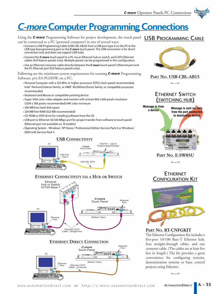
Using the C-more Programming Software for project development, the touch panelcan be connected to a PC (personal computer) in one of several ways:
• Connect a USB Programming Cable (USB-CBL-AB15) from a USB port type A on the PC to theUSB type B programming port on the C-more touch panel. The USB connection is for directconnection only and does not support USB hubs.
• Connect the C-more touch panel to a PC via an Ethernet hub or switch, and CAT5 Ethernetcables (full feature panels only). Multiple panels can be programmed in this configuration.
• Use an Ethernet crossover cable directly between the C-more touch panel’s Ethernet port andthe PC Ethernet port (full feature panels only).
Following are the minimum system requirements for running C-more ProgrammingSoftware, p/n EA-PGMSW, on a PC:
• Personal Computer with a 333 MHz or higher processor (CPU) clock speed recommended;Intel® Pentium/Celeron family, or AMD® K6/Athlon/Duron family, or compatible processorrecommended
• Keyboard and Mouse or compatible pointing device• Super VGA color video adapter and monitor with at least 800 x 600 pixels resolution
(1024 x 768 pixels recommended) 64K color minimum• 300 MB free hard-disk space• 128 MB free RAM (512 MB recommended)• CD-ROM or DVD drive for installing software from the CD• USB port or Ethernet 10/100 Mbps port for project transfer from software to touch panel
(Ethernet port not available on -R models)• Operating System - Windows® XP Home / Professional Edition Service Pack 2 or Windows®
2000 with Service Pack 4
A – 35AUTOMATIONDIRECT
C-more Operator Panels PC Connections
www.automat iond i rec t . com oorr http ://c -more .automat iond i rec t . com
C-moreTouch Panel
(Bottom View)
EthernetPort
Ethernet CAT5Cable - Crossover
EthernetPort
PC
10010/
Uplink Port
LNKACT/
+1
LNKACT/ 10010/
PWR –PWR
LNKACT/ 10010/
ACT/
10010/
10/ACT/
LNK
PWR
23
LNK100
E–SW05U
EthernetHub or Switch10/100 Base-T
C-moreTouch Panel
(Bottom View)
EthernetPort
Ethernet CAT5Cable - Straight-thru
EthernetPort
PC
C-moreTouch Panel
USB Port – Type BProgramming/Download
USB Port –Type A
PC
USB-CBL-AB15
USB CONNECTIVITY
ETHERNET CONNECTIVITY VIA A HUB OR SWITCH
ETHERNET DIRECT CONNECTION
PART NO. RT-CNFGKITThe Ethernet Configuration Kit includes afive-port 10/100 Base-T Ethernet hub,four straight-through cables, and onecrossover cable. (The cables are at least fivefeet in length.) The kit provides a greatconvenience for configuring systems,demonstration systems or basic controlprojects using Ethernet.
Message in froma device
Message is sent out onlyfrom the port connected
to destination device
PART NO. E-SW05U
ETHERNET SWITCH(SWITCHING HUB)
ETHERNETCONFIGURATION KIT
USB PROGRAMMING CABLE
PART NO. USB-CBL-AB15
C-more Computer Programming Connections
<--->
<--->
<--->

C-more Operator Panels Power Connection
1 - 8 0 0 - 6 3 3 - 0 4 0 5A – 36 AUTOMATIONDIRECT
PROVIDING POWER TO THE TOUCH PANEL• Connect a dedicated 24 VDC switching power supply rated for a minimum of 1.5 Amps to the DC connector
on the rear of the C-more touch panel. Connect the ground terminal to a proper equipment ground.
• or install a C-more AC Power Adapter (EA-AC) to the rear of the touch panel and connect an AC volt-age source of 100-240 VAC, 50/60Hertz, to its AC connector.
• then turn on the power source and check the LED status indicators on the rear of the C-more touchpanel for proper operation.
100 - 240 VAC50/60 Hz
PWR
CPU
TxD
RxDBATT
IOlOl–PLC
Power LED (Green)
On Power On
Power OffOff
Serial TxD/RxD LED (Green)
On Comm. is active
No communicationOff
CPU Status LED (Green, Orange & Red)
Off Power Off
Normal – CPU Run StateGreen
Red Memory Error
Operating System not foundBlinkingRed
BlinkingOrange LCD Backlight failure
Rear View
C-more LED Status Indicators
AC WIRING
WARNING: To minimize the riskof potential safety problems, you should followall applicable local and national codes thatregulate the installation and operation of yourequipment. These codes vary from area to areaand it is your responsibility to determine whichcodes should be followed, and to verify that theequipment, installation, and operation are incompliance with the latest revision of thesecodes.
Equipment damage or serious injury to personnelcan result from the failure to follow all applicablecodes and standards. We do not guarantee theproducts described in this publication are suitablefor your particular application, nor do we assumeany responsibility for your product design, installa-tion, or operation.
If you have any questions concerning the instal-lation or operation of this equipment, or if youneed additional information, please call us at1-800-633-0405 or 770-844-4200.
This publication is based on information thatwas available at the time it was printed. At Automationdirect.com® we constantly striveto improve our products and services, so wereserve the right to make changes to the prod-ucts and/or publications at any time withoutnotice and without obligation. This publicationmay also discuss features that may not be avail-able in certain revisions of the product.
C-more Power Connection Wiring
PWR
CPU
BATT
NOTUsed
24 VDC; -15%, +20%(20.4 - 28.8 VDC)
+
–
GNDEquipmentGround
24V
Dedicatedpower supplyrecommended
Recommended Fuse 3 A slow blow
DC WIRING
AC POWER
ADAPTER
EA-ACRecommended Power Supply:
AutomationDirect Part No. PS24-050D