Embed Size (px)
Citation preview
Extension Bulletin 434
C • pUS UBRI\1 IES
GuidelinL.:.:.--'·e----· s for the Installation, Maintenance,
and Analysis of a Pipeline
Milking System R. D. Appleman, R. J. Farnsworth, J. W. Mudge,
J. 0. Hanson, and R. L. Sieber
AGRICULTURAL EXTENSION SERVICE • UNIVERSITY OF MINNESOTA
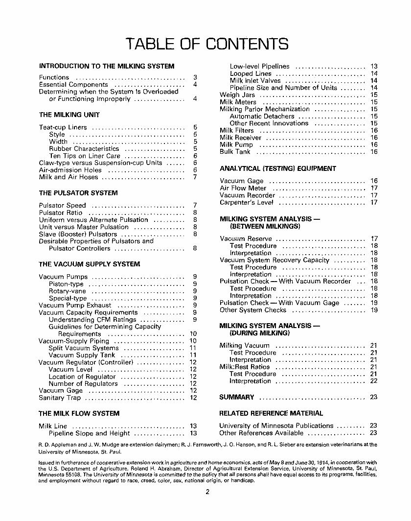
TABLE OF CONTENTS INTRODUCTION TO THE MILKING SYSTEM
Functions . . . . . . . . . . . . . . . . . . . . . . . . . . . . . . . . . . 3 Essential Components . . . . . . . . . . . . . . . . . . . . . . 4 Determining when the System Is Overloaded
or Functioning Improperly . . . . . . . . . . . . . . . . 4
THE MILKING UNIT
Teat-cup Liners . . . . . . . . . . . . . . . . . . . . . . . . . . . . . 5 Style . . . . . . . . . . . . . . . . . . . . . . . . . . . . . . . . . . . . 5 Width . . . . . . . . . . . . . . . . . . . . . . . . . . . . . . . . . . . 5 Rubber Characteristics . . . . . . . . . . . . . . . . . . . 5 Ten Tips on Liner Care . . . . . . . . . . . . . . . . . . . 6
Claw-type versus Suspension-cup Units . . . . . . 6 Air-admission Holes . . . . . . . . . . . . . . . . . . . . . . . . 6 Milk and Air Hoses . . . . . . . . . . . . . . . . . . . . . . . . . . 7
THE PULSATOR SYSTEM
Pulsator Speed . . . . . . . . . . . . . . . . . . . . . . . . . . . . . 7 Pulsator Ratio . . . . . . . . . . . . . . . . . . . . . . . . . . . . . . 8 Uniform versus Alternate Pulsation . . . . . . . . . . 8 Unit versus Master Pulsation . . . . . . . . . . . . . . . . 8 Slave (Booster) Pulsators . . . . . . . . . . . . . . . . . . . . 8 Desirable Properties of Pulsators and
Pulsator Controllers . . . . . . . . . . . . . . . . . . . . . . 8
THE VACUUM SUPPLY SYSTEM
Vacuum Pumps . . . . . . . . . . . . . . . . . . . . . . . . . . . . . 9 Piston-type . . . . . . . . . . . . . . . . . . . . . . . . . . . . . . 9 Rotary-vane . . . . . . . . . . . . . . . . . . . . . . . . . . . . . 9 Special-type . . . . . . . . . . . . . . . . . . . . . . . . . . . . . 9
Vacuum Pump Exhaust . . . . . . . . . . . . . . . . . . . . . 9 Vacuum Capacity Requirements . . . . . . . . . . . . . 9
Understanding CFM Ratings . . . . . . . . . . . . . . 9 Guidelines for Determining Capacity
Requirements . . . . . . . . . . . . . . . . . . . . . . . . 10 Vacuum-Supply Piping . . . . . . . . . . . . . . . . . . . . . . 10
Split Vacuum Systems . . . . . . . . . . . . . . . . . . . 11 Vacuum Supply Tank . . . . . . . . . . . . . . . . . . . . 11
Vacuum Regulator (Controller) . . . . . . . . . . . . . . . 12 Vacuum Level . . . . . . . . . . . . . . . . . . . . . . . . . . . 12 Location of Regulator . . . . . . . . . . . . . . . . . . . . 12 Number of Regulators . . . . . . . . . . . . . . . . . . . 12
Vacuum Gage .............................. 12 Sanitary Trap . . . . . . . . . . . . . . . . . . . . . . . . . . . . . . . 12
THE MILK FLOW SYSTEM
Milk Line . . . . . . . . . . . . . . . . . . . . . . . . . . . . . . . . . . . 13 Pipeline Slope and Height . . . . . . . . . . . . . . . . 13
Low-level Pipelines . . . . . . . . . . . . . . . . . . . . . . 13 Looped Lines . . . . . . . . . . . . . . . . . . . . . . . . . . . . 14 Milk Inlet Valves ......................... 14 Pipeline Size and Number of Units . . . . . . . . 14
Weigh Jars . . . . . . . . . . . . . . . . . . . . . . . . . . . . . . . . . 15 Milk Meters . . . . . . . . . . . . . . . . . . . . . . . . . . . . . . . . 15 Milking Parlor Mechanization . . . . . . . . . . . . . . . . 15
Automatic Detachers . . . . . . . . . . . . . . . . . . . . . 15 Other Recent Innovations . . . . . . . . . . . . . . . . 15
Milk Filters . . . . . . . . . . . . . . . . . . . . . . . . . . . . . . . . . 16 Milk Receiver . . . . . . . . . . . . . . . . . . . . . . . . . . . . . . . 16 Milk Pump ................................. 16 Bulk Tank . . . . . . . . . . . . . . . . . . . . . . . . . . . . . . . . . . 16
ANALYTICAL (TESTING) EQUIPMENT
Vacuum Gage . . . . . . . . . . . . . . . . . . . . . . . . . . . . . . 16 Air Flow Meter . . . . . . . . . . . . . . . . . . . . . . . . . . . . . 17 Vacuum Recorder . . . . . . . . . . . . . . . . . . . . . . . . . . . 17 Carpenter's Level . . . . . . . . . . . . . . . . . . . . . . . . . . . 17
MILKING SYSTEM ANALYSIS(BETWEEN MILKINGS)
Vacuum Reserve . . . . . . . . . . . . . . . . . . . . . . . . . . . . 17 Test Procedure . . . . . . . . . . . . . . . . . . . . . . . . . . 18 Interpretation . . . . . . . . . . . . . . . . . . . . . . . . . . . . 18
Vacuum System Recovery Capacity . . . . . . . . . . 18 Test Procedure .. .. .. .. .. . .. .. .. . .. . .. . . . 18 Interpretation . . . . . . . . . . . . . . . . . . . . . . . . . . . . 18
Pulsation Check- With Vacuum Recorder ... 18 Test Procedure . . . . . . . . . . . . . . . . . . . . . . . . . . 18 Interpretation . . . . . . . . . . . . . . . . . . . . . . . . . . . . 18
Pulsation Check-With Vacuum Gage ....... 19 Other System Checks ....................... 19
MILKING SYSTEM ANALYSIS(DURING MILKING)
Milking Vacuum . . . . . . . . . . . . . . . . . . . . . . . . . . . . 21 Test Procedure . . . . . . . . . . . . . . . . . . . . . . . . . . 21 Interpretation . . . . . . . . . . . . . . . . . . . . . . . . . . . . 21
Milk:Rest Ratios . . .. . . . .. . . . . .. . .. . . . . . . . . . . 21 Test Procedure . . . . . . . . . . . . . . . . . . . . . . . . . . 21 Interpretation . . . . . . . . . . . . . . . . . . . . . . . . . . . . 22
SUMMARY ................................. 23
RELATED REFERENCE MATERIAL
University of Minnesota Publications . . . . . . . . . 23 Other References Available . . . . . . . . . . . . . . . . . . 23
R. D. Appleman and J. W. Mudge are extension dairymen; R. J. Farnsworth, J. 0. Hanson, and R. L. Sieber are extension veterinarians at the University of Minnesota, St. Paul.
Issued in furtherance of cooperative extension work in agriculture and home economics, acts of May 8 and June 30, 1914, in cooperation with the U.S. Department of Agriculture. Roland H. Abraham, Director of Agricultural Extension Service, University of Minnesota, St. Paul, Minnesota 55108. The University of Minnesota is committed to the policy that all persons shall have equal access to its programs, facilities, and employment without regard to race, creed, color, sex, national origin, or handicap.
2

INTRODUCTION TO THE MILKING SYSTEM
To achieve high levels of milk production, the dairyman must use good milking techniques and a machine that will milk cows efficiently and without discomfort. Continued use of faulty, improperly installed, or poorly maintained milking equipment can cause a mild to severe irritation or stress of sensitive teat and udder tissue.
It is the purpose of this publication to explain the functions and components of a milking system and to provide a procedure to use in analyzing whether or not the milking system is performing properly.
FUNCTIONS
The conventional milking machine performs two basic functions:
(1) It imposes a controlled vacuum on the end of the teat to open the teat or~fice and provide the differential pressure (suction) necessary for milk flow.
(2) It massages the teat intermittently to provide
Figure 1. The relationship between malfunctioning milk machine and mastitis.
High vacuum
Large bore liners
stimulation and prevent blood congestion in the teat end.
These two functions must be performed by a properly designed and comfortable liner (inflation). The milking machine may influence the development of mastitis in the following ways:
(1) Damages or removes the teat's natural protective barrier (keratin), allowing the teat ends or internal linings of the teat to become injured and prone to infection.
(2) Permits a backflow of milk through the teat opening during the milking process, resulting in a transfer of mastitis causing organisms to enter the teat. These organisms may originate in another quarter (through the milk) or from exterior contamination (unclean teat and udder surfaces).
The general concept that illustrates the role of the milking machine in controlling mastitis is illustrated in figure 1.
Inadequate milk line
Undersized milkline
slope\ I Flooded milkline
~ J} Wide milk Fast Flooded ~ Fluctuating ~
M A s T
rest ratio ~ milking r::;> teatcups ~ vacuum ~
E/ I 1 milkers Inadequate Too much
milk line lift Small bore
milk tubes
3
vacuum supply
I T I s
ESSENTIAL COMPONENTS
There are four essential components of a mechanical milking system (figure 2).
The milking unit is that part of the machine which is suspended from the cow, performs the milking operation, and receives the milk. It includes the teat-cup assembly, claw or suspension cup, and the connecting air and milk tubes.
The pulsation system includes the pulsator which controls the liner action by introducing vacuum and atmospheric pressure intermittently into the chamber between the liner and the teat-cup shell. It also involves any pipe or hoses that transmit the alternating air-vacuum force to the teat cup.
The vacuum supply system includes the vacuum pump that provides a source of vacuum to the end of the teat to cause milk flow, supplies the energy to activate the liner and massage the teat, and moves milk through the system.
In milking machine terminology, vacuum is air at approximately one-half atmosphere of pressure. To maintain vacuum stability; air must be removed constantly at a rate equal to the sum of all air admissions. The quantity of air entering the controller is equal to the vacuum reserve of the system.
One branch of the vacuum supply leads to the sanitary trap and milk receiver jar separating the
vacuum supply and milk-flow systems. The other branch goes directly to the cow stalls where the pulsators are attached.
The milk flow system includes all hoses, pipes, and containers for conveying the product. The bulk tank normally is not considered a part of the milking system. An exception is any system that employs a vacuum tank and does not use a receiver jar to separate milk from vacuum.
The milk-flow system is of sanitary construction and conveys the milk and air from the teat cups to the bulk tank. When properly installed, the milk-flow system should maintain a reasonably constant and stable vacuum from the sanitary trap to each milking unit on the system.
DETERMINING WHEN THE SYSTEM IS OVERLOADED OR FUNCTIONING IMPROPERL V
A milking system may be overloaded or functioning improperly when any of the following occur:
(1) Milking units fall off. If one unit falls off, do all units drop shortly thereafter?
(2) Vacuum fluctuates severely. Milk hoses that constantly kick violently indicate fluctuating vacuum. This may be the result of either excessively long milk hoses or, in some cases, extremely fast-milking cows.
Vacuum Supply Milk Flow Pulsator Milking Unit
• COMPONENTS FOR MECHANICAL MILKING
Figure 2. Four essential components of a pipeline milking system.
4
(3) Milk lines flood. Does the milk enter the receiver jar in spurts? Is there excessive foaming?
(4) Flow of milk from the claw to the milk pipeline is unsteady.
(5) Recovery of vacuum to the operating level after an air leak is slow.
(6) Teat ends are irritated andfor abnormal.
(7) Milking is slow. Any of these conditions call for a reevaluation of
the milking system. Unless corrections are made, a consistently high level of subclinical mastitis usually will result. Prolonged use of equipment in this condition generally results in more clinical cases of mastitis.
THE MILKING UNIT
TEAT-CUP LINERS (INFLATIONS)
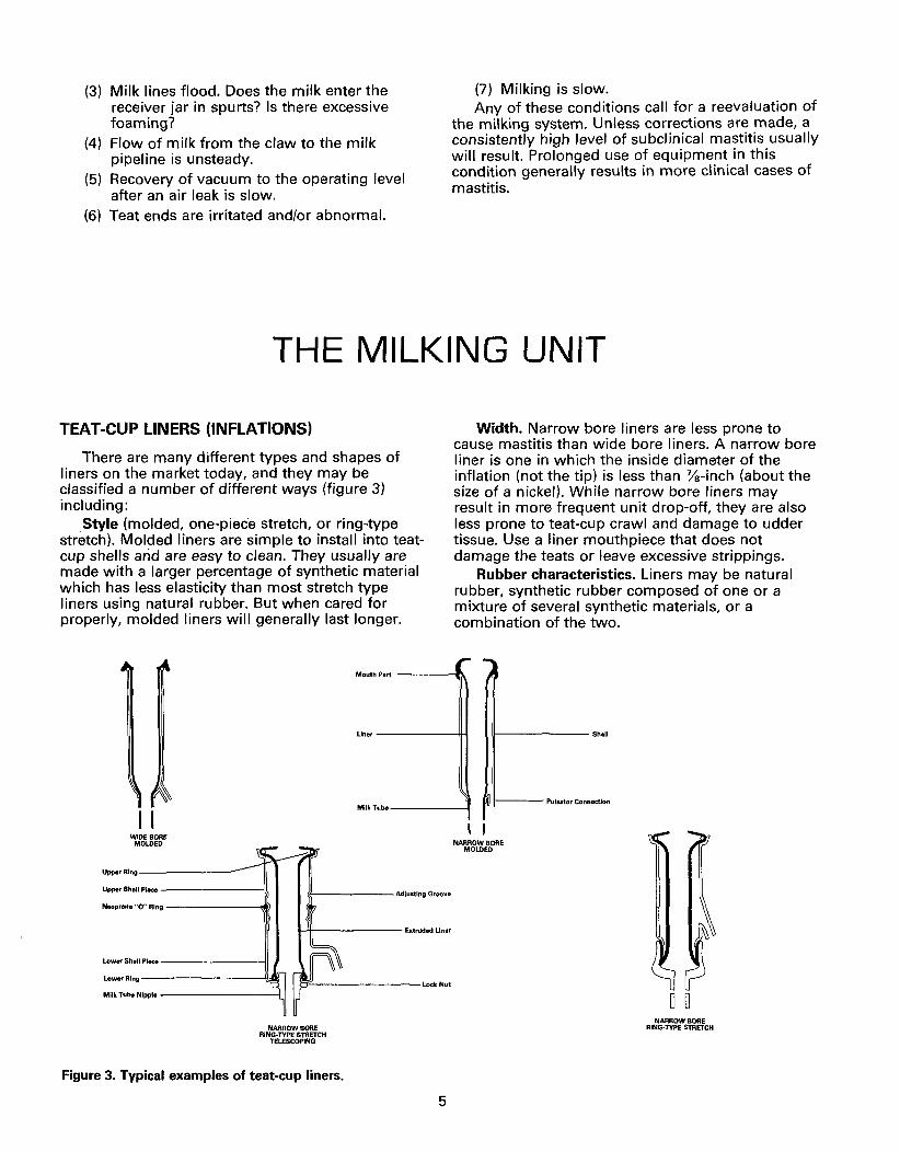
There are many different types and shapes of liners on the market today, and they may be classified a number of different ways (figure 3) including:
Style (molded, one-piec·e stretch, or ring-type stretch). Molded liners are simple to install into teatcup shells arid are easy to clean. They usually are made with a larger percentage of synthetic material which has less elasticity than most stretch type liners using natural rubber. But when cared for properly, molded liners will generally last longer.
Width. Narrow bore liners are less prone to cause mastitis than wide bore liners. A narrow bore liner is one in which the inside diameter of the inflation (notthe tip) is less than "Ya-inch (about the size of a nickel). While narrow bore liners may result in more frequent unit drop-off, they are also less prone to teat-cup crawl and damage to udder tissue. Use a liner mouthpiece that does not damage the teats or leave excessive strippings.
Rubber characteristics. Liners may be natural rubber, synthetic rubber composed of one or a mixture of several synthetic materials, or a combination of the two.
Mouth Part ---Ill.
I I WIDE BORE
MOLDED
Upper Ring--------
Upper Shell Piece ------11
Neoprene "0" Ring-----~
Lower Shell Piece -------11
LoworRing--------\!;Ol
Milk Tube Nipple-------\
NARROW BORE RING· TYPE STRETCH
TELESCOPING
Figure 3. Typical examples of teat-cup liners.
Liner -----tH If------ Sholl
Milk Tube-----f II--- Pulsator Connection
I I NARROW BORE
MOLD EO
5
0 0 NARROW BORE
RING· TYPE STRETCH
The choice between natural and synthetic rubber for teat-cup liners is not easy. Synthetic rubber liners swell less in the presence of milk fat, are easier to keep clean, withstand stretching, and are less likely to tear.
Probably the best molded liner is one designed for and made with synthetic rubber. The straight liners that operate under high stretch are best made from natural rubber.
Each dairyman should try different liner types or rubber specifications, regardless of cost, to see which performs best for his specific herd and operation. Poorly designed, ill fitting, and worn out liners are a major source of teat irritation. It is important, however, to be sure that the shell and liner of choice are compatible. Also, use of liners from a different company may void the manufacturer's warranty.
Ten Tips on Liner Care: (1) Liners become soft and change shape with
overuse. Adhere to the manufacturer's recommendations on liner use, usually about 1,200 cow milkings for the molcted, synthetic rubber liners and 800 cow milkings for natural rubber liners.
Formula for determining total days of liner use: Recommended liner No. milking life (in days) x units _No. of days to use No. of milkings No cows in set of liners per day x milk Example 1: 2-unit barn, 50 cows in milk, molded liner
1200x 2=2400= 24 days 2 X50 100
Example 2: 4-unit barn, 160 cows in milk, stretch liner 800x 4 =3200= 10 days
2 X 160 320
(2) Always remove liners by pulling straight off the claw, not at an angle. This procedure helps eliminate tears and splits.
(3) Handle the claw assembly (which includes liners) with care. Dropping or hitting the liners against stall partitions, etc. can cause claw cuts or pin holes in the liner milk stem.
(4) Change complete sets-of-4 liners. Cows are quick to notice and react negatively to two different milk: rest variations.
(5) Never set the milking unit aside and allow milk to dry in the liners. Always rinse in cool water, then wash, then rinse again. Avoid a buildup of organic materials including milk fat, protein, and sugar.
(6) Remove the liners from the shell every week to 10 days. Those liners that require a lot of stretch need to be relaxed periodically.
(7) Make sure the liner is not twisted in its shell. This can cause liners to fall off and quarters to not milk out.
(8) Do not store liners near electric motors or in sunlight. Electric motors produce ozone that
6
can cause cracking of the rubber; sunlight shortens the useful life of liners. Do not apply fly spray on liner surfaces.
(9) Prevent water from getting between the shell and liner. This can cause the liner to function improperly. When washing manually with the liner installed in the shell, connect an air tube between the nipples.
(10) Make sure the liner is being used in the shell for which it was designed. The wrong combination may cause a liner to split or collapse incorrectly. Make certain that the liner, when collapsed, can still move freely within the shell.
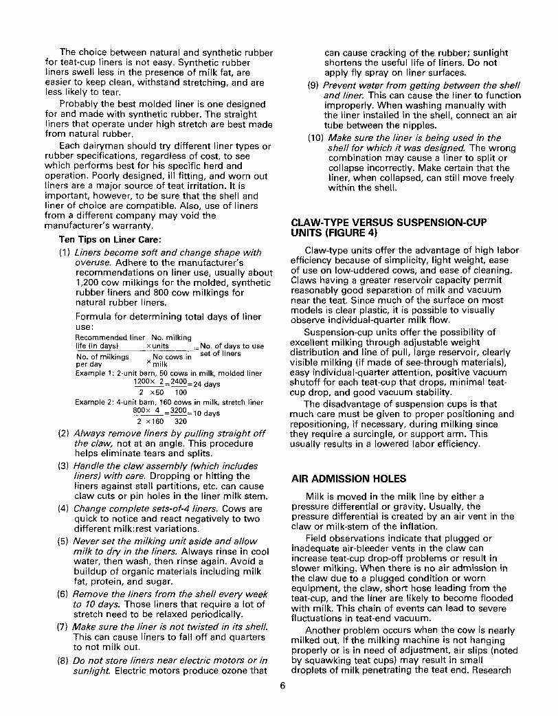
CLAW-TYPE VERSUS SUSPENSION-CUP UNITS {FIGURE 4)
Claw-type units offer the advantage of high labor efficiency because of simplicity, light weight, ease of use on low-uddered cows, and ease of cleaning. Claws having a greater reservoir capacity permit reasonably good separation of milk and vacuum near the teat. Since much of the surface on most models is clear plastic, it is possible to visually observe individual-quarter milk flow.
Suspension-cup units offer the possibility of excellent milking through adjustable weight distribution and line of pull, large reservoir, clearly visible milking (if made of see-through materials), easy individual-quarter attention, positive vacuum shutoff for each teat-cup that drops, minimal teatcup drop, and good vacuum stability.
The disadvantage of suspension cups is that much care must be given to proper positioning and repositioning, if necessary, during milking since they require a surcingle, or support arm. This usually results in a lowered labor efficiency.
AIR ADMISSION HOLES
Milk is moved in the milk line by either a pressure differential or gravity. Usually, the pressure differential is created by an air vent in the claw or milk-stem of the inflation.
Field observations indicate that plugged or inadequate air-bleeder vents in the claw can increase teat-cup drop-off problems or result in slower milking. When there is no air admission in the claw due to a plugged condition or worn equipment, the claw, short hose leading from the teat-cup, and the liner are likely to become flooded with milk. This chain of events can lead to severe fluctuations in teat-end vacuum.
Another problem occurs when the cow is nearly milked out. If the milking machine is not hanging properly or is in need of adjustment, air slips (noted by squawking teat cups) may result in small droplets of milk penetrating the teat end. Research
%" Pulsated Pipe
Short Air Tube
CLAW-TYPE (With Master Pulsation)
Unit Pulsator
Support Arm or Surcingle ~------~~
Pulsator Pipe
SUSPENSION CUP (With Unit Pulsation)
Figure 4. Two types of milking units (claw and suspension cup); two types of pulsation (unit and master).
has shown that air slips increase when either the teat penetrates further into the liner or when the teat cup slips down the teat. When either happens, new quarter infections may occur. Air admission holes in the claw should be checked daily to be sure they have not become plugged.
A recent development is the provision of an air admission inlet in each liner, just below the shell. While results have generally been favorable in that there is less flooding, its success is dependent on having an adequate vacuum reserve since, usually, more air is admitted. In addition, there is concern about more problems with milk rancidity. It is generally recommended that "claw" air inlets be blocked-off when "liner" air-inlets are used. Since the liner air inlets are smaller, they tend to become blocked more easily, and require frequent checking.
MILK AND AIR HOSES
Milk hoses are either synthetic rubber or clear plastic. Rubber has the best flexibility and longer life, but plastic is favored for its visibility. Plastic hoses tend to "crack" more on the ends that are repeatedly placed over pipeline nipples.
Milk hoses should be of the diameter recommended by the equipment manufacturer. A larger milk hose will not improve the milk flow characteristics or vacuum stability in an overhead pipeline, but does benefit low-line systems.
Because some dairymen anticipate having to trim the hose ends, they install excessively long milk hoses. Looping excess hose causes excessive vacuum fluctuation.
Pulsator hoses should be of good quality rubber and approximately the same length as the milk hose. Be sure they "seal" tightly around the pipe nipple at either end of the hose.
THE PULSATOR SYSTEM
The pulsator is an automatic air-vacuum valve that directs atmospheric air into the chamber between the teat-cup liner and the shell, and then withdraws this air by opening a port into the vacuum system. This intermittent air-vacuum state causes the characteristic liner action.
The more common "unit" pulsator operates only one milking unit. A "master" pulsator operates two or more milking units simultaneously.
7
PULSATOR SPEED
Most milking machines perform ideally at pulsator speeds of 45 to 60 pulsations per minute. Faster speeds may not provide adequate teat massage or rest under certain conditions. Faster pulsation tends to deplete the vacuum reserve since each pulsation admits a definite volume of air into the pulsator pipeline.
PULSATOR RATIO
Pulsator ratios total 100 percent and usually range between 50/50 and 70/30. The first number refers to the amount of time the pulsator draws vacuum to open the liner and withdraw milk. The second number indicates the amount of time it admits atmospheric air to collapse the liner and massage the teat.
A 70/30 pulsator ratio milking machine will milk cows faster than a 50/50 machine, all other factors being equal. But it is important to minimize overmilking with the higher ratio machines because more stress is placed on the teat-end- especially at moderately-high vacuum levels (more than 14 inches).
UNIFORM VERSUS ALTERNATE PULSATION
Uniform pulsation machines milk (or rest) all four quarters simultaneously. Alternate pulsation machines milk two quarters while the other two are being massaged or rested. Some brands of machines, equipped with dual pulsators, milk the rear quarters at a different pulsator ratio (e.g., 60/40) than the front quarters (e.g., 50/50).
Alternating pulsation generally maintains a more stable milking vacuum when the system is marginal or inadequate. It also tends to reduce teat-cup crawl with claw-type units. The disadvantage on some types of alternating pulsation systems is that if the equipment malfunctions, it may alter the milking ratio between the opposite sides of the udder. This can result in secondary problems.
UNIT VERSUS MASTER PULSATION (FIGURE 4)
In barns with more than 12 stanchions, properly maintained unit pulsators of the electrically controlled type are more likely to supply an identical pulsator ratio and speed to all cows.
Unit pulsators normally are a part of the portable milking unit. One type is attached to the free end of the pulsator hose, serving the dual purpose of pulsator and automatic stallcock; another type is attached to the claw or suspension cup to avoid long, pulsated hoses.
Unit pulsators may be either dependent or independent in their action. Dependent pulsators are either electromagnetic or electropneumatic, depending upon the electromechanism (timerconverter or timer-pulser) to produce either a lowvoltage electric or pulsated vacuum signal which activates the pulsator at each milking unit. Their primary problem is that unit pulsators are subject to electrical faults in their several circuits.
8
Independent pulsators are the pneumatic types, which are self-acting and which receive their energy from the same vacuum that they pulsate. The main problem with these pulsators is the speed variation possible.
Field observations have shown that some master pulsators are easily overloaded. Generally, the pulsated line should be a %-inch pipe, terminated at each outer stallcock to avoid excess pipe. Automatic drain valves on the pulsator line are desirable but must be checked frequently for proper closing. The number of units that one master pulsator can serve properly is best determined under operating conditions on site. Its performance is generally superior when not more than two units are operated on either side of the master pulsator and all units are located within about 12 feet of the pulsator.
Master pulsators should be fully accessible from floor level or walkways, as they need daily checking and may need speed adjustment during the course of milking. In unheated barns or parlors, it is advisable to install a shielded 25 to 40 watt bulb close to pneumatic pulsators to keep them warm at all times and ready for immediate service.
SLAVE(BOOSTER)PULSATORS
Definite and somewhat snappy pulsator action is desirable. Unit pulsators near the teat-cups give a sharp action by avoiding long, pulsated pipes and hoses which can cause sluggish action due to air friction. Booster pulsators are sometimes used to amplify a weak or sluggish air-vacuum signal into a sharp action near the teat-cups. A modern pulsation system, used in accordance with the manufacturer's instructions and properly maintained, will produce good pulsation without the use of boosters.
DESIRABLE PROPERTIES OF PULSATORS AND PULSATOR CONTROLLERS
Pulsators and their control devices, whether built-in or remote, must be reliable and have a low maintenance requirement. The net result at the teatcup, as evidenced by udder health and recorder graphs, is more important than whether pulsation is pneumatic or electric.
Pulsated vacuum can be influenced by many kinds of pulsator deficiencies, including wear, leaks, sticking parts, plugged ports, and faulty electrical timers and circuits. Pulsators should be checked continuously during milking to detect sticking, air leaks, plugged ports, or abnormal speeds. Be sure that the air inlet ports are inspected and cleaned daily to prevent foreign matter from accumulating and eventually plugging the pulsator.
THE VACUUM SUPPLY SYSTEM
VACUUM PUMPS
Whether the dairy farm has 10 or 1,000 cows, the vacuum pump must produce and deliver the proper vacuum to the milking unit. Vacuum pump performance has improved markedly in the past several years, but a pump does wear out and lose efficiency over time. What's worse, a pump becomes inefficient so gradually that dairymen do not realize when it becomes overloaded.
There are several different kinds of vacuum pumps available- piston, rotary-vane, and specialtypes.
Piston-type. The most common piston-type vacuum pump used for milking is a multicylinder, single-acting, vertical, reciprocating air pump. This pump is rugged, operates at low or moderate speed, and is usually dependable.
Rotary-vane pumps. These are available in highand-low-speed models. The high-speed models (1,750 rpm or higher) remove more air (high cubic feet per minute, or cfm, capacity) for the physical size of the unit. Their disadvantages are undesirable sound level and possibly excessive oil consumption. The low-speed pumps (400 to 800 rpm) have a lower sound level, usually consume less oil, and require little maintenance.
Special-type. These pumps include industrial pumps with rotary principles (turbine, water-sealed, etc.). One such pump uses a centrifugal displacement principle that requires 3 gallons of water per minute. While it has several advantages (no metal-to-metal contact surfaces, not affected by fluids passing through it, low noise level), it has the major disadvantage of requiring considerable volumes of water that must be disposed of. With some brands, water may be recycled to conserve its use. Recycling, however, can have limitations when water hardness is too great.
Rotary pumps will move more air at moderate vacuum than piston pumps of the same horsepower. This means that a rotary pump will make available more "vacuum reserve," give faster recovery, and provide a more stable vacuum when unintentional air admissions occur.
Whenever two or more vacuum pumps are used, they should be connected into a common vacuum tank (header). This assures that only one vacuum level is in effect and that the load is balanced. If two dissimilar pumps are used, each pump will perform to its cfm ability for the existing vacuum level at the pump inlet. The total system capacity, however, may not equal the sum of the two pumps operating
9
independently. Each pump should be connected into the system with a full flow (gate) valve so that one can be removed from the system without influencing the other in event of pump failure.
VACUUM PUMP EXHAUST
The exhaust pipe must be at least as large as the connecting fitting on the pump, preferably one size larger when the exhaust pipe exceeds 8 feet in length or uses two or more elbows. The discharge should end outside the barn to minimize oil accumulation and fumes in the building. Care should be taken to avoid having the discharge directly in front of a compressor's condensing unit.
An air silencer/oil separator attached to the exhaust pipe i::; recommended. One excellent arrangement in common use is a 30-gallon (%barrel) clip-top grease drum buried to within 4-inches of ground level. Cut a round hole in the lid opposite the bung and braze in a pipe nipple for the air inlet. Screw a 2-inch nipple into the bung with a 2-inch "tee" on top for air exhaust. The "tee" discourages anyone from tossing junk into the barrel. Connect the exhaust pipe from the vacuum pump to the bung with a union or flexible sleeve. This permits the clip-top lid to be removed annually, or when needed, for bailing out the accumulated oil and water.
VACUUM CAPACITY REQUIREMENTS
The type of vacuum pump used is not as important as adequate capacity. It is difficult to specify exact air requirements for pipeline milking systems, since this varies greatly depending on: (a) brand and model in use, (b) number of units used, (c) air leakage within a given installation, and (d) operator's milking technique. A beginning step is to understand cubic feet per minute (cfm) ratings.
Understanding cfm ratings. There are two methods used for rating vacuum pumps. They are the American Standard Method (ASME) and the New Zealand Method (NZ}. The American method measures at standard atmospheric pressures and temperatures; the New Zealand method measures the air at 15-inches vacuum. Since the New Zealand method is at twice the volume when compared to the American method, the calculated or observed values are twice as large. Note: A vacuum pump that delivers 30 cfm on the ASME standard will deliver 60 cfm on the NZ standard.
Vacuum pump manufacturers using the ASME system include Chore-Boy, Delaval, Jamesway,
Perfection, TeSa, Universal, and Zero. Those using the NZ method include Bou-Matic, Masport, and Surge.
Field observations have shown that the most satisfactorily operating pipeline milking systems typically used in Minnesota produce about 9 to 12 cfm, American standard (18 to 24 cfm, NZ standard), per milking unit. This volume normally allows sufficient reserve, so there is seldom a major problem even if one unit falls off or is permitted "to draw air" for an extended period.
Note: This recommended standard is more than double that required for "bucket" milking systems. This explains why the addition of a pipeline milking system usually includes the purchase of a larger (or another) vacuum pump. Values for conventional bucket machines are: cfm reserve= 10 ASME (20 NZ) + [No. of units x 2.5 ASME (5 NZ).]
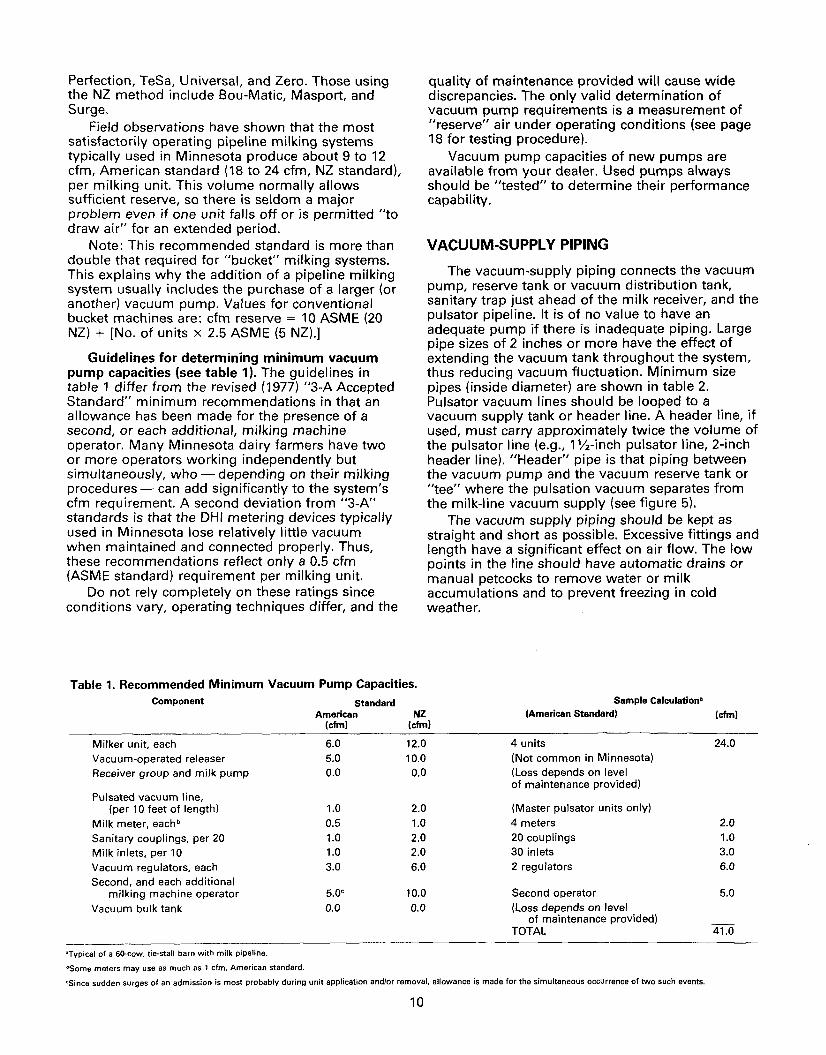
Guidelines for determining minimum vacuum pump capacities (see table 1). The guidelines in table 1 differ from the revised (1977) "3-A Accepted Standard" minimum recommendations in that an allowance has been made for the presence of a second, or each additional, milking machine operator. Many Minnesota dairy farmers have two or more operators working independently but simultaneously, who- depending on their milking procedures- can add significantly to the system's cfm requirement. A second deviation from "3-A" standards is that the DHI metering devices typically used in Minnesota lose relatively little vacuum when maintained and connected properly. Thus, these recommendations reflect only a 0.5 cfm (ASME standard) requirement per milking unit.
Do not rely completely on these ratings since conditions vary, operating techniques differ, and the
quality of maintenance provided will cause wide discrepancies. The only valid determination of vacuum pump requirements is a measurement of "reserve" air under operating conditions (see page 18 for testing procedure).
Vacuum pump capacities of new pumps are available from your dealer. Used pumps always should be "tested" to determine their performance capability.
VACUUM-SUPPL V PIPING
The vacuum-supply piping connects the vacuum pump, reserve tank or vacuum distribution tank, sanitary trap just ahead of the milk receiver, and the pulsator pipeline. It is of no value to have an adequate pump if there is inadequate piping. Large pipe sizes of 2 inches or more have the effect of extending the vacuum tank throughout the system, thus reducing vacuum fluctuation. Minimum size pipes (inside diameter) are shown in table 2. Pulsator vacuum lines should be looped to a vacuum supply tank or header line. A header line, if used, must carry approximately twice the volume of the pulsator line (e.g., 1 %-inch pulsator line, 2-inch header line). "Header" pipe is that piping between the vacuum pump and the vacuum reserve tank or "tee" where the pulsation vacuum separates from the milk-line vacuum supply (see figure 5).
The vacuum supply piping should be kept as straight and short as possible. Excessive fittings and length have a significant effect on air flow. The low points in the line should have automatic drains or manual petcocks to remove water or milk accumulations and to prevent freezing in cold weather.
Table 1. Recommended Minimum Vacuum Pump Capacities. Component
Milker unit, each Vacuum-operated releaser Receiver group and milk pump
Pulsated vacuum line, (per 10 feet of length)
Milk meter, each" Sanitary couplings, per 20 Milk inlets, per 10 Vacuum regulators, each Second, and each additional
milking machine operator Vacuum bulk tank
•Typical of a so-cow, tie-stall barn with milk pipeline.
OSome meters may use as much as 1 cfm, American standard.
Standard American
(cfm)
6.0 5.0 0.0
1.0 0.5 1.0 1.0 3.0
5.0° 0.0
Sample Calculation• NZ (American Standard) (cfm)
(cfm)
12.0 4 units 24.0 10.0 (Not common in Minnesota) 0.0 (Loso; depends on level
of maintenance provided)
2.0 (Master pulsator units only)
1.0 4 meters 2.0 2.0 20 couplings 1.0 2.0 30 inlets 3.0 6.0 2 regulators 6.0
10.0 Second operator 5.0 0.0 (Loss depends on level
of maintenance provided) TOTAL 41.0
'Since sudden surges of an admission is most probably during unit application and/or removal, allowance is made for the simultaneous occurrence of two such events.
10

Table 2. Recommended Minimum Pipe Size for Various Parts of the Vacuum Supply Pipeline.
Number of Minimum Pipeline Size (Inside Diameter) Milking Units Header Pipe Pulsation System Milking Vacuum•
2 1~" 1" 1~" 3 1~" 1~" 1~" 4 2" 1~" 1~" 5 2" 1~" 1Y2' 6 2~" 1~" 2" 7 2~" 1 Y2" 2" 8 2'!12" 2" 2" 9 2W' 2" 2"
10 2~" 2" 2" 11-13 3" 2" 2~"
14 or more 3" 2" 3"
'It is recommended that the main vacuum supply pipeline be the same size as the milk pipeline it supplies.
Adequate opportunity for flushing and cleaning the vacuum pipes with wire burrs should be provided. Instead of 90-degree elbows, pipe tees with one opening plugged may be used frequently to enhance access for cleaning.
Plastic pipe can usually be used to good advantage at less cost than galvanized plumbing. It must, however, be of high quality and not collapse under the vacuums encountered nor be affected by oil and cleaning chemicals. PVC schedule 40 piping or heavier generally is preferred. Bends in plastic pipe should be kept as large as practical; radii of curvature for 11;'2-inch plastic pipe should be at least 4 feet. Note: It is necessary to support plastic pipe
Pulsator Line
Reserve Tank
Automatic L---Orain
Vacuum Pump
Sanitary Trap
Figure 5. General overview of a milking system.
11
more frequently than galvanized pipe. Do not use plastic pipe on exhaust side of pump. It cannot take the heat.
Split vacuum systems. Conventional pipeline milking systems do not need differential vacuums between milk and pulsator lines if the piping and pump sizes are adequate and installed properly. A higher vacuum in the pulsator pipeline tends to cause excessive teat and liner ballooning. Conversely, a higher vacuum in the milk line can prevent complete liner opening except during the period of heavy milk flow. In either case, two different vacuums make the system more complicated and offer a greater possibility of malfunction.
Vacuum supply tank (balance tank, vacuum distribution tank). Vacuum supply tanks usually are recommended unless there is an oversized vacuum supply (header) pipe to which the sanitary trap is connected and which leads directly to a highcapacity vacuum pump. The vacuum supply tank provides a great vacuum source of limited duration. It prevents excessive fluctuation when instantaneous air admission is greater than pump capacity.
The vacuum in the top of the milk receiver extends out through the milk pipeline, through the milk hoses and teat-cups to the teats. This vacuum does the milking and is felt by the cows; therefore, it must be closely stabilized. The vacuum tank should be as close as possible to the sanitary trap ahead of the milk receiver in order to quickly dampen any excess air that enters the milk pipeline.
Pulsator
Milking Unit
Bulk Tank
Vacuum tank capacities of about 5 gallons per milking unit have been of benefit in many barns. Water heater tanks are satisfactory, but it often is necessary to install larger inlets. An automatic drain or handy petcock at the lowest point also is necessary. The 5 gallon per unit thumbrule may not apply in all instances, especially those barns with 10 or more units equipped with an oversized "header" pipe.
Separate inlets for the milk system and pulsator system are desirable, as this further localizes vacuum disturbances to only part of the total system.
VACUUM REGULATOR (CONTROLLER)
The vacuum regulator (controller) is the vacuumlimiting valve that prevents the vacuum level from exceeding a set value by admitting atmospheric air as necessary. The most common types are ball, poppet, or sliding-sleeve valves held in a closed position by deadweight or spring until the vacuum level exceeds the set limit.
With the advent of low-level milk-lines in milking parlors, differences in liner (inflation) resistance to opening, and extreme variation in milking techniques, it is advisable to install a vacuum regulator that may be adjusted easily to best suit the particular operation.
Vacuum level. Constant exposure of the teats to the vacuum levels normally used in milking machines (12 to 15 inches) can cause damage to the teat ends, particularly when the teat-cup liners do not collapse completely (or remain collapsed sufficiently long to provide adequate massage) during each pulsation cycle. This damage is greater at the higher vacuum levels. On the other hand, operating with a low vacuum may "slow" milking and/or increase the "fall-off" problem. Each dairyman is encouraged to experiment with different vacuum levels within the manufacturer's recommended range until he is satisfied that he has the most desirable level for his particular installation and conditions.
Location of regulator. The critical milking vacuum is in the milk receiver jar, since that is the vacuum reaching teat-end. Because of sanitary regulations, the closest the vacuum regulator can be located to the milk receiver jar is on the vacuum pump side of the sanitary trap.
The vacuum supply pipe just ahead of the trap (or in the vacuum supply tank, if it is located close to the milk receiver jar) is an ideal location for the
12
regulator (figure 5). Locating the regulator in this position places it in the milk-room (the cleanest, most dust-free location in the barn) so that it will be observed frequently and cleaned regularly. Many regulators become clogged from oil and dust accumulating on them. A malfunctioning regulator can easily lead to a disastrously high milking vacuum if vacuum pump capacity is adequate.
Number of regulators. The vacuum regulator must have sufficient capacity to balance the cfm capacity of the vacuum pump when only one unit is in operation. All systems should have two regulators to provide a safety valve in the event one regulator should stick or malfunction. Some highcapacity pumps need several regulators to provide enough air inlet to prevent exceeding the preset level. A regulator in the pulsator pipeline is not necessary if the pulsator pipeline is properly joined to the vacuum supply system.
VACUUM GAGE
The common vacuum gage is the mechanicaldial type, calibrated from 0 to 30 inches of mercury measured from atmospheric pressure. The vacuum gage should be located in or near the sanitary trap to reflect the milk-line vacuum. It should not be located in the same pipe fitting as the regulator, or it may not indicate the true operating vacuum.
Additional gages installed in the pulsator line in large stall barns are a convenience for the operators. While pulsator line vacuum measurements are not as meaningful as the milking vacuum, they can assist the operators in spotting a malfunction when milking chores are being accomplished. Gages in opposite ends of the pulsator system in large barns should not vary more than 1 inch from one another. Dial-type gages should be checked regularly for accuracy.
SANITARY TRAP
The sanitary trap separates the milk contact part of the system from the air system, thus preventing contamination by movement of liquid from one to the other. Transparent traps serve as an aid in detecting fluid leaks into the air system (e.g., split liner).
The connecting santary pipe between the trap and the receiver jar must slope continuously downward toward the trap. This will prevent any possibility of reverse flow of minute traces of bacteria-laden milk that may incubate in the connecting pipe for several hours.

THE MILK FLOW SYSTEM
MilK liNE
The milk line conveys milk and air from the milking unit to the receiver where the milk and air are separated. The most common size of milk line in new installations in Minnesota is 2-inch stainlesssteel tubing.
These assemblies and the other milk-flow system components are joined together with sanitary connectors or unions of the hex-nut or clamp-and-gasket type. Welded milk lines are becoming more popular each year. They prevent the air leak, gasket, and turbulence problems of union connections.
Pipeline slope and height. Pipeline slope is a major factor affecting vacuum fluctuations due to milkline flooding. Pipeline height never should exceed 7 feet above the cow's platform and preferably should be much less. A uniform slope of 1% inches per 10 feet of pipeline is recommended. In existing stall barns with level floors, a compromise may be necessary. If milkline height is going to exceed 6% feet because of barn size, a slope of 1 inch per 10 feet of pipeline is satisfactory.
Milk pipelines should not be "high" simply for the convenience of the operator. He can "duck under" when he must cross-over. The reason for keeping pipelines as low as possible is to stabilize the vacuum at the teat end. Each additional foot of
Floor
ACCEPTABLE MILK PIPELINE SUPPORT
-·--TelewoplngPipe ltoellowforugofcelllng)
ACCEPTAillE MILK PIPELINE SUPPORT
'-._ CeiUngflango
Taln.eoplngPlpo -~ttolllllowfor .. gol
.:oiling)
lnlulalionll11M•11m -plpeendhenger
Floor
Figure 6. Examples of milk pipeline support methods.
13
milkline height results in a vacuum drop of nearly %inch when milk flow rate approaches 10 pounds per minute.
The milking pipeline should be supported so that the entire pipeline and all fittings remain in constant position and alignment when assembled. Thus, the pipeline must be supported on posts, columns, or standards permanently secured to the floor, except that in milking parlors the supports may be permanently and solidly secured to the wall of the operator's pit (figure 6).
Support hangers should be fully adjustable vertically and should allow for free horizontal thermal expansion. Support hangers must be insulated to prevent electrolysis of dissimilar metals. Milk pipeline couplings should not be located in sleeves of wall openings.
Wall opening sleeves must be large enough to allow easy removal of pipes. The area between the milk pipe and the sleeve should be protected to prevent the entrance of dust, flies, or other insects into the milk-room.
To prevent incorporation of air in the milk, there should be no risers in the milk pipeline. Any upward slope encountered by the milk moving toward the receiver in a pipeline is considered a riser. Vertical milk pipes which convey only milk (no air) are not considered to be risers.
Low-level pipelines. Low-level pipeline systems, where the milk pipe is at or below udder level, reduce a cause of excessive vacuum fluctuation at the claw or teat-cup. This is because solid slugs of milk must accumulate before milk can be "lifted" vertically.
All new milking parlors should be designed to advantageously utilize low-level lines by sloping the floor in the direction of milk flow and locating the milk-room at a lower elevation to permit the receiver to be installed in the conventional manner. If the terrain is such that a multi-level parlor building is impractical, the milk receiver and pump assembly may be installed in the parlor pit.
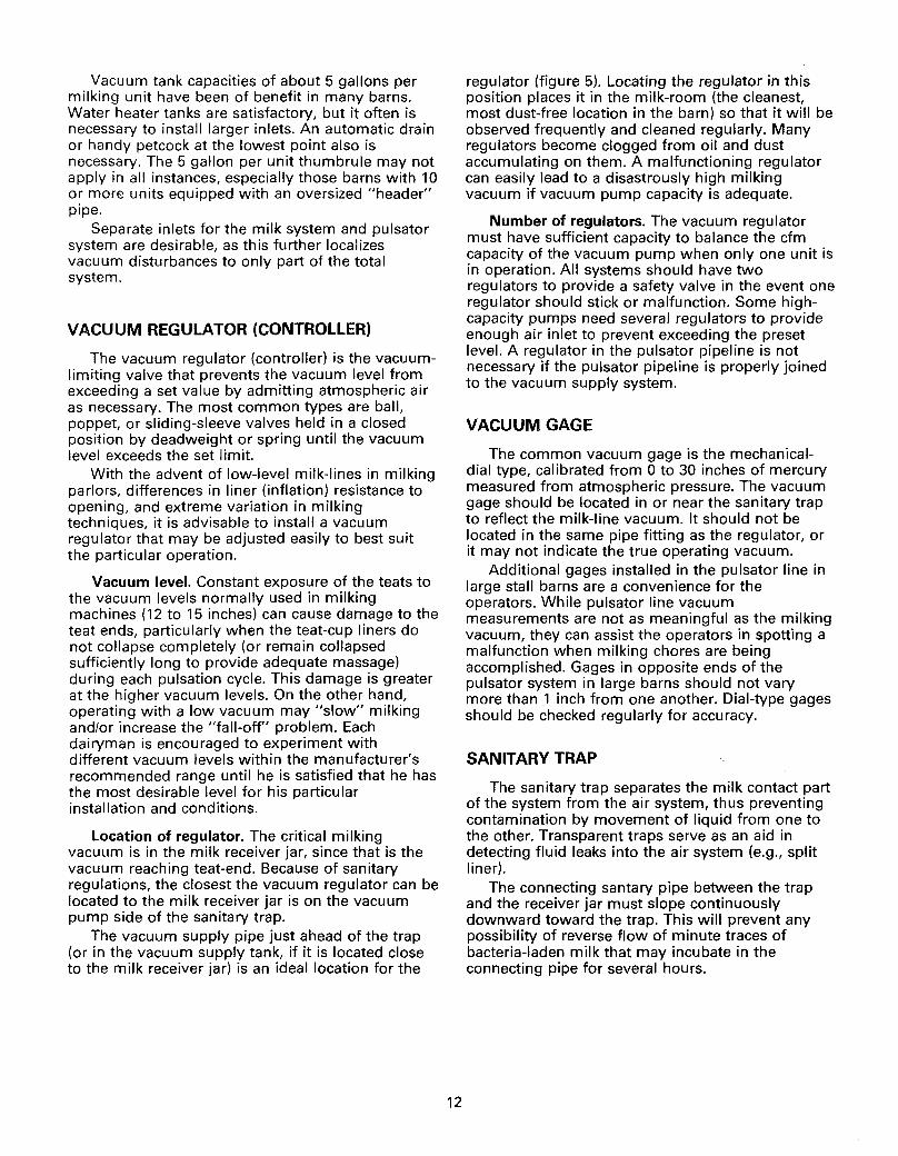
With new stall-barn construction, the milk-room should be at one end of the barn with the barn floor built to slope downward 1 to 1% inches per 10 feet toward the milk-room. Thus, the milk pipeline can be kept at a minimum, uniform height from the floor through the entire length of the barn (figure 7).
It is impractical to consider low-level milk lines in most barns because of slope problems. However, some dairymen contemplating new construction are
..... r-~~ I
r I~ ~I I
--- _'-1_
"' ...-: .... I ... ~@e ... I
.... ... ..... b .... ' ~ I (I) (I) .... 1!!? !!?,_...
I 0 0 I ..... ~ .... .... lllJ:' 'tJ 'tJ .... ~~ 0
'tJ .... I~
(1) .... 1(1) ~~~ IN
(I) 'v 0 ...
~I ... I
~I ... I
I I I .....
Milk
~ ... ~ Room
~~ L-- i:()R ... ..... 'tJ .... ~ (1)
N (I) .... .... 0
'tJ (1) ...
U2 ..... ..... ~IU• u, .... .... .....
I .... IU3 U2 ... (I) (I)
0 0 ... 'tJ 'tJ ... (1) (1) ... ... .... .....
I Milk
.... I ..... Room
I ___ --- :Q_R
..... U2
... u,
u, .... ~ Milk Room
L ____ ---fVR
A. B. c. 2-row face-out barn
Milk-room at end 1 %-inch line permits
4 units, provided
2-row face-out barn Milk-room near center 1 %-inch line permits
only 2 units
2-row face-in barn 1%-inch line permits
only 2 units
2 are on each slope
Notation: --=Slope 1 --------- = Slope 2
X = High point of milk line R = Receiver jar
• I = Cow facing right ~ = Cow facing left
M = Milking unit (!!) = Milking unit,
by second operator
Figure 7. Stall-barn layout and its influence on number of milking units used.
considering low-level milk-rooms (receiver jar on wall in the conventional manner) or installing the milk receiver and pump in a shallow pit at the end of the stanchion row. Be sure to obtain advance approval of state and local inspectors before installing a low-level system in a stanchion or tiestall barn.
Milking vacuum level in a low-line system usually is set 1 to 2 inches lower than in an equivalent overhead-pipeline system because of reduced vacuum differential between the pipeline and claw or teat-cup. Another advantage of the lowline system is that milk is less prone to become rancid because of the reduced agitation (mixing of milk and air).
While these features are desirable, a low-level system may require a surcingle, back cord, or arm to support the claw and hoses in the proper position.
Looped lines. In general, milk pipelines should have no dead ends. The milk pipe should be looped, and both ends should enter the milk receiver through separate inlets. The high point in the loop would be at the most remote point from the receiver.
14
In some milking parlors with large milk lines (2lh inches and up), there may be some deviation from the general recommendation that the milk pipeline be looped.
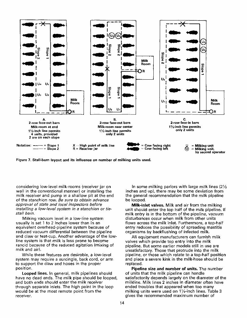
Milk-inlet valves. Milk and air from the milking unit should enter the top half of the milk pipeline. If milk entry is in the bottom of the pipeline, vacuum disturbances occur when milk from other units flows across the milk inlet. Furthermore, a top-half entry reduces the possibility of spreading mastitis organisms by backflushing of infected milk.
All equipment manufacturers can furnish milk valves which provide top entry into the milk pipeline. But some earlier models still in use are unsatisfactory. Those that protrude into the milk pipeline, or those which rotate to a top-half position and place a severe kink in the milk-hose should be replaced.
Pipeline size and number of units. The number of units that the milk pipeline can handle satisfactorily depends largely on the diameter of the milkline. Milk lines 2 inches in diameter often have ended troubles that appeared when too many milking units were used on 1 lh-inch lines. Table 3 gives the recommended maximum number of
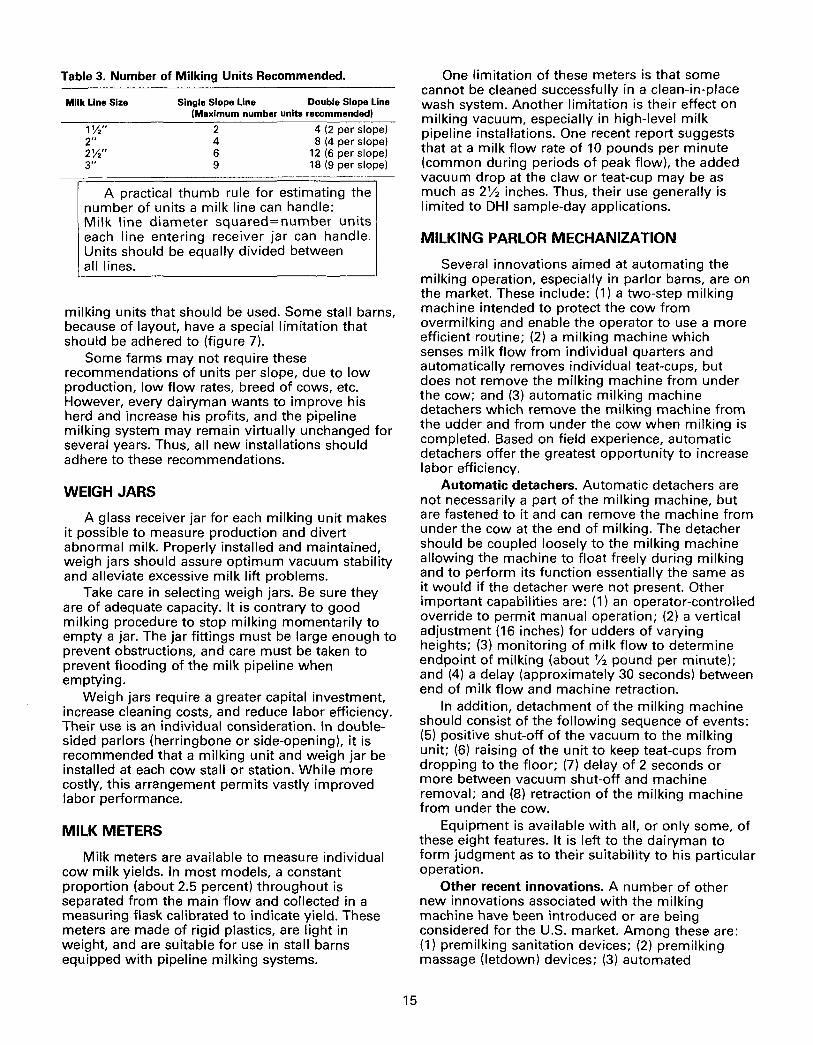
Table 3. Number of Milking Units Recommended.
Milk Line Size
1 1;2'' 2" 2'h" 3"
Single Slope Line Double Slope Line (Maximum number units recommended)
2 4 (2 per slope) 4 8 (4 per slope) 6 12 (6 per slope) 9 18 (9 per slope)
A practical thumb rule for estimating the number of units a milk line can handle: Milk line diameter squared=number units each line entering receiver jar can handle. Units should be equally divided between all lines.
milking units that should be used. Some stall barns, because of layout, have a special limitation that should be adhered to (figure 7).
Some farms may not require these recommendations of units per slope, due to low production, low flow rates, breed of cows, etc. However, every dairyman wants to improve his herd and increase his profits, and the pipeline milking system may remain virtually unchanged for several years. Thus, all new installations should adhere to these recommendations.
WEIGH JARS
A glass receiver jar for each milking unit makes it possible to measure production and divert abnormal milk. Properly installed and maintained, weigh jars should assure optimum vacuum stability and alleviate excessive milk lift problems.
Take care in selecting weigh jars. Be sure they are of adequate capacity. It is contrary to good milking procedure to stop milking momentarily to empty a jar. The jar fittings must be large enough to prevent obstructions, and care must be taken to prevent flooding of the milk pipeline when emptying.
Weigh jars require a greater capital investment, increase cleaning costs, and reduce labor efficiency. Their use is an individual consideration. In doublesided parlors (herringbone or side-opening), it is ~ecommended that a milking unit and weigh jar be rnstalled at each cow stall or station. While more costly, this arrangement permits vastly improved labor performance.
MILK METERS
Milk meters are available to measure individual cow milk yields. In most models, a constant proportion (about 2.5 percent) throughout is separated from the main flow and collected in a measuring flask calibrated to indicate yield. These meters are made of rigid plastics, are light in weight, and are suitable for use in stall barns equipped with pipeline milking systems.
15
One limitation of these meters is that some cannot be cleaned successfully in a clean-in-place wash system. Another limitation is their effect on milking vacuum, especially in high-level milk pipeline installations. One recent report suggests that at a milk flow rate of 10 pounds per minute (common during periods of peak flow), the added vacuum drop at the claw or teat-cup may be as much as 2Y:z inches. Thus, their use generally is limited to DHI sample-day applications.
MILKING PARLOR MECHANIZATION
Several innovations aimed at automating the milking operation, especially in parlor barns, are on the market. These include: (1) a two-step milking machine intended to protect the cow from overmilking and enable the operator to use a more efficient routine; (2) a milking machine which senses milk flow from individual quarters and automatically removes individual teat-cups, but does not remove the milking machine from under the cow; and (3) automatic milking machine detachers which remove the milking machine from the udder and from under the cow when milking is completed. Based on field experience, automatic detachers offer the greatest opportunity to increase labor efficiency.
Automatic detachers. Automatic detachers are not necessarily a part of the milking machine, but are fastened to it and can remove the machine from under the cow at the end of milking. The detacher should be coupled loosely to the milking machine allowing the machine to float freely during milking and to perform its function essentially the same as it would if the detacher were not present. Other important capabilities are: (1) an operator-controlled override to permit manual operation; (2) a vertical adjustment (16 inches) for udders of varying heights; (3) monitoring of milk flow to determine endpoint of milking (about Y:z pound per minute); and (4) a delay (approximately 30 seconds) between end of milk flow and machine retraction.
In addition, detachment of the milking machine should consist of the following sequence of events: (5) positive shut-off of the vacuum to the milking unit; (6) raising of the unit to keep teat-cups from dropping to the floor; (7) delay of 2 seconds or more between vacuum shut-off and machine removal; and (8) retraction of the milking machine from under the cow.
Equipment is available with all, or only some, of these eight features. It is left to the dairyman to form judgment as to their suitability to his particular operation.
Other recent innovations. A number of other new innovations associated with the milking machine have been introduced or are being considered for the U.S. market. Among these are: (1) premilking sanitation devices; (2) premilking massage (letdown) devices; (3) automated
postmilking teat-dip devices; (4) swinging vacuum, single chambered teat-cup milking units; and (5) nopulsation milking machines.
In general, these innovations will have only limited application in Minnesota because of the preponderance of stall barns and relatively small herds. Information regarding these developments is either very limited or nonexistent. Much of what is known is beyond the scope of this bulletin.
MILK FILTERS
Most filtering of milk on Minnesota dairy farms is through in-line pressure filters on the discharge side of the milk pump. These have the advantage of a completely closed system and no interference with the vacuum in the milk line. Disk-type filters placed in the milk-hose or in the bottom of each suspension cup are not recommended, even though they make possible the detection of mastitis in individual cows. Their detrimental influence on milking vacuum stability and the added labor required to change them when clogged are the basis for this conclusion.
MILK RECEIVER
The receiver may be either stainless steel or glass, the latter being desirable for its visibility but undesirable because of its breakage hazard. The receiver should have fittings for the vacuum line, each end of the looped milk line, and provisions for electrodes to start and stop the milk pump. The fittings should be at or near the top of the jar (above the highest potential milk level) to insure vacuum stability.
The receiver should be installed to maintain a uniform milk-pipe slope to its inlets with no risers in the system. Further, it should have sufficient clearance to allow simple installation of a milk pump underneath.
Receiver jar fittings should be sized to fit the milk pipelines leading to it, and should be
positioned to minimize "elbows" and other constrictions that tend to cause foaming of the milk. Excessive foam within the receiver may result in the pump being activated unnecessarily.
MILK PUMP
Most pumps operate under constant vacuum to remove-the milk from the receiver. The pump is switched on when the milk in the receiver rises to a predetermined level and is switched off before the receiver is emptied. This procedure keeps the pump primed and avoids excessive aeration of the milk.
Differential-vacuum milk releasers are less desirable than constant vacuum pumps in that they place an extra demand on the vacuum supply system, are not as foolproof, and are a common source of various pipeline problems.
BULK TANK
Most Minnesota dairymen use direct-expansion refrigerated bulk tanks to cool and store their milk. The size of farm tanks depends on herd size, frequency of pick-up, level of production, and herd growth potential. Since most milk pick-up schedules are every-other-day, the usual recommendation is to select a tank that will hold 3-days' production. This provides for periods of peak production and extra storage during inclement weather.
Vacuum bulk tanks that have airtight connections to the milk pipeline and are operated under milking vacuum have these advantages: (1) elimination of a milk receiver; (2) tremendous vacuum reserve capability; and (3) a closed system from cow-totruck. The disadvantages are: (1) added difficulty in filtering without disrupting the milking system; (2) less flexibility in equipment arrangement; (3) high initial cost; and (4) a tendency for seals, when old, to leak air, which requires more vacuum pump capacity.
ANALYTICAL CTESTINGJ EQUIPMENT
Reliable and adequate testing equipment is essential for milking system analysis. Such equipment removes guesswork and allows a competent operator to compare the operation of a system with established standards. A system failing to meet minimum capacity requirements is overloaded, and recommendations can be made to correct the condition.
16
VACUUM GAGE
An accurate portable vacuum gage is a simple piece of equipment useful when vacuum recorders are not available. Vacuum gages should be adjustable and of known accuracy. Equipment servicemen, dairy fieldmen, etc. regularly should compare their vacuum gages to a mercury column
and recalibrate the gages if necessary. Dairymen, then, should compare their gages against those which have been calibrated to a known standard.
Vacuum gages can be used to check vacuum levels at the teat end or as an aid to ascertaining proper operation of pulsators and vacuum regulators.
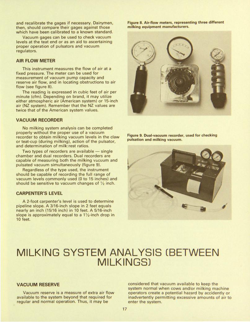
AIR FLOW METER
This instrument measures the flow of air at a fixed pressure. The meter can be used for measurement of vacuum pump capacity and reserve air flow, and in locating obstructions to air flow (see figure 8).
The reading is expressed in cubic feet of air per minute (cfm). Depending on brand, it may utilize either atmospheric air (American system) or 15-inch air (NZ system). Remember that the NZ values are twice that of the American system values.
VACUUM RECORDER
No milking system analysis can be completed properly without the proper use of a vacuum recorder to obtain milking vacuum levels in the claw or teat-cup (during milking), action of the pulsator, and determination of milk:rest ratios.
Two types of recorders are available- single chamber and dual recorders. Dual recorders are capable of measuring both the milking vc;cuum and pulsated vacuum simultaneously (figure 9).
Regardless of the type used, the instrument should be capable of recording the full range of vacuum levels commonly used (0 to 15 inches) and should be sensitive to vacuum changes of 1f2 inch.
CARPENTER'S LEVEL
A 2-foot carpenter's level is used to determine pipeline slope. A 3/16-inch slope in 2 feet equals nearly an inch (15/16 inch) in 10 feet. A 5/16-inch slope is approximately equal to a 11h-inch drop in 10 feet.
Figure 8. Air-flow meters, representing three different milking equipment manufacturers.
Figure 9. Dual-vacuum recorder, used for checking pulsation and milking vacuum.
MILKING SYSTEM ANALYSIS (BETWEEN MILKINGSJ
VACUUM RESERVE
Vacuum reserve is a measure of extra air flow available to the system beyond that required for regular and normal operation. Thus, it may be
17
considered that vacuum available to keep the system normal when cows and/or mi lking machine operators create a potential hazard by accidently or inadvertently permitting excessive amounts of air to enter the system.
Most qualified system analysts recommend that the total vacuum reserve should be from 3 to 5 cfm per milking unit, American system (6 to 10 cfm, NZ). New installations should approach the upper figure. Any recording below the lower value in an existing system is considered substandard, and corrective action is suggested. When vacuum reserve is in the 3 to 4 cfm range, the machine operator must use extreme care and caution in his handling of the milking units to insure adequate vacuum reserve.
Test procedure: (1) Set-up the total system to operate in the
normal manner. Hang all milking units in the milking parlor or barn so they will pulsate and draw air through the claw air-vent. Plug the teat-cups.
(2) Render all regulators (controllers) on the system inoperative by blocking the air passages or holding them closed.
(3) Remove the electrodes from the receiver jar fitting and place the air flow meter in this position. (Note: If there is insufficient clearance to permit this, use the opening for a removable wash plug or disconnect one leg of the milk pipeline at the receiver. Plug the receiver inlet and insert the air flow meter in the remaining opening.)
Interpretation: If vacuum reserve is less than 5 cfm per milking unit (American standard), check the following points.
(1) Is the rated capacity of the vacuum pump adequate?
(2) Does the pump perform according to standards? (Note: This can be checked by disconnecting the pipe extending from the vacuum pump at any point before it branches or enters the vacuum reserve tank and inserting the air flow meter.)
(3) Are the vacuum pump belts tight and free of oil and grease?
(4) Is the exhaust system piping at least the same diameter as the pump's exhaust port?
(5) Is the oiler functioning properly? (6) If none of the above checks provide an
adequate explanation for the lack of sufficient vacuum reserve, check for air leaks by isolating the pulsation and milking vacuum systems. (Note: Air leaks can be located by measuring cfm reserve at each end of an isolated system. Large differences in reserve air indicate that a leak exists.)
VACUUM SYSTEM RECOVERY CAPACITY
If the time required for the milking vacuum to regain its original operating level (after permitting a 5-second air leak through one teat-cup) exceeds 3 seconds, consider the milking system to be overloaded or malfunctioning.
18
Test Procedure: (1) Set-up the total system to operate in the
normal manner. Hang all milking units in the milking parlor or barn so they will pulsate and draw air through the claw air-vent. Plug the teat-cups.
(2) Use a portable vacuum gage in one teat-cup, and observe the vacuum level.
(3) Permit air to leak through another teat-cup in the same milking unit for 3 seconds. Then observe the time (in seconds) required to regain the original operating vacuum.
Interpretation: Dairymen not possessing an air flow meter may use a portable vacuum gage for checking whether a qualified serviceman or system analyst is needed. If the "recovery time" exceeds 5 seconds, it is recommended that a vacuum reserve check be made.
PULSATION CHECK- WITH VACUUM RECORDER
The pulsator ratio is the amount of time a pulsator admits vacuum (to open a liner) in relation to the time it admits air (to collapse the liner). Figure 10 shows how pulsator ratios are determined from a pulsated vacuum recording. Each curved line on the roll chart is considered to be 5 units of time. The proper reference points are the start of the vacuum creation phase, the start of the air admission phase, and the start of the next vacuum creation phase.
Test procedure: (1) Hook pulsation vacuum recorder to milking
unit by inserting "tee" between shell nipple and pulsation vacuum source. Plug teat-cup opening.
(2) Activate pulsator and obtain recording on roll chart. Note: If the milking system has an alternating pulsation feature, obtain two readings (one from each pulsation source). Repeat for each pulsator used.
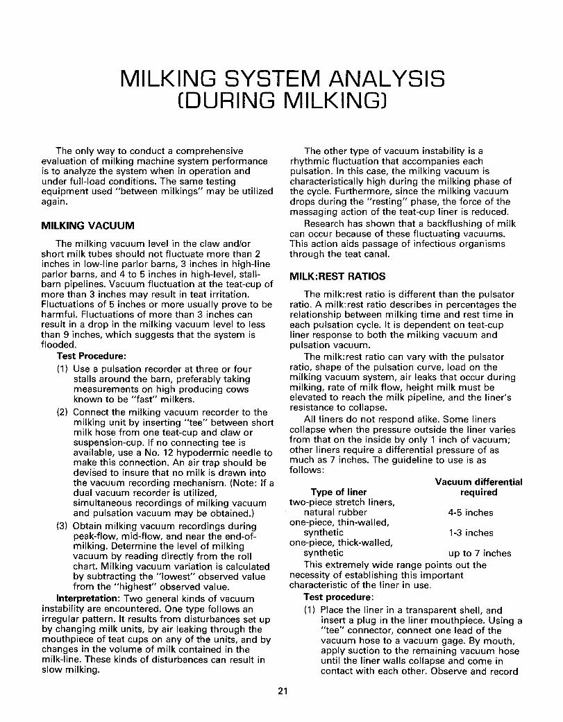
(3) Draw a vertical line at the beginning of each new pulsation phase (see figure 10). Measure the distance between each set of vertical lines. Determine the pulsator ratio by adding these two distances and referring to table 4.
Interpretation: The pulsated vacuum can be influenced by many kinds of pulsator deficiencies including wear, leaks, sticking parts, plugged ports, and faulty electrical timers and circuits.
Each make and model of pulsator: has its own characteristic configuration. The operator of the vacuum recorder soon learns to recognize a normal reading for pulsators in common use. With a normal recording in hand, or in mind, deviations are easily detected.
The broken lines in figure 11 illustrate two types of deviation from normal that are common. The
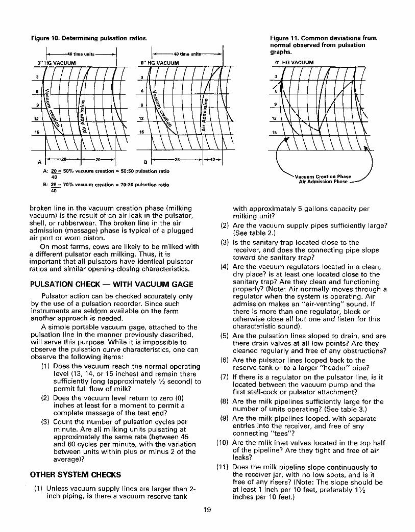
Figure 10. Determining pulsation ratios.
A -20
A: 20 = 50% vacuum creation = 50:50 pulsation ratio 40
B: 28 = 70% vacuum creation = 70:30 pulsation ratio 40
broken line in the vacuum creation phase (milking vacuum) is the result of an air leak in the pulsator, shell, or rubberwear. The broken line in the air admission (massage) phase is typical of a plugged air port or worn piston.
On most farms, cows are likely to be milked with a different pulsator each milking. Thus, it is important that all pulsators have identical pulsator ratios and similar opening-closing characteristics.
PULSATION CHECK- WITH VACUUM GAGE
Pulsator action can be checked accurately only by the use of a pulsation recorder. Since such instruments are seldom available on the farm another approach is needed.
A simple portable vacuum gage, attached to the pulsation line in the manner previously described, will serve this purpose. While it is impossible to observe the pulsation curve characteristics, one can observe the following items:
(1) Does the vacuum reach the normal operating level (13, 14, or 15 inches) and remain there sufficiently long (approximately Yz second) to permit full flow of milk?
(2) Does the vacuum level return to zero (0) inches at least for a moment to permit a complete massage of the teat end?
(3) Count the number of pulsation cycles per minute. Are all milking units pulsating at approximately the same rate (between 45 and 60 cycles per minute, with the variation between units within plus or minus 2 of the average)?
OTHER SYSTEM CHECKS
(1) Unless vacuum supply lines are larger than 2-inch piping, is there a vacuum reserve tank
19
Figure 11. Common deviations from normal observed from pulsation graphs.
0" HG VACUUM
with approximately 5 gallons capacity per milking unit?
(2) Are the vacuum supply pipes sufficiently large? (See table 2.)
(3) Is the sanitary trap located close to the receiver, and does the connecting pipe slope toward the sanitary trap?
(4) Are the vacuum regulators located in a clean, dry place? Is at least one located close to the sanitary trap? Are they clean and functioning properly? (Note: Air normally moves through a regulator when the system is operating. Air admission makes an "air-venting" sound. If there is more than one regulator, block or otherwise close all but one and listen for this characteristic sound).
(5) Are the pulsation lines sloped to drain, and are there drain valves at all low points? Are they cleaned regularly and free of any obstructions?
(6) Are the pulsator lines looped back to the reserve tank or to a larger "header" pipe?
(7) If there is a regulator on the pulsator line, is it located between the vacuum pump and the first stall-cock or pulsator attachment?
(8) Are the milk pipelines sufficiently large for the number of units operating? (See table 3.)
(9) Are the milk pipelines looped, with separate entries into the receiver, and free of any connecting "tees"?
(10) Are the milk inlet valves located in the top half of the pipeline? Are they tight and free of air leaks?
(11) Does the milk pipeline slope continuously to the receiver jar, with no low spots, and is it free of any risers? (Note: The slope should be at least 1 inch per 10 feet, preferably 1 Yz inches per 10 feet.)
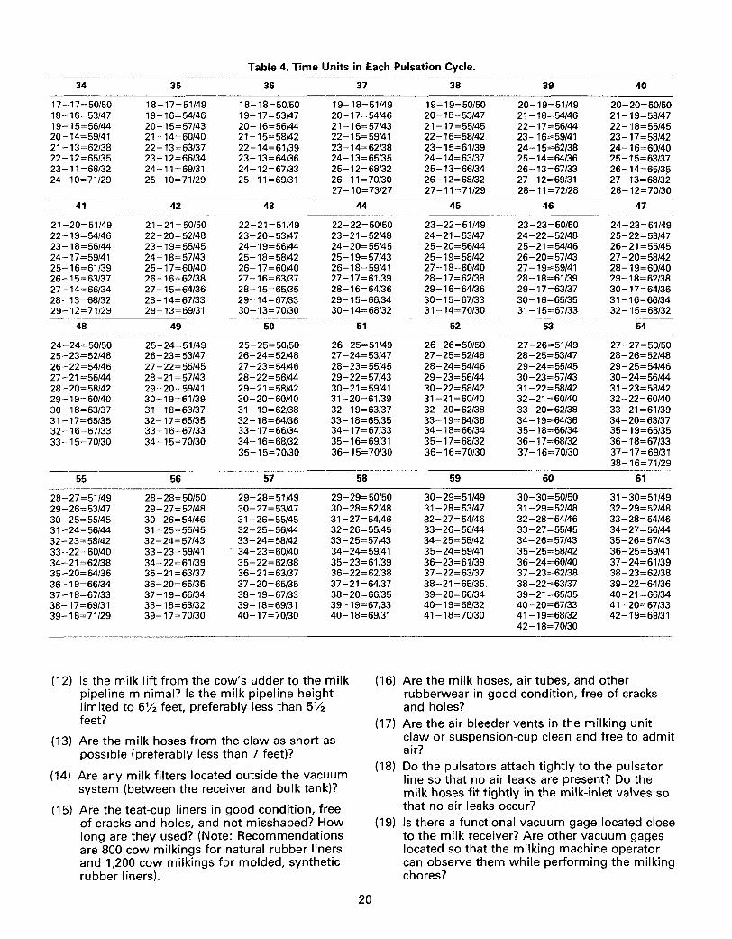
Table 4. Time Units in Each Pulsation Cycle.
34 35 36 37 38 39 40
17-17=50/50 18-17=51/49 18-18=50/50 19-18=51/49 19-19=50/50 20-19=51/49 20-20=50/50 18-16=53/47 19-16=54/46 19-17=53/47 20-17=54/46 20-18=53/47 21-18=54/46 21-19=53/47 19-15= 56/44 20-15=57/43 20-16= 56/44 21-16=57/43 21-17=55/45 22-17=56/44 22-18=55/45 20-14=59/41 21-14=60/40 21-15=58/42 22-15=59/41 22-16=58/42 23-16=59/41 23-17=58/42 21-13=62/38 22-13=63/37 22-14=61/39 23-14=62/38 23-15=61/39 24-15=62/38 24-16=60/40 22-12=65/35 23-12=66/34 23-13=64/36 24-13=65/35 24-14=63/37 25-14=64/36 25-15=63/37 23-11 =68/32 24-11 =69/31 24-12=67/33 25-12=68/32 25-13=66/34 26-13=67/33 26-14=65/35 24-10=71/29 25-10=71/29 25-11=69/31 26-11 = 70/30 26-12=68/32 27-12=69/31 27-13=68/32
27-1 0= 73/27 27-11=71/29 28-11 = 72/28 28-12=70/30
41 42 43 44 45 46 47
21-20=51/49 21-21 =50/50 22-21 =51/49 22-22=50/50 23-22=51/49 23-23=50/50 24-23=51/49 22-19=54/46 22-20=52/48 23-20=53/47 23-21 =52/48 24-21=53/47 24-22=52/48 25-22=53/47 23-18= 56/44 23-19=55/45 24-19= 56/44 24-20=55/45 25-20=56/44 25-21 =54/46 26-21=55/45 24-17=59/41 24-18=57/43 25-18=58/42 25-19=57/43 25-19=58/42 26-20=57/43 27-20=58/42 25-16=61/39 25-17=60/40 26-17=60/40 26-18=59/41 27-18=60/40 27 -19= 59/41 28-19=60/40 26-15= 63/37 26-16=62/38 27 -16= 63/37 27-17=61/39 28-17=62/38 28-18=61/39 29-18=62/38 27-14=66/34 27-15=64/36 28-15=65/35 28-16=64/36 29-16=64/36 29-17=63/37 30-17=64/36 28-13=68/32 28-14=67/33 29-14=67/33 29-15=66/34 30-15=67/33 30-16=65/35 31-16=66/34 29-12=71/29 29-13=69/31 30-13=70/30 30-14=68/32 31-14=70/30 31-15=67/33 32-15=68/32
48 49 50 51 52 53 54
24-24=50/50 25-24=51/49 25- 25= 50/50 26-25=51/49 26-26=50/50 27-26=51/49 27- 27 =50/50 25-23=52/48 26-23=53/47 26-24=52/48 27-24=53/47 27-25=52/48 28-25=53/47 28-26=52/48 26-22=54/46 27- 22 = 55/45 27-23=54/46 28-23=55/45 28-24=54/46 29-24=55/45 29-25=54/46 27-21 =56/44 28-21=57/43 28-22=56/44 29-22=57/43 29-23=56/44 30-23=57/43 30-24=56/44 28-20=58/42 29- 20= 59/41 29-21 =58/42 30-21=59/41 30-22=58/42 31-22=58/42 31-23=58/42 29-19= 60/40 30-19=61/39 30-20=60/40 31-20=61/39 31-21 =60/40 32-21 =60/40 32-22=60/40 30-18=63/37 31-18=63/37 31-19=62/38 32-19=63/37 32-20=62/38 33-20=62/38 33-21=61/39 31-17=65/35 32-17=65/35 32-18=64/36 33-18=65/35 33-19=64/36 34-19=64/36 34-20=63/37 32-16=67/33 33-16=67/33 33-17=66/34 34-17=67/33 34-18=66/34 35-18=66/34 35-19=65/35 33-15=70/30 34-15=70/30 34-16=68/32 35-16=69/31 35-17=68/32 36-17=68/32 36-18=67/33
35-15= 70/30 36-15= 70/30 36-16= 70/30 37-16=70/30 37-17=69/31 38-16=71/29
55 56 57 58 59 60 61
28-27=51/49 28-28=50/50 29-28=51/49 29-29=50/50 30-29=51/49 30-30=50/50 31-30=51/49 29-26=53/47 29-27=52/48 30-27=53/47 30-28=52/48 31-28=53/47 31 - 29= 52/48 32-29=52/48 30-25=55/45 30-26=54/46 31 - 26= 55/45 31-27=54/46 32-27=54/46 32-28=54/46 33-28=54/46 31-24=56/44 31-25=55/45 32-25=56/44 32-26=55/45 33-26=56/44 33-27=55/45 34-27=56/44 32-23=58/42 32-24=57/43 33-24=58/42 33-25=57/43 34-25=58/42 34-26=57/43 35-26=57/43 33-22=60/40 33-23=59/41 . 34-23=60/40 34-24=59/41 35-24=59/41 35-25=58/42 36-25=59/41 34- 21 = 62/38 34-22=61/39 35-22=62/38 35-23=61/39 36-23=61/39 36-24=60/40 37-24=61/39 35-20=64/36 35-21 =63/37 36-21=63/37 36-22=62/38 37-22=63/37 37-23=62/38 38-23=62/38 36-19= 66/34 36-20=65/35 37-20=65/35 37-21 =64/37 38-21 =65/35. 38-22=63/37 39-22=64/36 37-18=67/33 37-19=66/34 38-19= 67/33 38-20=66/35 39-20=66/34 39-21 =65/35 40-21=66/34 38-17=69/31 38-18=68/32 39-18=69/31 39-19=67/33 40-19=68/32 40-20=67/33 41-20=67/33 39-16=71/29 39-17=70/30 40-17=70/30 40-18=69/31 41-18=70/30 41-19=68/32 42-19=69/31
42-18=70/30
(12) Is the milk lift from the cow's udder to the milk pipeline minimal? Is the milk pipeline height limited to 6% feet, preferably less than 5% feet?
(16) Are the milk hoses, air tubes, and other rubberwear in good condition, free of cracks and holes?
(17) Are the air bleeder vents in the milking unit claw or suspension-cup clean and free to admit air?
(13) Are the milk hoses from the claw as short as possible (preferably less than 7 feet)?
(14) Are any milk filters located outside the vacuum system (between the receiver and bulk tank)?
(15) Are the teat-cup liners in good condition, free of cracks and holes, and not misshaped? How long are they used? (Note: Recommendations are 800 cow milkings for natural rubber liners and 1,200 cow milkings for molded, synthetic rubber liners).
20
(18) Do the pulsators attach tightly to the pulsator line so that no air leaks are present? Do the milk hoses fit tightly in the milk-inlet valves so that no air leaks occur?
(19) Is there a functional vacuum gage located close to the milk receiver? Are other vacuum gages located so that the milking machine operator can observe them while performing the milking chores?
MILKING SYSTEM ANALYSIS (DURING MILKING)
The only way to conduct a comprehensive evaluation of milking machine system performance is to analyze the system when in operation and under full-load conditions. The same testing equipment used "between milkings" may be utilized again.
MILKING VACUUM
The milking vacuum level in the claw and/or short milk tubes should not fluctuate more than 2 inches in low-line parlor barns, 3 inches in high-line parlor barns, and 4 to 5 inches in high-level, stallbarn pipelines. Vacuum fluctuation at the teat-cup of more than 3 inches may result in teat irritation. Fluctuations of 5 inches or more usually prove to be harmful. Fluctuations of more than 3 inches can result in a drop in the milking vacuum level to less than 9 inches, which suggests that the system is flooded.
Test Procedure: (1) Use a pulsation recorder at three or four
stalls around the barn, preferably taking measurements on high producing cows known to be "fast" milkers.
(2) Connect the milking vacuum recorder to the milking unit by inserting "tee" between short milk hose from one teat-cup and claw or suspension-cup. If no connecting tee is available, use a No. 12 hypodermic needle to make this connection. An air trap should be devised to insure that no milk is drawn into the vacuum recording mechanism. (Note: If a dual vacuum recorder is utilized, simultaneous recordings of milking vacuum and pulsation vacuum may be obtained.)
(3) Obtain milking vacuum recordings during peak-flow, mid-flow, and near the end-ofmilking. Determine the level of milking vacuum by reading directly from the roll chart. Milking vacuum variation is calculated by subtracting the "lowest" observed value from the "highest" observed value.
Interpretation: Two general kinds of vacuum instability are encountered. One type follows an irregular pattern. It results from disturbances set up by changing milk units, by air leaking through the mouthpiece of teat cups on any of the units, and by changes in the volume of milk contained in the milk-line. These kinds of disturbances can result in slow milking.
21
The other type of vacuum instability is a rhythmic fluctuation that accompanies each pulsation. In this case, the milking vacuum is characteristically high during the milking phase of the cycle. Furthermore, since the milking vacuum drops during the "resting" phase, the force of the massaging action of the teat-cup liner is reduced.
Research has shown that a backflushing of milk can occur because of these fluctuating vacuums. This action aids passage of infectious organisms through the teat canal.
MILK:REST RATIOS
The milk:rest ratio is different than the pulsator ratio. A milk:rest ratio describes in percentages the relationship between milking time and rest time in each pulsation cycle. It is dependent on teat-cup liner response to both the milking vacuum and pulsation vacuum.
The milk:rest ratio can vary with the pulsator ratio, shape of the pulsation curve, load on the milking vacuum system, air leaks that occur during milking, rate of milk flow, height milk must be elevated to reach the milk pipeline, and the liner's resistance to collapse.
All liners do not respond alike. Some liners collapse when the pressure outside the liner varies from that on the inside by only 1 inch of vacuum; other liners require a differential pressure of as much as 7 inches. The guideline to use is as follows:
Type of liner two-piece stretch liners,
natural rubber one-piece, thin-walled,
synthetic one-piece, thick-walled,
Vacuum differential required
4-5 inches
1-3 inches
synthetic up to 7 inches This extremely wide range points out the
necessity of establishing this important characteristic of the liner in use.
Test procedure: (1) Place the liner in a transparent shell, and
insert a plug in the liner mouthpiece. Using a "tee" connector, connect one lead of the vacuum hose to a vacuum gage. By mouth, apply suction to the remaining vacuum hose until the liner walls collapse and come in contact with each other. Observe and record
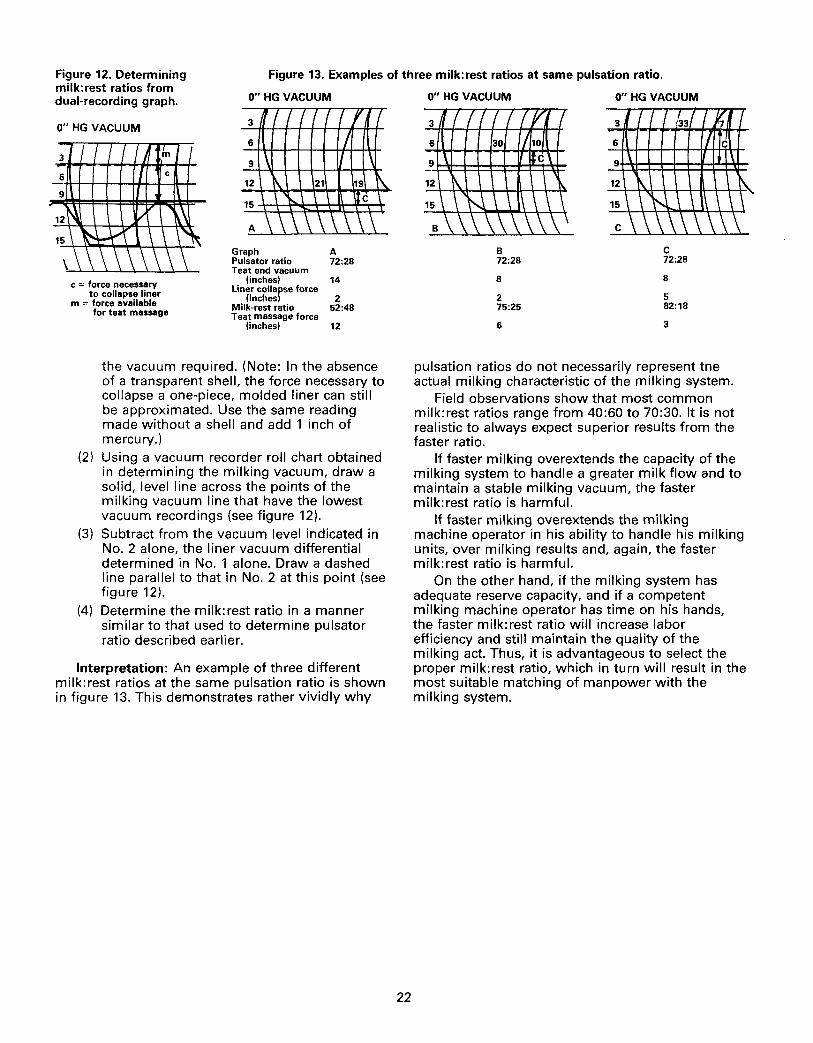
Figure 12. Determining milk:rest ratios from dual-recording graph.
Figure 13. Examples of three milk: rest ratios at same pulsation ratio.
0" HG VACUUM
3 1/1 11 /f I 0" HG VACUUM
6
9 1 \ 12 t\ 21 19 t\. 15 \\. I \ \ \t_c l
c = force necessary to collapse liner
m = force available for teat massage
A \\ \ \ Graph A Pulsator ratio 72:28 Teat end vacuum
(inches) 14 Liner collapse force
(inches) 2 Milk-rest ratio 52:48 Teat massage force
(inches) 12
the vacuum required. (Note: In the absence of a transparent shell, the force necessary to collapse a one-piece, molded liner can still be approximated. Use the same reading made without a shell and add 1 inch of mercury.)
(2) Using a vacuum recorder roll chart obtained in determining the milking vacuum, draw a solid, level line across the points of the milking vacuum line that have the lowest vacuum recordings (see figure 12).
(3) Subtract from the vacuum level indicated in No. 2 alone, the liner vacuum differential determined in No. 1 alone. Draw a dashed line parallel to that in No. 2 at this point (see figure 12).
(4) Determine the milk:rest ratio in a manner similar to that used to determine pulsator ratio described earlier.
Interpretation: An example of three different milk: rest ratios at the same pulsation ratio is shown in figure 13. This demonstrates rather vividly why
22
0" HG VACUUM
B 72:28
8
2 75:25
6
0" HG VACUUM
c 72:28
8
5 82:18
3
pulsation ratios do not necessarily represent tne actual milking characteristic of the milking system.
Field observations show that most common milk:rest ratios range from 40:60 to 70:30. It is not realistic to always expect superior results from the faster ratio.
If faster milking overextends the capacity of the milking system to handle a greater milk flow and to maintain a stable milking vacuum, the faster milk:rest ratio is harmful.
If faster milking overextends the milking machine operator in his ability to handle his milking units, over milking results and, again, the faster milk:rest ratio is harmful.
On the other hand, if the milking system has adequate reserve capacity, and if a competent milking machine operator has time on his hands, the faster milk:rest ratio will increase labor efficiency and still maintain the quality of the milking act. Thus, it is advantageous to select the proper milk:rest ratio, which in turn will result in the most suitable matching of manpower with the milking system.
SUMMARY Recommendations that milking equipment servicemen and/or analysts make must be based on common
sense, an understanding of dairy herd management, and a practical knowledge of the milking system. All substandard systems should be brought up to standard. The best test of a system analysis is a recheck after recommendations have been followed.
If the system is found to be operating "normally," then the dairyman must look elsewhere for reasons why he has a high "bulk milk" somatic cell count or too much "clinical" mastitis. Infected cows, too many late-lactation cows, too many milking units per machine operator, improper milking procedures, or neutralto-ground voltage problems on the dairy farm are possible causes.
If the system is found to be overloaded, there are only two reasonable solutions: (1) reduce the number of milking units used, to better fit the capacity of the system, or (2) bring the system up to the capacity needed to do the job. Excess pump capacity is not harmful as long as the vacuum level is controlled properly.
RELATED REFERENCE MATERIALS
UNIVERSITY OF MINNESOTA PUBLICATIONS
1. CMT, Your Tool For Detecting Subclinical Mastitis, Ext. Folder 322.
2. "Neutral-to-Ground Voltage Problems with Dairy Cows," Dairy Husb. Fact Sheet No. 21.
23
OTHER REFERENCES AVAILABLE
1. The Modern Way To Efficient Milking. The Milking Machine Manufacturer's Council, Farm and Industrial Equipment Institute, 410 N. Michigan Ave., Chicago, IL 60521. 36 pages.
2. Proceedings, 1978 International Symposium on Machine Milking. National Mastitis Council, Inc., 30F Street, N.W., Washington, D.C. 20001. 477 pages.
3. Machine Milking. The Librarian, National Institute for Research in Dairying, Reading RG2 9AT, England. 391 pages.