Embed Size (px)
Citation preview

High Temperature Heat Pump
– Theoretical study on
low GWP HFO and HCFO
refrigerants
C. Arpagaus, M. Prinzing, R. Kuster,
F. Bless, M. Uhlmann, S.S. Bertsch,
NTB Buchs
J. Schiffmann, EPFL Neuchâtel
ICR 2019, The 25th IIR International Congress of
Refrigeration, Montréal, Québec, Canada
August 24-30, 2019INSTITUTE FOR
ENERGY SYSTEMS
ICR 2019, August 30, 2019 [email protected] 2
Content
Introduction
High Temperature Heat Pumps (HTHPs): waste heat recovery in industry, products, research gaps
Hydrofluoroolefins (HFOs) and hydrochlorofluoroolefins (HCFOs) as 4th generation of low GWP refrigerants for HTHPs
Theoretical studies on different HTHP cycles with HFOs and HCFOs
Simulation model
Selected and investigated heat pump cycles
Assumptions, parameters and variation range
Simulation results and discussion
Comparison of performance parameters (COP, VHC, pRatio, TDischarge)
Operating maps, optimal COP
Conclusions

Principle of waste heat recovery by industrial heat pumps
Introduction – waste heat recovery in industry
ICR 2019, August 30, 2019 [email protected] 3
Motivation:
Replace fuel-driven
boilers for generation
of hot water, hot air
and steam
Reduce CO2
emissions
Energy savings

R245fa is predominantly used in today’s industrial HTHP
Introduction – market overview of HTHPs for industrial applications
ICR 2019, August 30, 2019 [email protected] 4
160°C
Ma
x.
heat supply
te
mpera
ture
[°C
]
Heating capacity [kW]
Screw Piston Turbo
HeatBooster S4
(Viking Heating
Engines AS)
Kobelco SGH 120/165
(Steam Grow HP)R134a/R245faR1336mzz(Z)R245fa
R245faR717 (NH3)
R245faR245faR245fa
R1233zd(E)R1234ze(E)R1234ze(E)R134a/R1234ze(E)R744 (CO2)
R134aR717 (NH3)R717 (NH3)R717 (NH3)R717 (NH3)R134aR717 (NH3)R1234ze(E)
R744 (CO2)R134a/R245fa
R245faR744 (CO2)
Refrigerants
Arpagaus et al. (2018)

What are the research gaps in HTHPs?
Introduction – motivation of future research
ICR 2019, August 30, 2019 [email protected] 5
Development and testing of new environmentally
friendly synthetic refrigerants
(e.g. HFOs and HCFOs with very low GWP)
Application of natural refrigerants, such as
hydrocarbons (R600, R601), CO2 or water
Extending the limits of heat source (TSource) and
heat supply temperatures (TSink) to higher values
Improving heat pump efficiency (COP )
(e.g. by multi-stage cycles, oil-free compressors)
Development of temperature-resistant components
(e.g. valves, compressors)
Optimization and development of heat pump systems
with new control strategies for higher temperatures
Scale-up of functional models to industrial scale
(demonstration projects)

The 4th generation of synthetic low GWP refrigerants
for chiller, ORC, and HTHP applications
Introduction – refrigerants
ICR 2019, August 30, 2019 [email protected] 6
CFC
(R113)
HCFC
(R123)
HFC
(R245fa)
Montréal Protocol
(1987)
Regulation
(2037/2000)
Kyoto Protocol
(1997)
EU F-Gas Regulation
(517/2014)
Paris Agreement
(2015)
Ozone layer
depletion
Global warming
geeenhouse gases
Cost
increase
CFC: fully halogenated chlorofluorocarbons
HCFC: partially halogenated chlorofluorocarbons
HFC: hydrofluorocarbons
HFO: hydrofluoroolefins
HCFO: hydrochlorofluoroolefins
R1336mzz(Z)
R1224yd(Z)
R1233zd(E)
HFO
(R1336mzz(Z))
HCFO
(R1233zd(E),
R1224yd(Z))
Criteria :
low GWP
short atm. lifetime
zero/low ODP
low flammability
high efficiency
high Tcrit

Properties of selected HFO and HCFO refrigerants for HTHP applications
Introduction – refrigerant properties
ICR 2019, August 30, 2019 [email protected] 7
Refrigerant StructureTcrit
(°C)
pcrit
(bar)
pRatio*
(-)
ODP
(-)
GWP100
(-)
Lifetime
(days)SG
NBP
(°C)
M
(g/mol)
R1336mzz(Z) Z-CF3-CH=CHCF3 171.3 29 4.3 0 2 22 A1 33.4 164.1
R1233zd(E) E-CF3-CH=CHCl 165.6 35.7 3.9 0.00034 1 26 A1 18 130.5
R1224yd(Z)a Z-CF3-CF=CHCl 155.5 33.4 3.8 0.00023 0.88 20 A1 14 148.5
R1234ze(Z) Z-CF3-CH=CHF 150.1 35.3 3.7 0 <1 10 A2L 9.8 114
R1336mzz(E)** E-CF3-CH=CHCF3 171.3 31.5 3.8 0 18 90 n.a. 7.5 164.1
R1234ze(E)+ E-CF3-CH=CHF 109.4 36.3 3.2 0 <1 16.4 A2L -19 114
R1234yf+ CF3-CF=CH2 94.7 33.8 3 0 <1 11 A2L -29.5 114
R134a+ CF3-CH2F 101 40.6 3.2 0 1300 13.4 years A1 -26.3 102
R365mfc+ CF3-CH2-CF2-CH3 186.9 32.7 4.6 0 804 8.7 years A2 40.2 148.1
R245fa+ CHF2-CH2-CF3 154 36.5 4 0 858 7.7 years B1 14.9 134
GWP100, atmospheric lifetimes: Myhre et al. (2013), IPCC 5th assessment report, a Tokuhashi et al. (2018), + for a low stage (LS) cycle, ++ for comparison, * 40 to 90 °C temperature lift,
** fluid properties not yet available in the EES software (Engineering Equation Solver) V10.643 from F-Chart

T-s, p-T diagrams of selected HFO and HCFO refrigerants
Introduction – refrigerant properties
ICR 2019, August 30, 2019 [email protected] 8

Simulated COP of selected HFO and HCFO refrigerants in a basic HP cycle
Introduction – refrigerant properties
ICR 2019, August 30, 2019 [email protected] 9
is = 0.7
Simulated COP rise to an optimum
and decrease with the narrowing of
the 2-phase region up to Tcrit
Optimal COP at about 30 K below
the critical temperature
R365mfc offers highest COP,
followed by R1233zd(E) and
R1336mzz(Z)
R1234ze(Z) and R1224yd(Z)
comparable to R245fa
R1234yf and R1234ze(E) similar to
R134a
Arpagaus et al. (2018)

Theoretical studies with HFO and HCFO refrigerants in different HTHP cycles
Introduction – theoretical studies from literature
ICR 2019, August 30, 2019 [email protected] 10

Goal of this study
Introduction – objective
ICR 2019, August 30, 2019 [email protected] 11
This study examines the suitability of R1336mzz(Z), R1233zd(E), R1224yd(Z),
R1234ze(Z), R1234ze(E) and R1234yf for HTHP application and presents simulations in
the following heat pump cycles:
1-stage cycle with IHX
2-stage cycle with economizer and IHX
2-stage cycle with flash tank and IHX
2-stage cascade with two IHX
by evaluation of:
thermodynamic efficiency (COP),
volumetric heating capacity (VHC)
pressure ratio (pRatio),
discharge temperature (TDischarge), and
comparison with today’s HFC refrigerants R365mfc, R245fa, and R245fa/R134a.

Investigated heat pump cycles with log(p)-h diagrams
Simulation model
ICR 2019, August 30, 2019 [email protected] 12
1-stage cycle with IHX 2-stage cascade with two IHX
2-stage cycle with
flash tank and IHX
2-stage cycle with
economizer and IHX

Parameters, reference conditions, and approach temperatures in the heat
exchangers (Cond, Eco, CAS, IHX, Evap)
Simulation model – parameters
ICR 2019, August 30, 2019 [email protected] 13
(*12 K superheat
for R1336mzz(Z)
and R365mfc to
assure dry
compression)

Basic assumptions
Simulation model
ICR 2019, August 30, 2019 [email protected] 14
Simplified thermodynamic cycle models developed in EES (Engineering
Equation Solver), F-Chart Software, V10.643 (Klein, 2019)
No parasitic heat losses and pressure drops
Isenthalpic expansion
Constant compressor isentropic efficiency of is = 0.7
Intermediate pressure in the 2-stage economizer and flash tank cycle
calculated as the geometric mean (square root) of the evaporation and
condensation pressures
Approach temperatures in heat exchangers considered constant for all
operating conditions
Steady state conditions
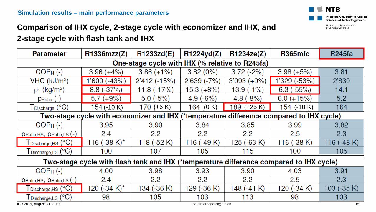
Comparison of IHX cycle, 2-stage cycle with economizer and IHX, and
2-stage cycle with flash tank and IHX
Simulation results – main performance parameters
ICR 2019, August 30, 2019 [email protected] 15
(-10 K) (+6 K) (0 K) (+25 K) (-10 K)
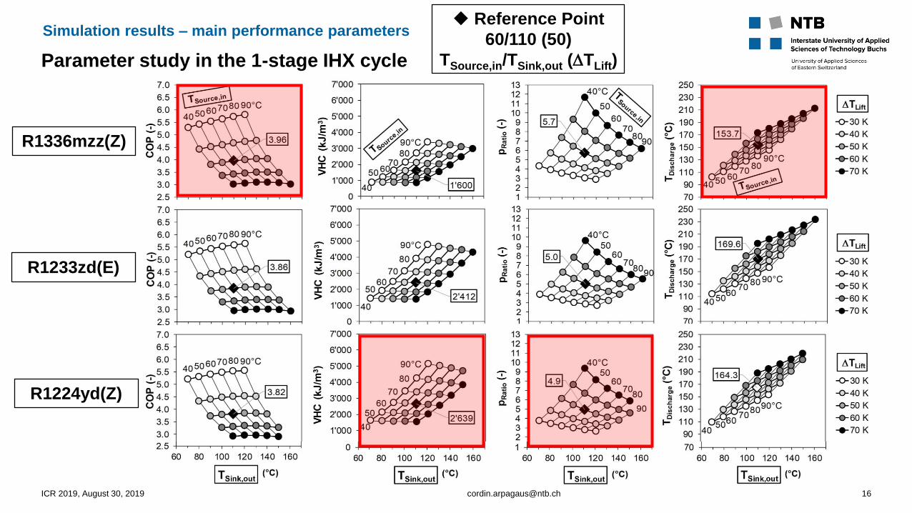
Parameter study in the 1-stage IHX cycle
Simulation results – main performance parameters
ICR 2019, August 30, 2019 [email protected] 16
Reference Point
60/110 (50)
TSource,in/TSink,out (TLift)
R1336mzz(Z)
R1233zd(E)
R1224yd(Z)

Maximum COP in the 2-stage cascade cycle wit IHX for different refrigerant pairs
Simulation results – two-stage cascade cycle with IHX
ICR 2019, August 30, 2019 [email protected] 17
60/110 (50)
TSource,in/TSink,out (TLift)
Min/Max optimization method (Golden Section) of EES
to find a COP maximum depending on TCond,CAS
LS
HS
LS: low stage
HS: high stage

Max. COP in the 2-stage CAS cycle with IHX for 24 pairs of HFO/HCFO refrigerants
Simulation results – two-stage cascade cycle with IHX
ICR 2019, August 30, 2019 [email protected] 18
(at 50 K TLift)
Highest COP with R1336mzz(Z) in both stages (COP of 3.91 at 60°C/110°C (Ref) conditions,
6% higher compared to R245fa/R134a)
TDischarge,HS between 130 and 172 °C (lower than in 1-stage cycle with IHX, but higher than in
2-stage economizer and flash tank cycle
°C

COP comparison of the investigated cycles using R1336mzz(Z)
at different temperature lifts (30, 50, and 70 K)
Simulation results – comparison of cycles
ICR 2019, August 30, 2019 [email protected] 19
The 2-stage flash tank (…) and economizer (---) cycles are more efficient for small and medium Tlift
With higher TLift, the 2-stage cascade cycle (___) compensates for the losses of the CAS heat
exchanger and achieves highest efficiency at 70 K lift
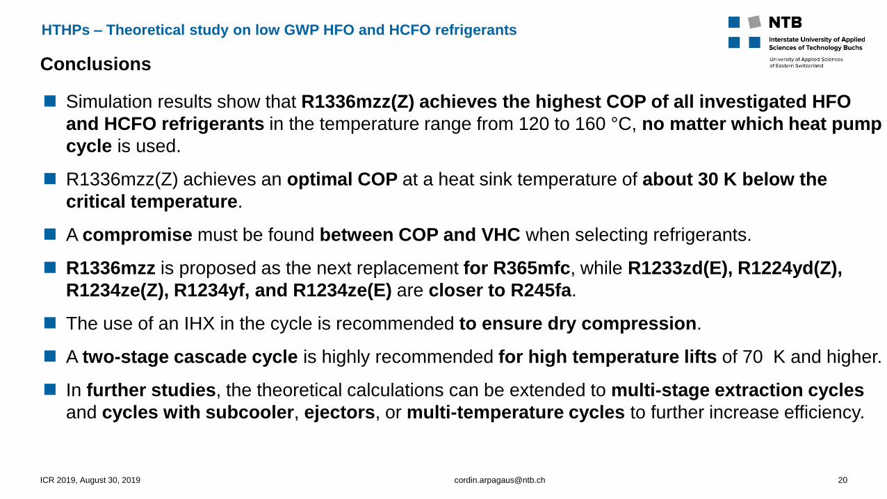
Conclusions
HTHPs – Theoretical study on low GWP HFO and HCFO refrigerants
Simulation results show that R1336mzz(Z) achieves the highest COP of all investigated HFO
and HCFO refrigerants in the temperature range from 120 to 160 °C, no matter which heat pump
cycle is used.
R1336mzz(Z) achieves an optimal COP at a heat sink temperature of about 30 K below the
critical temperature.
A compromise must be found between COP and VHC when selecting refrigerants.
R1336mzz is proposed as the next replacement for R365mfc, while R1233zd(E), R1224yd(Z),
R1234ze(Z), R1234yf, and R1234ze(E) are closer to R245fa.
The use of an IHX in the cycle is recommended to ensure dry compression.
A two-stage cascade cycle is highly recommended for high temperature lifts of 70 K and higher.
In further studies, the theoretical calculations can be extended to multi-stage extraction cycles
and cycles with subcooler, ejectors, or multi-temperature cycles to further increase efficiency.
ICR 2019, August 30, 2019 [email protected] 20

Acknowledgements
Thanks
ICR 2019, August 30, 2019 [email protected] 21
This research project is part of the
Swiss Competence Center for Energy Research SCCER EIP
of the Swiss Innovation Agency Innosuisse.
We would like to thank Innosuisse for their support.