Embed Size (px)
Citation preview

1398SBW024EN00 - 25-01-2018
ByWire Elements BW0511BO
BW0511BO - Element 4/3 ON - OFF with Top ports with Load sensing signal Interface IBW0511
Before use, carefully read the GENERAL INSTRUCTIONS FOR USE OF DIRECTIONAL CONTROL VALVES ByWire ElementsBW0511BO 398SBW024EN00 -
2 398SBW024EN00 - 25-01-2018
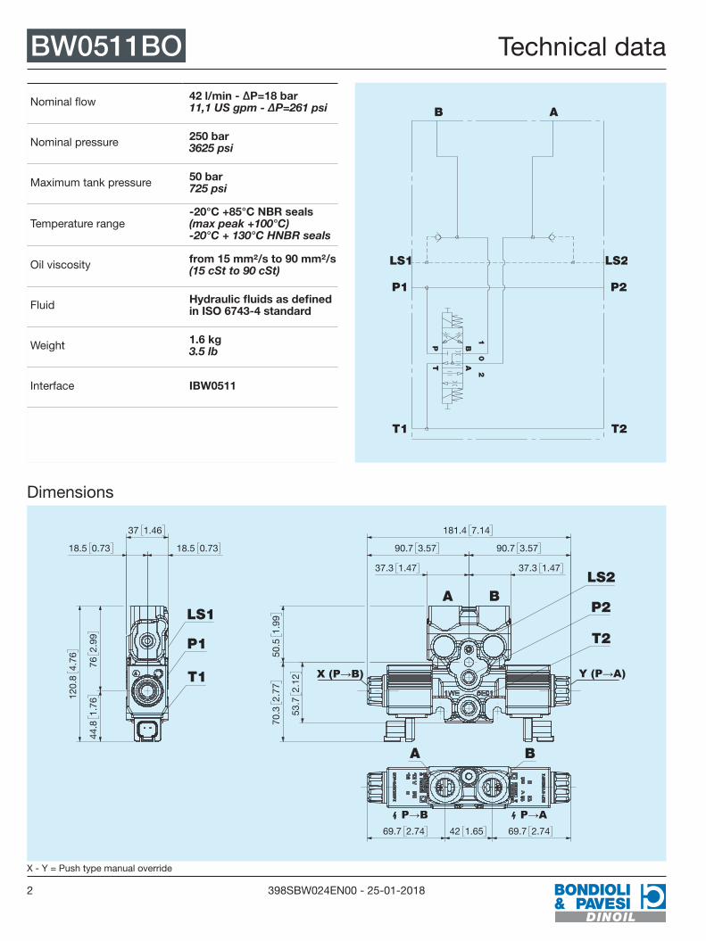
BW0511BO Technical data
Nominal flow 42 l/min - ∆P=18 bar 11,1 US gpm - ∆P=261 psi
Nominal pressure 250 bar 3625 psi
Maximum tank pressure 50 bar 725 psi
Temperature range-20°C +85°C NBR seals (max peak +100°C) -20°C + 130°C HNBR seals
Oil viscosity from 15 mm²/s to 90 mm²/s (15 cSt to 90 cSt)
Fluid Hydraulic fluids as defined in ISO 6743-4 standard
Weight 1.6 kg 3.5 lb
Interface IBW0511
P1
LS1
T2
P2
LS2
T1
AB
1
P
2
A
0
B
T
Dimensions
P→B P→A
37.3 1.47
90.7 3.57
181.4 7.14
37.3 1.47
90.7 3.57
50.5
1.99
70.3
2.77
53.7
2.12
Y (P→A)X (P→B)
A BLS2
P2
T2
69.7 2.74 42 1.65 69.7 2.74
A B
18.5 0.7318.5 0.73
37 1.46
762.
9944
.81.
76
120.
84.
76
LS1
T1
P1
X - Y = Push type manual override
Technical data

3398SBW024EN00 - 25-01-2018
Flow curve BW0511BOA/B-T flow curve
0 10 20 30 40 50 60 70 80[l/min]
0
10
20
30
40
50[bar]
TOIL = 50°C
vOIL = 21 mm2/s
Flow curve
4 398SBW024EN00 - 25-01-2018
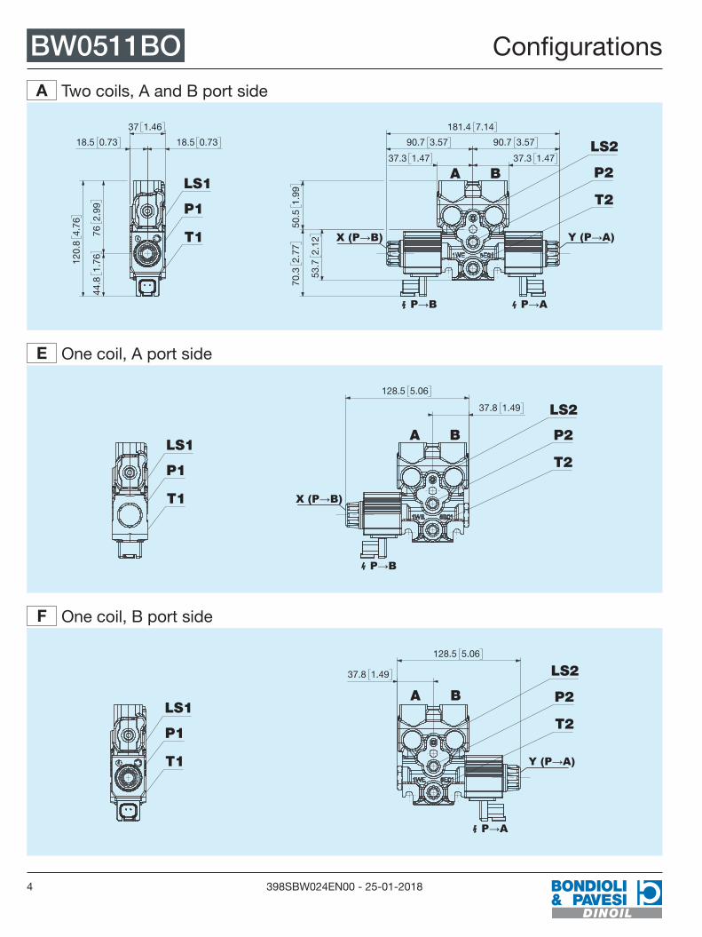
BW0511BO Configurations
A Two coils, A and B port side
P→B P→A
37.3 1.47
90.7 3.57
181.4 7.14
37.3 1.47
90.7 3.57
50.5
1.99
70.3
2.77
53.7
2.12
Y (P→A)X (P→B)
A B
LS2
P2
T2
18.5 0.7318.5 0.73
37 1.46
762.
9944
.81.
76120.
84.
76
LS1
T1
P1
E One coil, A port side
P→B
37.8 1.49
128.5 5.06
X (P→B)
A B
LS2
P2
T2LS1
T1
P1
F One coil, B port side
P→A
37.8 1.49
128.5 5.06
Y (P→A)
A B
LS2
P2
T2LS1
T1
P1
Configurations

5398SBW024EN00 - 25-01-2018
Configurations BW0511BOB Two coils, A and B port side and emergency lever
P→B P→A
138.4 5.45
229.1 9.02
90.8 3.58 47.5 1.87
17°
17°
742.
91
Y (P→A)X (P→B)
A B
LS2
(P→A)
(P→B)P2
T2
44.8
1.76
25.7 1.01
17 0.67
99.5
3.92
144.
35.
68
27.2 1.07
LS1
T1
P1
C One coil, A port side and emergency lever
P→B 85.3 3.36
17°
17°
742.
91
181.5 7.15
90.8 3.58
X (P→B)
A B
LS2
(P→B)P2
T2(P→A)
44.8
1.76
25.7 1.01
17 0.67
99.5
3.92
144.
35.
68
27.2 1.07
LS1
T1
P1
D One coil, B port side and emergency lever
P→A
176.2 6.94
90.8 3.58 47.5 1.87
17°
17°
742.
91
Y (P→A)
A B
LS2
(P→A)
(P→B)
P2
T2
44.8
1.76
25.7 1.01
17 0.67
99.5
3.92
144.
35.
68
27.2 1.07
LS1
T1
P1

6 398SBW024EN00 - 25-01-2018
BW0511BO Spool type and flow rate
003 Spool type201
AB
TP
Positions1 0 2
P→A B→T
B,A→T P─┤
P→B A→T
Flow rateModel l/min US gpm
0A 4 1,06
0B 9 2,37
0C 13 3,43
0D 17 4,49
0E 21 5,54
0F 26 6,87
0G 31 8,19
0H 37 9,77
0I 42 11,1
Performance limits for Spool type
0 5 10 15 20 25 30 35 40 45[l/min]
0
50
100
150
200
250
300[bar]
TOIL = 50°C
vOIL = 21 mm2/s
Spool type and flow rate
7398SBW024EN00 - 25-01-2018
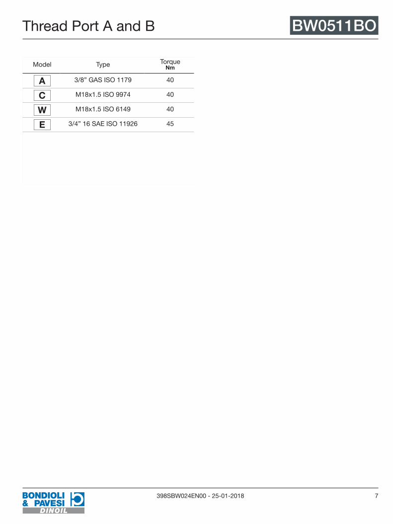
Thread Port A and B BW0511BO
Model Type Torque Nm
A 3/8” GAS ISO 1179 40
C M18x1.5 ISO 9974 40
W M18x1.5 ISO 6149 40
E 3/4” 16 SAE ISO 11926 45
Thread Port A and B

8 398SBW024EN00 - 25-01-2018
BW0511BO VL below A B
VL - Pressure limiting valve A port
P→AP→B
18 0.7172.7 2.86
MA
X 8
1.3
3.2
LS2
P2
T2
X (P→B) Y (P→A)
BA
P1
B A
T1
P2
1
T2
A0
T
BP
2
LS1 LS2
VL - Pressure limiting valve B port
P→AP→B
18 0.71 72.7 2.86
MA
X 8
1.3
3.2
LS2
P2
T2
X (P→B) Y (P→A)
BA
P1
B A
P2
T2T1
PT A
20
B1
LS1 LS2
VL below A B

9398SBW024EN00 - 25-01-2018
Valve type port A B BW0511BOVB Pilot check valve A port
P→AP→B
240.
94
25.4
1
31.5
1.24
190.
75
49.8 1.96 45.7 1.8 LS2
P2
T2
X (P→B) Y (P→A)
BA
P1
B A
T1
P2
1
T2
A0
T
BP
2
LS1 LS2
VB Pilot check valve B port
P→AP→B
45.7 1.8 49.8 1.96
240.
94
31.5
1.24
190.
75
25.4
1
LS2
P2
T2
X (P→B) Y (P→A)
BA
P1
B A
T1
P2
1
T2
A0
T
BP
2
LS1 LS2
NE Solenoid operated valve 2/2 port A
P→AP→B
652.
56
89.9 3.54 LS2
P2
T2
X (P→B) Y (P→A)
BA
P1
B A
T1
P2
T2
2
P B
T
0A
1
LS1 LS2
Valve type port A B

10 398SBW024EN00 - 25-01-2018
BW0511BO Valve type port A B
NE Solenoid operated valve 2/2 port B
P→AP→B
89.9 3.54
652.
56
LS2
P2
T2
X (P→B) Y (P→A)
BA
P1
B A
T1
P2
T2
2
P B
T
0A
1
LS1 LS2
FC One-way flow regulator port A
P→AP→B
31.5
1.24
190.
75
291.
14
77.7 3.06 LS2
P2
T2
A B
Y (P→A)X (P→B)
PT
2A
B1
P1
LS1
B A
T1 T2
P2
LS2
FC One-way flow regulator port B
P→AP→B
77.7 3.06
31.5
1.24
190.
75
291.
14
LS2
P2
T2
A B
Y (P→A)X (P→B)
PT
2A
B1
P1
LS1
B A
T1 T2
P2
LS2

11398SBW024EN00 - 25-01-2018
Valve type port A B BW0511BOVG VB piloted with two-way restrictor port A
P→AP→B
240.
94
45.8 1.863.5 2.5
31.5
1.24
190.
75
25.4
1
LS2
P2
T2
X (P→B) Y (P→A)
BA
P1
B A
T1
P2
T2
0A
PT
2B
1
LS1 LS2
VG VB piloted with two-way restrictor port A
P→AP→B
45.8 1.8 63.5 2.5
25.4
1
190.
75
240.
94
31.5
1.24LS2
P2
T2
X (P→B) Y (P→A)
BA
P1
B A
T1
P2
T2
0A
PT
2B
1
LS1 LS2
OV Over-center port A
P→AP→B
240.
94
190.
7531
.51.
24
26.5
1.04
102.7 4.04 45.8 1.8 LS2
P2
T2
X (P→B)
BA
Y (P→A)
2AT
B1
P
P1
LS1
B A
T1
LS2
P2
T2

12 398SBW024EN00 - 25-01-2018
BW0511BO Valve type port A B
OV Over-center port B
P→AP→B
31.5
1.24
190.
75
26.5
1.04
240.
94
102.7 4.0445.8 1.8LS2
P2
T2
X (P→B) Y (P→A)
BA2
AT
B1
P
P1
LS1
B A
T1
LS2
P2
T2
FP VB piloted with one-way restrictor port A
P→AP→B
240.
94
45.8 1.894.3 3.71
31.5
1.24
190.
75
26.5
1.04
LS2
P2
T2
X (P→B)
BA
Y (P→A)
A
PT
2B
1
P1
LS1
B A
T1
LS2
T2
P2
FP VB piloted with one-way restrictor port B
P→AP→B
45.8 1.8 94.3 3.71
31.5
1.24
190.
75
26.5
1.04
240.
94
LS2
P2
T2
X (P→B) Y (P→A)
A B
A
PT
2B
1
P1
LS1
B A
T1
LS2
T2
P2
13398SBW024EN00 - 25-01-2018
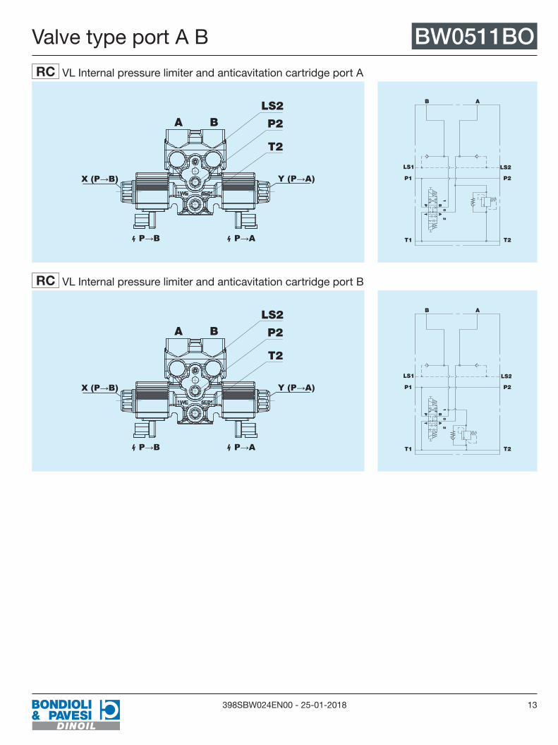
Valve type port A B BW0511BORC VL Internal pressure limiter and anticavitation cartridge port A
P→AP→B
LS2
P2
T2
A B
Y (P→A)X (P→B) P1
B A
T1
P2
1
T2
A0
T
BP
2
LS1 LS2
RC VL Internal pressure limiter and anticavitation cartridge port B
P→AP→B
LS2
P2
T2
A B
Y (P→A)X (P→B) P1
B A
T1
P2
1
T2
A0
T
BP
2
LS1 LS2

14 398SBW024EN00 - 25-01-2018
BW0511BO Valve type port A B
Possible valve combinations port A and BPort A Port B
NN VL VB NE FC VG OV FP RC
NN
VL
VB
NE
FC
VG
OV
FP
RC
NN - NoneFC - One-way flow regulatorVG - Pilot check valve with two-way
restrictorVB - Pilot check valveNE - Solenoid operated valve 2/2OV - Over-centerFP - Pilot check valve with one-way
restrictorVL - Pressure limiting valveRC - Internal pressure limiter and
anticavitation cartridge
15398SBW024EN00 - 25-01-2018
Valve type port A B BW0511BO

16 398SBW024EN00 - 25-01-2018
BW0511BO Ordering instructions
BW0511BO
1
2 3 4
5 6
7
8 9
10 11
12 13
14 15
16 17
18 19
20
21
1
Configurations Two coils, A and B port sideA One coil, A port sideE
One coil, B port sideF Two coils, A and B port side and emergency leverB
One coil, A port side and emergency leverC
One coil, B port side and emergency leverD
2 3 4
Spool types Spool type003
5 6
Flow rate ∆P = 18 bar 4 I/min - 1.06 US gpm0A 9 I/min - 2.37 US gpm0B 13 I/min - 3.43 US gpm0C
17 I/min - 4.49 US gpm0D 21 I/min - 5.54 US gpm0E 26 I/min - 6.87 US gpm0F
31 I/min - 8.19 US gpm0G 37 I/min - 9.77 US gpm0H 42 l/min - 11.1 US gpm0I
7
Thread Port A and B 3/8'' GAS ISO 1179A M18x1.5 ISO 9974C M18x1.5 ISO 6149W 3/4'' 16 SAE ISO 11926E
8 9
VL Pressure limiting valve below port A NoneNN VL 40 bar04 VL 50 bar05 VL 60 bar06 VL 70 bar07 VL 80 bar08
VL 90 bar09 VL 100 bar10 VL 110 bar11 VL 120 bar12 VL 130 bar13 VL 140 bar14
VL 150 bar15 VL 160 bar16 VL 170 bar17 VL 180 bar18 VL 190 bar19 VL 200 bar20
VL 210 bar21 VL 220 bar22 VL 230 bar23
10 11
VL Pressure limiting valve below port B NoneNN VL 40 bar04 VL 50 bar05 VL 60 bar06 VL 70 bar07 VL 80 bar08
VL 90 bar09 VL 100 bar10 VL 110 bar11 VL 120 bar12 VL 130 bar13 VL 140 bar14
VL 150 bar15 VL 160 bar16 VL 170 bar17 VL 180 bar18 VL 190 bar19 VL 200 bar20
VL 210 bar21 VL 220 bar22 VL 230 bar23
12 13
Port A valve type NoneNN One-way flow regulatorFC
Pilot check valveVB Pilot valve piloted with two-way restrictorVG
Pilot check valve with one-way restrictorFP
Solenoid operated valve 2/2NE Over-centerOV Internal pressure limiter and anticavitation cartridge
RC
14 15
OV/RC calibration pressure port A NoneNN 30 bar03 40 bar04 50 bar05 60 bar06 70 bar07 80 bar08
90 bar09 100 bar10 110 bar11 120 bar12 130 bar13 140 bar14 150 bar15
160 bar16 170 bar17 180 bar18 190 bar19 200 bar20 210 bar21 220 bar22
230 bar23 240 bar24 250 bar25 260 bar26 270 bar27
16 17
Valve type port B NoneNN One-way flow regulatorFC
Pilot check valveVB Pilot valve piloted with two-way restrictorVG
Pilot check valve with one-way restrictorFP
Solenoid operated valve 2/2NE Over-centerOV Internal pressure limiter and anticavitation cartridge
RC
Ordering instructions
17398SBW024EN00 - 25-01-2018
Ordering instructions BW0511BO
BW0511BO
1
2 3 4
5 6
7
8 9
10 11
12 13
14 15
16 17
18 19
20
21
1
Configurations Two coils, A and B port sideA One coil, A port sideE
One coil, B port sideF Two coils, A and B port side and emergency leverB
One coil, A port side and emergency leverC
One coil, B port side and emergency leverD
2 3 4
Spool types Spool type003
5 6
Flow rate ∆P = 18 bar 4 I/min - 1.06 US gpm0A 9 I/min - 2.37 US gpm0B 13 I/min - 3.43 US gpm0C
17 I/min - 4.49 US gpm0D 21 I/min - 5.54 US gpm0E 26 I/min - 6.87 US gpm0F
31 I/min - 8.19 US gpm0G 37 I/min - 9.77 US gpm0H 42 l/min - 11.1 US gpm0I
7
Thread Port A and B 3/8'' GAS ISO 1179A M18x1.5 ISO 9974C M18x1.5 ISO 6149W 3/4'' 16 SAE ISO 11926E
8 9
VL Pressure limiting valve below port A NoneNN VL 40 bar04 VL 50 bar05 VL 60 bar06 VL 70 bar07 VL 80 bar08
VL 90 bar09 VL 100 bar10 VL 110 bar11 VL 120 bar12 VL 130 bar13 VL 140 bar14
VL 150 bar15 VL 160 bar16 VL 170 bar17 VL 180 bar18 VL 190 bar19 VL 200 bar20
VL 210 bar21 VL 220 bar22 VL 230 bar23
10 11
VL Pressure limiting valve below port B NoneNN VL 40 bar04 VL 50 bar05 VL 60 bar06 VL 70 bar07 VL 80 bar08
VL 90 bar09 VL 100 bar10 VL 110 bar11 VL 120 bar12 VL 130 bar13 VL 140 bar14
VL 150 bar15 VL 160 bar16 VL 170 bar17 VL 180 bar18 VL 190 bar19 VL 200 bar20
VL 210 bar21 VL 220 bar22 VL 230 bar23
12 13
Port A valve type NoneNN One-way flow regulatorFC
Pilot check valveVB Pilot valve piloted with two-way restrictorVG
Pilot check valve with one-way restrictorFP
Solenoid operated valve 2/2NE Over-centerOV Internal pressure limiter and anticavitation cartridge
RC
14 15
OV/RC calibration pressure port A NoneNN 30 bar03 40 bar04 50 bar05 60 bar06 70 bar07 80 bar08
90 bar09 100 bar10 110 bar11 120 bar12 130 bar13 140 bar14 150 bar15
160 bar16 170 bar17 180 bar18 190 bar19 200 bar20 210 bar21 220 bar22
230 bar23 240 bar24 250 bar25 260 bar26 270 bar27
16 17
Valve type port B NoneNN One-way flow regulatorFC
Pilot check valveVB Pilot valve piloted with two-way restrictorVG
Pilot check valve with one-way restrictorFP
Solenoid operated valve 2/2NE Over-centerOV Internal pressure limiter and anticavitation cartridge
RC
Ordering instructions
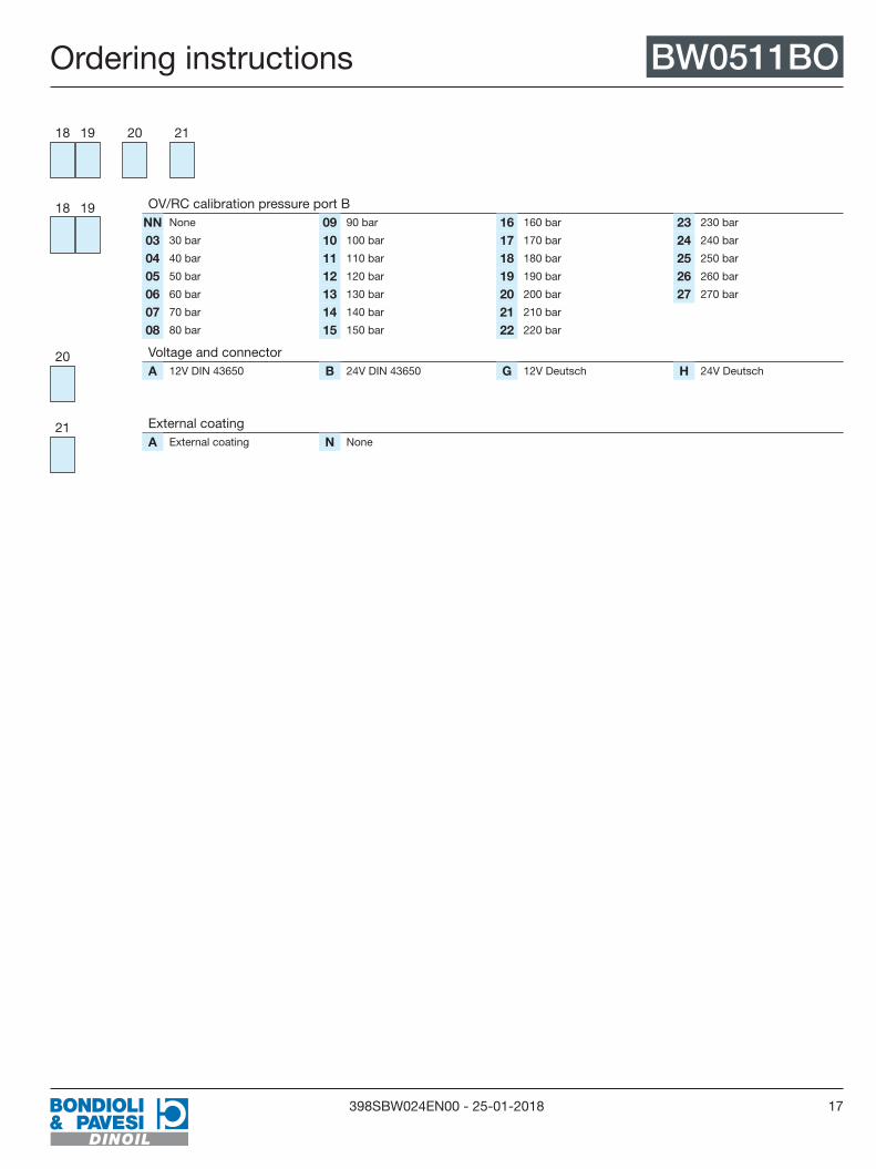
18 19
OV/RC calibration pressure port B NoneNN 30 bar03 40 bar04 50 bar05 60 bar06 70 bar07 80 bar08
90 bar09 100 bar10 110 bar11 120 bar12 130 bar13 140 bar14 150 bar15
160 bar16 170 bar17 180 bar18 190 bar19 200 bar20 210 bar21 220 bar22
230 bar23 240 bar24 250 bar25 260 bar26 270 bar27
20
Voltage and connector 12V DIN 43650A 24V DIN 43650B 12V DeutschG 24V DeutschH
21
External coating External coatingA NoneN