Embed Size (px)
DESCRIPTION
The CNGS Target Station Technical Study. By the Target Working Group Presented by L.Bruno AB/ATB Targets & Dumps Section. The CNGS Target Station. OUTLINE 1. Introduction 2. Shielding 3. Target Unit 4. Structural issues 5. Summary. Introduction - PowerPoint PPT Presentation
Citation preview

7-11 November 2003 NBI 2003 – CNGS Target StationPresentation by L.Bruno (CERN AB/ATB) 1
By the Target Working Group
Presented by L.BrunoAB/ATB Targets & Dumps Section
The CNGS Target Station
Technical Study

7-11 November 2003 NBI 2003 – CNGS Target StationPresentation by L.Bruno (CERN AB/ATB) 2
The CNGS Target Station
OUTLINE
1. Introduction 2. Shielding 3. Target Unit
4. Structural issues 5. Summary

7-11 November 2003 NBI 2003 – CNGS Target StationPresentation by L.Bruno (CERN AB/ATB) 3
Introduction (that is, what I will say and what I will NOT…)
Subjects covered in previous workshops
Driving parameters Conceptual design philosophy Target configuration and optimization
Subjects covered in THIS workshop Engineering design of the shielding Engineering design of the target New issues and developments

7-11 November 2003 NBI 2003 – CNGS Target StationPresentation by L.Bruno (CERN AB/ATB) 4
Layout - Vertical view
Target enclosure
Shield
Crane limit
Horn
lim
it
Horiz. Base plane
Target assembly
Steel frame
Proton beam
Fixed structure “Handled” structure

7-11 November 2003 NBI 2003 – CNGS Target StationPresentation by L.Bruno (CERN AB/ATB) 5
Layout - Front view
Passage
side
Cavern side
Target enclosure800x1400x3200 mm3
marb
le
Sid
e w
all
No access
Cap
Sid
e w
all
Sid
e w
all
Base
Iron shield
Proton beam

7-11 November 2003 NBI 2003 – CNGS Target StationPresentation by L.Bruno (CERN AB/ATB) 6
Target handling
Alignment table
Fiducials
Beam
Base table
Unit exchang
e mechani
sm
Collimator
BPKG monitor

7-11 November 2003 NBI 2003 – CNGS Target StationPresentation by L.Bruno (CERN AB/ATB) 7
Mobile shielding cap
Flat railGuiding rail
Passage
side
Cavern side
Manual Coupling
Quick disconne
ct

7-11 November 2003 NBI 2003 – CNGS Target StationPresentation by L.Bruno (CERN AB/ATB) 8
Mobile shielding – Top view
JacksBeam
Threaded shafts
Rail sections
Motor
Switches
Rail transition
Target magazin
e
BP
KG
C
ollim
ato
r

7-11 November 2003 NBI 2003 – CNGS Target StationPresentation by L.Bruno (CERN AB/ATB) 9
CouplingHorizontal
Motor
Beam
Slope 0.5%
Mobile shielding – Side view

7-11 November 2003 NBI 2003 – CNGS Target StationPresentation by L.Bruno (CERN AB/ATB) 10
Target AlignmentCourtesy of D.Missiaen
Passage
side
Cavern side
No access
Base
Proton beam
Alignment is based on: 2 horizontal bars for :
transversal alignment raw vertical alignment
2 vertical back-up bars used for accurate vertical alignment
Bars are: removable equipped with fiducials equipped with
clinometer ~1.2÷1.8 m long inclin. < 0.05/5 mrad
(H/V) provided with an
horizontalization system

7-11 November 2003 NBI 2003 – CNGS Target StationPresentation by L.Bruno (CERN AB/ATB) 11
Alignment by the horizontal bars Courtesy of D.Missiaen
Vertical measurementsperformed by means of an optical level using a deep reference and/or the adjacent components. Accuracy is not better than 0.15mm because of the bar inclination.
Horizontal measurementsDone by a motorized tacheometer driven by a PC. The operator is far from the area. Accuracy is in the range of 0.1 mm. The operator has to install and level the bar in a radioactive area (short time).
Note: vertical measurements can be improved to better that 0.1 mm accuracy by using the vertical bars. Access to the radioactive top shielding is restricted to long shut-downs
PC-driven tacheomete
r

7-11 November 2003 NBI 2003 – CNGS Target StationPresentation by L.Bruno (CERN AB/ATB) 12
Target handling
Alignment table
Fiducials
Beam
Base table
Unit exchang
e mechani
sm
Collimator
BPKG monitor

7-11 November 2003 NBI 2003 – CNGS Target StationPresentation by L.Bruno (CERN AB/ATB) 13
Target unit
DownstreamWindow
Target Support
Sealed finned tube
Inert gas
End cap
End cap
UpstreamWindo
w
The target unit is conceived as a static sealed system filled with inert gas. The tube has annular fins to enhance convective heat transfer. Light materials are used to limit the heat load.
MATERIALS
Tube: Al-Mg alloyWindows: Be by Brush & WellmanTarget Support: Carbon Fiber reinforced CarbonTarget rod: Fine-grain graphite
hexagonal boron nitride, CFC
Central tu
be

7-11 November 2003 NBI 2003 – CNGS Target StationPresentation by L.Bruno (CERN AB/ATB) 14
Unit Windows
St.Steel Aluminium alloy 5083
EB weld
B&W Be
window
(Ø1.5”)
B&W Be
window
(Ø4”)
Be-Al joint
Beam
7-11 November 2003 NBI 2003 – CNGS Target StationPresentation by L.Bruno (CERN AB/ATB) 15
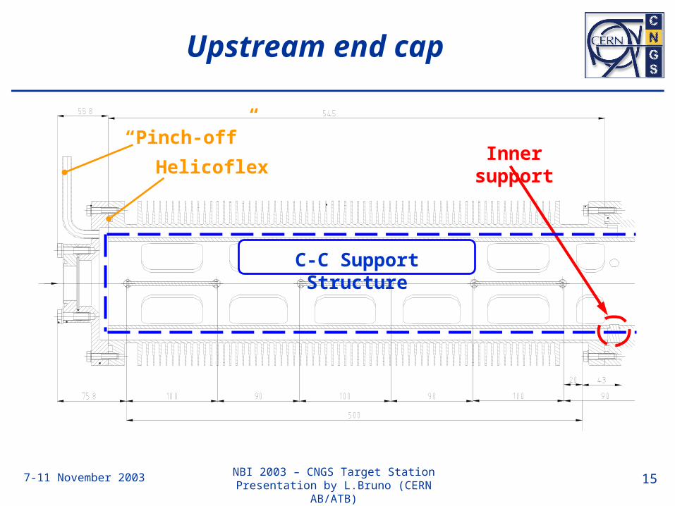
Upstream end cap
Inner support
C-C Support Structure
“Pinch-off”
Helicoflex

7-11 November 2003 NBI 2003 – CNGS Target StationPresentation by L.Bruno (CERN AB/ATB) 16
Central Tube
Inner supports
A-A B-B
A-A B-B
Outer suppo
rt
Outer suppo
rt
Reference
surface

7-11 November 2003 NBI 2003 – CNGS Target StationPresentation by L.Bruno (CERN AB/ATB) 17
Carbon Support Structure
Traversing rod supports
Inner supports
Cooling apertures
Common ref.
surface

7-11 November 2003 NBI 2003 – CNGS Target StationPresentation by L.Bruno (CERN AB/ATB) 18
Target elements – a new issue
New additional studies performed by an analytical model point out that…
If the target unit is cold (start-up)… and a first proton spill of ultimate intensity… hits the target with the worst misalignment… followed by a second, similarly misaligned spill… and stresses add up in the worst way ,
Then…

7-11 November 2003 NBI 2003 – CNGS Target StationPresentation by L.Bruno (CERN AB/ATB) 19
Maximum total stress [MPa]in a 2020PT graphite target rod
… unacceptable stresses are found

7-11 November 2003 NBI 2003 – CNGS Target StationPresentation by L.Bruno (CERN AB/ATB) 20
Target Material
hBN
0
13
26
39
52
65
78
0 200 400 600 800 1000
Temperature [°C]
Yo
un
g M
. [
GP
a]
/
σ
t [M
Pa]
-1
0
1
2
3
4
5
Cp
[kJ/
kg°C
]
α
[µm
/m °
C]
α┴
cp
E
σ4P
α||
Graphite
0
13
26
39
52
65
78
0 200 400 600 800 1000
Temperature [°C]
Yo
un
g M
. [
GP
a]
/
σ
t [M
Pa]
-1
0
1
2
3
4
5
Cp
[kJ/
kg°C
]
α
[µm
/m °
C]
α
cp
E
σ4P

7-11 November 2003 NBI 2003 – CNGS Target StationPresentation by L.Bruno (CERN AB/ATB) 21
Summary
Status in November 2003
1. The detailed design of the target station is being worked out;
2. The choice of the alignment procedure is being finalized;
3. The target assembly is being optimized (manufacturing, integration,…)
4. The interfaces for handling, cooling, beam instrumentation and alignment are being defined.
5. The worst-case stresses are presently an issue.

7-11 November 2003 NBI 2003 – CNGS Target StationPresentation by L.Bruno (CERN AB/ATB) 22
Twg TwgTwg
1st R
evie
w
Installation
Manufacturing
Technical study
Engineering study
2n
d R
evie
w
Conceptual design
Planning overview
2001 2002 2003 2004 2005

7-11 November 2003 NBI 2003 – CNGS Target StationPresentation by L.Bruno (CERN AB/ATB) 23
Target element