Embed Size (px)
Citation preview

CANNULATED PEDICLE SCREWROMEO®2 MIS
1
CANNU LATEDPEDICLE SCREW
B Y S P I N E A R T
ROMEO®2 MIS


CONTENT
CONCEPT AND DESIGN
IMPLANTS
TECHNICAL FEATURES
INSTRUMENT SET
INSTRUMENTS
SURGICAL TECHNIQUE
PAGE 04
PAGE 05
PAGE 06
PAGE 07
PAGE 09
PAGE 13
CANNULATED PEDICLE SCREWROMEO®2 MIS
3

CONCEPT AND DESIGN
INDICATIONS
The ROMEO®2 MIS system implants are indicated for patients presenting with the following pathologies: spondylolisthesis, degenerative disc disease, thoracic and lumbar fractures, thoracic and lumbar vertebra, stenosis and spine deformities (scoliosis, cyphosis).
AT A GLANCE
K-WIRELESS OPTION
STREAMLINED TIP
MICRO-OPEN AND/OR PERCUTANEOUS APPROACHES
SPONDYLOLISTHESIS REDUCTION
The first ROMEO®2 MIS surgery, performed in 2011, represents a milestone: a percutaneous procedure was performed without the need of Kirschner wires!The ROMEO®2 MIS system allows for 3 different options: pure percutaneous, bilateral mini-open and hybrid approach. A set of dedicated implants and versatile instruments makes the ROMEO®2 MIS the new standard in minimally invasive surgery.ROMEO®2 MIS combined with the first fully radiolucent posterior retractor OTELO®MIS, provides an innovative, efficient and safe Minimally Invasive platform. In each product development, Spineart is relentlessly driven by the same motto : Quality, Innovation, Simplicity.
ROMEO®2 MIS CANNULATED PEDICLE SCREW
4

IMPLANTS
LENGTH / DIAMETER
Ø5 Ø6 Ø7
L30 MIS-PS 05 30-S MIS-PS 06 30-S MIS-PS 07 30-S
L35 MIS-PS 05 35-S MIS-PS 06 35-S MIS-PS 07 35-S
L40 MIS-PS 05 40-S MIS-PS 06 40-S MIS-PS 07 40-S
L45 MIS-PS 05 45-S MIS-PS 06 45-S MIS-PS 07 45-S
L50 MIS-PS 05 50-S MIS-PS 06 50-S MIS-PS 07 50-S
L55 MIS-PS 06 55-S MIS-PS 07 55-S
L60 MIS-PS 06 60-S MIS-PS 07 60-S
CANNULATED POLYAXIAL SCREW2
PERCUTANEOUS ROD / PRE-BENT2 ø5.4
L30 MIS-RT 10 30-S
L35 MIS-RT 10 35-S
L40 MIS-RT 10 40-S
L45 MIS-RT 10 45-S
L50 MIS-RT 10 50-S
L55 MIS-RT 10 55-S
L60 MIS-RT 10 60-S
L65 MIS-RT 10 65-S
L70 MIS-RT 10 70-S
L75 MIS-RT 10 75-S
L80 MIS-RT 10 80-S
L85 MIS-RT 10 85-S
L90 MIS-RT 10 90-S
PERCUTANEOUS ROD / STRAIGHT1 2 ø5.4
L100 MIS-RT 01 00-S
L110 MIS-RT 01 10-S
L120 MIS-RT 01 20-S
L130 MIS-RT 01 30-S
L140 MIS-RT 01 40-S
L150 MIS-RT 01 50-S
L160 MIS-RT 01 60-S
L170 MIS-RT 01 70-S
L180 MIS-RT 01 80-S
L190 MIS-RT 01 90-S
L200 MIS-RT 02 00-S
L210 MIS-RT 02 10-S
L220 MIS-RT 02 20-S
L230 MIS-RT 02 30-S
L240 MIS-RT 02 40-S
L250 MIS-RT 02 50-S
1 Rods from 210 mm – 250 mm on demand.2 Implants can be delivered non sterile (MIS-PS XX XX-N, MIS-RT XX XX-N, ELL-SC 00 00-N)
SETSCREW2 ELL-SC 00 00-S
CANNULATED PEDICLE SCREWROMEO®2 MIS
5

TECHNICAL FEATURES
K-WIRELESS OPTION
• The K-Wireless option is designed to reduce intraoperative x-rays and the risk of a K-wire migration by simultaneously reducing the learning curve associated with common M.I.S. techniques
STREAMLINED TIP
• The screw tip allows for an effortless, self centering and K-Wireless screw insertion
MICRO-OPEN AND/OR PERCUTANEOUS APPROACHES
• The ROMEO®2 MIS system allows for bilateral micro-open, pure percutaneous or hybrid approaches to the thoracic junction and lumbar spine
SPONDYLOLISTHESIS REDUCTION
• The ROMEO®2 MIS system allows for bilateral, progressive, powerful and accurate spondylolisthesis reduction
ROMEO®2 MIS CANNULATED PEDICLE SCREW
6

INSTRUMENT SET
# DESCRIPTION REFERENCE
APPROACH RACK MIS-BX 10 02-N
TROCAR 3 IN 1
01 SQUARE AWL / DILATOR TUBE #1
MIS-IN 03 10-N
NEEDLE MIS-IN 03 15-N
T-HANDLE MIS-IN 03 14-N
02 TROCAR 3 IN 1 / TI STICK MIS-IN 03 16-N
03 K-WIRE IMPACTOR MIS-IN 38 00-N
04 DILATOR TUBE #2 MIS-IN 04 00-N
05 DILATOR TUBE #3 MIS-IN 05 00-N
06 DILATOR TUBE #4 /SERRATED
MIS-IN 06 02-N
07 DILATOR TUBE #5 MIS-IN 39 00-N
08 DILATOR TUBE #4 / SERRATED-PUSHER
MIS-IN 06 06-N
09 PEDICLE PROBE (K-WIRELESS) MIS-IN 34 00-N
# DESCRIPTION REFERENCE
SCREW INSERTION CONTAINER
MIS-BX 10 01-N
10 STRAIGHT HANDLE RATCHET HAN-SI RA ST-N
11 SCREWDRIVER SHAFT PS CANNULATED
MIS-IN 33 01-N
12 SCREWDRIVER TUBE ELL-IN 21 03-N
13 CLIPPING TUBE MIS-IN 17 01-N
14 CLIPPING TUBE OPEN MIS-IN 19 03-N
15 SETSCREW HOLDER W ELL-IN 03 10-N
16 UNIVERSAL TUBE MIS-IN 28 01-N
17 K-WIRE TUBE MIS-IN 30 00-N
K-WIRE W/BLUNT TIP MIS-IN 02 00-N
18 RELEASE TUBE MIS-IN 26 00-N
19 CENTERING GUIDE MIS-IN 45 00-N
01
02
13
09
14
08
16
03
10
19
04
05
1112
06
18
07
1715
APPROACH RACK
SCREW INSERTION CONTAINER
CANNULATED PEDICLE SCREWROMEO®2 MIS
7
INSTRUMENT SET
# DESCRIPTION REFERENCE
ROD MANIPULATION RACK MIS-BX 11 02-N
20 CALIPER MIS-IN 37 00-N
21 ROD INSERTER MIS-IN 35 02-N
22 ROD INSERTER PERCUTANEOUS
MIS-IN 40 01-N
23 PERSUADER MIS-IN 21 00-N
24 LOCKER MIS-IN 11 00-N
25 SETSCREW TIGHTENER ELL-IN 04 06-N
26 STABILIZER MIS-IN 29 00-N
27 ROD TEMPLATE ELL-IN 00 28-N
# DESCRIPTION REFERENCE
FINAL TIGHTENING CONTAINER
MIS-BX 11 01-N
28 ROD BENDER ELL-IN 00 09-N
29 COMPRESSION FORCEPS MIS-IN 41 00-N
30 DISTRACTION FORCEPS MIS-IN 42 00-N
31 T-HANDLE RATCHET HAN-SI RA TE-N
32 T-HANDLE HAN-SI MD TE-N
33 DYNAMOMETRIC TIGHTENER ELL-IN 03 06-N
23
25
32
31
24
21
22
28
26
33
27
29
20
30
ROD MANIPULATION RACK
FINAL TIGHTENING CONTAINER
ROMEO®2 MIS CANNULATED PEDICLE SCREW
8

INSTRUMENTSSQUARE AWL / DILATOR TUBE #1
MIS-IN 03 10-N DILATOR TUBE #2 MIS-IN 04 00-N
NEEDLE MIS-IN 03 15-N DILATOR TUBE #3 MIS-IN 05 00-N
T-HANDLE MIS-IN 03 14-N DILATOR TUBE #4 /SERRATED
MIS-IN 06 02-N
DILATOR TUBE #5 MIS-IN 39 00-N
K-WIRE IMPACTOR MIS-IN 38 00-N
PEDICLE PROBE (K-WIRELESS) MIS-IN 34 00-N
DILATOR TUBE #4 / SERRATED-PUSHER
MIS-IN 06 06-N
TROCAR 3IN1/TI STICK MIS-IN 03 16-N
CANNULATED PEDICLE SCREWROMEO®2 MIS
9

INSTRUMENTSSTRAIGHT HANDLE RATCHET HAN-SI RA ST-N K-WIRE TUBE MIS-IN 30 00-N
SCREWDRIVER SHAFT PS CANNULATED
MIS-IN 33 01-N K-WIRE W/BLUNT TIP MIS-IN 02 00-N
CLIPPING TUBE MIS-IN 17 01-N
CLIPPING TUBE OPEN MIS-IN 19 03-N
SETSCREW HOLDER W ELL-IN 03 10-N
RELEASE TUBE MIS-IN 26 00-N
CENTERING GUIDE MIS-IN 45 00-N
SCREWDRIVER TUBE ELL-IN 21 03-N
UNIVERSAL TUBE MIS-IN 28 01-N
ROMEO®2 MIS CANNULATED PEDICLE SCREW
10

INSTRUMENTSCALIPER MIS-IN 37 00-N
STABILIZER MIS-IN 29 00-N
ROD INSERTER MIS-IN 35 02-N
ROD TEMPLATE ELL-IN 00 28-N
ROD INSERTER PERCUTANEOUS
MIS-IN 40 01-N
PERSUADER MIS-IN 21 00-N
LOCKER MIS-IN 11 00-N
SETSCREW TIGHTENER ELL-IN 04 06-N
ROD BENDER ELL-IN 00 09-N COMPRESSION FORCEPS MIS-IN 41 00-N
CANNULATED PEDICLE SCREWROMEO®2 MIS
11

INSTRUMENTSDISTRACTION FORCEPS MIS-IN 42 00-N T-HANDLE RATCHET HAN-SI RA TE-N
T-HANDLE HAN-SI MD TE-NDYNAMOMETRIC TIGHTENER ELL-IN 03 06-N
ROMEO®2 MIS CANNULATED PEDICLE SCREW
12

FLUOROSCOPICORIENTATION
SURGICAL TECHNIQUE
Place the patient in the prone position on a radiolucent
surgical table.
To obtain optimal visualization of the spine, ensure
adequate clearance around the surgical table for the
fluoroscopic C-arm. It should be able to rotate freely
for AP, oblique and lateral views. Two C-arms can also
be used in AP and lateral views.
All other tools used for patient positioning should be
radiolucent too.
During the AP acquisition, verify that :
• the spinous processes are in the midline
• the endplates are linear
On the lateral view, verify that:
• the pedicles are superimposed
• the endplates are linear
Adjust the C-arm according to the lordosis of the
vertebra level on the lateral image.
Note: It is important to start with a clear radiographic
image in order to avoid any parallax distortion.
Midline oriented spinous process
Good exposure of pedicles
CANNULATED PEDICLE SCREWROMEO®2 MIS
13

SURGICAL TECHNIQUESTEP 1
TROCAR 3 IN 1 ASSEMBLY
The Trocar 3in1 consists of:
01. Trocar 3 in 1 / Square awl / dilator tube # 1
02. Trocar 3 in 1 / Needle
03. Trocar 3 in 1 / T-handle
04. Trocar 3 in 1 / Ti stick
Place the T-Handle onto the proximal (threaded side)
of the Square awl / dilator tube #1. The part will slide
into position, no screwing is required.
Place the Needle into the proximal part of the
assembly. Fix it by threading the knob until locked
into place.
Place the stick into the lateral end of the T-handle and
fix by mating the threaded parts together.
Note: The Trocar 3 in 1 is used to create a path down
the pedicle.
INSTRUMENT REFERENCE
TROCAR 3 in 1
SQUARE AWL / DILATOR TUBE #1
MIS-IN 03 10-N
NEEDLE MIS-IN 03 15-N
T-HANDLE MIS-IN 03 14-N
TI STICK MIS-IN 03 16-N
01 02
04
03
01
0203
04
ROMEO®2 MIS CANNULATED PEDICLE SCREW
14

STEP 2
SURGICAL TECHNIQUE
PEDICLE TARGETING
Dock the Trocar 3 in 1 onto the superior lateral halves
of the pedicle – Position 1 - on the AP view. Hold onto
the Trocar 3 in 1 / Ti stick during fluoroscopy in order
to keep hands out of the x-ray field.
Using biplanar fluoroscopy, the trocar is inserted into
the pedicle. Make sure that distal part of the Trocar 3
in 1 is lateral to the medial wall of the pedicle to ensure
that the Trocar 3 in 1 is in the safe zone – Position 2.
The entry point into the vertebral body - Position 3 –
is located just at the limit of the safe zone following
the trajectory either before.
Make adjustments using fluoroscopy.
Note: The Trocar 3 in 1 / square awl / dilator tube #1
has a depth-stop at 20 mm (22 mm total with the
trocar needle) to limit the entry point depth.
At this point the surgeon must decide whether to use the K-wire or K-wireless technique.
0102
03
01
0203
AP view
Lateral view
Axial view
INSTRUMENT REFERENCE
TROCAR 3 in 1
SQUARE AWL / DILATOR TUBE #1
MIS-IN 03 10-N
NEEDLE MIS-IN 03 15-N
T-HANDLE MIS-IN 03 14-N
TI STICK MIS-IN 03 16-N
CANNULATED PEDICLE SCREWROMEO®2 MIS
15

SURGICAL TECHNIQUESTEP 3
SEQUENTIAL DILATION
Carefully detach the Needle and T-handle from Trocar 3 in 1.
Start sequential dilation over Trocar 3 in 1 using Dilator tubes #2, #3, #4/serrated.
Advance all dilator tubes until black ring markings are clearly visible.
Place the Dilator tube #4/serrated-pusher over the Dilator tube #4/serrated top.Lightly hammer the Dilator tube#4/serrated in order to firmly attach it to the bony structure.
At this step, it’s recommended to remove the Serrated-pusher.
Screw the lateral side of the T-handle on the proximal side of the Square awl/dilator tube #1, and pull to remove Dilator tubes #1 to #3.
Note: It’s important to keep the Dilator tube #4/serrated steady.
K-wire technique: Remove the Needle and the T-handle to allow the K-wire to be inserted into the pedicle.
Place the K-wire impactor over the K-wire and use a hammer to impact the K-wire.
Use AP and Lateral fluoroscopy to confirm K-wire placement.
Remove the K-wire impactor.
INSTRUMENT REFERENCE
DILATOR TUBE #2 MIS-IN 04 00-N
DILATOR TUBE #3 MIS-IN 05 00-N
DILATOR TUBE #4 / SERRATED MIS-IN 06 02-N
DILATOR TUBE #4 / SERRATED-PUSHER
MIS-IN 06 06-N
TROCAR 3 IN 1
K-WIRE IMPACTOR MIS-IN 38 00-N
ROMEO®2 MIS CANNULATED PEDICLE SCREW
16
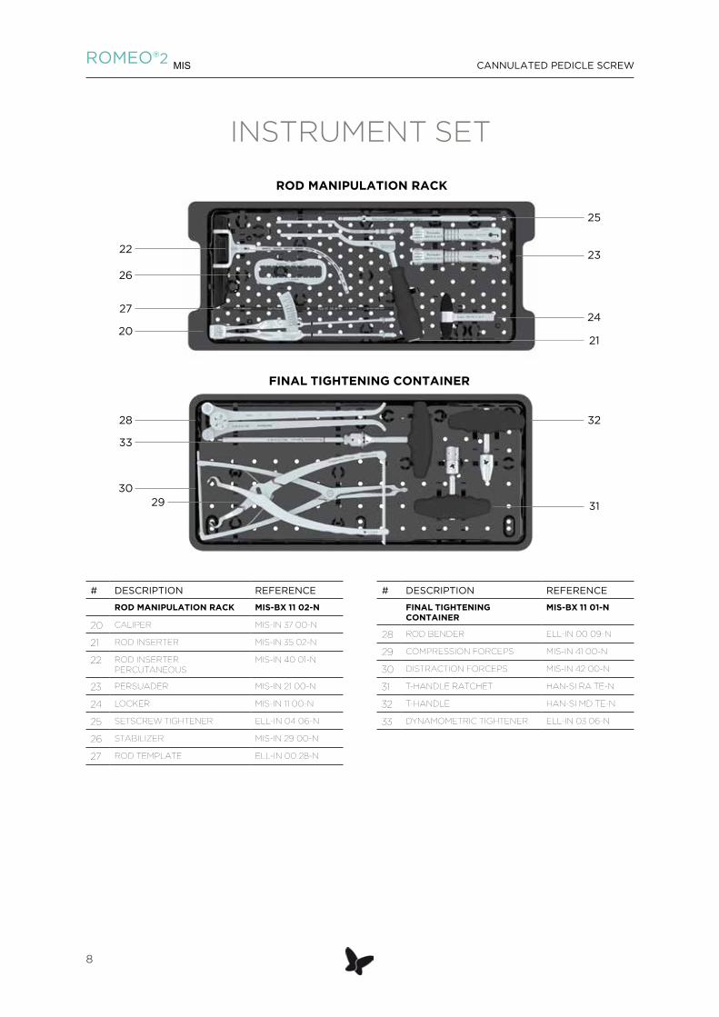
STEP 4
SURGICAL TECHNIQUE
PEDICLE PREPARATION
Introduce the Pedicle probe (K-wireless) through
Dilator tube #4 / serrated, the instrument is self-
aligning. Prepare the pedicle canal by placing the
pedicle probe distal tip curvature in a medial position.
Carry out AP and lateral controls under fluoroscopy
during pedicle preparation maneuver.
The scaled graduation indicates the progression of
the distal tip of the instrument into the pedicle canal.
Note: It’s recommended to assemble the pedicle
screw with the screwdriver before removing the
pedicle probe.
INSTRUMENT REFERENCE
PEDICLE PROBE (K-WIRELESS) MIS-IN 34 00-N
DILATOR TUBE #4 SERRATED MIS-IN 06 02-N
CANNULATED PEDICLE SCREWROMEO®2 MIS
17

SURGICAL TECHNIQUESTEP 5
SCREWDRIVER ASSEMBLY
The Screwdriver consists of:
01. Screwdriver shaft PS cannulated
02. Screwdriver tube
03. Straight handle ratchet (or T-handle ratchet)
Slide the Screwdriver shaft PS cannulated into the Screwdriver tube until it clicks.
Connect the assembly to the handle option, e.g straight handle ratchet.
INSTRUMENT REFERENCE
STRAIGHT HANDLE RATCHET HAN-SI RA ST-N
T-HANDLE RATCHET HAN-SI RA TE-N
SCREWDRIVER TUBE ELL-IN 21 03-N
SCREWDRIVER SHAFT PS CANNULATED
MIS-IN 33 01-N
01
02
03
ROMEO®2 MIS CANNULATED PEDICLE SCREW
18

STEP 6
SURGICAL TECHNIQUE
PEDICLE SCREW ASSEMBLY
Engage the screw head (02) to the Clipping tube
open (01) or Clipping tube until it clicks.
Insert the Screwdriver (03) through the assembly and
engage its distal tip into the screw.
Rotate the knob clockwise to engage the Screwdriver
to the screw.
INSTRUMENT REFERENCE
CLIPPING TUBE (SPONDYLO OR TRAUMA)
MIS-IN 17 01-N
CLIPPING TUBE OPEN MIS-IN 19 03-N
SCREWDRIVER
01
02
03
CANNULATED PEDICLE SCREWROMEO®2 MIS
19
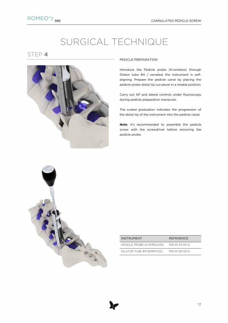
SURGICAL TECHNIQUESTEP 7
PEDICLE SCREW INSERTION
Keep the Dilator tube #4/serrated steady.
Remove the Pedicle probe (K-wireless) from the
vertebra and advance the assembly through the
Dilator tube #4/serrated.
Note: Continue to advance the screw until the black
line on the selected Clipping tube reaches the proximal
end of the Dilator tube#4/serrated to ensure that the
screw has passed the Dilator tube.
Confirm the advancement of the screw down the
proper trajectory by using fluoroscopy.
Remove the Screwdriver.
Verify polyaxial capability by manipulating the
Clipping tube.
Repeat the steps for each pedicular screw.
K-wire technique: Place assembly over the K-wire
and advance through the Dilator tube #4/serrated.
Use fluoroscopy to confirm that the K-wire has not
advance or retract. Advance the screw to the desired
depth and confirm with fluoroscopy.
Remove the K-wire and the Screwdriver.
INSTRUMENT REFERENCE
DILATOR TUBE #4/ SERRATED MIS-IN 06 02-N
CLIPPING TUBE OPEN MIS-IN 19 03-N
CLIPPING TUBE MIS-IN 17 01-N
SCREWDRIVER
K-WIRE W/BLUNT TIP MIS-IN 02 00-N
ROMEO®2 MIS CANNULATED PEDICLE SCREW
20

STEP 8
SURGICAL TECHNIQUE
ROD MEASURING
Insert the Caliper into the craniocaudal Clipping tubes.
Push the Caliper down until fully seated in the screw
heads.
Read the exact rod length on the laser etched scale.
For accuracy in measurement, be sure that the
Clipping tubes are vertically positioned.
INSTRUMENT REFERENCE
CALIPER MIS-IN 37 00-N
ROD TEMPLATE ELL-IN 00 28-N
CLIPPING TUBE MIS-IN 17 01-N
CLIPPING TUBE OPEN MIS-IN 19 03-N
CANNULATED PEDICLE SCREWROMEO®2 MIS
21

SURGICAL TECHNIQUESTEP 9
ROD INSERTER ASSEMBLY
Choose either the Rod inserter or the Rod inserter percutaneous.
For Rod inserter MIS-IN 35 02-N
Assemble the Rod inserter by inserting the inner bayonetted shaft into the main bayonetted shaft (01) and screwing the upper knob past the first set of threads (02) .
Align the laser marked lines of the square end of the rod and distal end of the Rod Inserter. Place the square feature of the rod into the square feature of the distal tip of the Rod Inserter, and screw the thumb screw of the Rod inserter by hand to fix into place.
Note: Tighten the screw on top of the Rod inserter to ensure that the rod is securely attached.
INSTRUMENT REFERENCE
ROD INSERTER MIS-IN 35 02-N
01
02
ROMEO®2 MIS CANNULATED PEDICLE SCREW
22

SURGICAL TECHNIQUESTEP 9 bis
ROD INSERTER ASSEMBLY
For Rod inserter Percutaneous MIS-IN 40 01-N
LOCK THE ROD: from «released position» to «locked position»• The Rod Inserter Percutaneous is on the
«released» position.• Turn the button and release it down: introduce
the rod so that the rod laser marking and the instrument’s laser marking are facing each other.
• Pull-up the button: the clamp retracts itself and the rod is captured.
• Lock the rod: turn the button so that the «locked» arrow laser marking is aligned on the handle laser marking. The rod is tightened to the Rod Inserter in «locked» position and ready to be introduced.
• Verify the secure attachment of the rod.
Note: The estimated rod entry point is at 80 mm from the first Clipping tube.
RELEASE THE ROD IN SITU: from «locked position» to «released position»• The Rod Inserter Percutaneous is on the «locked»
position with the rod attached.• Turn the button in down position: the clamp goes
out and releases the rod.• Place the button on «Released» position and take
off the instrument.
INSTRUMENT REFERENCE
ROD INSERTER PERCUTANEOUS
MIS-IN 40 01-N
Position RELEASED
Position LOCKED
Handle laser marking
Rod Inserter Percutaneous laser marking to index the rod during its
connexion
Button «locked up» position or «released down» position
CANNULATED PEDICLE SCREWROMEO®2 MIS
23

STEP 10
SURGICAL TECHNIQUE
ROD INSERTION
Attach the appropriate rod to the selected Rod
inserter.
Pass the rod through the outer Clipping tube.
Note: The stabilizer can be used additionally in order
to realign the Clipping tubes.
Confirm the good position of the rod by fluoroscopy.
Place the Universal tubes in the Clipping tubes in
order to seat the rod into screw heads.
The rod should be locked down with at least one setscrew before disconnecting the Rod inserter so the rod can not move or lose its lordotic angle.
INSTRUMENT REFERENCE
UNIVERSAL TUBE MIS-IN 28 01-N
ROD INSERTER MIS-IN 35 02-N
ROD INSERTER PERCUTANEOUS
MIS-IN 40 01-N
STABILIZER MIS-IN 29 00-N
ROMEO®2 MIS CANNULATED PEDICLE SCREW
24

STEP 10 (optional)
SURGICAL TECHNIQUE
ROD REDUCTION
The Persuader can be used to reduce the rod into the
screw head, making setscrew placement easier.
Place the Persuader (02) in open position (read
marking « 20 ») onto the Clipping tube with Universal
tube in place (01).
Lock the Persuader on the Clipping tube by turning
it clockwise, until the opening matches with the laser
etched point.
Start reduction by turning the threaded knob
clockwise.
INSTRUMENT REFERENCE
PERSUADER MIS-IN 21 00-N
CLIPPING TUBE MIS-IN 17 01-N
CLIPPING TUBE OPEN MIS-IN 19 03-N
UNIVERSAL TUBE MIS-IN 28 01-N
01
02
CLOSED POSITION
CANNULATED PEDICLE SCREWROMEO®2 MIS
25

SURGICAL TECHNIQUESTEP 10 (optional)
SPONDYLOLISTHESIS REDUCTION
Place the Universal tubes into the Clipping tubes and attach the Persuader in open position onto the contralateral and ipsilateral Clipping tube of the slipped vertebral body.
Lock the Persuaders on the Clipping tubes.
Start parallel reduction by turning the threaded knobs of the Persuaders clockwise. Use the Locker to support the reduction process.
Note: The reduction maneuver can be performed bilaterally and simultaneously.
Verify the reduction under fluoroscopic control.
Carry out the preliminary tightening maneuver once the desired reduction has been achieved as described STEP 11.
INSTRUMENT REFERENCE
PERSUADER MIS-IN 21 00-N
UNIVERSAL TUBE MIS-IN 28 01-N
CLIPPING TUBE MIS-IN 17 01-N
CLIPPING TUBE OPEN MIS-IN 19 03-N
SETSCREW HOLDER W ELL-IN 03 10-N
LOCKER MIS-IN 11 00-N
ROMEO®2 MIS CANNULATED PEDICLE SCREW
26

STEP 11
SURGICAL TECHNIQUE
PRELIMINARY TIGHTENING
Load the Setscrew to the self-retaining distal tip of the
Setscrew holder W.
Advance the setscrew through the Universal tube, or
the Persuader if used.
Tighten by hand.
Repeat for all pedicle screws in the construct.
Remove the Persuader if applicable.
INSTRUMENT REFERENCE
SETSCREW HOLDER W (SELF-RETAINING)
ELL-IN 03 10-N
UNIVERSAL TUBE MIS-IN 28 01-N
LOCKER MIS-IN 11 00-N
STABILIZER MIS-IN 29 00-N
PERSUADER MIS-IN 21 00-N
CANNULATED PEDICLE SCREWROMEO®2 MIS
27

STEP 12 (optional)
SURGICAL TECHNIQUE
COMPRESSION AND DISTRACTION
Attach the Stabilizer onto the Clipping tubes in order
to realign them.
Verify that the Universal tubes are in place.
Note: Prior to any compression or distraction
maneuver, lock the setscrew at the extremity of the
construct.
Insert the Dynamometric tightener into one of the
craniocaudal Universal tube and attach the hexagonal
tip of the instrument to the setscrew in order to
generate a more rigid construct.
Apply the desired pressure to the Clipping tubes and
maintain through the next step, final tightening.
INSTRUMENT REFERENCE
DYNAMOMETRIC TIGHTENER ELL-IN 03 06-N
COMPRESSION FORCEPS MIS-IN 41 00-N
STABILIZER MIS-IN 29 00-N
DISTRACTION FORCEPS MIS-IN 42 00-N
UNIVERSAL TUBE MIS-IN 28 01-N
SETSCREW HOLDER W ELL-IN 03 10-N
ROMEO®2 MIS CANNULATED PEDICLE SCREW
28

SURGICAL TECHNIQUESTEP 13
FINAL TIGHTENING
Finally tighten the setscrews with the Dynamometric tightener in combination with the Stabilizer.
Remove the Compression forceps or the Distraction forceps if applicable.
INSTRUMENT REFERENCE
STABILIZER MIS-IN 29 00-N
DYNAMOMETRIC TIGHTENER ELL-IN 03 06-N
CANNULATED PEDICLE SCREWROMEO®2 MIS
29
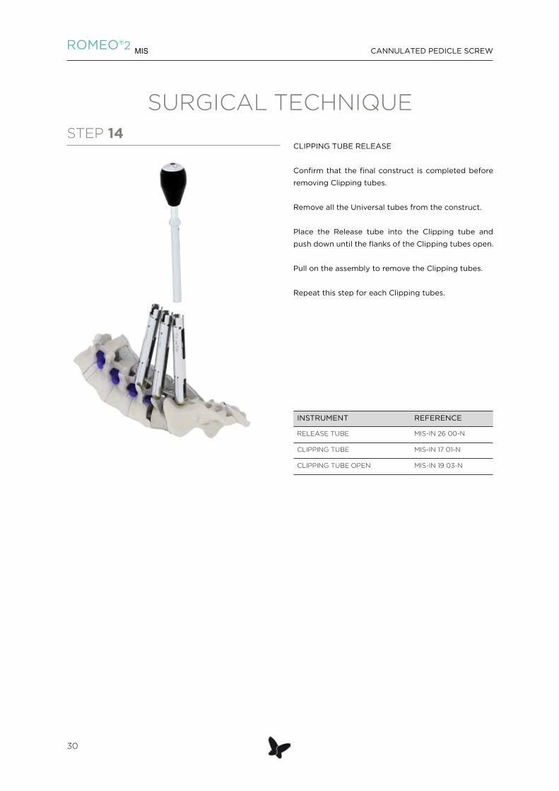
SURGICAL TECHNIQUESTEP 14
CLIPPING TUBE RELEASE
Confirm that the final construct is completed before
removing Clipping tubes.
Remove all the Universal tubes from the construct.
Place the Release tube into the Clipping tube and
push down until the flanks of the Clipping tubes open.
Pull on the assembly to remove the Clipping tubes.
Repeat this step for each Clipping tubes.
INSTRUMENT REFERENCE
RELEASE TUBE MIS-IN 26 00-N
CLIPPING TUBE MIS-IN 17 01-N
CLIPPING TUBE OPEN MIS-IN 19 03-N
ROMEO®2 MIS CANNULATED PEDICLE SCREW
30

SURGICAL TECHNIQUE
RE-ATTACHING CLIPPING TUBES
Insert the Dilator tube #5 to expose the screw head.
Introduce the distal end of the Centering guide
through the Dilator tube #5 until fully seated in the
screw head.
Insert the Clipping tube along the guide tracks of the
Centering guide.
Push on the Clipping tube and connect it to the screw
head until it clicks.
Remove the Centering guide.
INSTRUMENT REFERENCE
CENTERING GUIDE MIS-IN 45 00-N
CLIPPING TUBE MIS-IN 17 01-N
CLIPPING TUBE OPEN MIS-IN 19 03-N
DILATOR TUBE #5 MIS-IN 39 00-N
CANNULATED PEDICLE SCREWROMEO®2 MIS
31

FINAL CONSTRUCT
SURGICAL TECHNIQUE
ROMEO®2 MIS CANNULATED PEDICLE SCREW
32

NOTE
CANNULATED PEDICLE SCREWROMEO®2 MIS
33

NOTE
ROMEO®2 MIS CANNULATED PEDICLE SCREW
34


ROMEO®2 MIS CANNULATED PEDICLE SCREW
36
spineart.com
SPINEART SA 20 route de Pré-Bois1215 Geneva 15Switzerland
SPINEART USA227 East 58th St. 2nd FloorNew York, NY 10022 United States of America
9200 Irvine Center Drive, Suite 150Irvine, CA 92618United States of America
1250
011
5-V
2 re
f. M
IS-B
R 0
2 31
- E
S W I S S M A D E