Embed Size (px)
Citation preview
by
Roger Pynn
Lectures 11: Neutron Spin Echo
The Goal of Neutron Spin Echo is to Break the Inverse Relationship between Intensity & Resolution
• Traditional – define both incident & scattered wavevectors in order to define E and Q accurately
• Traditional – use collimators, monochromators, choppers etc to define both ki and kf
• NSE – measure as a function of the difference between appropriate components of ki and kf (original use: measure ki – kf i.e. energy change)
• NSE – use the neutron’s spin polarization to encode the difference between components of ki and kf
• NSE – can use large beam divergence &/or poor monochromatization to increase signal intensity, while maintaining very good resolution
The Principles of NSE are Very Simple
• If a spin rotates anticlockwise & then clockwise by the same amount it comes back to the same orientation– Need to reverse the direction of the applied field– Independent of neutron speed provided the speed is constant
• The same effect can be obtained by reversing the precession angle at the mid-point and continuing the precession in the same sense– Use a π rotation
• If the neutron’s velocity, v, is changed by the sample, its spin will not come back to the same orientation– The difference will be a measure of the change in the neutron’s speed or
energy
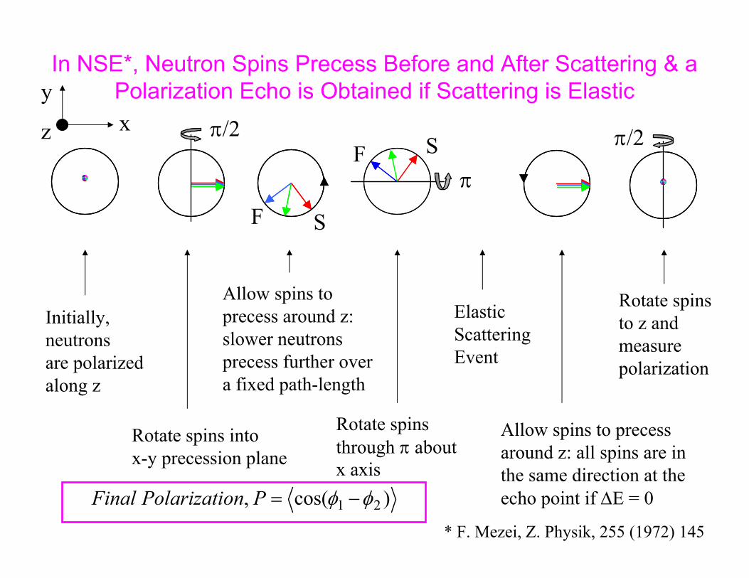
In NSE*, Neutron Spins Precess Before and After Scattering & a Polarization Echo is Obtained if Scattering is Elastic
Initially, neutronsare polarizedalong z
Rotate spins intox-y precession plane
Allow spins toprecess around z: slower neutrons precess further overa fixed path-length
Rotate spins through π aboutx axis
Elastic ScatteringEvent
Allow spins to precessaround z: all spins are in the same direction at the echo point if ΔE = 0
Rotate spinsto z andmeasurepolarization
SF
SFπ/2
π
π/2
)cos( , 21 φφ −=PonPolarizatiFinal
yxz
* F. Mezei, Z. Physik, 255 (1972) 145
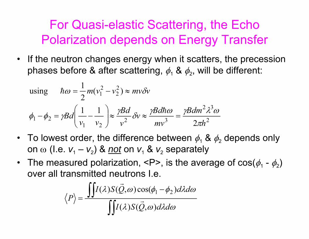
For Quasi-elastic Scattering, the Echo Polarization depends on Energy Transfer
• If the neutron changes energy when it scatters, the precession phases before & after scattering, φ1 & φ2, will be different:
• To lowest order, the difference between φ1 & φ2 depends only on ω (I.e. v1 – v2) & not on v1 & v2 separately
• The measured polarization, <P>, is the average of cos(φ1 - φ2) over all transmitted neutrons I.e.
2
32
3221
21
22
21
211
)(21 using
hBdm
mvBdv
vBd
vvBd
vmvvvm
πωλγωγδγγφφ
δω
=≈≈⎟⎟⎠
⎞⎜⎜⎝
⎛−=−
≈−=
h
h
∫∫∫∫ −
=ωλωλ
ωλφφωλ
ddQSI
ddQSIP
),()(
)cos(),()( 21r
r

Neutron Polarization at the Echo Point is a Measure of the Intermediate Scattering Function
• I(Q,t) is called the intermediate scattering function– Time Fourier transform of S(Q,ω) or the Q Fourier transform of G(r,t), the two
particle correlation function
• NSE probes the sample dynamics as a function of time rather thanas a function of ω
• The spin echo time, τ, is the “correlation time”
32
2
21
2 time"echospin " thewhere
) )cos(),(),()(
)cos(),()(
λπ
γτ
ωωτωωλωλ
ωλφφωλ
hmBd
,τQI(dQSddQSI
ddQSIP
=
=≈−
= ∫∫∫∫∫ rr
r
r
1861.01400.61120.41
τ(ns)
λ (nm)
Bd(T.m)

What does a NSE Spectrometer Look Like?IN11 at ILL was the First
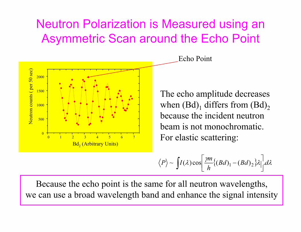
Neutron Polarization is Measured using an Asymmetric Scan around the Echo Point
0 1 2 3 4 5 6 70
500
1000
1500
2000
Neu
tron
coun
ts (
per 5
0 se
c)
Current in coil 30 1 2 3 4 5 6 7
0
500
1000
1500
2000
Neu
tron
coun
ts (
per 5
0 se
c)
Bd2 (Arbitrary Units)
The echo amplitude decreases when (Bd)1 differs from (Bd)2because the incident neutron beam is not monochromatic. For elastic scattering:
{ } λλγλ dBdBdhmIP .)()(cos)(~ 21∫ ⎥⎦
⎤⎢⎣⎡ −
Echo Point
Because the echo point is the same for all neutron wavelengths,we can use a broad wavelength band and enhance the signal intensity
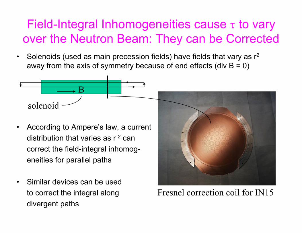
Field-Integral Inhomogeneities cause τ to vary over the Neutron Beam: They can be Corrected
• Solenoids (used as main precession fields) have fields that vary as r2
away from the axis of symmetry because of end effects (div B = 0)
• According to Ampere’s law, a current distribution that varies as r 2 can correct the field-integral inhomog-eneities for parallel paths
• Similar devices can be usedto correct the integral alongdivergent paths
Fresnel correction coil for IN15
B
solenoid
0 .001 0 .01 0 .1 1 10 100Q (Å-1)
Ene
rgy
Tran
sfer
(meV
)
Ne utro ns in Co nde ns e d Matte r Re s e arc h
S pa lla tio n - Ch opp er ILL - w ithou t s p in -ec ho ILL - w ith s p in -e ch o
Crystal Fields
Spin Waves
Neutron Induced
ExcitationsHydrogen Modes
Molecu lar Vibrations
Lattice Vibrations
and Anharmonicity
Aggregate Motion
Polymers and
Biological Systems
Critical Scattering
Diffusive Modes
Slower Motions
Resolved
Molecular Reorientation
Tunneling Spectroscopy
Surface Effects?
[Larger Objects Resolved]
Proteins in Solution Viruses
Micelles PolymersMetallurgical
SystemsColloids
Membranes Proteins
C rystal and Magnetic
StructuresAmorphous
Systems
Accurate Liquid StructuresP recision Crystallography
Anharmonicity
1
100
10000
0.01
10-4
10-6
Momentum DistributionsElastic Scattering
Electron- phonon
Interactions
Itinerant Magnets
Molecular Motions
Coherent Modes in Glasses
and Liquids
SPSS - Chopper Spectrometer
Neutron Spin Echo has significantly extended the (Q,E) range to which neutron scattering can be applied
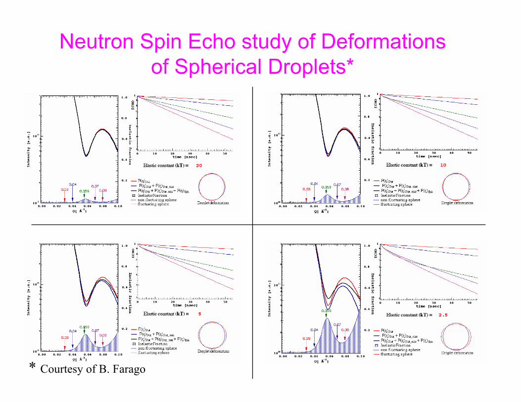
Neutron Spin Echo study of Deformations of Spherical Droplets*
* Courtesy of B. Farago
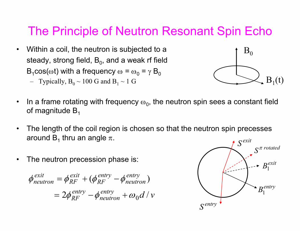
• Within a coil, the neutron is subjected to a steady, strong field, B0, and a weak rf field B1cos(ωt) with a frequency ω = ω0 = γ B0
– Typically, B0 ~ 100 G and B1 ~ 1 G
• In a frame rotating with frequency ω0, the neutron spin sees a constant field of magnitude B1
• The length of the coil region is chosen so that the neutron spin precessesaround B1 thru an angle π.
• The neutron precession phase is:
The Principle of Neutron Resonant Spin Echo
B1(t)
B0
vdentryneutron
entryRF
entryneutron
entryRF
exitRF
exitneutron
/2
)(
0ωφφ
φφφφ
+−=
−+=entryB1
entryS
rotatedS π
exitB1
exitS
�
����� �� ���� ��������
���� ��� ���� �� ������ ���� ���� �
� �� ��� �
�� ��� � �� � ��
���� ���� � ���
� �� � �� � �����
�
��� ���� � ���
�� ��� � �� � ������
�
���� �� �����
�
� �� ���� �� �����
�
�� ��� � �� � ��
����� ��
���
� ���� � �� �����
�
� �� � �� � �����
��
���� ��
���
� ���� � �� �����
�
�� ��� � �� � ������
��
����� ��� ������
�
�����
��
�
NRSE spectrometer
B=0
tA tA’ t tB
+ + + +d lAB
B= B=0
tC tC’ t tD
+ + + +
B=0Sample
A B C D
B0 B0nB0B0
d d dlCD
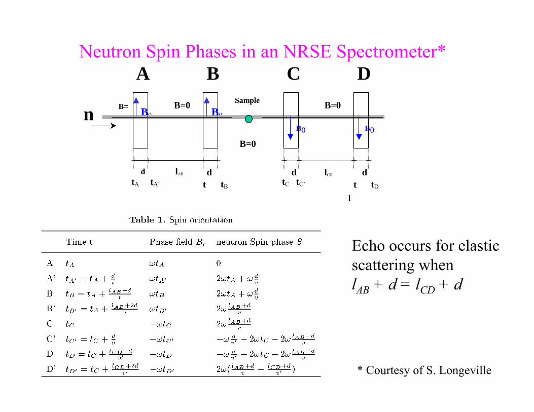
Echo occurs for elastic scattering when lAB + d = lCD + d
Neutron Spin Phases in an NRSE Spectrometer*
* Courtesy of S. Longeville
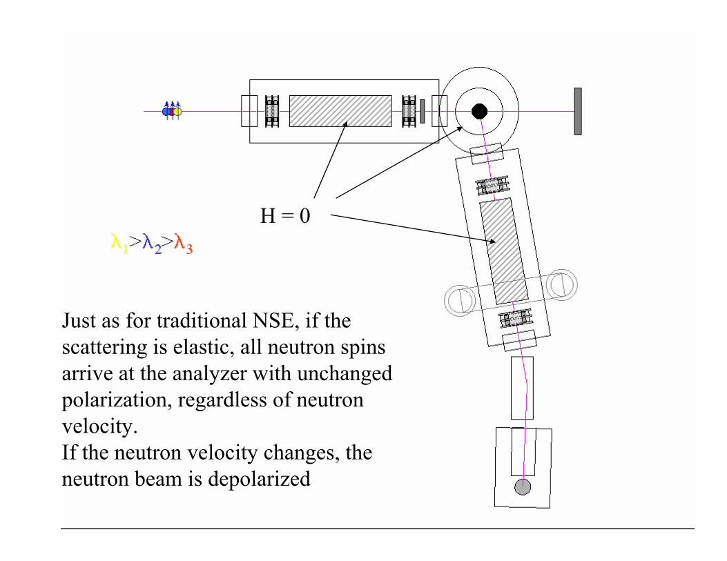
H = 0
Just as for traditional NSE, if the scattering is elastic, all neutron spins arrive at the analyzer with unchanged polarization, regardless of neutron velocity. If the neutron velocity changes, the neutron beam is depolarized

The Measured Polarization for NRSE is given by an Expression Similar to that for Classical NSE
• Assume that v’ = v + δv with δv small and expand to lowest order, giving:
• Note the additional factor of 2 in the echo time compared with classical NSE (a factor of 4 is obtained with “bootstrap” rf coils)
• The echo is obtained by varying the distance, l, between rf coils
• In NRSE, we measure neutron velocity using fixed “clocks” (the rf coils) whereas in NSE each neutron “carries its own clock” whose (Larmor) rate is set by the local magnetic field
32
2
0 2)(2 time"echospin " thewhere
),()(
)cos(),()(
λπ
γτ
ωλωλ
ωλωτωλ
hmdlB
ddQSI
ddQSIP
NRSE
NRSE
+=
=∫∫
∫∫r
r
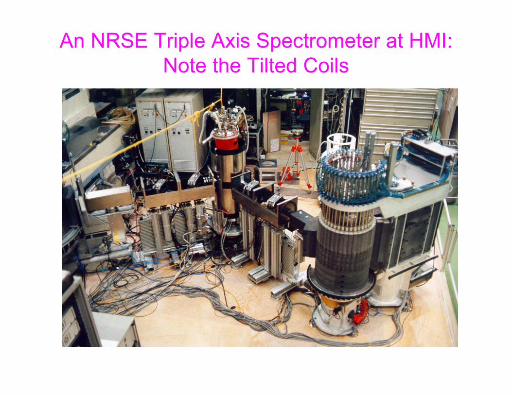
An NRSE Triple Axis Spectrometer at HMI:Note the Tilted Coils

Measuring Line Shapes for Inelastic Scattering
• Spin echo polarization is the FT of scattering within the spectrometertransmission function
• An echo is obtained when
• Normally the lines of constant spin-echo phase have no gradient in Q,ωspace because the phase dependsonly on
• The phase lines can be tilted by using“tilted” precession magnets
ω
Q
ω
Q
22
221
1
2
2
1
1
1 0)()(
kN
kN
kBd
kBd
dkd
=⇒=⎥⎦
⎤⎢⎣
⎡−
k
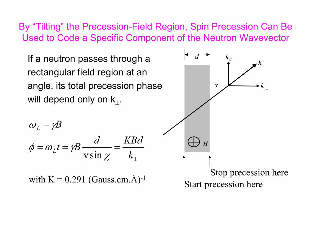
By “Tilting” the Precession-Field Region, Spin Precession Can Be Used to Code a Specific Component of the Neutron Wavevector
If a neutron passes through arectangular field region at anangle, its total precession phase will depend only on k⊥.
⊥k
d
χ
B
kk//
⊥
===
=
kKBddBt
B
L
L
χγωφ
γω
sinvStop precession here
Start precession herewith K = 0.291 (Gauss.cm.Å)-1

“Phonon Focusing”• For a single incident neutron wavevector, kI, neutrons are
scattered to kF by a phonon of frequency ωo and to kf by neighboring phonons lying on the “scattering surface”.– The topology of the scattering surface is related to that of the phonon dispersion
surface and it is locally flat
• Provided the edges of the NSE precession field region are parallel to the scattering surface, all neutrons with scatteringwavevectors on the scattering surface will have equal spin-echo phase
Q0
kIkF kf
scattering surface
Precession field region
kf⊥
“Tilted Fields”
• Phonon focusing using tilted fields is available at ILL and in Japan (JAERI)….however,
• The technique is more easily implemented using the NRSE method and is installed as an option on a 3-axis spectrometers at HMI and at Munich
• Tilted fields can also be used can also be used for elastic scattering and may be used in future to:– Increase the length scale accessible to SANS– Separate diffuse scattering from specular scattering in reflectometry– Measure in-plane order in thin films– Improve Q resolution for diffraction

An NRSE Triple Axis Spectrometer at HMI:Note the Tilted Coils
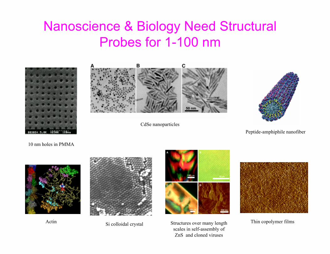
Nanoscience & Biology Need Structural Probes for 1-100 nm
10 nm holes in PMMA
CdSe nanoparticlesPeptide-amphiphile nanofiber
Actin
1μ
Si colloidal crystal
10μ2μ
Thin copolymer filmsStructures over many lengthscales in self-assembly of ZnS and cloned viruses
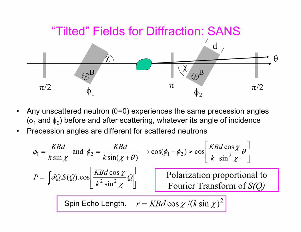
“Tilted” Fields for Diffraction: SANS
• Any unscattered neutron (θ=0) experiences the same precession angles (φ1 and φ2) before and after scattering, whatever its angle of incidence
• Precession angles are different for scattered neutrons
π/2 π/2π
⎥⎥⎦
⎤
⎢⎢⎣
⎡=
⎥⎥⎦
⎤
⎢⎢⎣
⎡≈−⇒
+==
∫ QkKBdQSdQP
kKBd
kKBd
kKBd
χχ
θχχφφ
θχφ
χφ
22
22121
sincoscos).(.
sincoscos)cos(
)sin( and
sin
χ θχ
B B
Polarization proportional toFourier Transform of S(Q)
φ1 φ2
d
Spin Echo Length, 2)sin/(cos χχ kKBdr =
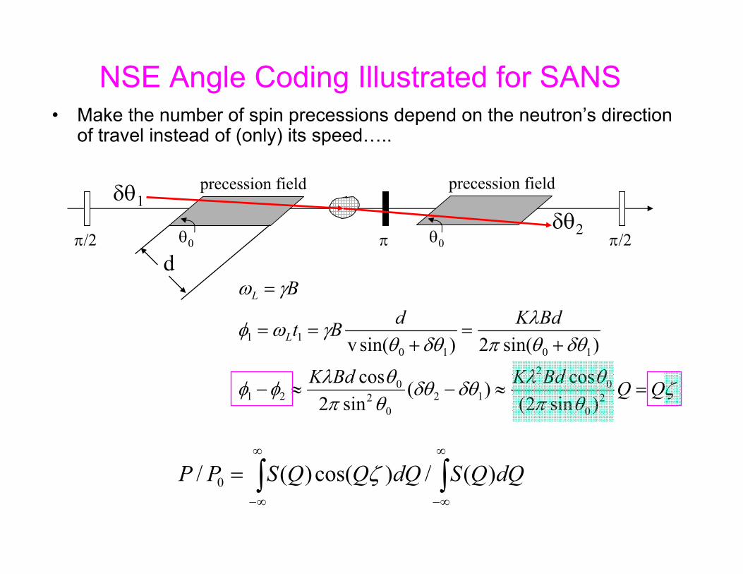
NSE Angle Coding Illustrated for SANS• Make the number of spin precessions depend on the neutron’s direction
of travel instead of (only) its speed…..
π/2 π/2π
precession field precession field
θ0 θ0
d
ζθπ
θλδθδθθπ
θλφφ
δθθπλ
δθθγωφ
γω
QQBdKBdK
BdKdBt
B
L
L
=≈−≈−
+=
+==
=
20
02
120
20
21
101011
)sin2(cos)(
sin2cos
)sin(2)sin(v
∫∫∞
∞−
∞
∞−
= dQQSdQQQSPP )(/)cos()(/ 0 ζ
δθ1δθ2

+BO -BO
spinanalyser
spinpolarizer
1st spin-echoarm
2nd spin-echoarm
DIFFERENT PATH LENGTHS FOR THE DIFFERENT TRAJECTORIES !
P =
1The Classical Picture of Spin Precession
sampleposition
Viewgraphsequence byA. Vorobiev
+BO -BO
spinanalyser
spinpolarizer
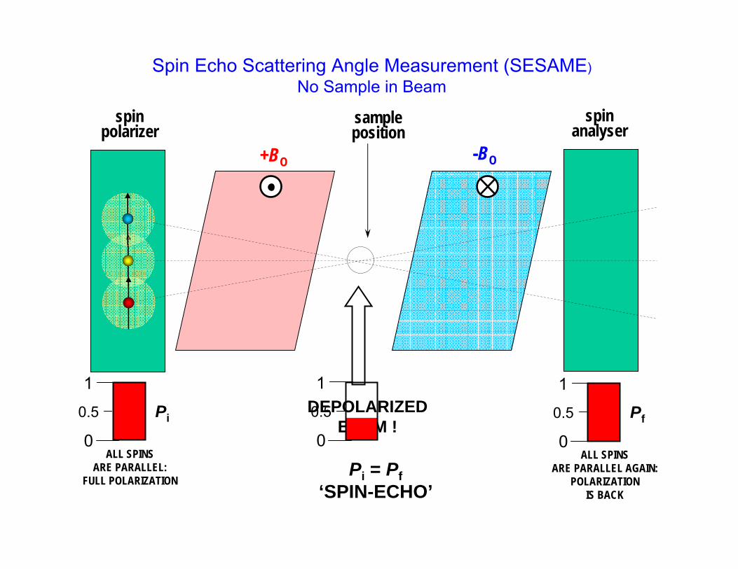
DEPOLARIZEDBEAM !
ALL SPINSARE PARALLEL:
FULL POLARIZATION
0
1
0.5 Pi
0
1
0.5
ALL SPINSARE PARALLEL AGAIN:
POLARIZATIONIS BACK
0
1
0.5 Pf
Spin Echo Scattering Angle Measurement (SESAME)No Sample in Beam
Pi = Pf‘SPIN-ECHO’
sampleposition
+BO -BO
spinanalyser
spinpolarizer
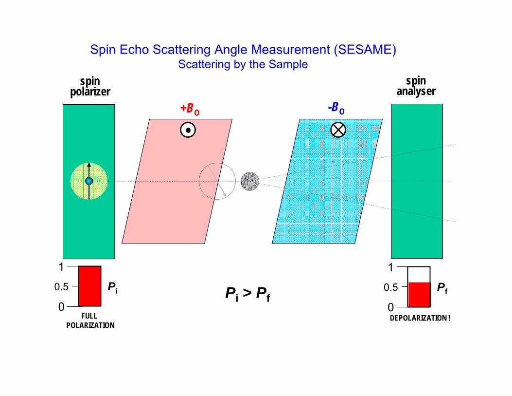
FULL POLARIZATION
0
1
0.5 Pi
DEPOLARIZATION !0
1
0.5 Pf
Spin Echo Scattering Angle Measurement (SESAME)Scattering by the Sample
Pi > Pf
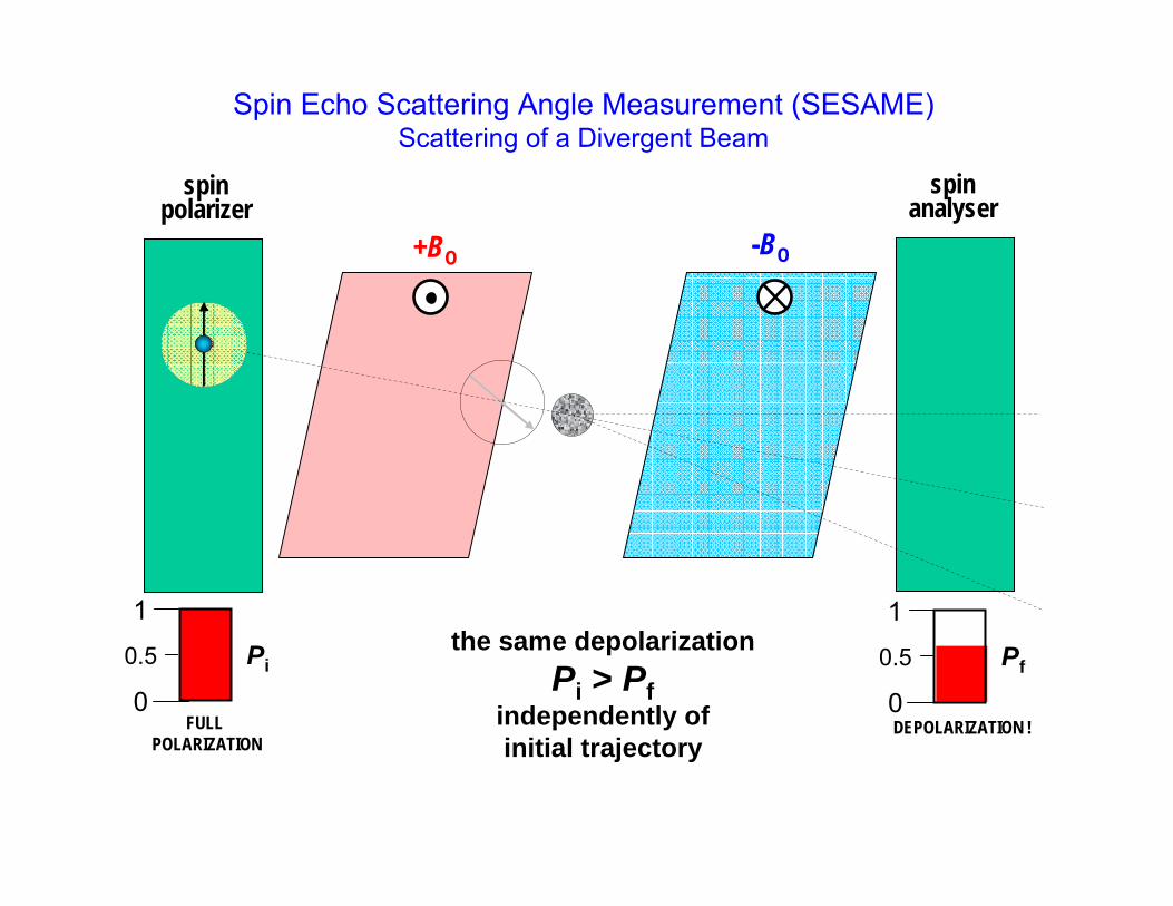
+BO -BO
spinanalyser
spinpolarizer
FULL POLARIZATION
0
1
0.5 Pi
DEPOLARIZATION !0
1
0.5 Pfthe same depolarization
Pi > Pfindependently ofinitial trajectory
Spin Echo Scattering Angle Measurement (SESAME)Scattering of a Divergent Beam
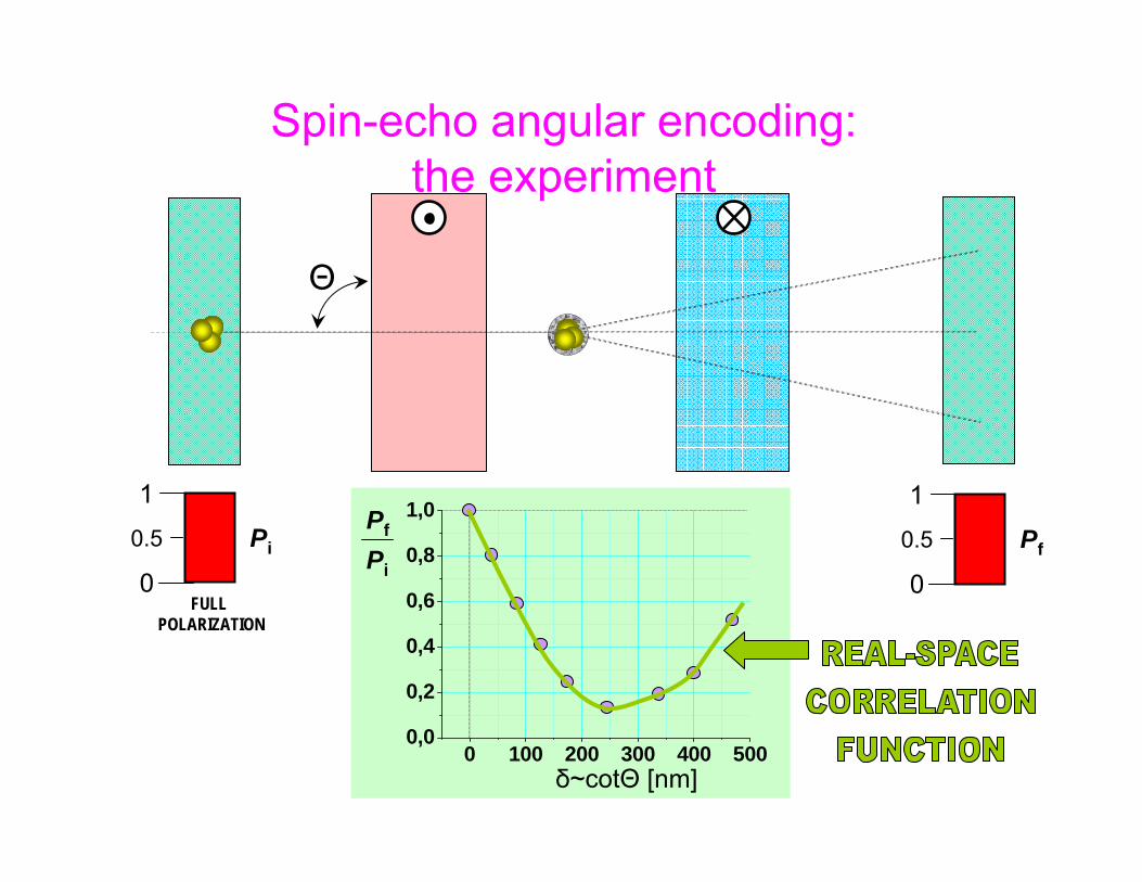
FULL POLARIZATION
0
1
0.5 Pi
0 100 200 300 400 5000,0
0,2
0,4
0,6
0,8
1,0
δ~cotΘ [nm]
Pf
Pi
Θ
0
1
0.5 Pf
Spin-echo angular encoding:the experiment

How Large is the Spin Echo Length for SANS?
7,5001065,000
3,5002065,000
1,5002045,000
1,0002043,000
r(Angstroms)
χ(degrees)
λ(Angstroms)
Bd/sinχ(Gauss.cm)
It is relatively straightforward to probe length scales of ~ 1 micron

HMI Experiments:2002 - 2004 1
1
2
3
4
5
2
1. π/22. Precession film3. Sample4. π5. Iron plate

High Angular Resolution using SESAME
1
2
31
4
5
21
2
31
4
5
2
0 50 100 150 2000.90
0.92
0.94
0.96
0.98
1.00
P/P
0
Spin Echo Length (nanometers)
240 250 260 270 280 290 300 310 320 330
0
500
1000
1500
2000
2500
off02 on02 offminuson
inte
nsity
channel
omega = 0.2 degrees
Thin, magnetized Ni0.8Fe0.2 films on silicon wafers (labelled 1, 2 & 4) are the principal physical components used for this new method.
High angular resolution is obtained using Neutron Spin Echo.
A 200 nm correlation distance was achieved for SANS
Specular neutron reflection (blue) was separated from diffuse reflection with high fidelity. Black and red data include diffuse scattering
Patterson function for PS spheres(measurement & theory)
240 250 260 270 280 290 300 310 320 330-200
0
200
400
600
800
Inte
nsity
PSD Channel
Diffuse Specular
theta = 0.4 degrees

Conclusion:NSE Provides a Way to Separate Resolution from
Monochromatization & Beam Divergence
• The method currently provides the best energy resolution for inelastic neutron scattering (~ neV)– Both classical NSE and NRSE achieve similar energy resolution– NRSE is more easily adapted to “phonon focusing” I.e. measuring the energy
line-widths of phonon excitations
• The method is likely to be used in future to improve (Q) resolution for elastic scattering– Extend size range for SANS (SESANS)– May allow 100 – 1000 x gain in measurement speed for some SANS exps– Separate specular and diffuse scattering in reflectometry– Measure in-plane ordering in thin films (SERGIS)
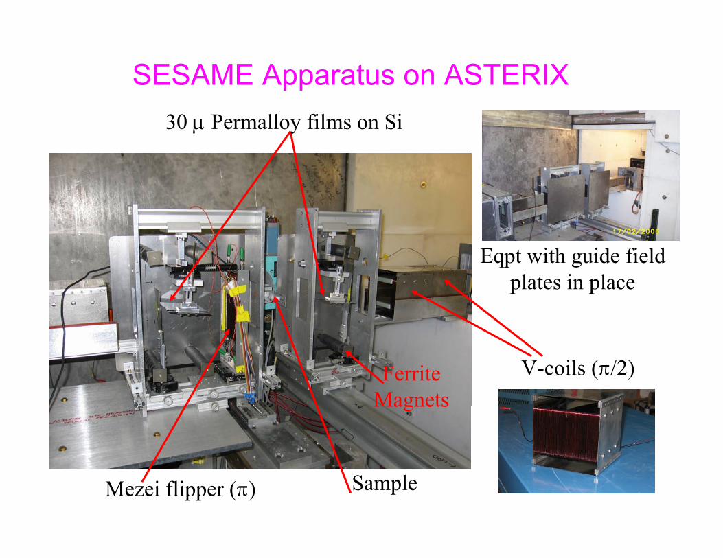
SESAME Apparatus on ASTERIX30 μ Permalloy films on Si
Mezei flipper (π)
V-coils (π/2)
Sample
Eqpt with guide fieldplates in place
FerriteMagnets
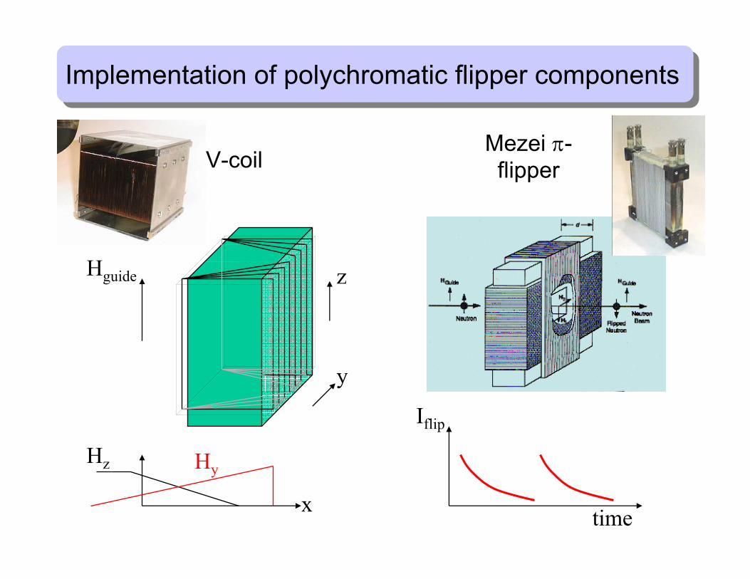
Hz
x
Hy
Iflip
time
Mezei π-flipper
y
z
V-coil
Hguide
Implementation of polychromatic flipper componentsImplementation of polychromatic flipper components

Obtaining a Spin Echo
Measure flip ratioas a function of flipper position
With π flipper set to echo position, incline 1st
Py film, then measure flip ratio as a function of 2nd film angle
4 5 6 7 8 9 10-5
-4.5
-4
-3.5
-3
-2.5
-2
-1.5
Calculated result allows SEL to be related to lamda
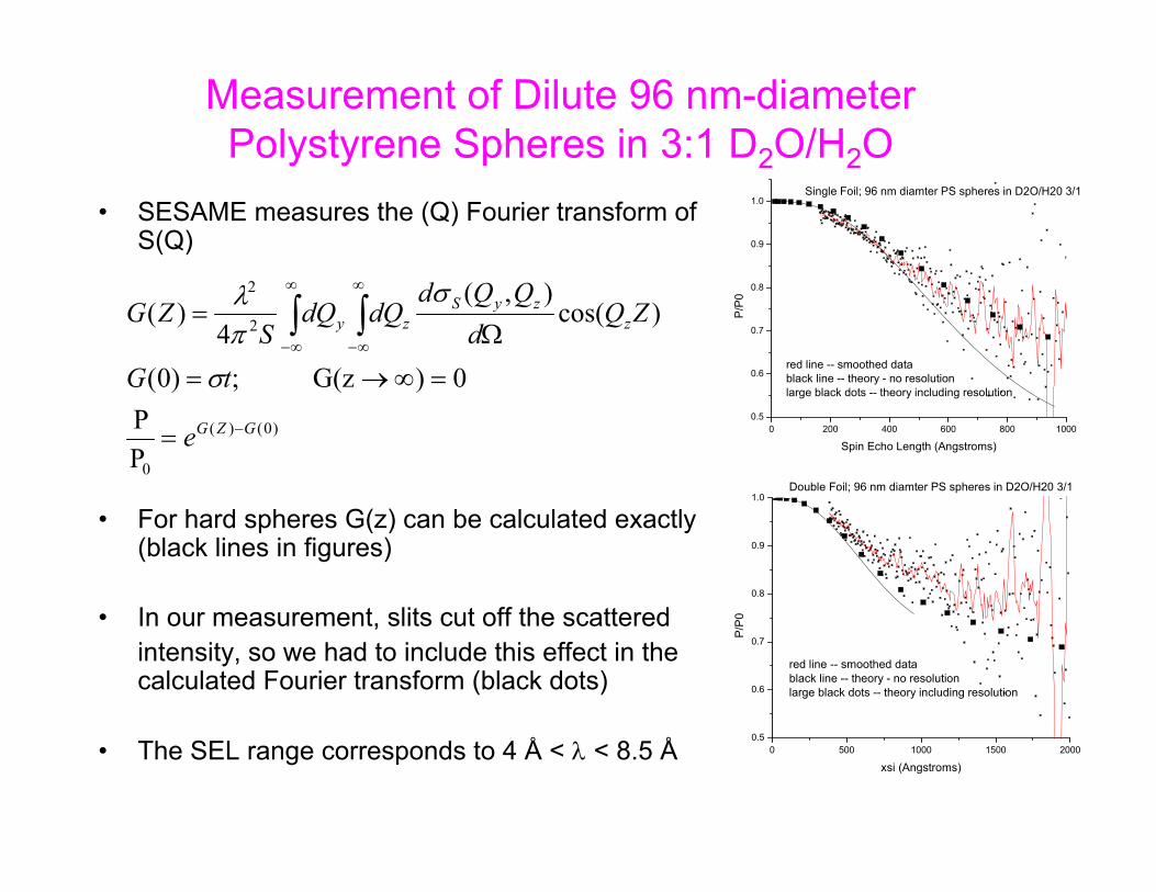
Measurement of Dilute 96 nm-diameter Polystyrene Spheres in 3:1 D2O/H2O
• SESAME measures the (Q) Fourier transform of S(Q)
• For hard spheres G(z) can be calculated exactly (black lines in figures)
• In our measurement, slits cut off the scattered intensity, so we had to include this effect in the calculated Fourier transform (black dots)
• The SEL range corresponds to 4 Å < λ < 8.5 Å
0 200 400 600 800 10000.5
0.6
0.7
0.8
0.9
1.0
red line -- smoothed datablack line -- theory - no resolutionlarge black dots -- theory including resolution
P/P
0
Spin Echo Length (Angstroms)
Single Foil; 96 nm diamter PS spheres in D2O/H20 3/1
)0()(
0
2
2
PP
0)G(z ;)0(
)cos(),(
4)(
GZG
zzyS
zy
e
tG
ZQd
QQddQdQ
SZG
−
∞
∞−
∞
∞−
=
=∞→=
Ω= ∫∫
σ
σπλ
0 500 1000 1500 20000.5
0.6
0.7
0.8
0.9
1.0
red line -- smoothed datablack line -- theory - no resolutionlarge black dots -- theory including resolution
P/P
0
xsi (Angstroms)
Double Foil; 96 nm diamter PS spheres in D2O/H20 3/1
Conclusions from Precession Film Experiments• SESAME can be implemented using thin magnetic films at
either CW or pulsed neutron sources– Particularly good for pulsed source because spin echo length is scanned by λ– Spin echo lengths up to ~ 250 nm are not hard to achieve using cold
neutrons– Precession fields are large (~ 1 T) so only thin films are needed– Precession field boundaries are well-defined
• The method has several limitations;– 30 μ – 100 μ Permalloy films are not readily available– Film thickness homogeneity is a limitation (5 - 10% by electro-deposition)– Small film inclinations are needed for large spin echo lengths => large films
for reasonable neutron beam size– Film transmission losses increase as spin echo length goes up

Glass Slab:n = n0; dn/dλ = - |d|
Glass Slabwith anomalous dispersion;
n = n0; dn/dλ = |d|
The spatial separation, z, of the red and blue rays depends on:(a) dn/dλ; (b) the glass thickness; (c) the inclination of the slab
z
An Optical Analogy

A Better Method?
• A better method is to use separated π flippers– Implemented at Delft using thin Py films as flippers– Implemented on EVA using NRSE
• NRSE is clumsy to pulsed sources– Try triangular cross section solenoids
+ - - + + - - +
π/2 π/2π200 mm
L = 200-500 mm
neutron
Stay tuned …..

Cutting the slab into prisms allows the spatial separation of red andblue rays to be controlled by the separation of the prisms
d
Adding prisms with the opposite dispersion increases the separation ofthe red and blue rays
Increasing the Spin Echo Length
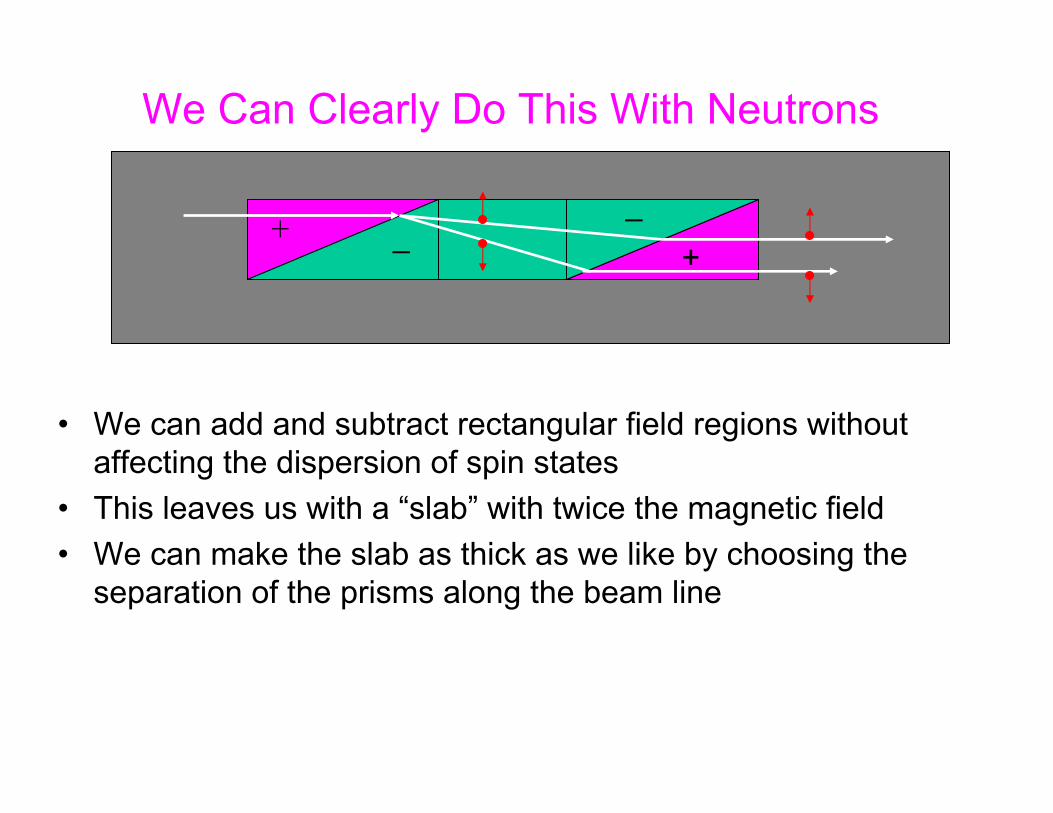
We Can Clearly Do This With Neutrons
• We can add and subtract rectangular field regions without affecting the dispersion of spin states
• This leaves us with a “slab” with twice the magnetic field• We can make the slab as thick as we like by choosing the
separation of the prisms along the beam line
++─
─

We Can Do the Same Thing With Neutrons
• Prepare neutrons in a mixture of eigenstates | > + | >• The two, correlated spin states of a neutron can be separated
in space by a magnetic field with inclined boundaries• When the states are recombined, they provide information
about correlations between scattering events that are separated by the spin echo length, z
+ vemagnetic field
─ vemagnetic field
z
sample

x
z
yαi
αf
ϕ
qx = (2π/λ)( cosαf - cosαi )qy = (2π/λ) sinϕ
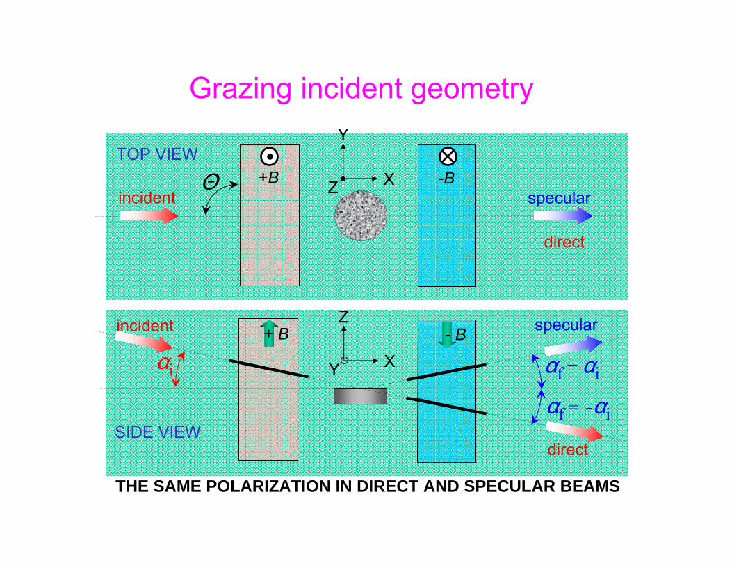
Geometry at grazing incidence
αf Resolve with PSD
ϕ Resolve with Spin Echo
tight collimation
coarse collimation
Θ
αi αf = αi
αf = -αi
TOP VIEW
SIDE VIEW
Y
XZ
Z
XY
+B -B
+ B - Bincident
incident specular
specular
direct
direct
THE SAME POLARIZATION IN DIRECT AND SPECULAR BEAMS
Grazing incident geometry

A comparative study of P. Müller-Buschbaum et al., Physica B283,53 (2000)
AFM picture of drops of d-polystyrene/polyparamethylstyreneon silicon
Zoomed AFM picture
Model of scattering length densities as seenby X-rays(GISAXS)
Model of scatteringlength densities asseen by neutrons
(GISANS)
Dewetting of polymer-blend films from Silicon

a) scattering geometry. The incident beam (I) impinges on the sample surface at a shallow angle αi; transmitted (T), specular (S) and diffuse (Y) intensities are simultaneously recorded by PSD.
b) Image taken by 2-dimensional PSD during real experiment. The size of the incoming beam at the sample position was 30×2 mm2.

Diffraction figure in transmission and reflection geometry
GISANS from copolymer dropletsD22(ILL), 8 hours
sinϑf + sinϑisinϑI + sinϑf cosϕ
qz
cosϑf sinϕsinϑf sinϕqy
cosϑf cosϕ - cosϑicosϑf - cosϑiqx
Transmission Reflection

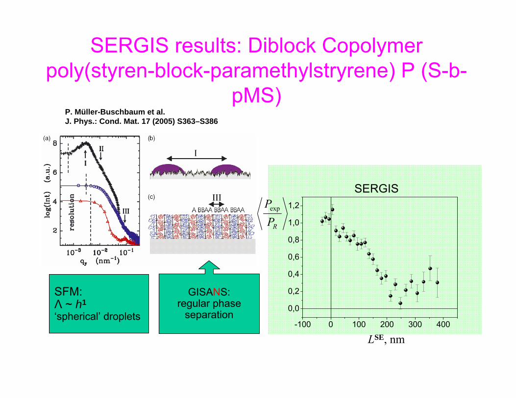
P. Müller-Buschbaum et al.J. Phys.: Cond. Mat. 17 (2005) S363–S386
SFM:Λ ~ h2
pancake-type droplets
0 100 200 300 4000,4
0,6
0,8
1,0
1,2
LSE, nm
GISANS:no internal regular phase separation
GIS
AXS
RPPexp
SERGIS
SERGIS results: PpMS(polyparamethylstryrene):dPS
BLEND 3:2
P. Müller-Buschbaum et al.J. Phys.: Cond. Mat. 17 (2005) S363–S386
SFM:Λ ~ h1
‘spherical’ droplets
LSE, nm
RPPexp
SERGIS
GISANS:regular phase
separation-100 0 100 200 300 400
0,0
0,2
0,4
0,6
0,8
1,0
1,2
SERGIS results: Diblock Copolymerpoly(styren-block-paramethylstryrene) P (S-b-
pMS)
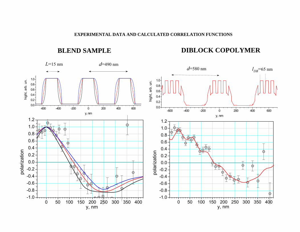
-600 -400 -200 0 200 400 6000.0
0.2
0.4
0.6
0.8
1.0
high
t, ar
b. u
n.
y, nm
0 50 100 150 200 250 300 350 400-1.0-0.8-0.6-0.4-0.20.00.20.40.60.81.01.2
pola
rizat
ion
y, nm
L=15 nm d=490 nm
EXPERIMENTAL DATA AND CALCULATED CORRELATION FUNCTIONS
BLEND SAMPLE DIBLOCK COPOLYMER
-600 -400 -200 0 200 400 6000.0
0.2
0.4
0.6
0.8
1.0
high
t, ar
b. u
n.
y, nm
lDB=65 nmd=580 nm
0 50 100 150 200 250 300 350 400-1.0-0.8-0.6-0.4-0.20.00.20.40.60.81.01.2
pola
rizat
ion
y, nm
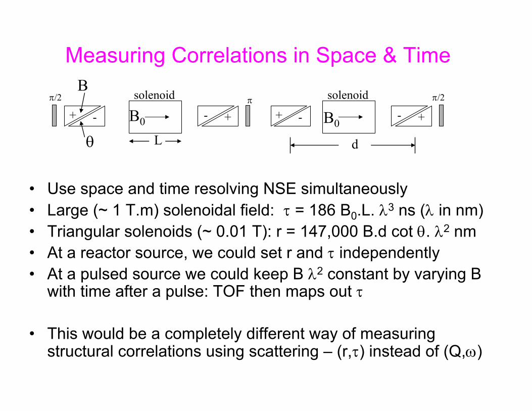
Measuring Correlations in Space & Time
• Use space and time resolving NSE simultaneously• Large (~ 1 T.m) solenoidal field: τ = 186 B0.L. λ3 ns (λ in nm)• Triangular solenoids (~ 0.01 T): r = 147,000 B.d cot θ. λ2 nm• At a reactor source, we could set r and τ independently• At a pulsed source we could keep B λ2 constant by varying B
with time after a pulse: TOF then maps out τ
• This would be a completely different way of measuring structural correlations using scattering – (r,τ) instead of (Q,ω)
-+ -+π/2 π/2π
+-+-
solenoid solenoid
dL
B0 B0
B
θ
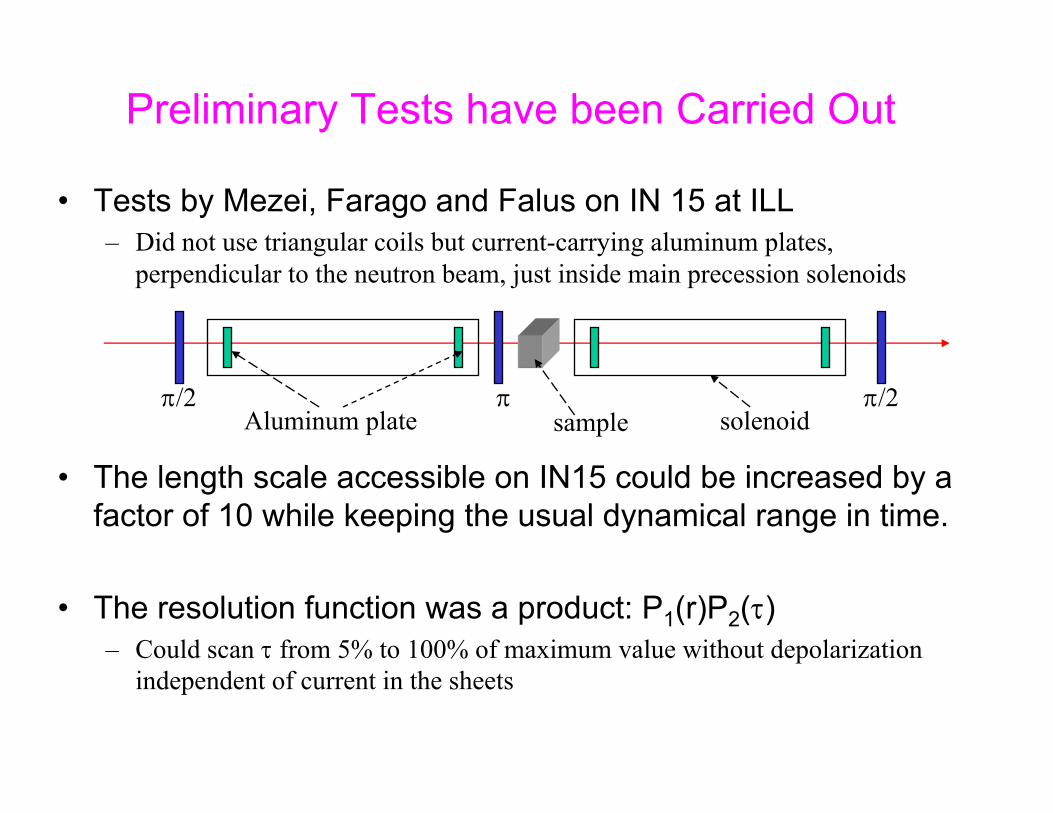
Preliminary Tests have been Carried Out
• Tests by Mezei, Farago and Falus on IN 15 at ILL– Did not use triangular coils but current-carrying aluminum plates,
perpendicular to the neutron beam, just inside main precession solenoids
• The length scale accessible on IN15 could be increased by a factor of 10 while keeping the usual dynamical range in time.
• The resolution function was a product: P1(r)P2(τ)– Could scan τ from 5% to 100% of maximum value without depolarization
independent of current in the sheets
solenoidπ/2 π π/2
Aluminum plate sample

Spin Echo Polarization versus r: P1(r)
• The relatively rapid decrease of P1(r) with r is not yet understood
0 10 20 30 400.0
0.2
0.4
0.6
0.8
1.0
250 500 750 1000
N
orm
aliz
ed N
SE s
igna
l P(r
)
Current in field tilt sheets [A]
Fourier distance r [Å]
Stay tuned…….
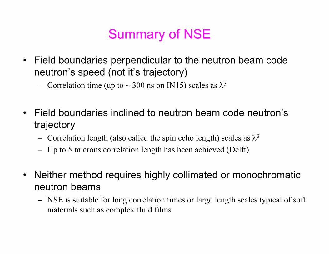
Summary of NSE
• Field boundaries perpendicular to the neutron beam code neutron’s speed (not it’s trajectory)– Correlation time (up to ~ 300 ns on IN15) scales as λ3
• Field boundaries inclined to neutron beam code neutron’s trajectory – Correlation length (also called the spin echo length) scales as λ2
– Up to 5 microns correlation length has been achieved (Delft)
• Neither method requires highly collimated or monochromatic neutron beams– NSE is suitable for long correlation times or large length scales typical of soft
materials such as complex fluid films

Collaborators
Experiments at HMI, BerlinMike Fitzsimmons, LANLHelmut Fritzsche, Chalk RiverMarita Gierlings, HMIJanos Major, MPI, Stuttgart
Experiments at LANSCEMike Fitzsimmons, LANLGian Felcher, ANL
Triangular solenoidsMike Fitzsimmons, LANLMark Leuschner, IndianaPaul Stonaha, IndianaAdam Washington, IndianaHaiyang Yan, IndianaHal Lee, SNS

![High Resolution Spectroscopy with the Neutron Resonance Spin … · 2017. 10. 26. · trometers. Neutron spin echo (NSE) introduced by Mezei [1, 2] is one of the outstanding methods](https://img.dokumen.tips/doc/110x75/610966ad54d2d953a71b3862/high-resolution-spectroscopy-with-the-neutron-resonance-spin-2017-10-26-trometers.jpg)


![by Roger Pynn - Indiana University · 2006-11-27 · 60 80 100 120 140 160-10 0 10 203040 Static field, H s (z) [Oe] Distance along neutron path [cm] RF field region 15 cm ∇H =](https://img.dokumen.tips/doc/110x75/5f98fbec9e2b5815e22b3df0/by-roger-pynn-indiana-university-2006-11-27-60-80-100-120-140-160-10-0-10-203040.jpg)


![arXiv:0803.4170v1 [physics.ins-det] 28 Mar 2008 · neutron spin echo techniques, a large fraction of slow neutron scattering spec-trometers of interest for neutron spectroscopy can](https://img.dokumen.tips/doc/110x75/6001651b431a684e12181272/arxiv08034170v1-28-mar-2008-neutron-spin-echo-techniques-a-large-fraction.jpg)