Embed Size (px)
Citation preview


J
I
This research has been supported by the Defense AdvancedResearch Projects Agency under Contract N00039-77-C-0398,ARPA Order No. 3i75 (Amendment 1), and monitored by theNaval Electronic Systems Command (Program Code 9D30).
The views and conclusions contained in this paper arethose of the authors and should not be interpreted asnecessarily representing the official policies, eitherexpressed or implied, of the Defense Advanced ResearchProjects Agency or the U.S. Government.
.................................. . .... I
-J


UNCLASSIFIEDSCUmvv CLAMaPICATION OF TNIS PA4fE41I DMt , af,
Item 20. (Continued)ha highly automated agent through which tointeractively direct and modify the generation of displays whoscontent cuts across sub-system boundaries. The key to providinthis high level of automation lies in the correct representa-tion of knowledge about graphics, the display device, theapplication domain, and the user's needs.
An experimental AIPS has been constructed utilizing a high-level knowledge representation language (KLONE) implemented aspart of this effort., This system manipulates general descrip-tions of informatiori presentation concepts such as domainobjects, coordinate systems, transformations, display regions,display objects, and the relationships between domain objectsand their depictions. This paper introduces the InformationPresentation System concept, describes the KLONE knowledgelanguage and details the current state of the experimental
.11
I
UNCLASSIFIEn
SUtCURI?? QLASSIFICA1'ION Of rNIS PAGCCWMRi Date Zater*4

Report No. 3849 Bolt Beranek and Newman Inc.
TABLE OF CONTENTS
~Page
1. INTRODUCTION 1
* i1.1 Premt-,s of the Research 11.2 Resources 31.3 Methodology 61.4 Current Status of the Research 8
2. THE USER INTERFACE PROBLEM 13
3. PRESENTATION SYSTEM ARCHITECTURE 15
3.1 World Model 153.2 User Model 173.3 Presentation Model 183.4 Viewing Organization Model 193.5 Realization Model 19
4. BIT-MAP GRAPHICS 21
4.1 Concept 214.2 Current Hardware 224.3 Functional Characteristics 24
I
5. KNOWLEDGE REPRESENTATION LANGUAGE 27
5.1 Theoretical Basis 275.2 Primary Contributions of KLONE 335.3 Internal Generic Concept Structure 35

Bolt Beranek and Newman Inc. Report No. 3849
5.4 Aspects of Structured Inheritance 415.5 Individuals and Individuation 485.6 Metadescriptions and IHooks 495.7 Implementation 51
6. PRESENTATION SYSTEM CONCEPTS 55
6.1 Presentation Model 556.2 The Viewing Organization Model 576.3 Realization Model 656.4 Procedural Knowledge 686.5 An Example Presentation 70
7. THE MIDDLE EARTH DEMONSTRATION SYSTEM 81
8. CONCLUSION 85
APPENDIX A. AIPS KLONE NETWORK 93
APPENDIX B. BIT MAP GRAPHICS FUNCTIONS 117
iii

Report No. 3849 Bolt Beranek and Newman Inc.
LIST OF FIGURES
FIGURE 1: AIPS KNOWLEDGE BASE STRUCTURE ... ........... 16
FIGURE 2: Example of an GENERIC ROLE STRUCTURE .. ........ 37
FIGURE 3: Example of a PARAMETERIZED INDIVIDUAL CONCEPT. . . 39
FIGURE 4A/B: Examples of STRUCTURED INHERITANCE .......... .42
FIGURE 5: Example of an INSTANCE ROLE ... ............ 45
FIGURE 6: Examples of ROLE DIFFERENTIATION ... .......... 46
FIGURE 7: PRESENTATION MODEL ...... ................. 56
FIGURE 8: VIEWING ORGANIZATION MODEL .... ............. 58
FIGURE 9A: INJECTION/PROJECTION KLONE STRUCTURE .......... .61
9B: INJECTION/PROJECTION SCHEMA .... ............ 62
FIGURE 10: REALIZATION MODEL ....... ................ 66
FIGURE 11: FORMATION MAP PRESENTATION ..... ............. 71
FIGURE 12: TRACK PRESENTATION ...... ................. 73
FIGURE 13: GRID PRESENTATION ...... ................. 75
FIGURE 14: NTDS DISPLAYFORM COMPOSITES .... ............ 76
FIGURE 15: INSTANCE OF FORMATION ..... ............... 78
FIGURE 16: OVER-THE-HORIZON (OTH) DISPLAY ... .......... . 81
iii

Report No. 3849 Bolt Beranek and Newman Inc.
1. INTRODUCTION
1.1 Premises of the Research
We believe that -he problem with current command and control(C2) systems is the general view of what those systems ought tobe, and not any particular equipment or algorithms utilized in
them. It is the nature of C2 systems that we must comprehend
more fully, and in a manner suited to providing guidance for
system design. Real-time symbolic processing technology can
provide a comprehensive new paradigm for C2 systems, and thenecessary hardware, software, and conceptual resources have
developed to the point where it is possible to meaningfullyexplore the implications. This paradigm and its supporting
technology offer the potential for solving many of the problems
that have been intractable heretofore in the military's searchfor operationally useful and usable command and control systems.
Currently, there are two prevalent paradigms for C2 systems.
The first is that a C2 system is a communications system. That
is, its purpose is to facilitate communications between the
commanders who must make the decisions. Taken to its extreme,the position is that since direct voice communications between
people is one of the most efficient means we have today, a C2
system that is an advanced telephone network (reliable, secure,
etc.) would "solve the command and control problem". A more-J
sophisticated interpretation is that the data and models stored
in a C2 system are themselves a communications mechanism between
people, and that the communications function incorporates much
more than simple person-to-person voice links.
The second common paradigm of a C2 system defines it as adata repository. From this view, the completeness, relevance,
• 1

Bolt Beranek and Newman Inc. Report No. 3849
accuracy, reliability and accessibility of data are the primaryissues. The crucial problem with the data paradigm is that data
per se is not information; often the more massive the data, the
less the information that can be derived from it. The data
involved is invariably low-level and as detailed as current
technology and economics will allow. But the items of greatest
interest to the commander are situations, threats, plans, goals,
and constraints -- conceptual objects of a much higher level. In
a C2 system built under the data paradigm, these higher-levelconceptual objects are stored, if at all, as text strings,
essentially uninterpretable by the system itself. As a result,
the system can provide little active assistance to the decision
maker.
Our paradigm is that a C2 system is a coordinated collectionof symbolic processing subsystems that facilitate the command and
control task: the synthesis of information from massive
collections of data. The system components naturally include
communications among people and machines, as well as data storage
and access. But the data produced by these functions must be
interpreted to produce a situation assessment, further
interpreted to judge the validity and sensitivity of the
hypothesis space that produced the assessment, and interpreted
again to generate appropriate plans. Models, hypotheses and
plans are all symbolic entities that can be manipulated by a
properly designed computer-based decision aiding system.
There are several technological trends that are providing uswith the leverage to exploit a symbolic processing paradigm for
command and control. Chief among them is the maturation of our
understanding of fundamental knowledge representation issues. As
important, however, is the advent of real-time symbolic processor
hardware and the large library of available software being
produced in support of real-time symbolic processing, as well as
2

Report No. 3849 Bolt Beranek and Newman Inc.
the emergence of a new systems development methodology that
exploits sophisticated programming tools. It is the focusing of
these forces on C2 problems that is creating the exciting
r possibility of a fundamental advance.
.
1.2 Resources
First generation real-time symbolic processors are
microprogrammed versions of the machine technology available
today. These machines emulate a virtual machine not too unlike
current computers in design (as a community we are not at all
agreed on any optimum design goals). However, the efficienciesaccruing from optimizing the virtual machine to suit the
programming language (usually LISP), combine with advances in
circuit design and construction (such as VLSI) to result in an
important improvement in the cost-performance trade-off for
symbolic processing.
New technology is always something of a surprise, even with
forecasts, analogues and simulations. The bigger the change the
less able we are to predict the consequences. One rule of thumb
used in the computing community is that a difference of one order
of magnitude is not too difficult to assimilate, while a
difference of two orders of magnitude is revolutionary. In very
rough terms, the current set of prototype real-time symbolic
processors run LISP about three to five times faster than it runs
on currently available timesharing machines (e.g. PDP-10KA) and
do so perhaps ten times more cheaply. Though the comparison is
clearly not this simple, this combination puts us near the
boundary of drastic conceptual change.
Just as important as computational speed and cost are twoother features accompanying improved performance. First, the new
3

Bolt Beranek and Newman Inc. Report No. 3849
symbolic processors tend to be physically similar in scale to the
* "micro-computers" of the early seventies. That is, in physical
size (a surprisingly important C2 parameter) they are likely to
be a rack or less of equipment, and they will grow smaller with
time. Second, these machines have very large virtual memory
address spaces: 64 million bytes or more. These two features
allow the new possibility of installing very complex programs in
space-limited command centers.
*% 4 There is another hardware aspect of the emergent symbolic
processor systems that is very important for C2 applications:
integral bit-map graphic display. Our experience indicates that
a prerequisite to major advances in user-oriented systems is a
flexible graphic display capability that has been carefully
designed into the total system from the beginning. Bit-map
graphics technology allows flicker-free display of complex
figures. Most important is that the resolution of these displays
is high, with current systems aiming at 1024*1024 pixels.
Studies have shown that this resolution is good enough for
situation display, while lower resolution displays are marginal.
- A second important hardware feature is a local packet
network interface. There are now inexpensive local
packet-switched network implementations that have bandwidths
between three and eight megabits per second, and higher-bandwidth
networks are possible. These are being incorporated into the
prototype symbolic processors so that they can communicate with
centralized data and device resources, with other communications
networks, and with each other. This kind of capability is a
necessity when pursuing C2 applications.
To summarize, typical first generation symbolic processor
hardware includes a fast, large address space virtual-memory
computer directly executing a high-level language, an extremely
4

Report No. 3849 Bolt Beranek and Newman Inc.
flexible display capability, and a high-bandwidth local
communications link. An important goal of this research project
has been to anticipate and explore the specific implications of
this new resource for command and control.
The principle software resource on which this effort has
relied is Interlisp [Teitelman 781. A dialect of LISP, it
affords all of the many desirable characteristics of that
language: easy manipulability of programs, good facilities for
handling complex structured data, control structures far more
* powerful than can be found in almost any other high-level
language, and a large library of support functions. More than
just a programming language, Interlisp is a carefully constructed
programming environment. For example, it includes a program
editor that "knows" about the structural properties of the
language; a program source file updating system that keeps track
of editing changes; debugging aids that allow selective tracing
and breaking; a data record accessing package that facilitates
data-independent programming; functions to aid optimization by
selectively accumulating usage and timing statistics; and even a
code analyzing and question-answering system for exploring and
monitoring the access and control structure of large programs.
Finally, the user interface to this environment has been
augmented with a variety of aids such as automatic spelling
correction, simple program error correction, and a code
translator that supports a user-definable set of higher level
programming constructs. The net effect is an amplification in
programmer efficiency (for accomplished programmers) that enables
a small team to achieve what would otherwise take a larger group
a longer time to do.
Finally, since LISP is the language of choice for most ofthe Al community, there is a growing collection of potentially
usable tools that can be built into larger systems. These tools
5

Bolt Beranek and Newman Inc. Report No. 3849
are all expressions of some aspect of the symbolic processing
paradigm, and are the emergent results of the basic research into
knowledge representation, reasoning mechanisms, and natural
language understanding now being carried out in information
science laboratories. Examples include semantic network memory
systems; ATN parsers, grammars and grammar compilers for natural
language handling; production-rule based reasoning and
explanation systems; and interesting experimental systems for
user interaction and knowledge extraction.
1.3 Methodology
The well-publicized failure of large-scale C2 systems tomeet their goals, along with the failure of many large-scale
non-C2 software systems, has led to the conclusion that there is
something wrong at a basic level in the process of system
development. The business community is now exploring a
methodology that can best be described as "requirements
definition first", but this methodology has been carefully
applied in the C2 area for a long time with few discernible
results. The problem is that domains such as command and controlgive rise to requirements that are generally ill-defined,
changing, and closely interrelated to the evolving operational
goals and developing state of technology.
Symbolic processing systems rely on deep models of the
domain in which they work, with the most capable systems usingvery intricate, "realistic" representations. An example of such
a model is that when interpreting sensor returns, what is
considered normal behavior for an oil tanker may help resolve the :referent of a satellite radar report. These models, in the C2
domain, require more and different information than is currently
contained in any data base available, or found in studies of C2
6

Report No. 3849 Bolt Beranek and Newman Inc.
information processing requirements. The only way that has been
found thus far to successfully incorporate such knowledge into
computer systems is to have some "expert" or experts in the
domain involved in the process of creating the system. He or she
guides the setting of goals and priorities and criticizes the
developing system. A major flaw of the structured design
approach in the C2 context is that the delay between the
discussion of requirements and the first appearance of a system
tends to be longer than the duty cycle of the "expert". When the
* system appears, it is usually delivered to a different customer
with different problems.
We believe that it is becoming possible to use an entirely
new systems development methodology that will alleviate these
problems of focus and currency of delivered systems. This method
is to rapidly build successive generations of systems, each being
an incremental improvement on the previous one, at low cost and
with close feedback from the intended user community [Sandewall
78] . The important aspects of this approach are the joint
education of user and developer, the sequence of inexpensive
approximations to find out what is important, critical, or
desirable and the gradual collection of fairly small modules into
a comprehensive system.
It should now be clear why the advent of real-time symbolic
processors is so important. Previously, only two distinct paths
existed in styles of system building. One was to utilize the
full software and conceptual environment provided by symbolic
processing and LISP to arrive at timely experimental software
that tended to be too slow to evaluate reasonably. The other
route was careful system definition, a long process of system
building, and a usable resulting system that was obsolete before
it was delivered. Real-time symbolic processors enable both
7

Bolt Beranek and Newman Inc. Report No. 3849
rapid incremental systems design and implementation that
culminates in systems of sufficient power and speed for realistic
evaluation.
1.4 Current Status of the Research
The course we have pursued with this research has been to
utilize the incremental systems development methodology, aprlying
appropriate resources, to meaningfully articulate the symbolicprocessing paradigm for command and control. This articulation
requires much more than a report expressing notions that may beuseful. There are no direct means for exploring and evaluating a
paradigm per se. Instead we are using the indirect method of
* building experimental systems that inherently express the
* paradigm and then carefully searching for more general
implications of both the experimental systems and the paradigm
that produced them. Our original plan was to simultaneously
pursue a number of interesting symbolic processing applications
for command and control with several small experiments. At a
much later point, a major attempt was to be made on some
important C2 problem. As an initial experiment, we used a
version of the RITA production rule system [Anderson 77]
(written by R. Bobrow, in Inter lisp) to run a tactical threat
recognition and assessment aid (TECA) being developed
cooperatively by the Naval Ocean Systems Center and the RAND
Corporation [Brandenberg 77]. However, during the first quarter
of the project we concluded we should not dilute our efforts on
many small experiments, but settle instead on a focus of activitymatched to our current awareness of the capabilities of symbolic
processors and the needs of command and control. This decision
was partly due to the continuing delays in the availability of
symbolic processors outside of the developer's lab. Indeed, at
the time of this writing, such systems are still not available.
118|
.. . . . . ... . . . . . .. . . . . .. .. . i . .. .. il " - . . . . . . ,, .. . . . .

Report No. 3849 Bolt Beranek and Newman Inc.
The Massachusetts Institute of Technology Artificial Intelligence
Laboratory's LISP machine, the most likely choice as a vehicle
for this effort, did not become available this year as expected.
During the course of this work, Bolt Beranek and Newman
completed an effort to microcode a modified PDP-11/40 to support
Interlisp (Hartley 791 . This afforded us the opportunity to
demonstrate the concept of real time symbolic processing in a
stand alone environment; but since this system is limited in some
respects (e.g. no floating point hardware or garbage collector),
it is not a development resource.
In consultation with ARPA/IPTO program management we decided
on a single effort to build what we have termed AIPS, for
"Advanced Information Presentation System". This is a front-end
system intended to be an intelligent display manager. It
capitalizes on LISP machine architecture that provides a tightly
coupled bit-map raster scan display terminal. It also satisfies
a major need of command and control systems for a coordinated,
application-independent information presentation mechanism.
Finally, development of AIPS is strategic to demonstrating the"collection of symbolic processing systems" paradigm for C2,since it is the central element holding that collection together.
Representation of knowledge is the key to this kind of
system. In fact, representation of knowledge in a declarative
symbolic form is the only means we know by which such a systemt, -J
can be built. Accordingly, we have implemented a knowledgerepresentation language called KLONE that is a structured
inheritance network (SI-Net) system (Brachman 78a]. The general
approach has been derived from research conducted at Bolt Beranek
and Newman, Harvard, M.I.T., and the Xerox Palo Alto Research
Center [Woods 75, Brachman 77a, Roberts 77, Bobrow 76]. SI-Nets
are built out of conceptual nodes with rich internal structures,
9

Bolt Beranek and Newman Inc. Report No. 3849
using a carefully factored set of primitive relations. The
relationship between two concepts can have considerable fine
structure. This provides the necessary power to express how a
concept can inherit the characteristics of other concepts.
Knowledge representation technology has evolved rapidly over
the past few years and the KLONE system, which is
epistemologically based, fully reflects the current state of the
art. We have written a user reference manual for it [Brachman
78a] and there are several papers that describe the theoretical
* underpinnings of the system [Brachman 78b, Brachman 79]. It is
implemented in Interlisp, and the KLONE system itself is evolving
* 'in response to our experiences.
We have developed an initial set of concepts for interactive
presentation. This SI-Net can be found in Appendix A. While the
presentation concepts are still evolving, the current set
embraces view surfaces and projections of view surfaces, windows,
clipping, and injections from world coordinate systems onto view
surfaces. It also includes display forms such as circles, lines,
and points as well as composite display forms such as pentagon,
regular polygon and so on. The definitions for these include an
initial set of manipulation routines. Each display form has
attached procedures that know how to draw it, how to erase it,
and how to find the distance from that display form to a given
point.
The AIPS concept network described above has been embedded
in an interactive graphics environment that offers a multiple
window facility, albeit a rudimentary one. Currently, graphic
output is via a bit-map, raster-scan display with a PDP-11
serving as the graphics processor. Graphic input is provided via
a tablet and functions to discriminate the closest display form
of a given type to the designated position. This allows for
10

Report No. 3849 Bolt Beranek and Newman Inc.
goal-oriented interpretation of graphic input.
In order to drive the development effort, we have
implemented two experimental applications of the AIPS concept:
presentation of the status of the ARPANet and presentation of a
I simple, Over the Horizon (OTH) targeting situation. For the
first application, LISP procedures were written that take
information available from the Network Control Center at BBN and
various sources of TENEX performance statistics. We then
attached these to a KLONE description of an ARPANet display. The
full logical structure of the ARPANet complete with IMPS, TIPS,
hosts, and communications lines was represented in the network.
The example, while not military in nature, did exploit a dynamic
information source that is readily available and understandable.
The second AIPS application we constructed was a simple
tactical situation display. For this example we built up
concepts to describe the display of ships, missiles, aircraft,
projected positions, missile paths, and "bends" in missile flight
paths. In building this application, we experimented with the
use of "icons" or small pictures to depict domain objects, and
with graphic input menu selection. A major area of concern was
how to represent the interdependencies among display forms so
that changes in a form's position resulted in the correct
behavior by its associates.
Finally, the above demonstration system was transported onto
the PDP-11 Interlisp system, a prototype symbolic processor. To
accommodate the displaced graphics routines, we re-implemented
them in LISP so that the bit-map terminal would remain the
primary input/output of the system. The Interlisp-ll is not
quite complete, and the program still runs into troubles both
hardware and software in nature.
11

Bolt Beranek and Newman Inc. Report No. 3849
We are now in a position to consolidate this year's work
into a cleaner design, one that will better support a major
expansion of the conceptual system. We are about to explore a
higher level of presentation concepts such as desk top, chart,graph and table. One area that needs work in the near term is
that of describing a presentation's reaction to changes in the
environment. This includes devising presentations for doing
alerting. Of immediate importance in this regard is to interface
to a set of C2 knowledge sources that will provide a dynamic
environment for AIPS. The continuation of this effort, however,
has been moved to a new contract, and so this final report is
merely an introduction to the next phase of an applied research
* effort.
12

Report No. 3849 Bolt Beranek and Newman Inc.
2. THE USER INTERFACE PROBLEM
Current command and control systems, as well as all
commercially available computerized MIS systems, include"application" programs: programs that generate some particular
datum or decision aid. Each of these has its own input language
(usually a simple command structure) and its own display
4 management system. The input side has been heavily researched
with concepts such as natural language, "programming by example",
* hierarchical menus, and others. On the output side, however,
little has been done to separate the presentation of information
from the generation of that information. That is, each
application program displays information in the manner its
particular designer thought appropriate, and in general the
applications programmers control what the user sees.
This system design has two major limitations. The first is
that the design is rigid. The output behaviors of the component
systems are typically derived by studying some individual
decision maker to see what he or she would like to ask and then
programming in that set of queries. This is only a slight
caricature; for example, the Tactical Flag Command Center (TFCC)
system that the Navy is now developing can present some 200
different displays of information to the user; those 200 displays
are spelled out exactly as to what they will contain. However,
and especially in crisis situations, command and control users
need to combine information from diverse sources and view the
result from perspectives that are often unique to the situation
at hand. These presentations will not have been anticipated, and
the distribution of the display function throughout the C2 system
obstructs their generation.
The second effect of each application program doing its own
display management is that it is expensive. The input/output
13

Bolt Beranek and Newman Inc. Report No. 3849
portion of a program is invariably a major fraction of the code.
It may take up to half the programming effort and perhaps even
more of the design effort of a large and complex system. The
Department of Defense spends a great deal on software development
and that cost is increasing. Reduplication of a common and
costly function is one of the reasons.
The solution of these problems lies in the view that the
presentation of information is an understandable system functionin itself, separable from other functions. AIPS, the focus of
our current efforts, is intended to be a display management
system general enough to act as the front-end for all the
application programs in a command and control environment: Its
purpose is to present information to the C2 system users,
removing that job from the programs generating the information to
be displayed. This centralization of display responsibilities
provides a focus for efforts towards greater presentation
flexibility, reduces the task of writing a C2 application, and
consolidates the command structure for information display.
This concept fits very well into the current capabilities of
symbolic processing technology. Knowledge-based systems are
approaching a state of maturity that enables application to
realistic problems. Knowledge representation semantics and
inferencing mechanisms are becoming increasingly well understood.
Limited universe-of-discourse natural language systems are being
demonstrated often. All of these areas are involved in the
realization of AIPS. The emerging generation of symbolic
processors closely couple bit-map, raster scan graphics to a
powerful programming language. Thus, the resources for
intelligent display management are approaching the requirements,
with good chances for successful application to an important C2
need.
14

Report No. 3849 Bolt Beranek and Newman Inc.
3. PRESENTATION SYSTEM ARCHITECTURE
The purpose of this section is to provide a framework formore detailed treatment of AIPS' development. It is an overview
of the internal structure of AIPS as it is expected to be when
mature; it does not describe AIPS' current extent. Since AIPS is
a knowledge-based system, this description concerns the different
categories of knowledge important to AIPS, their interactions,and their functions. These collections of knowledge generally
are not modular or isolable. The interactions among them are too
dense, and the connections among them too rich for any of them to
be fully understood independently. Rather, this factorization is
an organizational ideal of the system's designers. Figure 1
below presents the architecture of a mature AIPS.
3.1 World Model
The first category of knowledge we have termed the worldmodel. It is a collection of descriptions of the world that isto be depicted. These descriptions purely concern the domain of
interest; they do not refer to what will be displayed, or how.Mainly, the knowledge at this level is represented declaratively.
It includes not only concrete entities of the domain world, such
as specific vehicles or geographic locations, but also genericand conceptual entities such as "rhumb line" and "order of
battle".
The world model is continually refreshed by informationsources external to the presentation system. These may include
both sources of nearly raw data and sophisticated decision aids.
The procedurally expressed knowledge at this level concerns how
LA 15

Bolt Beranek and Newman Inc. Report No. 3849
INFORMATION FROMEXTERNAL SOURCES USER INTERACTIONS
WORLD USERMODEL MODEL
SDOMAIN CONTENT
KNOWLEDGE SPECIFICATIONS
~PRESENTATION
DRAWING PICTURE
CONSTRAINT SPECI FICATIONSNEGOTIATIONS
MODEL
SDR A W I N G
SECIFICATION
DEVICEREALIZATIONCONSTRAINTMOENEGOTIATIONS
DISPLAYS
Figure 1.
16

Report No. 3849 Bolt Beranek and Newman Inc.
to translate communications with these sources into changes in
the world model descriptions. In some sense, this processing
converts data and information into knowledge by establishing
connections with appropriate conceptual models. Another view of
the world model is that it provides an interface to an indefinite
number of widely varying information sources. Its declarative
nature ideally suits that task because it facilitates control
over the interactions among these sources. Redundant or
conflicting information can be separately represented and
reconciled explicitly.
3.2 User Model
The user model is the category of information about the
system's end user. To begin with, this includes how the user's
preferences differ from AIPS' default assumptions. Some examples
are the user's desire that certain character fonts be used for
various purposes, his dislike of a particular method for doing
highlighting, his favorite formatting heuristics, and personal
variations or extensions of standard symbolog ies. Such
information can range widely in function within AIPS, so this
part of the user model is really distributed among AIPS' other
knowledge categories.
The user model proper consists of descriptions of the user
and his task. Descriptions of the user as an individual might
include items such as his reading speed, or his organizational
connections within the C2 team. However, since our eventual goal
is to arrive at a presentation system that works substantially
without explicit direction, AIPS most important knowledge of the
user concerns his perceptual and decision tasks. These task
models relate how the useros display requirements depend on the
current state of the world model. For example, the fact that the
17

Bolt Beranek and Newman Inc. Report No. 3849
weather is bad enough to be a decision factor, or that the
current operation is some phase of an amphibious assault can
influence what the display for a particular task should contain.
Thus, the function of the procedural knowledge at this level is
to arrive at specifications for the content and purpose of the
presentations to be made to the user. Interaction with the user,
the current state of the world model, and knowledge about the
user's tasks each enter into this process.
3.3 Presentation Model
The third important category of AIPS knowledge relates
presentation function to presentation format. Here the
transition is made from domain objects to viewable objects. This
presentation level describes generic forms such as "map","graph", "table", "legend" and "menu". These descriptions cover
not only the structures of these forms in terms of lower level
graphical entities, but also how structure and suitability depend
on the perceptual task to be performed and the semantic content
to be presented. The function of this knowledge is to convert
content specifications into a sort of virtual picture, a
description of the presentation's components and structure that
refers to the domain objects to be depicted.
There is considerable interaction between this level of
knowledge and the viewing organization and realization models
discussed below. While procedural knowledge in the world model
and user model is attached directly to the representational
structure, on this level the procedural kncwledge is an
interpretive process that searches descriptions to match content
and function specifications with generic presentation forms.
This interpreter ranges over the viewing organization and
realization models as well and is the primary mechanism for
18

Report No. 3849 Bolt Beranek and Newman Inc.
interaction among the three levels.
3.4 Viewing Organization Model
The viewing organization model is the place where issues of
layout and composition are dealt with. Activities such as
scaling, clipping, and transformation are supported by the
knowledge at this level. The important distinction between it
and the presentation model is that here the presentation form is
treated as a geometric and topological entity, without reference
to semantic content. The descriptions at this level include
concepts such as screens, display regions, coordinate system
mappings and layout envelopes. These descriptions and the
procedures attached to them convert the structural descriptions
from the presentation level into detailed drawing specifications
expressed in terms of composite display forms with discrete
location.
Primarily, the knowledge at this level concerns graphic
constraints. Many of these constraints are explicit
characterizations of the human factors of graphic display. Someexamples are such things as how to position labels to avoid
clipping, the minimum acceptable spacing between the items in a
menu, or the notion of one window being "close" to another.
Others have to do with topological constraints, such as the
behavior of "connected" display forms under various
transformations, or the availability of unused display surface.
3.5 Realization Model
The realization model is the fifth and lowest level of
descriptions in AIPS. Its function is to realize on the display
device the composite graphical objects treated as atomic by the
19

Bolt Beranek and Newman Inc. Report No. 3849
viewing organization level. Most of the descriptions at this
level concern such things as characters, points, lines, arcs and
simple geometric shapes. The procedural knowledge attached to
the descriptions tells how to draw and erase these entities in
device-dependent terms. This dependency is expressed here rather
than submerged within a library of device-independent drawing
routines so that the system can fully exploit the differing
capabilities of its display devices. Device capabilities are
also represented declaratively at this level, so that this
knowledge can influence the presentation planning and
construction processes.
In order to prepare the reader for a more detailed
discussion of AIPS' current conceptual network, the next two
sections of this report describe the current BBN bit-map display
and the KLONE knowledge representation language.
-2
20

Report No. 3849 Bolt Beranek and Newman Inc.
4. BIT-MAP GRAPHICS
4.1 Concept
Since the early sixties it has been accepted that a graphic
interface to an interactive program can be more supportive than
one based on typewriter-like terminals. In addition to the much
wider bandwidth between user and program provided by pictures (a
picture being worth many words), good selection of pictures can
give the user the feeling that he is seeing program constructs
directly. If the program'" manipulatory devices (pointers,
markers, buffers) are also presented in the picture, a sense of
"handling" concrete objects can be provided. The resulting
feeling can be that "what you see is what you get", a rich sense
of immediacy.
Unfortunately, the cost of supporting interactive graphics
has been prohibitive for all but a few special applications.
With line-drawing graphics technology, high-speed displays are
necessary for refreshing even moderately complex pictures fast
enough to prevent flickering of the image. To do the necessary
processing of the picture description in real time usually
requires separate "display processor" hardware.
The recent advances in the technology of microelectronics
are changing the economics of interactive graphics by making
possible a new approach to the creating of pictures. In this
approach, called bit-map graphics, one bit of semiconductor
memory is dedicated to each position (picture cell; pixel) on the
display surface. The picture is defined by setting to 1 those
bits corresponding to pixels where the picture should be black,
and to 0 those where the picture should be white. Multi-bit
pixels can be used to drive grey-scale or color displays in a
21

Bolt Beranek and Newman Inc. Report No. 3849
similar manner. Relatively simple accessing circuitry can then
be used to scan through this memory line by line creating a video
signal to drive a standard (or high-resolution) television
monitor. Thus, the full screen can be filled with information
without separate processing facilities and without flicker. This
capability has not been possible with earlier displays.
Unfortunately, this new graphics technique is not simply an
improved version of older ones. While the paradigms of graphic
interaction do carry over, the displays themselves force a
somewhat different viewpoint on the designers. With older
graphic displays, you moved a beam around; on bit-mapped
displays, you make dots. Thus, bit-mapped pictures are composed
of areas -- even lines and text characters will usually be more
then one bit "wide". On line-drawing displays, the beam can pass
many times over the same point on the display; in bit-mapped
displays, the beam passes each point only once. Thus, where
line-drawing displays are augmented by adding new lines,
bit-mapped displays are augmented by replacing some information
that is already "in" the display. So, where adding a line and
then removing it again is easy in line-drawing displays, it is
hard in bit-mapped displays, because the lost information cannot
easily be regenerated. Finally, with bit-map graphics, the
screen is full of information rather than being sparsely
populated as before. This is raising new issues concerning the
human factors of display format and heuristics for composing and"uncluttering" display presentations.
4.2 Current Hardware
Since a real-time symbolic processor with an integral
bit-map is not yet available, we are attempting to simulate that
environment with more conventional hardware. Our work is I22

Report No. 3849 Bolt Beranek and Newman Inc.
currently being done on a DECSystem-20 and a remote experimental
bit-map terminal called the BMG-ll.
The BMG-11 graphics terminal is constructed around a DEC
PDP-ll/40. The bit-map memory and the display processor program
reside here. The PDP-1 is connected by a 9600 baud asynchronous
line to the DECSystem-20, which runs the TOPS-20 operating
system. The AIPS software runs on the DECSystem-20, and
* interfaces to the display system via a package of display control
functions written in Interlisp. To TOPS-20 and other programs
running on the DECSystem-20, the display terminal appears as an
ordinary terminal whose display behavior can be controlled by
embedding escape sequences in the input stream. These escape
sequences are intercepted and interpreted by the display
processor program. The rest of the stream is displayed as text.
For input, the terminal has both an alphanumeric keyboard
and a graphic tablet. These are connected to the unibus of the
PDP-ll. The output is via two video display monitors. These are
driven by a video generator that takes its data from two banks
(called "planes") of memory that are accessible either as a
unibus device or as unibus-accessible memory. Each plane is 454
lines of 576 bits per line (about 1/4 million bits.) Each is
connected (through the video generator) to one of the monitors,
both of which run at a standard TV scan rate (525 lines,
interleaved fields). One of the monitors is a relatively cheap
($300) General Turtle monitor, which uses a P39 (green) phosphor.
The other is a high quality variable scan rate (up to 1500 lines)
Conrac monitor with a P40 (white) phosphor CRT.
The video generator is the only piece of unusual equipment
in the terminal. It was supplied by Symbolic Systems Inc. of
Belmont, Mass. It consists of a controller board and two memory
planes. The controller is a microprocessor that responds to
23

Bolt Beranek and Newman Inc. Report No. 3849
unibus requests and creates the video signal(s) through D-to-A
converters. Every other memory cycle is dedicated to video
generation and the remainder to the unibus.
When the bit-map is part of the PDP-11 address space, all of
it is directly accessible by the display processor program. When
* .the memory is set up as a unibus device, it appears as three
registers: a control register, an address register and a data
register. The control register specifies which plane is being
* addressed and whether or not the video signal should be inverted
on output. The address register specifies which (single) word of
memory should appear in the data register (addresses are relative
to 0 at the top left corner of the screen). The data register is
used as any normal PDP-11 memory register: that is, bits can be
MOVed or OR'd or XOR'd to memory.
4.3 Functional Characteristics
All output to the bit-map terminal is expressed relative to
a display region: a rectangular display area with its own
coordinate system whose boundaries are enforced with clipping.
There are two possible views of each display region: text display
and graphics display. The BMG-11 display processor program
currently supports a maximum of 128 such regions. At any given
moment there are two possible destinations of output going to the
BMG-11: the current terminal (TTY) region and the current
graphics region. Ordinary text sent to the terminal will go into
the current TTY region; graphics sequences are executed relative
to the current graphics region.
Each active display region has a current graphics cursor
location. As a TTY region it also has a current print cursor
location. Each region has a mode of display, one of: ADD (OR
24

Report No. 3849 Bolt Beranek and Newman Inc.
bits into the map), REMOVE (AND the complement of the bits into
the map), FLIP (XOR points into the map), or OVERWRITE (like ADD,
except that for characters the entire character cell including
the background is smashed into the map).
Each region has its own font: characters put into the
region, either via TTY or graphics, use this font. Each region
also has two other attributes which are meaningful only when the
region is used as a TTY region. One is a scrolling
characteristic that tells what to do when the character stream is
about to fall off the bottom edge of the region. The other is a
background characteristic that tells what grey pattern should be
used in resetting the region background.
Graphics operations include: moving to a position, drawing a
point, drawing a straight line, putting up some text, painting a
whole region grey, filling a region with the contents of another
region, setting the various characteristics of the regions, and
setting which regions are to be considered the current graphics
and TTY regions. TTY operations are effected simply by sending a
stream of characters to the terminal as normal output.
Some miscellaneous functions are provided to permit
inverting the video on the monitor (white on black, or black on
white), and for diverting the output going down the graphics
stream to printing functions which type out on the terminal the
sequence of graphics operations being executed. No memory of the
state of the bit-map display is maintained by the functions in
the display control package. Some state information, such as the
characteristics of the currently active display regions, the
screen size of text fragments, etc., can be retrieved from the
display processor program. An exhaustive description of the
display control package is given in Appendix B.
25

Bolt Beranek arnd Newman Inc. Report No. 3849
26

Report No. 3849 Bolt Beranek and Newman Inc.
5. KNOWLEDGE REPRESENTATION LANGUAGE
This chapter discusses the KLONE knowledge representation
language used to implement AIPS. Section 5.1 presents a
theoretical and historical framework for understanding KLONE's
contribution to the current state of the art. Section 5.2 gives
a capsule description of KLONE's representational primitives.
Subsequent sections discuss various features of KLONE in detail.
Readers who are less interested in the detailed examples of AIPS'
operation given elsewhere in this report may prefer to read only
section 5.2 of this chapter, or to skip this chapter of the
report altogether.
5.1 Theoretical Basis
Perhaps the most difficult task facinq us when we try to
represent some segment of our knowledge is our very first: at
what level of abstraction do we begin to express this knowledge?
When designing data structures to be manipulated by a
single-minded program, we find it easy to determine the"representational grain". But when trying to capture the details
of our knowledge about a particular area of expertise in order to
support a general cognitive system whose goals in manipulating
the structure we cannot determine in advance, we are at a loss to
determine the conceptual size of the units of our knowledge. If
the medium is predicate calculus, how do we determine the most
useful set of predicates? How detailed should we make the
primitive predicates so that we support all distinctions that our
reasoning system will need to make, yet avoid a proliferation of
useless (and perhaps ontologically meaningless) epistemological
minutiae?
Besides problems with the grain size of a representation, we
27

Bolt Beranek and Newman Inc. Report No. 3849
also encounter problems in determining the basic types for our
conceptual objects, especially in logical formalisms like
predicate calculus. For example, does conceptualizing the
predicate, PERSON(X), force me to think of "person-ness" being
attributive rather than of persons as objects? And when and
where does this make a difference?
Where will we look for help? The obvious place is to therepresentation language used to encode the data. Each such
language provides for its user (the knowledge engineer) a set of
object types and syntactic conventions, which together suggest
how to factor concepts of the domain. That is, by adhering to
the representational conventions of a language, we have certain
decisions made for us -- the language embodies the set of
distinctions that its designer has deemed meritorious, by
prespecifying the types of entities and relationships that can be
encoded and the level of detail of structure that can be
expressed. The primitives of a language implicitly embody the
epistemology which the language's author believes is the way to
look at the conceptual world.
To a large extent, the last ten years' representation
languages have had their epistemologies all too implicit. In
particular, "semantic networks" have achieved great popularity in
systems that deal with natural language information, yet only
very recently has the adequacy of these representations come into
question (Woods 75, Brachman 77b, Brachman 77a]. Each version of
the semantic net had implicit in it a set of knowledge-factoring
principles that were given little explicit acknowledgment. In
some cases, logical predicates and connectives formed the basis
level of representation while others allowed both logical
constructs and cases. Still others expressed the belief that
very high-level primitives -- those of a natural language itself
-- were the only kind sufficiently vague to allow us to properly
28

Report No. 3849 Bolt Beranek and Newman Inc.
factor knowledge. At least in the case of logical networks,
formal adequacy was an understandable and achievable goal, and
eventually did become an explicit target for representation
system designers. But in most cases, it was not clear what the
representational theories were that underlay the semantic net
data structures.
In order to help understand the implications of the
particular sets of links and node-types offered as "built-in" by
semantic net schemes, we will briefly present a set of five
abstract levels of representational primitives. The level that
characterizes a representation scheme (independent of the
adequacy of the particular scheme) has a strong impact on the way
knowledge will be factored in order to be expressed in that
language, since its primitives represent the finest distinctions
that the language is capable of expressing. These levels range
from the mechanistic implementation level through the
intermediate logical, epistemological, and conceptual levels, to
the most information-laden language level.
The first view of semantic nets that we will consider is the
one that takes them to be associational data structures, with no
representational import. Very few systems have been proposed
that can be considered as purely of this level (the earlier work
of Shapiro (Shapiro 71] is perhaps the best example) . The
constructional primitives of such schemes are pointers and atoms,
and can be used in any way the knowledge engineer desires. No
semantics are ever claimed for the elements of this lowest level
-- the most significant claim that is made is usually about the
indexing facility provided by the associational links.
The first jump to primitives with some representational
import is usually made at the level of logical elements. The
principal proponents of logical networks [Schubert 76, Cercone
29

Bolt Beranek and Newman Inc. Report No. 3849
75a, Cercone 75b, Hendrix 75a, Hendrix 75b, Shapiro 75, Shapiro
771 generally argue that their networks provide real advantages
over predicate calculus representations, including that they seem
more natural and understandable. The semantics of constants,
predicates, and propositions is relied on for networks that
express the same structures as can be expressed in linear
predicate calculus forms. When primitives in representation
languages take on this logical form, the language becomes an
alternative surface form for predicate calculus (parentheses and
adjacency are replaced by pointers) -- usually with some added
"indexing" facility. The logical level is the one level of
network representation that comes into direct contact with
classical notions of semantics, and the only level wherein claims
of adequacy are not made solely on empirical or intuitive
grounds.
One concern of advocates of languages at "higher" levels is
that the primitive elements of logical languages are too "small"
to be easily compounded into meaningfully large representation
structures. While predicate calculus is logically adequate,
there is reason to believe that knowledge representation can be
done with more communicative power by resorting to a set of
primitives that (in the right context) are not logically
primitive. This is the substance of the epistemological level.
The focus at the epistemological level shifts away from
predication, and onto "oblecthood". The difference between
logical level and epistemological level paradigms is subtle, and
while it might at first appear to be an arbitrary one, we believe
it to have some significance for the shape of the next generation
of representation languages. The primary difference is the shift
from an orientation toward attribution to 3 concern for the
internal structure of perceived objects. The focus on obiects
leads to investigation of the functional roles to 6e played
30

Report No. 3849 Bolt Beranek and Newman Inc.
within the object (often referred to by their
implementation-level counterpart's name, "slots") and the kinds
of structured inheritance relations that can exist between
objects.
For pure conceptual level formations, the central question
is what particular concepts and cases are to be taken as
primitive. While the concern for concept-structuring
epistemological primitives is a recent development, one of the
oldest trends in semantic nets is that of providing primitive
concepts and relationships. Perhaps the strongest influence on
work at this conceptual level is the work of Schank [Schank
72, Schank 73a, Schank 73b, Schank 74] , in which a small set of
primitive ACTs and case relations is proposed. In a system
based on conceptual dependency, it is claimed, any concept can be
broken down into a canonical complex of the primitive actions and
cases, and inferences then drawn from the primitives.
An epistemological formalism, on the other hand, provides
the facility for defining an open-ended set of basic concepts and
cases, thereby implicitly assuming that while the notion of
"case" (role) is primitive, no particular case necessarily is.
These two views have different psychological and theoretical
implications, some of which might be empirically testable.
Finally, we might consider an approach in which cognition is
not possible without language. This commitment -- to take
seriously the Whorfian hypothesis that "a person's language plays
a key role in determining his model of the world and thus in
structuring his thought" -- is the founding principle for OWL
[Martin 77, Szolovits 771. In OWL (and presumably other
formalisms like it), there is a small set of structuring
relationships that tie together language-specific concepts.
These relations are small concessions to the need for a syntax
31
S_\M~~

Bolt Beranek and Newman Inc. Report No. 3849
for the language, and are a bit problematic to analyze.
Everything in an OWL network is essentially primitive with
respect to any new pieces of information. Once new information
is added, the primitive set is changed. Thus, this highest level
provides the expressive power of English in computer language, atthe expense of a certain feeling of "it all depends" and possibly
begging the question of the language's semantics.
Recently, several representation language efforts have
proposed, as primitive, structuring relations for creating
non-predicative conceptual objects. The subject is becoming thatof what is thinkable, rather than of what is logically possible.
Evidence for these epistemological primitives is being taken from
perception and ontology, with emphasis on what might be "natural"
fora perceiving, plausibly reasoning system. This quest for a
set of epistemological primitives is based on two general
requirements: 1) the need for a set of concept-structuring
syntactic elements at a high enough level to make the factoring
of general conceptual knowledge easy, perspicuous, and naturally
reflect the way that we think about the world, and 2) the
requirement that such a factoring still have a clear, precise,
and formal semantics.
Whereas logical languages like those described in [Schubert
76, Hendrix 75a, Hendrix 75b] satisfy well the second
requirement, there is some debate as to their amenability to"natural" conceptions of the world. Further, the predilection of
logical languages for predication may also be inappropriate. In
contrast to logical level languages, those of the conceptual
level seem to proffer structured conceptual objects -- but at the
expense of an unwritten pledge of allegiance to certain
predetermined conceptual cases. Also, the semantics of such
languages are suspect -- or at least rarely discussed.
32

Report No. 3849 Bolt Beranek and Newman Inc.
The knowledge representation language we are developing (in
cooperation with Woods' natural language research group at BBN)
takes an intermediate approach: structured conceptual objects are
its raison d'etre, but it does not presuppose any particular
objects or case relations. Thus, it is purely a construct of the
epistemological level. While research is continuing on this
language -- KLONE -- it already contains a significant portion of
the requisite representational apparatus. KLONE is currently
implemented on a TOPS-20 system as a set of Interlisp functions,
which provide access to a KLONE data base implemented as
user-defined data types.
5.2 Primary Contributions of KLONE
KLONE is based on the idea of "Structured Inheritance Nets"
[Brachman 77b, Brachman 78a], wherein descriptions of structured
conceptual objects are organized in lattice-like networks, with
inheritance between descriptions being carried by structured
cables.
There are two principal participants in the concept
structure: Roles and Structural Descriptions. A Role has
internal structure that describes a conceptually identifiable
subpart of a Concept. The Role is intended to capture the
intentional description of a role filler in context -- it is a
place, for example, to hang information about the owner of a
particular Volvo, even if the identity of that person is not yet
known (or, if known, it is a place to attach separate statements
about the person as a car owner, as distinct from statements
about the person as a home owner, parent, etc.).
Structural Descriptions (SD's) take the set of conceptual
subparts and express the structure of the interrelationships
33

Bolt Beranek and Newman Inc. Report No. 3849
among them. These relationships give the Concept its "gestalt"
-- they, for example, differentiate between verbs whose case
frames are identical, or express how a stack of bricks is
different from a pile of the very same bricks.
This internal structure of Concepts gives the inheritance
hierarchy its structured nature. Concepts, as structured wholes,
can be related to other Concepts by Inheritance Cables, whoseinternal Wires pass the Roles and SD's from more general Concepts
to others which subcategorize them. This explicit Role/SD
inheritance avoids the problem of "slot" naming confusions common
to most network formalisms.
KLONE allows one to create Individual Concepts that are
descriptions of individual objects and to relate such Concepts to
definitional, Generic Concepts. Further, assertional connections
are expressed by attachment of individual Concepts to Individual
Constants, which stand for previously identified (or potentially
identifiable) extensional objects. This way the dichotomySbetween asser-tion and definition is kept clean, and the
intentional world of the lattice is kept homogeneously
descriptive.
The final critical feature of KLONE is its bipartite"attachment" mechanism. To any KLONE Concept, Role, SD, or
Cable, a metadescription can be attached. Metadescriptions treat
entities qua entities, and express knowledge about knowledge in
KLONE itself. In addition to the attachment of declarative
representational structure, the attachment of procedures
(interpretable by the KLONE interpreter) is a built-in feature.
Such procedures are written in the language of the interpreter,
and are invoked in particular prespecified situations.
In the sections that follow, we will discuss the most
34

Report No. 3849 Bolt Beranek and Newman Inc.
important KLONE entities in more detail. The reader is cautioned
that this discussion is neither complete nor current. Its
purpose is to reflect the state of development during the
reporting period (we are now working with a substantially
improved version) and to -prepare the reader for a detailed
discussion of AIPS' constituent concepts. For a more complete
discussion of KLONE, consult [Brachman 77b, Brachman 78b] or
[Brachman 78a].
5.3 Internal Generic Concept Structure
Descriptions of structured conceptual objects appear in
KLONE as Generic Concepts. A Generic Concept has the appearance
of a description of a single, prototypical member of a conceptual
class, but, in fact, can be satisfied by an arbitrary number of
differing, individual descriptions of particular members.
Generic Concepts act like intensional entities: they can be
manipulated and reasoned about without regard to the extensional
("outside world") objects (if any) of the class described.
Relations between Generic Concepts, and among their internal
parts, are definitional -- they make no claims about the "outside
world", per se.
There are two varieties of epistemological subparts of KLONE
Concepts: Roles and Structural Descriptions. Roles represent
the subpieces of the Concept that can be talked about in their
own right -- these express the "slottedness" of conceptual
objects that is prevalent in "Frames", KRL units, MDS templates,
case frames, etc. The Generic Roles of a Concept express its
perceived generalized attributes, including its physical parts
(if applicable), and other qualities important to the conceptual
complex. Structurally, a Generic Role interrelates three
particular kinds of information:
35

Bolt Beranek and Newman Inc. Report No. 3849
1. the functional role that the conceptual subpiece willplay vis-a-vis the Concept as a whole;
2. a description of the particular kind of entity that canpotentially fill that functional role;
3. set-oriented information relevant when more than oneentity can fill a given role.
*l A Role is unique to its associated Concept -- descriptions
of fillers and fillers themselves are independently identifiable
Concepts, but Roles are not. This makes the Role an obvious
place to tie information about a filler in its context, that is,
information about some entity's participation in a structure,
independent of its own internal structure -- or even its
existence. In Generic Concepts, Roles are places to talk about
agents of verbs, elements of task forces, ranges of weapons,
etc., independent of any particular fillers.
The current KLONE representation of Generic Role structure
is detailed in Figure 2. A Role cannot exist without having some
Concept as its context, and thus the epistemological connector
called RoleDef must always be present. The RoleName connector
allows an arbitrary, user-specifiable name to be associated with
the complex of relationships associated with the Role by the set
of pointers. RoleNames can be duplicated at the user's
convenience, since they are only meaningful to him or her. The
ValueRestriction primitive ties a description of legal potential
fillers to the Role. It points to one or more other generic
descriptions that must be satisfied by a Role filler in and of
itself. That is, the ValueRestriction is a description that
applies to a filler in its own right (i.e., describes its
intrinsic characteristics), as opposed to those descriptions
derived by virtue of its involvement with other Concepts.
36

Report No. 3849 Bolt Beranek and Newman Inc.
Generic GenericConcept Role
/ /I
/ /Platform
Surac Role Def
(1, NIL)• //
Obligatory
Functional RoleInformation
Figure 2.
Finally, the Number facet of a Role expresses the limitations on
the cardinality of the set of fillers of that Role. The current
KLONE format allows only the specification of a range of values,
with either the maximum or minimum (or both) possibly being "don't
care".
37

rIBolt Beranek and Newman Inc. Report No. 3849
While many of the conceptual subparts of an object can be
reified, and talked about as "cases", "parts", or "attributes",there are relationships among these that are not referenced
explicitly. The relationships are nevertheless critical to the
Concept's description, as they provide the meanings for the
cases, etc. Without such a structural "gestalt", for example,
all verbs with identical case frames would be indistinguishable.
The description of how the role fillers interact is as much a
part of a Concept as are the descriptions of those fillers in and
of themselves.
KLONE provides a set of epistemological structuring
primitives for creating such relationship descriptions. Each
Concept is allowed to have a set of Structural Descriptions
(SD's), each of which comprises a complex of Parameterized
Individual Concepts (ParaIndividuals) . A ParaIndividual is a
copy of a relational Generic Concept that is referenced in some
other concept to show how more than one role filler interrelate.
The ParaIndividual (like the Role) is unique to the Concept (in
fact, the SD) in which it appears.
In Figure 3, the dashed line has been put in to suggest the
scope of the "internal" structure of the Concept SURFACETHREAT
(this partition has no explicit counterpart in KLONE -- the"scope" of a Concept can be determined simply by collecting a
formally characterized subset of its epistemological relations).
Note that Roles as well as Paralndividuals occur within the
Concept. While Roles stand for single objects, andParalndividuals usually for relations, both are in a sense
"parameterized" by the Generic Concept in which they occur. When
an Individual Concept is described by some Generic Concept, its
corresponding Role fillers and SD relations are firmly determined
by the "template" structure in the generic.
3

Report No. 3849 Bolt Beranek and Newman Inc.
0.
-j2
Figure 3.
~39

Bolt Beranek and Newman Inc. Report No. 3849
For example, within the single SD of the Generic Concept
SURFACETHREAT is the ParaIndividual PI. PI is a version of CARRY
that is unique to the Concept SURFACETHREAT -- that is, any
structural manipulations of the Generic Concept CARRY would
affect all other Concepts that were in some way dependent on
CAPRY, but structural changes to the ParaIndividual PI would
affect no Concepts dependent upon CARRY. In this figure, the
relationship of the ParaIndividual PI to its defining Generic
Concept CARRY is indicated by a Structured Inheritance Cable
labeled "ParaIndividuates". This Cable indicates that PI has theidentical internal structure to CARRY, except that where CARRY
has two Generic Roles, PI has instead two Coref Roles.
Coref Roles stand in a sirinila:- relationship to Generic Roles
as Paralndividuals do to Generic Concepts. What the
ParaIndividual and its Coref Roles mean is the following: in any
particular Individual Concept descendant from the Generic Concept
in which the Coref Roles occur, there will be a particular
instance of the paraindividuated Concept that is relevant to that
individual only. Each Coref Role will have its filler in that
individual be coreferential with the filler of the Role indicated
in the generic by the CorefVal link. For example, in any
particular SURFACETHREAT, P, there will be an individual CARRY
relationship existing between P's own Platform, and P's own
Weapon. That is, for something to be a SURFACETHREAT, it must
have a Weapon that is a WEAPONSYSTEM, a Platform that is a SHIP,
and that Platform must CARRY that Weapon.
5.4 Aspects of Structured Inheritance
With each KLONE Concept comprising a set of structured Roles
and SD's, the notion of "inheritance" that is the mainstay of
most network formalisms becomes a complex issue. To express the
40

Report No. 3849 Bolt Beranek and Newman Inc.
description of a Concept in terms of a more general one, we
cannot merely connect the two with an "ISA" link -- we must
account explicitly for how Roles and SD's of the more general
Concept (the super-concept) are related to those of the less
general (the sub-concept). This is particularly critical when
Concepts are allowed to have more than one super-corcept: Rcles
"inherited" from one super-concept must not interacto inadvertently with those from another.
The fact that Roles and SD's are explicitly addressable
structures gives KLONE the leverage it needs to deal with
inheritance in a clean, powerful way. The basic mechanism for
inheritance is simple: a Concept inherits all Roles and SD's
intact from each of its super-concepts through a Structured
Inheritance Cable (i.e., one Cable per super-concept). With noaltering structure at the sub-concept, Roles and SD's of each
super-concept are considered to exist as independent,
identifiable entities, even if RoleNames coincide. The fact that
Roles are not simply their names keeps any coincidental conflicts
from arising, a problem that has plagued most network systems.
Figure 4 illustrates the simplest cases of structured
inheritance (SuperConcept Cables are represented by broad
arrows). In Figure 4(a), the Cable Cl passes Roles Rl and R2 and
SD's Si and S2 from the Concept ASCM to the Concept HARPOON --that is, to all interpreter routines accessing the Roles of
HARPOON, it appears as if that Concept is the direct owner of Rl
and R2. In this case of no modification of any of ASCM's
structures, the Cable acts as a "short circuit" between the twoConcepts, and HARPOON is virtually the same Concept as ASCM
(see [Fahlman 771; note also that this is, taxonomically
speaking, a useless connection -- there is no difference between
the two Concepts). Figure 4(b) illustrates the same kind ofinheritance for multiple super-concepts. To all Role-accessing
41

Bolt Beranek and Newman Inc. Report No. 3849
LU Cc
.g .
SW
U.
EE
LU-
C zI
44
CUi
Fiur 4.
~ 'S c'42

Report No. 3849 Bolt Beranek and Newman Inc.
processing routines, Concept RADAR looks as if it were the direct
owner of five independent Roles, two of which happen to have the
associated RoleName "Name" and two of which happen to have
"Range" as their RoleNames. As far as KLONE is concerned, no
connections are implied by these coincidences. One Range of
RADAR is by virtue of being an emitter, the other is by virtue of
being a sensor. That is, the Roles are associated with the
Cables.
The case of the Name Role is interesting, in that one would
not expect a radar to have two independent names -- presumably
both Name Roles arise from a common super-concept. Thus, a
Role-joining mechanism is necessary to prevent propagation of
ghosts of inheritances past. This brings us, then, to a
discussion of the various epistemological relations Roles can
have with "super-roles".
As suggested by the above examples, while Roles may be
descended from those in super-concepts, it is not always useful
for a Role to be an exact copy of its source. In order to make
sub-concepts more specific descriptions than their
super-concepts, we frequently need to modify the Role
descriptions of the sub-concept to make them more tightly
constrained. In such a case, a Role is still "inherited", but
some part or parts of it are to be altered in the process.
Where the restriction on the definition involves a
tightening of the ValueRestriction to a more specific
description, the descendant sub-concept has an explicit Generic
Role for each Role that is being modified, with an
epistemological connector explicitly between it and the Role
being modified. These component wires of the inheritance Cables
are labeled "Mods", to indicate the type of change, in this case,
an overriding of each piece of the Role that explicitly recurs in
43

Bolt Beranek and Newman Inc. Report No. 3849
the sub-concept. The meaning of "Mods" is that the indicated
Role is inherited as a virtual copy, with each epistemological
connector (except RoleName) that appears explicitly "overwriting"
the corresponding one inherited in the copy.
Another inter-Role relationship is that of ValueRestriction
satisfaction. Satisfaction sets up a binding of a Role -o a
particular value; that is, it allows a Role to be filled. The
Role-binding pair is captured in KLONE by a different kind of
Role than the Generic Role, which intensionally represents a set
of potential bindings. Such a Role is called an Instance Role,
and it simply represents the correspondence between the filler
and its defining Generic Role. Figure 5 illustrates the use of
Instance Roles to fix the values of certain parts of Generic
descriptions. Once an Instance Role occurs in a chain of
Concepts, it can no longer be modified (no epistemological
connectors can attach to it from "below"). In Figure 5, thismeans that any descendant of S-3A must have the particular jet
engine, GE-TF34, as its propulsion system Role filler. The two
parts of Instance Roles are indicated by Sats connectors to
Generic Roles, and Val connectors to fillers.
A third type of Role "inheritance" relation is
differentiation, wherein a Role which expects more than one
filler is expanded into a set of sub-roles. Figure 6 illustrates
how KLONE allows such a Role to be differentiated into sub-rolesIn the figure, the Diffs link stands for the epistemological
differentiation primitive. The Concept of a SHIP has three of
its own Roles, each of which is expected to have one filler of
the type specified as the ValueRestriction. Each of the Radar,
EW, and Sonar Role fillers is still considered to be a sensor,
but now has a distinct Role of its own. Roles created by
differentiating Generic Roles of a super-concept are normal
Generic Roles, with their own Number facets and
I44

Report No. 3849 Bolt Beranek and Newman Inc.
Proulsion System
Figure 5.
ValueRestrictions. They can be further modified, differentiated,
or satisfied.
The explicit connections between Roles and their sub-roles
are the Wires running through the Structured Inheritance Cables.
Each type of connector has a distinct meaning, and a formally
specifiable set of inheritance rules.
"Sats" expresses the filling of a Role, in which case, the
ValueRestrictions of the super-roles are expected to be satisfied
by the filler, the Number facet of the super-role cannot be
violated by the set of satisfiers, and the RoleNames applicable
.i 4_

Bolt Beranek and Newman Inc. Report No. 3849
10
E. 00
CS:oh CC
SI
Figure 6.
46

Report No. 3849 Bolt Beranek and Newman Inc.
to the filler are taken from the defining super-roles. "Mods"
makes the sub-role a modifiable duplicate of the super-role: the
Number facet and ValueRestrictions of the parent are taken
directly, unless overwritten with a local restriction. "Diffs"
expands a general Role into more specific sub-roles; therefore,
each sub-role is expected to play the part described in its
super-role, but does not supersede it (in the "Mods" case, it is
as if the super-role has been absorbed completely by the
sub-role). The immediate effect of this is a default Number
facet of (1 1) . Notice that, in all cases, RoleNames applyuniversally down the inheritance chain -- given the intent of
Roles, one would not expect to try to change one Role into
another in the middle of the lattice.
5.5 Individuals and Individuation
Generic Concepts in KLONE, as stated earlier, are
descriptions that are to be applied to individuals. One can join
many super-concepts to make up a complex description -- one that
may, in fact, be so complex that it could be considered to apply
to only one individual in the universe. This, in some sense,
allows us to "multiply describe" an individual in the world
outside of the machine, and appears to allow us to focus on asingle individual. But neither is quite the case.
Individuals, and descriptions of them, are generally
problematic in knowledge represention languages. In KLONE we
have chosen to distinguish carefully between the internal
conception of an individual object (outside of the machine) and
descriptions of individuals. A KLONE entity called an Individual
Constant is created to stand directly for some object (concrete
or abstract) when it has been concluded that one exists. This
type of representational entity has no internal structure as far
47

Bolt Beranek and Newman Inc. Report No. 3849
as KLONE is concerned. An Individual Constant is merely a place
to attach descriptions that are meant to refer to the samereal-world object. That is, the Individual Constant, while
abstractly "standing for" some real entity, is concretely for the
machine a locus of description coreference.
An Individual Concept looks and behaves much like a Generic
Concept. It inherits Roles in the same manner, through anIndividuation Cable, which is similar to the normal SuperConcept
Cable. However, an Individual Concept is required to be uniquely
determined by its super-concept plus the specified values of its
Roles. Another restriction on Individual Concepts is that they
cannot be further subcategorized. They are "leaves" hanging off
the bottom of the lattice. Finally, the transition from
ParaIndividuals to real, individual relationships is made through
the Individuation Cable. An Individual Concept inherits not just
the SD's as specified in its parent Generic, but fully
individuated versions of them with Instance Roles taking the
place of Coref Roles, and the corresponding values for theindividual filling those Instance Roles.
Individual Concepts and Individual Constants are very
important for reasoning within the ontology of objects. For
example, if one were to find that the same Individual Concept
described two different Individual Constants, he would be forced
to conclude either that what he thought were two individuals was
in fact one, or that the description was wrong in one of the
cases.
5.6 Metadescriptions and IHooks
In many of today's representation languages, there is a way
for the knowledge base designer to go directly to the language in
48

Report No. 3849 Bolt Beranek and Newman Inc.
which the system is implemented (e.g., LISP) in order to express
certain facts or associate certain procedures with network
structures. Such "escape" mechanisms are used either when the
knowledge to be expressed is too complex to be represented in the
network itself, when knowledge about the network itself is to be
encoded, or when certain procedures are to be triggered by
operations on the data base. With the work of Brian Smith [Smith
78], the epistemological import of "procedural attachment" is now
I much clearer. There are, according to Smith, two different types
- of attachment that are most often confused under the guise of"procedural attachment": 1) "meta-description", wherein knowledge
about knowledge is expressed in the same language as the primary
knowledge (e.g., KLONE itself); and 2) interpretive intervention,
in which direct instructions to the interpreter are expressed in
the language that implements the interpreter itself.
In the case of meta-description, the interpreter is being
asked to make a type or level jump when processing a Concept.
Meta-information is information about a Concept (or Role or SD)
as a formal entity, and is not information about the thing(s)
that the Concept describes. To support this kind of information
in general, KLONE provides an epistemological primitive that ties
a metalevel Individual Constant to a formal entity in the
network. It allows us to talk about that entity as a "real"
individual. This link is called a metahook, and it can attach to
a Concept, a Role, or an SD. Descriptions of various sorts can
then be attached to the Constants, thereby describing the
individual formal entities.
Metadescriptions can be used for various purposes. One use
of them in the current KLONE system is to express "default"
fillers for Roles. Smith [Smith 78] points out that default
information is basically advice to the reasoning mechanism,
rather than basic epistemological structure. This is reflected
49

Bolt Beranek and Newman Inc. Report No. 3849
in KLONE by the use of meta-description. Notice that with
defaulting being metadescribed, it is possible to specify a
functionally determinable value instead of a single fixed one, as
a default. A description of where to find that value would be
expressed in KLONE itself rather than tied by an assertion
connector to an Individual Constant.
KLONE provides another kind of hook, the interpretive hook
or IMook, for attaching interpreter code directly to a Concept,
Role, or SD. These hooks are not intended as escapes in which
arbitrary information can be encoded when the formalism makes it
hard to express a fact about the world, but rather as a means of
direct advice to the interpreter with clear import. The code
pointed to by an IHook must be constructed from interpreter
primitives (e.g., functions like "CreateConcept", "SatisfyRole",
etc.), and the IHook must specify the place in the interpreter
from which the code is to be invoked.
IHooks have the following annotation structure:
<Basic-invocation-type Situation-description Keyword>.
The basic invocation type is either "PRE-", "POST-", or "WHEN-".
Each interpreter function, before it executes its main body of
code, evaluates as preconditions any applicable procedures whose
IHooks start with "PRE-". If any procedure fails, the function
returns immediately, and never alters any structure. Upon
success of the pre-conditions, the function does what it is
supposed to, and then evaluates the "POST-" conditions. Again,
if any condition fails, the entire operation is undone, and the
function aborts. Finally, if the post-conditions are met,
"WHEN-" procedures are run to perform side-effects.
50 LI

Report No. 3849 Bolt Beranek and Newman Inc.
Applicability of attached procedures is determined by the
current situation and keyword. Situation descriptions are simply
"individuating", "modifying", "changing", etc. -- one
corresponding to each operation that can be done on an
epistemological primitive. These are organized into a simple
hierarchy, so that certain sets of functions can trigger the same
procedure. Keywords are user-specifiable and arbitrary. They
allow a crude form of inheritance overriding for IHooks: a
Concept, Role, or SD inherits the set of procedures from all of
its parents. However, only one procedure with a given keyword --
the most specialized one -- is evaluated.
5.7 Implementation.
The impression we have given that there is a single KLONE
interpreter that deals with the epistemological primitives
described here is a bit misleading. KLONE is implemented (in
Interlisp) as a set of interpreter primitives. Together these
form an "interpreter". However, these primitive functions for
building, accessing, and removing structure are not organized
into a single cohesive program. Instead, they may be used in
combination by higher-level functions (matching, reasoning by
analogy, deduction, etc.) to construct and maintain a KLONE data
base. Each function guarantees structural integrity, and the set
of functions together constitute the only necessary access to the
KLONE structures. In this way, Concepts, Roles, and SD's are
supported as abstract data types. The functional interface
provides a clean, implementation-independent definition for the
types of entities that KLONE supports.
The principal motivation for providing a set of primitive
functional pieces out of which "higher-level" procedures can be
built, and not a particular set of matching, deduction, etc.
51

Bolt Beranek and Newman Inc. Report No. 3849
procedures, is that we do not yet have a clear enough
understanding of these issues to allow us to provide powerful
procedures at this higher level. Experience with matchers in the
field in general has been equivocal. We have chosen instead to
provide a basic set of tools for building different variants on
an experimental basis. Since there is no general understanding
of things like matching and reasoning by analogy, it seems wise
not to commit the basic package to some ad hoc set of processing
routines.
The KLONE functions depend on the fact that the set of
connections between Concepts, Roles, and SD's is fixed in
advance. In order to implement, say, a function that finds a
(possibly inherited) restriction for a Role, we need to be able
to anticipate all possible forms of inheritance that will be
encountered. The function can then look for immediately
accessible values and, if none are found, can call a variant of
itself recursively depending on the type of Role inheritance
connector it encounters. A complete set of Role inheritance
functions, including the provision for multiple super-conceptsand multiple super-roles, has been implemented based on the small
set of possible inter-Role relationships.
Since the users of KLONE "see" only abstract structures for
Concepts, etc., it is not necessary for them to think of the
network as a set of nodes interconnected by links. Instead they
can view Concepts as sets of Roles and SD's. The functions deal
only with those entities (and their "epistemological" relations),
and never attempt to make or break simple local link-like
connections. This is important considering that structured
inheritance, by means of a Cable that contains many
interdependent connections, is a centered feature of KLONE.
Thus, Cables are KLONEAs solution to one problem with the
traditional semantic network metaphor in general: the apparent
52 I

Report No. 3849Bolt Beranek and Newman Inc.
independence of each link from all other links.
In addition to the manipulation primitives, we have provided
a facility that reads and writes KLONE networks expressed in asimple notation. This aids interactive writing and debugging of
KLONE applications by making it possible to refer to and viewswatches of the network. Additionally, this facility can be used
to read and write KLONE networks as symbolic files. A network
printing and display program using an expanded "pretty-printed"
notation is also provided. In order to better track the
developing system with documentation, we have included a feature
that automatically compiles labeled program comments into textdescriptions of the KLONE functions, their arguments,
prerequisites, side-effects and output. The result is a kind of
refere.i-e manual for KLONE that can be produced in an updated
version as frequently as desired.
53

Bolt Beranek and Newman Inc. Report No. 3849
54
4n

Report No. 3849 Bolt Beranek and Newman Inc.
6. PRESENTATION SYSTEM CONCEPTS
6.1 Presentation Model
Since AIPS per se includes neither a world model nor a user
model, these things being application dependent, our discussion
of AIPS concepts begins with the presentation model. Throughoutthis discussion we will continue with the convention of
capitalizing the names of KLONE Generic Concepts and using mixed
upper and lower case names for Roles. This has been done because
in some cases the name of a Role is identical with the name of a
generic concept used to describe the Role's potential fillers.
The words "instance" and "individual" are used to denote KLONE
Individual Concepts descendent from named Generic Concepts.
As mentioned above, while we ultimately expect the
presentation model to be populated with descriptions of a number
of generic presentation forms such as "map", "table" and "menu",
the top level concept -- PRESENTATION -- is not yet specialized
into such types (s-e Figure 7) . This concept describes the
linkage between domain objects and viewable objects. An
individual of PRESENTATION represents the depiction of some real
world thing (DomainObject) as some graphic entity (Style) located
onto a viewable surface by some process (Injection.) The filler
of the Style Role is obliged to be an instance of DISPLAYFORM, a
drawable figure. The value restriction on the DomainObject Role
describes the world of depictable objects.
INJECTION describes the locating process. It assumes that
the domain object of the presentation is already located in some
world coordinate system. That system is the filler of
INJECTION's CoordinateSystem Role. The destination of the
corresponding graphical entity is described by INJECTION's
55
hA

Bolt Beranek and Newman Inc. Report No. 3849
In E
33 E
o .2CS
CI)
.2
C.)
C -,,
00
C,
0 (
Figure 7.
56
b6- 1U

Report No. 3849 Bolt Beranek and Newman Inc.
ViewSurface and DisplayRegion roles. A VIEWSURFACE is a
potentially viewable continuum with its own coordinate system. A
DISPLAYREGION is a bounded area on that continuum. The filler of
INJECTION's CoordinateSystemMapping Role describes a function for
computing the depiction's location within the space described by
these two roles.
Because the internal structure of INJECTION currently views
the locating process as a transformation between coordinate
systems, PRESENTATION is really a kind of map, somewhat
generalized in that the nature of the mapping function is not
restricted. This description is natural when depicting the
locations of objects, but it becomes unwieldy when display
location relates to something other than location in the domain
world. For example, it is a bad way to describe scrolled text.
For this reason, the current demonstration systems tend to
operate in terms of lower level concepts and avoid describing
many things as PRESENTATIONs. In particular, the display windows
of the Middle Earth demonstration system are described in terms
of DISPLAYREGION and TEXTDISPLAYREGION. Expanding PRESENTATION
into a category of generic forms and generalizing the description
of its Injection Role are among the most immediate research
issues.
6.2 The Viewing Organization Model
As described above, the function of the viewing organization
model is a semantics-insensitive formatting and layout process.
VIEWSURFACE provides the medium for this process, a
two-dimensional continuum. Since VIEWSURFACE has only one
internal Role -- CoordinateSystem -- it is practically equivalent
to the concept COORDINATESYSTEM that describes the potential
fillers of that Role.
57

Bolt Beranek and Newman Inc. Report No. 3849
UU
U..
Fiue8
0 0i58
SONG E

Report No. 3849 Bolt Beranek and Newman Inc.
A VIEWSURFACE does not necessarily correspond to the display
surface of an output device. Those that do are described by a
more specialized concept: SCREENVIEWSURFACE. SCREENVIEWSURFACE
inherits the CoordinateSystem Role of its super-concept and adds
others that describe a device display surface: the VideoPlane,
VideoSense and FullScreenDisplayRegion Roles. The filler of the
VideoPlane Role is a number which identifies a plane of bit-map
display memory. In a system with color capability, this might
indicate one of the monochrome planes of a color display. In the
BMG-11 bit-map display, this number designates either of two
black and white displays. The VideoSense Role tells whether
drawing is done with white on black or vice versa. Finally, the
FullScreenDisplayRegion Role takes as its filler an instance of
DISPLAYREGION which describes the size and shape of the display
area.
An instance of DISPLAYREGION is a bounded area on some view
surface, which need not necessarily be an instance of
SCREENVIEWSURFACE. Those Roles of DISPLAYREGION that concern
display regions on screen view surfaces are optional and need not
be filled if the display region is over a non-screen view
surface. The other two Roles are the Window and Occupant Roles.
The filler of the Window Role must be an instance of
COORDINATESYSTEMWINDOW, which describes a rectangular boundary by
the positions of its upper right and lower left corners. The
fillers of the Occupant Role are the instances of DISPLAYFORM
that inhabit the display region. The remaining Roles of
DISPLAYREGION all have to do with display regions on screen view
surfaces. They describe DISPLAYREGION, in effect, as a primitive
kind of display window. The filler of the Screen Role is the
associated screen view surface. The RegionNumber Role gives the
identifying number of the corresponding bit-map display reqion.
The Background Role gives a 16-bit long pattern used for
59

Bolt Beranek and Newman Inc. Report No. 3849
background shading. The DisplayMode role gives the writing mode,
which is one of ADD, REMOVE, FLIP, or OVERWRITE. Finally, the
Label Role designates a piece of text which is displayed as a
title.
TEXTDISPLAYREGION is a descendant of DISPLAYREGION used, as
its name implies, for displaying text. This is a separate
concept for a pragmatic reason. The automatic scrolling of text
through a display region is a function of the BMG-11 graphics
processor program. In order to keep the region's label from
scrolling along with the other contents, it is necessary to use
two bit-map display regions, one inside of the other. The
innermost one contains the text and does the scrolling. The
outer one, only slightly larger, contains the label.
TEXTDISPLAYREGION thus adds an InnerRegionNumber Role to the
above Roles inherited from DISPLAYREGION.
Display regions not on screen view surfaces provide a
context for operating on graphic entities before they are
displayed. Injections from several presentations can play onto a
single non-screen view surface. The subsequent transformation to
a screen view surface can be used to effect the final scaling and
clipping. This transformation from one view surface to another
is described by PROJECTION. PROJECTION has just three roles:
FromSurface, ToSurface and CoordinateSystemMapping. The
FromSurface Role is analogous to the CoordinateSystem Role of
INJECTION, except that it designates a view surface rather than
the domain world as the source of location information. The
CoordinateSystemMapping Role is the same as in INJECTION. Unlike
INJECTION however, there is no DisplayRegion Role to describe a
window on the destination surface. Instead, any clipping is
specified by the FromWindow and ToWindow Roles of
COORDINATESYSTEMTRANSFORMATION.
60

Report No. 3849 Bolt Beranek and Newman Inc.
A
>>
J*t
>>
C
> -7 >
CL
-4
Ut CA
S >
01 0 .2
2-0.2
E
0\4
0 .0 C"
ZO
>
g 9
V
Ci
Figure 9A.
61

:..Bolt Beranek and Newman Inc. Report No. 3B49
0
II-
o Co
22
.2 6
-_1 ... ,_..I-.....,....-.ii ... I " ' -"""

Report No. 3849 Bolt Beranek and Newman Inc.
Since a presentation may involve cascading across several
intermediate view surfaces, it would be necessary to characterize
the positions of the injected display forms in each of these
unless there were some means of combining the transformations.
This is the function of the DERIVEDINJECTION concept. An
instance of DERIVEDINJECTION represents a single mapping that
combines some projection with some injection (or, recursively,
* some other derived injection) , eliminating the intervening view
surface. Since DERIVEDINJECTION is a descendant of INJECTION, it
inherits INJECTIONs CoordinateSystem, ViewSurface, DisplayRegion
and CoordinateSystemMapping Roles. To these it adds two Roles
called FromProjection and FromInjection, whose fillers are the
projection and injection being spanned. Since in AIPS any
position referred to within some coordinate system is dignified
with an Individual Concept, DERIVEDINJECTION enables a
considerable economy not only in transformational arithmetic,
but also in the size of the display description.
The property of position on a view surface is always
described in terms of some instance of COORDINATESYSTEM. In
fact, AIPS defines three different taxonomic categories:
COORDINATESYSTEM, 2DIMENSIONALCOORDINATESYSTEM, and
CARTESIANCOORDINATESYSTEM. COORDINATESYSTEM and its descendants
have just one Role called Position, which can have any number of
fillers. These are the discrete locations in the coordinate
system that are referenced elsewhere in the description network.
Since there are no other Roles, the coordinate system is really
described implicitly, in terms of transformations linking it to
other systems. At the moment, instances of the three different
coordinate system types can be interchanged freely with no Affect
so far as AIPS is concerned. In the future, structural
descriptions on these concepts will detail their distinguishing
restrictions.
63

Bolt Beranek and Newman Inc. Report No. 3849
Instances of the concept COORDINATESYSTEMMAPPING describe
the transformations linking coordinate systems.
COORDINATESYSTEMMAPPING has four Roles: FromWindow, ToWindow,
CoordinateTransformationFn and InverseMapping. The FromWindow
and ToWindow Roles are filled by instances of
COORDINATESYSTEMWINDOW, which describe the locations of
rectangular clipping windows on the source and destination
* coordinate systems. The filler of the CoordinateTransformationFn
Role is an instance of COORDINATETRANSFORMATIONFN, whose two
roles give the transformed positions of the zero vector and unit
vector in the destination system. The filler of the
InverseMapping Role, which is optional, is the inverse of the
filler of the CoordinateTransformationFn Role. These
descriptions of coordinate mappings are currently limited to
rectilinear transformations on cartesian coordinate systems. In
the future we hope to generalize this characterization.
In parallel with the three taxonomic categories for
coordinate systems, there are three categories for locations or
positions: POSITION, 2DIMENSIONALPOSITION, and CARTESIAN
POSITION POSITION has just one Role named Coordinates. This
can be filled with an arbitrarily long position tuple.
2DIMENSIONALPOSITION has two roles, named X and Y, which
differentiate the Coordinate Role of POSITION. CARTESIANPOSITION
has two roles called Abcissa and Ordinate which modify the X and
Y roles of 2DIMENSIONALPOSITION. Any description in the network
concerning location must refer to some instance of one of these
three generic concepts. This restriction is somewhat
circumvented by the generic concept POINTSLISTDISPLAYFORM, which
allows an arbitrary sequence of line segments to be embedded in
the description of a single display form as a list of LISP tuples [rather than as a list of instances of POSITION. As a filler of
the Occupant Role of some instance of DISPLAYREGION, however, an j
I64

Report No. 3849 Bolt Beranek and Newman Inc.
instance of POINTSLISTDISPLAYFORM has a discrete location. By
virtue of being "injected" onto a view surface, it is linked to
some instance of one of the three position concepts.
6.3 Realization Model
DISPLAYFORM is the central concept of the Realization Model.
All of the concepts that we will discuss at this level of
knowledge are descendants of DISPLAYFORM. All of them describe
things that can be drawn at specified locations. The meat of
these descriptions are attached procedures for drawing the
different forms, rather than their internal Role structures.
Indeed, DISPLAYFORM has just one role: ComputedCenter, which is
the idealized location of the form. This role is filled only
when it becomes necessary to describe the display form as having
some single location, typically when trying to decide whether the
user has designated it with the graphic tablet. The description
of the form's location used for drawing purposes is instead
contained in Roles of the generic concepts specializing
DISPLAYFORM. POINT, for example, has a Role called Position, and
LINE a Role called EndPoint.
Taxonomically, DISPLAYFORM divides into two subordinate
concepts: DISPLAYFORMPRIMITIVE and DISPLAYFORMCOMPOSITE. As the
names imply, the former are atomic graphic entities while the
latter are composed out of more primitive forms. An important
aspect of this distinction is that it tells where the procedural
knowledge for drawing the display form is to be found. If the
form is primitive, the drawing procedure will be found directly
attached to the generic description. If not, it is arrived at by
a more elaborate process of invoking (and possibly negotiating
among) the drawing procedures of constituent forms.
DISPLAYFORMPRIMITIVE is purely a taxonomic entity; it adds no new
65

*Bolt Beranek and Newman Inc. Report No. 3849
C.).
*11
040C 0
o0 -
CLC
Figure 10.
66

Report No. 3849 Bolt Beranek and Newman Inc.
Roles to those of DISPLAYFORM. DISPLAYFORMCOMPOSITE adds two
Roles called Piece and Argument. The fillers of the Piece Role
are the constituent forms of the composite. For example, an
instance of TRIANGLE would have three fillers for this role, each
an instance of LINE. The Argument Role is differentiated by
DISPLAYFORMCOMPOSITE's descendants into Roles that describe such
things as size, shape and location. REGULARPOLYGON, for example,
is a descendant of DISPLAYFORMCOMPOSITE whose Center,
NumberOfSides and LengthOfSide Roles differentiate the Argument
Role.
The principal primitive display forms are POINT, LINE,
CIRCLE, TEXT, and CONNECTINGLINE. POINT, as mentioned above,
adds a single Role called Position, while LINE adds a Role called
EndPoint, which is expected to have two fillers. CONNECTINGLINE
has a Role structure similar to that of LINE, but the endpoints
of the line are also specified in terms of the display forms
which the line connects. CONNECTINGLINE includes attached
procedures for finding end points based on the locations of these
forms, such that the connected forms are not over-printed by the
line. CIRCLE uses the Roles Center and Radius to describe
location and size. TEXT includes three Roles: Position, String
and Font. The Position Role describes the position of the lower
left hand corner of the text fragment, the String Role is filled
with the appropriate Interlisp string, and the Font Role is
filled with a number that designates the character font to be
used for printing.
For the most part, the set of composite display forms is
application dependent. For example, in an AIPS system for naval
tactical displays, this category would include the standard NTDS
symbology. The composite display forms that are already defined
in AIPS are the simple geometric shapes. The head of this
sub-lattice is the concept POLYGON. It modifies the Piece Role
67

Bolt Beranek and Newman Inc. Report No. 3849
inherited from DISPLAYFORMCOMPOSITE into a single Role called
Side, whose fillers in an individual polygon are the lines making
up the sides. Under POLYGON there are two major subdivisions:
the regular and irregular polyhedra. One chain descends throughL REGULARPOLYGON, REGULARTRIANGLE, SQUARE, REGULARPENTAGON, etc.
The other chain extends through TRIANGLE, RHOMBUS, PARALLELOGRAM,
RECTANGLE, TRAPEZOID, PENTAGON, and so forth. These two groups
are separated because they require different characteristics for
instantiation and drawing. Regular polyhedra are completely
specified by the number of sides and the length of an edge, while
arbitrary triangles, for example, require some combination of
angles and edge lengths.
6.4 Procedural Knowledge
At the current time, the procedural knowledge attached to
the AIPS SI-Net divides roughly into two bodies according to
function. One set of attachments is concerned with finding
appropriate fillers for Roles in new Individual Concepts or
adjusting Role fillers in existing ones. For example, when a new
instance of CONNECTINGLINE is made and described as connecting
two specified forms, attached procedures are used to determine
the actual position of the line's end points. Such procedures
may have wide-ranging side effects, e.g., a display form is
actually drawn as a side effect of its filling the Occupant Role
of a display region. This kind of procedural knowledge is found
in the presentation and viewing organization models. It is
attached using the IHook feature of KLONE, so that the procedures
are automatically entered under specified permutations of the
SI-Net. The other type of procedural knowledge, which is found
at the Realization Level, concerns how to manipulate display
forms. These procedures are attached as inherited data under
various keynames such as HowToDraw, HowToErase and
68

Report No. 3849 Bolt Beranek and Newman Inc.
HowToFindCenter.
The procedurally expressed knowledge in the presentation
model consists of two IHook procedures. The first, called
DeriveElaboration, is called whenever an instance of PRESENTATION
is created. It checks to see whether the presentation has a
filler for its Injection Role and whether that injection is onto
a screen view surface. If these conditions are met,
* DeriveElaboration adds the filler of the presentations's Style
Role to the fillers of the appropriate display region's Occupant
Role, which ultimately causes the display form to be drawn. The
other procedure, AfterIndividuateInjection, is called whenever an
instance of INJECTION is created. Its main function is to create
an individual of DERIVEDINJECTION whenever the injection is onto
a non-screen view surface from which there already leads some
projection. This process then recurses due to the newly created
injection, thus cascading derived injections until a screen view
surface is reached. AfterIndividuateInjection also -auses an
instance of DISPLAYREGION to be created if the injection is onto
a screen view surface and there is currently no filler for its
DisplayRegion Role.
Most of the viewing organization model concepts discussed
above have IHook procedures that fire whenever individuals of
these concepts are created. For example, PROJECTION has an IHook
called DeriveInjectionAfterIndividuateProjection, whose function
is to set up an instance of DERIVEDINJECTION as discussed above.
The function DeriveDerivedInjectionRoles then fires from a
"PRE-KLDeriveRoles" IHook in order to fill its Roles.
DISPLAYREGION and TEXTDISPLAYREGION each have their own
"WHEN-KLIndividuate" IHooks which cause appropriately sized and
located bit-map terminal display regions to be allocated and
drawn on the display. COORDINATESYSTEMMAPPING has an elaborate
"WHEN-KLIndividuate" IHook that can derive the remaining role
69

Bolt Beranek and Newman Inc. Report No. 3849
filler from any two of the FromWindow, ToWindow or
CoordinateTransformation Roles that are specified, and then goes
on to derive the filler of the InverseMapping Role.
In the realization model there are four groups of procedures
attached as inherited data under four different key names: HowTo
Draw, HowToErase, HowToFindCenter and HTCDistanceSquaredFromDF.
HowToDraw, HowToErase and HowToFindCenter procedures are attached
to each of the primitive display forms POINT, LINE, CIRCLE, TEXT,
REGULARPOLYGON and DISPLAYFORMCOMPOSITE. In addition,
DISPLAYFORMCOMPOSITE has a procedure attached under the
HTCDistanceSquaredFromDF key name which can be used to compute
euclidean distances in order to determine what display form is
closest to a location input from the graphic tablet.
6.5 An Example Presentation
As an example of a presentation description and its
expansion into a display, consider the problem of realizing a
simple map of a task force formation. We will first develop a
description of such a map, and then show how individuating the
description can cause the map to be displayed. The description
will provide for automatic scaling of the map, a polar coordinate
reference grid, and appropriate Naval Tactical Display System
(NTDS) symbols for each element of the formation.
To keep our example simple, we will represent a formation as
a Generic Concept with only two Roles: Flagship and Track. The
fillers of these roles describe the task force elements as
entities with a world location in latitude and longitude and a
track type, which indicates whether the track is on the surface,
subsurface, or in the air. In Figure 11, an abbreviation hasbeen used for FORMATION's Structural Description SI, which
70

Report No. 3849 Bolt Beranek and Newman Inc.
.22
2 2~.> >
I-
a'i
L6L
Fiqure 01
71

Bolt Beranek and Newman Inc. Report No. 3849
describes the constraint that the filler of the Flagship Role
must be among the fillers of the Track Role.
The description of our simple map, FORMATIONMAP, includes
four Roles: Injection, GridPresentation, TrackPresentation, and
Scale. The filler of the Injection Role will be an instance of
INJECTION which, for the sake of simplicity, is onto a
pre-specified view surface within a pre-specified display region.
The coordinate system mapping of this injection will be
determined during the process of individuating FORMATIONMAP. The
Scale Role will be filled with a number representing the number
of nautical miles per division of the reference grid. The
GridPresentation Role will be filled with an instance of
PRESENTATION for the reference grid of the map, and the
TrackPresentation Role by the presentations of the tracks that
are the individual task force elements. The procedural knowledge
attached to FORMATIONMAP includes procedures for filling all four
Roles.
Figure 12 details the description of a track presentation.
We see that TRACKPRESENTATION is described chiefly by virtue of
being a descendant of PRESENTATION: a track presentation is apresentation with certain details specified. In fact, each of
the Roles of PRESENTATION is modified in some way by
TRACKPRESENTATION. The Style Role of PRESENTATION is Modified to
be more restrictive: instead of any display form, the filler of
TRACKPRESENTATION's inherited Style Role must be an instance of
NTDSSYMBOL. Similarly, the DomainObject Role of PRESENTATION is
Modified to require that its filler be an instance of TRACK.
Finally, two Structural Descriptions of FORMATIONMAP, S2 and S3,
require respectively that the filler of TRACKPRESENTATION"s
Injection Role be the same as the filler of the containing
FORMATIONMAP"s PrettyInjection Role, and that the filler of
TRACKPRESENTATION's DomainObject Role be one of the fillers of 1J.
72

Report No. 3849 Bolt Beraflek arnd Newman Inc.
>5.
E
Figur 12.
73E

Bolt Beranek and Newman Inc. Report No. 3849
the associated formation's Track Role. A "WHEN-KLIndividuate"
IHook attacked to TRACKPRESENTATION is responsible for the Style
Role with an appropriate instance of of NTDSSYMBOL.
Figure 13 shows that the description of GRIDPRESENTATION is
similar to that of TRACKPRESENTATION: it is a kind of
presentation with certain details fixed. The DisplayForm Role is
constrained to be filled by an instance of POLARGRID, a
descendant of DISPLAYFORM. The DomainObject Role is Modified to
require its filler to be an instance of GRIDLOCUS, a sort of
place holder in the domain world that allows the center of the
reference grid to be specified in world coordinates. The
constraint that the origin of the reference grid be at the
location of the task force flagship is described by Structural
Description S4, which forces equivalence between the
WorldLocation Role of the formation's flagship and the world
location of the grid.
Finally, in Figure 14 we see POLARGRID and NTDSSYMBOL
described as descendants of DISPLAYFORMCOMPOSITE. Two
"arguments" are specified whenever an instance of POLARGRID is
created: a number stating the scale of the reference grid (taken
from the filler of the formation map's Scale Role) and the
display region which is to contain the grid (taken from the
DisplayRegion Role of the filler of the formation map's
PrettyInjection Role) . The grid itself is composed of four
concentric range circles, eight radial lines, and a title. The
relative positions of these elements are constants such that the
grid just fits into a unit circle.
NTDSSYMBOL is described as a composite of two pieces of
text: the TrackName and TrackSymbol Roles. The filler of the
TrackSymbol role is an instance of TEXT because our plan is to
use a single character from a special font set as the track
74

Report No. 3849 Bolt Beranek and Newman Inc.
0
202
U/
r. f
C E
Fiur 13.M
C E -L C
75
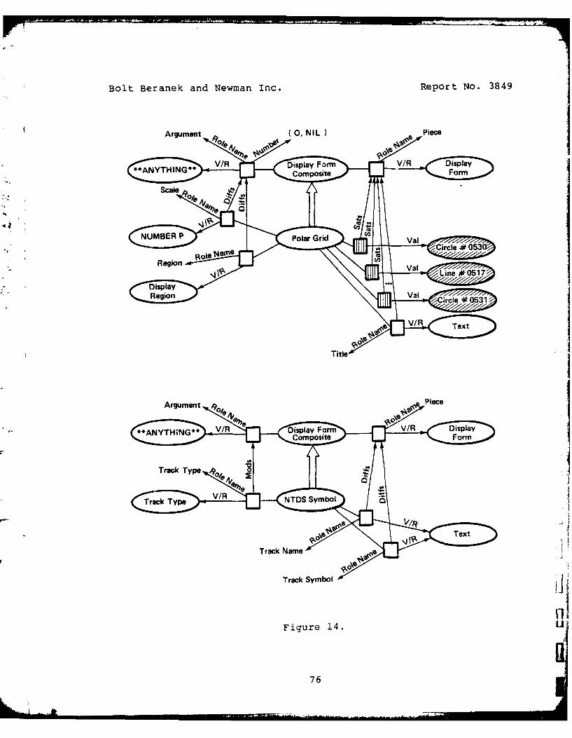
Bolt Beranek and Newman Inc. Report No. 3849
Argument(0NIPic
AVHG V/R Display Form V/ Display
rCmpie isia
NUMBERrac SmbolarGia
Figure 04.53
Role t~76

Report No. 3849 Bolt Beranek and Newman Inc.
symbol. Instead of the standard alphanumeric characters, this
font set will link each character code to an icon, a small
picture contained in a single character cell.
To see how these descriptions function to create a display,
consider the situation shown in Figure 15, wherein we already
have an instance of FORMATION (in this case, FORMATION#0151) with
filled in Roles. This is the group of tracks to be included in
the final map. The user (either directly or indirectly, through
some program) begins the map drawing process by causing an
individual of FORMATIONMAP (FORMATIONMAP#0213) to be created
whose FormationBody Role is filled by FORMATION#0151.
The "WHEN-KLIndividuate" IHook attached to FORMATIONMAP
fills the new individual's PrettyInjection Role with an instance
of INJECTION whose ViewSurface, CoordinateSystem and
DisplayRegion roles are (for the simplicity of this example)
program constants of the IHook. It then maps over the fillers of
the Track Role in FORMATION#0151, examining their Location Roles,
to determine an appropriate scale for the map. This is used to
compute the CoordinateSystemMapping Role of the injection, and is
saved for later use at FORMATION#015i"s Scale Role.
FORMATIONMAP's individuation IHook then begins the process of
mapping over the fillers of FORMATION#0151s Track Role, adding
fillers to FORMATIONMAP#0213's TrackPresentation Role, and then
finishes by filling the GridPresentation Role.
As each filler of FORMATIONMAP#0213's TrackPresentation Role
is individuated, the "WHEN-KLIndividuate" IHook on
TRACKPRESENTATION fires which fills in the Style Role with an
instance of NTDSSYMBOL according to the name and type of thetrack. Following this, the "WHEN-KLIndividuate" IHook on
PRESENTATION causes the new instance of TRACKPRESENTATION to
become a filler of the display region's Occupant Role. Finally,
77

Bolt Beranek and Newman Inc. Report No. 3849
C ~
78
C 4

Report No. 3849 Bolt Beranek and Newman Inc.
the "WHEN-KLSatisfyRole" IHook on Occupant causes the new
occupant to be drawn by finding the appropriate "HowToDraw"
information attached to the Generic Concept TEXT.
When all of the fillers of FORMATIONMAP#0213 sTrackPresentation Role have been determined, the individuation
IHook on FORMATIONMAP goes on to fill the GridPresentation Role
with a new instance of GRIDPRESENTATION. This causes another
*'- "WHEN-KLIndividuate" IHook to fire, for the purpose of filling
the new Individual Concept's DomainObject, Style and InjectionRoles. An instance of GRIDLOCUS is created to fill the
DomainObject Role. The "WHEN-KLIndividuate" IHook on
GRIDPRESENTATION finds the filler for the grid locus' Location
Role by looking at the Location Role of FORMATION#0151's Flagship
Role filler. Next, the new presentation's Style Role is filled
with an instance of POLARGRID with appropriately filled Scale and
Region Roles. Finally, GRIDPRESENTATIONOs "WHEN-KLIndividuate"
IHook causes the Injection Role to be filled with a copy of
FORMATIONMAP#0213"s PrettyInjection Role filler whose coordinate
transformation function is derived so as to just map a grid of
unit circle size and flagship track location onto the destination
display region. With the role filling process at
GRIDPRESENTATION complete, the "WHEN-KLIndividuate" IHook on
PRESENTATION fires to add mapped versions of POLARGRID's Piece
Role fillers to the Occupant Role of the destination display
region, thus indirectly causing them to be drawn.
One thing to note in this example is that it actually
requires very little procedural knowledge to be added to the
pre-existing AIPS network. Most of what is needed is already
there. The only substantial additions involved are a procedure
for computing an appropriate scale for the map based on the
spread in the world locations of the tracks, and a procedure for
deriving the appropriate coordinate transform for the reference
79

Bolt Beranek and Newman Inc. Report No. 3849
grid according to the size of the destination display region.
Furthermore, significant changes can be made to the display
via only minor and isolated modifications to the underlying [jdescription. The contents of the map, for example, can be easily
changed by modifying the Roles of the Generic Concept FORMATION,
or by adding Roles to the Concepts TRACK and TRACKPRESENTATION.
It is also an easy task to change the type of reference grid used
in the map by defining a new display form to take the place of IPOLARGRID. Thus, even at this rudimentary state of development,
the use of declarative representation and procedural attachment
has already made a substantial contribution to the flexibility of
the display management system. The IHook triggering mechanism
does add an extra level of indirection to the task of following
the flow of control, but this is more than offset by the
factor ization of the system's knowledge enforced by the use of a
taxonomic conceptual network.
80
iA -il

Report No. 3849 Bolt Beranek and Newman Inc.
7. THE MIDDLE EARTH DEMONSTRATION SYSTEM
In this section, we will give a brief description of one of
the demonstration systems, called Middle Earth, that we have
implemented using AIPS. The context for this system is an Over
the Horizon (OTH) targeting task in which tracks of enemy and
friendly ships are entered onto a map, projected forward in time,moved as necessary, and assigned as the targets and launch
vehicles for Tomahawk missiles. In fact, this demonstration
system contains no knowledge about the OTH targeting problem.
Instead, it is a kind of computer-assisted sketch pad for drawing
a certain sort of target assignment diagram.
• . ",;NowFriendShip
" NewEnemyShip
,, Mcve~hip
/ Pr ojectShip
.etMissileTarget
8endMissilePath
EraseMissilePath
SetInformation
HPrintoncept
-i
MakfilErth Menu
Menu ,:,-,mrr\nd plea
Frlemw2V~hlp
,Tomahawktlssfte.F14
Figure 16.
81

Bolt Beranek and Newman Inc. Report No. 3849
The Middle Earth demonstration system is described in terms
of six display regions. Four of these are on the screen view
surface that represents the Conrac video monitor. The other two
are on the screen view surface for the General Turtle display.
Included on the Conrac are a map display region labelled Middle
Earth, a Legend display region that contains a key to the map
symbols, a Menu display used for controlling the demonstration
program, and a Prompt display region in which the system prints
prompting messages to the user. The General Turtle display
contains a large general purpose text region and a much smallersystem status region along the top edge of the screen. The
former is used for printing some responses to the user's menu
commands and for all interaction with the Inter lisp interpreter.
The latter contains a dynamically updated, one-line report on thepresence of un-read electronic mail, system and group load
average, and the currently connected directory.
Only three of the display regions are described as fullgraphics display regions. These are the Middle Earth, Legend and
Menu regions on the Conrac. The other three are described as
instances of TEXTDISPLAYREGION. Display forms are drawn on the
graphics regions by adding the display form to be drawn to thegraphics region's Occupant Role. Text is sent to the text
display regions by ad hoc selection of the desired region with
the function BMGTTYRegion and resort to the usual Interlisp print
functions.
The Middle Earth map display region is initialized with some
instances of DISPLAYFORM already in place. These are the
individuals of POINTSLISTDISPLAYFORM that outline the island of
Sicily and the "toe" and "heel" of the Italian boot. The Legend
region is initialized with an instance of each of the map symbols
coupled with a line of text indicating what the symbol isintended to represent. Each map symbol is an instance of TEXT in
82

Report No. 3849 Bolt Beranek and Newman Inc.
which the Font Role specifies a special font set whose characters
are small pictograms. The Menu display region contains nine
lines of text, each of which can be selected by input from the
graphic tablet. These represent various user commands to the
demonstration program.
The first two options in the menu display region, which are
tagged with the strings "NewFriendShip" and "NewEnemyShip", allow
the user to insert symbols for friendly and enemy ships onto the
map. The system first prints a prompting message requesting the
user to input the desired location for the new track. When this
has been done using the graphic tablet, a new instance of either
FRIENDLYSHIPDF or OTHERSHIPDF (descendants of DISPLAYFORM) is
added to the Occupant Role of the map display region, and thus
drawn. The third menu item, denoted "MoveShip", allows the user
to change a ship's location. With two successive prompts, the
system asks the user to identify the ship to be moved and its new
location, using the graphic tablet. The designated display form
is then moved, and any other necessary changes to the map are
made. For example, if the ship display form being moved is
connected to one end or the other of a missile path display form,
the path display form is adjusted to connect to the new location.
"ProjectShip", the fourth menu item, lets the user specify
the projected location of a target ship at time of impact. The
user is prompted to input the identity of the ship to be
projected, and then the location that it is being projected to.
The result on the display is a dashed circle at the projection
location, connected to the ship symbol with a dashed arrow.
Missile path forms, incidentally, are constrained to terminate atthe destination end at some projection of a ship and never
directly at a ship symbol. The fifth menu item,
"SetMissileTarget", allows the user to specify a missile path
between an attacker and a target. He or she is first prompted to
83

Bolt Beranek and Newman Inc. Report No. 3849
L
point at the attacking ship symbol, then the projected target
symbol, and then a location for the elbow of a two-leg missile
flight path. The missile path is drawn in the map display region
as two straight lines connecting a ship symbol with a projection
symbol, with a third symbol representing a Tomahawk missile at
the join between them. The "BendMissilePath" menu option allows
the user to change the location of the elbow of a missile path.
First the path is pointed at and then the new location. The path
is erased and then re-drawn to bend as specified.
"EraseMissilePath" causes a designated path to be removed.
The "SetInformation" and "PrintInformation" items allow
arbitrary strings input from the terminal to be attached to
designated display forms. The last menu item, "PrintConcept",
can be used to cause the KLONE concept associated with any
visible display form to be printed in the general purpose text
region on the General Turtle display.
84

Report No. 3849 Bolt Beranek and Newman Inc.
8. CONCLUSION
This first year's effort has seen a number of important
milestones in our exploration of a symbolic processing paradigm
for command and control. Perhaps the most important of these is
that a specific problem area has been selected to concentratefurther incremental development of experimental systems:
knowledge-based display managem-nt. This problem is central to
the investigation of the paradigm, is of practical importance in
the context of current C2 systems, and manifests a spectrum of
issues in the construction of real-time, knowledge-based systems.
This project has helped to develop a powerful tool for
building such systems: the KLONE knowledge representation
language. In fact, AIPS is among the,/ very first attempts of any
extent to use KLONE, and this us6 has been instrumental in
identifying problems with early versions of the language and
driving its further refinement. An initial implementation of a
prototype AIPS system was completed, and the results used to
realize a pair of demonstration systems in widely differing
domains. This initial set of descriptions and procedural
attachments comprises a healthy nucleus for further growth.
At its inception, this effort was predicated on the
availability of powerful and capacious symbolic processing
hardware such as the MIT Interlisp machine. In fact, resources
of this order did not become available. Nevertheless, an early
demonstration program built around AIPS was made to run on a
prototype LISP machine. That exercise at least established AIPS
as a factual, real-time symbolic processing system. But the fact
also remains that we still do not have this important hardware
resource for system development purposes. Storage space
limitations of the current Interlisp-10 system are becoming a
critical problem.
85

Bolt Beranek and Newman Inc. Report No. 3849
As this report is written, AIPS has already been convertedto run with a new and much expanded version of KLONE. We are
rebuilding the bit-map display processor program so that it can
better support the high-density, interactive, window-oriented
display environments we envision. We are now entering a new
cycle of design and implementation of AIPS proper. Among the
issues we are concerned with are modifications that take
advantage of the improvements to KLONE, reorganization and
expansion of AIPS presentation level into a repertoire of
presentation formats, versatile description and implementation of
display windows, and characterization of AIPS" dynamic behavior
in response to changes in the domain model. We intend to
complete this re-design by implementing a new and more ambitious
demonstration application.
8
.... . 86

Report No. 3849 Bolt Beranek and Newman Inc.
REFERENCES
[Anderson 77]Anderson, R.H., Gallegos, M., Gillogly, J.J.,Greenberg, R.B., and Villanueva, R.RITA Reference ManualThe Rand Corporation, Santa Monica, CA, 1977.
[Bobrow 76]Bobrow, D., and Winograd, T.An overview of KRL, a knowledge representation
language.Technical Report CSL-76-4, Xerox Palo Alto
Research Center, July, 1976.[Brachman 77a]
Brachman, R.J.What's in a concept: Structural foundations for
semantic networks.International Journal of Man-Machine Studies 9
:127-152, March, 1977.[Brachman 77b]
Brachman, R.J.A structural paradigm for representing knowledge.PnD thesis, Harvard University, May, 1977.Also, BBN Report No. 3605, Bolt Beranek and Newman
Inc., May 1978.
[Brachman 78a]Brachman, R.J., Ciccarelli, E., Greenfeld, N.R.,and Yonke, M.D.KLONE reference manual.BBN Report No. 3848, Bolt Beranek and Newman Inc.,
July, 1978.tBrachman 78b]
Brachman, R.J.Theoretical studies in natural language
understanding.BBN Report No. 3888, Bolt Beranek and Newman Inc.,
September, 1978.[Brachman 79]
Brachman, R.J.On the epistemological status of semantic
networks.In N.V. Findler, editor, Associative Networks --
the Representation and Use of Knowledge inComputers, pages 3-50. Academic Press, NewYork, 1979.
87

Bolt Beranek and Newman Inc. Report No. 3849
[Brandenberg 77]Brandenberg, R., Gallegos, M., Hayes-Roth, R., andWaterman, D.RITA threat evaluation and countermeasures agent.1977.Working paper.
[Cercone 75a]Cercone, N.Representing natural language in extended semantic
networks.Technical Report TR75-11, Department of Computing
Science, The University of Alberta, July, 1975.(Cercone 75b]
IJCAI, Tbilisi, Georgia, USSR.Toward a state based conceptuzl representation,
1975.[Fahlman 77]
Fahiman, S.C.A system for representing and using real-world
knowledge.PhD thesis, Massachusetts Institute of Technoloqy,
June, 1977.[Hartley 79]
Hartley, A.K.Interlisp-1_.BBN Report No. 4076, Bolt Beranek and Newman Inc.,
March, 1979.(Hendrix 75a]
Hendrix, G.G.Partitioned networks for the mathematical modeling
of natuaT language semantics.Tech-nical Report NL-28, Department of Computer
Sciences, The University of Texas at Austin,December, 1975.
(Hendrix 75b]IJCAI, Tbilisi, Georgia, USSR.Expanding the utility of semantic networks through
partitioning, 1975.(Martin 77]
IJCAI, Cambridge, MA.OWL, 1977.
(Roberts 771Roberts, R.B., and Goldstein, I.P.The FRL ManualMassachusetts Institute of ;echnology Artificial
Intelligence Laboratory, Cambridge, MA, 1977.MIT AI Lab Memo 409.
bS

Report No. 3849 Bolt Beranek and Newman Inc.
(Sandewall 781Sandewall, E.Programming in the interactive environment: the
Lisp experience.Computing Surveys 0(1)0:35-71, March, 1978.
(Schank 72]Schank, R.C.Conceptual dependency: A theory of natural
language understanding.Cognitive Psychology 3:552-631, 1972.
[Schank 73a]Schank, R.C.The conceptual analysis of natural language.In Randall Rustin, editor, Natural Langauge
Processing, pages 291-309. Algorithmics Press,New York, 1973.
(Schank 73b]Schank, R.C.Identification of conceptualizations underlying
natural language.In Roger C. Schank and Kenneth Mark Colby, editor,
Computer Models of Thought and Language, pages187-247. W.H. Freeman and Co., San Francisco,1973.
[Schank 74]Schank, R.C., and Rieger, C.J.Inference and the computer understanding of
natural language.Artificial Intelligence 5(4):373-412, Winter,
1974.(Schubert 76]
Schubert, L.K.Extending the expressive power of semantic
networks.Artificial Intelligence 7(2):163-198, Summer,
1976.[Shapiro 71]
Shapiro, S.C.The MIND system: A data structure for semantic--information processIng.
Technical Report R-837-PR, The Rand Corporation,August, 1971.
[Shapiro 75]Shapiro, S.C.An introduction to SNePS.Technical ReportT-Comp-uTer Science Department,
Indiana University, March, 1975.
89

Bolt Beranek and Newman Inc. Report No. 3849
[Shapiro 77][Shapiro,
S.C.Representing and locating deduction rules in a
semantic network.SIGART Newsletter (63):14-18, June, 1977.i [Smith 78]
SSmith, Brian C.
Levels, layers, and planes: The framework of asystem of knowledge representation semantics.
Master's thesis, Massachusetts Institute ofTechnology, 1978.
[Szolovits 77]Szolovits, P., Hawkinson, L.B., and Martin, W.A.An overviewof OWL, a language for knowledge
Technical Report MIT/LCS/TM-86, MassaschusettsInstitute of Techonology Laboratory forComputer Science, June, 1977.
- - [Teitelman 78]Teitelman, W.
* IINTERLISP Reference ManualRevised October 1978 i1tTon, Xerox Palo Alto
Research Center, Palo Alto, CA, 1978.(Woods 751
Woods, W.A.What's in a link? Foundations for semantic
networks.In Representation and Understanding: Studies in
Cognitive Science, pages 5-82. AcademicPress, New York, 1975.
*9I* I
90

Report No. 3849 Bolt Beranek and Newman Inc.
91

Bolt Beranek and Newman Inc. Report No.3849
92

Report No. 3849 Bolt Beranek and Newman Inc.
APPENDIX AAIPS KLONE NETWORK
Number of concepts: 73
2DimensionalCoordinateSystem .................652DimensionalPosition......................... .64ATOM.................................7BlackOn~hite .................................63CartesianCoordinateSystem ....................62CartesianPosition ............................ .61Circle ...................................... 46ConnectingLine ...............................44CoordinateDistance ...........................60CoordinateSystem .................... o ..... 59
J ~~CoordinateSystemMapping.. ........ ........ 58CoordinateSystemWindow .......................57CoordinateTransformationFn .. ............ 56Decagon.... ... o.............. o..... ..... 24DEFAULT.o.... .... o..................... 33DEFAULTVALUE ................... o........ 70Der ivedlnjection . ..................... .. .6DerivedPresentation ....................5
-DisplayForm. .... o ......-....... ..... 43DisplayFormComposite.... ........o..... o........42Display-FormPrimitive .........................39DisplayRegion ............... ........ o..... 55Dodecagon.. ...................... o........... 23DomainObject. . .... o.......... -.... o....4
F IXP ..... .......................... 72FLOATP ..... o.............................. 69
Heptagon... o............................ ... .22
Hexagon.: . .. ............. .- . ......... 21HitPosition .... ................... .. .. . .. - 52Injection ............ o .. .. .. . .... -..... o.3
Line.......................... ..... 38L ISPDATA .......... .. . ............ . . ..... 71LISTP...o.. .. o....... ... o....... 41LITATOM ......o..... .. o........... -4Magnitude., .. .. . .. o . ...... o .... ... - .... .68Nonagon ....... o .. . .. o .. .. .. .. .......... .. -.20
* Octagon ... ............ o ............ .. . .. .19
93

Bolt Beranek and Newman Inc. Report No. 3849
Parallelogram. . .. ........... ... . ....... . .. 37Pentagon ............ ......... ........... 18PersistentCircle ....................... 36
h~PersistentText......... ................ 35Point ............. ..................... 3Polygon............................. 32Position ............................... 53Presentation. . ......................... 2PRINTP. .. .. ............................ 67
94
Report No. 3849 Bolt Beranek and Newman Inc.
Projection ................................... 51Quadrilateral ............................... 31Rectangle .................................. 30RegularDecagon ............................... 17RegularDodecagon ............................. 16RegularHeptagon .............................. 15RegularHexagon .............................. 14RegularNonagon .............................. 13RegularOctagon .............................. 12RegularPentagon ............................. 11RegularPolygon ............................. 10RegularSquare ........................... 9RegularTriangle ............................. 8
Rhombus ...................................... 29ScreenViewSurface ............... ........ 50SMALLP .............. .............. 45Square ................................. 28STRINGPo...............................7Text ........................................ 27TextDisplayRegion ............................ 54Trapezoid .................................... 26Triangle ...................................... 25VideoSense ................................... 49ViewSurface .................................. 48WhiteOnBlack ................................. 47
.4
95

Bolt Beranek and Newman Inc. Report No. 3849
[1]
Ponttype: Generic
specializes: NUMBERPis role value of Font{Textl, Font{PersistentTextlhas attached data:
Validity NotTested
[21
Presentationtype: Generichas specializer: DerivedPresentation
V roles:DomainObjectV/R = DomainObjectModality = Obligatory
StyleV/R = DisplayFormModality = Obligatory
InjectionV/R = InjectionModality = Obligatoryis modified by *Iniectionl*{DerivedPresentation}
is role value of FromPresentation{DerivedPresentation}has attached procedures:
(WHEN KLIndividuate NIL)DeriveElaboration
has attached data:Validity NotTested
[31
Injectiontype: Generichas specializer: DerivedInjectionroles:
CoordinateSystemV/R = CoordinateSystemis modified by *CoordinateSysteml*{DerivedInjection} J
DisplayRegionV/R = DisplayRegionModality = Obligatory
CoordinateSystemMappingV/R CoordinateSystemMapping
Modality = (Obligatory Derivable)ViewSurface
96
4 4I"I ill I i ll nl i [ .. . . .. .. .

Report No. 3849 Bolt Beranek arnd Newman Inc.
V/R - ViewSur faceis modified by *ViewSurfacel*tDerivedlniection}
is role value of Fromlnjection{Derivedlnjectionl,Injection{ Presentation}
has attached procedures:(WHEN KLlndividuate NIL)
Afterlndividuatelnjectionhas attached data:
Validity T itTested
[4]
DomainObjecttype: Genericis role value of DomainObject{Presentation}has attached data:
Validity NotTested
(51
DerivedPresentationtype: Genericspecializes: Presentationroles:
*Injectionl*Mods Injection{presentationlV/R = DerivedInjection
FromPresentationV/R = Presentation
has attached data:Validity NotTested
[6]
DerivedInjectiontype: Genericspecializes: Injectionroles:
FromInjectionV/R - Injection
FromProjectionV/R - Projection
*Coord inateSys teml*Mods CoordinateSystem{ InjectionlModality - (Obligatory Derivable)
*ViewSur facel *Mods ViewSurface{ Injection)Modality = (Obligatory Derivable)
is role value of *Injectionl*{DerivedPresentation}
97

iLBolt Beranek and Newman Inc. Report No. 3849
has attached procedures:(PRE KLDeriveRoles NIL)
DeriveDerivedInjectionRoleshas attached data%
Validity NotTested
[7]
STRINGPtype: Genericspecializes: LISPDATA, PRINTP
4 is role value of DisplayMode{DisplayRegion}has attached data:
Validity NotTested
[8]
RegularTriangletype: Genericspecializes: RegularPolygonroles:
*NumberOfSidesl*Mods NumberOfSides{RegularPolygon}VAL = 3
has attached data:Validity NotTested
[91
RegularSquaretype: Genericspecializes: RegularPolygonroles:
*NumberOfSides2*Mods NumberOfSides{RegularPolygon}VAL = 4
has attached data:Validity NotTested
-[10]
RegularPolygontype: Genericspecializes: Polygonhas specializers: RegularTriangle, RegularSquare,
RegularPentagon, RegularHexagon,RegularHeptagon, RegularOctagon,RegularNonagon, RegularDecagon,RegularDodecagon
9

Report No. 3849 Bolt Beranek and Newman Inc.
roles:Center
Diffs ArgumentfDisplayFormcomposite}V/R = 2DimensionalPosition
NumberOfSidesDiffs Argument{DisplayFormcompositelV/R = NTJMBERPis modified by *NumberOfSidesl* RegularTrianglelf
*NumberOfSides2* RegularSquarel,*NumberOfSides3* RegularPentagoni,,*NumberOfSides4* RegularHexagoni
*NumberOfSides5* RegularHeptagonfL*NumberOfSides6* RegularOctagon P*NumberOfSides7* RegularNonagon,*NumberOfSides8* RegularDecagoni,'*N~imberOfSides9* RegularDodecagoni
LengthOfS ideDiffs Argument{DisplayFormComposite}V/R = NtJMBERP
has attached IData:(HowToDraw NIL)
HTDRegularPolygon(HowToFindCenter NIL)
HTFCExpl ic itCenterhas attached data:
Validity NotTested
RegularPentagontype: Genericspecializes: RegularPolygonroles:
*NumberOfS ides3*Mods NumberOfSides{ RegularPolygonlVAL = 5
has attached data:Validity NotTested
[121
RegularOctagontype: Genericspecializes: RegularPolygonroles:
*NumberOfSides6*Mods NumberafSides{ RegularPolygon}VAL =8
has attached data:
99

Bolt Beranek and Newman Inc. Report No. 3849
Validity NotTested
[13]
RegularNonagontype: Genericspecializes: RegularPolygonroles:
*NumberOfSides7*Mods NumberOfSides{ RegularPolygonlVAL = 9
has attached data:Validity NotTested
-14]
RegularHexagontype: Genericspecializes: RegularPolygonroles:
*NumberOfSides4*Mods NumberOfSides{ RegularPolvgon}VAL = 6
has attached data:Validity NotTested
[15]
RegularHeptagontype: Genericspecializes: RegularPolygonroles:
*NumberOfS ides5*Mods NumberOfSides{ RegularPolygon}VAL = 7
has attached data:Validity NotTested
[16]
RegularDodecagontype: Genericspecializes: RegularPolygonroles:
*NumberOfSides9*Mods NumberofSides{RegularPolygoniVAL - 12
has attached data:Validity NotTested
100

Report No. 3849 Bolt Beranek and Newman Inc.
[171
RegularDecagontype: Genericspecializes: RegularPolygonroles:
.I*NumberOfSides8*
Mods NumberOfSides{RegularPolygoni*VAL = 10
has attached data:Validity NotTested
[181
Pentagontype: Genericspecializes: Polygonroles:
*Sidel*Mods Side{Polygon}Number = 5
has attached data:Validity NotTested
[19]
Octagontype: Genericspecializes: Polygonroles:
*Side2*Mods Side{PolygonlNumber - 8
has attached data:Validity NotTested
(201
Nonagontype: Genericspecializes: Polygonroles:
*Side3*Mods Side{Polygon}Number = 9
has attached data:Validity NotTested
101

Bolt Beranek and Newman Inc. Report No. 3849
[21]
Hexagontype: Genericspecializes: Polygonroles:
*Side4*Mods Side{PolygonlNumber = 6
has attached data:Validity NotTested
[22]
Heptagontype: Genericspecializes: Polygonroles:
*Side5*Mods Side{Polygon}Number = 7
has attached data:Validity NotTested
[23]
Dodecagontype: Genericspecializes: Polygonroles:
*Side6*Mods Side{PolygonlNumber = 12
has attached data:Validity NotTested
[24]
Decagontype: Genericspecializes: Polygonroles:
*Side7*Mods SidelPolygon}Number =10
has attached data:Validity NotTested
(251
102

Report No. 3849 Bolt Beranek and Newman Inc.
Triangletype: Genericspecializes: Polygonroles:
*Side8*Mods Side{PolygonlNumber = 3
has attached data:Validity NotTested
[261
Trapezoid
type: Genericspecializes: Quadrilateralhas attached data:
Validity NotTested
127]
Texttype: Genericspecializes: DisplayFormPrimitiveroles:
StringV/R = PRINTP
PositionV/R = Position
FontV/R = Font
is role value of Label{DisplayRegion}has attached IData:
(HowToDraw NIL)HTDText
(HowToErase NIL)HTEText
(HowToFindCenter NIL)HTFCExplicitPosition
has attached data:Validity NotTested
[28]
Squaretype: Genericspecializes: Rectangle, Rhombushas attached data:
Validity NotTested
103

Bolt Beranek and Newman Inc. Report No. 3849
[291
Rhombustype: Genericspecializes: Parallelogramhas specializer: Squarehas attached data:
Validity NotTested
[30]
Rectangletype: Generic
specializes: Parallelogramhas specializer: Squarehas attached data:
Validity NotTested
(311
Quadrilateraltype: Genericspecializes: Polygonhas specializers: Parallelogram, Trapezoidroles:
*Side9*Mods Side{PolygonlNumber = 4
has attached data:Validity NotTested
[321
Polygontype: Genericspecializes: DisplayFormCompositehas specializers: Triangle, Quadrilateral, Pentagon,
Hexagon, Heptagon, Octagon, Nonagon,-J Decagon, Dodecagon, RegularPolygon
roles:SideDiffs Piece{DisplayFormComposite}V/R = LineNumber - (3 NIL)is modified by *Side8*[Triangle},
*Side9* Quadrilaterall,*Sidel*lPentagon, r*Side4*IHexagonl ,*Side5*lHeptagonl, *Side2*t Octagon
104

Report No. 3849 Bolt Beranek and Newman Inc.
*Side3* {Nonagoni, *Side7*{Decagon},
has attached data: *Side6*1Dodecagon1
Validity NotTested
[331
* DEFAULTtype: Generichas attached data:
*Validity NotTested
[341
* Pointtype: Genericspecializes: DisplayFormPrimitiveroles:
Position* V/R - 2DimensionalPosition
has attached IData:(HowToDraw NIL) HDon
(HowToErase NIL)HTEPoint
(HowToFindCenter NIL)HTFCExplic itPosition
has attached data:Validity NotTested
[35]
PersistentTexttype: Genericspecializes: Display~ormPrimitiveroles:
StringV/R - PRINTP
Position* VIE - Position
FontV/R - Font
has attached IData:(NowToDraw NIL)
HTDTex t(HowToErase NIL)
H'TETex t(NowTo~indCenter N!L)
RTFICExplic i tPos it ion
105

Bolt Beranek and Newman Inc. Report No. 3849
has attached data:
Validity NotTested[36]
Pers5is ten tCi r cle- r type: Generic
specializes: DisplayFormPrimitiveroles:
-* CenterV/R - Position
Radius* V/R - CoordinateDistance
has attached IData:(HowToErase NIL)
HTECircle(HowToFindCenter NIL)
STFCExpl ic itCente rhas attached data:
*Validity NotTested
(371
Parallelogram* type: Generic
specializes: Quadrilateralhas specializers: Rectangle, Rhombushas attached data:
Validity NotTested
[38]
L inetype: Genericspecializes: DisplayFormPrimitivehas specializer: ConnectingLineroles:
EndPositionV/R - 2DimensionalPositionNumber -2is modified by *EndPositjonl*{connectingLinel
is role value of SidefPolygon)has attached IData:
(MowToDraw NIL)HTDL inc
(HowToErase NIL)HTELine
(HowToFindCenter NIL)HTFCMidLinePos ition
106

Report No. 3849 Bolt Beranek and Newman Inc.
has attached data:Validity NotTested
(391
DisplayFormPrimitivetype: Genericspecializes: DisplayFormhas specializers: Line, Point, Circle, PersistentCircle,
Text, PersistentTexthas attached data:
Validity NotTested
[40]
LITATOMtype: Generic
* specializes: ATOM, PRINTPhas attached data:
Validity NotTested
[41]
LISTPtype: Genericspecializes: LISPDATAhas attached data:
Validity NotTested
(42]
DisplayFormCompositetype: Genericspecializes: DisplayFormhas specializer: Polygonroles:
Argumentis differentiated by Center[RegularPolygon},
NumberOfSides{RegularPolygon},LengthOfSide{RegularPolygonl
PieceV/R a DisplayFormis differentiated by Side{Polygonl
has attached IData:(HowToDraw NIL)
HTDComposite(HowToErase NIL)
HTEComposite(HowToFindCenter NIL)
107

Bolt Beranek arnd Newman Inc. Report No. 3849
HTFCCenterOfPieces(HTCDistanceSquaredFromDF NIL)
HTCDistanceDFComposi tehas attached data:
Validity NotTested
[43]
DisplayFormtype: Generichas specializers: DisplayFormPrimitive,
Di splayFormCompos iteis role value oE Piece{DisplayFormcomposite,
Displayrorm{ ConnectingL inclStylelPresentation},Occupant{ DisplayRegionl
has attached data:Validity NotTested
[44]
Connect ingL inctype: Generic
* specializes: Lineroles:
DisplayFormV/R -DisplayFormNumber - 2
*EndPositionl*Mods EndPositionfLine}Modality -(obligatory Derivable)
has attached procedures:(PRE KLDeriveRoles NIL)
Der iveConnectingLinePositionshas attached data:
Validity NotTested
[451
SMALL Ptype: Genericspecializes: NUMBERPhas attached data:
Validity NotTested
[46]
Circle
type: Generic
108

Report No. 3849 Bolt Beranek and Newman Inc.
specializes: DisplayForniPrimitiveroles:
CenterV/R - 2DimensionalPosition
RadiusV/R - Magnitude
has attached IData:(HowToDraw NIL)
HTDCircle(HowToErase NIL)
HTECircle(HowTo~indCenter NIL)
HTFCExpl ic itCenterhas attached data:
Validity NotTested
[471
WhiteOnBlacktype: Genericspecializes: VideoSensehas attached data:
Validity NotTested
[48]
ViewSur facetype: Generichas specializer: ScreenViewSurfaceroles:
CoordinateSystemV/E - CartesianCoordinateSystem
is role value of FromSurface{projectionl,ToSurface{ projection}ViewSurface{ Injections
has attached data:Validity NotTested
(491
VideoSensetype: Generichas specializers: BlackOnWhite, WhiteOnBlackis role value of VideoSense{ScreenViewSurface}has attached data:
Validity NotTested
[501
109

Bolt Beranek and Newman Inc. Report No. 3849
ScreenViewSurfacetype: Genericspecializes: ViewSurfaceroles:
VideoPlaneV/R = NUMBERP
VideoSenseV/R = VideoSense
FullScreenDisplayRegionV/R = DisplayRegion
is role value of Screen{DisplayRegion}has attached procedures:
(WHEN KLIndividuate NIL)SetScreenVideoSense
has attached data:Validity NotTested
[51]
Projectiontype: Genericroles:
FromSurfaceV/R = ViewSurface
ToSurfaceV/R = ViewSurface
CoordinateSystemMappingV/R = CoordinateSystemMapping
is role value of FromProjection{DerivedInjectionhas attached procedures:
(WHEN KLIndividuate NIL)DeriveInjectionAfterIndividuateProlection
has attached data:Validity NotTested
[52]
HitPositiontype: Genericspecializes: CartesianPositionhas attached data:
Validity NotTested
(53]
Positiontype: Generichas specializer: 2DimensionalPositionroles:
110

Report No. 3849 Bolt Beranek and Newman Inc.
CoordinateVIE - NUMBERPis differentiated by X{ 2DimensionalPositionj
Y {2DimensionalPosition jis role value of Position{CoordinateSystem},,
1,11 CoordinateTransformationFn 10,01 CoordinateTransformationFn i,UpperRightlcoordinatesystemwindlowl,LowerLeft(CoordinatesystemWindow},Cerlter{PersistentCirclel, Position{Text},Position{ PersistentTextj
has attached data:4Validity NotTested
(541
TextDi splayReg iontype: Genericspecializes: DisplayRegionroles:
InnerReg ionNumberV/R = NUMBERPModality =(Obligatory Derivable)
has attached procedures:(WHEN KLlndividuate TextDRLockOut)
AfterlndividuateTextDi splayRegionhas attached data:
Validity NotTested
[55]
Di splayReg iontype: Generichas specializer: TextDisplayRegionroles:
ScreenV/R - ScreenViewSurface
WindowV/R - CoordinateSystemWindow
BackgroundV/R - NUNEERP
Req ionNumberV/R - NU!4BERP
DisplayModeVIE STRINGP
LabelV/R - Texthas attached procedures:
(WHEN KLSatisfyRole NIL)

Bolt Beranek and Newman Inc. Report No. 3849
$ AfterSatisfyLabeiRole(WHEN KLChangeRoleValue NIL)
AfterChangeLabeiRoleOccupantV/R = DisplayFormNumber = (0 NIL)has attached procedures:
(WHEN KLSatisfyRole NIL)is roe vale ofAfterSatisfy~ccupaitRole
4 FullScreenDisplayRegion{ screenViewsurface}DisplayRegiont InjectiorU
has attached procedures:(WHEN KLlndividuate TextDRLockOut)
AfterlndividuateDi splayRegionhas attached data:
Validity NotTested
[56]
CoordinateTransforma tionFntype: Genericroles:
V/R = Position0,0V/R - Position
is role value of
CoordinateTransformationFn{CoordinateSystemmappingIhas attached data:
Validity NotTested
[57]
Coordina teSys temWindowtype: Genericroles:
UpperRightV/R - Position
LowerLeftV/R -Position
is role value of WindowjDis layRegion},FromWindow jCoordinateSystemMapping},IToWindow{ CoordinateSystemmapping}
has attached data:Validity NotTested
112

Report No. 3849 Bolt Beranek and Newman Inc.
[58]
CoordinateSysteniMappingtype: Genericroles:
FromWindowV/R m:CoordinateSysteniWindow
ToWindow4 V/R -CoordinateSysteniWindow
CoordinateTransformationFnV/R -CoordinateTransformationFn
InverseMappingV/R -CoordinateSystemMappingModality = (obligatory Derivable)
is role value of CoordinateSysternMapping{Projection},InverseMapping{coordinatesystemmappingI},CoordinateSystemMapping{ InjectionI
has attached procedures:(WHEN KLlndividuate NIL)
AfterindividuateCoordinateSystemMappinghas attached data:
Validity NotTested
[59)
CoordinateSystemtype: Generichas specializer: 2DimensionalCoordinateSysten4roles:
PositionV/R -Position
is role value of CoordinateSystem{ CoordinateD istancei,CoordinateSys tern iInjection}
has attached data:Validity NotTested
[601
CoordinateDistancetype: Genericroles:
CoordinateSystemV/R = CoordinateSystem
MagnitudeV/R - NUMBERP
is role value of Radius{PersistentCircilhas attached data:
Validity NotTested
113

Bolt Beranek arnd Newman Inc. Report No. 3849
[61]
CartesianPositiontype: Genericspecializes: 2DimensionalPositionhas specializer: HitPositionroles:
AbcissaDiffs X12DimensionalPosition}
ordinateDiffs Y[2DimensionalPositionl
has attached data:Validity NotTested
[62]
Car tesianCoordinateSystemtype: Genericspecializes: 2DimensionalCoordinateSystemis role value of CoordinateSystem{viewsurface}has attached data:
Validity NotTested
[63]
BlackOnWhi tetype: Genericspecializes: VideoSensehas attached data:
Validity NotTested
[64]
2DimensionalPosi tiontype: Genericspecializes: Positionhas specializer: CartesianPositionroles:
xDiffs Coordinate{position}is differentiated by Abcissa{CartesiariPosition}
Diffs Coordinate{Position}is differentiated by Ordinate{CartesiaiPositioi}
is role value of EndPosition{Linel, PositionjPoint},Center{Circil}, Center{RegularPolygon)
has attached data:Validity NotTested i
114

*Report No. 3849 Bolt Beranek and Newman Inc.
(651
2DimensionalCoordinateSystemtype: Genericspecializes: CoordinateSystemhas specializer: CartesianCoordinateSystemhas attached data:
Validity NotTested
(66]
NUMBERPtype: Generic
:1 specializes: ATOM* has specializers: FIXP, FLOATP, SMALLP, Magnitude, Font
is role value of Magnitude{CoordinateDistance},Coordinate{ Position},VideoPlaneiScreenViewSurface},Backgroundi{DisplayRegion],RegionNuinber{ Disp'layRegioni,
NurberOfSidesRegularPolygnl,LengthOfSide{ RegularPolygon}
has attached data:Validity NotTested
[671
PRINTPtype: Generichas specializers: LITATOM, STRINGPis role value of String{Text}, String{PersistentTextlhas attached data:
Validity NotTested
[68]
magnitudetype: Genericspecializes: NUMBERPis role value of Radius{Circle}has attached data:
Validity NotTested
(69]
FLOATPtype: Genericspecializes: NUMBERP
115
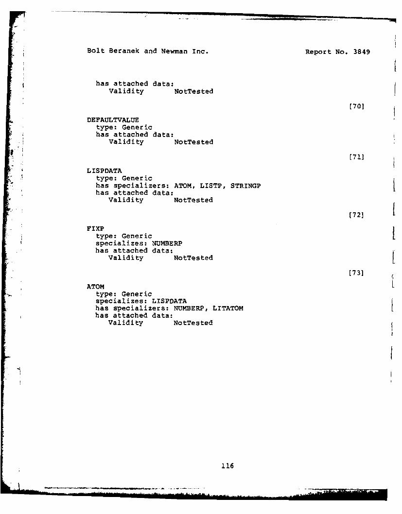
Bolt Beranek and Newman Inc. Report No. 3849
has attached data:Validity NotTested
(701
DEFAULTVALUEtype: Generichas attached data:
Validity NotTested
*. [71]
LISPDATAtype: Generichas specializers: ATOM, LISTP, STRINGP ihas attached data:Validity NotTested
(72]
FIXPItype: Genericspecializes: NUMBERPhas attached data:
Validity NotTested
[73]
ATOM Ltype: Genericspecializes: LISPDATAhas specializers: NUMBERP, LITATOMhas attached data:
Validity NotTested
116
"~-..............,

Report No. 3849 Bolt Beranek and Newman Inc.
APPENDIX BBIT MAP GRAPHICS FUNCTIONS
BMGGraphicsRegion(Region)
- Sets the graphics region to be Region.
BMGTTYRegion(Region)
- Sets the TTY region for all following operations.If Region is negative, the local, printingterminal is used instead of a bitmap region.
BMGResetTTY()
The TTY region is cleaned, filled with itsbackground shade, and the current point set atthe left boundary ready to start the first lineof text.
BMGVideoDefault(Mode)
- Sets the sense of the video signal. Mode refersto the backgraound: BLACK or WHITE.
BMGVideoSense(Plane,Mode)
- Sets the sense of the video on plane Plane toMode. Mode is either BLACKONWHITE orWHITEONBLACK.
BMGLimits(MaxX,MinX,MaxY,MinY)
- Sets the boundaries of the graphics region.
117
.. ... ... ..... .... ... ..L;::: ,2 .. ..."+ i.... .Z + ... ...... ..ii ,-:'-. . .

Bolt Beranek and Newman Inc. Report No. 3849
BMGPlane(Plane)
- Sets the plane of the graphics region to bePlane. Currently 0 is the General Turtle monitor(12", P39 phosphor), and 1 is the CONRAC monitor(17", P4 phosphor).
BMGRelativeCoordinates(Flag)
If Flag is non-NIL, then graphics operations inthe current graphics region will be understood inrelative coordinates. If Flag is NIL, then screencoordinates will be used.
BMGB ias (XY)
- Sets the bias (origin) of the current graphicsregion to (X Y).
BMGDisplayMode(Mode)
- Sets the display mode of the graphics region.Mode is one of ADD, REMOVE, FLIP, OVERWRITE.
BMGFont(Font)
- Sets the font of the graphics region. Font is asmall integer.
BMGTTYFont(Font)
- Sends font change escapse sequence down the TTYstream.
[
118

Report No. 3849 Bolt Beranek and Newman Inc.
BMGScroll(Distance)
Sets the scrolling characteristics of thegraphics region. Distance is the number of linesto scroll up at a hop; if Distance is zero, thewhole region is cleaned instead of scrolling.
BMGBackground(Grey)
Sets the background shade of the graphics region.Grey is a 16-bit integer describing a 4 by 4pattern of bits: the bits of the top line of thispattern are the low-order 4 bits of Grey, thesecond line provides the next 4 bits, and so on;thus 0 means no bits, -1 means all bits, 122643Qis every other point, and 116143Q is top-right tobottom-left slashes.
BMGFill(Grey)
The graphics region is filled with the pattern ofshading indicated by Grey (see BMGBackGround).The filling is affected by display mode(OVERWRITE is not the same as ADD).
BMGRelocateRegion(X,Y)
- Translates the graphics region so that its topleft corner is at (X,Y). This moves all the bitsin the region and changes its limits.
119

-I
Bolt Beranek and Newman Inc. Report No. 3849
iU
BMGMoveRegion(FromRegion,ToRegion)
The ToRegion is filled with the contents of theFromRegion. The top left bits of FromRegion aredrawn into the top left bits of the ToRegion.The boundaries of the ToRegion determine how muchis moved; the boundaries of the FromRegion areignored. The filling is affected by the displaymode of the ToRegion.1
BMGMove (X,Y) 1Mikes (X,Y) the current point of the graphicsregion.
BMGMoveRelative(DeltaX,DeltaY)
- Like BMGMove, except that the point moved to isthe vector sum of (DeltaX,DeltaY) and the currentpoint. 1
BMGPoint (X,Y)
Draws a point at (X,Y). If outside the graphicsregion it does not appear. Note that "drawing" isdone in the display mode of the graphics region L(in this case, OVERWRITE has the same effect asADD).
BMGPointRelative(DeltaX,DeltaY)
- Like BMGPoint, except that the point at which thepoint is drawn is the vector sum of(DeltaX,DeltaY) and the current point.
1I
120

Report No. 3849 Bolt Beranek and Newman Inc.
BMGL ine (X, Y)
Draws a line from the current point of thegraphics region to (XY). Sets the current pointto be (X,Y). If outside the graphics region, itis clipped. Drawing is affected by display mode(see BMGPoint).
* BMGLineRelative(DeltaX,DeltaY)
- Like BMGLine, except that the line is drawn (from-the current point) to the vector sum of
(DeltaX,DeltaY) and the current point.
BMGCircle(X,Y,R)
- Draws a circle with no change to the currentpoint.
BMGEllipse(X,Y,A,B)
- Draws a horizontal or vertical ellipse by a setof straight lines, the number dependent on thesize of the ellipse.
121
L./

Bolt Beranek and Newman Inc. Report No. 3849
BMGStr ing (Text)
PRIN3 is applied to Text. The result is drawn atthe current point of the graphics region.Characters outside the graphics region do notappear. The current point of the graphics regionis left at the end of the text: that is, use ofthis function without intervening movement of thecurrent point of the graphics region will appendcharacters to the drawn characters in areasonable way. Formatting characters do not havea formatting effect; they are drawn as a pattern LIof bits just as every other character is. Drawingis affected by display mode (OVEWRITE is not thesame as ADD).
BMGGetCurrentPosition()
- Gets the current xy position in the currentgraphics region.
BMGGetStringSize(String)
Returns a pair with the maximum length of thestring in bit positions as if printed in thecurrent graphics region with its current font.The y coordinate is the font height times thenumber of line feeds in the string.
BMGTTYCursor(Flag)
- Activates (or deactivates) the TTY cursor.
BMGTablet (How)
- Activates or deactives the tablet.
122

Report No. 3849 Bolt Beranek and Newman Inc.
BMGTabletPlane(Plane)
- Sets the plane for the tablet cursor.
BMGTabletCursorShape(UpShape,DownShape)
- Changes the cursor shape. UpShape and DownShape arearrays of (at least) 20 words: 16 for the raster, andone each for offsetx, offsety, height, and width.
BMGGetHit()
- Waits for and returns a hit pair: CAR is X, CDRis Y.
BMGPrintOperations(Flag)
For debugging: if Flag is non-NIL, then the BMGoperations cause printout on the terminal (ifyou're using the 8MG at the time, this will be inthe TTY region). If Flag is NIL, BMG operationswill begin to have their BMG effect.
12361 L