Embed Size (px)
Citation preview

BY ORDER OF THE COMMANDER
INCIRLIK AIR BASE (USAFE)
INCIRLIK AIR BASE INSTRUCTION
13-204
29 JUNE 2016
Nuclear, Space, Missile, Command
and Control
AIRFIELD OPERATIONS
COMPLIANCE WITH THIS PUBLICATION IS MANDATORY
ACCESSIBILITY: Publication and forms are available on the e-Publishing web site at
www.e-Publishing.af.mil for downloading or ordering
RELEASABILITY: There are no releasability restrictions on this publication
OPR: 39 OSS/OSA
Supersedes: INCIRLIKABI13-204,
21 March 2013
Certified by: 39 OSS/CC
(Lt. Col Kyle J. Wilson)
Pages: 59
The procedures in this instruction implement Air Force Policy Directive (AFPD) 13-2, Air
Traffic Control, Airspace, Airfield and Range Management; and references Air Force Instruction
13-204, Volume 3, Airfield Operations, Procedures and Programs; International Civil Aviation
Organization (ICAO) Doc 4444, Air Traffic Management; Federal Aviation Administration
Order JO 7110.65, Air Traffic Control; AFI 13-213, Airfield Driving; Turkish AIPs; Defense
Economic Cooperation Agreement (DECA); applicable MAJCOM supplements, Standard
Operating Procedures and letters of agreement with the host nation. This instruction establishes
procedures for airfield and control of air traffic operations in support of flying missions at
Incirlik Air Base (IAB), Turkey. This publication applies to all DoD components including the
Air Force Reserve and Air National Guard (ANG), operating out of Incirlik AB. This publication
may not be supplemented. Refer recommended changes and questions about this publication to
the Office of Primary Responsibility (OPR), (39 OSS/OSA), using the AF Form 847,
Recommendation for Change of Publication; route AF Forms 847 from the field through the
appropriate chain of command. Submit requests for waivers through the chain of command to the
39 OSS/OSA. Ensure that all records created as a result of processes prescribed in this
publication are maintained in accordance with AFMAN 33-363, Management of Records, and
disposed of in accordance with the Air Force Records Information Management System
(AFRIMS) Records Disposition Schedule (RDS).

2 INCIRLIKABI13-204 29 JUNE 2016
SUMMARY OF CHANGES
This document is substantially revised and must be completely reviewed. Changes within this
rewrite include: aircraft priorities; reduced-same-runway separation; radar in-trail procedures;
Surety operations; jettison of external stores and model aircraft procedures.
Chapter 1— INTRODUCTION AND POLICY 7
1.1. Overview. ................................................................................................................ 7
1.2. Airfield Operations Board (AOB). ......................................................................... 7
Table 1.1. Quarterly. ................................................................................................................ 7
Chapter 2— INCIRLIK AIR BASE AIRFIELD AND AREA DESCRIPTION 9
2.1. Location and Field Elevation. ................................................................................. 9
2.2. Airfield Operations Facilities and Hours of Operation. .......................................... 9
Table 2.1. Incirlik AB Frequencies. ......................................................................................... 10
2.3. Navigational Aids (NAVAIDs). ............................................................................. 10
2.4. Local Flying Areas. ................................................................................................. 10
2.5. Runway, Taxiways, Ramps, Restricted Areas, and Permanently Closed Portions
of the Airfield. .......................................................................................................... 12
2.6. Aircraft Arresting Systems/Barriers. ...................................................................... 13
2.7. Controlled Movement Area (CMA) (Attachment 2). ............................................. 13
2.8. Visual and Radio Blind Spots. ................................................................................ 14
2.9. Precision Approach Critical Areas and Instrument Hold Lines. ............................. 14
2.10. Airfield Lighting. .................................................................................................... 15
Chapter 3— EMERGENCIES 16
3.1. Emergency Frequencies. ......................................................................................... 16
3.2. Declaration of Emergencies. ................................................................................... 16
3.3. Primary Crash Alarm System (PCAS). ................................................................... 16
3.4. Secondary Crash Net (SCN). .................................................................................. 17
3.5. Suspending/Resuming Runway Operations During Emergencies. ......................... 17
3.6. Personnel/Crash Locator Beacon Signal/Emergency Locator Transmitter (ELT)
Response Procedures. .............................................................................................. 18

INCIRLIKABI13-204 29 JUNE 2016 3
3.7. Hijack/Unlawful Seizure of Aircraft/Stop Alert Procedures. ................................. 18
3.8. Unscheduled/Unauthorized Aircraft Arrivals. ........................................................ 18
3.9. F-16 Emergency Power Unit (EPU)/Hydrazine Incidents. ..................................... 18
3.10. Hot Brake Area and Procedures. ............................................................................. 19
3.11. Hung Ordnance or Hung Guns. .............................................................................. 19
3.12. Bailout. .................................................................................................................... 19
3.13. Use of LTD-13 for External Stores Jettison and Fuel Dumping. ............................ 19
3.14. Explosive Detection Military Working Dog (MWD)/K-9 Teams. ......................... 19
3.15. Emergency and Mishap Response. ......................................................................... 20
3.16. Emergency Aircraft Arresting System Procedures. ................................................ 20
3.17. Evacuation of ATC and AM Facilities. .................................................................. 20
Chapter 4— AIRFIELD OPERATIONS 22
4.1. Airfield Coordination/Closure Procedures.............................................................. 22
4.2. Prior Permission Required (PPR) Procedures. ........................................................ 22
4.3. Transient Alert (TA) Services. ................................................................................ 22
4.4. Notice to Airman (NOTAM) Procedures. .............................................................. 23
4.5. Flight Planning. ....................................................................................................... 23
4.6. Classified Material. ................................................................................................. 23
4.7. 39 CES Responsibilities. ......................................................................................... 23
Table 4.1. Airfield Sweeper Priorities. .................................................................................... 26
4.8. MXS Responsibilities ............................................................................................. 26
Table 4.2. Aircraft Engine Run Procedures. ............................................................................ 27
4.9. Aircraft Parking Plan. ............................................................................................. 29
4.10. Pantograph Refueling. ............................................................................................ 30
4.11. Airfield Conditions, Hazards, Inspections, and Checks. ......................................... 30
4.12. Runway Surface Condition (RSC) and Runway Condition Reading (RCR). ......... 31
4.13. Weather Procedures. ............................................................................................... 31
4.14. Bird and Wildlife Aircraft Strike Hazard (BASH) Procedures. .............................. 31
4.15. Flight Information Publication (FLIP) Accounts. ................................................... 31

4 INCIRLIKABI13-204 29 JUNE 2016
4.16. Wear of Hats and Airfield Smoking Procedures. .................................................... 32
4.17. Airfield Photography and Videography. ................................................................. 32
4.18. Custodial Control of ATC Tape Recordings. ......................................................... 32
4.19. Exercise Coordination Procedures. ......................................................................... 32
4.20. Quiet Hours for Special Events............................................................................... 32
4.21. Miscellaneous Procedures. ...................................................................................... 33
4.22. Waivers to Airfield and Airspace Criteria. ............................................................. 33
Chapter 5— AIR TRAFFIC CONTROL AND LANDING SYSTEMS (ATCALS) 34
5.1. Airfield/ATCALS Operational Status. .................................................................... 34
Table 5.1. Airfield/ATCALS Operational Status. .................................................................... 34
5.2. Requests for Unscheduled ATCALS Downtimes. .................................................. 34
5.3. NOTAM Requirements for ATCALS Equipment. ................................................. 35
5.4. TACAN Out Procedures. ........................................................................................ 35
5.5. Digital Airport Surveillance Radar (DASR) Wind Limitations. ............................. 35
5.6. ATCALS Review Board. ........................................................................................ 35
5.7. ATCALS Backup Power......................................................................................... 36
5.8. Civilian Aircraft Operations and Use of USAF ATCALS. .................................... 36
Chapter 6— TERMINAL AREA PROCEDURES 37
6.1. Local Aircraft Priorities. ......................................................................................... 37
6.2. Runway Selection Procedures................................................................................. 37
6.3. Opening/Closing and Suspending/Resuming Runway Operations. ........................ 37
6.4. Automatic Terminal Information Service (ATIS). ................................................. 38
6.5. Intersection Departures (Attachment 2). ................................................................. 38
6.6. Opposite Direction Operations. .............................................................................. 38
6.7. Noise Abatement Procedures. ................................................................................. 38
6.8. VFR Operations. ..................................................................................................... 39
6.9. VFR Weather Minima. ........................................................................................... 39
6.10. VFR Entry Points. ................................................................................................... 39
6.11. VFR Traffic Patterns. .............................................................................................. 39

INCIRLIKABI13-204 29 JUNE 2016 5
6.12. Overhead Pattern Protection. .................................................................................. 41
6.13. Reduced Same Runway Separation (RSRS). .......................................................... 41
Table 6.1. RSRS Minimums for Similar Fighter Type Aircraft. ............................................. 42
Table 6.2. RSRS Minimums for Dissimilar Fighter Type Aircraft.......................................... 43
6.14. IFR Operations. ....................................................................................................... 43
6.15. Standard Climb-Out Procedures. ............................................................................ 44
6.16. Go-Around/Breakout/Missed Approach Procedures. ............................................. 44
6.17. Unmanned Aircraft System (UAS)/Remotely Piloted Aircraft (RPA) Procedures. 44
6.18. Helicopter Operations. ............................................................................................ 44
6.19. Multiple Approaches/Pattern Work Procedures. .................................................... 44
6.20. Functional Check Flights (FCF). ............................................................................ 45
6.21. Supervisor of Flying (SOF). ................................................................................... 45
Chapter 7— AIRCRAFT REQUIRING SPECIAL HANDLING 46
7.1. Unusual Maneuvers within the Airport Traffic Area. ............................................. 46
7.2. Aeromedical/Air Evacuation (AIREVAC) Procedures. ......................................... 46
7.3. Distinguished Visitor (DV) Notification. ............................................................... 46
7.4. Hazardous/Dangerous Cargo. ................................................................................. 46
7.5. Drogue (Drag) Chute Jettison Areas. ...................................................................... 47
7.6. Arm/De-Arm Areas. ............................................................................................... 47
7.7. ATC Handling of Special Reports. ......................................................................... 47
7.8. Decontamination (DECON) Procedures. ................................................................ 47
7.9. Calculated Take-Off Times (CTOT)/Controlled Departure Time (CDT)/Slot
Times. ...................................................................................................................... 47
7.10. 30/30 Procedures. .................................................................................................... 47
7.11. Radio Out/Lost Communication. ............................................................................ 47

6 INCIRLIKABI13-204 29 JUNE 2016
Attachment 1— GLOSSARY OF REFERENCES AND SUPPORTING INFORMATION 49
Attachment 2— INCIRLIK AIRFIELD DIAGRAM AND CONTROLLED MOVEMENT
AREA 54
Attachment 3— ARM/DE-ARM AREA 55
Attachment 4— LOCAL VFR TRAFFIC PATTERNS 56
Attachment 5— RADAR TRAFFIC PATTERN 57
Attachment 6— ILS CRITICAL AREAS 58
Attachment 7— LOCAL AREA CHART 59

INCIRLIKABI13-204 29 JUNE 2016 7
Chapter 1
INTRODUCTION AND POLICY
1.1. Overview. This instruction prescribes local procedures and policies concerning aircraft,
vehicle and navigational aid (NAVAID) operations at Incirlik AB. It provides a common
operating picture to all flying and support units. It does not supersede United States Air Force
(USAF), United States Air Forces in Europe and Air Forces in Africa (USAFE-AFAFRICA), or
ICAO directives.
1.2. Airfield Operations Board (AOB). Provides a forum for discussing, updating, and
tracking various activities in support of the wing flying mission. The AOB will convene at least
once per quarter (based upon the fiscal year) and will at a minimum discuss items IAW AFI 13-
204V3.
1.2.1. The following items must be reviewed IAW AFI 13-204V3. Reviews will be
conducted during the quarter indicated and will be discussed at that quarter’s AOB. Note:
The Local Operating Procedures (LOP) Review is an on-going process. Each LOP will be
reviewed annually based upon its last review date.
Table 1.1. Quarterly.
1.2.2. AOB Membership. Board membership will include, but is not limited to, personnel
from the following agencies:
1.2.2.1. 39 ABW/CC or ABW/CV.
1.2.2.2. 39 WSSG/CC
8 INCIRLIKABI13-204 29 JUNE 2016
1.2.2.3. 39th Operations Support Squadron Commander (39 OSS/CC), Airfield
Operations Flight Commander (AOF), the Airspace Manager (39 OSS/OSA), Control
Tower Chief Controller (39 OSS/OSAT), RAPCON Chief Controller (39 OSS/OSAR),
ATC Automation Representative, Airfield Management (39 OSS/OSAB), TERPS
Liaison, and Weather Flight (39 OSS/OSW).
1.2.2.4. 39th Air Base Wing Safety (39 ABW/SE).
1.2.2.5. 39th Mission Support Group Commander (39 MSG/CC).
1.2.2.6. 39th Civil Engineer Squadron, Commander (39 CES/CC), Director of Civil
Engineering (39 CES/CEC), Fire Department (39 CES/CECF), and Community Planner
(39 CES/CECEP).
1.2.2.7. 39th Communications Squadron, Commander (39 CS/CC), and Cyber Systems
Flight (39 CS/SCO).
1.2.2.8. 39th Maintenance Squadron, Commander (39 MXS/CC).
1.2.2.9. Command Post Representative (39 ABW/CP).
1.2.2.10. Turkish Air Force (TuAF) Representative (as required).
1.2.2.11. 728th Air Mobility Squadron Commander (728 AMS/CC).
1.2.2.12. Deployed flying units (as applicable), Commander (CC).
1.2.2.13. Personnel from other agencies with direct interest in Airfield Operations or
related to an applicable topic may also attend.
1.2.2.14. 39 OSS/OSA will prepare the agenda, document the meeting, and distribute the
board meeting minutes IAW AFI 13-204V3.
INCIRLIKABI13-204 29 JUNE 2016 9
Chapter 2
INCIRLIK AIR BASE AIRFIELD AND AREA DESCRIPTION
2.1. Location and Field Elevation. Incirlik is located at N37 00.13 E35 25.5. The airport
identifier is LTAG. The official field elevation is 232 ft Mean Sea Level (MSL). The magnetic
variation is 4.2 degrees East with an annual 0.1 East inclination.
2.2. Airfield Operations Facilities and Hours of Operation. The Airfield Operations Flight
Commander (AOF) is responsible for airfield, ATC and Air Traffic Control and Landing
Systems (ATCALS) operations.
2.2.1. The Facility Chiefs execute the Airfield Management (AM), ATC, and ATCALS
missions.
2.2.2. AM is open 24 hours a day, 7 days a week to support mission requirements.
2.2.3. ATC consists of:
2.2.3.1. Incirlik Tower. Open 24 hours a day, 7 days a week to support mission
requirements and is jointly staffed by USAF and TuAF personnel. It provides standard
Visual Flight Rules (VFR) operations within 5 NM of Incirlik AB from the surface up to,
but not including 3,300 ft MSL.
2.2.3.2. Incirlik Radar Approach Control (RAPCON). Open 24 hours per day, 7 days a
week and is jointly staffed by USAF and TuAF personnel. It provides ATC services for
aircraft within 50 NM of Incirlik (excluding Incirlik Tower and Adana Tower airspace),
from 1,000 ft AGL up to and including Flight Level (FL) 280. General services provided
are as follows:
2.2.3.2.1. Sequencing of all aircraft.
2.2.3.2.2. Separation of Instrument Flight Rules (IFR) aircraft.
2.2.3.2.3. Separation, traffic advisories, and safety alerts between IFR and VFR
aircraft.
2.2.3.2.4. Non-radar services are provided when the Digital Airport Surveillance
Radar System (DASR) is not operational.

10 INCIRLIKABI13-204 29 JUNE 2016
Table 2.1. Incirlik AB Frequencies.
2.3. Navigational Aids (NAVAIDs). Incirlik AB has a Tactical Air Navigation (TACAN) and
two Instrument Landing Systems (ILS):
2.3.1. TACAN. The TACAN is located 049/1.3NM from the field. Its identifier is DAN,
Channel 21. It is available for each runway (05 and 23). TACAN checkpoints are located on
Taxiways Alpha South (225/2.2), Alpha North (230/2.2) and Echo South (222/0.5).
2.3.2. ILS (Category I). The ILS is available for each runway (05 and 23). The Runway 05
ILS identifier is I-DAN with a frequency of 109.3. The Runway 23 ILS identifier is I-DNA
with a frequency of 111.7.
2.4. Local Flying Areas.
2.4.1. The Adana Military Terminal Control Area (MTCA) is designated as the local flying
area and is defined as a 50 NM circle around the Incirlik TACAN from 1000 ft AGL to FL
280 (Attachment 7). All aircraft must contact Incirlik Approach Control prior to entering the
Adana MTCA. Aircrews receiving clearance to leave an ATC frequency must continuously
monitor an emergency frequency (243.0/121.5) and report their return back to the assigned
ATC frequency. The MTCA is joint use, dual jurisdiction airspace with USAF controllers
providing ATC services to US military aircraft and US civil aircraft chartered for US forces.

INCIRLIKABI13-204 29 JUNE 2016 11
TuAF controllers provide ATC services to all other aircraft. The integration of multi-
national and host nation aircraft operations within the ATC system (including civil
commercial air carriers arriving and departing Adana International Airport) make it
imperative that all aircrews strictly comply with the procedures in this instruction.
Additionally, all pilots should be familiar with host nation procedures contained in the
Turkish Aeronautical Information Publication (AIP) and restricted airspace. Non-compliance
with any of the above referenced documents may result in a formal report or appropriate
actions through national or international channels. Note: 39 OSS/OSA is the primary agency
responsible for interaction with the Turkish military and civilian ATC agencies concerning
ATC issues within the Adana MTCA or as designated by the 39 ABW/CC. All units operating
from Incirlik AB experiencing TuAF related ATC issues will inform 39 OSS/OSA as soon as
practical.
2.4.2. LTD-13. LTD-13 is a TuAF see and avoid, air-to-air range designated as a
"DANGER ZONE" that extends from the surface to FL280. The airspace may be segmented
vertically to provide for multiple operations.
2.4.2.1. LTD-13 Entry Procedures. Aircrews must contact Incirlik RAPCON for
approval prior to entering or departing LTD-13.
2.4.2.2. Aircraft shall coordinate with Incirlik Approach as soon as possible of their
intention to use LTD-13 (altitudes requesting and duration).
2.4.2.3. Pilots must advise RAPCON if guns will be hot when requesting entry into
LTD-13.
2.4.2.4. Incirlik Approach will coordinate with the Turkish Air Force (TuAF) Controllers
prior to allowing any aircraft into LTD-13. Approval authority for use of LTD-13 rests
with TuAF RAPCON. TuAF aircraft have priority use of LTD-13 and at times will
invoke that privilege.
2.4.2.5. Simultaneous USAF and TuAF operations in LTD-13 are not allowed unless
specifically agreed to with the TuAF controller on duty, or planned and scheduled for
joint-training exercises
2.4.2.6. Aircraft will enter LTD-13 via the DAN TACAN 180 radial at 32 DME at the
altitude assigned by Incirlik Approach. Aircraft will automatically become VFR and
radar service will be terminated at the DAN R-180/32 DME fix.
2.4.2.7. Aircraft will operate VFR within the confines of LTD-13. Aircraft shall remain
on assigned beacon code.
2.4.2.8. Aircrews will monitor guard and the assigned control frequency at all times
while operating in LTD-13 and will immediately acknowledge and comply with any
control instructions.
2.4.2.9. Aircraft shall exit LTD-13 VFR at 4,000 MSL at the DAN R-180/32 DME fix
and inform Incirlik Approach if requesting to RTB VFR/IFR and if the flight will be
returning as a flight or single ship.
2.4.3. Practice Areas. The 50-mile circle is divided into 11 practice areas called Area 10
with a letter designation (10A, 10B, 10C, and LTD-13). Area 10 extends from FL 150 to FL
12 INCIRLIKABI13-204 29 JUNE 2016
280. Aircraft in each area will be on a RAPCON-assigned frequency. More than one area
may be scheduled on the daily schedule.
2.4.4. Restricted Areas.
2.4.4.1. LTD-19 Danger Area. The LTD-19 no-fly area (surface to unlimited) is an oil
tanker on-loading terminal on the Bay of Iskenderun. Aircraft will be vectored to avoid
LTD-19.
2.4.4.2. Overflight to the north of Incirlik’s runway is strictly prohibited.
2.4.4.3. Restricted Corridors. Do not conduct continuous training operations between
the DAN R-305 and R-320 between 10-50 DME or between the DAN R-230 and R-270
between 10-50 DME.
2.4.5. Munitions Disposal Range (ground operation). Currently, there are no munitions
disposal capabilities at Incirlik. If an emergency warrants immediate disposal, interim
procedures will be coordinated with TuAF approval.
2.4.5.1. Munitions disposal team will advise Tower and AM when the disposal area is
active and provide advance notification prior to detonation. Tower is the final approving
authority for each detonation.
2.4.5.2. Tower will inform aircrews when the disposal area is active via blanket
broadcast until included on the current ATIS. Aircraft will not over fly the area below
2,800 ft. MSL while the disposal area is active.
2.5. Runway, Taxiways, Ramps, Restricted Areas, and Permanently Closed Portions of the
Airfield.
2.5.1. Runway. Single 10,000 ft. x 148 ft. grooved, concrete surface aligned magnetically to
049 (Runway 05) and 229 (Runway 23) degrees. Non-standard overruns for runway 05/23.
Runway 05 overrun is 540 ft. Runway 23 overrun is 484 ft. Note: Aircraft larger than C-17
are NOT authorized to make 180-degree turns on the runway. Non-standard LZ markings
exists on Runway 05/23 and are used by the TuAF.
2.5.2. Taxiways. Taxiways Alpha, Bravo, Charlie, Delta, Echo, November, and Sierra are 75
ft. wide. All taxiways are weight bearing capable for heavy aircraft.
2.5.3. Golf Loop Taxiway. The Golf Loop Taxiway is 75 ft wide.
2.5.4. Hotel and India Loop Taxiway are 39 ft wide.
2.5.5. Golf, Hotel and India Loop operations. The loops are considered non-CMA areas and
it will be the responsibility of the pilot in command and MOC to de-conflict aircraft. The
taxi route for inbound and outbound aircraft is generally counterclockwise but may be
modified based on Aircrew and MOC’s preference. All changes to taxi-flow must first be
coordinated with and approved by 39 OSS/AOF (676-6186). Aircraft utilizing Golf 83 and
India 1 could be delayed due to one way traffic flow through those gates.
2.5.6. Victor Loop. Victor Loop is a TuAF alert facility and must be coordinated with the
TuAF for use by US aircraft/vehicles.
2.5.7. Ramps. There are six parking ramps (Alpha, Bravo, Charlie, Delta, Echo, and
Foxtrot). USAF has operational control of Alpha ramp, Echo ramp, Foxtrot ramp and Bravo

INCIRLIKABI13-204 29 JUNE 2016 13
ramp spots 1-6. TuAF has operational control of Victor Loop, Charlie ramp, Delta ramp and
Bravo ramp spots 7-9.
2.5.8. Restricted Areas. Alpha, Bravo, Charlie, Delta, Echo, Foxtrot Ramps and the Loops
are restricted areas. Red lines depict the boundary of the restricted areas with the exception
of the Victor Loops which do not have red lines. Personnel must have authorization to use
these areas and enter though the entry control points where applicable. Personnel shall have
a restricted area badge displayed.
2.5.9. Permanently Closed Portions of the Airfield Hardstand 21 is permanently closed.
2.6. Aircraft Arresting Systems/Barriers.
2.6.1. Bi-directional Barrier Arresting Kit (BAK)-12 aircraft arresting systems are located at
1,520 ft from the departure end of Runway 05 and 1,519 ft from the departure end of
Runway 23. Both cables are equipped with 8-point tie-downs.
2.6.2. Normal Configuration: Runway departure end cable will be in place at all times,
unless dictated by mission requirements. The approach end cable will normally be
disconnected and removed from the runway unless requested in advance.
2.6.3. 39th Civil Engineering Squadron, Barrier Maintenance (39 CES/CECMP) personnel
are available 24 hours per day. Barrier Maintenance shall:
2.6.3.1. Inspect all arresting systems daily.
2.6.3.2. Inspect arresting system after each engagement.
2.6.3.3. Inspect arresting system on request from Tower, AM, or the Supervisor of
Flying (SOF).
2.6.3.4. Notify AM and Tower of equipment status (in-service/out of service) after each
inspection.
2.6.4. Reconfiguration for Runway Change: Barrier Maintenance or Fire Department will
dispatch at least two vehicles to assist in arresting cable installation and removal. Arresting
cable reconfiguration normally takes 30 minutes to complete. The normal sequence for
arresting cable reconfiguration is:
2.6.4.1. Installation of departure end BAK-12 for the new runway in use.
2.6.4.2. Removal of BAK-12 from approach end of the new runway in use.
2.6.5. Tower will notify AM when runway operations are suspended due to barrier
maintenance. Runway operations shall remain suspended until AM has conducted a post
barrier change check. Runway operations will resume after the check has been completed.
2.7. Controlled Movement Area (CMA) (Attachment 2). Driving procedures will be IAW
IABI 13-213, Airfield Driving. The CMA includes the runway, overruns, and portions of
taxiways (marked with non-standard CMA stop markings) and Victor Loop. Airfield drivers are
required to contact ATC for permission into the CMA. Note: Golf, Hotel, and India Loops are
uncontrolled.
2.7.1. All CMA boundaries are marked by hold lines on the pavement, instrument hold
signs, and white CMA stop bars. Personnel should continuously monitor the Tower Net in
14 INCIRLIKABI13-204 29 JUNE 2016
the event of unforeseen circumstances. Tower is not responsible for vehicles operating
outside the CMA. Exception: Though Taxiways November and Sierra are not considered
CMAs, due to the nature of operations in those areas Tower still assumes responsibilities for
de-conflicting taxiing aircraft. Therefore aircraft must have Tower’s permission to taxi onto
November or Sierra. Additionally, Tower will de-conflict aircraft inbound and outbound to
the Loops.
2.7.2. Access to the CMA is only authorized with specific approval from the Tower.
2.7.3. IAW IABI 13-213, aircraft, vehicles, and pedestrians must establish and maintain
continuous two-way radio contact with the Tower while operating in the CMA, immediately
acknowledge and comply with the controller instructions, and report exiting the CMA.
2.7.4. Personnel escorting other vehicles or personnel within the CMA will remain with
them at all times and will ensure they comply with all control instructions. Escort personnel
will advise the Tower when all personnel or vehicles are outside of the CMA.
2.8. Visual and Radio Blind Spots.
2.8.1. Visual Blind Spots. Visual blind spots and parts of the airfield not totally visible to
Tower controllers include: Delta Ramp, Golf Loop, portions of Hotel and India Loops and
the Victor Alert Area. Tower personnel are unable to see and separate ground aircraft or
vehicle operations in these areas. All personnel should exercise extreme caution when
operating in these areas.
2.8.2. Radio Blind Spots. There are no known radio blind spots on the airfield.
2.9. Precision Approach Critical Areas and Instrument Hold Lines.
2.9.1. The glideslope critical area is defined IAW AFI 13-204V3, as a fan-shaped area that
extends from the glideslope antenna 1,300 ft toward the approach end of the runway or to the
end of the runway, whichever is greater. It covers an area 30 degrees each side of a line
drawn through the glideslope antenna and parallel to the runway centerline.
2.9.2. The localizer critical area is defined IAW AFI 13-204V3, as a rectangular area
extending from the localizer transmitting antenna 2,000 ft toward the approach end of the
runway and 150 ft on each side of the runway centerline. It includes a 50 ft extension behind
the localizer antenna (Attachment 2 and Attachment 7).
2.9.3. Instrument Hold Lines (Attachment 2). Instrument hold lines are established to
protect the Instrument Landing System (ILS) localizer and glideslope signals during periods
of inclement weather conditions. When the reported ceiling is less than 800 ft or visibility is
less than 2 miles (3,200 meters), Tower will activate the instrument hold lights on the
November and Sierra Taxiways and broadcast on the Automatic Terminal Information
Service (ATIS) and over the Ramp Net, “INSTRUMENT HOLD PROCEDURES IN
EFFECT.” All vehicles and aircraft must contact Tower via two-way radio and request
permission to cross the instrument hold line. If unsure, contact Tower and ask if instrument
hold procedures are in effect.
2.9.4. The Airfield Manager completed an evaluation of the precision obstacle free zone
(POFZ) and final approach obstacle clearance surfaces (OCS) to determine Incirlik
compliance. Since the required ICAO standard runway holding positions are in use, the
POFZ and OCS are continuously protected. No new markings or signage is required.
INCIRLIKABI13-204 29 JUNE 2016 15
2.10. Airfield Lighting.
2.10.1. Runways 05 (Primary Instrument) has sequenced flashing lights (SFL). Runway 05
and 23 have high intensity runway lights (HIRL), runway end identifier lights (REIL),
NATO standard approach lights (BP), and precision approach path indicators (PAPI).
Runway 05/23 have a non-standard configuration with runway edge lights being located 12 ft
from usable runway surface and have IR lights installed.
2.10.2. Tower has primary control over all airfield lighting. Airfield lighting shall be set in
IAW ICAO Doc 4444.
2.10.3. Airfield lighting inspections, maintenance, and malfunctions. AM shall conduct at
least one airfield lighting inspection daily IAW AFI 13-204V3. AM shall immediately notify
Tower if the approach lights or HIRLs are out of service and when they are returned to
service.
2.10.4. Airfield lighting restrictions and notifications will be IAW AFI’s and applicable
ICAO guidance.
2.10.5. No Light Approach Minima. Approach minima are adjusted and NOTAM action
accomplished by AM IAW AFMAN 11-230, Instrument Procedures, when approach lights
and/or runway lights become inoperative. The minima are located in the FLIPs

16 INCIRLIKABI13-204 29 JUNE 2016
Chapter 3
EMERGENCIES
3.1. Emergency Frequencies. Tower and RAPCON shall monitor emergency frequencies
121.5 and 243.0 on a continuous basis. Tower has override capability IAW AFI 13-204V3.
3.2. Declaration of Emergencies.
3.2.1. The aircrew is primarily responsible for declaring ground or in-flight emergencies.
Emergencies may also be declared by ATC personnel or officials responsible for the
operation of the aircraft, e.g. SOF, 39 ABW/CC/CV, 39 OSS/CC/DO, 728
AMS/CC/DO/AMCC, and mission director. The agencies listed above will not normally
declare emergencies without concurrence of the aircrew, unless circumstances require
immediate action.
3.2.2. Individuals, other than those mentioned in paragraph 3.2.1, who become aware of
aircraft emergency situations will use any means available to relay the necessary information
to any agency capable of initiating emergency procedures (Tower, SOF, RAPCON, Fire
Department, Command Post, AM, etc.).
3.2.3. Persons declaring emergencies (ground or in-flight) should provide the following
information as a minimum, as soon as safety of flight permits:
3.2.3.1. Aircraft identification and type.
3.2.3.2. Nature of emergency.
3.2.3.3. Pilot intentions.
3.2.4. After initiating action, the controller shall obtain the following as time and conditions
permit:
3.2.4.1. Aircraft altitude, position and estimated time of arrival (ETA), or location on
airfield for ground emergencies.
3.2.4.2. Number of persons on board.
3.2.4.3. Fuel remaining (in-flight emergencies only).
3.2.4.4. Number and type of ordnance on board.
3.2.5. Ultimately, emergency information must be passed to Tower to activate the Primary
Crash Alarm System (PCAS). If unable to contact Tower, notify RAPCON or AM. AM shall
activate the Secondary Crash Net (SCN) and then notify Tower by landline.
3.3. Primary Crash Alarm System (PCAS). Agencies on the PCAS with two-way
communication are limited to Tower, AM, Fire Department and Ambulance Services IAW AFI
13-204V3. Additional agencies may have receive-only capability IAW AFI 13-204V3. Tower
will activate the PCAS as deemed necessary by the Watch Supervisor/Senior Controller for:
3.3.1. Airborne or ground emergencies.
3.3.2. An actual or suspected unlawful seizure or unauthorized aircraft movement.
3.3.3. Fuel spills.

INCIRLIKABI13-204 29 JUNE 2016 17
3.3.4. Daily PCAS test conducted between 0745L and 0830L.
3.4. Secondary Crash Net (SCN).
3.4.1. AM is the SCN manager. The SCN agencies are limited to agencies requiring
emergency action/response to aircraft incidents or mishaps. The SCN agencies include:
3.4.1.1. Fire Department.
3.4.1.2. Weather.
3.4.1.3. CE Readiness and Emergency Management.
3.4.1.4. Medical treatment facility.
3.4.1.5. Command Post/MOCC.
3.4.1.6. Civil Engineering Squadron.
3.4.1.7. Security Forces.
3.4.1.8. TA/Crash Recovery.
3.4.1.9. Safety.
3.4.2. Requests for additions or deletions must be approved by 39 OSS/CC and coordinated
through the Airfield Manager. Determine talk-back or listen-only capability for approved
additions as warranted in justification. Note: The total number allowed on the net must not
exceed the capacity of the system to minimize signal strength and quality.
3.4.3. All stations will be on dedicated lines. Agencies with talk-back capability will be
equipped with a noise reduction feature push-to-talk (PTT) handsets or a feature such as a
device that filters out background noise. These devices will be used for all phones that are
capable of receiving SCN activations. PTT handsets will be issued to each agency on the
SCN using an AF Form 1197, in order to maintain accountability.
3.4.4. Only use to relay information critical to aircraft and airfield operations (e.g.,
hazardous weather warnings, heat category changes, in-flight emergencies (IFEs), ground
emergencies (GEs), Force Protection Condition (FPCON) levels, Emergency Operations
Center (EOC) activations/recalls, bomb threats or terrorist activities). Agencies will practice
OPSEC when relaying critical information. Use other forms of communication to relay non-
critical information.
3.4.5. Testing. AM will test the SCN daily between 0800-0900L or as soon as possible after
the PCAS test. The alternate SCN will be tested on the first Monday of each month directly
after the primary SCN test.
3.5. Suspending/Resuming Runway Operations During Emergencies.
3.5.1. Tower, SOF, or AM may suspend runway operations in the interest of safety. Note:
AM must conduct an airfield check prior to resuming runway operations and is the only
agency with the authority to open the runway. The following personnel have the authority to
close the runway:
3.5.1.1. Incident Commander (IC).
3.5.1.2. 39 ABW/CC, 39 ABW/CV, 39 OSS/CC or designated representatives.
18 INCIRLIKABI13-204 29 JUNE 2016
3.5.2. Runway operations are automatically suspended when:
3.5.2.1. An aircraft is disabled on or near the runway.
3.5.2.2. An aircraft engages a barrier/cable.
3.5.2.3. First emergency vehicle enters the runway following a landing emergency
aircraft.
3.5.2.4. When Foreign Object Debris (FOD) is suspected/discovered on the runway.
3.5.2.5. When there is a runway change and/or the barriers are switched.
3.5.2.6. For FOD checks as required for B-747, C-5, AN-124 or similar wide body/heavy
aircraft arrivals/departures.
3.5.3. Runway opening, closing and suspending procedures will be IAW AFI 13-204v3.
3.6. Personnel/Crash Locator Beacon Signal/Emergency Locator Transmitter (ELT)
Response Procedures. Tower will relay information regarding the receipt of an unscheduled
personnel/crash locator beacon signal/ELT to RAPCON and AM. AM will notify Command
Post. RAPCON will relay information regarding a personnel/crash locator beacon signal/ELT to
Tower and Ankara Center. ELT tests are authorized within the first five minutes of the hour, for
no more than three audio sweeps.
3.7. Hijack/Unlawful Seizure of Aircraft/Stop Alert Procedures. Aircraft that land or move
on Incirlik without clearance will be handled IAW the 39 ABW Integrated Defense Plan. Tower
will activate the PCAS whenever an unauthorized aircraft lands or moves on Incirlik without
permission. The Command Post will immediately notify TuAF officials; TuAF Base
Commander has responsibility and authority for response coordination. The aircraft will be
immediately secured by TuAF Security Battalion with 39 SFS assistance, after exiting the active
runway or as soon as the aircraft stops. This will be determined by the IC. At no time will the
pilot be allowed to taxi the aircraft around the airfield except when exiting the active runway.
Any movement of the aircraft off the runway will be handled by TA tow crew personnel or 728
AMS personnel for all AMC C-5 and C-17 aircraft. The aircraft will be towed to the north side
of the airfield, parked and quarantined on Foxtrot Ramp. Further movement of the aircraft will
be at the discretion of the TuAF Base Commander. USAF personnel support will only involve
towing the aircraft to a designated parking area, crash response support, and initial security,
unless any or all of these are specifically declined by the TuAF Base Commander. Note: A Stop
Alert will be initiated on unauthorized aircraft taxi, tow, or observed engine run when
identification and/or departure authorization cannot be immediately established or verified.
3.8. Unscheduled/Unauthorized Aircraft Arrivals. ATC will relay information on
unscheduled aircraft arrivals to AM who will contact Command Post and AMCC Command Post
to confirm landing approval. If above agencies cannot confirm mission validity of the inbound
aircraft, AM will contact Command Post personnel to have them initiate the Anti-Hijack
procedures . If the unscheduled/unauthorized aircfaft lands, it will be handled IAW with
procedures in para 3.7. Once clear of the aircraft is secure and cleared of active runway, AM will
conduct a runway check prior to resuming operations.
3.9. F-16 Emergency Power Unit (EPU)/Hydrazine Incidents. Tower will activate the PCAS
and direct the aircraft to either Taxiway Alpha North or Taxiway Echo North. Aircraft shall be
parked with left wing into the wind.

INCIRLIKABI13-204 29 JUNE 2016 19
3.10. Hot Brake Area and Procedures. Notify Tower and park in one of the hot brake areas
(Attachment 2) or in an isolated area with nose pointed into the wind. Shut down at the direction
of the Fire Chief. The primary hot brake areas for aircraft are Taxiways Alpha North and Echo
North, within the arm/de-arm areas. Tower will activate the PCAS and pass all information.
3.11. Hung Ordnance or Hung Guns. Tower will activate the PCAS and direct the aircraft to
the designated de-arming area (Runway 05: Taxiway Echo North, magnetic heading 230;
Runway 23. Taxiway Alpha North, magnetic heading 050).
3.12. Bailout. Pilots will fly outbound on the DAN 145 degree radial and eject between 5 and
10 DME at 10,000 ft MSL. Beyond 10 NM, the terrain elevation rises rapidly.
3.13. Use of LTD-13 for External Stores Jettison and Fuel Dumping. Pilots shall coordinate
with Incirlik Approach as soon as possible, their intention to use LTD-13 (altitudes requesting
and duration).
3.13.1. Pilots must advise RAPCON if ordnance will be hung when requesting entry into
LTD-13.
3.13.2. Incirlik Approach will coordinate with the Turkish Air Force (TuAF) Controllers
prior to allowing any aircraft into LTD-13. Approval authority for use of LTD-13 rests with
TuAF RAPCON. TuAF aircraft have priority use of LTD-13 and at times will invoke that
privilege.
3.13.3. Simultaneous USAF and TuAF operations in LTD-13 are not allowed unless
specifically agreed to with the TuAF controller on duty, or planned and scheduled for joint-
training exercises.
3.13.4. Aircraft will enter LTD-13 via the DAN TACAN 180 radial at 32 DME at the
altitude assigned by Incirlik Approach. Aircraft will automatically become VFR and radar
service will be terminated at the DAN R-180/32 DME fix.
3.13.5. Aircraft will operate VFR within the confines of LTD-13. Aircraft shall remain on
assigned beacon code.
3.13.6. Aircrews will monitor guard and the assigned control frequency at all times while
operating in LTD-13 and will immediately acknowledge and comply with any control
instructions.
3.13.7. Aircraft shall exit LTD-13 VFR at 4,000 ft MSL at the DAN R-180/32 DME fix.
Flights will inform Incirlik Approach if requesting to RTB VFR or IFR and if returning as a
flight or single ship.
3.13.8. Fuel Dumping. Fuel dumping is not authorized over land in Turkey. Aircraft should
dump fuel at or above FL200 in LTD-13. If LTD-13 is not available, fly southbound over
water at or above FL200. Advise RAPCON of the required fuel dump, start time, and upon
completion.
3.14. Explosive Detection Military Working Dog (MWD)/K-9 Teams. Controllers shall relay
military/contract pilot requests for the location of the nearest explosive detection MWD/K-9
team to the Command Post.
3.14.1. MWD/K-9 utilization request must be made through 39 SFS/S3 and requires pre-
coordination/approval from the TuAF Security Battalion.
20 INCIRLIKABI13-204 29 JUNE 2016
3.15. Emergency and Mishap Response. In the event of an aircraft mishap, the Tower will
activate the PCAS and ATC Watch Supervisors/AM will initiate Mishap/HATR Checklists. All
emergency response guidance may be found in 39 ABW OPLAN 91-211, Major Mishap
Response Plan for Flight, Ground, and Weapons Mishaps. Inflight and Ground emergencies will
be handled IAW local checklists and OI’s.
3.15.1. IAW OPLAN 91-211, on-base incidents will be handled jointly by USAF and TuAF
base agencies. In the event of an off-base incident, the 39 ABW/CC shall coordinate with
Republic of Turkey military and civilian agencies. US personnel shall not be dispatched off
the installation until approval from said agencies is received.
3.15.2. Tower will plot all on-base emergencies using the On-Base Crash Grid Map and
disseminate the information via the PCAS.
3.15.3. The senior fire official is the IC until otherwise designated by the 39 ABW/CC. The
IC directs all military response activities at a disaster scene until operations conclude or are
relieved by higher authority.
3.16. Emergency Aircraft Arresting System Procedures. Expect to engage the departure end
cable. Pilots electing to make an approach end cable engagement should declare their intentions
as early as possible. Expect 20 minutes between successive cable engagements. Upon request,
15 minutes of notice is required for Barrier Maintenance to disconnect any barrier. Tower shall
activate the PCAS upon notification of or in the event of an actual barrier engagement.
3.17. Evacuation of ATC and AM Facilities. Evacuation procedures will be IAW the
Tower/RAPCON/AM Coordination Letter, applicable Quick Reaction Checklists (QRCs), and
facility Operating Instructions.
3.17.1. Tower Evacuation/Wind Limitations. Base agencies will be notified of Tower
evacuation/resumption of normal activities on either the PCAS or SCN. The Tower will
evacuate for wind velocities of 70 knots or more, gusts or sustained. When winds are
forecasted for 70 knots or more, evacuation will be at the direction of the Chief Controller
and/or Watch Supervisor/Senior Controller on duty. Tower personnel will evacuate to the
RAPCON. All other instances, Tower personnel will evacuate to their contingency location
on the airfield, unless safety of personnel is jeopardized.
3.17.2. Tower Contingency Location Procedures:
3.17.2.1. When operating from the contingency location, operations are limited to
mission-essential departures and full-stop recoveries only.
3.17.2.2. Expect a delay to any required changes to the airfield lighting settings.
3.17.2.3. Tape recordings may or may not be available, depending on reason for
evacuation.
3.17.2.4. Visual blind spots from the contingency location are the outer extremities of the
loops/PASs, Taxiway November between Taxiway Delta and Echo, and Echo and
Foxtrot Ramps.
3.17.3. RAPCON Alternate Facility Procedures:
3.17.3.1. Non-radar services will be provided and delays may be incurred.

INCIRLIKABI13-204 29 JUNE 2016 21
3.17.3.2. ILS/TACAN approach monitoring/flight following not available.
3.17.3.3. Services limited to mission essential. No multiple IFR approaches.
3.17.3.4. Tape recordings may or may not be available, depending on reason for
evacuation.
3.17.3.5. Remote monitoring of NAVAIDS is not available. Internal monitoring will be
used.
3.17.4. AM Alternate Facility Procedures: No changes in services provided.
22 INCIRLIKABI13-204 29 JUNE 2016
Chapter 4
AIRFIELD OPERATIONS
4.1. Airfield Coordination/Closure Procedures. Airfield closures authority lies with the 10th
Tanker Base Commander and 39 ABW/CC. Any closure request must be coordinated with and
obtain approval from both commanders. Note: Operations on the airfield not addressed in this
instruction shall be coordinated through 39 OSS/OSA for proper coordination/approval.
4.2. Prior Permission Required (PPR) Procedures. Incirlik AB is a PPR airfield. A PPR
number is required for all transient aircraft. When the 39 ABW/CC deems it necessary, the
airfield will become Official Business Only (OBO). Note: PPR restrictions are NOT
APPLICABLE to Air Evac, Distinguished Visitors (DVs), Special Air Mission (SAM) aircraft,
nor do they preclude use as an “alternate” for IFR flights (Ref: Enroute Supplement and AFI 13-
204V3).
4.3. Transient Alert (TA) Services. TA is available 24 hours a day, 7 days a week. Services
available may be found in the Enroute Supplement which is available at AM.
4.3.1. Transient Alert responsibilities:
4.3.1.1. Prepare to park aircraft IAW the AM daily PPR parking location log or as
coordinated with AM.
4.3.1.2. Coordinate with AM for special aircraft and DV parking plans or requirements.
4.3.1.3. Advise AM when known or foreseeable parking plan conflicts arise.
4.3.1.4. Provide follow-me service to all transient aircraft to and from the runway.
4.3.1.5. Marshal all transient aircraft into designated parking spots and ensure wing, tail,
nose, landing gear, and fuselage clearance criteria, and account for “gear, wing, and tail
growth”, as specified by USAFEI 32-1007, Airport and Heliport Planning and Design.
4.3.1.6. Post wing-walkers and/or aircraft spotters, as necessary, to ensure aircraft safety
clearances or ensure safety when required clearances cannot be met. Notify AM when
the prescribed clearances cannot be met.
4.3.1.7. Ensure sufficient clearances for refueling, cargo loading, cargo unloading,
aircraft engines, and aircraft taxiing.
4.3.1.8. Coordinate transient aircraft fuel and servicing requirements with appropriate
refueling and servicing support agencies.
4.3.1.9. Notify AM of known aircraft maintenance or servicing issues that may result in
departure delays.
4.3.1.10. Notify AM whenever a potentially unsafe mobile/fixed obstruction or
pavement issue may preclude safe aircraft parking.
4.3.1.11. Coordinate the removal of fire bottles and other aircraft equipment when no
longer needed or as requested by AM.
INCIRLIKABI13-204 29 JUNE 2016 23
4.4. Notice to Airman (NOTAM) Procedures.
4.4.1. AM will process NOTAMs IAW AFI 11-208, Department of Defense NOTAM
System, and any current NOTAM Letter of Procedure (LOP). All new, revised, or cancelled
NOTAMs must be coordinated at a minimum through Tower, RAPCON, CP, TuAF and AM.
L-Series NOTAMs are issued by AM. D-Series NOTAMs will be issued by the TuAF with
coordination through AM.
4.4.2. NOTAMs concerning navigational aids and other ATC issues will be issued as
requested by RAPCON or Tower.
4.4.3. All other NOTAMs will be coordinated through AM, AOF/CC, and TuAF before
issuing.
4.5. Flight Planning.
4.5.1. All aircraft departing must have a flight plan on file with AM prior to takeoff.
4.5.2. Aircrews will use the DD Form 1801, DoD International Flight Plan, or other
authorized forms according to AFI 11-202V3, General Flight Rules and FLIP General
Planning. Original flight plans will not be accepted via radio. Locally filed flight plans can
be amended via any means, provided an original flight plan is on file at the departure AM.
4.5.3. An aircraft commander on a stopover flight or divert (weather or maintenance) flight
plan may re-file or amend the flight plan with AM via any means (radio, telephone, etc.),
provided AM personnel verify an original flight plan clearance was filed. AM may verify
original flight plans by contacting the original departure location via telephone or flight plan
processing computer.
4.5.4. Flight plans must be filed in person and maintained on file IAW Air Force RDS, Table
13-07, Rule 3.00. Exception: The Airfield Manager may authorize base and tenant flying
units to fax, email or electronically file flight plans IAW locally developed LOA. The LOA
must indicate who will maintain the original flight plan on file.
4.5.5. Local flying organizations (including deployed units) and Air Mobility Squadron
supported aircrews may file under the following procedures:
4.5.5.1. Fax or email flight plans to AM.
4.5.5.2. Contact AM via direct landline for receipt confirmation. Flight plan will not be
submitted into the ATC system until confirmation is received.
4.5.5.3. Unit will maintain the original flight plan IAW Air Force RDS, Table 13-07,
Rule 3.00.
4.5.6. 39 OSS will provide the following items for transient aircrews:
4.5.6.1. Flight planning room and airfield status display IAW AFI 13-204V3.
4.6. Classified Material. AM will direct aircrews with classified material to the Command Post
or BDOC for storage.
4.7. 39 CES Responsibilities.
4.7.1. Pavement Repairs/Airfield Projects. 39 CES and the Airfield Manager will prioritize
all pavement repair/replacement and required maintenance.
24 INCIRLIKABI13-204 29 JUNE 2016
4.7.1.1. 39 CES will supply AM with the current Airfield Pavement Structural
Evaluation, Runway Friction Characteristics Evaluation, Aircraft Arresting System
Certification, Airfield Pavement Condition Index Survey, prior and current year
permanent and permissible waivers, and temporary airfield construction waivers to
include completed, current, and projected airfield construction project listing, the 39
ABW Facility Utilization Board/Facility Working Group Prioritized Funded/Unfunded
Priority/Cost Listing, and the current Incirlik Geodetic Survey Data Report.
4.7.1.2. Notify the Airfield Manager of all airfield maintenance activities that impact
airfield operations.
4.7.1.3. Maintain a recurring budget and schedule for runway rubber removal and
airfield painting. Rubber removal is recommended to be complete at 12-24 months
unless mission changes.
4.7.1.4. For all projects contracted by USAF, AM will establish a construction phasing
plan with guidelines and constraints contractors must follow during construction IAW
USAFEI 32- 1007, Airfield and Heliport Planning and Design.
4.7.2. AM will:
4.7.2.1. Coordinate all airfield construction projects with 10th Tanker Base Operations
Commander.
4.7.2.2. Attend pre-construction meetings that affect airfield operations and participate in
the project from planning phase through completion.
4.7.2.3. Brief contractors on minimum safety guidelines during airfield pre-construction
meetings, prior to the start of any construction projects on the airfield.
4.7.2.4. Ensure escort maintains positive control of all contractors working on or near the
airfield, that impact airfield operations.
4.7.2.5. Participate in final inspection of construction projects prior to accepting project
completion.
4.7.3. 39 CES will:
4.7.3.1. Notify the Airfield Manager of facility planning board meetings concerning
airfield facilities, operations and construction.
4.7.3.2. Notify the Airfield Manager of all airfield construction, repair, and maintenance
activities that impact airfield operations.
4.7.3.3. Notify the Airfield Manager of all design, pre-construction, and construction
meetings from pre-design through project acceptance.
4.7.3.4. Ensure the Airfield Manager coordinates on all airfield designs involving the
airfield.
4.7.3.5. Review USAFEI 32-1007 prior to the start of any construction projects on the
airfield for minimum safety guidelines.

INCIRLIKABI13-204 29 JUNE 2016 25
4.7.3.6. Ensure construction areas are marked for day and night operations and
barricades are IAW Engineering Technical Letter (ETL) 04-2, Standard Airfield
Pavement Marking Schemes, and UFC 3-260-01.
4.7.3.7. Notify the Airfield Manager of all airfield maintenance activities impacting
airfield operations.
4.7.4. Airfield Lighting. Airfield Lighting will inspect/report airfield lighting systems
reliability, outages, and corrective action to AM daily.
4.7.5. Barrier Maintenance. Barrier Maintenance will perform inspections, maintenance and
certification of aircraft arresting systems (see T.O. 35E8-2-5-1, Operation and Maintenance
Instructions, Aircraft Arresting Systems) and comply with the following:
4.7.5.1. Report system status daily to AM and Tower.
4.7.5.2. Provide AM with copy of all arresting system certification reports.
4.7.5.3. Perform training IAW Barrier Maintenance LOA.
4.7.6. Airfield Mowing. Mow the grass IAW IABI 91-212 BASH Plan. Additional
mowing operations may be conducted on an as-required basis.
4.7.6.1. Mower operators will report to AM NLT 0830L to receive daily maintenance
schedule. AM will issue a radio to the mowers, if needed, when they will be cutting
within the CMA.
4.7.6.2. AM will notify Tower of the area in which the mowers will operate.
4.7.6.3. Mowers will maintain radio contact with the Tower at all times when mowing in
CMA. Radio contact with Tower is not required for mowing in other areas.
4.7.6.4. Begin mowing adjacent to the runway and finish in the infield or outer most
grass areas. Mowers on the airfield will maintain radio contact with Tower via the Ramp
Net and request authorization to enter the CMA or ILS critical areas.
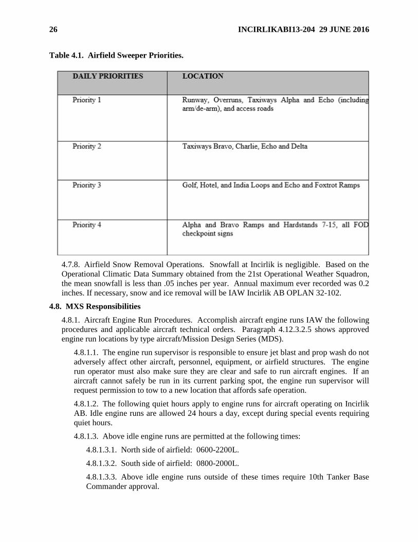
4.7.7. Sweeper Operations. The sweeper will manage the Airfield Sweeper Priorities as
shown in Table 4.1. In addition, the Sweeper will check in at AM daily for any additional
priorities. AM may alter priorities as needed to meet mission requirements. Note: Sweepers
will remain on call for additional/emergency priority areas.
26 INCIRLIKABI13-204 29 JUNE 2016
Table 4.1. Airfield Sweeper Priorities.
4.7.8. Airfield Snow Removal Operations. Snowfall at Incirlik is negligible. Based on the
Operational Climatic Data Summary obtained from the 21st Operational Weather Squadron,
the mean snowfall is less than .05 inches per year. Annual maximum ever recorded was 0.2
inches. If necessary, snow and ice removal will be IAW Incirlik AB OPLAN 32-102.
4.8. MXS Responsibilities
4.8.1. Aircraft Engine Run Procedures. Accomplish aircraft engine runs IAW the following
procedures and applicable aircraft technical orders. Paragraph 4.12.3.2.5 shows approved
engine run locations by type aircraft/Mission Design Series (MDS).
4.8.1.1. The engine run supervisor is responsible to ensure jet blast and prop wash do not
adversely affect other aircraft, personnel, equipment, or airfield structures. The engine
run operator must also make sure they are clear and safe to run aircraft engines. If an
aircraft cannot safely be run in its current parking spot, the engine run supervisor will
request permission to tow to a new location that affords safe operation.
4.8.1.2. The following quiet hours apply to engine runs for aircraft operating on Incirlik
AB. Idle engine runs are allowed 24 hours a day, except during special events requiring
quiet hours.
4.8.1.3. Above idle engine runs are permitted at the following times:
4.8.1.3.1. North side of airfield: 0600-2200L.
4.8.1.3.2. South side of airfield: 0800-2000L.
4.8.1.3.3. Above idle engine runs outside of these times require 10th Tanker Base
Commander approval.
INCIRLIKABI13-204 29 JUNE 2016 27
4.8.2. All aircraft shall be parked in designated parking spots with nose tires on marked
blocks, with the exception of Echo and Foxtrot ramps which do not have marked blocks.
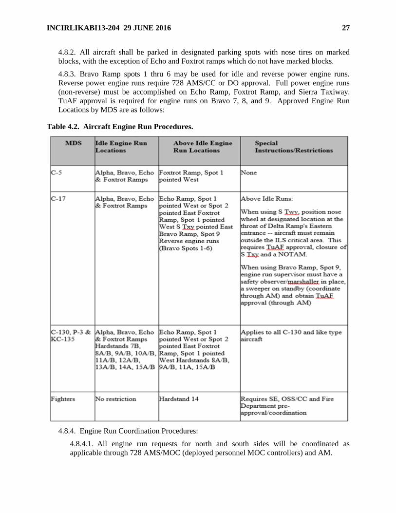
4.8.3. Bravo Ramp spots 1 thru 6 may be used for idle and reverse power engine runs.
Reverse power engine runs require 728 AMS/CC or DO approval. Full power engine runs
(non-reverse) must be accomplished on Echo Ramp, Foxtrot Ramp, and Sierra Taxiway.
TuAF approval is required for engine runs on Bravo 7, 8, and 9. Approved Engine Run
Locations by MDS are as follows:
Table 4.2. Aircraft Engine Run Procedures.
4.8.4. Engine Run Coordination Procedures:
4.8.4.1. All engine run requests for north and south sides will be coordinated as
applicable through 728 AMS/MOC (deployed personnel MOC controllers) and AM.

28 INCIRLIKABI13-204 29 JUNE 2016
4.8.4.2. Coordinate transient aircraft engine run requests (other than USAF C-5, C-17,
and deployed KC-135) through TA who will coordinate with AM and Security Forces
Squadron (SFS) for clearance.
4.8.4.3. All engine runs during quiet hours must be coordinated through 728 AMS/MOC,
39 MXS/MOC, the Airfield Manager (or designated representative), and the 39 OSS/CC
or DO. The Airfield Manager (or designated representative) will coordinate with
AOF/CC or designated representative for TuAF approval. Upon receiving engine run
approval, AM will notify the user, Tower, and SFS. Above idle engine run requests
during quiet hours must meet the following criteria prior to being considered:
4.8.4.3.1. Aircraft is on the flying schedule.
4.8.4.3.2. No spare aircraft available.
4.8.4.3.3. Projected inclement weather or unfavorable winds preventing engine
operations during the normal ops period.
4.8.4.3.4. Manpower constraints during the scheduled launch/recovery window.
4.8.4.3.5. Nature of engine run; troubleshooting vs. operational checks following
maintenance (i.e. troubleshooting to expedite repair/requisition parts vs. operation
checks for repairs highly likely to correct Non-Mission Capable (NMC) condition
based on past experience).
4.8.4.3.6. Number of NMC aircraft vs. projected flying schedule.
4.8.4.4. Engine run operators will contact Tower personnel on Ground Control frequency
and monitor the frequency throughout the engine run operation. The following
information will be relayed to Tower personnel: Aircraft type, tail number, parking
location, power setting, and time required. Notify Tower personnel upon engine run
termination.
4.8.4.5. Engine runs will not be accomplished without proper clearance.
4.8.4.6. Upon notification of a weather watch or a weather warning for lightning within 5
NM, immediately terminate ground engine operations.
4.8.5. Aircraft Taxiing/Towing Procedures.
4.8.5.1. For safety and anti-theft/hijack procedures, all taxiing/towing aircraft must
maintain obtain permission from Ground Control before towing. Wide body aircraft with
wingspans equal to or greater than a B-747 (e.g. C-5, A-380, AN-124) should avoid using
outboard engines for thrust to the maximum extent possible to minimize FOD.
4.8.5.2. All tow operators will coordinate tows and follow the established procedures.
For deployed units, tow operators will coordinate with their deployed MOC. 728 AMS
MOC is responsible for AMC C-5 and C-17 aircraft. Towing of AMC commercial
contract aircraft will be coordinated with the contractor liaison. TA will support all other
tow operations within the limits of their qualifications with a tow driver and wing
walkers, if available; the brake rider and tow super responsibilities reside with the aircrew
and flying crew chief/maintenance recovery team. In the event the aircraft is damaged or
disabled, the Incident Commander will coordinate with TA or deployed Crash, Damaged,
Disabled Aircraft Recovery (CDDAR) personnel on aircraft removal from the runway.

INCIRLIKABI13-204 29 JUNE 2016 29
39th MXS personnel are not tow super or brake rider qualified on the C-130, C-12 or C-
21. 39 MXS will tow C-130, C-12, and C-21 aircraft if a tow a tow bar and additional
personnel are provided by the aircrew to perform those functions.
4.8.5.3. The appropriate MOC will coordinate all tow operations with AM. Information
will include: type aircraft, parking location, destination and tail number.
4.8.5.4. AM will pass aircraft information to the Tower.
4.8.5.5. Tow operators will:
4.8.5.5.1. Coordinate and obtain tow approval from Tower by establishing direct
radio contact with Tower via Ramp Net prior to moving the aircraft.
4.8.5.5.2. Re-state callsign, type aircraft and tail number, tow route, and destination.
Maintain radio contact with Tower on the Ramp Net or Ground Control frequency
throughout the operation. Note: Final authority to postpone or discontinue towing
operations rests with Tower based on aircraft ground movements, coordination, anti-
theft/hijack procedures, or safety.
4.8.6. Taxi Restrictions. When a C-5 or B-747 is parked on Alpha Ramp, only C-17 and
smaller aircraft are allowed to be towed or taxi on taxiway Sierra adjacent to Alpha Ramp
unless approved waiver is on file. Hardstand 10, 11, and 13 will be limited to KC-135 or
smaller aircraft due inadequate wingtip clearance or permissible deviation requirements.
Two KC-135s can park on hardstands 7, 10, 11, 12, 14 and 15, but will require wing-walkers
due to the reduced wingtip clearance.
4.8.7. Aircraft Jacking Procedures. The following procedures must be adhered to regarding
aircraft jacking:
4.8.7.1. Notify AM of the aircraft type, gross weight, tail number, apron, and spot
number. For aprons other than Bravo Apron (Spots 1-6), the location and duration must
be coordinated in advance and approved by AM.
4.8.7.2. Unless a weight waiver is granted, the aircraft gross weight must not exceed, by
aircraft group index (AGI) and weight or by aircraft classification number (ACN) to
pavement classification number (PCN) comparison, the maximum load for the apron and
pavement area.
4.8.7.3. All aircraft specific technical orders, safety conditions, and precautions must be
adhered to.
4.8.7.4. When possible, isolate jacked aircraft by parking location, roped cordon, or
signage advisory.
4.9. Aircraft Parking Plan. Aircraft parking at Incirlik will be assigned by mutual agreement
of the 39 OSS/CC and the Turkish Operations Group Commander. Subject to their further
direction and guidance, USAF has operational control of Alpha ramp, Echo ramp, Foxtrot ramp
and Bravo ramp spots 1-6 (which can accommodate all strategic airlift) as well as Hardstands 7-
16 and 20 (which can accommodate up to KC-135 sized aircraft). TuAF has operational control
of Victor Loop, Charlie ramp, Delta ramp and Bravo ramp spots 7-9.
4.9.1. AM is the airfield parking authority and must be coordinated with by applicable
agencies in the development of all short/long-term aircraft parking plans including for

30 INCIRLIKABI13-204 29 JUNE 2016
distinguished visitors, contingencies, exercises, static displays, air shows and other special
airfield projects. They will assist in the development of areas designated for loading,
unloading, arming and de-arming of aircraft with hazardous cargo or live armament.
4.9.2. Department of Defense Flight Information Publication (FLIP), Area Planning 2 and 39
OSS AM OI 13-204V1, contain updated master airfield wingspan and weight restrictions.
Ramp space is as follows:
4.9.2.1. Alpha Ramp can accommodate up to two C-5 aircraft under normal operations
and can surge to three with approved waiver. If parking C-5 on A1 and A5, then A3 may
be restricted to C-17 or smaller. A2 and A4 may become unusable. Note: Non-standard
parking will be approved by the Airfield Manager. Parking C-5 on A3 will require AM
approval.
4.9.2.2. Bravo Ramp is designed for C-17 aircraft but can accommodate transient KC-
135s. C-130 aircraft may be parked on parking spots B1 and B4 only.
4.9.2.3. Charlie Ramp 1,557 ft x 309 ft.
4.9.2.4. Delta Ramp 720 ft x 270 ft.
4.9.2.5. Echo Ramp 718 ft x 273 ft.
4.9.2.6. Foxtrot Ramp 718 ft x 274 ft
4.10. Pantograph Refueling. Hardstands 7 and 11, Alpha, Delta, Echo and Foxtrot Ramps are
equipped with aircraft refueling pantographs. All Protective Aircraft Shelters (PAS) are
equipped with pantographs with the exception of G65, G68, G71-G75, G81, H1-H3, H5, H6, H8,
I1, I2, I4, and I7.
4.11. Airfield Conditions, Hazards, Inspections, and Checks.
4.11.1. AM is responsible for forwarding all pertinent airfield condition information that
could constitute an aircraft safety hazard to Tower, RAPCON, Command Post, and Flight
Safety. Personnel operating on the airfield should report any observed safety hazards to AM.
4.11.2. AM is responsible for accomplishing airfield inspections and checks IAW AFI 13-
204V3. Airfield inspections and checks are accomplished to identify obstructions or
conditions that are hazardous to aircraft operations. Conditions checked will include, but are
not limited to, construction areas, RSCs, obstruction lights, airfield lighting, wildlife/bird
watch condition, grass mowing, standing water, and FOD. AM will relay all pertinent
information and any changes to Tower, RAPCON, Command Post, and Flight Safety.
4.11.3. The Airfield Manager will conduct quarterly joint airfield inspections IAW AFI 13-
204V3. Attendance by the following agencies is mandatory: OSA/AOF, Tower Chief
Controller, TERPS LNO, 39 ABW/SE, CE, and SFS.
4.11.4. Tower shall notify all aircraft of airfield conditions prior to taxi or the issuance of
landing clearance, with the exception of aircraft switching from RAPCON. Tower will
notify RAPCON and AM of any airfield conditions or discrepancies not previously reported.
4.11.5. RAPCON shall notify all aircraft of airfield conditions on initial contact or prior to
relaying landing clearance.
INCIRLIKABI13-204 29 JUNE 2016 31
4.12. Runway Surface Condition (RSC) and Runway Condition Reading (RCR).
4.12.1. RSC. AM is responsible for runway checks during inclement weather or rapidly
deteriorating weather (rain showers in the vicinity or thunderstorms within 10 NM). Checks
are required to determine effects of weather on the runway surface so accurate advisories
may be relayed to aircrews and increased separation minima may be applied between aircraft
when necessary. The RSC will be reported to the nearest 1/10 of an inch according to T.O.
33-1-23, Equipment and Procedures for Obtaining Runway Condition Readings. Surface
conditions will be identified as “Dry” or “Wet.” NOTAM is required if surface is wet.
4.12.2. RCR. The runway is grooved to facilitate the dissipation of water from the surface
and icing/snow is rare at Incirlik AB, therefore AM is not required to maintain calibration
equipment to perform RCR evaluations.
4.13. Weather Procedures.
4.13.1. The Weather Flight (39 OSS/OSW) is responsible for disseminating weather
information to ATC services. Weather information is automatically fed to the Airfield
Automation System (AFAS) from the weather distribution system. In the event the AFAS is
out of service, Weather personnel will pass on the current weather to Tower and RAPCON.
The Tower updates the ATIS whenever a new observation or change in airfield status is
received then forwards the new ATIS identifier to RAPCON in addition to making a blanket
broadcast over all tower frequencies.
4.13.2. Weather warnings (WW) and weather advisories (WA) are also passed via the
AFAS. Weather observers shall contact ATC facilities with WWs or WAs when the AFAS
is out of service.
4.13.3. Incirlik participates in the Cooperative Weather Watch program as outlined in IABI
15-101, Weather Augmentation Operations. 39 OSS/OSW ensures Tower personnel receive
limited weather observation and visibility training and certification.
4.13.4. Lightning response procedures will be IAW 39 ABW IEMP 10-2, Installation
Emergency Management Plan.
4.14. Bird and Wildlife Aircraft Strike Hazard (BASH) Procedures. Specific
responsibilities and guidelines for tasked organizations are outlined in Incirlik ABI 91-212,
Bird/Wildlife Aircraft Strike Hazard (BASH) Management Techniques. All actions, to include
Bird Watch Conditions, will be IAW 39 ABW PLAN 91-212. 39 ABW Safety is the OPR for
the local BASH program.
4.15. Flight Information Publication (FLIP) Accounts. Each flying unit will maintain an
individual FLIP account.
4.15.1. The NCOIC, AM Operations (NAMO) will appoint a primary and alternate FLIP
manager to maintain FLIPs for required base support functions IAW the National Geospatial
Intelligence Agency catalog.
4.15.1.1. NAMO is the OPR for FLIP accounts.
4.15.1.2. NAMO is the OPR for NOTAM action for FLIP non-procedural change
requests.
32 INCIRLIKABI13-204 29 JUNE 2016
4.16. Wear of Hats and Airfield Smoking Procedures.
4.16.1. Wear of Hats. Flight hats, ABU caps, or other head gear not specifically required for
aircraft ground operations will not be worn on the airfield, aircraft parking ramps, arming or
de-arming areas, or anywhere near aircraft running engines. The only exceptions are for
military protocol (arrival or departure of dignitaries or DVs) or Security Forces (SFS). SFS
will remove and secure their headgear anytime an aircraft is running engines within 200 ft of
the SFS vehicle or guard post. If SFS are wearing Kevlar Helmets, the chinstraps will be
secured. During inclement weather, hoods firmly attached to a coat/jacket, cold weather
hats/woolen caps may be worn. Hats with metal snaps or fasteners will not be worn.
Personnel regularly working on the airfield should use sewn on cloth rank.
4.16.2. Smoking Procedures. Smoking on the airfield is only permitted at the designated
locations IAW with 39 ABW policy.
4.17. Airfield Photography and Videography. Airfield Photography and videography must be
requested through the 39 ABW, Public Affairs office (39 ABW/PA) at 676-6060. 39 ABW/PA
will coordinate requests for photography and videography with the host nation.
4.18. Custodial Control of ATC Tape Recordings. IAW AFI 13-204V3 the AOF/CC is the
custodian for tape recordings in USAF ATC facilities and serves as approval/release authority
for all requests related to review of ATC tapes. Records will be maintained IAW AFI 13-204V3,
USAFESUP. Any request for review and copy of tapes by the TuAF will be routed through the
TuAF Base Operations Commander to the AOF/CC for coordination and approval.
4.19. Exercise Coordination Procedures.
4.19.1. All exercises involving use of the airfield or affecting ATC operations must be
coordinated through the AOF/CC at least 48 hours in advance.
4.19.2. Tower and RAPCON Watch Supervisors have the authority to determine the extent
of facility participation once an exercise begins. Watch Supervisors may terminate their
facility’s participation if safety of flight will be jeopardized. Under such instances, the
Watch Supervisor will immediately notify Command Post and the appropriate ATC staff
members.
4.19.3. Any agency (Command Post, TA, Fire Department, Security Forces, etc.) that
identifies a need to terminate an exercise due to a real-world contingency (emergency, safety
hazard, etc.) shall immediately notify Tower. Tower will broadcast the following message
over the PCAS and all appropriate frequencies: “This is Tower, LIFESAVER, LIFESAVER,
LIFESAVER (reason and approving authority).” Tower will notify RAPCON who will, in
turn, advise airborne aircraft. Note: During local exercises, the lifesaver call should be
substituted with “Terminate, Terminate, Terminate.”
4.20. Quiet Hours for Special Events. Requests for quiet hours for ceremonies such as Change
of Commands or distinguished visitor briefings shall be forwarded, in writing, to 39 OSS/DO for
processing/coordination at least two weeks prior to the requested date. The request is then
forwarded to 39 ABW/CV for coordination with and approval from the TuAF. Note: Quiet
hours, as used in this section, include take-offs, landings and overflights but does not exempt
emergency aircraft handling and TuAF scramble missions. Once approved, AM will issue the
appropriate NOTAM.

INCIRLIKABI13-204 29 JUNE 2016 33
4.21. Miscellaneous Procedures. The following procedures are not normally applied at
Incirlik AB:
4.21.1. Surety Operations. Surety operations occur primarily in Hotel and India loops and at
times encompass Taxiway November. Aircraft parked in the vicinity of a Real World Surety
operation may be affected. ATO sorties may be delayed or cancelled.
4.21.1.1. Coordination for Surety mission training occurs well in advance and should not
adversely affect aircraft operations. The 39 SFS is the POC for all Surety related
operations.
4.21.2. Parachute Drop Operations. Paradrop procedures are not typically used, however the
capability exists. Paradrop procedures will be IAW locally drafted LOA between Airfield
Operations and affected flying units. Contact 39 OSS/OSA (DSN 676-6186) to coordinate
paradrop activities.
4.21.3. Night Vision Device (NVD) Operations. NVD aircraft operations are not authorized
at Incirlik AB, Turkey.
4.21.4. Hot Pit Refueling. Incirlik AB does not have a designated hot pit refueling area. Hot
pit refueling will be coordinated through AM on a case by case basis. Procedures will be
IAW applicable units’ Technical Orders and approved by the 39 OSS/CC.
4.21.5. Remote Control (RC)/Model Aircraft operations. RC aircraft are defined as model
aircraft flown strictly for hobby or recreational use. RC Aircraft activities are prohibited on
or immediately around the airfield. All RC operations will be IAW FAA AC 91-57A and 39
ABW policy.
4.21.6. Exceptions to policy will be at the discretion of the 39 OSS/CC.
4.22. Waivers to Airfield and Airspace Criteria. Waivers to Airfield/Airspace Criteria must
be coordinated through 39 OSS/OSA for the appropriate level of approval. Current waivers are
on file with the Airfield Manager (39 OSS/OSAB). Contact the Airfield Manager for details at
DSN 676-8511/6156.

34 INCIRLIKABI13-204 29 JUNE 2016
Chapter 5
AIR TRAFFIC CONTROL AND LANDING SYSTEMS (ATCALS)
5.1. Airfield/ATCALS Operational Status. Incirlik RAPCON is the primary NOTAM
monitoring facility for ATCALS issues. AM is the focal point for all airfield issues, and is
responsible for disseminating all NOTAM information. The ATCALS section Chief will
coordinate with either the RAPCON Chief Controller/Watch Supervisor or the Tower Chief
Controller/Watch Supervisor as appropriate to coordinate scheduled ATCALS outages. The
ATCALS section Chief will coordinate with AM for all runway/taxiway closures. ATCALS,
RAPCON, Tower, and AM will coordinate all status changes/requests with the AOF/CC or
designated representative.
5.1.1. Preventive Maintenance Inspections (PMIs). No-NOTAM PMI times when the
existing or forecasted weather is 3,000 ft AGL or greater ceiling and 8,000 meters or better
visibility are as follows:
Table 5.1. Airfield/ATCALS Operational Status.
5.2. Requests for Unscheduled ATCALS Downtimes.
5.2.1. ATCALS personnel encountering difficulties during scheduled PMIs will contact the
RAPCON Chief Controller/Watch Supervisor and provide reason for delay and request an
extension, with impact if not approved.
5.2.2. During normal duty hours, Monday through Friday, ATCALS personnel will contact
the RAPCON Chief Controller/Watch Supervisor to extend ATCALS downtime beyond the
scheduled PMI. Specify the requested time, alternate times (if known), reason for the request
and impact if work is not accomplished. RAPCON will coordinate with the AOF/CC.
5.2.3. The AOF/CC or designated representative will coordinate all maintenance requests
with RAPCON, Tower, TuAF ATC, and the 39 OSS/CC.
5.2.4. After normal duty hours, Monday through Friday and on weekends, ATCALS
personnel will contact the RAPCON Watch Supervisor and furnish the required information
from para
5.2.4.1. If an unscheduled equipment malfunction/outage occurs outside of normal duty
hours, the standby technicains will respond no later than 30 minutes after notification.

INCIRLIKABI13-204 29 JUNE 2016 35
Technicians will respond within 15 minutes upon notification of RAPCON evacuation to
Bldg. 682, to provide Alternate RAPCON stand-up/stand-down assistance.
5.2.5. The RAPCON Watch Supervisor will evaluate the impact on current and projected
traffic by coordinating with TuAF ATC and Tower, considering such factors as
inbound/outbound traffic, weather, etc. The Watch Supervisor will either disapprove the
request (based on impact), or coordinate with the AOF/CC for 39 OSS/CC approval of the
ATCALS downtime request.
5.2.6. If approved, the Watch Supervisor will notify ATCALS, TuAF ATC, Tower and AM
(for NOTAM action as required). Watch Supervisors will not release more than one
ATCALS asset at a time without prior approval of the 39 OSS/CC.
5.3. NOTAM Requirements for ATCALS Equipment.
5.3.1. The RAPCON will:
5.3.1.1. Act as the reporting center to AM for all outages and malfunctions of
USAF/TuAF operated and maintained ATC facilities and ATCALS. Each report will
contain a reason for the outage and an estimated time of return to operational status if
known.
5.3.1.2. Verify current NOTAMs daily with AM or via the internet and notify AM when
equipment previously NOTAMed out returns to service.
5.3.2. AM will notify RAPCON, Tower, Command Post, TuAF, AMCC, FD, SF, Unit
ADPMs and any other deployed agencies of all new NOTAMs.
5.3.3. Command Post will notify Squadron Operations Centers (SOCs) of all new ATCALS
NOTAMs.
5.4. TACAN Out Procedures.
5.4.1. When the Incirlik TACAN (DAN) is taken off the air or is out of service for any
reason, HI/LOW TACAN Runway 05/23 are not usable. Primary approaches into Incirlik
will be GPS or ILS.
5.4.2. When on an ILS approach, radar will be used by ATC to establish the final approach
fix (FAF). ATC will provide an “over the FAF” advisory: “PASSING FINAL APPROACH
FIX” and provide alternate missed approach instructions.
5.5. Digital Airport Surveillance Radar (DASR) Wind Limitations. The RAPCON will
notify ATCALS to turn the DASR antenna off (turning the antenna off will allow it to freewheel)
when the wind velocity reaches or is forecast to reach 65 knots.
5.6. ATCALS Review Board. The ATCALS Review Board’s purpose is to discuss and make
recommendations concerning various ATCALS programs and projects and issues affecting air
traffic control related equipment.
5.6.1. The board will convene quarterly and may be combined with the quarterly AOB.
Board Members (participation is mandatory):
5.6.1.1. AOF/CC
5.6.1.2. ATCALS System Manager (39 OSS/OSAM)

36 INCIRLIKABI13-204 29 JUNE 2016
5.6.1.3. Airfield Systems Maintenance (39 OSS/OSAM)
5.6.1.4. Radar Maintenance (39 OSS/OSAM)
5.6.1.5. Radio Maintenance (39 CS)
5.6.1.6. Civil Engineering Plans
5.6.1.7. Airfield Lighting (39 CES)
5.6.1.8. Plans and Programs (39 CS)
5.6.1.9. AM
5.6.1.10. ATC Facility Managers
5.6.2. Agenda Items: All items will be IAW AFI 13-204 USAFE Sup1.
5.6.3. ATCALS review board minutes will be distributed IAW AFI 13-204 USAFE Sup1.
5.7. ATCALS Backup Power.
5.7.1. 39th Civil Engineering Squadron Power Production shall:
5.7.1.1. Physically inspect all generators at ATCALS facilities twice a month for fuel,
water, and oil. Correct any discrepancies immediately and inform appropriate facility
manager of maintenance performing or pending.
5.7.1.2. Once each month, after 24 hours prior coordination and approval from each
facility Chief Controller, load test each ATCALS generator by shutting off primary
commercial power and, without any special adjustments to the auxiliary power system,
run the generator for a minimum of one hour under full-load.
5.7.1.3. Obtain approval from the Tower Watch Supervisor and RAPCON Watch
Supervisor prior to any power change to the Control Tower and RAPCON generator
respectively.
5.7.1.4. Dispatch qualified personnel if Tower or RAPCON generator fails. Response
time will be within 15 minutes after notification.
5.8. Civilian Aircraft Operations and Use of USAF ATCALS. Civil aircraft may be provided
radar service, but they are not permitted to make any approaches to the Incirlik AB runway.
Department of Defense (DoD) or NATO contracted aircraft will be afforded the same service as
DoD and NATO military aircraft.

INCIRLIKABI13-204 29 JUNE 2016 37
Chapter 6
TERMINAL AREA PROCEDURES
6.1. Local Aircraft Priorities. ATC services will be prioritized IAW Doc 4444, LOAs Related
to the Conduct of Air Traffic Services within the Adana Military Terminal Control Area
(MTCA) and Standard Operating Procedures (SOP). Incirlik Air Base Aircraft Priorities are as
follows:
6.1.1. Emergency Aircraft Arrival
6.1.2. Actual MEDEVAC Missions
6.1.3. Actual (real-world) Scramble Departure/Arrival0
6.1.4. Actual Search and Rescue (SAR) Missions
6.1.5. All Air Tasking Order (ATO)
6.1.6. VIP Arrival/Departure
6.1.7. Controlled Departure Time
6.1.8. IFR Arrivals and Departures
6.1.9. Opposite Direction Arrivals/Departures
6.1.10. Training Missions
6.2. Runway Selection Procedures. Runway 23 is designated as the calm wind runway. The
calm wind runway will be used to the maximum extent possible when the wind is less than or
equal to 5 knots. USAF and TuAF Tower Watch Supervisors or Senior Controllers are equally
responsible for selecting the runway in use, but the TuAF is the final decision authority.
6.2.1. Tower will notify RAPCON, AM, Barrier Maintenance, Fire Department, and the on-
duty SOF, prior to starting runway change procedures. AM is responsible for relaying
runway change information to other base agencies.
6.2.2. The Tower will notify RAPCON, AM, Weather and Command Post upon completion
of the runway change.
6.3. Opening/Closing and Suspending/Resuming Runway Operations.
6.3.1. Opening/Closing the Runway. AM is the opening and closing authority for the
runway.
6.3.2. AM shall open the runway after any runway closure, prior to any flying operations on
the airfield. AM will ensure all proper checks and notifications are done IAW AFI 13-204V3
and local checklists.
6.3.3. AM has the authority to close the runway when:
6.3.3.1. Construction, airfield repair or snow removal operations on or near the runway.
6.3.3.2. There is an aircraft mishap on the airfield.
38 INCIRLIKABI13-204 29 JUNE 2016
6.3.3.3. Directed by the Crisis Action Team, 39 ABW/CC, 39 OSS/CC, AOF/CC,
Airfield Manager or designated representative.
6.3.3.4. There is any unsafe condition that will affect runway operations, typically for an
extended period of time.
6.3.4. Suspending/Resuming Runway Operations.
6.3.4.1. AM/Tower Watch Supervisor shall suspend runway operations when:
6.3.4.1.1. An emergency aircraft lands.
6.3.4.1.2. A disabled aircraft is on or near the runway.
6.3.4.1.3. There is a possibility of debris on the runway.
6.3.4.1.4. Directed by the Crisis Action Team, 39 ABW/CC, 39 OSS/CC, AOF/CC,
Airfield Manager/Tower Watch Supervisor or designated representative.
6.3.4.1.5. In AM or Tower Watch Supervisor’s opinion, safety of flight is
jeopardized.
6.3.4.2. If runway operations are suspended by an agency other than the Tower, the
agency suspending runway operations shall notify Tower of the reason.
6.3.4.3. Tower shall not resume normal operations until the Airfield Manager or
designated representative has determined that the runway is safe and operations should be
resumed. All runway checks will be IAW AFI 13-204V3.
6.4. Automatic Terminal Information Service (ATIS). The ATIS operates 24 hours a day, 7
days a week and contains information IAW ATC directives. Aircraft shall notify ATC on initial
contact of which ATIS code they received.
6.5. Intersection Departures (Attachment 2). Intersection departures are authorized as
indicated below. Distances depict usable runway length from the intersection to the end of the
runway.
6.5.1. Departing Runway 05: Taxiway B - 9,000 ft remaining.
6.5.2. Departing Runway 05: Taxiway C - 7,000 ft remaining.
6.5.3. Departing Runway 23: Taxiway D - 8,000 ft remaining.
6.6. Opposite Direction Operations. Opposite direction runway operations may be available
when dictated by an operational need and if traffic conditions permit. Request an opposite
direction arrival/departure as soon as possible to allow for ATC coordination. Aircraft can
expect up to a 30 minute delay for a barrier configuration change. If opposite direction departure
is authorized, departure over a raised approach end barrier is prohibited. Departure will occur in
front of the barrier. Aircraft may taxi past barrier then depart or depart from an intersection.
(See para 6.5 for feet available)
6.7. Noise Abatement Procedures. Do not overfly the city of Adana below 3,300 ft MSL. Do
not fly within 5 nautical miles (NM) laterally and below 5,300 ft MSL over the city of Mersin.
Do not fly circling approaches below 1,500 ft MSL south of Runway 05/23 during Visual
Meteorological Conditions (VMC) for noise abatement over base housing and Incirlik village.
Refer to the Enroute Supplement for VFR pattern availability.

INCIRLIKABI13-204 29 JUNE 2016 39
6.8. VFR Operations. All aircraft must contact Incirlik Approach before entering the Adana
MTCA (50 NM circle). Unless issued an IFR clearance to include a clearance limit, e.g.
destination airport or other fix, all aircraft are considered VFR and will conduct operations in
VMC. Aircrews unable to maintain VMC will immediately advise ATC. All VFR aircraft
within the MTCA will be on an ATC frequency and will be provided air traffic services, which
includes traffic information, sequencing, vectoring and altitude assignment (when necessary).
All aircraft will receive this service unless the pilot specifically states VFR radar service is not
desired. Aircraft declining radar service are still required to monitor the ATC frequency, within
ATC radar and radio coverage, and report moving (entry and exit) from one working area to
another. Radar service is automatically terminated when VFR aircraft are instructed to contact
Tower.
6.9. VFR Weather Minima. VFR flight within the local area is authorized from 30 minutes
before sunrise until 30 minutes after sunset, unless otherwise coordinated with TuAF officials or
in applicable LOP. The ceiling and visibility must be at or above 1,500 ft AGL and 5,000
meters.
6.10. VFR Entry Points. USAF and TuAF ATC use three VFR reporting points: Eagle, Tiger,
and Falcon. (Attachment 4). Note: The entry altitude is 2,500 ft MSL for initial and 2,000 ft
MSL for straight-ins. A 2,800 ft AGL ceiling and visibility of 5,000 meters are minimum
weather requirements for VFR entry points. IFR clearance is automatically cancelled upon
reaching the VFR entry point.
6.10.1. Runway 05. Maintain VFR and proceed to EAGLE (DAN 210/09). Depart EAGLE
to intercept initial/final.
6.10.1.1. Initial: Cross EAGLE at 2,500 ft MSL and descend to 2,000 ft MSL at 5 NM
initial (7 DME).
6.10.1.2. Straight-In: Cross EAGLE at 2,000 ft MSL and descend to 1,500 ft MSL at 5
NM (7 DME).
6.10.2. Runway 23. Maintain VFR and proceed to FALCON (DAN 072/12) or TIGER
(DAN 038/12). Depart FALCON and TIGER to intercept initial/final.
6.10.2.1. Initial: Cross FALCON/TIGER, at 2,500 ft MSL and descend to 2,000 ft MSL
at 5 NM initial (5 DME).
6.10.2.2. Straight-In: Cross FALCON/TIGER, at 2,000 ft MSL and descend to 1,500 ft
MSL by 5 NM (5 DME).
6.11. VFR Traffic Patterns. Prior coordination with Tower is required if variations to the
following published traffic pattern altitudes are required.
6.11.1. Conventional Rectangular Traffic Pattern, Non-Fighter Type Aircraft (Attachment
4). Pattern altitude is 1,500 ft MSL; Light Aircraft/Helo Pattern altitude is 1,000 ft MSL.
Pattern is to the south; left downwind Runway 23 / right downwind Runway 05. A 1,800 ft
AGL ceiling and visibility of 5,000 meters are minimum weather requirements. The Tower
Watch Supervisor determines whether the pattern is usable. Aircraft going missed approach
or sent around by Tower will be re-sequenced in the radar pattern. If weather is VFR and the
pilot requests, aircraft may enter the VFR closed traffic pattern after coordinating with
Tower.

40 INCIRLIKABI13-204 29 JUNE 2016
6.11.2. Overhead Pattern (Attachment 4). The overhead pattern altitude is 2,000 ft MSL,
and is available Monday through Friday 0600L- sunset, except Turkish holidays. South
break is standard for all aircraft; left break Runway 23 / right break Runway 05. A 2,300 ft
AGL ceiling and visibility of 5,000 meters are minimum weather requirements. The Tower
Watch Supervisor determines whether the pattern is usable.
6.11.3. Tactical Initial.
6.11.3.1. Tactical initial may be requested by pilots upon VFR entry. All reporting
points, altitudes, and weather requirements for the overhead remain unchanged.
6.11.3.2. Pilots will report Tactical Initial at 5 DME.
6.11.3.3. Pilots will line up to avoid overflight north of the runway at all times.
6.11.4. Closed Traffic Pattern (Attachment 4). Fighter closed traffic pattern altitude is 2,000
ft MSL. A 2,300 ft AGL ceiling and visibility of 5,000 meters are minimum weather
requirements. Non- Fighter aircraft closed traffic pattern is the same as the conventional
rectangular pattern. The Tower Watch Supervisor ultimately makes the decision as to
whether the patterns are usable. Closed traffic is upon request and must be coordinated with
and approved by the TuAF controller on duty.
6.11.5. Pattern Re-entry. Re-entry is from the south for both runways to avoid overflying
Adana.
6.11.5.1. Straight-ins will climb and maintain 2,000 ft MSL for re-entry.
6.11.5.2. VFR Breakout. Climb to 2,500 ft MSL. Upon reaching 2,500 ft MSL turn
south and proceed to the VFR entry point.
6.11.5.3. Go-Around. Do not overfly aircraft on the runway below 500 ft AGL (800 ft
MSL) vertically and 500 ft laterally. Offset to the south if necessary.
6.11.6. Helicopter Patterns. Pattern altitude and direction shall be 1,000ft MSL or as
instructed by Tower.
6.11.7. Simulated/Real SFO Procedures (Attachment 4).
6.11.7.1. TDY/Deployed aircraft may fly straight-in (SI) and overhead SFOs utilizing the
following procedures. Prior to conducting SFOs, a signed Letter of Agreement between
the 39 OSS/CC and TDY/Deployed Squadron/CC must be in place.
6.11.7.2. Pattern Descriptions:
6.11.7.2.1. Overhead SFO: Shall always be flown south of the field.
6.11.7.2.2. SI SFO: May commence at 10NM along the extended runway centerline.
Random SFO entries shall not be conducted (i.e. procedure shall not start at VFR
entry points).
6.11.7.3. Minimum Weather Requirements:
6.11.7.3.1. Ceiling must be at least 1000ft above the highest part of the pattern flown
(for both SI and overhead) and 5 miles visibility.

INCIRLIKABI13-204 29 JUNE 2016 41
6.11.7.3.2. The pilot must maintain VMC throughout the approach. In addition, the
pilot must maintain visual contact with the runway environment throughout the
maneuver.
6.11.7.3.3. SFOs are only authorized between sunrise and sunset.
6.11.7.4. SFO Entry Altitudes:
6.11.7.4.1. High Key or 10 NM (SI): 7,500ft MSL – 9,000ft MSL.
6.11.7.4.2. Low Key: 3,000ft MSL – 5,000ft MSL.
6.11.7.4.3. Pilot must notify Tower of entry altitude.
6.11.7.5. SFO Low Approach Procedures:
6.11.7.5.1. RWY 23/05: Aircraft on the go for an overhead SFO will fly runway
heading until Tower approves a climb to either high key or low key altitude. Climbs
will begin at the departure end of the runway. All climbs will be south of the field
only. Note: ATC may issue alternate instructions when traffic dictates.
6.11.7.6. Pilots will:
6.11.7.6.1. Notify Tower or Approach with current position, SFO request (as soon as
possible for coordination).
6.11.7.6.2. Ensure that all radio calls are made at the correct points to aid Tower in
traffic sequencing. SI SFOs require a radio call to Tower indicating entry point call.
The following radio calls are mandatory for straight in SFOS: 10NM straight in SFO
and 5 NM straight in SFO gear down, low approach. The following calls are
mandatory for overhead SFOs: High Key, Low Key, gear down, low approach.
6.11.7.6.3. Remain vigilant for traffic in and around the overhead SFO maneuvering
area.
6.11.7.6.4. When initiating a traffic breakout, if possible, remain at least 1000ft
above overhead pattern altitude and re-enter at high key or a VFR reporting point.
6.11.7.7. Tower will:
6.11.7.7.1. Approve or disapprove the simulated SFO (and requested entry point)
based on traffic and weather conditions.
6.12. Overhead Pattern Protection. Departures will be instructed to maintain at or below
1,500 ft MSL until departure end, as required to protect the overhead pattern.
6.13. Reduced Same Runway Separation (RSRS).
6.13.1. RSRS is applicable to all non-formation aircraft except as outlined in this
supplement. Note: For the purpose of applying RSRS, formation landing is defined as two
aircraft crossing the threshold at the same time (i.e., Holding-hands). Note: Aircrew or air
traffic controllers may refuse RSRS when safety of flight may be jeopardized. In these cases,
the appropriate separation standards published in FAAO 7110.65, or governing HN
regulation shall be used.
6.13.2. RSRS may be applied to the following:

42 INCIRLIKABI13-204 29 JUNE 2016
6.13.2.1. Full-stop behind a full-stop, low-approach, or touch-and-go.
6.13.2.2. Touch-and-go behind a touch-and-go or low-approach
6.13.2.3. Low-approach behind a low-approach.
6.13.2.4. Low-approach behind a full-stop:
6.13.2.4.1. Fighter/attack aircraft. The succeeding aircraft will offset laterally as to
not overfly the aircraft on the runway.
6.13.2.4.2. The succeeding C-130 must maintain at least 500 feet lateral or vertical
separation when overflying the C-130 on the runway.
6.13.3. RSRS is not authorized when:
6.13.3.1. Either aircraft is an emergency.
6.13.3.2. Either aircraft is a heavy.
6.13.3.3. Either the succeeding or preceding aircraft is cleared for the option or a stop-
and-go. Exception: RSRS is authorized when the succeeding aircraft is cleared for an
option or a stop-and-go behind a low approach.
6.13.3.4. Runway condition braking action is reported as equal to, or less than “POOR”.
6.13.4. Weather must be at or above a 500 ft ceiling and 2,400 meters visibility for nighttime
RSRS operations.
6.13.5. The minimum RSRS authorized will be IAW Tables 6.1 and 6.2:
Table 6.1. RSRS Minimums for Similar Fighter Type Aircraft.
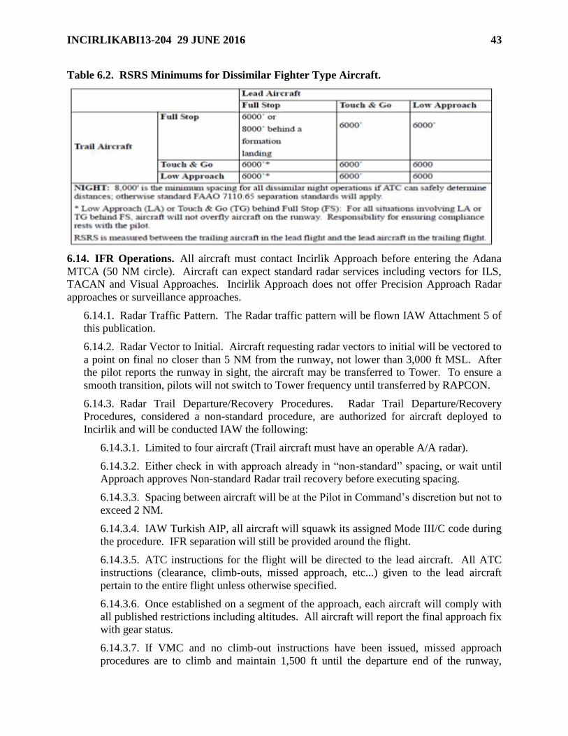
INCIRLIKABI13-204 29 JUNE 2016 43
Table 6.2. RSRS Minimums for Dissimilar Fighter Type Aircraft.
6.14. IFR Operations. All aircraft must contact Incirlik Approach before entering the Adana
MTCA (50 NM circle). Aircraft can expect standard radar services including vectors for ILS,
TACAN and Visual Approaches. Incirlik Approach does not offer Precision Approach Radar
approaches or surveillance approaches.
6.14.1. Radar Traffic Pattern. The Radar traffic pattern will be flown IAW Attachment 5 of
this publication.
6.14.2. Radar Vector to Initial. Aircraft requesting radar vectors to initial will be vectored to
a point on final no closer than 5 NM from the runway, not lower than 3,000 ft MSL. After
the pilot reports the runway in sight, the aircraft may be transferred to Tower. To ensure a
smooth transition, pilots will not switch to Tower frequency until transferred by RAPCON.
6.14.3. Radar Trail Departure/Recovery Procedures. Radar Trail Departure/Recovery
Procedures, considered a non-standard procedure, are authorized for aircraft deployed to
Incirlik and will be conducted IAW the following:
6.14.3.1. Limited to four aircraft (Trail aircraft must have an operable A/A radar).
6.14.3.2. Either check in with approach already in “non-standard” spacing, or wait until
Approach approves Non-standard Radar trail recovery before executing spacing.
6.14.3.3. Spacing between aircraft will be at the Pilot in Command’s discretion but not to
exceed 2 NM.
6.14.3.4. IAW Turkish AIP, all aircraft will squawk its assigned Mode III/C code during
the procedure. IFR separation will still be provided around the flight.
6.14.3.5. ATC instructions for the flight will be directed to the lead aircraft. All ATC
instructions (clearance, climb-outs, missed approach, etc...) given to the lead aircraft
pertain to the entire flight unless otherwise specified.
6.14.3.6. Once established on a segment of the approach, each aircraft will comply with
all published restrictions including altitudes. All aircraft will report the final approach fix
with gear status.
6.14.3.7. If VMC and no climb-out instructions have been issued, missed approach
procedures are to climb and maintain 1,500 ft until the departure end of the runway,
44 INCIRLIKABI13-204 29 JUNE 2016
maintain VMC, and contact tower. If IMC, execute published missed approach
procedures and notify ATC.
6.14.3.8. Aircraft experiencing communication failure will squawk 7600 and continue
with the procedure or approach. ATC will inform the other aircraft in the flight of the
aircraft with lost comm.
6.14.3.9. Aircrews conducting radar-in-trail recoveries are responsible for their own
separation between elements of their flight while on final for full-stop landings.
6.15. Standard Climb-Out Procedures.
6.15.1. Runway 05/23: After completing low approach or touch-and-go, continue runway
heading, cross departure end at or below 1,500 ft MSL (if overhead pattern is in use), climb
to 4,000 ft MSL, contact Incirlik RAPCON on assigned frequency.
6.15.2. Departure procedures are coordinated through Ankara Center. Departures will
normally be instructed to “continue runway heading, climb to (altitude).”
6.16. Go-Around/Breakout/Missed Approach Procedures.
6.16.1. Go-around instructions apply to those aircraft at or inside 6 miles on final approach
below the Minimum Vectoring Altitude (MVA).
6.16.2. Breakout instructions apply to those aircraft outside 6 miles on final approach above
the MVA and will be IAW the Tower, RAPCON, and AM Coordination Letter, which can be
obtained from 39 OSS/OSA.
6.16.3. In the event of a missed approach, execute the published procedures unless otherwise
instructed by ATC.
6.17. Unmanned Aircraft System (UAS)/Remotely Piloted Aircraft (RPA)
Procedures. RPA operations, including starting areas, arresting gear requirements, and lost link
procedures will be conducted IAW the Standard Operating Procedures (SOP) for USAF MQ-1
Predator Unmanned Aerial Vehicle at Incirlik AB.
6.18. Helicopter Operations. Helicopter traffic patterns will be as coordinated with Tower.
Pilots from deployed units may not operate helicopters at any time within Golf, Hotel, and India
Loop areas. Other helicopter operations must comply with minimum distance requirements
between helicopter and obstructions outlined in AFI 11-218. The runway is normally the only
designated arrival/departure point for helicopters. Requests for arrival/departure to/from other
surfaces on the airfield will be handled on an individual basis IAW ATC procedures.
6.19. Multiple Approaches/Pattern Work Procedures.
6.19.1. Closed traffic patterns require approval from Tower. Do not initiate a closed or
crosswind turn prior to departure end of runway unless instructed to do so by Tower.
6.19.2. Low approaches or touch and go’s require approval from Tower.
6.19.3. Pattern work. Pattern work/local approach requests must be submitted to 39
OSS/OSAB’s organizational email at [email protected] NLT 24 hours prior to the
requested date. The AOF/CC or AM will coordinate final approval with TuAF Base
Operations leadership.
INCIRLIKABI13-204 29 JUNE 2016 45
6.20. Functional Check Flights (FCF).
6.20.1. The primary area for FCFs is LTD-13. Entry/exit procedures will be IAW paragraph
3.13. Additional areas may be coordinated as needed.
6.20.2. Coordinate with the Airfield Operations Flight (39 OSS/OSA) NLT 72 hours prior to
the scheduled flight. NLT Thursday if flying on the weekend. The AOF/CC or AOF/DO
will coordinate final approval with TuAF Base Operations leadership.
6.21. Supervisor of Flying (SOF). When implemented, SOF procedures will be IAW with
locally developed LOA between 39 OSS and applicable unit(s).
46 INCIRLIKABI13-204 29 JUNE 2016
Chapter 7
AIRCRAFT REQUIRING SPECIAL HANDLING
7.1. Unusual Maneuvers within the Airport Traffic Area. Unusual maneuvers, other than
those contained in this instruction and other local operating procedures, require 39 OSS/CC or 39
ABW/CC approval. Forward requests through the chain of command.
7.2. Aeromedical/Air Evacuation (AIREVAC) Procedures.
7.2.1. The 39 MDG will notify base operations of any known AIREVAC which will land at
Adana Airport or Incirlik AB when it is tasked
7.2.2. AM shall provide the Tower, Hospital, Fire Department and AMCC with notification
of an inbound AIREVAC aircraft as soon as information is received.
7.2.3. Tower shall notify Fire Department when aircraft is 15 miles from landing.
7.2.4. Fire Department shall provide a fire truck to stand-by during its ground time while
patients remain on the aircraft.
7.2.5. Departing aircraft shall have a fire truck available prior to loading patients until they
take the runway for departure.
7.3. Distinguished Visitor (DV) Notification. Upon receiving a departure message on an
inbound DV, AM will complete their DV Checklist. RAPCON will give AM a 50 NM inbound
call. AM shall contact TA and Command Post who will notify appropriate agencies of this
information as soon as possible. Agencies will practice Operations Security (OPSEC) when
relaying DV information.
7.3.1. AM will notify Tower, RAPCON, Command Post, Protocol, 39 OSS/CC, AMCC, the
Airfield Manager and TA whenever a Prior Permission Request (PPR) for a DV aircraft is
received. Note: If at any time the aircraft commander requests no DV privileges for A6 and
above, the controlling facility shall notify AM.
7.4. Hazardous/Dangerous Cargo.
7.4.1. Foxtrot (primary) and Echo (secondary) Ramps are designated hazardous cargo pads.
Alpha and Bravo Ramps are alternate locations for aircraft that have Net Explosive Weight
1.3 or 1.4 cargo. The intersection of Taxiway November and Taxiway Charlie North is also
sited as a hazardous cargo pad for Close Watch missions however coordination with AM is
required prior to use. AM will coordinate approval with the 39 OSS/CC. Taxiway
November and taxiway Charlie North is authorized to have NET Explosive Weight 1.3 and
1.4.
7.4.2. Parking Aircraft with Explosives or Hazardous Cargo. All gun systems will be kept in
the "safe" condition and aircraft shall be positioned to present the minimum hazard to
personnel and resources in the event of a mishap. Personnel will not stand or park in front of
aircraft with forward firing munitions when power is applied, IAW AFMAN 91-201,
Explosives Safety Standards.

INCIRLIKABI13-204 29 JUNE 2016 47
7.5. Drogue (Drag) Chute Jettison Areas. Taxiways Alpha and Echo are designated as drogue
chute jettison locations. Aircraft will release their chutes on either side of the taxiway as dictated
by the wind direction. Tower may require that aircraft use areas other than designated locations.
TuAF and deployed units are responsible for recovery of their chutes, however if safety of flight
is a concern, Tower will notify AM or TA for drag chute recovery.
7.6. Arm/De-Arm Areas. Taxiways Alpha North and Echo North are authorized as the primary
arm/de-arm areas. (Attachment 2 and Attachment 3)
7.7. ATC Handling of Special Reports. ATC facilities receiving special reports (Lasing, High
Energy Weapons, Communications Instructions for Vital Intelligence Sightings (CIRVIS), Glass
Eye Reports) will immediately forward such information to the Command Post.
7.8. Decontamination (DECON) Procedures. Tower will activate the Primary Crash Alarm
System (PCAS) and direct contaminated aircraft to Echo or Foxtrot Ramp or another site as
determined by AM via coordination with 728 AMS/MOC and/or 39 OSS/CC as required.
7.9. Calculated Take-Off Times (CTOT)/Controlled Departure Time (CDT)/Slot
Times. Certain aircraft are issued or require CTOT/CDT/slot time to accomplish their mission
to comply with ATC enroute flow control timing, rendezvous at an air refueling contact point or
meet range times. When a CTOT/CDT/slot time is issued or required, the following procedures
apply:
7.9.1. The agency who receives information (AM or RAPCON) will promptly notify Tower
of the slot time as received from Eurocontrol in Brussels.Tower will advise the aircraft of
CTOT/slot time as soon as possible.
7.9.2. Aircraft requiring a CDT for mission requirements shall make the request with
Ground Control as soon as possible. Note: Eurocontrol slot times are valid 5-minutes prior
until 10-minutes past the designated time. Aircraft unable to be airborne during this period
will not be allowed to depart until a new slot time, or direct approval from Eurocontrol, has
been received by ATC.
7.10. 30/30 Procedures.
7.10.1. Upon notification of a real world 30/30, to facilitate transit to the north side of the
airfield, Security Forces Squadron (SFS) will coordinate with the Tower Watch Supervisor
for operational control of the runway and taxiways as required. Coordination will occur
before entering any part of the CMA. SFS will advise Tower personnel when movement is
complete and relinquish control. Tower will sterilize the CMA of all aircraft and non SFS
vehicles.
7.10.2. For exercises, all coordination and operations will be IAW 30/30 Operations Letter.
During exercises or emergencies, SFS will coordinate with Tower for operations in any areas
located within the CMA, and will not enter the CMA without Tower approval.
7.11. Radio Out/Lost Communication. Aircraft experiencing radio failure shall proceed as
follows:
7.11.1. Radar Traffic Pattern. If no transmissions are received for 1 minute in the pattern,
attempt contact on guard frequencies and squawk 7600. If no contact, climb to the Minimum
Safe Altitude (MSA), proceed to the initial approach fix for the TACAN, ILS, or GPS

48 INCIRLIKABI13-204 29 JUNE 2016
approach and commence approach. Once established on the approach, reattempt contact with
Tower and remain vigilant for light gun signals.
7.11.2. VFR Traffic Pattern.
7.11.2.1. Fighter aircraft will climb to 3000 ft MSL and proceed to initial. At initial, it
will rock its wings and look for a light gun signal. If the aircraft receives a green light
gun signal the aircraft will break south at midfield to land on the active runway. After
landing the aircraft will exit the runway at Alpha North or Echo North and can expect fire
crews waiting to provide emergency services. Between the hours of Sunset and Sunrise,
enter the rectangular pattern at 2000 ft MSL, flashing navigation/landing lights. Tower
will issue the appropriate light gun signal as the aircraft turns base leg to final.
7.11.2.2. Conventional aircraft will fly the rectangular pattern to the active runway;
rocking wings or at night, flashing navigation/landing lights. Tower will issue the
appropriate light gun signal as the aircraft turns base leg to final.
7.11.3. The 414th ERS shall proceed IAW the SOP for USAF MQ-1 Predator Unmanned
Aerial Vehicle at Incirlik Air Base, Turkey.
JOHN C. WALKER, Colonel, USAF
Commander

INCIRLIKABI13-204 29 JUNE 2016 49
Attachment 1
GLOSSARY OF REFERENCES AND SUPPORTING INFORMATION
References
AFPD 13-2, Air Traffic Control, Airspace, Airfield and Range Management, 7 Aug 2007
AFI 11-202, Volume 3, General Flight Rules, 7 Nov 2014
AFI 11-208, Department of Defense NOTAM System, 3 Jun 2011
AFI 11-218, Aircraft Operations and Movement on the Ground, 28 Oct 2011
AFI 11-255, Volume 3, Integrated Flight Management Responsibilities and Procedures, 8 Mar
2012
AFI 13-204, volumes 1, 2, and 3, Airfield Operations, 1 Sep 2010, Incorporating 2015 changes
USAFEI 13-204 volumes 1 and 2, Airfield Operations, 6 Jan 2016
AFI 91-202, The US Air Force Mishap Prevention Program, 24 Jun 2015
AFMAN 11-226, United States Standard for Terminal Instrument Procedures (TERPS), 31 Dec
2009
AFMAN 33-360, Management of Records, 1 Mar 2013
AFMAN 91-201, Explosives Safety Standards, 12 Jan 2011
Defense Economic Cooperation Agreement (DECA), 29 Mar 1980
Engineering Technical Letter (ETL) 04-02, Standard Airfield Pavement Marking Schemes, 19
Jul 2004
Federal Aviation Administration Order JO 7110.65, Air Traffic Control 11 Feb 2010
International Civil Aviation Organization (ICAO) Doc 4444, Air Traffic Management, 22 Nov
2007
Unified Facilities Criteria (UFC) 3-260-01, Airfield and Heliport Planning and Design, 17 Nov
2008
T.O. 33-1-23, Equipment and Procedures for Obtaining Runway Condition Readings, 30 Nov
2006
T.O. 35E8-2-5-1, Operation and Maintenance Instructions, Aircraft Arresting Systems Model
BAK-12/E32A, Basic 2 Feb 2004, Change 8-12 Jan 2009
Turkish AIPs
IABI 15-101, Weather Augmentation Operations, 5 Sept 2008
39 ABW IEMP 10-2, Installation Emergency Management Plan
39 ABW OPLAN 91-211, Major Mishap Response Plan for Flight, Ground, and Weapons
Mishaps, 30 Apr 2007
50 INCIRLIKABI13-204 29 JUNE 2016
39 ABW PLAN 91-212, Bird/Wildlife Aircraft Strike Hazard (BASH) Reduction Plan, 14 Nov
2008
AM OI 13-204v1, AM Operations
USAFEI 32-1007, Airfield and Heliport Planning and Design
DD Form 1801, DoD International Flight Plan.
Abbreviations and Acronyms
AB—Air Base
ABW—Air Base Wing
ACN—Aircraft Classification Number
AIREVAC—Air Evacuation
AFAS—Airfield Automation System
AGI—Aircraft Group Index
AGL—Above Ground Level
AICUZ—Air Installation Compatible Use Zone
AIP—Aeronautical Information Publication
AMC—Air Mobility Command
AMCC—Air Mobility Control Center
AOB—Airfield Operations Board
AOF—Airfield Operations Flight
AOF/CC—Airfield Operations Flight Commander
ASR—Airport Surveillance Radar
ATC—Air Traffic Control
ATCALS—Air Traffic Control and Landing Systems
ATIS—Automatic Terminal Information Service
BASH—Bird/Wildlife Aircraft Strike Hazard
BAK—Barrier Arresting Kit
CIRVIS—Communications Instructions for Vital Intelligence Sightings
CMA—Controlled Movement Area
CSC—Central Security Control
CTOT—Calculated Take-Off Times
DECA—Defense and Economic Cooperation Agreement
DECON—Decontamination
INCIRLIKABI13-204 29 JUNE 2016 51
DME—Distance Measuring Equipment
DoD—Department of Defense
DV—Distinguished Visitor
ELT—Emergency Locator Transmitter
EOC—Emergency Operations Center
EPU—Emergency Power Unit
ETA—Estimated Time Arrival
FAF—Final Approach Fix
FCF—Functional Check Flight
FL—Flight Level
FLIP—Flight Information Publication
FOD—Foreign Object Damage
FOUO—For Official Use Only
FPCON—Force Protection Condition
GE—Ground Emergency
GPS—Global Positioning System
HATR—Hazardous Air Traffic Report
HIRL—High Intensity Runway lighting
IABI—Incirlik Air Base Instruction
IAW—In Accordance With
IC—Incident Commander
ICAO—International Civil Aviation Organization
IFE—In Flight Emergency
IFR—Instrument Flight Rules
ILS—Instrument Landing System
LAN—Local Area Network
LOA—Letter of Agreement
LOP—Letter of Procedure
MAJCOM—Major Command
MDS—Mission Design Series
MOC—Maintenance Operations Center
MSA—Minimum Safe Altitude

52 INCIRLIKABI13-204 29 JUNE 2016
MSL—Mean Sea Level
MTCA—Military Terminal Control Area
MVA—Minimum Vectoring Altitude
NAMO—NCOIC, Airfield Management Operations
NATO—North Atlantic Treaty Organization
NAVAIDS—Navigational Aids
NCOIC—Noncommissioned Officer In Charge
NM—Nautical Miles
NMC—Non-Mission Capable
NLT—No Later Than
NOTAM—Notice to Airmen
OBO—Official Business Only
OPLAN—Operations Plan
OPR—Office of Primary Responsibility
OPSEC—Operations Security
PAPI—Precision Approach Path Indicator
PAR—Precision Approach Radar
PAS—Protective Aircraft Shelters
PCAS—Primary Crash Alarm System
PCN—Pavement Classification Number
PMI—Preventive Maintenance Inspection
PPR—Prior Permission Request
QRC—Quick Reaction Checklist
RAPCON—Radar Approach Control
RCR—Runway Condition Reading
RDS—Records Disposition Schedule
REILS—Runway End Identifier Lights
RSC—Runway Surface Condition
RWY—Runway
SAM—Special Air Mission
SCN—Secondary Crash Net
SFS—Security Forces Squadron

INCIRLIKABI13-204 29 JUNE 2016 53
SFL—Sequenced Flashing Lights
SFO—Simulated Flame Out
SOC—Squadron Operations Center
SOF—Supervisor of Flying
SOP—Standard Operating Procedure
TA—Transient Alert
TACAN—Tactical Air Navigation
TERPS—Terminal Instrument Procedures
TGS—Turkish General Staff
TuAF—Turkish Air Force
UHF—Ultra High Frequency
USAF—United States Air Force
USAFE-AFAFRICA—United States Air Forces Europe- Air Forces Africa
VFR—Visual Flight Rules
VHF—Very High Frequency
VMC—Visual Metrological Conditions
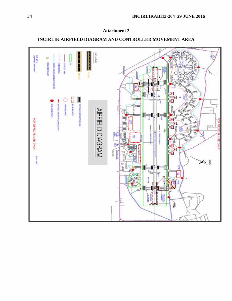
54 INCIRLIKABI13-204 29 JUNE 2016
Attachment 2
INCIRLIK AIRFIELD DIAGRAM AND CONTROLLED MOVEMENT AREA

INCIRLIKABI13-204 29 JUNE 2016 55
Attachment 3
ARM/DE-ARM AREA
Figure A3.1. ARM/DE-Arm Area
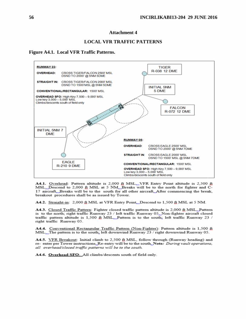
56 INCIRLIKABI13-204 29 JUNE 2016
Attachment 4
LOCAL VFR TRAFFIC PATTERNS
Figure A4.1. Local VFR Traffic Patterns.

INCIRLIKABI13-204 29 JUNE 2016 57
Attachment 5
RADAR TRAFFIC PATTERN
Figure A5.1. Radar Traffic Pattern.

58 INCIRLIKABI13-204 29 JUNE 2016
Attachment 6
ILS CRITICAL AREAS
Figure A6.1. Runway05 Approach End.
Figure A6.2. Runway 23 Approach End.

INCIRLIKABI13-204 29 JUNE 2016 59
Attachment 7
LOCAL AREA CHART
Figure A7.1. Local Area Chart