Embed Size (px)
Citation preview
BY: GASSIE ORRJABARE MITCHELL
Information Systems(Android Application)

Overview of Project
Introduction Purpose of the projectProject PlanUsecase DiagramUsecase SpecificationsBreakdown of individual usecasesDiscuss Sequence DiagramsFunctional TestShow Screen Shots of Application
Overview of Project (Continued)
Discuss ER and Class DiagramData DictionaryDiscuss Dataflow DiagramEvolutionClosing Remarks

Introduction(About us)
Gassie Orr- A fourth year CIS major who graduates in the Spring.
Jabare Mitchell-

Introduction
While in the system class, we the class, came up with a system design that we believe would be beneficial to Florida Agricultural and Mechanical University.
A GPS application for the campus
It will give directions to various buildings, parking lots, and bus routes according to where they are located on the campus.

Introduction
Will also include a variety of special features to go along with this application such as a special events section, which will describe the different types of events going on around the campus.
Another key feature that will be included on our system will be the alerts section. will include our They Towing alert system
application that allows users to be educated about the campus of Florida A&M and also for efficiency when trying to get around on the campus.

Purpose
The purpose of this system is to provide a Navigation system specifically for Florida A&M University.
We also would like for our system to pr0vide a more efficient way of getting around our campus.
….. And of course for an “A” grade!!!

Project Plan
Our project plan consist of 8 steps….1. Start Project2. Project Specifications Finalized3. Android Phone Acquired4. Android App Developer Software Downloaded5. Best GPS and Mapping Systems Chosen6. Application programming Completed7. GPS and Mapping Interface Completed8. Project Completion
Diagram on next slide…
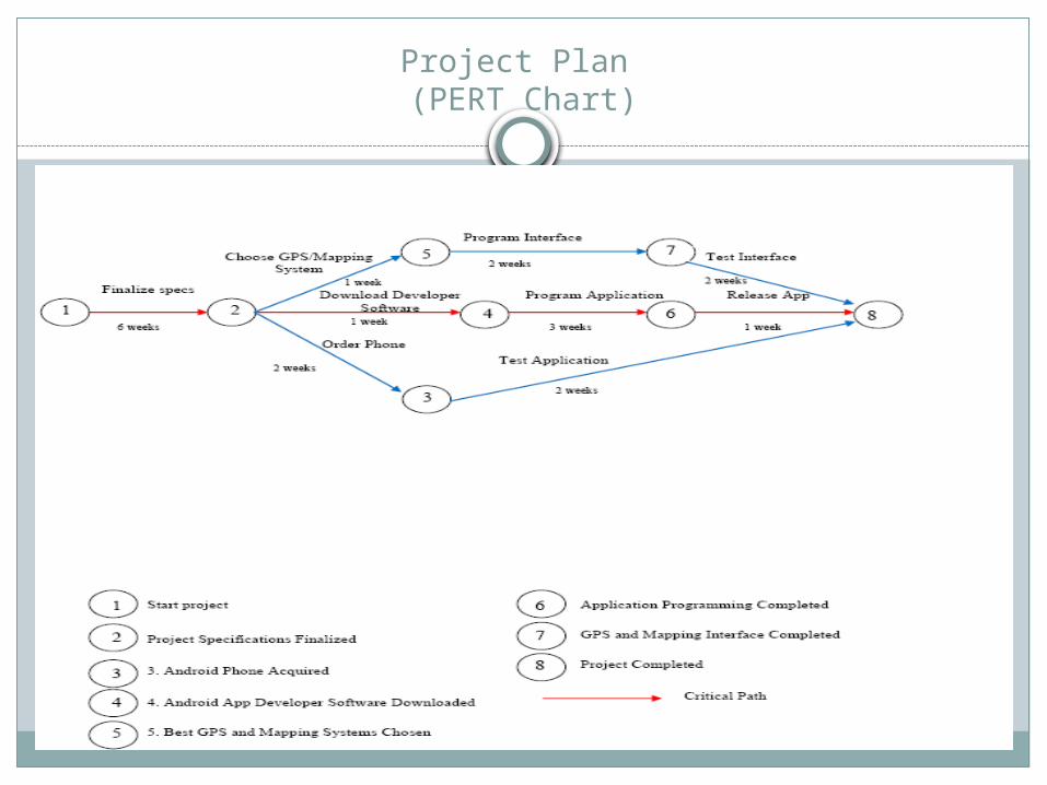
Project Plan (PERT Chart)

Use case Diagram
From a list of stakeholders we narrowed it down to 3 actors.
This diagram shows what the actors are capable of doing, but not limiting them to the things that are around them, because some of the actors can do things other actors can do.
A way of reducing redundancy
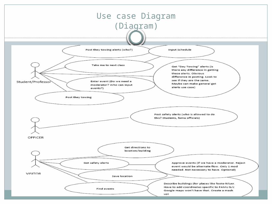
Use case Diagram(Diagram)

Use Case Specifications
Our use case specifications come from the “can do’s” in the Use Case Diagram.
A total of 12 basic features that we believe are vital to our systems success.
Over time new features will be included.For better understanding we will show you the
Use Case Specification each with… Sequence diagram- includes all classes that go along
with the Use case. Function Test Case- an example in words of the use case Screenshots w/ appropriate data.

Use Case Specification(Find a Parking Spot)

Sequence Diagram(Find a Parking Spot)
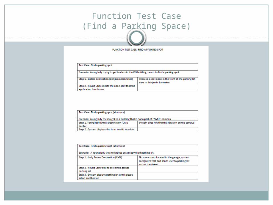
Function Test Case(Find a Parking Space)

Screen Shot (Find A Parking Spot)
Step 1
Step 2

Screen Shot (Find A Parking Spot)
Step 3

Use Case Specification(Take me to next class)

Sequence Diagram(Take Me to Next Class)
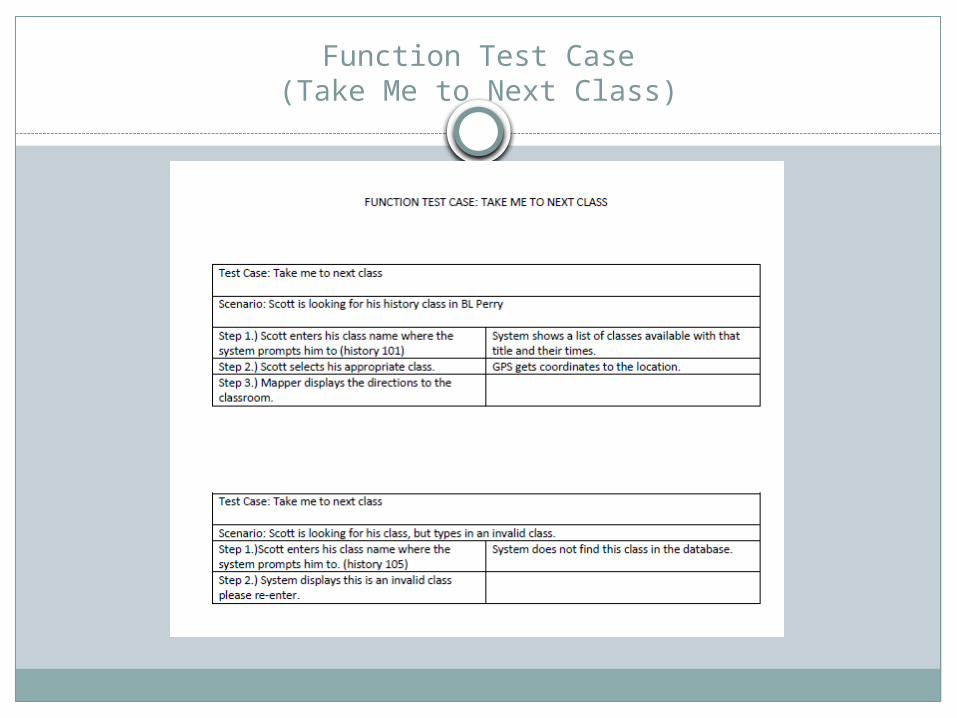
Function Test Case(Take Me to Next Class)

Screen Shot (Take Me to Next Class)
Step 1
Step 2

Screen Shot (Continued)
Step 3
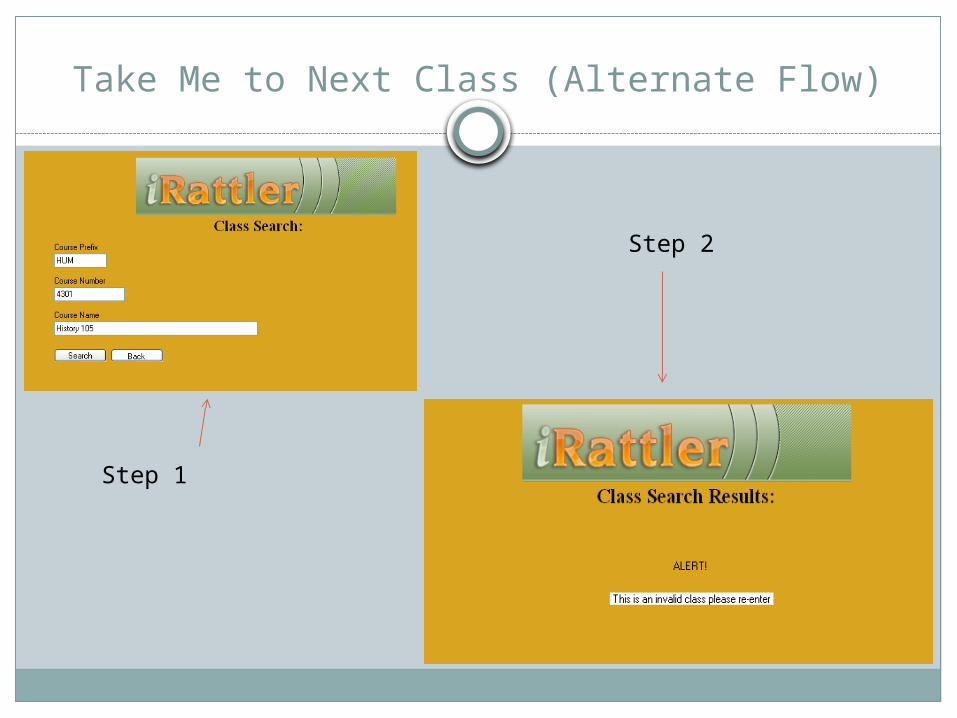
Take Me to Next Class (Alternate Flow)
Step 1
Step 2

Use Case Specification(Get Directions)

Sequence Diagram(Get Directions)

Function Test Case(Get Directions)

Screen Shot (Get Direction to Class)
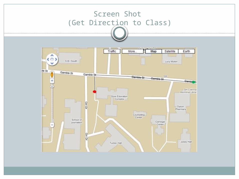
Screen Shot (Get Direction to Class)
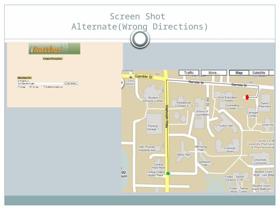
Screen Shot Alternate(Wrong Directions)

Screen Shot Alternate(Wrong Directions)

Use Case Specification(Get Safety Alert)

Sequence Diagram(Get Safety Alert)

Function Test Case(Get Safety Alert)

Screen Shot (Get Safety Alert)

Use Case Specification(Get they Towing Alerts)

Sequence Diagram(Get they Towing Alerts)

Function Test Case(Get they Towing Alerts)
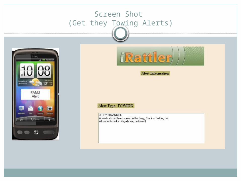
Screen Shot (Get they Towing Alerts)
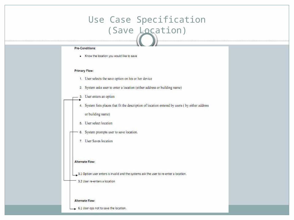
Use Case Specification(Save Location)

Sequence Diagram(Save Location)
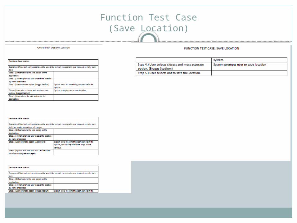
Function Test Case(Save Location)
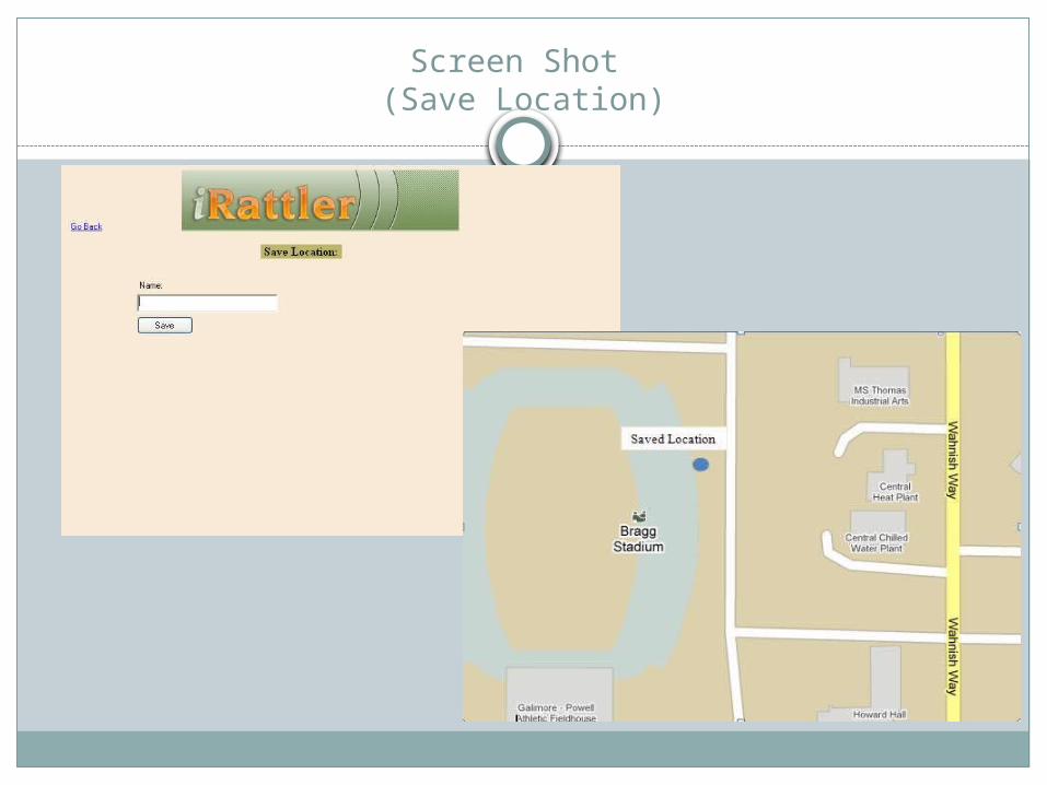
Screen Shot (Save Location)

Use Case Specification(Find Activity/Event)

Sequence Diagram(Find Event)
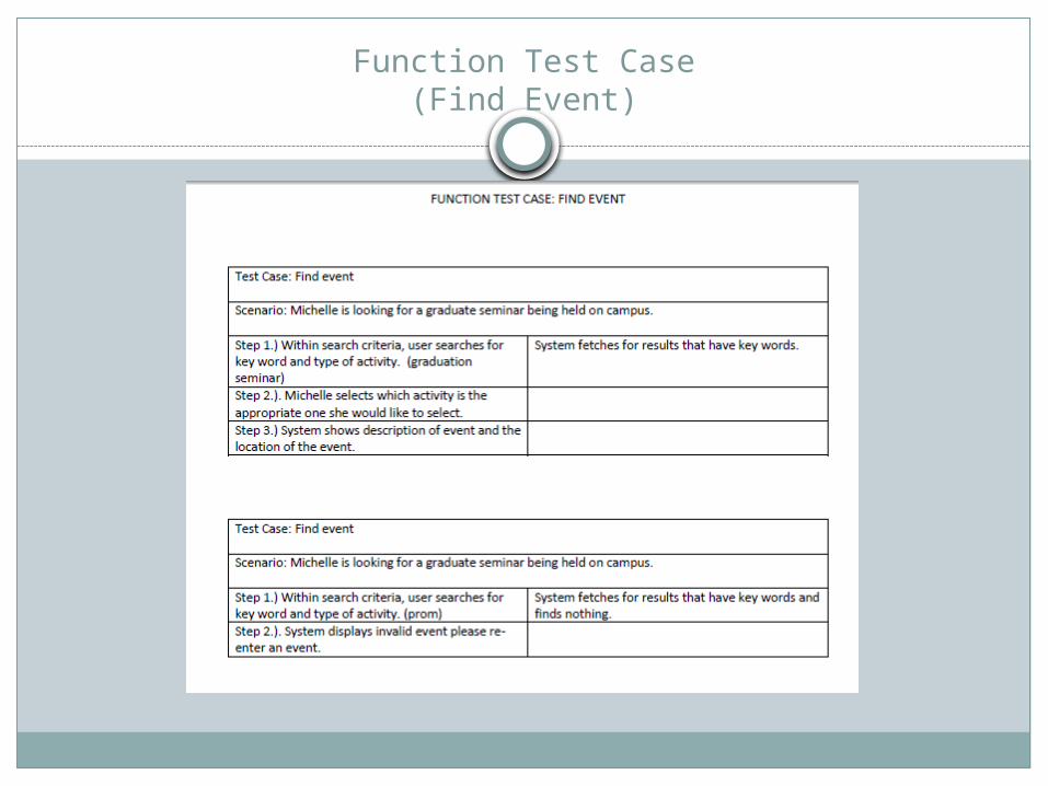
Function Test Case(Find Event)

Screen Shot (Find Event)

Find EventAlternative Screen Shot

Use Case Specification(Enter Activity)
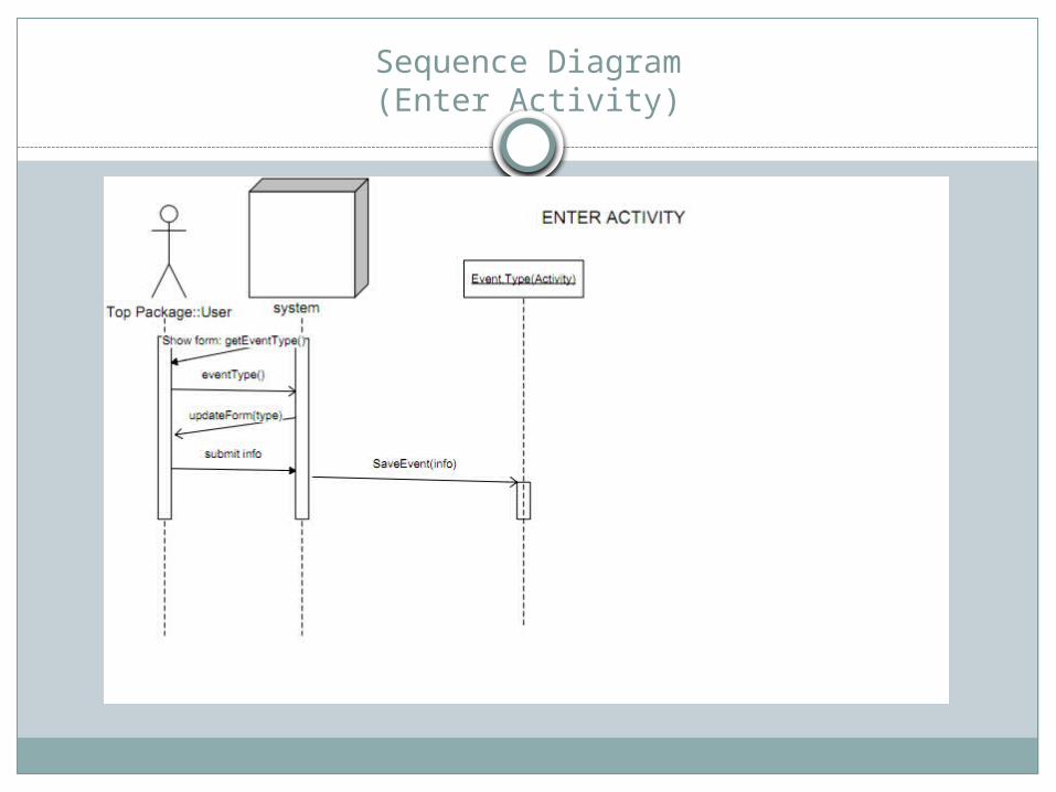
Sequence Diagram(Enter Activity)

Function Test Case(Enter Activity)

Screen Shot (Enter Activity)


Use Case Specification(Post Safety Alerts)

Sequence Diagram(Post Safety Alerts)

Function Test Case(Post Safety Alerts)

Screen Shot (Post Safety Alerts)

Use Case Specification(Post they Towing Alerts)

Sequence Diagram(Post they Towing Alerts)

Function Test Case(Post they Towing Alerts)
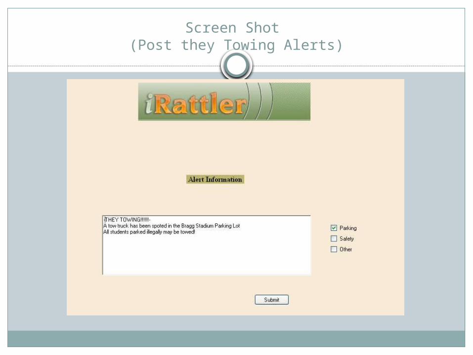
Screen Shot (Post they Towing Alerts)
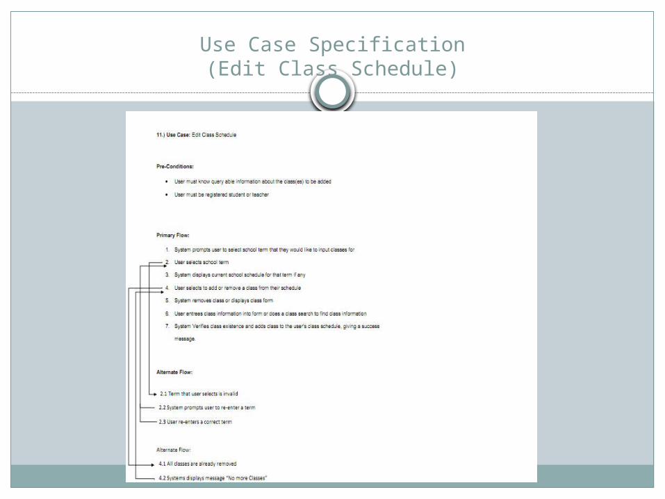
Use Case Specification(Edit Class Schedule)
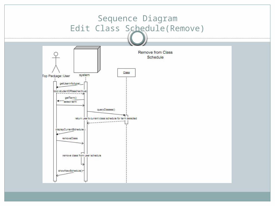
Sequence DiagramEdit Class Schedule(Remove)

Sequence DiagramEdit Class Schedule(Add)
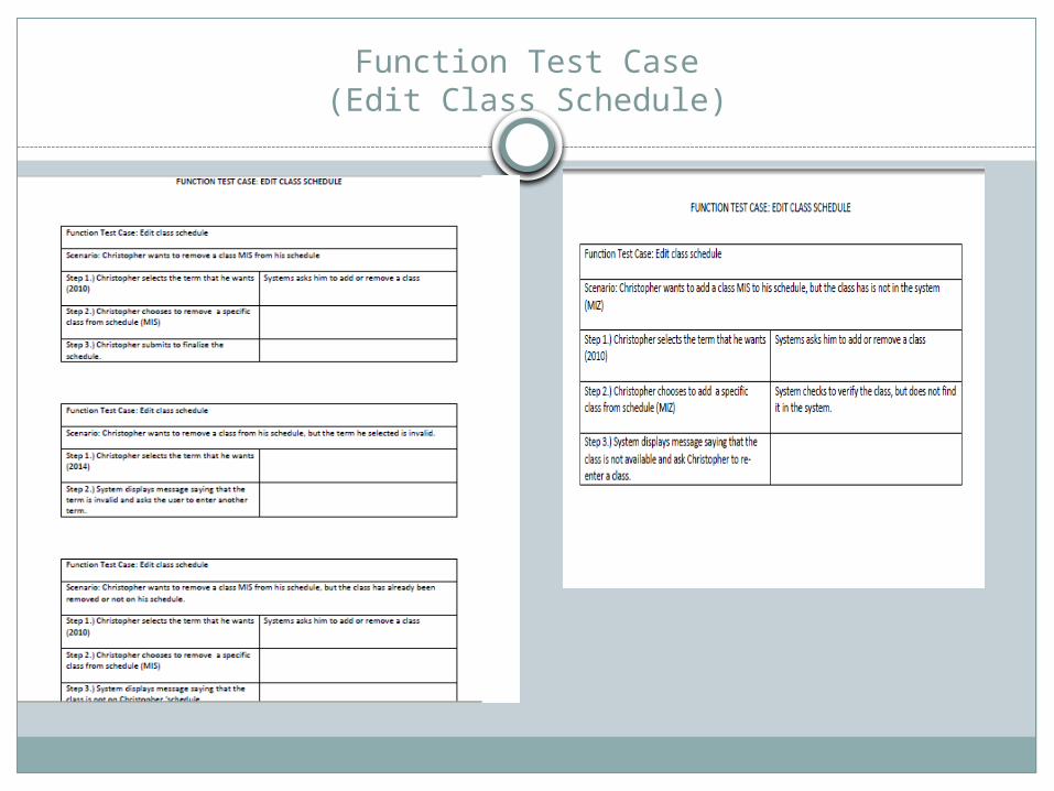
Function Test Case(Edit Class Schedule)

Screen Shot Edit Class Schedule (Add)
Step 1
Step 2

Screen Shot Edit Class Schedule (Add)
Step 3

Screen Shot Edit Class Schedule (Remove)
Step 1
Step 2

Screen Shot Edit Class Schedule (Add)
Step 3
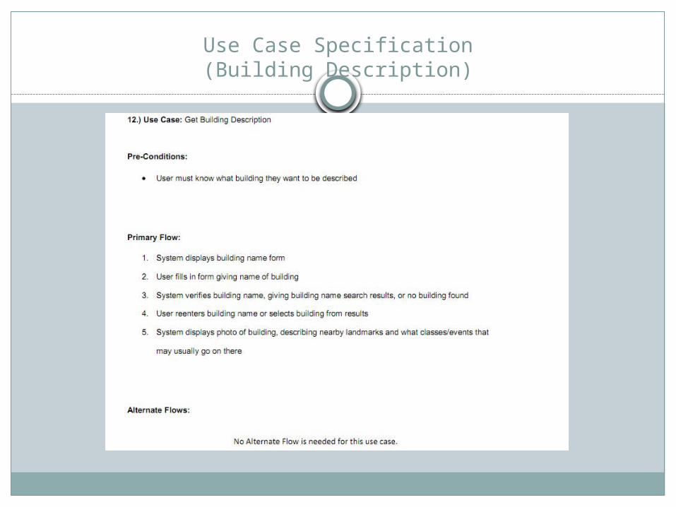
Use Case Specification(Building Description)

Sequence Diagram(Building Description)

Function Test Case(Building Description)

Screen Shot (Building Description)

ER Diagram
The ER Diagram shows the relationship between entities along with the attributes that go along with each of them.

ER Diagram

Data Dictionary
The Data Dictionary is a list of all the Entities we believe that we will need that explain the attributes, the types, the key, and a description.
These are also found on the ER diagram.

Data DictionaryEvents
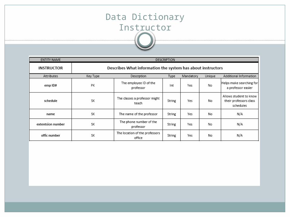
Data DictionaryInstructor
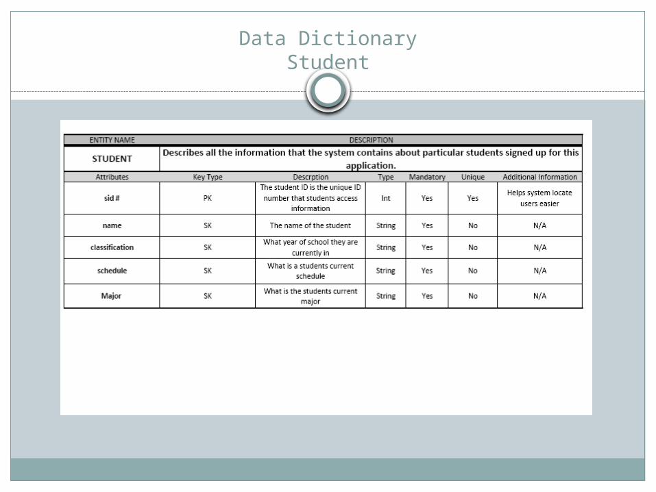
Data DictionaryStudent

Data Dictionary(Room)

Data Dictionary(User)

Data Dictionary(Parking Lot)

Data Dictionary(Officer)

Data Dictionary(location)
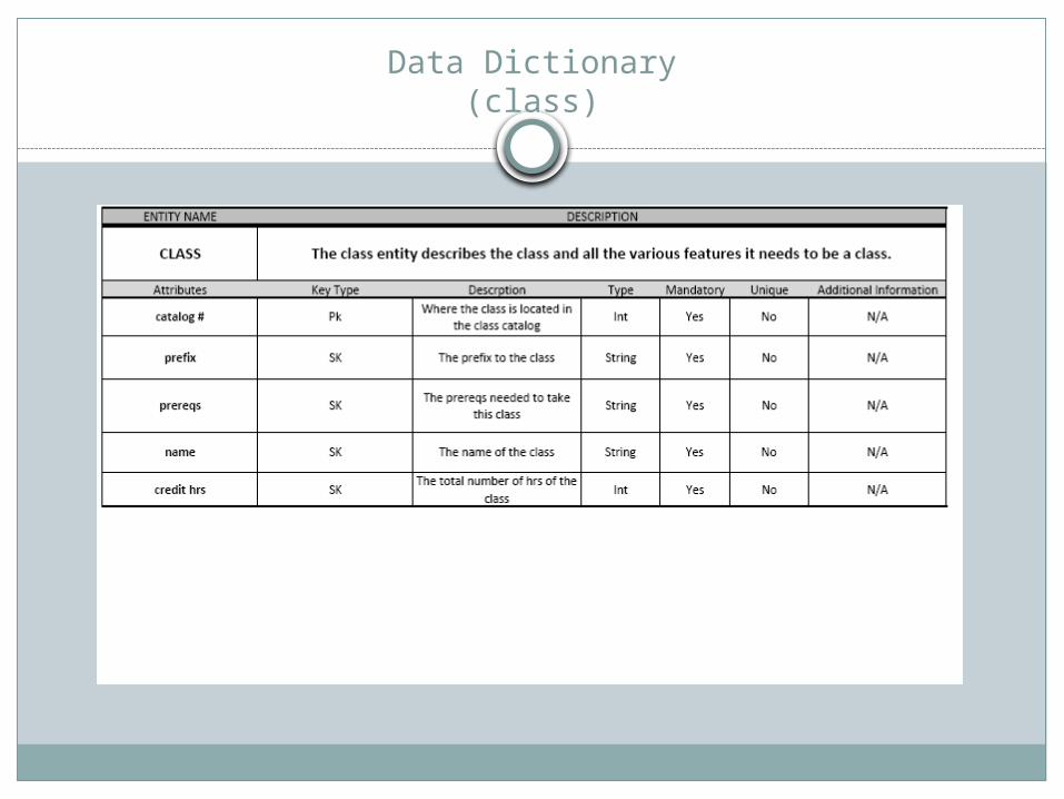
Data Dictionary(class)
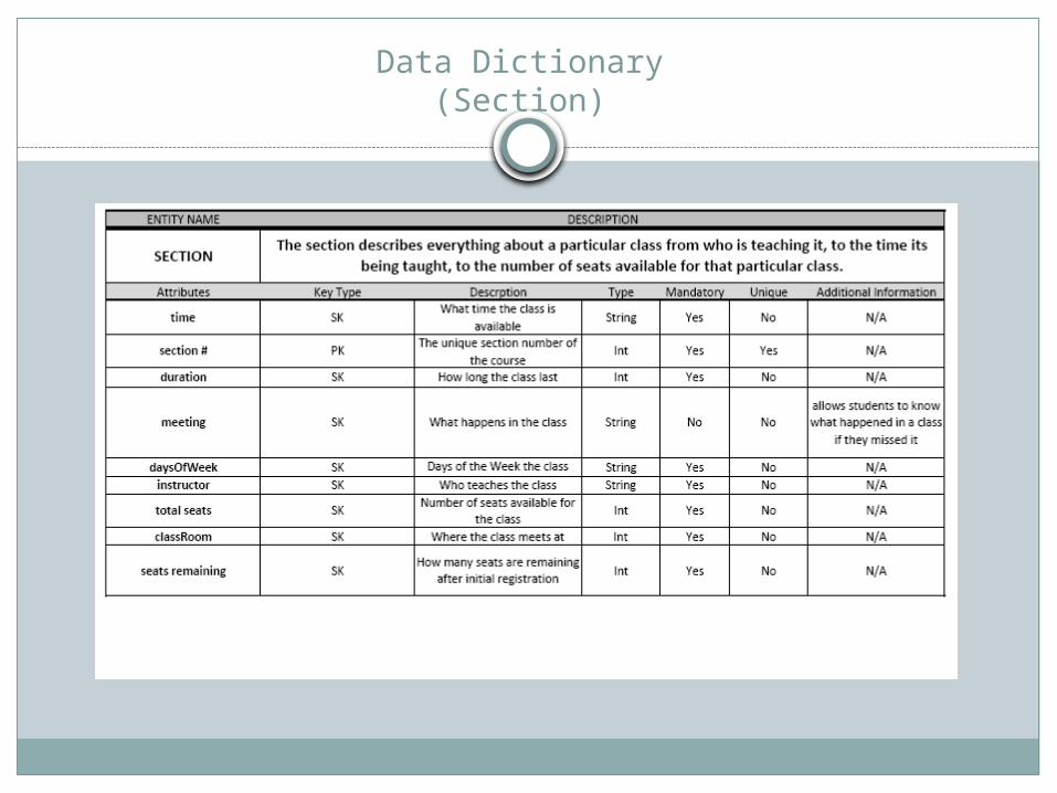
Data Dictionary(Section)

Data Dictionary(building)
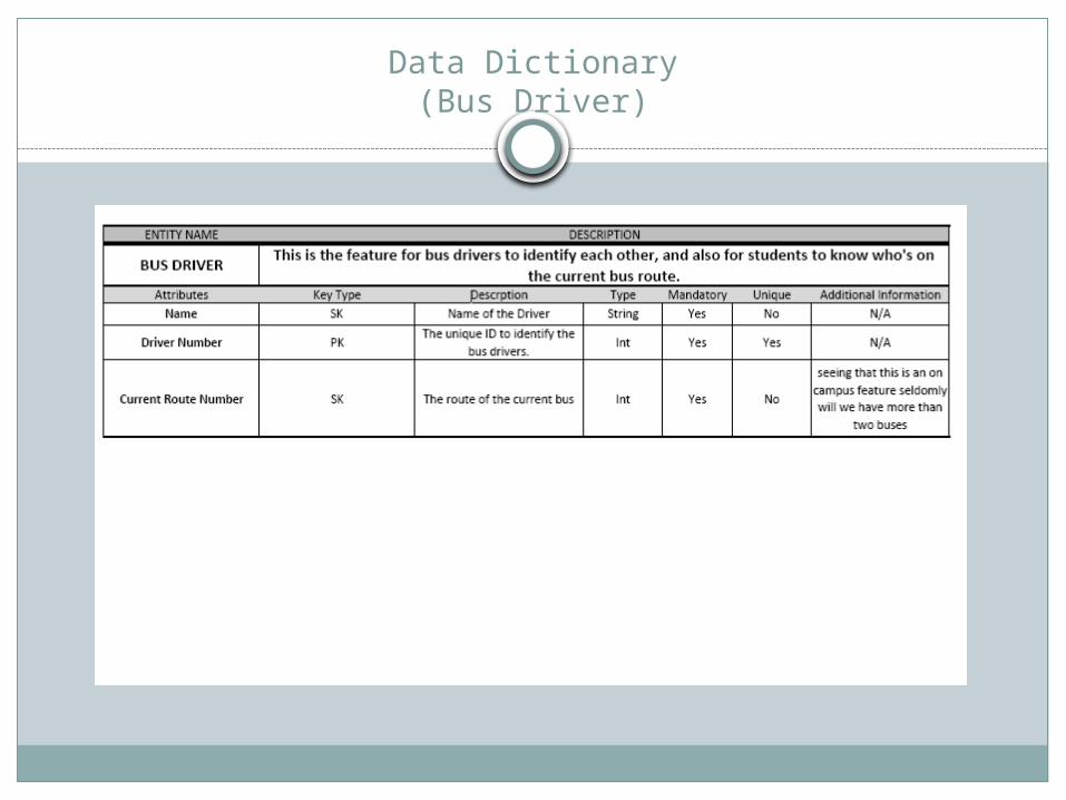
Data Dictionary(Bus Driver)

Dataflow Diagram
The Dataflow Diagram shows the flow of how all the use cases are carried out, it does not show any relationships it just explains the flow of the system.

Dataflow(diagram)

Evolution
Like we stated previously there would be new features that we would like to include on the system.
Here is a list of a couple features we would like to have in design by the time the first system comes out.
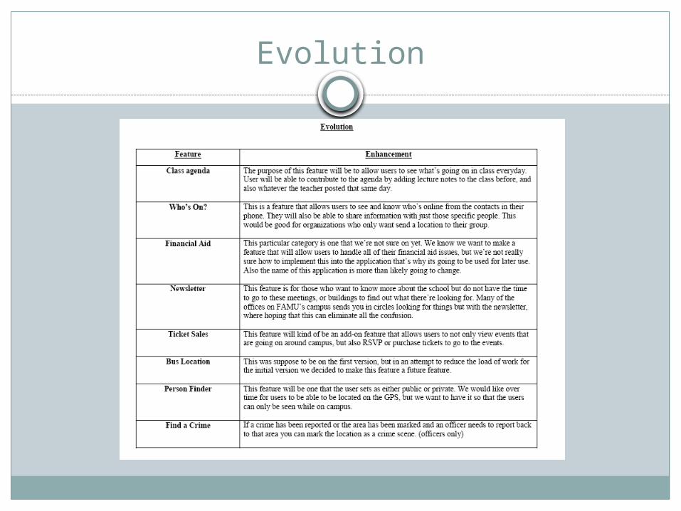
Evolution

Closing Remarks
This completes our system design.Like previously stated the goal is to make
getting around the campus more efficient and effective.
Thank You for viewing…


![ESNARD – BIRD – GASSIE HOME Web viewWhen Gassie [Sr.] acquired the property, ... In 1907, his friends decided to give him a surprise birthday party on his seventy-second birthday](https://img.dokumen.tips/doc/110x75/5a75c9a27f8b9aea3e8cca5a/esnard-bird-gassie-home-doc-file-web-viewwhen-gassie-sr-acquired.jpg)