Embed Size (px)
Citation preview

Rod Tops by
DTS ENTERPRISES INC. 9910 US 31 N. Ellsworth, MI 49729
Factory Five 33 Hot Rod Convertible Top
System Installation and Operation Manual

Contents
• Introduction Section 1
• Component List Section 2
• Pre-installation Checks Section 3
• Installation Procedures Section 4
• Top System Operation Section 5
• Top Maintenance Section 6
• Warrantee Section 7

Introduction Thank you for purchasing a Rod Tops system. Rod Tops offers the
enthusiast a convertible top system that was engineered using experienced
automotive design knowledge. Our engineering approach is to provide a
high quality assembly, drawing on a wide range of proven design
solutions that result in a cost effective solution for low volume body
applications. While it is very important that a top be functional, it must
also be aesthetically pleasing. All of the Rod Tops built by DTS
Enterprises Inc are designed to enhance the look of the vehicle while
providing protection from the elements.
Our goal is to provide you with a top that adds to the usefulness
and enjoyment of your vehicle for many years.
Sincerely,
Dave Draper,
President

Component List 1. Top Stack (left half/right half)
2. 2, 3 & 4 Bow Tubular Center Sections (3)
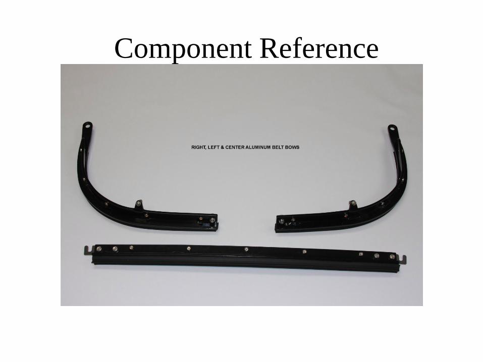
3. 3 Piece Aluminum Belt Line Bows
4. Rear Adjustable Tensioning Links
5. Latch receivers & body mounts
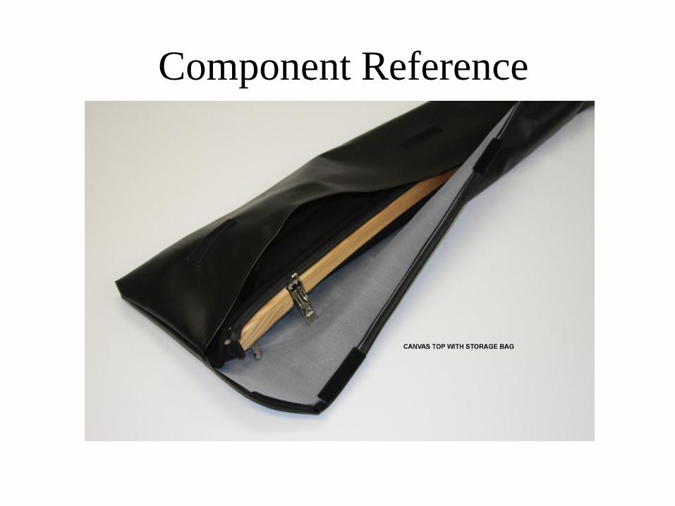
6. Top Canvas With Storage Bag
7. Adjusting and Installation Allen Wrench
9. (Optional) Zip In & Out Side Curtains

Tools Needed
• 1/8” drill bit (pilot hole for body mount)
• ½” drill bit for body mount
• #36 drill bit for 6/32 tap
• 6/32 tap
• Tape measure
• Masking tape

Component Reference

Component Reference
Component Reference

Component Reference

Component Reference
Component Reference

Component Reference
Pre-Installation Checks To insure proper alignment between the top system and the body of the
car, the provided template, or measurements must be used to locate your
windshield. If the windshield is already mounted, these measurements will need to
be established. The distance between the top of the windshield and the “B” pillar or
the lock pillar at the leading edge of the quarter panel (see image on next page). If
the distance from the top edge of the windshield (D) is NOT the same on both sides
of the car, adjustments to the windshield will have to be made, if possible.
The top is designed to allow for minor adjustments at the header clevis.
This adjustment should be used to correct for minor differences in distance that
cannot be completed at the windshield. This adjustment will be covered in the
installation portion of the manual..
It is NOT recommended that the top installation be completed with the
body off of the chassis. The measurements required to locate the top properly may
change greatly with the body off the chassis.
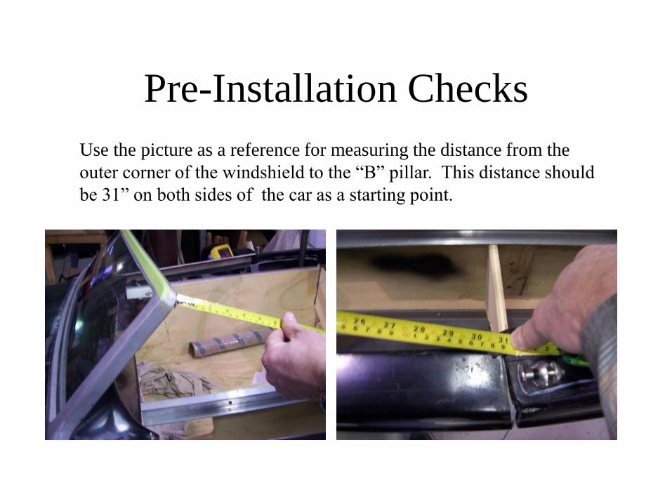
Pre-Installation Checks
Use the picture as a reference for measuring the distance from the
outer corner of the windshield to the “B” pillar. This distance should
be 31” on both sides of the car as a starting point.


Installing the Flush Mounting Kit
For installations on finished vehicles, it is
recommended that the mounting area be
protected with tape.
Cut out and use the supplied templates; one
for the drivers side and one for the
passenger side.
Installation Procedures

Installation Procedures
Align the templates with
the top forward edge of
the door jamb and the
inside curve of the body,
on both sides. Verify the
cross car dimension.
Mark the center of the
hole and drill a ½” hole.
Do not use these they are
not to scale.

Installation Procedures Screw the clevis fully
into the body mount and insert the mount into the hole that was just drilled into the body. Rotate the assembly so the slot in the clevis is pointing forward and place an orientation mark on the clevis and body.
The area surrounding the body grommet may be reinforced on the backside using a bed of plastic filler. The wedges supplied are cut at angles to enable the mount to be square both front to back and also side to side.

Installation Procedure
Using a marker, make two realignment marks at the
intersection of the body mount and the vehicle. Each
clevis is now side specific and should be identified by
the black or white washer at the bottom.
Permanently attach the body mounts using the
mounting wedges and washers. Use lubricant on the
threads to ease installation of the nut. Pay special
attention to the alignment marks. Install the body clevis
checking for proper orientation between the vehicle and
the clevis slot. Adjust as needed.

Installation Procedures Find center of the windshield and make a small mark. Next find
center of the wooden header and make a mark. Place header on
windshield, this will be used to place latch receivers.
Section 4.8
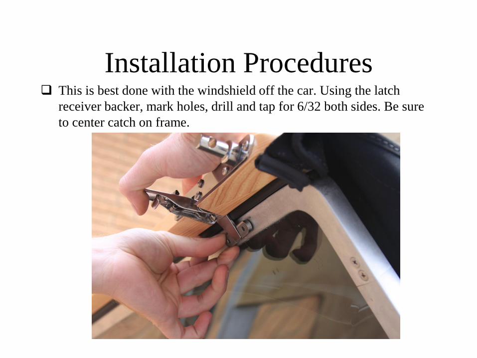
Installation Procedures This is best done with the windshield off the car. Using the latch
receiver backer, mark holes, drill and tap for 6/32 both sides. Be sure
to center catch on frame.

Installation Procedures

Installation Procedures Place the wooden header on the windshield and adjust latches to
crush seal about ¼”.

Installation Procedures Take the outer belt bows and attach them to the mounts.

Installation Procedures Install the center belt bow to the outers.
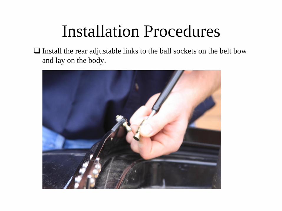
Installation Procedures Install the rear adjustable links to the ball sockets on the belt bow
and lay on the body.
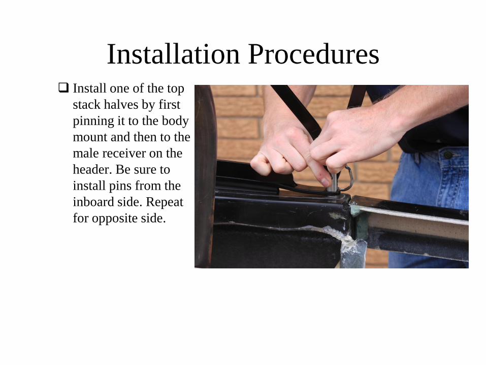
Installation Procedures Install one of the top
stack halves by first
pinning it to the body
mount and then to the
male receiver on the
header. Be sure to
install pins from the
inboard side. Repeat
for opposite side.

Installation Procedures

Installation Procedures

Installation Procedures There are two quarter
turn spring plungers
that lock the side rails
on the top stack
halves.
These need to be
locked. By a turn and
pull motion they are
allowed into the
mating holes on the
rails. Leaving them
loose while erecting
the top helps mate the
rails to the header.
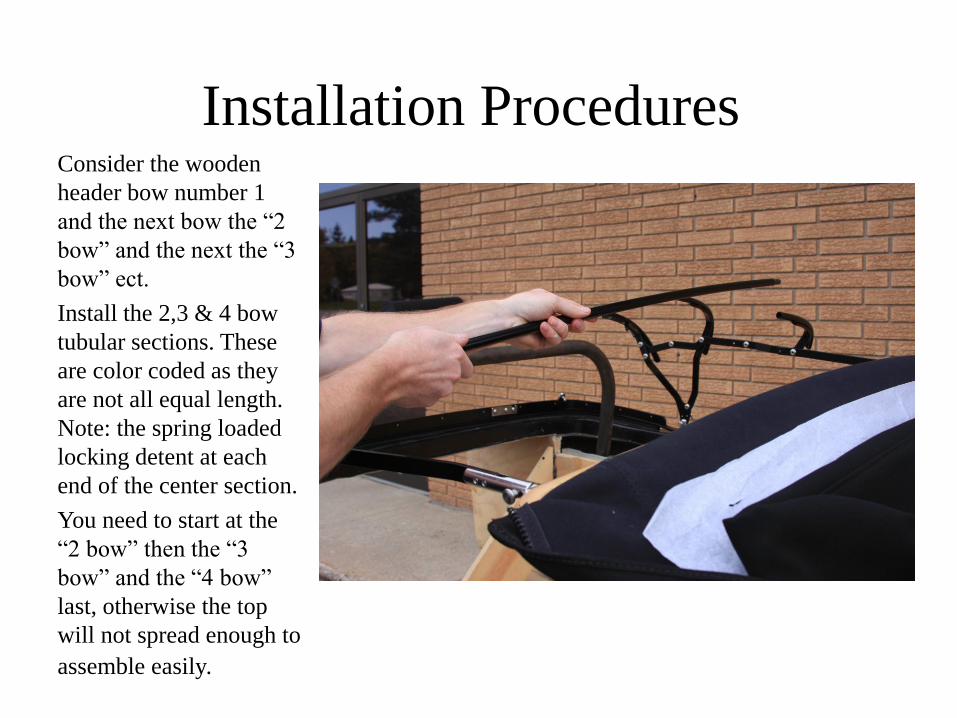
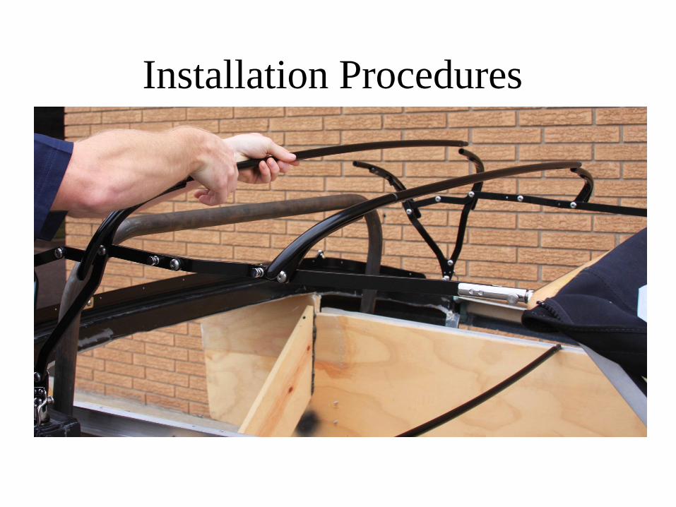
Installation Procedures Consider the wooden
header bow number 1
and the next bow the “2
bow” and the next the “3
bow” ect.
Install the 2,3 & 4 bow
tubular sections. These
are color coded as they
are not all equal length.
Note: the spring loaded
locking detent at each
end of the center section.
You need to start at the
“2 bow” then the “3
bow” and the “4 bow”
last, otherwise the top
will not spread enough to
assemble easily.
Installation Procedures

Installation Procedures Now install the
adjustable links into
the pocket on the back
side of the 4 bows and
lightly tighten.

Installation Procedures Next pull the canvas over the top.

Installation Procedures Hook the canvas over
the wire loop on both
sides located by the
body mount.

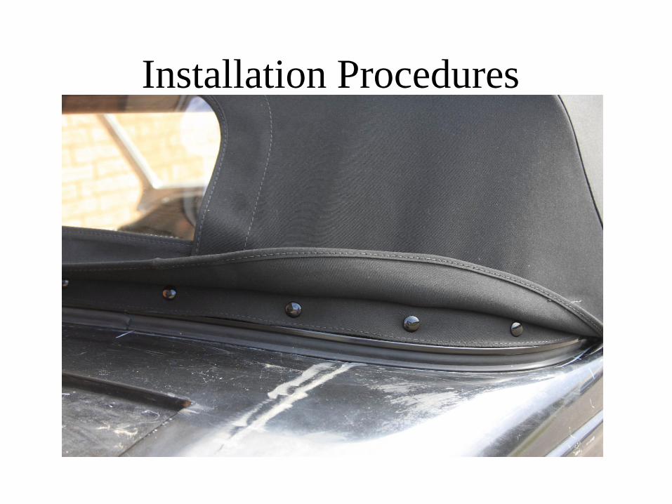
Installation Procedures Start with the center
snaps and work
outward snapping the
canvas to the belt bow.
Installation Procedures

Installation Procedures On the inside of the
top there are two
listings with velcro
these need to be
wrapped around the 2
and 3 bows.
There is also a flap
with a zipper, this
must go around the “4
bow” and back to the
zipper. This keeps
tension on the canvas
when the rear window
is zipped down.

Installation Procedures Adjusting and sealing the
top is quite simple. Turn
the rear adjustable links
until the rear belt bow
seats snuggly against the
body. If you find it needs
more length the clevis
that is attached to the
header is able to extend
rearward. Although it is
optimal to leave it in a
neutral position. This
adjustment is better
suited to make up for
windshield
misalignment. Loosen
both allen screws and
adjust forward or back as
needed.
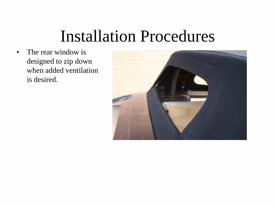
Installation Procedures • The rear window is
designed to zip down
when added ventilation
is desired.

Top System Operation The installation of the top is now complete.
The top can be removed by reversing the installation process and
storing the top in the trunk.
Enjoy and remember “Rod Tops Has You Covered”
Section 5.4

Side Curtains • There is a snap template for
adding the snaps to the windshield on both sides. It requires drilling and tapping 10/32 threads. Using a # 21 drill.

Side Curtains
• One more snap is required
on the outboard portion of
the dash, install using the
supplied template. This is
a directional snap, it can
only be taken of in one
direction. Pick up in front
and pull backwards.

Side Curtains • Zip the side curtain in and
attach all snaps. The rear Velcro
strap goes around the body
mount and back to itself.

Side Curtains • The finished product is a nice
tight fitting and functional
window. Enjoy and remember
“Rod Tops Has You Covered”

Top Maintenance The Rod Top system is designed to require little maintenance. All
pivots used in the assemble of the top are stainless steel with self lubricating nylon bushings and should only need maintenance if damaged.
If for any reason, parts should ever need to be replaced or repaired, contact DTS Enterprises Inc at 1-(888)-Rod-Tops for replacement parts.
The canvas on the top should be washed periodically to maintain its appearance. Do not use harsh cleaning agents or stiff bristle brushes. Use a mild detergent and water when cleaning the top, Ragg Top Cleaner is a good brand. The top may be blown dry with a air nozzle or use a wet dry vacuum. Allow top to fully dry prior to storing in supplied storage bag.
Special attention should be paid to the welting sewn to the top in the area of the beltline bow. This is the portion of the top that contacts the body and should be kept free of dirt and abrasive contamination.
Section 7

Warranty
Your Rod Top system is guaranteed to be free of manufacturers
defects. Any failures related to the manufacturing of the top up to
one year from the date of sale will be repaired. To complete a
warranty claim contact DTS Enterprises Inc. at 1-(888)-Rod-Tops
and they will repair or replace any of the defective parts.
If any portion of the top system must be sent in for repair, the costs
related to shipping are not covered under warranty. This is a parts
and labor only warranty.
Section 8