Embed Size (px)
Citation preview

INS
TALL
AT
ION
GU
IDE
Introduction >
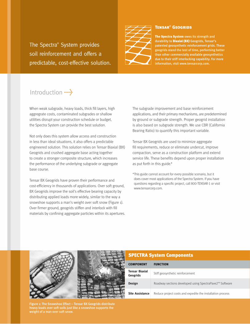
Figure 1: The Snowshoe Effect – Tensar BX Geogrids distributeheavy loads over soft soils just like a snowshoe supports theweight of a man over soft snow.
When weak subgrade, heavy loads, thick fill layers, high
aggregrate costs, contaminated subgrades or shallow
utilities disrupt your construction schedule or budget,
the Spectra System can provide the best solution.
Not only does this system allow access and construction
in less than ideal situations, it also offers a predictable
engineered solution. This solution relies on Tensar Biaxial (BX)
Geogrids and crushed aggregate base acting together
to create a stronger composite structure, which increases
the performance of the underlying subgrade or aggregate
base course.
Tensar BX Geogrids have proven their performance and
cost-efficiency in thousands of applications. Over soft ground,
BX Geogrids improve the soil’s effective bearing capacity by
distributing applied loads more widely, similar to the way a
snowshoe supports a man’s weight over soft snow (Figure 1).
Over firmer ground, geogrids stiffen and interlock with fill
materials by confining aggregate particles within its apertures.
The subgrade improvement and base reinforcement
applications, and their primary mechanisms, are predetermined
by ground or subgrade strength. Proper geogrid installation
is also based on subgrade strength. We use CBR (California
Bearing Ratio) to quantify this important variable.
Tensar BX Geogrids are used to minimize aggregate
fill requirements, reduce or eliminate undercut, improve
compaction, serve as a construction platform and extend
service life. These benefits depend upon proper installation
as put forth in this guide.*
*This guide cannot account for every possible scenario, but itdoes cover most applications of the Spectra System. If you havequestions regarding a specific project, call 800-TENSAR-1 or visitwww.tensarcorp.com.
The Spectra® System provides
soil reinforcement and offers a
predictable, cost-effective solution.
Tensar®
Geogrids
The Spectra System owes its strength anddurability to Biaxial (BX) Geogrids, Tensar’spatented geosynthetic reinforcement grids. Thesegeogrids stand the test of time, performing betterthan other commercially available geosyntheticsdue to their stiff interlocking capability. For moreinformation, visit www.tensarcorp.com.
SPECTRA System Components
COMPONENT FUNCTION
Tensar BiaxialGeogrids
Stiff geosynthetic reinforcement
Design Roadway sections developed using SpectraPave2™ Software
Site Assistance Reduce project costs and expedite the installation process

• When placing an order, communicate all pertinent
project and/or application criteria, including certification
requirements, if any, with your Tensar Earth Technologies
(TET) representative. It is normally advisable to schedule
a pre-construction conference with this representative
and any other appropriate parties at this time.
• Upon delivery, check the BX Geogrid roll labels to
verify that the intended product has been received.
For instance, BX1100 and BX1200 Geogrids have a
similar appearance, but different structural characteristics
so their distinction is important. Inspect the geogrid
to ensure it is free of any flaws or damage that may
have occurred during shipping or handling.
1. Getting Started >
• Store Tensar BX Geogrids in a manner that prevents
excessive mud, wet concrete, epoxy or other deleterious
materials from coming in contact with and affixing to the
geogrid. Store geogrids above -20˚F (-29˚C) and avoid
handling below 14˚F (-10˚C) – the glass-transition
temperature for polypropylene used in BX Geogrids.
Tensar BX Geogrids may be stored uncovered for up to
six months in direct exposure to sunlight without any loss
in certifiable structural properties (contact TET if longer
exposure is anticipated). BX Geogrids may be stored
vertically (rolls stood on end) or, typically, horizontally in
stacks up to five rolls high (Figure 2).
• Anticipate potential issues and resolve them with
TET prior to construction. To contact the local TET
representative for your area, call 800-TENSAR-1.
2
Figure 2: Storing the BX Geogrid rolls (horizontally).

2. Site Preparation >
• Clear, grub and excavate (if necessary) to the design
grade, stripping topsoil, deleterious debris and
unsuitable material from the site. For very soft soils
(CBR < 0.5), it may be beneficial to minimize subgrade
disturbance and leave root mats in place, cutting stumps
and other projecting vegetation as close and even to the
ground surface as practical (Table 1). For moderately
competent soils (CBR > 2), it may be prudent to lightly
proof roll the subgrade to locate unsuitable materials.
When possible, backdrag to smooth out any ruts.
• Smooth grade and compact the soils using appropriate
compaction equipment. Swampland, peat, muskeg or
marshes may be difficult to smooth grade and/or compact.
In these situations, create a surface that is as uniformly
smooth as possible. Grade or crown the surface for
positive drainage away from the construction zone.
Note: Routine construction procedures are normallyrecommended for site preparation. Special measuresare rarely required to accommodate Tensar BX Geogrids.
Figure 3: Rolling outthe BX Geogrid.
Table 1: Summary of BX Geogrid Installation Parameters
SubgradeStrength
Clear All Vegetation? BX Orientation3 BX Overlap4 Ties?1,2 Direct Traffic?5 Geotextile?6
CBR ≤ 0.5 N T or L 3 ft. Y N Analysis Req’d
0.5 ≤ CBR ≤ 2 Usually L 2 – 3 ft. N N Analysis Req’d
2 ≤ CBR ≤ 4 Y L 1 – 2 ft. N Limited Analysis Req’d
4 ≤ CBR Y L 1 ft. N Y N
Notes:1. Summary is a generalized presentation; see text for specifics.2. Y = Yes, normally required; N = No, normally not required.3. Geogrid Orientation (roll axis in relation to traffic): T = Transverse, L = Longitudinal.4. General Geogrid Overlap Rule: Overlap = 3 ft. for CBR ≤1; Overlap = 1 ft. for CBR ≥ 3; interpolate between.5. Direct Traffic pertains only to conventional rubber-tired equipment.6. Analysis Req’d = Geotextile required only if filtration criteria not met by aggregate fill.
• Place the rolls of BX Geogrid* in position, cut the
roll bands and manually unroll the material over the
prepared surface (Figure 3). In subgrade improvement
applications, this surface will always be the subgrade.
In base reinforcement applications, it may be the
subgrade, the subbase or at an elevation (say,
mid-depth) within the base course.
*Tensar Earth Technologies manufactures several differenttypes of BX Geogrids. Selection and optimization dependson structural performance requirements, subgrade and fillparameters, economic considerations and local availability.

• On roads, unroll the geogrid in the direction of travel so
that the long axis of the roll is parallel with channelized
traffic patterns. For very soft subgrades (CBR < 0.5),
unrolling geogrid transversely or perpendicular to the
roadway embankment alignment, may be preferred,
particularly if lateral spreading and separation of
overlaps is a concern (Table 1).
• Overlap adjacent rolls along their sides and ends in
accordance with Table 1.
• Overlap (“shingle”) geogrids in the direction the fill will
be spread (Figure 4) to avoid “peeling” of geogrid
at overlaps by the advancing fill. To expedite “shingling”,
consider placing rolls at the far end of the coverage area
first, and work toward the near end from where the fill
will be advanced.
3. Placing Overlapping Geogrid >
• Adjacent geogrid rolls are normally not connected to
one another, particularly if fill is placed and spread as
described herein (Table 1). A notable exception is over
very soft subgrades (CBR < 0.5) where nylon cable ties
can be effective in helping maintain overlap dimensions.
These ties are not considered structural connections,
but rather construction aids.
• Cut and overlap the geogrid to accommodate curves
(Figure 5). Cutting may be done with sharp shears, a
knife-like implement or handheld power (i.e., “cutoff ”)
saws (Figure 6). (Wear appropriate safety equipment.)
Cut grid to conform to manhole covers and other
immovable protrusions.
• Place geogrids in daily work sections so that proper
alignment is maintained.
Figure 5: Placing BX Geogrid to accommodate curves.
Figure 6: Using a handheld power saw to cut geogrid.
Figure 4: Geogrid should overlapin the direction of advancing fill.
4
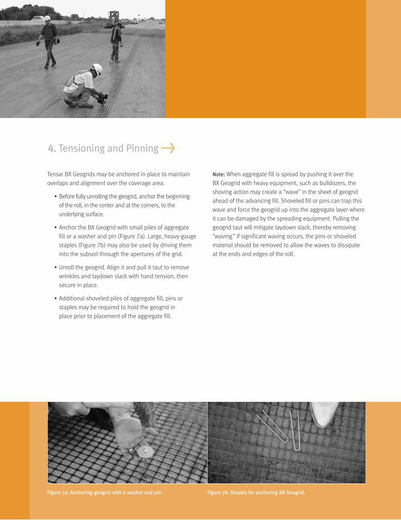
Tensar BX Geogrids may be anchored in place to maintain
overlaps and alignment over the coverage area.
• Before fully unrolling the geogrid, anchor the beginning
of the roll, in the center and at the corners, to the
underlying surface.
• Anchor the BX Geogrid with small piles of aggregate
fill or a washer and pin (Figure 7a). Large, heavy-gauge
staples (Figure 7b) may also be used by driving them
into the subsoil through the apertures of the grid.
• Unroll the geogrid. Align it and pull it taut to remove
wrinkles and laydown slack with hand tension, then
secure in place.
• Additional shoveled piles of aggregate fill, pins or
staples may be required to hold the geogrid in
place prior to placement of the aggregate fill.
4. Tensioning and Pinning >
Note: When aggregate fill is spread by pushing it over the
BX Geogrid with heavy equipment, such as bulldozers, the
shoving action may create a “wave” in the sheet of geogrid
ahead of the advancing fill. Shoveled fill or pins can trap this
wave and force the geogrid up into the aggregate layer where
it can be damaged by the spreading equipment. Pulling the
geogrid taut will mitigate laydown slack, thereby removing
“waving.” If significant waving occurs, the pins or shoveled
material should be removed to allow the waves to dissipate
at the ends and edges of the roll.
Figure 7a: Anchoring geogrid with a washer and pin. Figure 7b: Staples for anchoring BX Geogrid.

Figure 8: Dumping aggregatefill on top of BX Geogrid overcompetent subgrade.
5. Dumping and Spreading Aggregate Fill >
• Generally, at least 6 inches is required for the initial lift
thickness of aggregate fill over BX Geogrids. However,
for very soft conditions, a significantly thicker fill layer
may be required to prevent excessive rutting and/or
bearing capacity failure.
• Over relatively competent subgrades (CBR > 4, see
Table 1), aggregate fill may be dumped directly onto
the geogrid (Figure 8). Standard, highway-legal rubber-
tired trucks (end dumps and belly dumps) may drive
over the geogrid at very slow speeds (less than 5 mph)
and dump aggregate fill as they advance, provided this
construction traffic will not cause significant rutting
upon bare subgrade. Turns and sudden starts and
stops are not advised.
• Over softer subgrades (CBR < 2), back trucks up and
dump fill upon previously placed fill (Figure 9a). For very
soft subgrades (CBR < 0.5), limit the fill pile height to
avoid overstressing caused by excessive dead loads.
• Do not drive tracked equipment directly on the
BX Geogrid. Ensure at least 6 inches of aggregate fill
is spread between the geogrid and tracked equipment
(Figure 9b).
• Also, only operate rubber-tired equipment directly on the
geogrid if the underlying subsoil is not prone to rutting
under limited construction traffic.
• Over softer subgrades (CBR < 2), a light-weight, low
ground pressure (LGP) dozer is recommended to evenly
push out the fill over the exposed geogrid.
• Care should be taken not to catch the dozer blade or
other equipment on the BX Geogrid. The dozer blade
should be raised gradually as each lift is pushed
out over the BX Geogrid. The desired effect is fill
that cascades onto the geogrid, rather than being
pushed into it.
• When building over a soft subgrade, it is desirable
to work from stronger to weaker areas.
• Be aware of BX Geogrid overlaps and advance the
aggregate fill with the shingle pattern.
Figure 9b: Spreading aggregate fill over BX Geogrid.Figure 9a: Dumping aggregate fill on top of BX Geogrid oversoft subgrade. 6

6. Compacting >
• Standard compaction methods may be used unless
the soils are very soft. In these cases, static instead of
vibratory compaction is prudent, particularly over silty
subgrades. Compaction is then achieved using a light
roller. Keeping fill moisture content near optimum will
make compaction more efficient. Water spray is most
effective with sand fill (see Figure 10). For construction
over very soft soils, compaction requirements are
normally reduced for the initial lift.
• If rutting or severe pumping occurs under truck or dozer
traffic, fill should be added immediately to strengthen
the section. Silty subgrades are particularly prone to
pumping. In some cases, it may be prudent to cease
operations for a period of time, allowing pore pressures
to dissipate and the subgrade to stabilize.
Note: If the aggregate fill thickness is insufficient to supportimposed load(s), deep rutting will result.
Figure 10: Moistening the fill before compaction. Figure 11: Compacting the aggregate fill.
• Compact aggregate fill to project specifications, after
it has been graded smooth and before it is subject to
accumulated traffic (Figure 11). Inadequate compaction
will result in surface rutting under wheel loads. This
rutting reduces the total effective thickness of the fill
and increases stress on the subgrade.
Note: Compaction equipment and methods should beappropriate for the type of fill being used, its thicknessand the underlying subgrade conditions.

Make Repairs
• If Tensar BX Geogrids become damaged during or after
installation, repair them by patching the area.
• Remove fill from the surface of the damaged geogrid
and clear a 3 foot area around the damage.
• The geogrid patch should cover the damaged area
and extend 3 feet beyond it in all directions.
Don’t Grade Out Ruts
• If deep rutting occurs beneath truck wheels, do not
grade out the ruts. Rutting is normally indicative of fill
that is too thin, too wet or inadequately compacted.
Grading out the rut will reduce aggregate fill thickness
between the wheel paths and may lead to geogrid
exposure.
• Fill in the ruts with additional specified aggregate fill
and compact. This places extra fill where it’s needed
and may prevent further rutting under channelized traffic.
• Crown the fill during the grading process to ensure
rainfall runoff and to prevent fill saturation.
7. Special Considerations >
Cold Weather
• Cold temperatures increase BX Geogrid stiffness; warm
temperatures decrease it. From a handling perspective,
rolls will have “memory” on cool mornings that relaxes with
the warmth of solar radiation. Securing roll ends before
kick out will prevent the geogrid from rolling back up.
• At sub-freezing temperatures, BX Geogrid is less
impact resistant and can be fractured with dynamic
force (i.e., striking with a hammer). Other aspects of
dynamic loading associated with very cold temperatures
should be avoided. For example, direct trafficking by
rubber-tired equipment atop geogrid is permissible
when the subgrade is competent. However, it’s not
advisable at very cold temperatures.
Aggregate Fill Considerations
• The preferred gradation for base reinforcement
applications is well-graded crushed aggregate fill with
a maximum particle size of 1- inches and less than
10% fines (passing #200 sieve). The gradations listed
in Table 2 (below) provide good stability and low
moisture susceptibility. For subgrade improvement
applications, any clean granular fill may be acceptable.
8
Tensar BX Geogrid Roll Characteristics
ProductRoll Width Roll Length Roll Weight Roll Area
(m) (ft) (m) (ft) (kg) (lbs) (m2) (sy)
BX110047 3 9.8 75 246 45.6 100.5 225 268
BX110075 4 13.1 75 246 61.2 135 300 358.6
BX120040 3 9.8 50 164 46.3 102 150 179.3
BX120060 4 13.1 50 164 62.6 138 200 239.1
BX130060 4 13.1 50 164 50.5 111.5 200 239.1
Table 2: Preferred Fill Gradation
Size % Fines
1- in. 100
: in. 50 – 100
#4 25 – 50
#40 10 – 20
#100 5 – 15
#200 less than 10

• Over relatively competent subgrades (CBR > 2), gradation
and moisture content of aggregate fills are key elements
for stability. (Recycled Portland Cement Concrete meeting
this gradation is often ideal.) Soft subgrades (CBR < 2)
are normally characterized by elevated moisture
contents. Care must be taken to ensure that the moisture
in them is not trapped, which induces porewater
pressure and could result in pumping. For this reason,
it is important that aggregate fill be non-plastic and the
fines limited to less than 10%.
• BX Geogrids will structurally enhance coarser or finer
fill gradations, as long as the aggregate fill is compacted
and placed at or just below optimum moisture content.
For coarser fill, a graded filter analysis is recommended
to guard against potential contamination from the
underlying subgrade (see Table 1). If the aggregate fill
does not meet the requirement(s) of a graded filter
over soft and saturated clays and silts, a non-woven
geotextile should be placed beneath the geogrid.
• Do not use uniformly sized coarse fill as it does not
compact well and will rut under wheel loading, despite
the improved stability brought about by BX Geogrids.
• The moisture content of the fill should not exceed
optimum. Wet fill is not easy to compact and will rut
under wheel loading.
Preferred Equipment
• Soft Ground – the preferred equipment imposes low
contact pressure on the ground surface. This may be
done with smaller machinery, wide tires and/or LGP
tracks. Equipment that concentrates heavy loads over
relatively small contacts, such as front-end loaders,
are not recommended. In all soft ground cases, fill must
be sufficiently thick to avoid overstressing the underlying
soils and BX Geogrid.
• Competent Ground – the preferred equipment
maximizes productivity for specific construction
requirements. Over competent ground, geogrids
can be trafficked directly by rubber-tired equipment,
making hauling equipment (i.e., dump trucks) and
spreading equipment (i.e., motor graders) ideal (Figure 12).
Spreader boxes are not recommended – wrinkling in the
geogrid between the screed and wheels of the box and
dump trucks can cause slack to become trapped, raising
the geogrid up into the aggregate layer.
Excavating through BX Geogrid
• When confined beneath and within compacted fill,
the geogrid should pose no significant threat to
post-construction activities like utility trenching or
driving/auguring supports for rails, signs or standards
(Figure 13).
Figure 13: A backhoe excavation through BX Geogrid.Figure 12: Geogrid can be trafficked directly by rubber-tired equipment.

8. SpectraPave2™ Software and Subgrade Improvement Slide Rule >
Drs. J.P. Giroud and Jie Han have developed new technology
for subgrade improvement design. Their methodology is
the most comprehensive advancement in the design of
unpaved roads in the last 20 years. TET has taken this a
step further by creating the SpectraPave2 Software which
features three main modules:
• Subgrade Improvement
• Cost Analysis
• Base Reinforcement
Subgrade Improvement Module
Based on the Giroud-Han study, the subgrade improvement
module incorporates a new design method which supports the
use of certain geosynthetics, to reduce aggregate thickness
requirements and improve the subgrade performance. It
indicates the required thickness for unreinforced aggregate fill
layers and aggregate fill layers reinforced with BX Geogrids.
Cost Analysis Module
What’s more economical: a road reinforced with BX Geogrids
or a conventional section? The cost analysis module provides
cost comparisons between an unreinforced subbase and a
subbase reinforced with Tensar BX Geogrids.
Base Reinforcement Module
The base reinforcement module incoporates the design
methodology prescribed by AASHTO in their Pavement Design
Guide (1993) and also their Interim Standard PP46-01 (2003).
BX Geogrids can be used in an AASHTO design to extend the
design life of a flexible pavement and/or reduce the thickness
of the pavement layers.
Subgrade Improvement Slide Rule
You can’t always have a computer at your fingertips, so TET
created a pocket-sized slide rule version of the subgrade
improvement module from the SpectraPave2 software for
your convenience. It is versatile, accurate and handy – just
right for making timely and informed decisions about building
over soft soils with BX Geogrids. For more information and to
obtain your own free slide rule, call 800-TENSAR-1 or contact
your local Tensar BX representative.
Available in CD-ROM format supporting Windows® 95, 98, 2000, XPor NT, SpectraPave2 Software may also be downloaded at no chargefrom www.tensarcorp.com. For more information or to request yourfree copy, call 800-TENSAR-1 or e-mail [email protected].
10
>

©2005, Tensar Earth Technologies, Inc. Certain products and/or applications described or illustrated herein are protected under one ormore U.S. patents. Other U.S. patents are pending, and certain foreign patents and patent applications may also exist. Trademark rightsalso apply as indicated herein. Final determination of the suitability of any information or material for the use contemplated, and itsmanner of use, is the sole responsibility of the user. Printed in the U.S.A.
Tensar Earth Technologies, Inc.
5883 Glenridge Drive, Suite 200
Atlanta, Georgia 30328
800-TENSAR-1
www.tensarcorp.com
Authorized Representative:
SPECTRA_IG_12.05