Embed Size (px)
Citation preview

BG
Acc
esso
ryBV
Verrohrungsanlagen Casing Oscillators
2
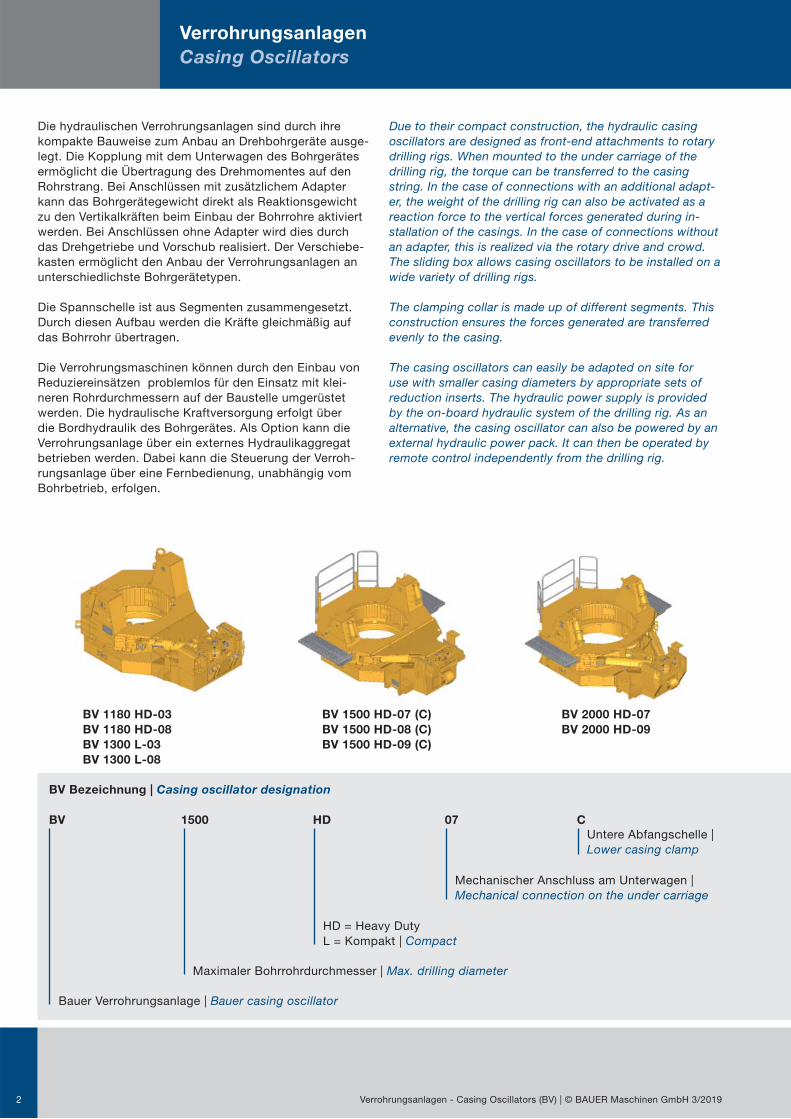
BV 1180 HD-03 BV 1500 HD-07 (C) BV 2000 HD-07
BV 1180 HD-08 BV 1500 HD-08 (C) BV 2000 HD-09
BV 1300 L-03 BV 1500 HD-09 (C)
BV 1300 L-08
Die hydraulischen Verrohrungsanlagen sind durch ihrekompakte Bauweise zum Anbau an Drehbohrgeräte ausge-legt. Die Kopplung mit dem Unterwagen des Bohrgerätes ermöglicht die Übertragung des Drehmomentes auf den Rohrstrang. Bei Anschlüssen mit zusätzlichem Adapter kann das Bohrgerätegewicht direkt als Reaktionsgewicht zu den Vertikalkräften beim Einbau der Bohrrohre aktiviert werden. Bei Anschlüssen ohne Adapter wird dies durch das Drehgetriebe und Vorschub realisiert. Der Verschiebe-kasten ermöglicht den Anbau der Verrohrungsanlagen an unterschiedlichste Bohrgerätetypen.
Die Spannschelle ist aus Segmenten zusammengesetzt.Durch diesen Aufbau werden die Kräfte gleichmäßig aufdas Bohrrohr übertragen.
Die Verrohrungsmaschinen können durch den Einbau vonReduziereinsätzen problemlos für den Einsatz mit klei-neren Rohrdurchmessern auf der Baustelle umgerüstet werden. Die hydraulische Kraftversorgung erfolgt über die Bordhydraulik des Bohrgerätes. Als Option kann die Verrohrungsanlage über ein externes Hydraulikaggregat betrieben werden. Dabei kann die Steuerung der Verroh-rungsanlage über eine Fernbedienung, unabhängig vom Bohrbetrieb, erfolgen.
Due to their compact construction, the hydraulic casing oscillators are designed as front-end attachments to rotary drilling rigs. When mounted to the under carriage of the drilling rig, the torque can be transferred to the casing string. In the case of connections with an additional adapt-er, the weight of the drilling rig can also be activated as a reaction force to the vertical forces generated during in-stallation of the casings. In the case of connections without an adapter, this is realized via the rotary drive and crowd. The sliding box allows casing oscillators to be installed on a wide variety of drilling rigs.
The clamping collar is made up of different segments. This construction ensures the forces generated are transferred evenly to the casing.
The casing oscillators can easily be adapted on site for use with smaller casing diameters by appropriate sets of reduction inserts. The hydraulic power supply is provided by the on-board hydraulic system of the drilling rig. As an alternative, the casing oscillator can also be powered by an external hydraulic power pack. It can then be operated by remote control independently from the drilling rig.
Verrohrungsanlagen
Casing Oscillators
Verrohrungsanlagen - Casing Oscillators (BV) | © BAUER Maschinen GmbH 3/2019
BV Bezeichnung | Casing oscillator designation
BV 1500 HD 07 C
Maximaler Bohrrohrdurchmesser | Max. drilling diameter
Bauer Verrohrungsanlage | Bauer casing oscillator
HD = Heavy Duty L = Kompakt | Compact
Mechanischer Anschluss am Unterwagen |Mechanical connection on the under carriage
Untere Abfangschelle | Lower casing clamp

Podeste in Kombination mit Geländer (optional)Platforms in combination with handrails (optional)
Integrierte Hydraulische Abfang-schelle (optional)Integrated hydraulic casing clamp (optional)
Reduziereinsatz für die Spann-schelle (optional)Reduction insert for clamp (optional)
3Verrohrungsanlagen - Casing Oscillators (BV) | © BAUER Maschinen GmbH 3/2019
GrundrahmenBase frame
SpannschelleClamp
TrittrostGrating
Schiebekasten (zur Horizontalverstellung)Sliding box (for horizontal adjustment)
Schiebestück Slide block
Zentrierstange Centering rod
Spannzylinder (verdeckt) Clamping cylinder (covered)
Drehzylinder Clamp rotation cylinder
HubzylinderLifting cylinder
Beschreibung der Hauptgruppen | Description of Main Components

4
Spotlights
Spotlights
Spannschelle und integrierte untere Abfangschelle
− Ein Zylinderhub von bis zu 600 mm ermöglicht ein Nachfassen mit der Spannschelle außerhalb der Rohrverbindung
− Ein innovatives Spannschellendesign ermöglicht volle Spannkraft bei minimalem Spanndruck
− Eine optionale untere Abfangschelle verringert das Verlustrisiko der Rohrgarnitur im Bohrloch beim Zieh- und Betoniervorgang
Hoher HSE Standard
− Aufstiege mit Haltebügeln für ein sicheres Auf- und Absteigen an allen vier Seiten − Optionale Geländer für das vordere Podest und die seitlichen Trittroste ermögli-
chen ein sicheres Betreten auf der Verrohrungsanlage − Steckbare Trittroste, welche zum Transport schnell und einfach abgenommen wer-
den können. Die Verstauung ist platzsparend auf der Verrohrungsanlage möglich. − Schwenk- bzw. klappbare Abdeckungen für Wartungs- bzw. Rüstarbeiten
High HSE standard
– Steps with holding brackets for safe ascent and descent on all four sides – Optional handrails for the front platform and the side gratings allow a safe
access to the casing oscillator – Steps feature a “plug-in” design; these can be removed quickly and easily for
transport purposes and stored in a practical, space-saving manner on the casing oscillator
– Swiveling and/or hinged covers for maintenance and rigging work
Clamping collar and integrated lower casing clamp
– A cylinder stroke of up to 600 mm allows the clamping collar to be moved outside the casing joint
– An innovative clamping collar design enables a full clamping force with minimum clamping pressure
– An optional lower casing clamp reduces the risk of the pipe assembly being lost in the borehole during pulling out the casing and concreting
Verrohrungsanlagen - Casing Oscillators (BV) | © BAUER Maschinen GmbH 3/2019

5
Aktivierbares Bohrgerätegewicht*
− Das Eigengewicht des Bohrgerätes kann als zusätzliche Anpresskraft mittels Adapter aktiviert werden
− Durch diese mechanische Kopplung wird auch das seitliche Kippen der Verrohrungsanlage minimiert
Anbau am Unterwagen
− Schneller An- und Abbau der Verrohrungsanlage − Verschiebekasten ermöglicht den Anbau der Verrohrungsanlage an unter-
schiedlichste Bohrgerätetypen
Attachment to the under carriage
– Rapid installation and dismantling of the casing oscillator – Sliding box allows the casing oscillator to be installed on a wide variety of
drilling rigs
Weight of the drilling rig that can be activated*
– The dead load of the drilling rig can be activated as additional contact pressure by means of adapters
– This mechanical coupling also minimizes the lateral tilt of the casing oscillator
Verrohrungsanlagen - Casing Oscillators (BV) | © BAUER Maschinen GmbH 3/2019
* abhängig vom Unterwagentyp* dependent on type of under carriage
6 Verrohrungsanlagen - Casing Oscillators (BV) | © BAUER Maschinen GmbH 3/2019
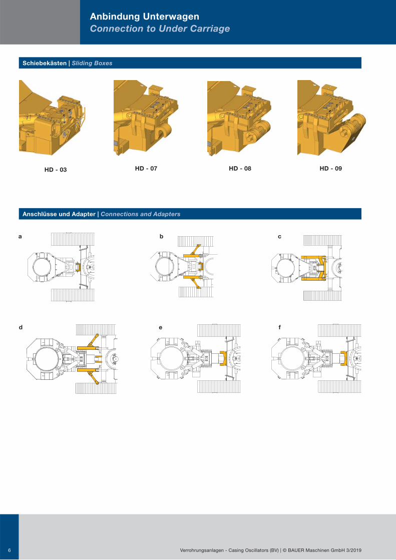
Schiebekästen | Sliding Boxes
Anschlüsse und Adapter | Connections and Adapters
HD - 03 HD - 08HD - 07 HD - 09
Anbindung Unterwagen
Connection to Under Carriage
a b c
d e f

7Verrohrungsanlagen - Casing Oscillators (BV) | © BAUER Maschinen GmbH 3/2019
Verrohrungsanlage
Casing oscillatorBV 1180 BV 1180 BV 1300 BV 1300 BV 1500 BV 1500 BV 1500 BV 2000 BV 2000
BohrgerätDrilling rig
UnterwagenUnder carriage
HD 03 HD 08 L 03 L 08HD 07
HD 07 C HD 08 HD 09 HD 07 HD 09
PremiumLine
BG 23 HUW 60 b - b - - - - - -
UW 65 a e* a e* - e* - - -
BG 28 HUW 65 a e* a e* - e* - - -
UW 80 c - c - d - - - -
BG 33 HUW 80 c - c - d - - - -
UW 100 c - c - d - - d -
BG 36 H UW 110 c - c - d - - d -
BG 33UW 80 c - c - d - - - -
UW 100 c - c - d - - d -
BG 36 UW 110 c - c - d - - d -
BG 45 UW 130 - - - - d - - d -
BG 55UW 160 - - - - d - - d -
UW 195 - - - - - - f - f
BG 72 UW 200 - - - - - - - - *
ValueLine
BG 15 H UW 50 - - - - - - - - -
BG 20 H UW 50 * * * - - - - - -
BG 26UW 65 a e* a e* - e* - - -
UW 80 b - b - d - - - -
BG 30UW 95 - e - e - e - - -
UW 100 b - b - d - - - -
BG 38
UW 110 - - - - d - - d -
UW 115 - e - e - e - - -
UW 130 - - - - d - - d -
* auf Anfrage (technische Abklärung notwendig)* on request (technical clarification is necessary)
Übersicht der Anschlüsse und Adapter an Bauer Geräten | Overview of the connections and adapters on Bauer rigs
8
Arbeitsablauf
Work Process
Verrohrungsanlagen - Casing Oscillators (BV) | © BAUER Maschinen GmbH 3/2019
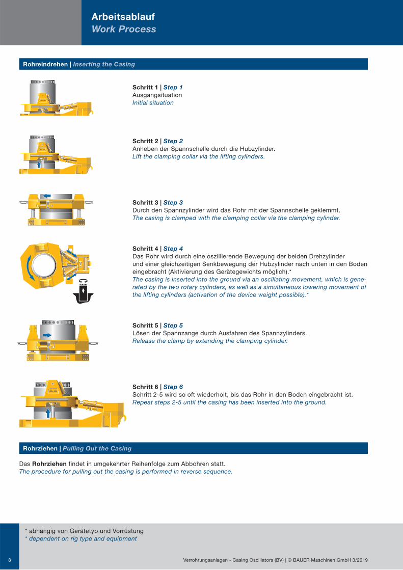
Rohreindrehen | Inserting the Casing
Das Rohrziehen findet in umgekehrter Reihenfolge zum Abbohren statt.The procedure for pulling out the casing is performed in reverse sequence.
Rohrziehen | Pulling Out the Casing
Schritt 1 | Step 1
AusgangsituationInitial situation
Schritt 2 | Step 2
Anheben der Spannschelle durch die Hubzylinder.Lift the clamping collar via the lifting cylinders.
Schritt 3 | Step 3
Durch den Spannzylinder wird das Rohr mit der Spannschelle geklemmt.The casing is clamped with the clamping collar via the clamping cylinder.
Schritt 4 | Step 4
Das Rohr wird durch eine oszillierende Bewegung der beiden Drehzylinder und einer gleichzeitigen Senkbewegung der Hubzylinder nach unten in den Boden eingebracht (Aktivierung des Gerätegewichts möglich).*The casing is inserted into the ground via an oscillating movement, which is gene-rated by the two rotary cylinders, as well as a simultaneous lowering movement of the lifting cylinders (activation of the device weight possible).*
Schritt 5 | Step 5
Lösen der Spannzange durch Ausfahren des Spannzylinders.Release the clamp by extending the clamping cylinder.
Schritt 6 | Step 6
Schritt 2-5 wird so oft wiederholt, bis das Rohr in den Boden eingebracht ist.Repeat steps 2-5 until the casing has been inserted into the ground.
* abhängig von Gerätetyp und Vorrüstung* dependent on rig type and equipment

Zubehör für die Verrohrungsanlage
Accessories for the Casing Oscillator
9Verrohrungsanlagen - Casing Oscillators (BV) | © BAUER Maschinen GmbH 3/2019
Reduziereinsätze | Reduction Inserts
Versorgung mit einem Bauer Hydraulikaggregat | Supply Provided via a Bauer Hydraulic Power Pack
Verrohrungsanlage | Casing oscillator BV 1180 BV 1300 BV 1500 BV 1500 C BV 2000
Rohrdurchmesser | Casing diameter (mm) * 600 - 1.080 620 - 1.180 600 - 1.420 880 - 1.300 1.000 - 1.925
– Betrieb einer Verrohrungsanlage ohne hydraulische Nachrüstung des Bohrgerätes – Der Bohrgerätefahrer wird dadurch entlastet, dass eine zweite Person die Verrohrungsanlage über eine Kabel- oder
Funkfernbedienung steuert. – Unabhängiges Arbeiten von Verrohrungsanlage und Bohrgerät möglich
– Operation of a casing oscillator without the need for hydraulic retrofitting of the drilling rig – Relief of the strain on the drilling rig operator as a result of the casing oscillator being operated by a second person via
a wired remote control or optional radio remote control – Independent operation of the casing oscillator and drilling rig possible
* weitere Reduziereinsätze auf Anfrage* other reduction inserts on request

10
Technische Spezifikation
Technical Specifications
Verrohrungsanlagen - Casing Oscillators (BV) | © BAUER Maschinen GmbH 3/2019
DE
D*
B
F
F*
G
B*
Verrohrungsanlage
Casing oscillatorBV 1180 BV 1180 BV 1300
HD 03 HD 08 L 03
AMax. RohrdurchmesserMax. casing diameter
mm 1.180 1.180 1.300
Max. Betriebsdruck Max. operating pressure
bar 320 320 320
Drehmoment bei 320 barTorque at 320 bar
kNm 1.075 1.075 1.140
Hub | Stroke mm 500 500 500
Hubkraft bei 320 barLifting force at 320 bar
kN 1.450 1.450 1.450
Spannkraft - Spannzylinder (250 bar)Clamping force - clamping cylinder (250 bar)
kN 590 590 590
Spannkraft - Spannzylinder (320 bar)Clamping force - clamping cylinder (320 bar)
kN 754 754 754
Drehwinkel | Swing angle ° 26 26 25
Rohrdrehung bei Nenndurchmesser Casing rotation at nominal diameter
mm 267 267 283
Gewicht (ca.) | Weight (approx.) kg 7.500 7.800 8.000
BGesamtlänge ohne Begehung (ca.)Total length without platform (approx.)
mm 3.345 3.460 3.505
B*Gesamtlänge mit Begehung (ca.)Total length with platform (approx.)
mm - - -
C Breite | Width mm 2.030 2.030 2.300
C*Breite mit Trittrost (ca.)Width with grating (approx.)
mm - - -
D Höhe | Height mm 1.480 1.480 1.480
D* Höhe mit Geländer (ca.)Height with handrails (approx.)
mm - - -
EHöhe Boden - Oberkante SchelleHeight between ground and top edge of clamp
mm 850 850 850
F Vorderkante Schelle | Front edge of clamp mm 1.000 1.000 1.100
F *Vorderkante Podest - BohrachseFront edge of platform - drill axis
mm - - -
GAbstand Anlenkung - BohrachseDistance link - drill axis
mm 2.275 2.275 2.335
Relativverschiebung SchiebekastenRelative movement of sliding box
mm 530 530 530
Abfangschelle | Casing clamp - - -

11Verrohrungsanlagen - Casing Oscillators (BV) | © BAUER Maschinen GmbH 3/2019
ACC*
BV 1300 BV 1500 BV 1500 BV 1500 BV 1500 BV 2000 BV 2000
L 08 HD 07 HD 07 C HD 08 HD 09 HD 07 HD 09
1.300 1.500 1.500 1.500 1.500 2.000 2.000
320 320 320 320 320 320 320
1.140 2.200 2.200 2.200 2.200 2.965 2.965
500 520 520 520 520 600 600
1.450 2.010 2.010 2.010 2.010 2.430 2.430
590 755 755 755 755 880 880
754 967 967 967 967 1.125 1.125
25 25 25 25 25 25 25
283 327 327 327 327 436 436
8.300 12.500 13.500 12.800 13.200 20.200 20.900
3.620 4.075 4.075 4.110 4.458 4.655 5.053
- 4.135 4.135 4.170 4.522 4.758 5.157
2.300 2.715 2.715 2.715 2.715 3.200 3.200
- 3.784 3.784 3.784 3.784 4.284 4.284
1.480 1.603 1.603 1.603 1.603 1.960 1.960
- 2.014 2.014 2.014 2.014 2.215 2.215
850 920 920 920 920 1.115 1.115
1.100 1.350 1.350 1.350 1.350 1.400 1.400
- 1.410 1.410 1.410 1.410 1.694 1.694
2.335 2.565 2.565 2.600 2.948 2.905 3.288
530 690 690 690 690 690 690
- - - -

24/724/7
Global Network Service
Equipment Training
BAUER Maschinen GmbH BAUER-Straße 1 86529 Schrobenhausen Deutschland Tel. +49 8252 97-0 [email protected] www.bauer.de
International Service Hotline+800 1000 1200* (freecall)+49 8252 [email protected]
* Where available
905.519.1+2 3/2019
BG
Acc
esso
ry
Konstruktionsentwicklungen und Prozessverbesserungen können Aktualisierungen und Änderungen von Spezifikation und Materialien ohne vorherige Ankündigung oder Haftung erforderlich machen.Die Abbildungen enthalten möglicherweise optionale Ausstattung und zeigen nicht alle möglichen Konfigurationen. Diese Angaben und die technischen Daten haben ausschließlich Informationscharakter. Irrtum und Druckfehler vorbehalten.
Design developments and process improvements may require the specification and materials to be updated and changed without prior notice or liability. Illustrations may include optional equipment and not show all possible configurations.These and the technical data are provided as indicative information only, with any errors and misprints reserved.