Embed Size (px)
Citation preview

Butyl Sepharose 4 Fast Flow Octyl Sepharose 4 Fast Flow
Hydrophobic interaction resin
Instructions for UseButyl Sepharose™ 4 Fast Flow and Octyl Sepharose 4 Fast Flow form part ofthe Cytiva resin range for hydrophobic interaction chromatography (HIC).
These instructions contain information about resin characteristics, columnpacking, and maintenance.
cytiva.com 71500240 AF

Table of Contents
1 Introduction ............................................................................................. 3
2 Column packing guidelines ................................................................ 7
3 Evaluation of packed column ............................................................ 22
4 Maintenance ............................................................................................ 25
5 Reference information ......................................................................... 28
Read these instructions carefully before using the products.
Safety
For use and handling of the products in a safe way, refer to theSafety Data Sheets.
2 71500240 AF

1 IntroductionBioProcess™ resins
Butyl Sepharose 4 Fast Flow and Octyl Sepharose 4 Fast Flowbelong to the BioProcess resins. BioProcess chromatographyresins are developed and supported for production-scalechromatography. BioProcess resins are produced withvalidated methods and are tested to meet manufacturingrequirements. Secure ordering and delivery routines give areliable supply of resins for production-scale. RegulatorySupport Files (RSF) are available to assist process validationand submissions to regulatory authorities. BioProcess resinscover all purification steps from capture to polishing.
Description
The base matrix, Sepharose 4 Fast Flow, is a cross-linked, 4%agarose derivative with excellent kinetics, making them idealfor process scale applications, particularly during initialcapture and intermediate stages of a separation processwhen high flow rates are required.
The high physical and chemical stabilities of the matrixprevent bed compression and formation of fines, and allowefficient maintenance procedures for increased resin life time.A typical pressure/flow curve is shown below for ButylSepharose 4 Fast Flow.
71500240 AF 3

0 200
Pressure (bar)
Flow velocity (cm/h)
300
400
500
0.2 0.4 0.6 0.8 1.0 1.2
Fig 1. Typical pressure/flow curve for Butyl Sepharose 4 Fast Flow in an XK 50/30column, bed height 15 cm; mobile phase 0.1 M NaCl.
Table 1. Characteristics of Butyl Sepharose 4 Fast Flow.
Matrix Cross-linked agarose, 4%, spherical
Type of ligand Butyl: R-O-CH2-CH(OH)-CH2-O-(CH2)3-CH3
Particle Size, d50V 1 ~ 90 µm
Ligand concentration ~ 40 µmol Butyl/mL resin
pH stability, operational 2
pH stability, CIP 3
3 to 13
2 to 14
Chemical Stability Stable to commonly used aqueous buffers,1 mM HCl, 1.0 M NaOH4, 30% isopropanol,70% ethanol, 6 M guanidine hydrochloride
Autoclavability 20 min at 121°C in distilled water pH 7, 5cycles
4 71500240 AF

Pressure/flow characteristics 150 to 250 cm/h at < 0.1 MPa in a XK 50/60column with 5 cm diameter and 25 cm bedheight (at 20°C using buffers with the sameviscosity as water).5 6
Operating temperature 4°C to 40°C
Delivery conditions 20% ethanol1 Median particle size of the cumulative volume distribution.2 pH range where resin can be operated without significant change in function.3 pH range where resin can be subjected to cleaning- or sanitization-in-place without
significant change in function.4 1.0 M NaOH must only be used for cleaning purposes.5 The pressure/flow characteristics describes the relationship between pressure and flow
under the set circumstances. The pressure given shall not be taken as the maximumpressure of the resin.
6 Pressure/flow test performed on the base matrix.
Table 2. Characteristics of Octyl Sepharose 4 Fast Flow
Matrix Cross-linked agarose, 4%, spherical
Type of ligand Octyl: R-O-CH2-CH(OH)-CH2-O-(CH2)7-CH3
Particle Size, d50V 1 ~ 90 µm
Ligand concentration ~ 5 µmol Octyl/mL resin
pH stability, operational 2
pH stability, CIP 3
3 to 13
2 to 14
Chemical Stability Stable to commonly used aqueous buffers,1 mM HCl, 1.0 M NaOH4, 30% isopropanol,70% ethanol, 6 M guanidine hydrochloride
Autoclavability 20 min at 121°C in distilled water pH 7, 5cycles
Pressure/flow characteristics 150 to 250 cm/h at < 0.1 MPa in a XK 50/60column with 5 cm diameter and 25 cm bedheight (at 20°C using buffers with the sameviscosity as water).5 6
Operating temperature 4°C to 40°C
Delivery conditions 20% ethanol1 Median particle size of the cumulative volume distribution.2 pH range where resin can be operated without significant change in function.3 pH range where resin can be subjected to cleaning- or sanitization-in-place without
significant change in function.
71500240 AF 5

4 1.0 M NaOH must only be used for cleaning purposes.5 The pressure/flow characteristics describes the relationship between pressure and flow
under the set circumstances. The pressure given shall not be taken as the maximumpressure of the resin.
6 Pressure/flow test performed on the base matrix.
Method design and optimization
The main purpose of optimizing a chromatographic step is toreach the predefined purity level with highest possibleproduct recovery by choosing the most suitable combinationof the critical chromatographic parameters. In processchromatography, in contrast to analytical or small-scalepreparative chromatography, this has to be accomplished asquickly and economically as possible. This means finding theconditions that give the highest possible productivity andprocess economy.
Recommendations for optimizing the critical operationalparameters which affect the maximum utilization of a HICstep can be found in the handbook (11001269), available fromyour local Cytiva office.
Resin screening
Table 3, on page 6 shows the kits that help with screeningand selection of resin.
Table 3.
Screening kit Description
PreDictor™ HIC Screening
High Hydrophobicity
Phenyl Sepharose 6 Fast Flow (low sub)
Capto™ Butyl
Phenyl Sepharose Fast Flow (high sub)
Capto Phenyl (high sub)
6 71500240 AF
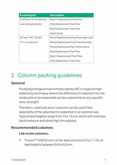
Screening kit Description
PreDictor HIC Screening
Low Hydrophobicity
Butyl-S Sepharose 6 Fast Flow
Octyl Sepharose 4 Fast Flow
Butyl Sepharose 4 Fast Flow
Capto Octyl
HiTrap™ HIC Test Kit
7×1 mL columns
Phenyl Sepharose 6 Fast Flow (high sub)
Phenyl Sepharose 6 Fast Flow (low sub)
Phenyl Sepharose High Performance
Butyl Sepharose 4 Fast Flow
Butyl-S Sepharose 6 Fast Flow
Octyl Sepharose 4 Fast Flow
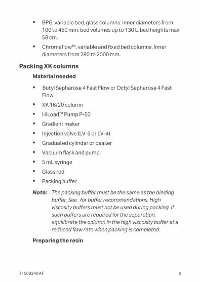
2 Column packing guidelinesGeneral
Purifying biological macromolecules by HIC is a typical highselectivity technique where the difference in retention for themolecules to be separated can be substantial at any specificionic strength.
Therefore, relatively short columns can be used if theselectivity of the adsorbent is exploited in an optimal way.Typical bed heights range from 3 to 15 cm, which will minimizeback pressure and allow high throughput.
Recommended columns
Lab-scale columns:
• Tricorn™ 5/50 (5 mm i.d.) for bed volumes 0.2 to 1.1 mL atbed heights between 0.8 to 5.6 cm.
71500240 AF 7

• Tricorn 5/100 (5 mm i.d.) for bed volumes 1.2 to 2.1 mL atbed heights between 5.8 to 10.6 cm.
• Tricorn 5/150 (5 mm i.d.) for bed volumes 2.1 to 3.1 mL atbed heights between 10.8 to 15.6 cm.
• Tricorn 10/50 (10 mm i.d.) for bed volumes up to 4.4 mL atbed heights up to 5.6 cm.
• Tricorn 10/100 (10 mm i.d.) for bed volumes 3.6 to 8.4 mLat bed heights between 4.6 to 10.6 cm.
• Tricorn 10/150 (10 mm i.d.) for bed volumes 7.6 to 12.6 mLat bed heights between 9.6 to 15.6 cm.
• XK 16/20 (16 mm i.d.) for bed volumes up to up to 31 mL atbed heights up to 15.5 cm.
• XK 26/20 (26 mm i.d.) for bed volumes up to 66 mL at bedheights up to 12.5 cm.
• XK 50/20 (50 mm i.d.) for bed volumes up to 274 mL at bedheights up to 14 cm.
• XK 50/30 (50 mm i.d.) for bed volumes up to 559 mL at bedheights up to 28 cm.
• HiScale™ 50/20 (50 mm i.d.) for bed volumes up to 393 mLat bed heights up to 20 cm.
• HiScale 50/40 (50 mm i.d.) for bed volumes 274 to 785 mLat bed heights between 14 to 40 cm.
Large-scale columns:
• AxiChrom™, i.d. 50 to 200 mm, bed volumes up to 16.7 L,bed heights up to 50 cm
• AxiChrom, i.d. 300 to 1600 mm, bed volumes up to 1005 L,bed heights up to 50 cm
8 71500240 AF
• BPG, variable bed, glass columns: inner diameters from100 to 450 mm, bed volumes up to 130 L, bed heights max58 cm.
• Chromaflow™, variable and fixed bed columns. Innerdiameters from 280 to 2000 mm.
Packing XK columns
Material needed
• Butyl Sepharose 4 Fast Flow or Octyl Sepharose 4 FastFlow
• XK 16/20 column
• HiLoad™ Pump P-50
• Gradient maker
• Injection valve (LV-3 or LV-4)
• Graduated cylinder or beaker
• Vacuum flask and pump
• 5 mL syringe
• Glass rod
• Packing buffer
Note: The packing buffer must be the same as the bindingbuffer. See , for buffer recommendations. Highviscosity buffers must not be used during packing. Ifsuch buffers are required for the separation,equilibrate the column in the high viscosity buffer at areduced flow rate when packing is completed.
Preparing the resin
71500240 AF 9

Step Action
1 Equilibrate all material to room temperature.
2 Sepharose Fast Flow HIC resins are suppliedpreswollen in 20% ethanol. Decant the ethanolsolution and replace it with packing buffer to a totalvolume of 32.5 mL (75% settled resin: 25% buffer).
3 De-gas the slurry under vacuum.
Assembling the column
Details of the column parts can be found in the instructionssupplied with the column. Before packing, make sure that allparts, particularly the nets, net fasteners and glass tube, areclean and intact.
Step Action
1 Connect the column bottom end piece to a pump orsyringe.
2 Submerge the end piece in buffer and fill it using thepump or syringe. Make sure that there are no airbubbles trapped under the net.
3 Close the tubing with a stopper and attach the endpiece on the column.
4 Flush the column with buffer, leaving a few mL at thebottom.
5 Attach the column vertically on a laboratory stand.
Packing the column
10 71500240 AF

These instructions are based for packing Sepharose Fast FlowHIC resin in the recommended XK 16/20 Column. To modifythese instructions for columns of different dimensions, referto Appendix A.
Step Action
1 Pour the resin slurry into the column in one continuousmotion. Pouring down a glass rod held against the wallof the column helps prevent the introduction of airbubbles. Fill the remainder of the column with buffer.
2 Wet the column adapter by submerging the plungerend in buffer, and drawing buffer through with asyringe or pump. Make sure that all bubbles have beenremoved. Disconnect the pump or syringe.
3 Insert the adapter into the top of the column at anangle, taking care not to trap air under the net. Tightenthe adapter O-ring to give a sliding seal on the columnwall.
4 Fit a syringe barrel to the sample application valve andconnect the valve between the adapter and the pump.With the valve in the sample application position, slidethe adapter down into the column. This will displace allair in the tubing as far as the sample application valve.Switch the valve a few times to remove any trappedbubbles. Continue inserting the adapter until itreaches the resin slurry. Tighten the O-ring and lockthe adapter in position.
71500240 AF 11

Step Action
5 Open the bottom outlet of the column and start thepump.
Pack the resin at a flow rate of 12 to 14 mL/min untilthe bed height is constant (normally 4 to 5 minutes).
6 Stop the pump, close the column outlet, loosen theadapter O-ring to give a sliding seal and reposition theadapter on the surface of the resin bed. Press theadapter into the surface of the resin an additional 1 to2 mm.
7 Lock the adapter in position, open the column outletand start the pump at the column packing flow rate.
If the bed continues to pack, repeat step 5. When the resin bedis stable, the column is packed, equilibrated and ready for use.
Equilibration
To equilibrate, pump approximately 100 mL of start bufferthrough the column at a flow rate of 2.5 mL/min. The column isfully equilibrated when the pH and/or conductivity of theeffluent is the same as the start buffer.
Sample preparation
The amount of sample that can be applied to the columndiffers considerably, depending on the ligand concentration ofthe resin, the nature of the sample, and on start bufferconditions. See Table 1, on page 4 and Table 2, on page 5 forcapacity guidelines.
12 71500240 AF

High ligand concentration does not necessarily correspond tohigh capacity for adsorption of protein, but a high ligandconcentration can encourage multipoint attachment ofproteins which otherwise can have difficulty adsorbing tolower ligand concentrations. A moderate ligand concentrationallows selective binding of the protein of interest byadjustment of the binding buffer concentration.
The sample must be dissolved in start buffer. Alternatively thesample can be transferred to start buffer by dialysis or bybuffer exchange using a HiTrap Desalting or a PD-10 Desaltingcolumn. The viscosity of the sample must not exceed that ofthe buffer. For normal aqueous buffer systems, thiscorresponds to a protein concentration of approximately 50mg/mL.
Before application the sample must be centrifuged or filteredthrough a 0.45 μm filter to remove any particulate matter.
Operating flow rates
The flow rate used for sample binding and subsequent elutionwill depend on the degree of resolution required, but isnormally within the range of 2.5 to 5 mL/min. A lower flow rategives a better resolution.
Binding
The binding of proteins to hydrophobic resins is influenced by:
• the structure of the ligand (for example carbon chain or anaromatic ligand)
• the ligand concentration
• the ionic strength of the buffer
• the salting-out effect (see The Hofmeister series below)
• the temperature
71500240 AF 13

Salts that cause salting-out (for example ammoniumsulphate) also promote binding to hydrophobic ligands. Thecolumn is equilibrated and the sample is applied in a solutionof high ionic strength. A typical starting buffer is 1.7 M(NH4)2SO4, which is just below the concentration employed forsalting out proteins.
Hydrophobic interactions are weaker at lower temperatures.This must be taken into account if chromatography isperformed in a cold room.
Elution
Bound proteins are eluted by reducing the strength of thehydrophobic interaction. This can be done by:
• reducing the concentration of salting-out ions in thebuffer with a decreasing salt gradient (linear or step)
• increasing the concentration of chaotropic ions in thebuffer with an increasing gradient (linear or step)
• eluting with a polarity-reducing organic solvent (forexample ethylene glycol) added to the buffer
• eluting with detergent added to the buffer
The Hofmeister series
← Increasing precipitation ("salting-out") effect
Anions: PO4 3- SO4 2- CH3COO- Cl- Br- NO3- ClO4- I- SCN-
Cations: NH4+ Rb+ K+ Na+ Cs+ Li+ Mg2+ Ba2+
Increasing chaotropic ("salting-in") effect →
Increasing the salting-out effect strengthens hydrophobicinteractions; increasing the chaotropic effect weakenshydrophobic interactions.
14 71500240 AF

A suggested starting gradient is a linear gradient from 0 to100% B with:
Buffer A: 50 mM phosphate buffer, pH 7.0 + 1.7 M (NH4)2SO4 1
Buffer B: 50 mM phosphate buffer, pH 7.0
Packing process-scale columns
General packing procedures
Columns can be packed in different ways depending on thetype of column and equipment used. Always read and followthe relevant column instruction manual carefully. Sepharose 4Fast Flow based resins are easy to pack since their rigidityallows the use of high flow velocities, see Figure 1, on page 4.
General parameters for large-scale packing:
• Preferred packing solution: 10% to 20% ethanol
• Resin slurry concentration: 50%
• Packing pressure: 0.1 MPa (1 bar, 14.5 psi)
• Packing flow velocity: 200 to 300 cm/h
Two types of packing methods are described:
• Pressure packing (for columns with adapters)
• Chromaflow packing
How well the column is packed will have a major effect on theresult of the separation. It is therefore very important to packand test the column according to the followingrecommendations.
1 When working with proteins which have a tendency toaggregate, start with a lower (NH4)2SO4 concentrationto avoid protein precipitation.
71500240 AF 15

Begin the packing procedure by determining the optimalpacking flow rate. Guidelines are given below for determiningthe optimal packing flow rates for columns with adapters andfixed bed heights.
Determining optimal packing flow rates
The optimal packing flow rate is dependent on column sizeand type, resin volume, packing solution, and temperature.The optimal packing flow rate must therefore be determinedempirically for each individual system.
To determine the optimal packing flow rate, proceed asfollows:
Step Action
1 Calculate the amount of resin needed for the slurry(this is especially important for columns with fixed bedheights). The quantity of resin required per liter packedvolume is approximately 1.15 L sedimented resin.
2 Prepare the column exactly as for column packing.
3 Begin packing the resin at a low flow velocity (30 cm/h).
4 Increase the pressure in increments and record theflow rate when the pressure has stabilized. Do notexceed the maximum pressure of the column, or themaximum flow rate for the resin.
5 The maximum flow rate is reached when the pressure/flow curve levels off or the maximum pressure of thecolumn is reached. Stop the packing and do not exceedthis flow rate. The optimal packing flow rate/pressureis 70% to 100% of the maximum flow rate/pressure.
16 71500240 AF

Step Action
6 Plot the pressure/flow curve as in Figure 1, on page 4and determine the optimal packing flow rate.
The operational flow rate/pressure must be < 70% of thepacking flow rate/pressure.
Packing AxiChrom columns
AxiChrom columns are packed using mechanical axialcompression packing. For more information regarding theAxiChrom columns and packing procedures see belowdocumentation:
• AxiChrom Columns (28929041)
• AxiChrom 50, 70 and 100 columns, Operating instructions(28933108)
• AxiChrom 140 and 200 columns, Operating instructions(28943123)
• AxiChrom 300-1600 columns, Operating instructions(29065430)
Pressure packing of BPG columns
BPG glass columns are supplied with a movable adapter. Theyare packed by conventional pressure packing by pumping thepacking solution through the chromatographic bed at aconstant flow rate (or back pressure).
Step Action
1 Pour some water (or packing solution) into the column.Make sure that there is no air trapped under thebottom net. Leave about 2 cm of liquid in the column.
71500240 AF 17
Step Action
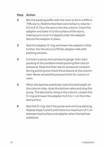
2 Mix the packing buffer with the resin to form a 50% to70% slurry. (Sedimented bed volume/slurry volume =0.5 to 0.7). Pour the slurry into the column. Insert theadapter and lower it to the surface of the slurry,making sure no air is trapped under the adapter.Secure the adapter in place.
3 Seal the adapter O-ring and lower the adapter a littlefurther into the slurry to fill the adapter inlet withpacking solution.
4 Connect a pump and a pressure gauge, then startpacking at the predetermined packing flow rate (orpressure). Keep the flow rate (or pressure) constantduring packing and check the pressure at the columninlet. Never exceed the pressure limit for column orresin.
5 When the bed has stabilized, mark the bed height onthe column tube, close the bottom valve and stop thepump. The bed starts rising in the column. Loosen theO-ring and lower the adapter to 0.5 to 1 cm from thebed surface.
6 Seal the O-ring, start the pump and continue packing.Repeat steps 5 and 6 until there is a maximum of 1 cmbetween bed surface and adapter when the bed hasstabilized.
18 71500240 AF

Step Action
7 Close the bottom valve, stop the pump, disconnect thecolumn inlet and push the adapter down toapproximately 3 mm below the mark on the columntube without loosening the adapter O-ring. Thepacking solution will flush the adapter inlet. Removeany trapped air by pumping liquid from the bottom(after the inlet tubing and the bottom valve have beenproperly filled).
Packing Chromaflow columns
Prepare the column for packing as described in the Operatinginstructions.
This section describes how to pack from the top, or frombelow.
To pack from the top, follow these instructions:
Step Action
1 Set the top nozzle to the pack position (mid-position).
2 Fully retract the bottom nozzle (run position).
3 Make sure that the top mobile phase is closed.
4 Open the bottom mobile phase.
71500240 AF 19

Step Action
5 Open Inlet (C) and start the packing pump. Adjust theflow to achieve the required packing conditions for theselected resin. Monitor column pressure and the outletflow rate in order to record column packingparameters. Remember to stir the resin slurry duringpacking to prevent it from settling.
6 Continue pumping until the column is fully packed andthe pump stalls due to buildup of resin in its pipelines.Turn off the packing pump.
7 Fully retract the top nozzle to its run position. CloseOutlet (C). Open Inlet (B) from the water/buffer tankand open Outlet (D). The pump must now be restartedto rinse the top slurry lines. If the nozzle is full of liquidwhen in the packing position, make sure that the wasteslurry outlet is open before retracting the nozzle.
8 To clean-in-place, exchange the buffer tank for wash/buffer tank containing cleaning solution.
To pack from below, carry out the same procedure for theconnections and flow path via the bottom nozzle. The columnis now ready to equilibrate and test.
Note: It is also possible to use a slightly different packingmethod where the amount of resin is packed into thecolumn causing compression of the bed. When allresin has entered the column the pump is stopped, thetop nozzle is retracted, the bottom mobile phase valveclosed, and the resin is allowed to decompress withinthe column.
20 71500240 AF

The illustration below shows the principles of operatingChromaflow columns.
Packing position
The top nozzle isextended part of the way(mid position) into thecolumn. The bottomnozzle is fully retracted.
Slurry enters the columnvia the top nozzle andexcess liquid exits via thebottom mobile phaseoutlet. After packing, theslurry lines are isolatedfrom the mobile phaseand can be cleanedindependently from therest of the column.
Running position
The bottom and topnozzles are retracted.Mobile phase enters thecolumn directly into anannulus, immediatelybehind the bed support.The annulus is cutthrough at an angle tomake sure that linearflow rate is kept constantduring distribution of themobile phase across thebed.
71500240 AF 21
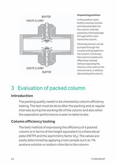
Unpacking position
In this position, bothbottom and top nozzlesare fully extended intothe column, therebyexposing a third passagethrough which resinleaves the column.
Cleaning solution can bepumped through thenozzles and sprayed intothe column. In this waythe column is easily andeffectively cleanedwithout exposing theinterior or the resin to theenvironment, or withoutdismantling the column.
3 Evaluation of packed columnIntroduction
The packing quality needs to be checked by column efficiencytesting. The test must be done after the packing and at regularintervals during the working life of the column and also whenthe separation performance is seen to deteriorate.
Column efficiency testing
The best method of expressing the efficiency of a packedcolumn is in terms of the height equivalent to a theoreticalplate (HETP) and the asymmetry factor (As). The values areeasily determined by applying a test sample such as 1%acetone solution or sodium chloride to the column.
22 71500240 AF

Note: Use a concentration of 0.8 M NaCl in water as sampleand 0.4 M NaCl in water as eluent.
The calculated plate number is depended on the testconditions and must only be used as a reference value. It isimportant that the test conditions and the equipment are thesame so that the results are comparable.
Note: Changing the solute, solvent, eluent, sample volume,flow velocity, liquid pathway, temperature,chromatography system, etc., influence the results.
For more information about column efficiency testing, consultthe application note (28937207).
For optimal column efficiency results, the sample volumemust be approximately 1% of the column volume and the flowvelocity 30 cm/h. If an acceptance limit is defined in relation tocolumn performance, the column plate number can be usedas one of the acceptance criteria for the column use.
Sample volume and flow velocity
For optimal column efficiency results, the sample volumemust be approximately 1% of the column volume and the flowvelocity 30 cm/h. If an acceptance limit is defined in relation tocolumn performance, the column plate number can be usedas one of the acceptance criteria for the column use.
Method for measuring HETP and As
Calculate HETP and AS from the UV curve (or conductivitycurve) as follows:
LN
HETP =L = bed height (cm)
N = number of theoretical plates
71500240 AF 23

VR
WhN = 5.54 ×
2
VR = volume eluted from the start ofsample application to the peakmaximum.
Wh = peak width measured as thewidth of the recorded peak at half ofthe peak height.
VR and Wh are in the same units.
The concept of reduced plate height is often used forcomparing column performance.
The reduced plate height, h, is calculated as follows:
HETPd50v
h = d50V = Median particle size of thecumulative volume distribution (cm)
As a guideline, a value of < 3 is very good.
The peak must be symmetrical, and the asymmetry factor asclose to 1 as possible. A typical acceptable range could be 0.8< AS < 1.5.
A change in the shape of the peak is usually the first indicationof bed deterioration due to excessive use.
Peak asymmetry factor calculation:
ba
As =
a = ascending part of the peak width at10% of peak height
b = descending part of the peak widthat 10% of peak height
The Figure below shows a UV trace for acetone in a typical testchromatogram from which the HETP and As values arecalculated.
24 71500240 AF

VR
Wh
50%
10%
Volume
a b
Absorbance
Fig 2. A typical test chromatogram showing the parameters used for HETP andAs calculations.
4 MaintenanceRegeneration
For best performance from the resins, bound substances mustbe washed from the column after each chromatographiccycle.
Wash with 2 bed volumes of water, followed by 2 to 3 bedvolumes of starting buffer.
To prevent a slow build up of contaminants on the columnover time, it is possible that more rigorous cleaning protocolshave to be applied on a regular basis.
71500240 AF 25

Cleaning-in-place (CIP)
Cleaning-in-place (CIP) is the removal of very tightly bound,precipitated or denatured substances from the purificationsystem generated in previous purification cycles. If suchcontaminants accumulate on the column, they can affect thechromatographic properties of the column. If the fouling issevere, it can also block the column, increasing back pressureand reducing flow rate.
The following are suggested methods to remove stronglybound hydrophobic proteins, lipoproteins, and lipids:
• Wash the column with 4 to 10 bed volumes of up to 70%ethanol or 30% isopropanol followed by 3 to 4 bedvolumes of water. Apply gradients to avoid air bubbleformation when using high concentrations of organicsolvents.
• Alternatively, wash the column with 1 to 2 bed volumes of0.5% nonionic detergent followed by 5 bed volumes of70% ethanol to remove the detergent, and 3 to 4 bedvolumes of water.
CAUTION70% ethanol can require the use ofexplosion-proof areas and equipment.
To remove other contaminants the following method issuggested:
• Wash the column with 4 bed volumes of 0.5 to 1.0 M NaOHat 40 cm/h, followed by 2 to 3 bed volumes of water.
26 71500240 AF

The CIP protocols given above must be used as guidelineswhen formulating a cleaning protocol specific for the rawmaterial used. The frequency of CIP will depend on the rawmaterial applied to the column, but it is recommended to use aCIP procedure at least every 5 cycles during normal use.Depending on the nature of the contaminants, it can benecessary to use a combination of different protocols. Iffouling is severe, it can be necessary to further optimize theprotocols. During CIP flow direction through the column mustbe reversed.
Sanitization
Sanitization is the reduction of microbial contamination in thecolumn and related equipment to an acceptable minimum. Aspecific sanitization protocol must be designed for eachprocess according to the type of contaminants present. Thefollowing is a recommended protocol.
Wash the column with 0.5 to 1.0 M NaOH at a flow velocity ofapproximately 40 cm/h, contact time 30 to 60 minutes.
Sterilization
To sterilize Butyl Sepharose 4 Fast Flow or Octyl Sepharose 4Fast Flow, dismantle the column and autoclave the resin for20 minutes at 121°C.
Storage
Store Butyl Sepharose 4 Fast Flow and Octyl Sepharose 4 FastFlow in 20% ethanol at 4°C to 30°C, to avoid microbiologicalgrowth.
71500240 AF 27

5 Reference informationThis chapter lists product codes for products, handbooks, anddata files that relate to Butyl Sepharose 4 Fast Flow and OctylSepharose 4 Fast Flow. For further information, see cytiva.com
Product Quantity Product code
Butyl Sepharose 4 Fast Flow 25 mL 17098010
200 mL 17098001
500 mL 17098002
5 L 17098004
10 L 17098005
Octyl Sepharose 4 Fast Flow 25 mL 17094610
200 mL 17094602
1 L 17094603
5 L 17094604
PreDictor Screening High Hydrophobicity 6 µL 28992392
PreDictor Screening High Hydrophobicity 50 µL 28992397
PreDictor Screening Low Hydrophobicity 6 µL 28992395
PreDictor Screening High Hydrophobicity 50 µL 28992398
HiTrap HIC Test Kit 7 x 1 mL 28411007
HiTrap Butyl FF 5 x 1 mL 17135701
5 x 5 mL 17519701
HiTrap Octyl FF 5 x 1 mL 17135901
5 x 5 mL 17519601
HiPrep 16/10 Butyl FF 20 mL 17509601
HiPrep 16/10 Octyl FF 20 mL 17509701
Tricorn 5/50 1 28406409
Tricorn 5/100 1 28406410
Tricorn 5/150 1 28406411
Tricorn 10/50 1 28406414
Tricorn 10/100 1 28406415
28 71500240 AF

Product Quantity Product code
Tricorn 10/150 1 28406416
XK 16/20 1 18877301
XK 26/20 1 18100072
XK 50/20 1 28988952
HiScale 50/20 1 28964445
HiScale 50/40 1 28964444
Related literature Product code
Handbook Hydrophobic Interaction Chromatography andReversed Phase Chromatography: Principlesand Methods
11001269
Data files HiTrap HIC Selection Kit 17114321
HiScreen Prepacked Columns 28930581
Butyl Sepharose 4 Fast Flow 18102017
BPG 100, 140, 200, 300, 450 18111523
Chromaflow 18113892
AxiChrom Columns 28929041
Media Wand Media handling Unit 28923101
Instructions Predictable scale-up through column designand robust packing methodology
28949052
Constant Flow Packing method 29001795
Pack-in-place packing procedure 29001797
The complete range of Sepharose Fast Flow resins includesother HIC resins as well as resins for ion exchange and affinitychromatography. Further information is available uponrequest.
71500240 AF 29

Appendix AConverting to columns of different dimensions
Flow rates
Flow rates quoted in this instruction are for an XK 16/20column. To convert flow rates for columns of differentdimensions:
1. Divide the volumetric flow rates (mL/min) quoted by afactor of 2 (the cross-sectional area in cm2 of the XK16/20) to give the flow velocity in cm/min.
2. Maintain the same flow velocity and calculate the newvolumetric flow rate according to the cross-sectional areaof the specific column to be used
Volumetric flow rateColumn cross-sectional area________________________Flow velocity =
Volumes
Volumes (buffers, gradients, etc.) quoted in this instruction arefor an XK 16/20 column that has a bed volume of 20 mL (bedheight x cross-sectional area). To convert volumes forcolumns of different dimensions, increase or decrease inproportions to the new column bed volume.
New bed volumeOld bed volume______________New volume = Old volume x
30 71500240 AF

Page intentionally left blank

cytiva.com
Cytiva and the Drop logo are trademarks of Global Life Sciences IP Holdco LLC oran affiliate.
AxiChrom, BioProcess, Capto, Chromaflow, HiLoad, HiScale, HiTrap, PreDictor,and Tricorn are trademarks of Global Life Sciences Solutions USA LLC or anaffiliate doing business as Cytiva.
All other third-party trademarks are the property of their respective owners.
© 2020 Cytiva
All goods and services are sold subject to the terms and conditions of sale of thesupplying company operating within the Cytiva business. A copy of those termsand conditions is available on request. Contact your local Cytiva representative forthe most current information.
For local office contact information, visit cytiva.com/contact
71500240 AF V:4 07/2020