Embed Size (px)
Citation preview
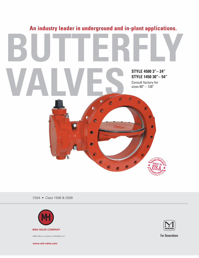
BUTTERFLY VALVES
An industry leader in underground and in-plant applications.
STYLE 4500 3”– 24” STYLE 1450 30”– 54” Consult factory for sizes 60” – 120”
C504 • Class 150B & 250B
M&H Valve is a division of McWane, Inc.
www.mh-valve.com
BUTTERFLY VALVESRECOMMENDED SPECIFICATIONS
1. All butterfly valves shall be of the rubber-seated, tight-closing type. They shall meet or exceed AWWA standard C504, latest edition, Class 150. All valves shall be M&H 4500/1450 butterfly valves, or approved equal.
2. Both ends shall be ANSI A21.11 mechanical joint or per flanged ANSI B16.1 (or as otherwise noted on plans and specs).
3. Valve shafts shall be ASTM A276 Type 304 stainless steel. Each valve shaft shall be of a one-piece design for valves 12” and smaller and a two-piece design for valves 14” and larger. Valve shafts shall have a minimum diameter extending through the valve bearings and into the valve disc as specified in AWWA C504. All valve shafts must meet or exceed the minimum connection torque requirement set forth in AWWA C504.
4. For valve sizes 3” – 16”, valve body and vane shall be high- strength cast iron to ASTM A126, Class B or high-strength ductile iron to ASTM A536 with ASTM A276 Type 304 stainless steel body seats.
5. For valves 18” and larger, valve body and vane shall be of high-strength ductile iron to ASTM A536, Grade 70-50-05 with ASTM A276 Type 304 stainless steel body seat.
6. Rubber valve seats shall be a full-circle 360 degree, seat not penetrated by the valve shaft. Valve seat shall be EPDM for cold or high water temperature applications.
7. The valve seat will be attached to the valve vane by 18-8 Type 304 stainless steel self-locking fasteners. The valve seat must be easily field adjustable and replaceable without any special tools or lengthy curing time.
8. Valve shaft seals shall be of the O-ring type and utilize the same elastomer as specified for the valve seats and for the intended service. Valves using self-compensating split V-type packing will not be accepted. All valve shaft seals must be easily field replaceable.
9. Valve actuator shall be of the traveling nut type, sealed and lubricated for underground or in-plant service. Operator shall be capable of withstanding an overload input torque of 450 ft-lbs. at full-open or full-closed position without damage to the valve operator. Operators for valves 14” and larger must have a 304 stainless steel external stop limiting device and travel adjustment. The travel adjustments must be able to be operated without removing the valve from the line or removing the actuator cover. No internal travel adjustment devices will be acceptable. All valve actuators must be sized per AWWA C504. Certification of proof of design and torque requirements shall be submitted to the owner upon request.
10. Handcrank, Handwheel or Chainwheel – All manual operators for service other than underground shall have a position indicator and shall be totally enclosed and permanently lubricated. Actuators shall be designed to produce the required operating torque with a maximum rim pull of 80 lb. on handwheel or chainwheel and a maximum input of 150 ft. lb. on operating nuts.
11. Cylinder – Cylinder operator shall be of the base mounted configuration. Cylinder barrel shall be of molybdenum-disulfide lined glass fiber reinforced epoxy tubing, to provide a corrosion-free, self-lubricated high-strength barrel. Rod seal shall be of urethane, molybdenum-disulfide filled, to provide a self-lubricated, long life seal.
12. The valve interior and exterior surfaces shall be coated in accordance with the latest revisions of AWWA C504 andmust be NSF 61 Certified.
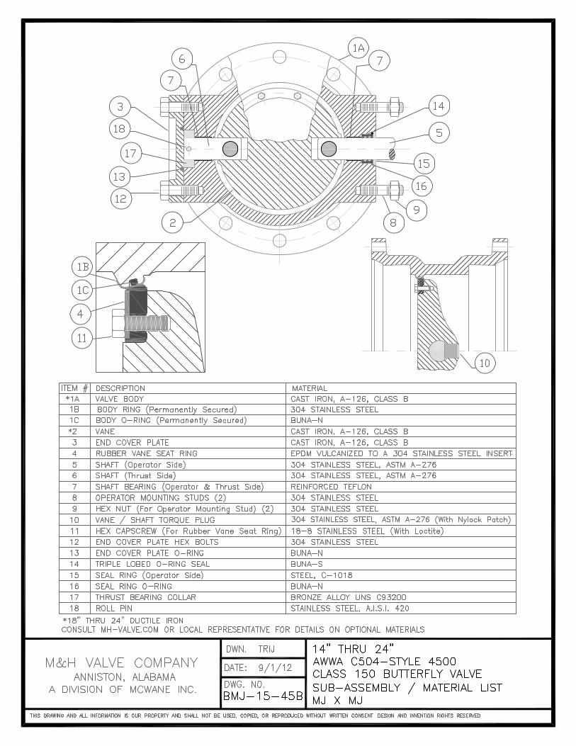
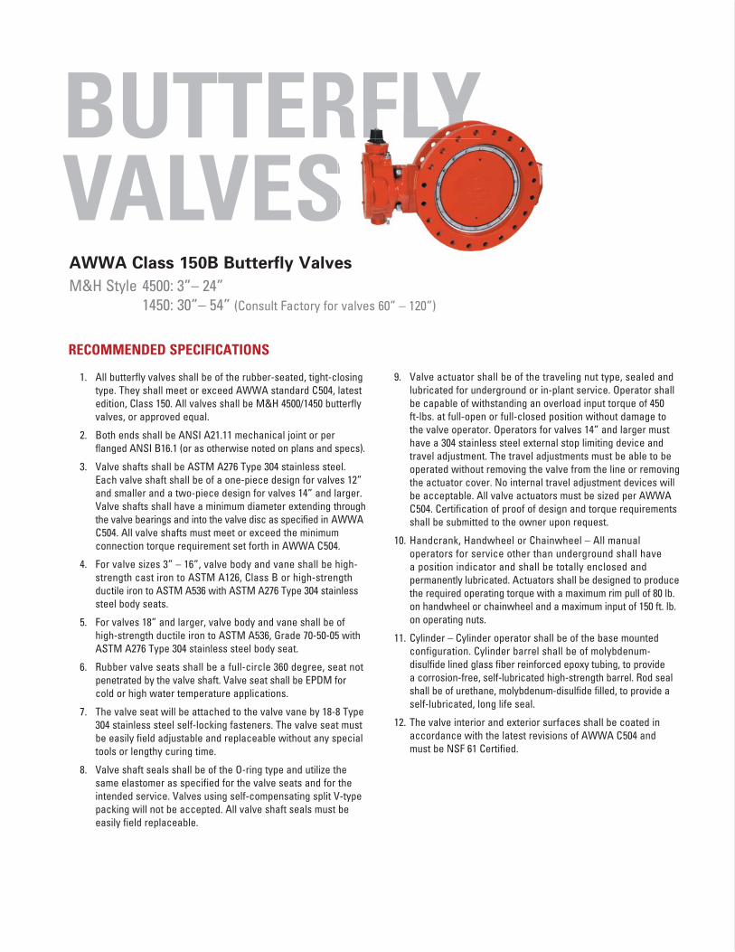
AWWA Class 150B Butterfly Valves
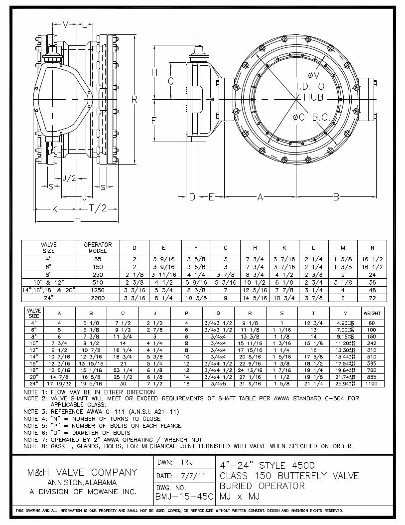
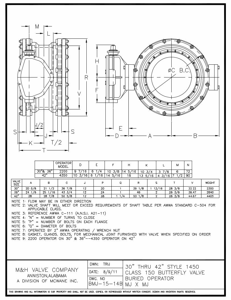
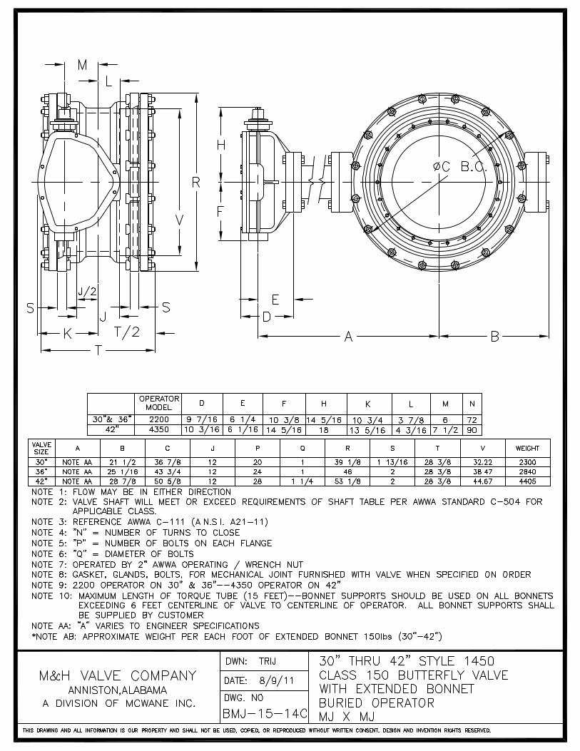
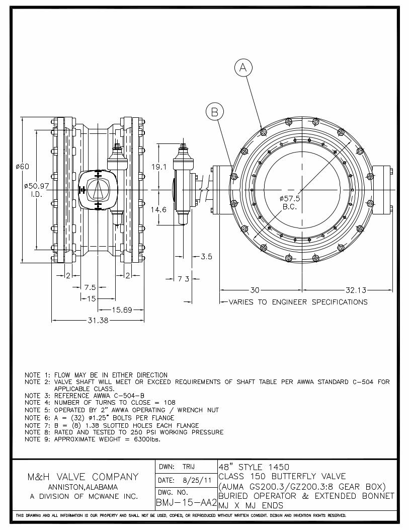
M&H Style 4500: 3”– 24” 1450: 30”– 54” (Consult Factory for valves 60” – 120”)

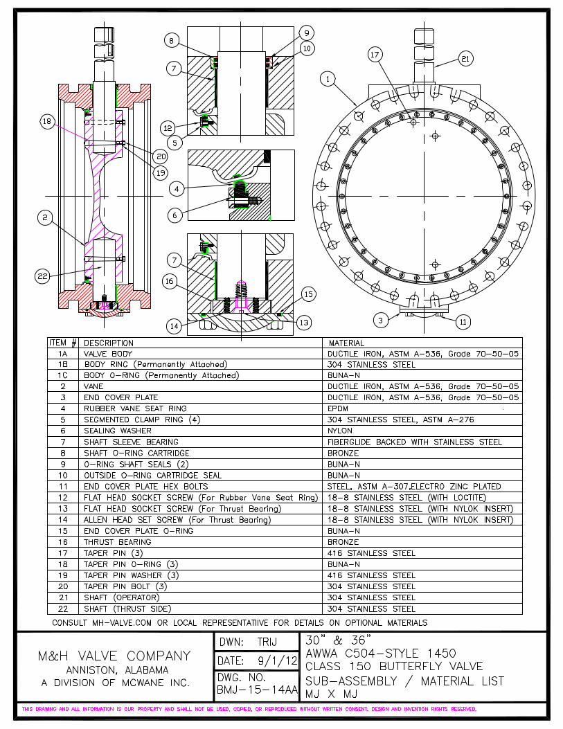
ENGINEERING FEATURESSTYLE 1450 BUTTERFLY VALVE30”– 54”The Class 150B 36” valve is featured in this cutaway. Check out mh-valve.com for additional materials, end configurations by size and pressure class options.
O-RING CARTRIDGEMaximum shaft sealing efficiency with a non-adjustable bronze O-ring cartridge
BEARINGSGenerously sized,
stainless steel backed, Teflon bearings provided
on operator and thrust ends are self-lubricated,
providing low friction support for the life of the
valve. No maintenance is required.
TAPER PINSFull metal-to-metal contact, vane to shaft connection is accomplished by stainless steel taper pins secured with stainless steel lock nuts.
SEALING SYSTEMSealing system in which the seal
is locked into a vane recess and is further restrained by a segmented
clamp ring. Seal relaxation when the valve is in the open position
is eliminated.
You are assured of uninterrupted 360 degree reliable and mechanically
adjusted sealing as well as reduced wear and lower seating torque. Should
field adjustment be required, one person with a torque wrench does the
job without valve disassembly.
STAINLESS STEEL SHAFTRuggedly constructed valveshafts of 304 stainless steelmeet or exceed AWWAstandard C504.
VALVE BODYHeavy duty ASTM
A536 ductile iron body designed and
manufactured to meet or exceed AWWA
standard C504.
OFFSET VANE DESIGN
Newly engineered vane provides large free flow area without sacrificing
vane strength. Vane construction is of A536
ductile iron to meet or exceed AWWA
standard C504.
ADJUSTABLE THRUST BEARINGBronze thrust bearing accurately centers vane in valve body. Accurate alignment is held in installation position. Factory adjusted for life of the valve.
1 VANE
2 360 DEGREE RUBBER SEAT
3 STAINLESS STEEL SELF-LOCKING SCREW FASTENER; WITH NYLON SLEEVE
4 STAINLESS STEEL BODY SEAT RING
5 STAINLESS STEEL SEAT RETAINING RING
6 VALVE BODY
AWWA C504 BUTTERFLY VALVES
450 FT-LBS. OVERLOAD PROTECTION. Overloads developed by excessive input torque are absorbed instead of being transmitted to mechanism and valve. Lets you apply up to 450 ft-lbs. input torque at open and closed positions without damage to valve or operator.
PERMANENTLY SEALED. Underground operator is permanently lubricated and sealed from ground water.
REDUCES WATER HAMMER. Operator design is such that constant input speed results in variable output speed with slowing down of valve closure at ends of travel. This effect reduces water hammer, while maintaining rated output torque throughout entire travel.
AWWA OPERATING NUT. The two-inch square operating nut on the underground operator is clearly marked with “open” and direction arrow. All other operators have position indicators, which clearly show “open-shut” positions.
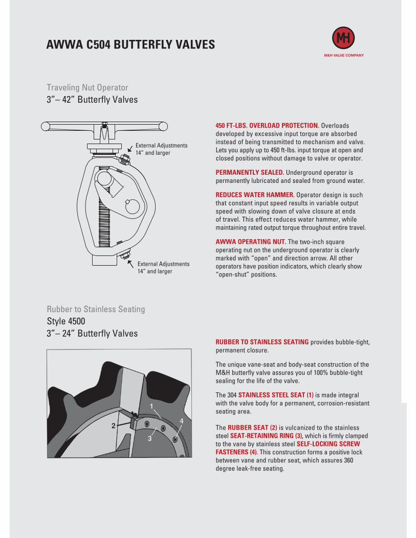
RUBBER TO STAINLESS SEATING provides bubble-tight, permanent closure.
The unique vane-seat and body-seat construction of the M&H butterfly valve assures you of 100% bubble-tight sealing for the life of the valve.
The 304 STAINLESS STEEL SEAT (1) is made integral with the valve body for a permanent, corrosion-resistant seating area.
The RUBBER SEAT (2) is vulcanized to the stainlesssteel SEAT-RETAINING RING (3), which is firmly clamped to the vane by stainless steel SELF-LOCKING SCREW FASTENERS (4). This construction forms a positive lock between vane and rubber seat, which assures 360 degree leak-free seating.
External Adjustments 14” and larger
External Adjustments 14” and larger
Traveling Nut Operator3”– 42” Butterfly Valves
Rubber to Stainless SeatingStyle 45003”– 24” Butterfly Valves

ACCESSORIES / OPTIONS
FLOOR STANDS
F5500 N.R.S.F5505 N.R.S. INDICATING
MOTOR OPERATOR
STEM GUIDES
F5660
T-HANDLE VALVE
WRENCHES
F2520 RIGID WRENCH
EXTENSION STEMS
UP TO 2 1/4” DIAMETERS ANY LENGTH
FLOOR BOX
F5695 BUSHED TO MEET STEM DIAMETER SPEC
MAX. LENGTH 12”MAX. STEM DIAMETER 2 1/4”
SIZE MIN. LENGTH* MAX. LENGTH*
#1 2 1/2” 17” #2 15” 24” #3 24” 35”
* Distance from wall
CYLINDER OPERATOR
605 West 23rd Street • Anniston, Alabama 36201
PHONE 256-237-3521 FAX 888-549-5309
M&H Valve is a division of McWane, Inc.
www.mh-valve.com
COMMITTED TO ENVIRONMENTAL RESPONSIBILITY
M&H VALVE COMPANY IS COMMITTED TO PROTECTING OUR NATURAL RESOURCES
THROUGH ENVIRONMENTALLY RESPONSIBLE MANUFACTURING PRACTICES, INCLUDING THE USE OF 80+% RECYCLED CONTENT IN OUR HYDRANTS AND VALVES.
To learn more about our commitment to the environment, call 800-829-2569.