Embed Size (px)
Citation preview

SW
ITC
HG
EA
R
ENERGY SAFELY SWITCHED
BUSBAR SYSTEM 60 mm

SWITCHGEAR
ENERGYsafely switched
Who we are?GrupaApatorisadynamicPolishcapitalgroup,itcurrentlyincludes14companies–8Polishand6foreign.GrupaApatorisapioneerintheimplementationofinnovativetechnicalsolutionsanditssalesincomegrowseveryyear.ThankstotheapplicationofmoderntechnologiesourproductshavethehighestqualityandwintherecognitionofourClients.
OfferGrupaApatorfocusesitsactivityintwosegmentsoftheelectromechanicalindustry:meteringandswitchgear.OfferofthecompaniesofGrupaincludesmeteringequipmentforallutilities(prepaymentandpost-paymentelectricalenergymeters,heatmeters,gasmeters,watermeters,temperaturesensors).Theaboveofferisabaseforthedevelopmentofsystemsenablingenergyusagemetering,remotereading,teletransmissionandvisualisationofdata.GrupaApatorhasastrongpositionandyearsofexperienceconcerningsafemakingandbreakingofelectricalcircuits.
About Grupa Apator

CO
NTE
NTS
Apator
� ESTABLISHED SINCE:1949.
� BUSINESS ACTIVITY:Thebusinessactivitycovers:design,
production,salesofmetering
equipmentandsystemsand
switchgearequipment.Standard
productofcompanyareasfollows:
LEWsystemAPATOR,AMRsystem
APATOR,prepaymetelectricity
meters,surgearresters,ARS,PBS,
RBKtypeapparatusesand4Gseries
rotarycamswitchers.
� CERTIFICATES:TheIntegratedManagementSystem
includingtheQualityManagement
System,EnvironmentalManagement
SystemandOccupationalHealth
andSafetyManagementSystemhas
beenassessedandfoundtobein
accordancewiththerequirementsof:
ISO9001:2008,
ISO14001:2004,
PN-N-18001:2004.
� DID YOU KNOW THAT:Lightningstrikessomewhereonthe
Earthsixthousandtimesperminute,
mostlyintropicalareas.Theaverage
lightningboltis1kmlong,butsome
canreachmorethan10km.
Thelongestrecordedlightningbolt
was150km!
ENERGY SAFELY SWITCHED
3
1. Busbar System 60mm “System 60” 04
1.1 Universal busbar support _________________ 06
1.2 Busbar support for 100 mm and 185 mm system ___ 08
1.3 Input clamps ______________________________ 09
1.4 Bus mounting fuse base E18 ___________________11
1.5 Component adaptor ________________________12
1.6 RBD0/60 D0-bus mounting switch disconnector fuse _______ 15
1.7 Partitions and shrouds _____________________19
2. D02-Fuse links 20
3. Fuse switch disconnectors 22

4
SWITCHGEAR
BUSBAR SYSTEM 60 mmBUSBAR SYSTEM 60 mm “ SYSTEM 60” is a modular designedcurrent distribution system up to 630 A.Snap on mounting of all components provides extreme flexibility in assembly and add on design.
SWITCHGEAR

ENERGY SAFELY SWITCHED
5
ENERGY SAFELY SWITCHED
6
SWITCHGEAR
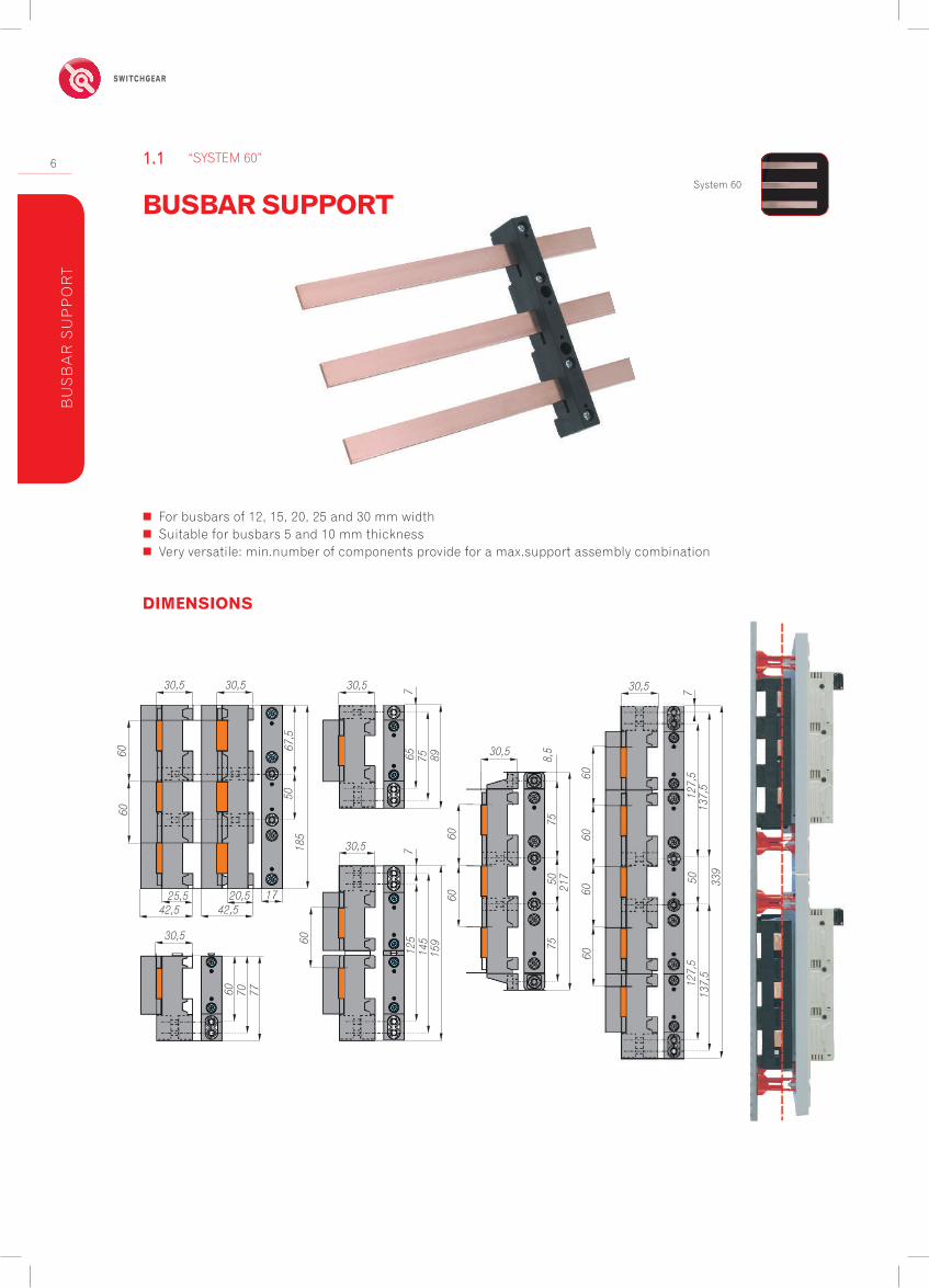
� For busbars of 12, 15, 20, 25 and 30 mm width � Suitable for busbars 5 and 10 mm thickness � Very versatile: min.number of components provide for a max.support assembly combination
System 60
BUSBAR SUPPORT
“SYSTEM 60”1.1
BU
SB
AR
SU
PP
OR
T
DIMENSIONS
185
67,5
50
1720,542,5
25,542,5
30,5
60 70 77
60
30,5 712
514
515
960
60
8,5
7550
30,5
75
6060
127,
513
7,5
50 339
60
217
30,512
7,5
137,
577
65 75 89
30,530,5 30,5
6060
60

ENERGY SAFELY SWITCHED
7
Table 1. VERSIONS
Item ItemNo. kg/pc Packaging
Busbar support 3-pole, 2 –hole mounting inside; incl. spacer and fixing screws 0000106300T 0,121 20
External fixing with item 10 6300 incl. fixing screws for 4-hole assembly 0000106301T 0,006 10
Busbar support 1-pole, fixed to 10 6300 or for 2-pole; incl. spacer and fixing screws 0000106302T 0,048 10
Busbar support 1-pole, for single assembly; incl. spacer and fixing screws 0000106304T 0,056 10
Combi joiner; for the assembly of a 2-pole busbar with 2 X 0000106302T 0000106307T 0,004 10
End cap 3-pole; yellow with warning triangle 0000106303T 0,019 10
Z-end cap 3-pole; yellow with warning triangle 0000106308T 0,024 10
End cap 1-pole 0000106310T 0,006 10
Z-end cap 1-pole 0000106311T 0,007 20
Fixing screw 25 mm 0000106309T 0,004 20
Fixing screw 10 mm 0000106312T 0,002 10
Busbar support 2-pole; 1-hole mounting assembly 0000106004T 0,08 10
Busbar support 2-pole; 2-hole mounting assembly 0000106005T 0,09 10
0000106300Tendcap3-pole
0000106308TZ-endcap3-polealso as side protection for the bus mounting fuse base
0000106309Tfixing-screw25mm
0000106300Tbusbarsupport3-pole 2-hole assemby inside 0000106312Tfixingscrew10mm0000106301Texternalfitting for 4- hole assembly
0000106310Tendcap1-pole
0000106311TZ-endcap1-pole
0000106309Tfixingscrew25mm0000106302Tbusbarsupport3-polefixablefor extending a 4- or 5-pole bus bar0000106307Tcombijoiner for the assembly of a 2-pole bus base
0000106310Tendcap1-pole0000106311TZ-endcap1-pole
0000106309Tfixingscrew25mm
2x0000106302Tbusbarsupport2-pole2-hole assembly
ACCESSORIES FOR “SYSTEM 60”
BU
SB
AR
SU
PP
OR
T
Busbar support spacing
Rat
ed p
eak
with
stan
d cu
rren
t Ipk
[kA
]
Short-circuit rating diagram according to DIN EN 60439 System 60 mm
Rated operational voltage: 690 V, Rated frequency: 50 Hz
6012
,5
6004
58,5
116
1833
4550
6012
,5
6005
58,5
132
1833
4550
66
30 x 10 mm
30 x 5 mm
20 x 10 mm20 x 5 mm

8
SWITCHGEARB
US
BA
R S
UP
PO
RT
Table 2. TECHNICAL DATA
Table 3. VERSIONS
Item
Rated operational voltage 1000 V ACRated insulation voltage 2000 V ACRated frequency 50 HzFire classification UL 94 V40Creep resistance CTI 600Temperature withstand 150°Glow wire 960°
Item Item-No. kg/pc. Packaging
3-pole busbar support system 100 mm 0000188100T 0,36 13-pole busbar support system 185 mm 0000188101T 0,54 11-pole busbar support 0000188102T 0,20 1end cup 3-pole system 100 mm 0000188103T 0,07 1end cup 3-pole system 185 mm 0000188104T 0,12 1
BUSBAR SUPPORT FOR 100 mm and 185 mm system
BUSBAR SUPPORT SYSTEM1.2
DIMENSIONS
� Without drilling mounting of busbar � Busbar width 30 – 120 mm (System 185 mm)
� Busbar width 30 – 60 mm (System 100 mm)
� Busbar thickness: 10 mm
M6 DIN 912 busbar fixing
2 mounting holes DIN 912 M8 tightening torque 20 Nm +/-2 Nm
DIN 912 M8 tightening torque 20 Nm +/-2 NmM6 DIN 912 (busbar fixing)
224
200
12
50
2530,5
324
300
12
502530,5
100
100
10
573 17
5
1250
2530,518
518
5
200
M6 DIN 912 busbar fixing
175
ENERGY SAFELY SWITCHED
9
DIMENSIONS
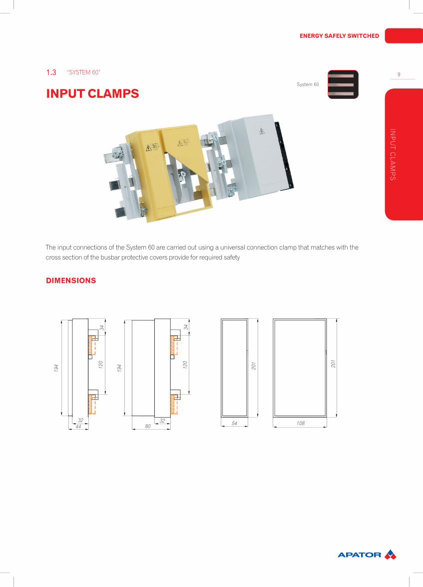
The input connections of the System 60 are carried out using a universal connection clamp that matches with the cross section of the busbar protective covers provide for required safety
System 60
INPUT CLAMPS
“SYSTEM 60”1.3
INP
UT C
LAM
PS
201
201
120
108544432
34
194 12
0
8032
34
194
DIN 912 M8 tightening torque 20 Nm +/-2 NmM6 DIN 912 (busbar fixing)

10
SWITCHGEARIN
PU
T C
LAM
PS
Item(yellow) Item-No. kg/pc. Packaging
54 mm wide, internal height 42 mm, for clamps 16…50 mm2 0000106090T 0,11 2
108 mm wide, internal height 42 mm, for clamps 16…70 mm2 0000106091T 0,17 1
108 mm wide, internal height 78 mm, for clamps 16…185 mm2 0000106092T 0,22 1
Item(grey) Item-No. kg/pc. Packaging
54 mm wide, internal height 42 mm, for clamps 16…50 mm2 0000106096T 0,11 2
108 mm wide, internal height 42 mm, for clamps 16…70 mm2 0000106097T 0,17 1
108 mm wide, internal height 78 mm, for clamps 16…185 mm2 0000106098T 0,22 1
Item Item-No. kg/pc. Packaging
54 mm wide, internal height 42 mm2 0000106033T 0,09 2
108 mm wide, internal height 42 mm2 0000106034T 0,12 1
108 mm wide, internal height 78 mm2 0000106035T 0,12 1
Table 4. Connection clamps and protection covers with yellow warning triangle including conductor and busbar protection cover
Table 5. Busbar protection cover, grey
Table 6. Pressure clamps
ACCESSORIES FOR SYSTEM 60 mm
for5mmbusbarsthickness Item-No. kg/pc. Packaging
1,5…16 mm2 0000116051T 0,03 100
1,5…35 mm2 0000116052T 0,04 50
1,5…50 mm2 0000116053T 0,05 50
16…70 mm2 0000116054T 0,06 10
16…120 mm2 0000116055T 0,09 10
16…185 mm2 0000116056T 0,10 10
for10mmbusbarsthickness
1,5…16 mm2 0000116061T 0,03 100
1,5…35 mm2 0000116062T 0,04 50
1,5…50 mm2 0000116063T 0,05 50
16…70 mm2 0000116064T 0,06 10
16…120 mm2 0000116065T 0,09 10
16…185 mm2 0000116066T 0,10 10

ENERGY SAFELY SWITCHED
11
BU
S M
OU
NTIN
G FU
SE
BA
SE
E18
DIMENSIONS
Table 7. TECHNICAL DATA
Item Item-No. kg/pc. Packaging
Bus mounting fuse base 27 mm, without cover 0000106022T 0,15 10Bus mounting fuse base 27 mm, with cover 0000106023T 0,17 10Bus mounting fuse base 36 mm, with cover and lateral extension 0000106028T 0,19 10Bus mounting fuse base 54 mm, with cover and lateral extension 0000106029T 0,21 10Cover shroud 27 mm 0000106011T 0,02 10Cover shroud 36 mm, incl. extension 0000106012T 0,03 10Cover shroud 54 mm, incl. extension 0000106013T 0,05 10Shroud pair 0000106016T 0,05 10Single left 0000106017T 0,02 10Single right 0000106018T 0,02 10Clip on touch protection shroud with back of hand protection 0000106026T 0,01 10
� Distinctive labeling on the base � Low loss stainless steel terminal clamps � Contact protection shroud on the sides � Clip on rear touch protection shroud
3-pole;DIN49524For D0-fuse links 2…63A DIN 49522Cartridge ring adaptor D02 DIN 49523 400 V AC/250 DC 50 kAeff
Cage clamps steel 1,5…25 mm2, 3-4 NmCreep resistance CTI 600Fire classification UL 94-V0Temperature withstand 200 °CGlow wire 960 °C
Table 8. VERSIONS
BUS MOUNTING FUSE BASE E18
“SYSTEM 60”1.4System 60
0000106022T 0000106011T 0000106012T 0000106013T 0000106017T 0000106018T0000106016T (pair)
0000106016T (Pair) for masking the middle of bus bar supports or for use on left or right frames at the beginning or end of a bus base
Frame coveringfor the switchboard
201
6060
34,5
ca.5032 40
27 27 36 54 36 36

12
SWITCHGEARC
OM
PO
NE
NT
AD
AP
TOR
DIMENSIONS
Table 9. TECHNICAL DATA
Item Item-No. kg/pc. Packaging
Ie=25AconnectioncablecrosssectionAWG12/4mm2
1 universal mounting rail, 45 mm wide 0106142451T 0,21 22 universal mounting rail, 45 mm wide 0106142452T 0,23 21 universal mounting rail, 54 mm wide 0106142541T 0,22 22 universal mounting rail, 54 mm wide 0106142542T 0,24 2
Ie=35AconnectioncablecrosssectionAWG10/6mm2
1 universal mounting rail, 45 mm wide 0106143451T 0,22 22 universal mounting rail, 45 mm wide 0106143452T 0,24 21 universal mounting rail, 54 mm wide 0106143541T 0,23 22 universal mounting rail, 54 mm wide 0106143542T 0,25 21 universal mounting rail, 63 mm wide 0106143631T 0,27 21 universal mounting rail, 72 mm wide 0106143721T 0,29 22 universal mounting rail, 81 mm wide 0106143812T 0,31 2
Ie=63AconnectioncablecrosssectionAWG8/10mm2
1 universal mounting rail, 54 mm wide 0106146541T 0,26 22 universal mounting rail, 54 mm wide 0106146542T 0,28 21 universal mounting rail, 63 mm wide 0106146631T 0,30 21 universal mounting rail, 72 mm wide 0106146721T 0,32 22 universal mounting rail, 81 mm wide 0106146812T 0,34 2
Ie=63AconnectioncablecrosssectionAWG6/16mm2
1 universal mounting rail, 54 mm wide 0106148541T 0,29 22 universal mounting rail, 54 mm wide 0106148542T 0,31 21 universal mounting rail, 63 mm wide 0106148631T 0,33 21 universal mounting rail, 72 mm wide 0106148721T 0,35 22 universal mounting rail, 81 mm wide 0106148812T 0,37 2
Component adaptor with steplessly adjustable mounting support and low loss dual contact
COMPONENT ADAPTOR
“SYSTEM 60”1.5
106142106143106146106148
106152106153
106140106142106143106146106148106152106153 106110
32
24,5
6060
14
20,5 45 24 9
182
182
32
24,5
6060
14
20,5

ENERGY SAFELY SWITCHED
13
Table 10. VERSIONS
Item Item-No. kg/pc. Packaging
Ie = 25 A; 4 mm2 connection cable cross section, AWG 12 wide 45 mm 0000106142T 0,19 4
Ie = 35 A; 6 mm2 connection cable cross section, AWG 10 wide 45 mm 0000106143T 0,20 4
Ie = 63 A; 10 mm2 connection cable cross section, AWG 8 wide 45 mm 0000106146T 0,23 4
Ie = 80 A; 16 mm2 connection cable cross section, AWG 6 wide 45 mm 0000106148T 0,26 4
Ie = 25A; Double central terminal 4 mm2, AWG 12, 45 mm wide 0000106152T 0,20 4
Ie = 35A; Double central terminal 6 mm2, AWG 10, 45 mm wide 0000106153T 0,25 4
Without contacts; incl. X connector for lateral extension or single mounting 0000106140T 0,15 4
Item Item-No. kg/pc. Packaging
Lateral extension piece for the adaptor in 9 mm steps 0000106110T 0,02 10
Universal mounting rail 45 mm wide; steplessly adjustable 0000106104T 0,02 10
Universal mounting rail 54 mm wide; steplessly adjustable 0000106105T 0,02 10
Universal mounting rail 63 mm wide; steplessly adjustable 0000106106T 0,02 10
Universal mounting rail 72 mm wide; steplessly adjustable 0000106107T 0,02 10
Universal mounting rail 81 mm wide; steplessly adjustable 0000106108T 0,02 10
ACCESSORIES
Mounting rails are steplessly adjustable with dual wedge fastening
Adapter Base 9 mm side part enables an individuell extensionof the base in steps of 9 mm
Mounting rail with dual wedge fastening
Position the upper mounting rail and fasten from the front.
1. Place the component on the top mounting rail and connect
2. Place the component on the lower mounting rail. Position the lower mounting rail to suit component and then connect.
Fasten lower mounting rail from below
COMPONENT ADAPTOR
“SYSTEM 60”1.5
Table 11. VERSIONS
CO
MP
ON
EN
T AD
AP
TOR
COMPONENT ADAPTOR
14
SWITCHGEARC
OM
PO
NE
NT
AD
AP
TOR
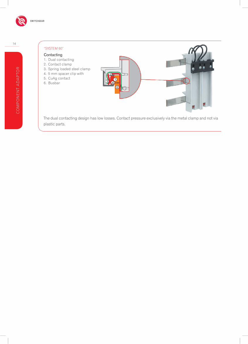
Contacting1. Dual contacting2. Contact clamp3. Spring loaded steel clamp4. 5 mm spacer clip with5. CuAg contact6. Busbar
The dual contacting design has low losses. Contact pressure exclusively via the metal clamp and not via plastic parts.
“SYSTEM 60”
ENERGY SAFELY SWITCHED
15
RB
D0/60
DO
-BU
S MO
UN
TING
SWITC
H D
ISCO
NN
ECTO
R FU
SE
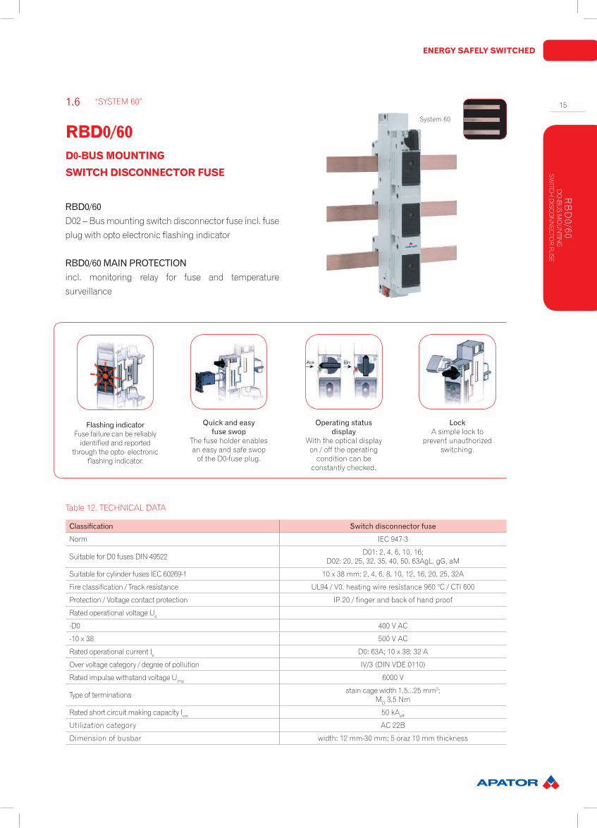
FlashingindicatorFuse failure can be reliably
identified and reported through the opto- electronic
flashing indicator.
Quickandeasyfuseswop
The fuse holder enablesan easy and safe swop
of the D0-fuse plug.
Operatingstatusdisplay
With the optical displayon / off the operating
condition can beconstantly checked.
LockA simple lock to
prevent unauthorizedswitching.
RBD0/60D02 – Bus mounting switch disconnector fuse incl. fuse plug with opto electronic flashing indicator
RBD0/60MAINPROTECTIONincl. monitoring relay for fuse and temperature surveillance
Classification Switchdisconnectorfuse
Norm IEC 947-3
Suitable for D0 fuses DIN 49522 D01: 2, 4, 6, 10, 16;D02: 20, 25, 32, 35, 40, 50, 63AgL, gG, aM
Suitable for cylinder fuses IEC 60269-1 10 x 38 mm: 2, 4, 6, 8, 10, 12, 16, 20, 25, 32A
Fire classification / Track resistance UL94 / V0, heating wire resistance 960 °C / CTI 600
Protection / Voltage contact protection IP 20 / finger and back of hand proof
Rated operational voltage Ue
-D0 400 V AC
-10 x 38 500 V AC
Rated operational current Ie D0: 63A; 10 x 38: 32 A
Over voltage category / degree of pollution IV/3 (DIN VDE 0110)
Rated impulse withstand voltage Uimp 6000 V
Type of terminations stain cage width 1,5...25 mm2;MD 3,5 Nm
Rated short circuit making capacity Icm 50 kAeff
Utilization category AC 22B
Dimension of busbar width: 12 mm-30 mm; 5 oraz 10 mm thickness
Table 12. TECHNICAL DATA
RBD0/60 D0-BUS MOUNTINGSWITCH DISCONNECTOR FUSE
“SYSTEM 60”1.6System 60
16
SWITCHGEAR
DIMENSIONS
RB
D0/
60D
O-B
US
MO
UN
TIN
GSW
ITC
H D
ISC
ON
NEC
TOR
FU
SE
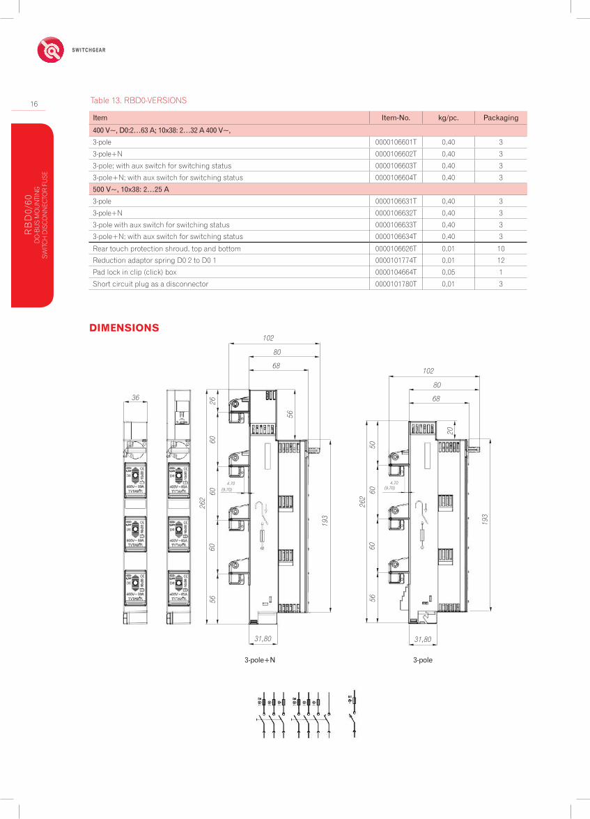
Table 13. RBD0-VERSIONS
Item Item-No. kg/pc. Packaging
400V~,D0:2…63A;10x38:2…32A400V~,3-pole 0000106601T 0,40 3
3-pole+N 0000106602T 0,40 3
3-pole; with aux switch for switching status 0000106603T 0,40 3
3-pole+N; with aux switch for switching status 0000106604T 0,40 3
500V~,10x38:2…25A3-pole 0000106631T 0,40 3
3-pole+N 0000106632T 0,40 3
3-pole with aux switch for switching status 0000106633T 0,40 3
3-pole+N; with aux switch for switching status 0000106634T 0,40 3
Rear touch protection shroud, top and bottom 0000106626T 0,01 10
Reduction adaptor spring D0 2 to D0 1 0000101774T 0,01 12
Pad lock in clip (click) box 0000104664T 0,05 1
Short circuit plug as a disconnector 0000101780T 0,01 3
3-pole+N 3-pole
102
80
68
31,80
5660
6026
2
(9.70)
6026
4.70
56
193
36
102
80
68
31,80
5660
6026
2
(9.70)
50
4.70
20
193
ENERGY SAFELY SWITCHED
17
RB
D0/60
MA
IN P
RO
TEC
TION
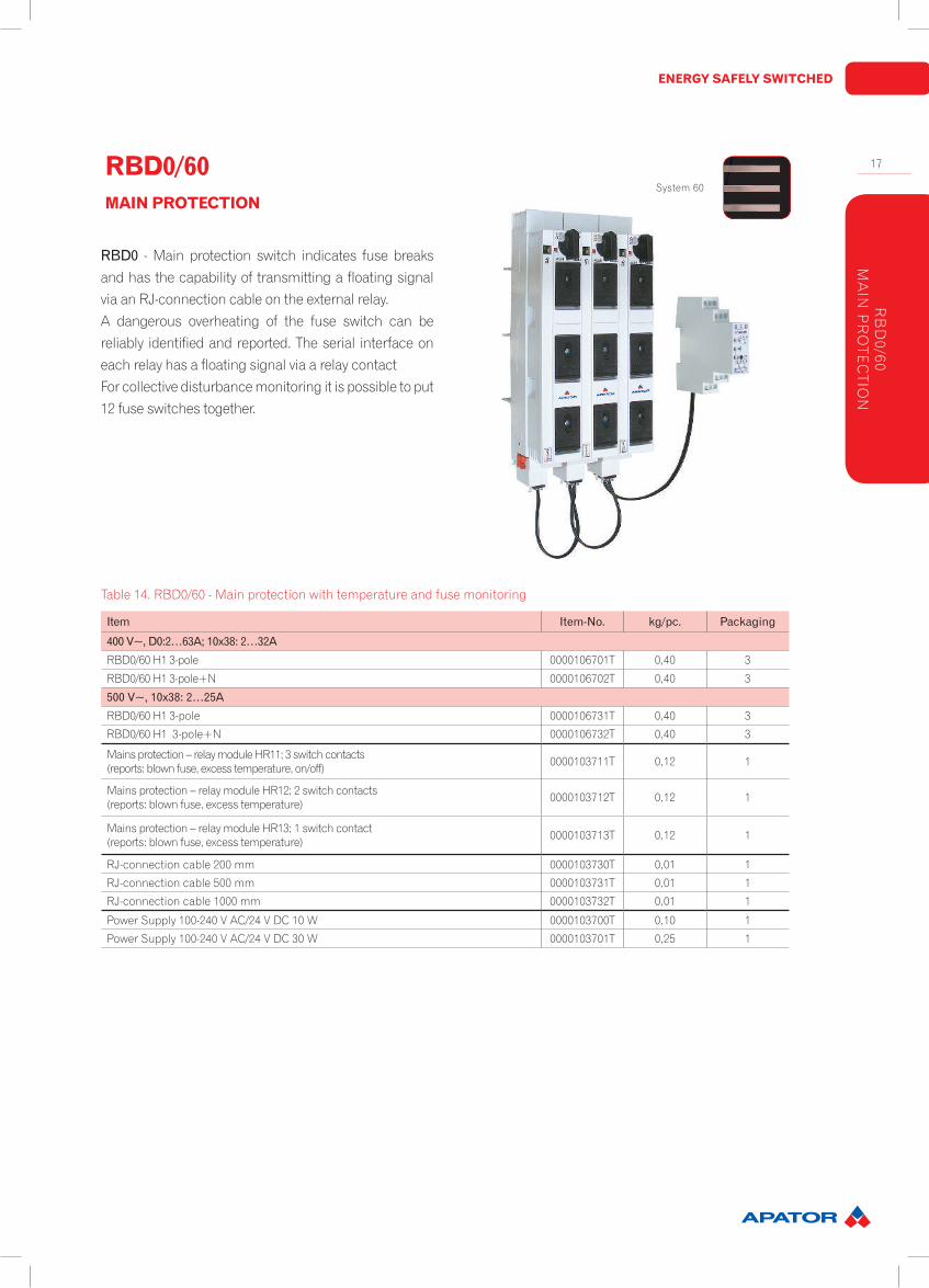
RBD0 - Main protection switch indicates fuse breaks and has the capability of transmitting a floating signal via an RJ-connection cable on the external relay. A dangerous overheating of the fuse switch can be reliably identified and reported. The serial interface on each relay has a floating signal via a relay contact For collective disturbance monitoring it is possible to put 12 fuse switches together.
Table 14. RBD0/60 - Main protection with temperature and fuse monitoring
Item Item-No. kg/pc. Packaging
400V~,D0:2…63A;10x38:2…32ARBD0/60 H1 3-pole 0000106701T 0,40 3
RBD0/60 H1 3-pole+N 0000106702T 0,40 3
500V~,10x38:2…25ARBD0/60 H1 3-pole 0000106731T 0,40 3
RBD0/60 H1 3-pole+N 0000106732T 0,40 3
Mains protection – relay module HR11; 3 switch contacts (reports: blown fuse, excess temperature, on/off) 0000103711T 0,12 1
Mains protection – relay module HR12; 2 switch contacts (reports: blown fuse, excess temperature) 0000103712T 0,12 1
Mains protection – relay module HR13; 1 switch contact (reports: blown fuse, excess temperature) 0000103713T 0,12 1
RJ-connection cable 200 mm 0000103730T 0,01 1
RJ-connection cable 500 mm 0000103731T 0,01 1
RJ-connection cable 1000 mm 0000103732T 0,01 1
Power Supply 100-240 V AC/24 V DC 10 W 0000103700T 0,10 1
Power Supply 100-240 V AC/24 V DC 30 W 0000103701T 0,25 1
RBD0/60 MAIN PROTECTION
System 60
18
SWITCHGEAR
RB
D0/
60
MA
IN P
RO
TEC
TIO
N
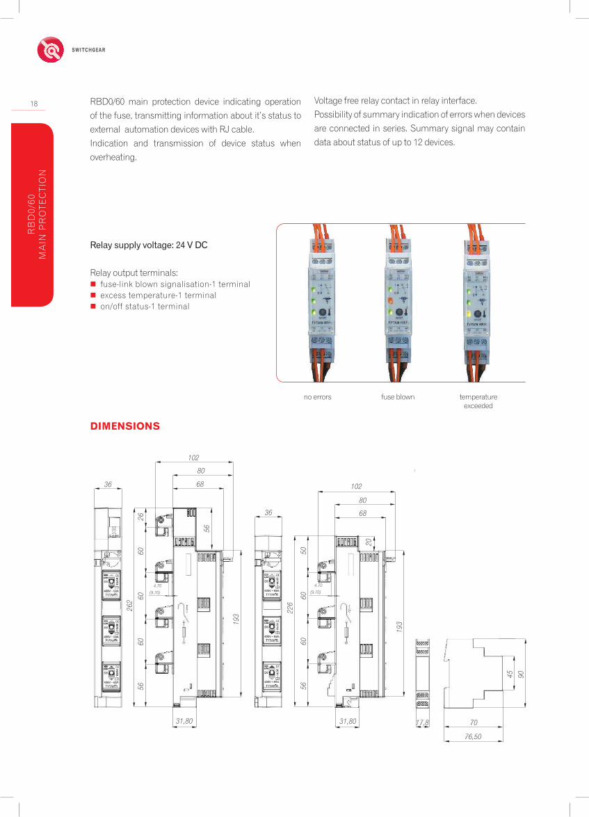
RBD0/60 main protection device indicating operation of the fuse, transmitting information about it’s status to external automation devices with RJ cable.Indication and transmission of device status when overheating.
Voltage free relay contact in relay interface. Possibility of summary indication of errors when devices are connected in series. Summary signal may contain data about status of up to 12 devices.
no errors fuse blown temperature exceeded
Relaysupplyvoltage:24VDC
Relay output terminals: � fuse-link blown signalisation-1 terminal � excess temperature-1 terminal � on/off status-1 terminal
DIMENSIONS
102
80
68
31,80
5660
6026
2
(9.70)
6026
4.70
56
193
102
80
68
31,80
5660
60
226
(9.70)
50
4.70
20
193
17,8
76,50
90
36
70
4536

ENERGY SAFELY SWITCHED
19
PA
RTITIO
NS
AN
D S
HR
OU
DS
The partition and shroud system offers comprehensive contact protection for the System 60
Table 15. Covering systems
Table 16. Busbar covering
Item Item-No. kg/pc. Packaging
Cover shroud for bus bar support 0000106300T 0000126070T 0,06 10
Side cover for partition and shroud system 0000126071T 0,03 10
Slitted shroud ; 2000 mm long 0000126072T 0,47 5
Closed shroud; 2000 mm long 0000126073T 0,53 5
Panel mount; support edge 32 mm 0000126074T 0,04 10
Panel cover 1000 mm long 0000126075T 0,64 2
Item Item-No. kg/pc. Packaging
Cover strips for 5 mm busbar 0000156076T 0,07 10
Cover strips for 10 mm busbar 0000156077T 0,09 10
PARTITIONS AND SHROUDS
“SYSTEM 60”1.7System 60
20
SWITCHGEARD
0-FU
SE
LIN
KS
Item Item-No. kg/pc. Packaging
12X 2A D01 in a box 1,5TE 0000101202T 0,10 1/24
12X 4A D01 in a box 1,5TE 0000101204T 0,10 1/24
12X 6A D01 in a box 1,5TE 0000101206T 0,10 1/24
12X 10A D01 in a box 1,5TE 0000101210T 0,11 1/24
12X 13A D01 in a box 1,5TE 0000101213T 0,11 1/24
12X 16A D01 in a box 1,5TE 0000101216T 0,11 1/24
12X 20A D02 in a box 3TE 0000101220T 0,18 1/12
12X 25A D02 in a box 3TE 0000101225T 0,18 1/12
12X 32A D02 in a box 3TE 0000101232T 0,19 1/12
12X 35A D02 in a box 3TE 0000101235T 0,21 1/12
12X 40A D02 in a box 3TE 0000101240T 0,21 1/12
12X 50A D02 in a box 3TE 0000101250T 0,22 1/12
12X 63A D02 in a box 3TE 0000101263T 0,22 1/12
Complete range 13X12 fuse link sets 2-63A 0000101200T 2,10 1
Item Item-No. kg/pc. Packaging
D01 2A 0000100202T 0,10 50
D01 4A 0000100204T 0,10 50
D01 6A 0000100206T 0,10 50
D01 10A 0000100210T 0,11 50
D01 13A 0000100213T 0,11 50
D01 16A 0000100216T 0,11 50
D02 20A 0000100220T 0,18 50
D02 25A 0000100225T 0,18 50
D02 32A 0000100232T 0,19 50
D02 35A 0000100235T 0,21 50
D02 40A 0000100240T 0,21 50
D02 50A 0000100250T 0,22 50
D02 63A 0000100263T 0,22 50
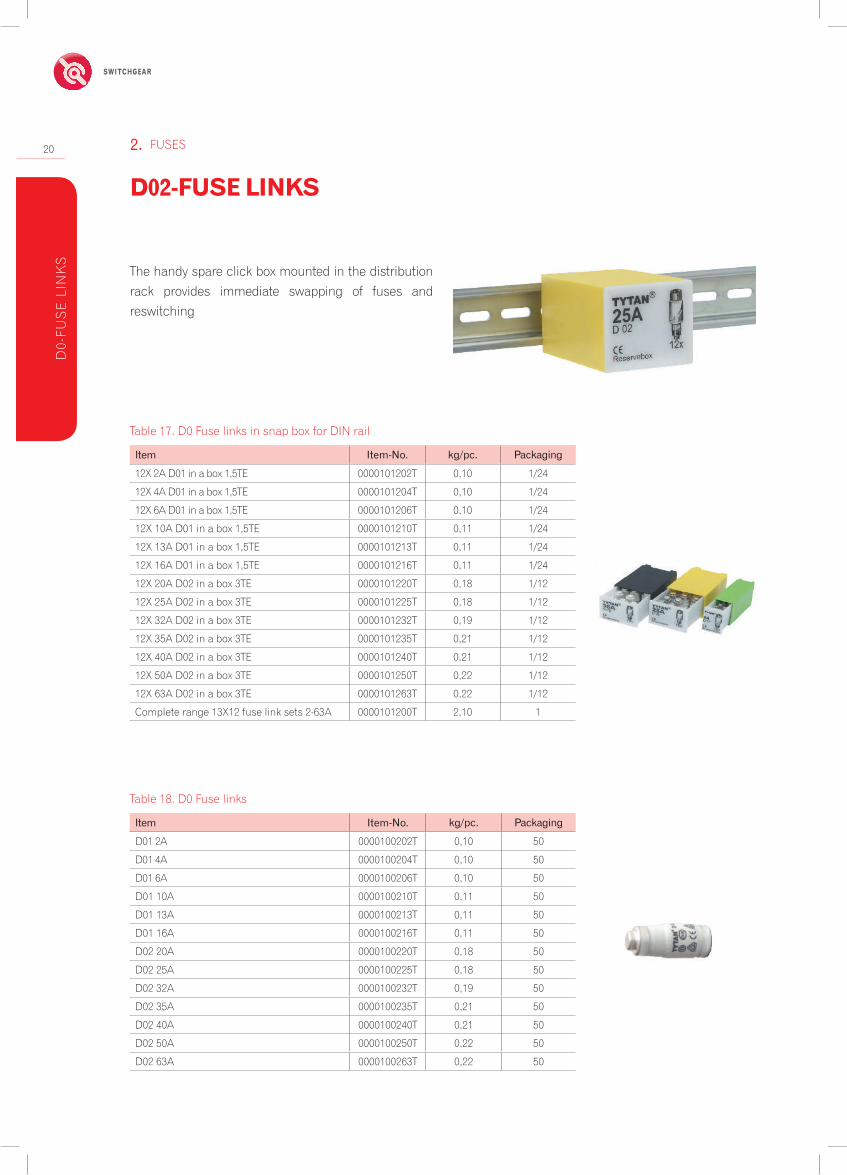
The handy spare click box mounted in the distribution rack provides immediate swapping of fuses and reswitching
Table 17. D0 Fuse links in snap box for DIN rail
Table 18. D0 Fuse links
D02-FUSE LINKS
FUSES2.

ENERGY SAFELY SWITCHED
21
Item Item-No. kg/pc. Packaging
12X 2A D01 in a box 1,5TE 0000101302T 0,03 1/2412X 4A D01 in a box 1,5TE 0000101304T 0,03 1/2412X 6A D01 in a box 1,5TE 0000101306T 0,03 1/2412X 10A D01 in a box 1,5TE 0000101310T 0,03 1/2412X 2A D02 in a box 3TE 0000101402T 0,03 1/2412X 4A D02 in a box 3TE 0000101404T 0,03 1/2412X 6A D02 in a box 3TE 0000101406T 0,03 1/2412X 10A D02 in Box 3TE 0000101410T 0,03 1/2412X 16A D02 in a box 3TE 0000101416T 0,03 1/2412X 20A D02 in a box 3TE 0000101420T 0,03 1/2412X 25A D02 in a box 3TE 0000101425T 0,03 1/2412X 35A D02 in a box 3TE 0000101435T 0,03 1/2412X 50A D02 in a box 3TE 0000101450T 0,03 1/24Complete range 13X12 cartridge ring adaptors 2-50A 0000101300T 0,39 1
Item Item-No. kg/pc. Packaging
D01 E14 2A 0000100302T 0,001 50D01 E14 4A 0000100304T 0,001 50D01 E14 6A 0000100306T 0,001 50D01 E14 10A 0000100310T 0,001 50D02 E18 2A 0000100402T 0,001 50D02 E18 4A 0000100404T 0,001 50D01 E18 6A 0000100406T 0,001 50D01 E18 10A 0000100410T 0,001 50D01 E18 16A 0000100416T 0,001 50D01 E18 20A 0000100420T 0,001 50D01 E18 25A 0000100425T 0,001 50D01 E18 35A 0000100435T 0,001 50D01 E18 50A 0000100450T 0,001 50
Item Item-No. kg/pc. Packaging
Cartridge ring adaptor wrench 0000101400T 0,02 1/12Screw cap D02 plastic with testing hole 0000126024T 0,01 20Adapter ring for D01 fuse links 0000121401T 0,01 20Screw cap D02 porcelain with testing hole 0000127024T 0,01 20Screw cap D01 porcelain with testing hole 0000127025T 0,01 20
Table 19. Cartridge ring adaptor in snap box for DIN rail
Table 20. Cartridge ring adaptor
Table 21. Accessories
D0-CARTRIDGERING ADAPTOR INSERTDIN 49523 DIN VDE 0636 IEC 60269 D
0-CA
RTR
IDG
E R
ING
AD
AP
TOR
INS
ER
T
22
SWITCHGEAR
RBP000pro Cableterminal ArticleNo.FormountingonplateRBP 000 pro for connection of round conductors frame clamps 63-823267-001
formountingondoubleDINrailRBP 000 pro-E-125 mm double DIN rail with spacing of 125 mm frame clamps 63-823267-002
RBP 000 pro-E-150 mm double DIN rail with spacing of 150 mm frame clamps 63-823267-003
RBK000pro-SForinstallationonto60mmbusbarsystemRBP 000 pro-SG cable terminal-top, for connection of conductors with bare ends frame clamps 63-823427-001
RBP 000 pro-SD cable terminal-bottom, for connection of conductors with bare ends frame clamps 63-823427-002
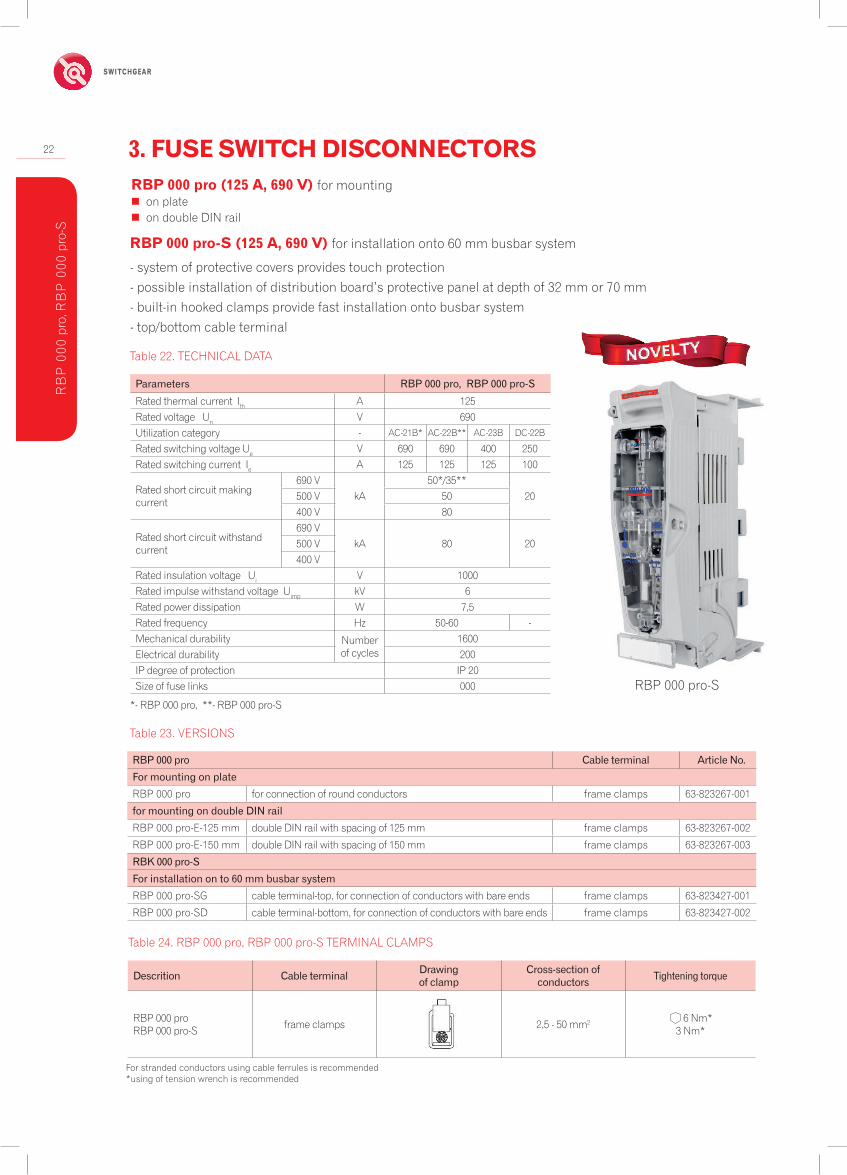
Table 22. TECHNICAL DATA
Table 23. VERSIONS
RBP 000 pro (125 A, 690 V) for mounting � on plate � on double DIN rail
Parameters RBP000pro,RBP000pro-S
Rated thermal current Ith A 125Rated voltage Un V 690Utilization category - AC-21B* AC-22B** AC-23B DC-22B
Rated switching voltage Ue V 690 690 400 250Rated switching current Ie A 125 125 125 100
Rated short circuit making current
690 VkA
50*/35**20500 V 50
400 V 80
Rated short circuit withstand current
690 VkA 80 20500 V
400 VRated insulation voltage Ui V 1000Rated impulse withstand voltage Uimp kV 6Rated power dissipation W 7,5Rated frequency Hz 50-60 -Mechanical durability Number
of cycles1600
Electrical durability 200IP degree of protection IP 20Size of fuse links 000
Descrition Cableterminal Drawingofclamp
Cross-sectionofconductors Tighteningtorque
RBP 000 proRBP 000 pro-S frame clamps 2,5 - 50 mm2 6 Nm*
3 Nm*
For stranded conductors using cable ferrules is recommended*using of tension wrench is recommended
RBP 000 pro-S (125 A, 690 V) for installation onto 60 mm busbar system
Table 24. RBP 000 pro, RBP 000 pro-S TERMINAL CLAMPS
- system of protective covers provides touch protection- possible installation of distribution board’s protective panel at depth of 32 mm or 70 mm- built-in hooked clamps provide fast installation onto busbar system - top/bottom cable terminal
RBP 000 pro-S
RB
P 0
00 p
ro, R
BP
000
pro
-S
3. FUSE SWITCH DISCONNECTORS
*- RBP 000 pro, **- RBP 000 pro-S
ENERGY SAFELY SWITCHED
23
70 mm
32 mm
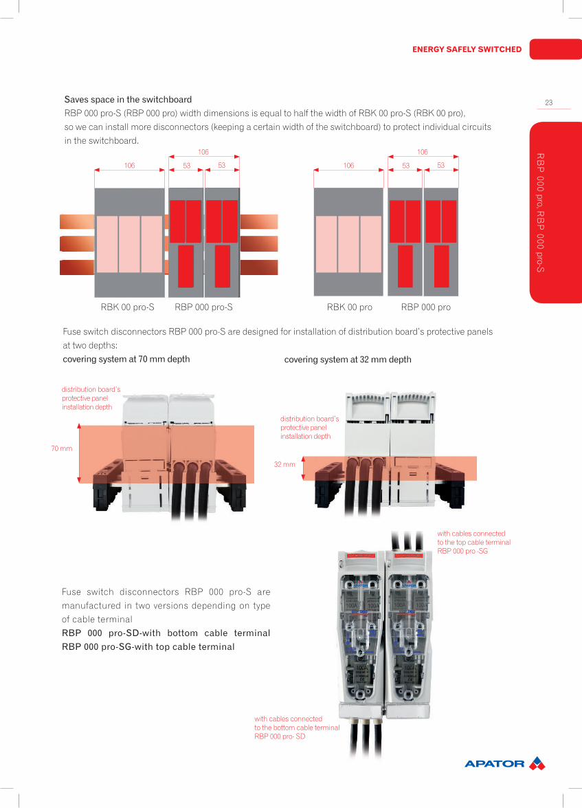
Fuse switch disconnectors RBP 000 pro-S are designed for installation of distribution board’s protective panels at two depths:coveringsystemat70mmdepth coveringsystemat32mmdepth
distribution board’s protective panel installation depth
with cables connected to the top cable terminalRBP 000 pro -SG
with cables connected to the bottom cable terminalRBP 000 pro- SD
Fuse switch disconnectors RBP 000 pro-S are manufactured in two versions depending on type of cable terminalRBP 000 pro-SD-with bottom cable terminalRBP000pro-SG-withtopcableterminal
distribution board’s protective panel installation depth
SavesspaceintheswitchboardRBP 000 pro-S (RBP 000 pro) width dimensions is equal to half the width of RBK 00 pro-S (RBK 00 pro), so we can install more disconnectors (keeping a certain width of the switchboard) to protect individual circuits in the switchboard.
106
106
53 53 106
106
53 53
RBK 00 pro-S RBP 000 pro-S RBK 00 pro RBP 000 pro
RB
P 000 pro, R
BP
000 pro-S

24
SWITCHGEAR
Fuse switch disconnector RBP 000 pro-S has special cavity in it’s main base encasing busbar system’s support.
cavity for busbar system’s support
It is possible to install microswitchindicating position open/close fuse switch disconnectors.
hole for leading of wires connected to microswitch
Fuse switch disconnector RBP 000 pro - E 125 mm for mounting on double DIN rail
RBP 000 promounting on plate
RB
P 0
00 p
ro, R
BP
000
pro
-S
ENERGY SAFELY SWITCHED
25
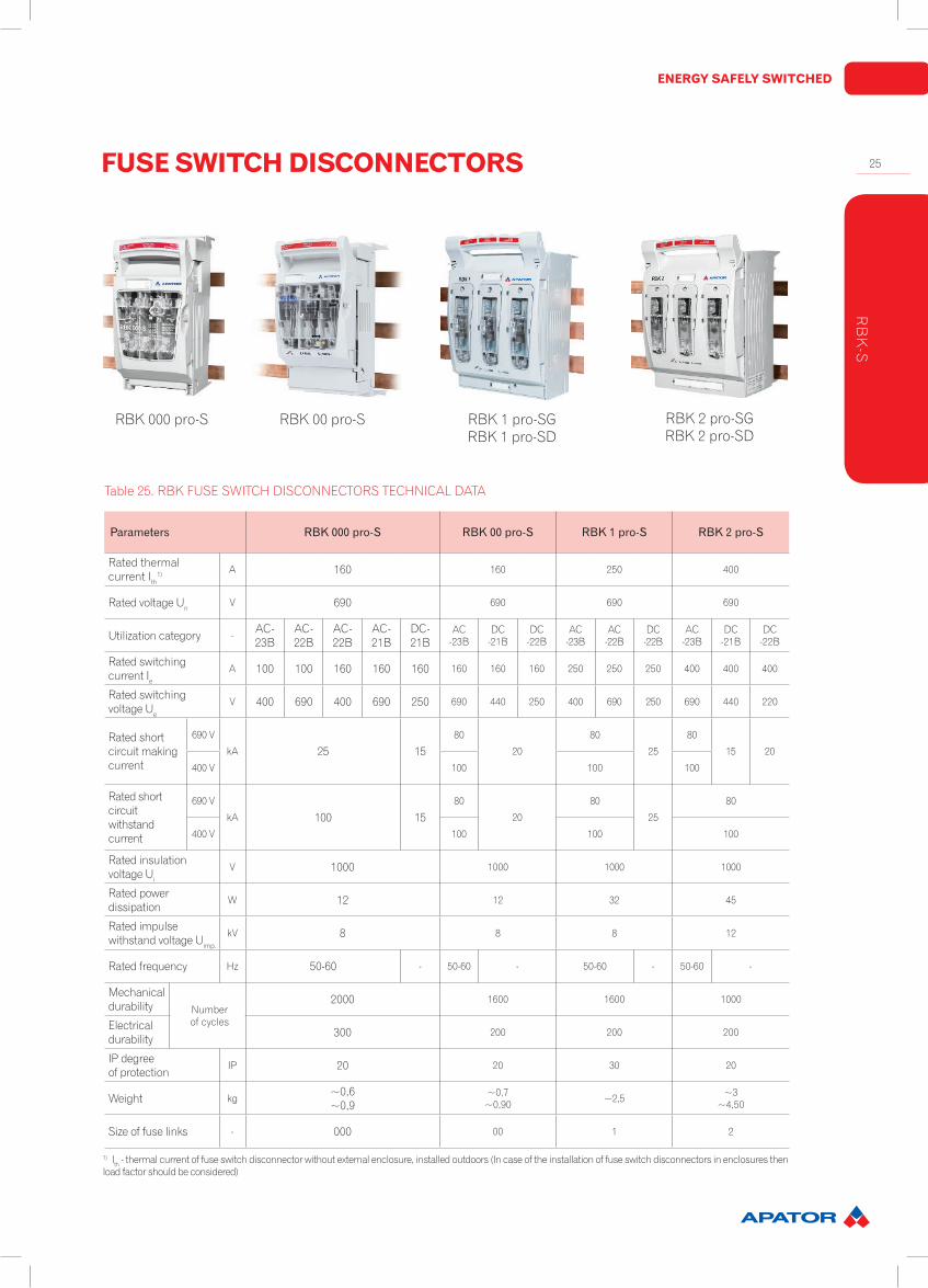
Table 25. RBK FUSE SWITCH DISCONNECTORS TECHNICAL DATA
1) Ith - thermal current of fuse switch disconnector without external enclosure, installed outdoors (In case of the installation of fuse switch disconnectors in enclosures then load factor should be considered)
Parameters RBK000pro-S RBK00pro-S RBK1pro-S RBK2pro-S
Rated thermalcurrent Ith
1) A 160 160 250 400
Rated voltage Un V 690 690 690 690
Utilization category -AC-23B
AC-22B
AC-22B
AC-21B
DC-21B
AC-23B
DC-21B
DC-22B
AC-23B
AC-22B
DC-22B
AC-23B
DC-21B
DC-22B
Rated switchingcurrent Ie
A 100 100 160 160 160 160 160 160 250 250 250 400 400 400
Rated switchingvoltage Ue
V 400 690 400 690 250 690 440 250 400 690 250 690 440 220
Rated shortcircuit makingcurrent
690 V
kA 25 1580
20
80
25
80
15 20
400 V 100 100 100
Rated shortcircuit withstandcurrent
690 V
kA 100 1580
20
80
25
80
400 V 100 100 100
Rated insulationvoltage Ui
V 1000 1000 1000 1000
Rated powerdissipation
W 12 12 32 45
Rated impulsewithstand voltage Uimp.
kV 8 8 8 12
Rated frequency Hz 50-60 - 50-60 - 50-60 - 50-60 -
Mechanicaldurability Number
of cycles
2000 1600 1600 1000
Electricaldurability 300 200 200 200
IP degree of protection
IP 20 20 30 20
Weight kg~0,6~0,9
~0,7~0,90 ~2,5 ~3
~4,50
Size of fuse links - 000 00 1 2
RBK 00 pro-S RBK 1 pro-SGRBK 1 pro-SD
RBK 2 pro-SGRBK 2 pro-SD
RBK 000 pro-S
FUSE SWITCH DISCONNECTORS
RB
K-S

26
SWITCHGEAR
Item Forinstallationonto60mmbusbarsystem Cableterminal ArticleNo.
RBK000pro-S
RBK 000 pro-SD Cable terminal – bottom, for connection of round conductors S-bridge clamps 63-823234-031
RBK 000 pro-SG Cable terminal – top, for connection of round conductors S-bridge clamps 63-823234-011
RBK 000 pro-SD-M Cable terminal – bottom, for connection of conductors with lug terminals M8 screws 63-823234-041
RBK 000 pro-SG-M Cable terminal – top, for connection of conductors with lug terminals M8 screws 63-823234-021
RBK00pro-S
RBK 00 pro-SG-M cable terminal – bottom, for connection of conductors with lug terminals M8 screws 63-823259-121
RBK 00 pro-SD-M cable terminal – top, for connection of conductors with lug terminals M8 screws 63-823259-141
RBK 00 pro-SG-R cable terminal-top, for connection of conductors with bare ends frame clamps 63-823259-151
RBK 00 pro-SD-R cable terminal-bottom, for connection of conductors with bare ends frame clamps 63-823259-161
RBK1pro-S
RBK 1 pro-SG 60 Top cable terminals, for connection of round conductors S-bridge clamps 63-811750-011
RBK 1 pro-SD 60 Bottom cable terminals, for connection of round conductors S-bridge clamps 63-811750-021
RBK 1 pro-SG-M 60 Bottom cable terminals, for connection of sector-shaped conductors V- clamps 63-811750-051
RBK 1 pro-SD-M 60 Bottom cable terminals, for connection of conductors withlug terminals Screws 63-811750-061
RBK 1 pro-SG-V 60 Top cable terminals, for connection of sector-shaped conductors V-clamps 63-811750-091
RBK 1 pro-SD-V 60 Bottom cable terminals, for connection of sector-shaped conductors V-clamps 63-811750-101
RBK2pro-S
RBK 2 pro-M-SD 60 Bottom cable terminals, for connection of conductors with lug terminals M10 screws 63-811686-061
RBK 2 pro-M-SG 60 Top cable terminals, for connection of conductors with lug terminals M10 screws 63-811686-051
RBK 2 pro-V-SD 60 Bottom cable terminals, for connection of sector-shaped conductors V-clamps 63-811686-101
RBK 2 pro-V-SG 60 Top cable terminals, for connection of sector-shaped conductors V-clamps 63-811686-091
RBK 2 pro-2V-SD 60 Bottom cable terminals, for connection of sector-shaped conductors double V- clamps 63-811686-141
RBK 2 pro-2V-SG 60 Top cable terminals, for connection of sector-shaped conductors double V- clamps 63-811686-131
Tabela 26. VERSIONS
RBK can be made with electronic fuse monitoring module.Details and dimensions of RBK are contained in SWITCHGEAR PRODUCT CATALOGUE.
RB
K-S
ENERGY SAFELY SWITCHED
27NOTES
NO
TES
www.apator.com
SWITCHGEAR
ELECTRICITY METERS
SENSORS
MINING EQUIPMENT
HEAT METERS
METERING SOLUTIONS
SURGE ARRESTERS
WATER METERS
IT SYSTEMS
INDUSTRIAL AUTOMATION
GAS METERS
EN.00030/2014
thepublicationisonlyforinformationpurposesanditisnottheofferinunderstandingofthelaw