Embed Size (px)
Citation preview

BULLETIN NO.SERVICE PARTS LIST 54-26-2830
Nov. 2018REVISED BULLETIN DATE
WIRING INSTRUCTION
FIG. PART NO. DESCRIPTION OF PART NO. REQ. 1 06-82-4000 M5 x 40mm Pan Hd. ST T-20 Screw (4) 2 14-30-0840 Front Housing Assembly with Bushing (1) 3 45-88-2005 Front Housing Washer (1) 4 44-90-4530 Friction Ring (1) 5 34-40-0900 O-Ring (1) 6 --------------- 1/2" Square Anvil (1) 7 02-02-0251 6.6mm Steel Ball (3) 8 43-81-0310 Hammer (1) 9 02-02-2050 3/16" Steel Ball (28) 10 45-88-2015 Washer (1) 11 40-50-1925 Hammer Spring (1) 12 36-10-0910 Cam Shaft (1) 14 32-62-0700 Planet Gear (3) 15 44-60-1960 Planet Pin (3) 16 45-88-2020 Washer (1) 17 02-04-0375 Ball Bearing (1) 18 34-60-5002 Retaining Ring (1) 19 32-65-0375 Ring Gear (1) 20 44-66-1650 Rear Gear Case (1) 28 34-60-0011 Retaining Ring (1) 29 02-04-0155 Ball Bearing (1) 34 06-82-4001 M4 x 22mm Pan Hd. ST T-20 Screw (5) 35 06-82-4002 M4 x 35mm Pan Hd. ST T-20 Screw (2) 36 06-82-4003 M4 x 16mm Pan Hd. ST T-20 Screw (4) 38 --------------- Housing Cover - Right (1) 39 45-30-0255 Rubber Slug (4) 40 45-24-0022 Forward / Reverse Shuttle (1)
See Page 2H96ASTARTING SERIAL NO. 2767-20CATALOG NO.
M18 FUEL™ 1/2" SQUARE IMPACT WRENCH with friction ringSPECIFY CATALOG NO. AND SERIAL NO. WHEN ORDERING PARTS
FIG. PART NO. DESCRIPTION OF PART NO. REQ. 44 --------------- Housing Support - Left with Metal Pin (1) 54 12-20-2810 Service Nameplate (1) 55 43-44-1420 Gasket (1) 56 42-70-5151 Belt Hook (1) 57 06-82-0130 6-32 x 5/16 Pan Hd. T-15 Machine Screw (1) 60 42-06-2760 1/2" Square Anvil Assy. w/ Friction Ring (1) 61 14-46-2820 Impacting Assembly (1) 62 31-44-3160 Housing Assembly (1) 63 14-20-0930 Electronics Assembly (1) 64 16-01-0400 Rotor/End Cap Assembly (1) 65 45-24-0450 Speed Switch Assembly (1) 66 42-55-2820 Carrying Case (1)
0EXAMPLE: Component Parts (Small #) Are IncludedWhen Ordering The Assembly (Large #).
00
MILWAUKEE TOOL l www.milwaukeetool.com13135 W. Lisbon Road, Brookfield, WI 53005
Drwg. 3
8
9(28x)
10
11
12
7(2x)
15(3x)
16
17
14(3x)
55
18
19
20
40
39(4x)
28
29
34(4x)
63
44
54
34(1x)
38
35(2x)
36(4x)
57
56
3
4
5
6
7
65
2
1(4x)
2829 64
4 5 6 7 60
35 36 3839 44 54 62
61 7 8 9 10 1112 14 15 16 17
PCBA
63
65 44
As an aid for servicing, the Speed Switch Assembly#65 should be mounted onto the PCBA first and than carefully installed together into the Left Hous-ing Halve #44.
66
39
Rubber Slugs are (2x) per handle halve (4 total)
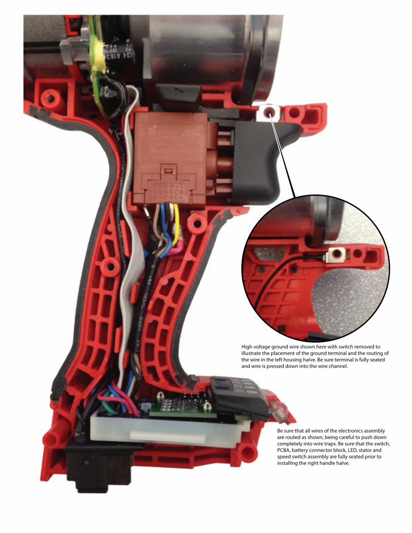
High voltage ground wire shown here with switch removed to illustrate the placement of the ground terminal and the routing of the wire in the left housing halve. Be sure terminal is fully seated and wire is pressed down into the wire channel.
Be sure that all wires of the electronics assembly are routed as shown, being careful to push down completely into wire traps. Be sure that the switch, PCBA, battery connector block, LED, stator and speed switch assembly are fully seated prior to installing the right handle halve.