Embed Size (px)
Citation preview

Rockwell Automation 5-29
Bulletin CEFB1Motor Protection
5
Table of ContentsDescription Page Description PageOverview . . . . . . . . . . . . . . . . . . . . . . . . . . . . . . . . . . . . . . . . . . 5-30
Type Description . . . . . . . . . . . . . . . . . . . . . . . . . . . . . . . . . . . . 5-32
Product Selection . . . . . . . . . . . . . . . . . . . . . . . . . . . . . . . . . . . 5-33
Accessories . . . . . . . . . . . . . . . . . . . . . . . . . . . . . . . . . . . . . . . . 5-34
Specifications . . . . . . . . . . . . . . . . . . . . . . . . . . . . . . . . . . . . . . 5-36
Weight . . . . . . . . . . . . . . . . . . . . . . . . . . . . . . . . . . . . . . . . . . . 5-37
Approvals . . . . . . . . . . . . . . . . . . . . . . . . . . . . . . . . . . . . . . . . 5-37
Dimensions . . . . . . . . . . . . . . . . . . . . . . . . . . . . . . . . . . . . . . . . 5-38
Bulletin CEFB1 Electronic Overload Relay
• CEFB1-11 (0.5) 20…180 A
• CEFB1-12 (0.5) 20…180 A
• CEFB1-41 160…400 A
• CEFB1-42 160…400 A
• CEFB1-52 160…630 A
Bulletin CEFB1Motor Protection
5-30 Rockwell Automation
5
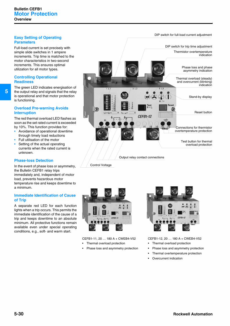
Overview
Easy Setting of Operating ParametersFull-load current is set precisely withsimple slide switches in 1 ampereincrements. Trip time is matched to themotor characteristics in two-secondincrements. This ensures optimal utilization for all motor types.
Controlling Operational ReadinessThe green LED indicates energisation ofthe output relay and signals that the relayis operational and that motor protectionis functioning.
Overload Pre-warning Avoids InterruptionThe red thermal overload LED flashes as soon as the set rated current is exceeded by 10%. This function provides for:• Avoidance of operational downtime
through timely load reductions• Full utilisation of the motor• Setting of the actual operating
currents when the rated current is unknown.
Phase-loss DetectionIn the event of phase loss or asymmetry, the Bulletin CEFB1 relay trips immediately and, independent of motor load, prevents hazardous motor temperature rise and keeps downtime to a minimum.
Immediate Identification of Cause of TripA separate red LED for each functionlights when a trip occurs. This permits theimmediate identification of the cause of atrip and keeps downtime to an absoluteminimum. All protective functions remainavailable even under special operatingconditions, e.g., soft- and warm start.
DIP switch for full-load current adjustment
Reset button
Test button for thermaloverload protection
Control Voltage
Output relay contact connections
CEFB1-11, 20 … 180 A + CWEB4-V52
• Thermal overload protection
• Phase loss and asymmetry protection
CEFB1-12, 20 … 180 A + CWEB4-V52
• Thermal overload protection
• Phase loss and asymmetry protection
• Thermal overtemperature protection
• Overcurrent indication
Connections for thermistorovertemperature protection
Stand-by display
Thermal overload (steady)and overcurrent (blinking)
indication
Phase loss and phaseasymmetry indication
DIP switch for trip time adjustment
Thermistor overtemperatureindication

Rockwell Automation 5-31
Bulletin CEFB1Motor Protection
5
Overview
10 000
1 000
100
10
t [s]
1
0.30.8 1 2 3 4 6 8 10 • Ie
30 s
10 s
2 s
400
300
200
100
0
600
500
[A]
CEFB 1-12,CEFB1-11
CEFB 1-42,CEFB 1-41
CEFB 1-52
CEFB1-42, 160...400 A • Thermal overload protection
• Phase loss and asymmetry protection
• Thermal overtemperature protection
• Overcurrent indication
CEFB1-41, 160...400 A • Thermal overload protection
• Phase loss and asymmetry protection
Bulletin CERB1
remote reset
CEFB1-52, 160...630 A • Thermal overload protection
• Phase loss and asymmetry protection
• Thermal overtemperature protection
• Overcurrent indication
CELB1 indication module
Current range of the three Bulletin CEFB1 relay sizes
Time/current characteristic curves for shortest, normal, and longest tripping time
Bulletin CEFB1Motor Protection
5-32 Rockwell Automation
5
Type Description
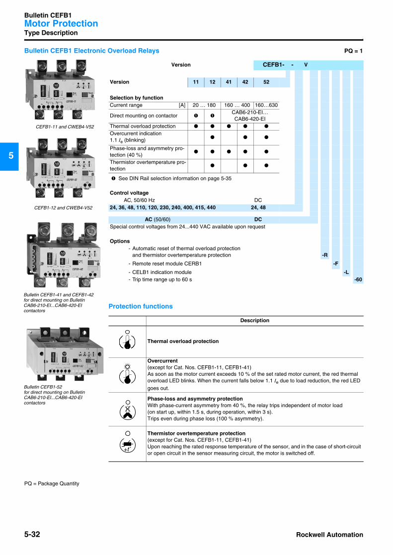
Bulletin CEFB1 Electronic Overload Relays PQ = 1
Protection functions
Version CEFB1- - V
Version 11 12 41 42 52
Selection by functionCurrent range [A] 20 … 180 160 … 400 160…630
Direct mounting on contactor ➊ ➊CAB6-210-EI…CAB6-420-EI
Thermal overload protection
Overcurrent indication 1.1 Ie (blinking)
Phase-loss and asymmetry pro-tection (40 %)
Thermistor overtemperature pro-tection
➊ See DIN Rail selection information on page 5-35
Control voltageAC, 50/60 Hz DC
24, 36, 48, 110, 120, 230, 240, 400, 415, 440 24, 48
AC (50/60) DCSpecial control voltages from 24...440 VAC available upon request
Options- Automatic reset of thermal overload protection
and thermistor overtemperature protection -R
- Remote reset module CERB1 -F
- CELB1 indication module -L- Trip time range up to 60 s -60
Description
Thermal overload protection
Overcurrent(except for Cat. Nos. CEFB1-11, CEFB1-41)As soon as the motor current exceeds 10 % of the set rated motor current, the red thermal overload LED blinks. When the current falls below 1.1 Ie due to load reduction, the red LED goes out.
Phase-loss and asymmetry protectionWith phase-current asymmetry from 40 %, the relay trips independent of motor load (on start up, within 1.5 s, during operation, within 3 s). Trips even during phase loss (100 % asymmetry).
Thermistor overtemperature protection(except for Cat. Nos. CEFB1-11, CEFB1-41)Upon reaching the rated response temperature of the sensor, and in the case of short-circuit or open circuit in the sensor measuring circuit, the motor is switched off.
CEFB1-12 and CWEB4-V52
Bulletin CEFB1-41 and CEFB1-42 for direct mounting on Bulletin CAB6-210-EI...CAB6-420-EI contactors
Bulletin CEFB1-52 for direct mounting on Bulletin CAB6-210-EI...CAB6-420-EI contactors
CEFB1-11 and CWEB4-V52
t˚+
PQ = Package Quantity
Rockwell Automation 5-33
Bulletin CEFB1Motor Protection
5
Product Selection
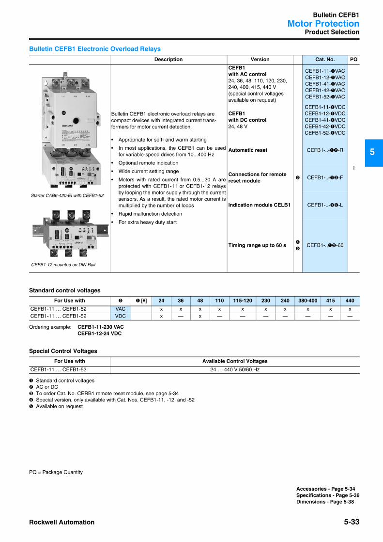
Bulletin CEFB1 Electronic Overload Relays
Standard control voltages
Ordering example: CEFB1-11-230 VACCEFB1-12-24 VDC
Special Control Voltages
➊ Standard control voltages➋ AC or DC ➌ To order Cat. No. CERB1 remote reset module, see page 5-34➍ Special version, only available with Cat. Nos. CEFB1-11, -12, and -52➎ Available on request
Description Version Cat. No. PQ
Bulletin CEFB1 electronic overload relays are compact devices with integrated current trans-formers for motor current detection.
• Appropriate for soft- and warm starting
• In most applications, the CEFB1 can be usedfor variable-speed drives from 10...400 Hz
• Optional remote indication
• Wide current setting range
• Motors with rated current from 0.5...20 A areprotected with CEFB1-11 or CEFB1-12 relaysby looping the motor supply through the currentsensors. As a result, the rated motor current ismultiplied by the number of loops
• Rapid malfunction detection
• For extra heavy duty start
CEFB1 with AC control24, 36, 48, 110, 120, 230, 240, 400, 415, 440 V(special control voltages available on request)
CEFB1-11-➊VACCEFB1-12-➊VACCEFB1-41-➊VACCEFB1-42-➊VACCEFB1-52-➊VAC
1
CEFB1 with DC control24, 48 V
CEFB1-11-➊VDCCEFB1-12-➊VDCCEFB1-41-➊VDCCEFB1-42-➊VDCCEFB1-52-➊VDC
Automatic reset CEFB1-..-➊➋-R
Connections for remote reset module
➌ CEFB1-..-➊➋-F
Indication module CELB1 CEFB1-..-➊➋-L
Timing range up to 60 s➍
➎CEFB1-..➊➋-60
For Use with ➋ ➊ [V] 24 36 48 110 115-120 230 240 380-400 415 440
CEFB1-11 … CEFB1-52 VAC x x x x x x x x x xCEFB1-11 … CEFB1-52 VDC x — x — — — — — — —
For Use with Available Control Voltages
CEFB1-11 … CEFB1-52 24 … 440 V 50/60 Hz
Starter CAB6-420-EI with CEFB1-52
CEFB1-12 mounted on DIN Rail
PQ = Package Quantity
Accessories - Page 5-34Specifications - Page 5-36Dimensions - Page 5-38

Bulletin CEFB1Motor Protection
5-34 Rockwell Automation
5
Accessories
Add-on Modules
Mounting Materials
➊ Only Motor connection side, on supply side use CAB6-HA3
Description Version Cat. No. PQ
Indication Module• For front mounting on a control panel or MCC• 3 m connection cable with plug• Function status indication• Trips and alarms can be rest• IP54 protection
CELB1 1
Remote Reset Module• Trip reset from any location
Operating voltage24 … 48 V AC/DC
with external burden resistor- 8.2 kΩ, 4 W 110 … 230 V AC/DC- 22 kΩ, 10 W 240 … 440 V AC/DC
CERB11
Adapter for Remote Reset Module• For easy mounting of remote reset module on stand-
ard DIN Rail (EN 50 022-35) and G-Rail196-MTM 10
Description Version Cat. No. PQ
Transparent Front Cover CEFB1-PA 10
Main Terminal Cover • Set (2 pieces)
includes mounting materials
for 825-MVM / CWEB4-VSfor CWEB4-VS2for CEFB1-52
CAB6-HA1CAB6-HA2CAB6-HA3
1
Terminal Lug• Includes terminal and fixing screws
for CEFB1-11 and CEFB1-12
CEFB1-HD 6
Terminal Blocks• Set (2 pieces)
for 825-MVM, CWEB4-VSfor 825-MVM2, CWEB4-VS2for CEFB1-52 ➊
CAB6-HB1CAB6-HB2CAB6-HB3
1
A2 A1 98 97 96 95(-) (+) CEFB 1
r1 r2 r3
r1 r2 r3
CERB 1
rt
bl
RvUs
S1R
(-)(+)
CERB1 wiring diagram
PQ = Package Quantity
Product Selection - Page 5-33
Rockwell Automation 5-35
Bulletin CEFB1Motor Protection
5
Accessories
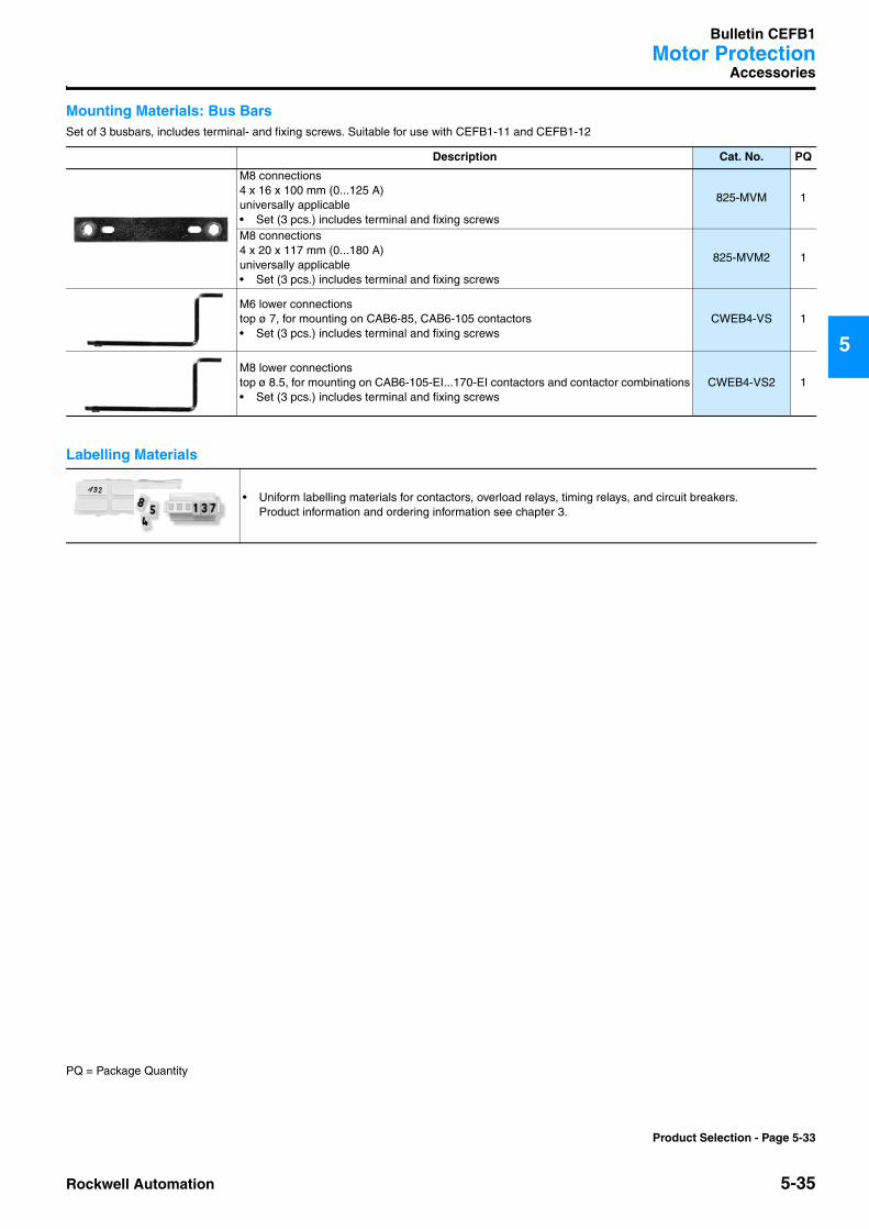
Mounting Materials: Bus BarsSet of 3 busbars, includes terminal- and fixing screws. Suitable for use with CEFB1-11 and CEFB1-12
Labelling Materials
Description Cat. No. PQ
M8 connections4 x 16 x 100 mm (0...125 A)universally applicable• Set (3 pcs.) includes terminal and fixing screws
825-MVM 1
M8 connections4 x 20 x 117 mm (0...180 A)universally applicable• Set (3 pcs.) includes terminal and fixing screws
825-MVM2 1
M6 lower connectionstop ø 7, for mounting on CAB6-85, CAB6-105 contactors• Set (3 pcs.) includes terminal and fixing screws
CWEB4-VS 1
M8 lower connectionstop ø 8.5, for mounting on CAB6-105-EI...170-EI contactors and contactor combinations• Set (3 pcs.) includes terminal and fixing screws
CWEB4-VS2 1
• Uniform labelling materials for contactors, overload relays, timing relays, and circuit breakers.Product information and ordering information see chapter 3.
PQ = Package Quantity
Product Selection - Page 5-33
Bulletin CEFB1Motor Protection
5-36 Rockwell Automation
5
Specifications
General
Supply voltage failureIn the event of a supply voltage failure, the output relay resets and thestand-by indicator goes out. The actual status is stored for 30 minutes.When the supply voltage is restored, the output relay reverts to its originalstate.
ResetManualThe reset button resets all protection functions. Resetting from any lo-cation is possible with the CERB1 remote reset module.AutomaticAutomatic resetting of thermal overload and thermistor overtemperaturefunctions is an optional feature. All other protection functions must bereset manually.
Test button for thermal overload protectionPressing the test button will verify thermal tripping operation time at 6xIewithout the motor being connected. The test button must be held forlonger than the set trip time t6xIe.
Device installation and commissioningThe operating instructions enclosed with the device provide all of theinformation necessary to set and commission it.
Surface mountingCEFB1-11 Snap-on fixing to standard DIN Rail orCEFB1-12 Screw fixing
CEFB1-41 Screw fixingCEFB1-42 Screw fixingCEFB1-52 Screw fixingMounting position:optional
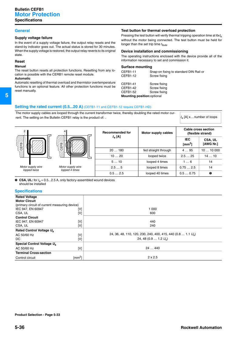
Setting the rated current (0.5...20 A) (CEFB1-11 and CEFB1-12 require CEFB1-HD)
➊ CSA, UL: for Ie = 0.5...2.5 A, only factory-assembled wound devices should be installed
Specifications
The motor supply cables are looped through the current transformer twice, thereby doubling the rated motor cur-rent. The setting on the Bulletin CEFB1 relay is the product of: .
Recommended forIe [A]
Motor supply cablesCable cross section
(flexible strand)
IEC
[mm2]CSA, UL
[AWG Nr.]
20 … 180 fed straight through 4 … 95 10 … 10 000
10 … 20 looped twice 2.5 … 25 14 … 10
5 … 10 looped 4 times 1 … 6 14
2.5 … 5 looped 8 times 0.75 … 2.5 14
0.5 … 2.5 looped 40 times 0.5 … 0.75 ➊
Ie [A] x… number of loops
CE
FB
2
CE
FB
4
Motor supply wirelopped twice
Motor supply wirelopped 4 times
Rated VoltageMotor Circuit (primary circuit of current measuring device)IEC 947, EN 60947 [V]CSA, UL [V]
1 000600
Control CircuitIEC 947, EN 60947 [V]CSA, UL [V]
440240
Rated Control Voltage UsAC 50/60 Hz [V]DC [V]
24, 36, 48, 110, 120, 230, 240, 400, 415, 440 (0.8 … 1.1 Us)24, 48 (0.9 … 1.2 Us)
Special Control Voltage UsAC 50/60 Hz [V] 24 … 440
Terminal Cross-section
Control circuit [mm2] 2 x 2.5
Product Selection - Page 5-33
Rockwell Automation 5-37
Bulletin CEFB1Motor Protection
5
Specifications
Specifications
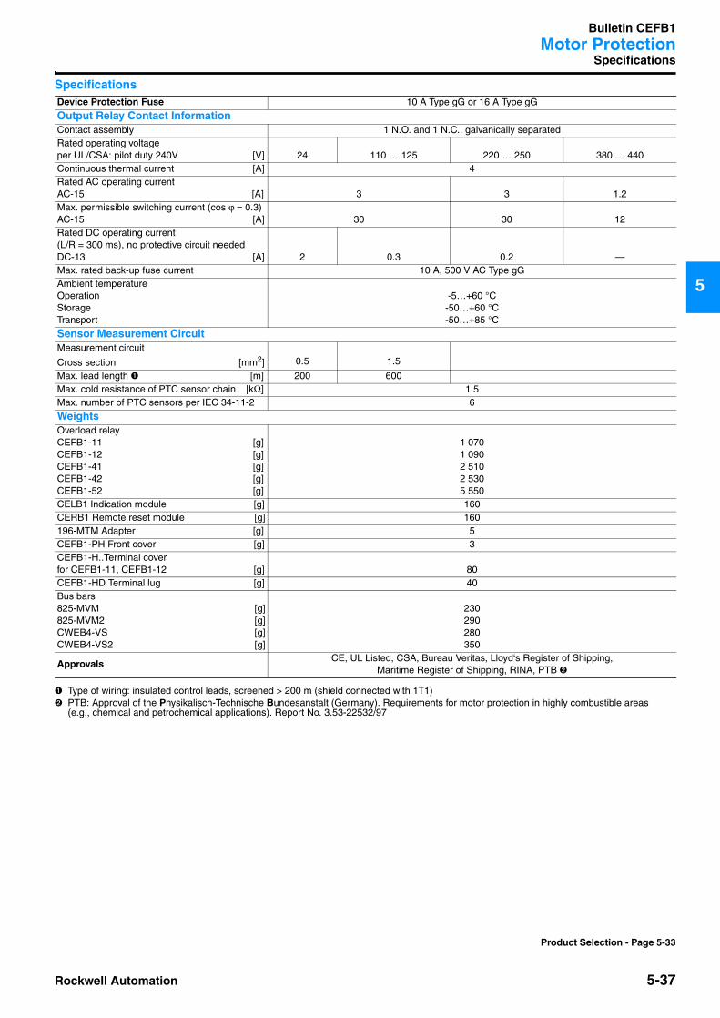
➊ Type of wiring: insulated control leads, screened > 200 m (shield connected with 1T1)➋ PTB: Approval of the Physikalisch-Technische Bundesanstalt (Germany). Requirements for motor protection in highly combustible areas
(e.g., chemical and petrochemical applications). Report No. 3.53-22532/97
Device Protection Fuse 10 A Type gG or 16 A Type gG
Output Relay Contact InformationContact assembly 1 N.O. and 1 N.C., galvanically separatedRated operating voltage per UL/CSA: pilot duty 240V [V] 24 110 … 125 220 … 250 380 … 440Continuous thermal current [A] 4Rated AC operating currentAC-15 [A] 3 3 1.2Max. permissible switching current (cos ϕ = 0.3) AC-15 [A] 30 30 12Rated DC operating current(L/R = 300 ms), no protective circuit needed DC-13 [A] 2 0.3 0.2 —Max. rated back-up fuse current 10 A, 500 V AC Type gGAmbient temperatureOperationStorageTransport
-5…+60 °C-50…+60 °C-50…+85 °C
Sensor Measurement CircuitMeasurement circuit
Cross section [mm2] 0.5 1.5
Max. lead length ➊ [m] 200 600Max. cold resistance of PTC sensor chain [kΩ] 1.5Max. number of PTC sensors per IEC 34-11-2 6
WeightsOverload relayCEFB1-11 [g]CEFB1-12 [g]CEFB1-41 [g]CEFB1-42 [g]CEFB1-52 [g]
1 0701 0902 5102 5305 550
CELB1 Indication module [g] 160CERB1 Remote reset module [g] 160196-MTM Adapter [g] 5CEFB1-PH Front cover [g] 3CEFB1-H..Terminal coverfor CEFB1-11, CEFB1-12 [g] 80CEFB1-HD Terminal lug [g] 40Bus bars 825-MVM [g]825-MVM2 [g]CWEB4-VS [g]CWEB4-VS2 [g]
230290280350
ApprovalsCE, UL Listed, CSA, Bureau Veritas, Lloyd‘s Register of Shipping,
Maritime Register of Shipping, RINA, PTB ➋
Product Selection - Page 5-33
Bulletin CEFB1Motor Protection
5-38 Rockwell Automation
5
Dimensions
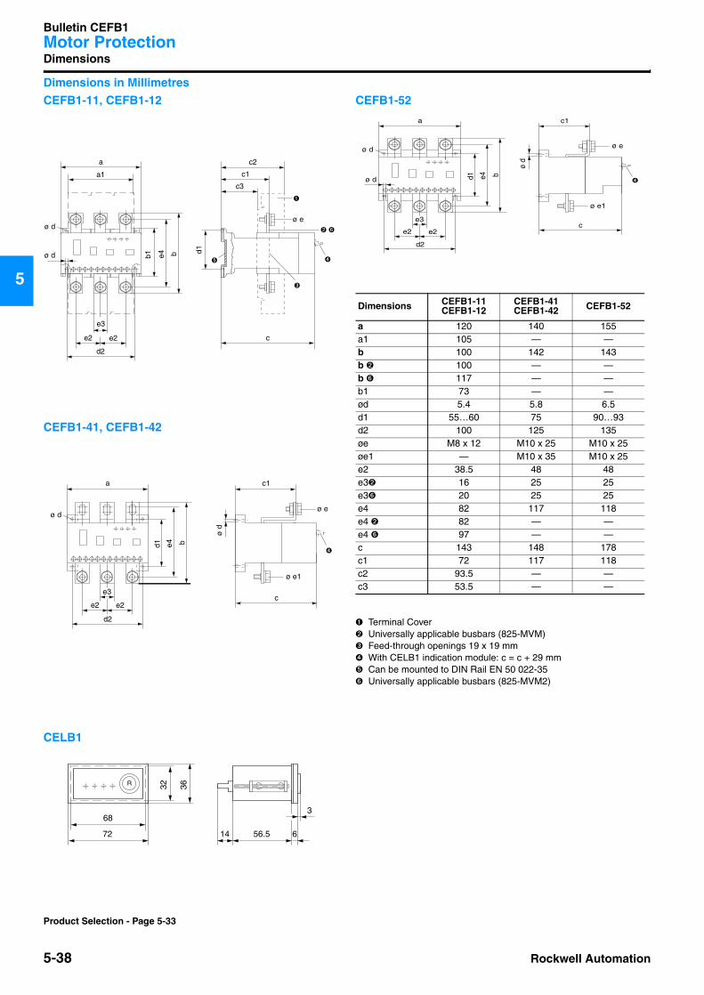
Dimensions in Millimetres
CEFB1-11, CEFB1-12
CEFB1-41, CEFB1-42
CELB1
CEFB1-52
➊ Terminal Cover➋ Universally applicable busbars (825-MVM)➌ Feed-through openings 19 x 19 mm➍ With CELB1 indication module: c = c + 29 mm➎ Can be mounted to DIN Rail EN 50 022-35➏ Universally applicable busbars (825-MVM2)
b1 e4 b
e2 e2
d2
a
ø d
a1
e3
c
➍
➌
c1
c3
d1
➎
ø e
➊
c2
➋ ➏
ø d
c
c1
d1 e4 b
a
➍
ø d
ø e
ø e1
ø d
e2e2
d2
e3
72
R 36
56.5 6
68
32
3
14
Dimensions CEFB1-11CEFB1-12
CEFB1-41CEFB1-42 CEFB1-52
a 120 140 155a1 105 — —b 100 142 143b ➋ 100 — —b ➏ 117 — —b1 73 — —ød 5.4 5.8 6.5d1 55…60 75 90…93d2 100 125 135øe M8 x 12 M10 x 25 M10 x 25øe1 — M10 x 35 M10 x 25e2 38.5 48 48e3➋ 16 25 25e3➏ 20 25 25e4 82 117 118e4 ➋ 82 — —e4 ➏ 97 — —c 143 148 178c1 72 117 118c2 93.5 — —c3 53.5 — —
ce2
c1
d1 e4 b
e2
d2
a
ø d
ø e
ø e1
ø d
ø d ➍
e3
Product Selection - Page 5-33