Embed Size (px)
Citation preview

Bulletin 899A
Capillary GC Inlet Liner Selection Guide
Four injection techniques – split, splitless, direct, and on-column – are used in capillary gas chromatography. Eachof these techniques, and their uses, are described in thisguide. Also described are various designs of inlet liners foreach injection technique, and injection-associated trouble-shooting tips are presented.
Key Words:l GC systems l GC sample deliveryl GC injection techniques l SPME optimization
Capillary Injection TechniquesCapillary gas chromatography is an inherently high efficiencychromatographic process, primarily due to the open, narrowinternal diameter of the columns used. To take full advantage ofthis high efficiency, a demanding and robust injection processmust be used. There are four primary injection techniques incapillary GC: split, splitless, direct, and on-column injection.These processes differ mechanically and in how they are per-formed, but all have the same goals: to introduce the sample onto the capillary column in as narrow a band as possible, toeffectively use the inherent efficiency of the column, and toensure that the portion of the sample that reaches the column isrepresentative of what was originally injected into the chromato-graphic system.
Split, splitless, and direct injection are vaporizing injections. Invaporizing injections, the carrier gas is introduced into thecapillary column through the injection port, which typicallycontains a glass inlet liner inside the heated metal injection block.Within the liner, the injected sample is vaporized, mixed withcarrier gas, and transferred to the capillary column.
In on-column injection, the sample is introduced directly into thecolumn inlet, typically as a liquid sample. The sample is vaporizedaccording to the temperature program of the chromatographicprocess (i.e., by the oven temperature), rather than by theinjection port temperature.
In the vaporizing injection techniques, the inlet liner is the pointof entry for the sample into the chromatographic process. It isextremely important that the appropriate inlet liner be used — itmust provide the injected sample with an inert, efficient path tothe capillary column. Both the design and the inertness of the lineraffect overall system performance. The liner should have a properexpansion volume, to allow vaporization of the injected liquidsample according to the chosen injection technique. It alsoshould be thoroughly deactivated, and free of contaminants, tominimize adsorption of active sample components. We recom-mend silanized inlet liners, and we use state-of-the-art silylation
techniques to deactivate all of the liners we make. Other parts ofthe injector and detector which come in contact with samples alsomust be inert and free of contaminants. Additionally, Supelcoliners can withstand temperatures of 300°C and higher.
In addition to the inlet liner, a key, and often overlooked, variablein performing the various injection techniques is the insertiondistance for introducing the column into the injector body. Thisdistance differs from manufacturer to manufacturer and amongthe four injection techniques. For successful chromatography, itis critical to follow the instrument manufacturer’s recommendedcolumn insertion distances.
Split InjectionSplit injection is a vaporizing-type injection and is probably themost commonly used injection technique. The technique isdesigned to reduce the amount of sample reaching the column.It is primarily used with highly concentrated samples, with percomponent quantities ranging from 0.1-20µg/µL. This tech-nique is used because capillary columns have a very small samplecapacity, relative to packed columns. Split injection provides thehighest efficiency and resolution of any of the injection tech-niques used in capillary GC, because high carrier gas velocities areused to transfer the sample to the column. Both split and splitlessinjection require specialized pneumatics systems designed for usewith capillary columns, ie., the so-called split/splitless injector.
In split injection, the sample is injected into a heated injection portand is vaporized in an area of very high carrier gas flow. As thevaporized sample flows through a tortuous path provided by thedesign of the inlet liner (splitter sleeve), it is mixed with carrier gas.
997-0067
T196899A ©1997 Sigma-Aldrich Co.

2 SUPELCOBulletin 899
Because of differences in the carrier gas flow rate to the columnand through the split vent, a small portion of the sample istransferred to the capillary column and the bulk of the sampleexits through the split vent port. The difference in flows estab-lishes the split ratio. The typical calculation for determining thesplit ratio and setting a split ratio of 100:1 is:
column flow + split vent flow+ septum purge flow
Split Ratio = —————————————————column flow
1cc/min + 97cc/min + 2cc/min= —————————————————
1cc/min
Split Ratio = 100:1
Because of the very high injector carrier gas flow velocities andrapid transfer of the sample to the column, which are importantin providing the high efficiencies for split injection, discriminationcan occur in split injection. This occurs when a sample containscomponents with a very broad molecular weight distribution.Due to slight differences in vaporization rates, the higher molecularweight components require slightly more time to vaporize andthus may not be thoroughly vaporized prior to the split. Anotherkey point of split injection is that since it is a vaporizing-typeinjection, thermally labile components can break down. It is alsoimportant to make the injection as rapidly as possible. If injectionis slow, band broadening will occur, reducing some of theinherent efficiency of this injection technique.
Baffle Liner — Turbulent flow is created by internal baffles.
Uses:l Generall Analytes with narrow range of boiling points
Benefits:l Moderately pricedl Can be cleaned
Disadvantages:l Nonvolatiles and septum fragments can get into the
columnl Inlet discrimination
Fritted Liner — A high surface area and complex flow paththrough a porous ceramic frit create the turbulent flow needed forsample volatilization.
Uses:
l General
Benefits:
l Minimizes sample discriminationl Effectively traps particles and nonvolatiles
Disadvantages:
l Expensivel Ceramic frit can adsorb analytes or contribute to their
decompositionl Cannot be cleaned easily
Cup Liner — Complex flow path enhances volatilization of highmolecular weight compounds. Can be packed with wool to trapnonvolatiles.
Uses:l High analyte concentrationsl High molecular weight analytesl Large sample volumes (up to 5µL)l Dual column applications
Benefits:l Inlet discrimination is minimizedl Design enhances resolution
Disadvantages:l Expensivel Hard to clean
Straight Liner Packed with Wool — The large expansionvolume and surface area of wool enhance the mixing andvaporization of the sample and trap septum fragments andnonvolatiles in dirty samples.
Uses:l General and autosampler usel Use with a wide range of molecular weight analytes
Benefits:l Easy to use (clean or replace dirty wool)l Inexpensive
Disadvantages:l Wool could adsorb analytes or contribute to
analyte decomposition
Inlet Liners for Split InjectionExamples of split injection inlet liners are shown in Figure A. Thecup liner is one of the most commonly used designs. Key designfeatures of all split injection liners provide rapid, efficient heattransfer to the sample so it is properly vaporized, and a large-volume sample expansion area followed by a constricted area. Inthe expansion area, the sample vaporizes and begins to mix withcarrier gas. Turbulent flow is established in the constricted area,to aid in mixing the vaporized sample before it reaches the splitpoint and column inlet. Proper mixing ensures that a representa-tive part of the sample enters the column. The design minimizesor prevents nonvolatile sample residue from reaching the col-umn, and the glass is inert to the sample components, to preventtheir adsorption or catalytical decomposition.
Figure A. Typical Inlet Liners for Split Injection
913-0241, 0260, 997-0126
Packed with Wool
With Baffle Cup (Unpacked)
3SUPELCOBulletin
Splitless InjectionSplitless injection is a sample-vaporizing injection techniquebased on using a split/splitless injection system in the non-splitting mode (i.e., with the split vent closed) for a part of theanalysis time. It is used primarily for trace level analysis of samplecomponents and when components elute closely after the sol-vent peak. Analyses incorporating this injection technique aretemperature programmed.
In splitless injection, a large amount of dilute sample is injectedinto a heated inlet liner, where it is vaporized, and a low flow ofcarrier gas sweeps most of the vaporized sample into the column.During the injection step in classical splitless injection, the columntemperature is kept 10°-20°C below the boiling point of thesample solvent matrix, so that the vaporized sample entering thecolumn recondenses or “focuses” in a tight band at the columninlet. Focusing is critical to a successful analysis. If the sample doesnot recondense in a tight band in the column inlet, the resultingpeak widths will reflect the volume of the injection port ratherthan the efficiency of the column. After approximately 1.5 to 2inlet liner volumes of carrier gas have passed through the inletliner and into the column, the split vent valve is opened and anyresidual sample remaining in the liner is vented through the splitvent port. Timing is important. The internal diameter of the inletliner, the carrier gas volumetric flow rate, and the sample volumeare a few of the key variables in determining the time to open thevalve. After a predetermined period of time, the oven tempera-ture is programmed upward, initiating sample component elu-tion through the column. The chromatographic process contin-ues as a typical temperature programmed analysis.
Sample introduction in splitless injection typically is slow, com-pared to the rapid injections used in split injection. A slowinjection is required because the inlet liner volume is limited – atypical 2 or 4mm ID splitless inlet liner (7 to 12cm in length) hasan internal volume between 0.2 and 1.5cc. Depending on theamount of sample introduced and the expansion coefficient ofthe solvent matrix, this internal volume potentially can be over-loaded, causing sample to be forced back into the carrier gas lines.Since, under proper conditions, the injected vaporized sample isrecondensed as a tight band at the column inlet, the analystshould not see any decrease in column efficiency due to the slowerinjection process.
Inlet liners for Splitless InjectionA splitless injection inlet liner typically is a simple, straight 2mmor 4mm ID tube (Figure B). Although it has none of the intricateconstrictions of sleeves for split injection, the design is importantto overall performance. A narrow internal diameter and corre-spondingly small internal volume are critical to transferring asmuch sample to the column as possible before opening the splitvent. If the internal volume is too large, an excessive purge timewill be needed to transfer sufficient sample to the column. Theinertness of the liner also is critical. A vaporized sample spendssignificantly longer time in a splitless injection liner than in a splitinjection liner, increasing the opportunity for adsorption of activesample components.
Direct InjectionDirect injection is a sample-vaporizing injection technique typi-cally used with packed column gas chromatographs that havebeen converted for use with wide bore capillary columns (ID >0.53mm). (For information on the conversion procedure, refer tothe Supelco catalog.) The technique is analogous to the flashvaporization injection technique used in packed column GC.Analyses can be either isothermal or temperature programmed.In direct injection, the sample is injected slowly into the heatedinlet liner, vaporized, then transported in its entirety to thecolumn. No splitting or specialized pneumatics are required, buta low-flow mass flow controller might be needed to ensure propercontrol of the low volumetric flow rates typically used with thesecolumns. Since all of the sample is transferred to the column,sample discrimination is eliminated, and direct injection is idealfor quantitative analysis. Thermally labile samples still can bedecomposed in this process, however.
In direct injection, it is important to use a slightly reducedinjection speed. The inlet liner has a limited volume and, if theliner is overloaded, the vaporizing sample could backflash ontothe face of the septum or into the carrier gas inlet lines, andrecondense. This will produce broad, tailing peaks, especially forthe solvent.
Straight Tube Configuration — Use a small internal volumefor slow manual injections and a larger volume for fast autosamplerinjections. For maximum reproducibility, wool-packed liners arerecommended for fast injections. Narrow-bore 0.75mm ID linerscan be used for low-volume gas or low-volume headspaceinjections, or with solid phase microextraction (see next page).
Benefits:
l Inexpensive
Disadvantages:
l Discrimination of high molecular weight compoundsl Decomposition of active compoundsl Sample flashback
Single- & Dual-Tapered Configurations — These inletliners feature a tapered restriction that helps vaporize the samplein the deactivated glass of the liner. This minimizes breakdownof compounds that are sensitive to the metal inlet surfaces presentin some GCs. The single taper can be packed with wool.
Benefits:
l High efficiencyl Reduced breakdown of active compoundsl Less sample flashback than straight liners
Disadvantages:
l Higher cost
Figure B. Typical Inlet Liners for Splitless Injection
913-0278, 0263, 0261, 0267
4mm ID2mm ID
Single Taper Dual Taper
4 SUPELCOBulletin 899
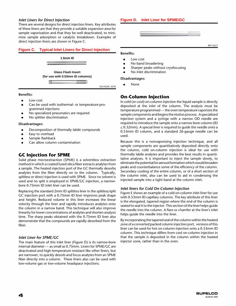
GC Injection for SPMESolid phase microextraction (SPME) is a solventless extractionmethod in which a coated fused silica fiber extracts analytes froma sample. The heated injection port of the GC thermally desorbsanalytes from the fiber directly on to the column. Typically,splitless or direct injection is used with SPME. Since no solvent isused and no split is employed in SPME/GC injection, a narrow-bore 0.75mm ID inlet liner can be used.
Replacing the standard 2mm ID splitless liner in the splitless/splitGC injection port with a 0.75mm ID liner improves peak shapeand height. Reduced volume in this liner increases the linearvelocity through the liner and rapidly introduces analytes ontothe column in a narrow band. This technique will also improvelinearity for lower concentrations of analytes and shorten analysistime. The sharp peaks obtained with the 0.75mm ID liner alsodemonstrate that the compounds are rapidly desorbed from thefiber.
Inlet Liner for SPME/GCThe main feature of this inlet liner (Figure D) is its narrow-boreinternal diameter — as small as 0.75mm. Liners for SPME/GC aredeactivated and high-temperature resistant like other liners, butare narrower, to quickly desorb and focus analytes from an SPMEfiber directly into a column. These liners also can be used withlow-volume gas or low-volume headspace injections.
On-Column InjectionIn cold (or cool) on-column injection the liquid sample is directlydeposited at the inlet of the column. The analysis must betemperature programmed — the oven temperature vaporizes thesample components and begins the elution process. A specializedinjection system and a syringe with a narrow OD needle arerequired to introduce the sample onto a narrow bore column (ID< 0.32mm). A special liner is required to guide the needle onto a0.53mm ID column, and a standard 26-gauge needle can beused.
Because this is a nonvaporizing injection technique, and allsample components are quantitatively deposited directly ontothe column, cold on-column injection is ideal for use withthermally labile analytes and provides the best results in quanti-tative analyses. It is important to inject the sample slowly, toeliminate the potential for aerosol formation which would broadenpeaks and counterbalance some of the efficiency of the column.Secondary cooling of the entire column, or of a short section ofthe column inlet, also can be used to aid in condensing theinjected sample into a tight band at the column inlet.
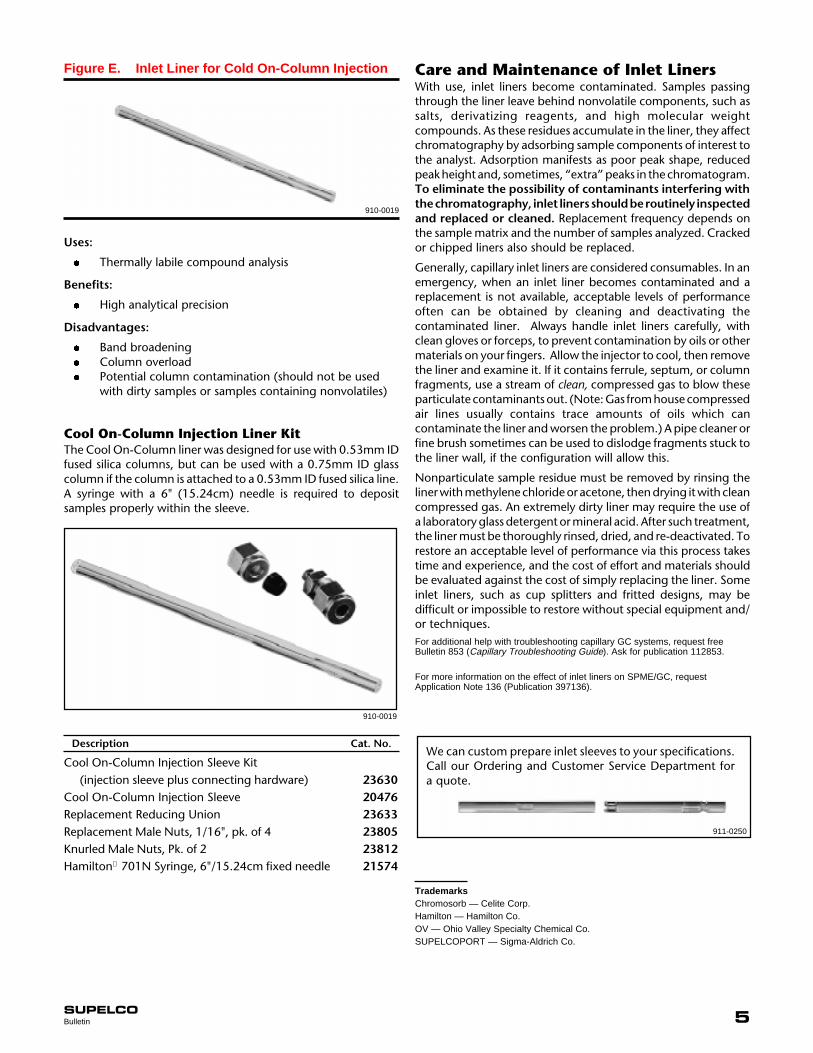
Inlet liners for Cold On-Column InjectionFigure E shows an example of a cold on-column inlet liner for usewith 0.53mm ID capillary columns. The key attribute of this lineris the elongated, tapered region where the end of the column isseated to seal it to the injector. This section of the liner helps guidethe needle into the column. A flare or chamfer at the liner's inlethelps guide the needle into the liner.
By incorporating the tapered seal of the column within the heatedzone of a converted packed column injection port, versions of thisliner can be used for hot on-column injection onto a 0.53mm IDcolumn. This technique differs from cool on-column injection inthat the sample is deposited in the column within the heatedinjector zone, rather than in the oven.
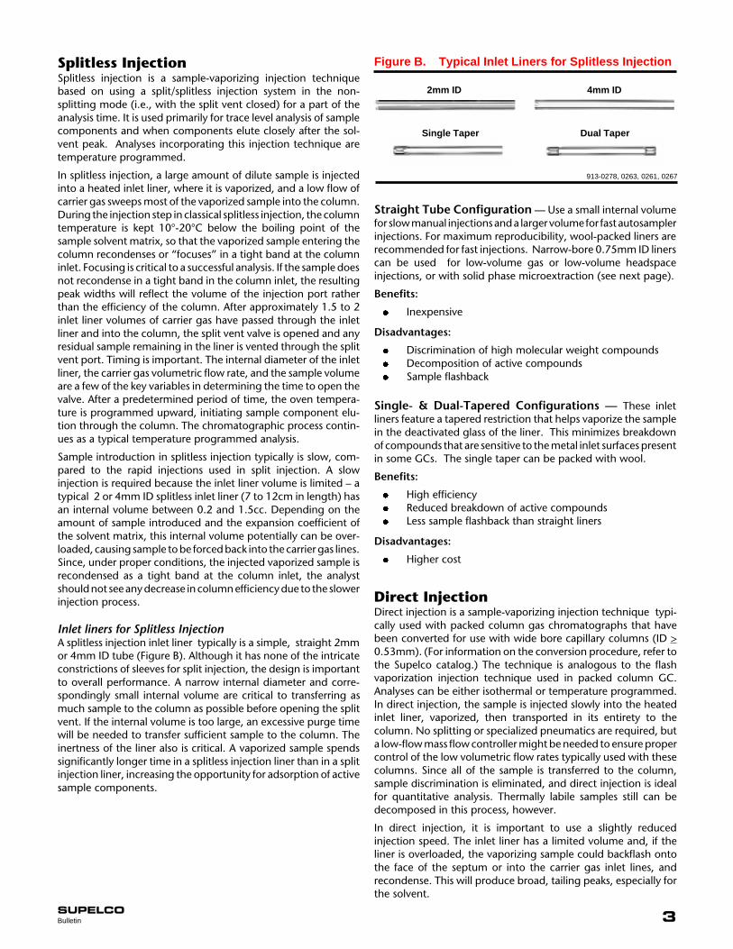
Figure C. Typical Inlet Liners for Direct Injection
1.5mm ID
Glass Flash Insert(for use with 0.53mm ID columns)
913-0245, 0276
Benefits:
l Low costl Can be used with isothermal- or temperature-pro-
grammed injectionsl No specialized pneumatics are requiredl No splitter discrimination
Disadvantages:
l Decomposition of thermally labile compoundsl Easy to overloadl Sample flashbackl Can allow column contamination
Inlet Liners for Direct InjectionThere are several designs for direct injection liners. Key attributesof these liners are that they provide a suitable expansion area forsample vaporization and that they be well deactivated, to mini-mize sample adsorption or catalytic breakdown. Examples ofdirect injection liners are shown in Figure C.
Benefits:
l Low costl No band broadeningl Sharper peaks without cryofocusingl No inlet discrimination
Disadvantages:
l None
997-0117
Figure D. Inlet Liner for SPME/GC
5SUPELCOBulletin
Care and Maintenance of Inlet LinersWith use, inlet liners become contaminated. Samples passingthrough the liner leave behind nonvolatile components, such assalts, derivatizing reagents, and high molecular weightcompounds. As these residues accumulate in the liner, they affectchromatography by adsorbing sample components of interest tothe analyst. Adsorption manifests as poor peak shape, reducedpeak height and, sometimes, “extra” peaks in the chromatogram.To eliminate the possibility of contaminants interfering withthe chromatography, inlet liners should be routinely inspectedand replaced or cleaned. Replacement frequency depends onthe sample matrix and the number of samples analyzed. Crackedor chipped liners also should be replaced.
Generally, capillary inlet liners are considered consumables. In anemergency, when an inlet liner becomes contaminated and areplacement is not available, acceptable levels of performanceoften can be obtained by cleaning and deactivating thecontaminated liner. Always handle inlet liners carefully, withclean gloves or forceps, to prevent contamination by oils or othermaterials on your fingers. Allow the injector to cool, then removethe liner and examine it. If it contains ferrule, septum, or columnfragments, use a stream of clean, compressed gas to blow theseparticulate contaminants out. (Note: Gas from house compressedair lines usually contains trace amounts of oils which cancontaminate the liner and worsen the problem.) A pipe cleaner orfine brush sometimes can be used to dislodge fragments stuck tothe liner wall, if the configuration will allow this.
Nonparticulate sample residue must be removed by rinsing theliner with methylene chloride or acetone, then drying it with cleancompressed gas. An extremely dirty liner may require the use ofa laboratory glass detergent or mineral acid. After such treatment,the liner must be thoroughly rinsed, dried, and re-deactivated. Torestore an acceptable level of performance via this process takestime and experience, and the cost of effort and materials shouldbe evaluated against the cost of simply replacing the liner. Someinlet liners, such as cup splitters and fritted designs, may bedifficult or impossible to restore without special equipment and/or techniques.For additional help with troubleshooting capillary GC systems, request freeBulletin 853 (Capillary Troubleshooting Guide). Ask for publication 112853.
For more information on the effect of inlet liners on SPME/GC, requestApplication Note 136 (Publication 397136).
Uses:
l Thermally labile compound analysis
Benefits:
l High analytical precision
Disadvantages:
l Band broadeningl Column overloadl Potential column contamination (should not be used
with dirty samples or samples containing nonvolatiles)
Cool On-Column Injection Liner KitThe Cool On-Column liner was designed for use with 0.53mm IDfused silica columns, but can be used with a 0.75mm ID glasscolumn if the column is attached to a 0.53mm ID fused silica line.A syringe with a 6" (15.24cm) needle is required to depositsamples properly within the sleeve.
910-0019
TrademarksChromosorb — Celite Corp.Hamilton — Hamilton Co.OV — Ohio Valley Specialty Chemical Co.SUPELCOPORT — Sigma-Aldrich Co.
Description Cat. No.
Cool On-Column Injection Sleeve Kit(injection sleeve plus connecting hardware) 23630
Cool On-Column Injection Sleeve 20476Replacement Reducing Union 23633Replacement Male Nuts, 1/16", pk. of 4 23805Knurled Male Nuts, Pk. of 2 23812Hamilton Ò 701N Syringe, 6"/15.24cm fixed needle 21574
Figure E. Inlet Liner for Cold On-Column Injection
910-0019
We can custom prepare inlet sleeves to your specifications.Call our Ordering and Customer Service Department fora quote.
911-0250

6 SUPELCOBulletin 899
Supelco inlet liners feature:
l High temperature silanization, to ensure inertnessl Consistent dimensions, tolerances and qualityl In-house manufacturing that meets or exceeds instru-
ment manufacturer’s specifications
These liners provide an exceptional value:
Save 20% on a pack of 5Save 35% on a pack of 25
We can also manufacture replacement liners for other instru-ments or unique liners from your own design. Just call for a quote.
Mfr./ Length x OD x ID l Mfr.
Inj. Type ( mm, unless otherwise noted) Applications Part # Qty. Cat. No.
Finnigan Models 4100 & 5100 (See HP liners for Model 9001)
For Model 51001 26340,01
High & low MW analytes 1005-40040 5 26340,0525 26340,25
87 x 6.6 x 4
For Model 51001 26341,01
Trace analytes 10005-40030 5 26341,0525 26341,25
87 x 6.6 x 2
For Model 41001 26342,01
Trace analytes 96100-20330 5 26342,0525 26342,25
112 x 4.5 x 3
Fisons/Carlo Erba Model 6000 Series
HS glass1 26320,01
Trace analytes 45300300 5 26320,0525 26320,25
79.5 x 5.5 x 2
HS glass1 26321,01
Trace analytes 45300400 5 26321,0525 26321,25
79.5 x 5.5 x 4
1 26323,01High & low MW analytes 45320010 5 26323,05
25 26323,25
99 x 5.5 x 4 (with slot)
1 26324,01Trace analytes 45320020 5 26324,05
25 26324,25
99 x 5.5 x 1.8 (with slot)
Hewlett-Packard Models 5880, 5980 Series, 6890, and Finnigan Model 9001
Cup (unpacked)1 20510,01
High & low MW analytes 18740-80190 5 20510,0525 20510,25
78.5 x 6.3
Cup (wool packed)1 20482,01
Dirty samples 18740-80190s 5 20482,0525 20482,25
78.5 x 6.3913-0259, 0255, 0244, 0271, 0268, 0274, 0242, 0260, 0250
Spl
itS
plitl
ess
Spl
itS
plitl
ess
sSupelco version has been modified to enhance performance. l Liners not shown to scale.

7SUPELCOBulletin
Hewlett-Packard (contd.)
Cup (packed w/ 10% OV®-1on Chromosorb®-W HP) Dirty samples 1 20551,01
Traps non-volatiles 18740-60840 5 20551,05Decreases discrimination 25 20551,25
78.5 x 6.3
Split/splitless1 20486,01
General 19251-60540 5 20486,05For 7673 autosampler 25 20486,25
78.5 x 6.3 x 4 (wool packed)
1 20513,01Trace analytes 18740-80220n 5 20513,05Samples <2µL 5181-8818 25 20513,25
78.5 x 6.5 x 2
Dual-tapered1 20485,01
Active analytes in 5181-3315 5 20485,05trace quantities 25 20485,25
78.5 x 6.5
Tapered (unpacked)1 20466,01
Active analytes in 5181-3316 5 20466,05trace quantities 25 20466,25
78.5 x 6.5
Tapered (wool packed)1 20478,01
General 5062-3587 5 20478,05For 7673 autosampler 25 20478,25
78.5 x 6.5
1 26375,01SPME no equivalent 5 26375,05Small volume 25 26375,25
78.5 x 6.3 x 0.75
1 20517,01Headspace & 18740-80200 5 20517,05purge/trap devices 25 20517,25
78.5 x 6.5 x 1.5
Perkin-Elmer Models 2000, 8000
wide bore1 26303,01
General purpose 0330-5181 5 26303,05Dirty samples 25 26303,25
100 x 5 x 4
narrow bore1 26304,01
Trace analytes 0330-5180 5 26304,0525 26304,25
100 x 5 x 2
Glass (unpacked)1 26306,01
For high linearity N600-2017 5 26306,0525 26306,25
88 x 2
Mfr./ Length x OD x ID l Mfr.
Inj. Type ( mm, unless otherwise noted) Applications Part # Qty. Cat. No.
913-0258, 0256, 0245, 0267, 0261, 0262, 994-0284, 0245, 0254, 0247, 0272
Spl
itS
plitle
ssP
TV
Inje
ctio
nD
irect
/SP
ME
Spi
tless
Spl
it
n Instrument manufacturer’s nondeactivated part number. lLiners not shown to scale.

8 SUPELCOBulletin 899
Perkin Elmer (contd.)
Glass (wool packed)1 26307,01
For high linearity N600-2096 5 26307,05Dirty samples 25 26307,25
88 x 2
Quartz (unpacked)1 26308,01
For high linearity N600-2036 5 26308,0525 26308,25
88 x 2
Auto System, Model 9000Split/Splitless Capillary Injector
1 26309,01General purpose N610-1052 5 26309,05
N612-1001* 25 26309,25
92 x 0.25" x 4
Packed (deactivated glass wool)1 26310,01
General purpose 5 26310,05Dirty samples 25 26310,25
92 x 0.25" x 4
1 26311,01Trace analysis N610-1372 5 26311,05
N612-1002* 25 26311,25
92 x 0.25" x 2
1 26312,01SPME 5 26312,05
24 26312,25
92 x 0.75 ID
Programmed Split/SplitlessInjection (PSS)
General purpose 1 26313,01for temperature N612-1004* 5 26313,05programmed analyses 25 26313,25
86 x 4 x 2
1 26314,01Trace analysis N612-1006* 5 26314,05
25 26314,25
86 x 4 x 1
1 26315,01Thermolabile analytes N610-1539 5 26315,05Trace analysis 25 26315,25
86 x 4 OD
Shimadzu Models 9A/AM/15A/16 with SPL-G9/15 Injectors
1 26330,01High & low MW analytes 221-25822-01 5 26330,05
25 26330,25
127 x 5 ID
Mfr./ Length x OD x ID l Mfr.
Inj. Type ( mm, unless otherwise noted) Applications Part # Qty. Cat. No.P
TV
Inje
ctio
nS
plit
Spl
itles
s/S
PM
ES
plit
Spl
itles
sO
n -
Col
umn
Spl
it
913-0282, 0243, 997-0125, 0126, 0116, 0117, 0121, 0118, 0119, 913-0253*Quantity available as made-to-order. lLiners not shown to scale.
9SUPELCOBulletin
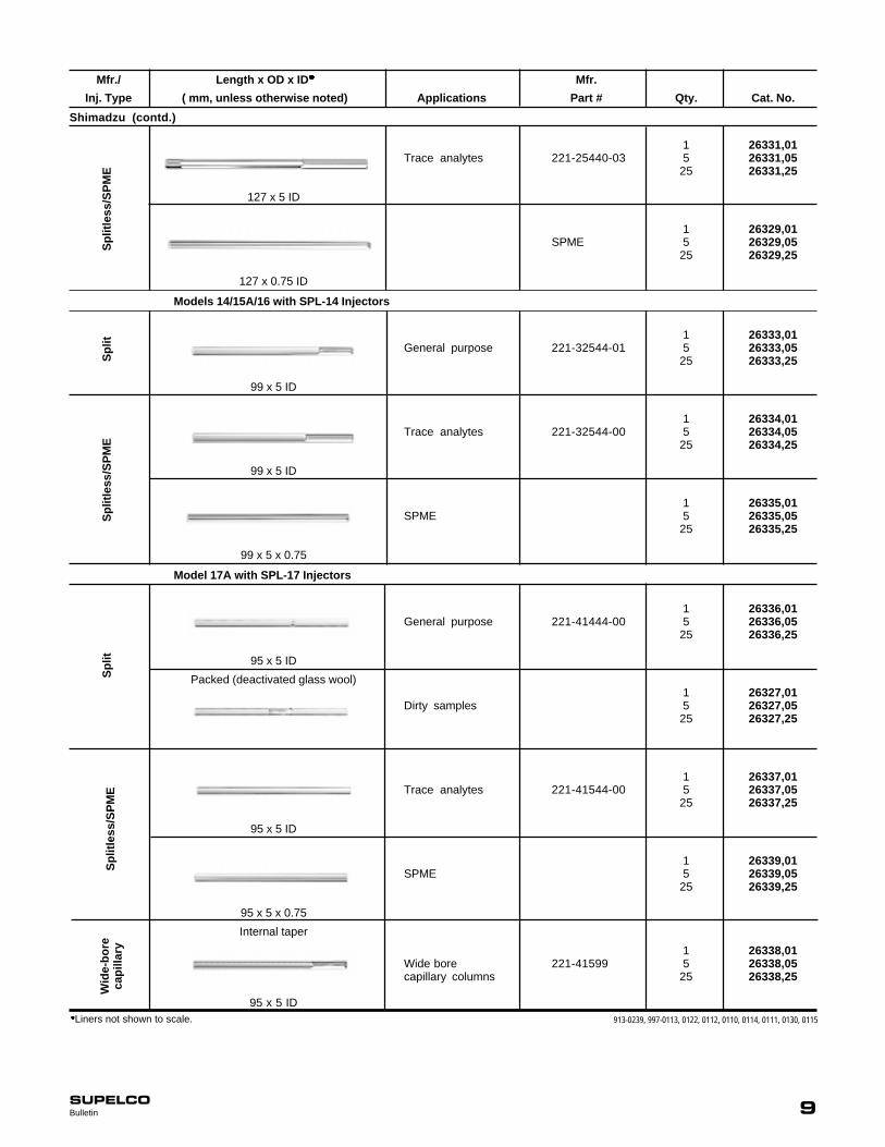
Shimadzu (contd.)
1 26331,01Trace analytes 221-25440-03 5 26331,05
25 26331,25
127 x 5 ID
1 26329,01SPME 5 26329,05
25 26329,25
127 x 0.75 ID
Models 14/15A/16 with SPL-14 Injectors
1 26333,01General purpose 221-32544-01 5 26333,05
25 26333,25
99 x 5 ID
1 26334,01Trace analytes 221-32544-00 5 26334,05
25 26334,25
99 x 5 ID
1 26335,01SPME 5 26335,05
25 26335,25
99 x 5 x 0.75
Model 17A with SPL-17 Injectors
1 26336,01General purpose 221-41444-00 5 26336,05
25 26336,25
95 x 5 ID
Packed (deactivated glass wool)1 26327,01
Dirty samples 5 26327,0525 26327,25
1 26337,01Trace analytes 221-41544-00 5 26337,05
25 26337,25
95 x 5 ID
1 26339,01SPME 5 26339,05
25 26339,25
95 x 5 x 0.75
Internal taper
1 26338,01Wide bore 221-41599 5 26338,05capillary columns 25 26338,25
95 x 5 ID
Mfr./ Length x OD x ID l Mfr.
Inj. Type ( mm, unless otherwise noted) Applications Part # Qty. Cat. No.S
plitl
ess/
SP
ME
Spl
itS
plitl
ess/
SP
ME
Spl
itS
plitl
ess/
SP
ME
Wid
e-bo
reca
pilla
ry
913-0239, 997-0113, 0122, 0112, 0110, 0114, 0111, 0130, 0115lLiners not shown to scale.

10 SUPELCOBulletin 899
Tremetrics
1 26354,01High & low MW analytes 116850-0001 5 26354,05
25 26354,25
102 x 6 x 4
1 26351,01High & low MW analytes 118075-0001 5 26351,05
25 26351,25
70 x 6 x 4
1 26352,01Trace analytes 116850-0003 5 26352,05
25 26352,25
84 x 6 x 2
1 26353,01Trace analytes 116850-0004 5 26353,05
25 26353,25
84 x 6 x 4
1 26350,01Trace analytes 118075-0002 5 26350,05
25 26350,25
70 x 6 x 2
Varian 1075/1077 Injectors
Unpacked1 26361,01
High & low MW analytes 16-000830-00n 5 26361,0525 26361,25
72 x 6.3
with frit1 20505,01
Dirty samples 16-000830-01n 5 20505,0501-900109-03 25 20505,25
72 x 6.3
Wool packed1 26360,01
Dirty samples 01-900109-01 5 26360,0525 26360,25
72 x 6.3
Packed w/ 10% OV-101 onChromosorb W HP 80/100
1 20555,01Complete vaporization 03-949809-00n 5 20555,05
25 20555,25
72 x 6.3 OD
with baffle
Analytes with close 16-000829-00n 1 20501,01 boiling points 01-900109-04 5 20501,05
25 20501,25
72 x 6.3 OD
Mfr./ Length x OD x ID l Mfr.
Inj. Type ( mm, unless otherwise noted) Applications Part # Qty. Cat. No.S
plit
Spl
itless
Spl
itS
plit
913-0270, 0279, 0278, 0263, 0277, 0273, 0240, 0257, 0248, 0241lLiners not shown to scale.
11SUPELCOBulletin
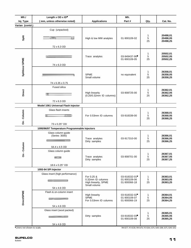
Varian (contd.)
Cup (unpacked)
1 20498,01High & low MW analytes 01-900109-02 5 20498,05
25 20498,25
72 x 6.3 OD
1 20502,01Trace analytes 03-949437-90n 5 20502,05
01-900109-05 25 20502,25
74 x 6.3 OD
1 26358,01SPME no equivalent 5 26358,05Small volume 25 26358,25
74 x 6.35 x 0.75
Fused silica1 26362,01
High linearity 03-908725-00 5 26362,05(0.25/0.32mm ID columns) 25 26362,25
72 x 6.3 OD
Model 1061 Universal Flash Injector
Glass flash inserts1 26368,01
For 0.53mm ID columns 03-918339-00 5 26368,0525 26368,25
73 x 0.25" OD
1095/96/97 Temperature Programmable Injectors
Glass column guide(Series 3000) 1 26366,01
Trace analytes 03-917310-00 5 26366,05Dirty samples 25 26366,25
64.4 x 4.5 OD
Glass column guide1 26367,01
Trace analytes 03-908701-00 5 26367,05Dirty samples 25 26367,25
18.6 x 0.25" OD
1093-94 SPI Injector
Glass insert (high performance)For 0.25 & 03-918332-01n 1 26363,010.32mm ID columns 01-900109-06 5 26363,05High linearity, SPME 01-900066-18 25 26363,25Small volume
54 x 4.6 OD
Flash & on-column insertHigh linearity 03-918332-02n 1 26364,01SPME 01-900109-07 5 26364,05For 0.53mm ID columns 01-900066-19 25 26364,25
54 x 4.6 OD
Glass insert (wool packed)1 26365,01
Dirty samples 03-918332-03n 5 26365,0501-900109-08 25 26365,25
54 x 4.6 OD
Mfr./ Length x OD x ID l Mfr.
Inj. Type ( mm, unless otherwise noted) Applications Part # Qty. Cat. No.D
irect
/SP
ME
On
- Col
umn
On
- Col
umn
Dire
ctS
plitl
ess/
SP
ME
Spl
it
994-0277, 913-0238, 994-0276, 913-0264, 0276, 0269, 0280, 0275, 0249, 0252lLiners not shown to scale.

12 SUPELCOBulletin 899
Varian (contd.) 1078/1079 Injector
Frit1 26372,01
Instantaneous 03-918464-01 5 26372,05sample vaporization 25 26372,25
54 x 5 x 3.4
UnpackedGeneral use 03-918464-00 1 26371,01Can be packed 5 26371,05according to need 25 26371,25
54 x 5 x 3.4
PackedDirty samples 03-918956-00 1 26373,01with broad molecular 5 26373,05ranges 25 26373,25
54 x 5 x 3.4
Packed1 26374,01
Minimizes dead volume 03-918466-00 5 26374,0525 26374,25
54 x 5 x 2
1 26378,01SPME 03-925330-00 5 26378,05
25 26378,25
54 x 5 x 0.8
Trace analytes 1 26376,01Thermolabile and 03-925331-00 5 26376,05polar compounds 25 26376,25
54 x 5 x 0.5
Packed (deactivated glass wool)1 26377,01
Nonpolar compounds 03-925350-00 5 26377,0525 26377,25
54 x 5 x 2
ATAS OPTIC 2 High Volume Injector
Packed (60/80 SUPELCOPORT™)1 26325,01
Large volume 5 26325,05injections 25 26325,25
80 x 5 x 3
Unpacked with single frit1 26326,01
Large volume 5 26326,05injections 25 26326,25
80 x 5 x 3
Mfr./ Length x OD x ID l Mfr.
Inj. Type ( mm, unless otherwise noted) Applications Part # Qty. Cat. No.S
plit
Spl
itles
s/S
PM
ES
plitl
ess
Tem
pera
ture
Ram
p M
ode
997-0134, 0133, 0146, 0132, 0131, 0135, 0144, 0127, 0120
BULLETIN 899
BBB
lLiners not shown to scale.
For more information, or current prices, contact your nearest Supelco subsidiary listed below. To obtain further contact information, visit our website (www.sigma-aldrich.com), see the Supelco catalog, or contactSupelco, Bellefonte, PA 16823-0048 USA.ARGENTINA · Sigma-Aldrich de Argentina, S.A. · Buenos Aires 1119 AUSTRALIA · Sigma-Aldrich Pty. Ltd. · Castle Hill NSW 2154 AUSTRIA · Sigma-Aldrich Handels GmbH · A-1110 WienBELGIUM · Sigma-Aldrich N.V./S.A. · B-2880 Bornem BRAZIL · Sigma-Aldrich Quimica Brasil Ltda. · 01239-010 São Paulo, SP CANADA · Sigma-Aldrich Canada, Ltd. · 2149 Winston Park Dr., Oakville, ON L6H 6J8CZECH REPUBLIC · Sigma-Aldrich s.r.o.· 186 00 Praha 8 DENMARK · Sigma-Aldrich Denmark A/S · DK-2665 Vallensbaek Strand FINLAND · Sigma-Aldrich Finland/YA-Kemia Oy · FIN-00700 HelsinkiFRANCE · Sigma-Aldrich Chimie · 38297 Saint-Quentin-Fallavier Cedex GERMANY · Sigma-Aldrich Chemie GmbH · D-82041 Deisenhofen GREECE · Sigma-Aldrich (o.m.) Ltd. · Ilioupoli 16346, AthensHUNGARY · Sigma-Aldrich Kft. · H-1067 Budapest INDIA · Sigma-Aldrich Co. · Bangalore 560 048 IRELAND · Sigma-Aldrich Ireland Ltd. · Dublin 24 ISRAEL · Sigma Israel Chemicals Ltd. · Rehovot 76100ITALY · Sigma-Aldrich s.r.l. · 20151 Milano JAPAN · Sigma-Aldrich Japan K.K. · Chuo-ku, Tokyo 103 KOREA · Sigma-Aldrich Korea · Seoul MALAYSIA · Sigma-Aldrich (M) Sdn. Bhd. · SelangorMEXICO · Sigma-Aldrich Química S.A. de C.V. · 50200 Toluca NETHERLANDS · Sigma-Aldrich Chemie BV · 3330 AA Zwijndrecht NORWAY · Sigma-Aldrich Norway · Torshov · N-0401 OsloPOLAND · Sigma-Aldrich Sp. z o.o. · 61-663 Poznañ PORTUGAL· Sigma-Aldrich Quimica, S.A. · Sintra 2710 RUSSIA · Sigma-Aldrich Russia · Moscow 103062 SINGAPORE · Sigma-Aldrich Pte. Ltd.SOUTH AFRICA · Sigma-Aldrich (pty) Ltd. · Jet Park 1459 SPAIN · Sigma-Aldrich Quimica, S.A. · 28100 Alcobendas, Madrid SWEDEN · Sigma-Aldrich Sweden AB · 135 70 StockholmSWITZERLAND · Supelco · CH-9471 Buchs UNITED KINGDOM · Sigma-Aldrich Company Ltd. · Poole, Dorset BH12 4QHUNITED STATES · Supelco · Supelco Park · Bellefonte, PA 16823-0048 · Phone 800-247-6628 or 814-359-3441 · Fax 800-447-3044 or 814-359-3044 · email:[email protected] H
Supelco is a member of the Sigma-Aldrich family. Supelco products are sold through Sigma-Aldrich, Inc. Sigma-Aldrich warrants that its products conform to the information contained in this and otherSigma-Aldrich publications. Purchaser must determine the suitability of the product for a particular use. Additional terms and conditions may apply. Please see the reverse side of the invoice or packing slip.