Embed Size (px)
Citation preview

AL TRONIC CPU-2000 IGNITION SYSTEM
ALTRONIC ,INC. 712 TRUMBULL AVE. GIRARD, OHIO 44420
CPU-2000 IGNITION SYSTEM
t:::;:::::::::;:::::::::::::::;1::;:::::::;I;:;:::;::::::::::::::::::::::::::::::::::::::::::::??':'=':/::::;:;'\:l}f t?=?/=:=j'/: ?t=:t
::::::::::::it??::)\:::~t ;~'.{i;~f i~l~~If ~~~tl~i(t==t===::::==::::::::.=.:::: .... ·.·.:::::::::::::::::}:?:=::::=:====tt:::::=:===:::::::::=::::=::::==:=::====:.:.-. . .
SERVICE INSTRUCTIONS FORM CPU-2000 SI 9-97
:11::111,1■1fflill1iilli::1111:i:::1:i1l.11tijllil!illl~:::1:1:::::::::::::1:I:I:::::::::::::::::::::::::::::I:1:::::::::::::::::::::::::: .•.·.•.·.·.·.•.·.·.·.·.·.·-•-•,•,•-·. :;:::::::::::::::::::::::::::::=:::::::{:ff:{=:::{::::{t:=-=,=_=,=_=,'_l,_l_l,_i_::_'.':_'.':_l,;,_1,.;:;·:•; __ i_l.\:_:.·t_r_l:_i;_=._r_1:_i;_'.!_:_::_i;_=;_=;_=i_·;_-1_i.•l.l.!_l.l_l,~.-l,l_l,_l,l,_l,l,_l,l:l,l,_l,l,_l,l,_l,l, __ l_l,_l,l,_i,l:i,l,_),,·1_,:,_•·,·,···=:=.t,{,_:;,:;:_·:,·;,_·:,,,_·:,:l:_i,l,_i,l,_;_l.;_1.;_!,_;:!:_l,i,_;:!:_'.',:_,,·_=,: __ ':.:•.:,._·•,: ___ :.,_=._ .. :_=._:=,·_ .. :_·.,·,_·.,··,_·.,:,_:,:,_;:!:_:,i,_:,:,_:,:,_:,:,_,,·,_=,·,_=,·,_=,:_·::_ · · · !!!!!(!i?~!i!i!i!lt!it==\._.:-\\\i:){ttttttttt:rrr======== rrtt!r:!fr:i:r;:(:!:tif)ttt}::::::=:=:=:::::

TABLE OF CONTENTS AL TRONIC CPU-2000 SERVICE INSTRUCTIONS
SECTION ITEM PAGE
1.0 SYSTEM DESCRIPTION 3
2.0 4 2.1 4 2.2 6 2.3 8 2.4 11
3.0 13
4.0 15 4.1 15 4.2 15
5.0 15 5.1 15
6.0 16 6.1 16 6.2 16 6.3 16
7.0 17 7.1 17 7.2 17
8.0 17 8.1
PARTS IDENTIFICATION AND SPECIFICATION CPU-2000 LOGIC MODULE CPU-2000 OUTPUT MODULE: 291116-1 CPU-2000 OUTPUT MODULE: 291132-1, 291132-2 CPU-2000 DIAGNOSTIC MODULE: 291105-1
TEST STAND REQUIREMENTS
TESTING PROCEDURE-OUTPUT MODULE: 291116-1, 291132-1 Voltage Output Test Operational Test
OHMMETER CHECKS CPU-2000 Output Module
OSCILLOSCOPE TESTS Test Set-up Storage Capacitor Voltage Pattern Multi-Strike Tests
TESTING PROCEDURE - CPU-2000 LOGIC MODULE Operational Tests Timing Tests
TESTING PROCEDURE - CPU-2000 DIAGNOSTIC MODULE Operational Tests 17
9.0 TROUBLESHOOTING 18 9.1 Power Module 18 9.2 Logic Module 18 9.3 Logic Module Diagnostic Messages 18 9.4 Diagnostic Module 19
10.0 BOARD REPLACEMENT PROCEDURE - OUTPUT MODULE TOP POWER 19 10.1 Disassembly Procedure 19 10.2 Assembly Procedure 19
11.0 BOARD REPLACEMENT PROCEDURE - OUTPUT MODULE BOTTOM POWER 19 11.1 Disassembly Procedure 19 11.2 Assembly Procedure 19
12.0 BOARD REPLACEMENT PROCEDURE - LOGIC MODULE DISPLAY BOARD 20 12.1 Disassembly Procedure 20 12.2 Assembly Procedure 20
13.0 BOARD REPLACEMENT PROCEDURE - LOGIC MODULE LOGIC BOARD 20 13.1 Disassembly Procedure 20 13.2 Assembly Procedure 20
14.0 BOARD REPLACEMENT PROCEDURE - DIAGNOSTIC MODULE 20 14.1 Disassembly Procedure 20 14.2 Assembly Procedure 20
-2-

1.0 SYSTEM DESCRIPTION
1.1 The Altronic CPU-2000, DC-powered ignition system is a microprocessor-based capacitor discharge
system applicable to slow and medium speed, stationary engines. The system requires two signals
from external magnetic pickups and one from a Hall-effect pickup. The first magnetic pickup is
needed to count holes or gear teeth on the engine flywheel. The second is used to give a reset pulse
once every revolution of the crankshaft. The hall-effect pickup is referenced to the camshaft and is
used to reference the compression stroke on four-cycle applications.
1.2 The CPU-2000 ignition system consists of two main parts; a user interface Logic Module and an
engine mounted Output Module. The Logic Module has an alphanumeric LCD display showing the
operating status, engine RPM, energy level, single or multi-striking mode, current loop input value and
ignition timing. Additional display screens show set-up and diagnostic information. Precise timing
pulses are generated on the Logic module and are routed to the Output Module in order to fire the
ignition coils. Circuitry in the Output Module converts 24 volts DC to -320 volts and directs energy
to the coils in proper sequence. The Output Module is available in 16 and 32-output versions.
1.3 An optional Diagnostic Module 291105-1 provides enhanced primary and secondary circuit
diagnostics on an individual cylinder basis. Included are displays allowing the user to monitor relative
voltage demand at the spark plugs and the capability for the system to automatically set its energy
level based upon monitored voltage demand.
1.4 Timing changes on the CPU-2000 are derived by counting pulses from the reference teeth. The
timing change increment is equal to 90/N where N = the number of reference teeth or holes. With
180 teeth as recommended for test purposes, the timing increment is one-half degree.
1.5 A 24 Vdc, 10 amp DC power supply will be needed to operate the CPU-2000 system. Refer to form
CPU-2000 II, section 13.0 and drawing 209 120.
* NOTE: ITEMS REQUIRED ONLY FOR 4-CYCLE ENGINES
* CAMSHAFT MOUNTED MAGNET
* HALL-EFFECT CYCLE SENSOR
DRILLED HOLE OR GEAR TOOTH MAGNETIC PICKUP
RESET MAGNETIC PICKUP TIMING SIGNAL
CONTROL 1/0 RS-485
LOGIC MODULE
-= □□□□ □□□□ □□□□ □□□□
SPARK PLUG
HIGH TENSION -LEAD
24 voe
24 voe POWER SUPPLY
OUTPUT MODULE
=
FIGURE 1
-3-
JUNCTION BOX
DIAGNOSTIC MODULE

PARTS IDENTIFICATION
0 0
s 0 ~
POWER ALARM
0 0
11ltron1c® CPU-2000
DIGITAL IGNITION SYSTEM LOGIC MODULE
i i □□□□
2
□□□□ □□□□ □□□□
0 s
0 0
-I -J I
I I I
-<J ® ®
® ®
0
Figure 2
-4-

2.0 PARTS IDENTIFICATION AND SPECIFICATION
2.1 PARTS LIST - CPU-2000 LOGIC MODULE 291100-1: reference exploded view on page 4.
FIGURE & REFERENCE NO.
2-1
-1a
-1b
-1c
-1d
-1e
-1f
-1g
-1h
-1i
-2
-3
-4
-5
-6
-7
-8
-9
-9a
-9b
-9c
-9d
-9e
-9f
-9g
-9h
-10
-10a
-10b
-11
-12
-12a
-12b
-13
-14
QUANTITY 1
1
1
6
3
2
2
1
1
1
1
1
8
2
2
10
8
1
2
1
1
1
1
1
1
1
1
1
1
1
1
1
1
1
1
PART NO. DESCRIPTION 210003 Enclosure
210622 Plate, entry
210625 Gasket, plate
902599 Screw 10-24
510527 Conduit fitting
610220 Mounting bar - vertical
610219 Mounting bar - horizontal
902637 Screw 10-32
610663 Cable strap
610513 Gasket, lid
280001-1 Keypad assembly
602283-4 Frame
902578 Screw 4-40
902611 Screw 10-32
610443 O-ring
902642 Screw 10-32
610662 Standoff
272007-1 Logic board assembly
601726 Fuse 3A
610242 Receptacle plug 16-position
610307 Receptacle plug 12-position
610604 Receptacle plug ?-position
610320 Receptacle plug 5-position
610241 Receptacle plug 3-position
601668-A EEprom, blank
601747 Microprocessor, logic board
272008-1 Shield board, logic
202009 Shield window
902061 Screw 6-32
610583 Cable
272006-1 Display board assembly
601707 Eprom, display board
601710 Microprocessor, display board
202010 Shield board, display
202017A Label
-5-

I O'l I
PARTS IDENTIFICATION
0 0 1/----------------------------~ I® ®:
I I I I I
Figure 3
I ------------ -
I I I I I I I I I I

2.2 PARTS LIST- CPU-2000 OUTPUT MODULE 291116-1: reference exploded view on page 6.
FIGURE & REFERENCE NO.
3-1
-1a
-1b
-1c
-1d
-1e
-1f
-2
-2a
-2b
-2c
-2d
-2e
-2f
-2g
-3
-3a
-3b
-3c
-3d
-4
-5
-6
-7
-8
-9
-10
QUANTITY 1
4
8
1
4
4
1
1
4
4
2
1
4
4
1
1
1
4
4
1
1
4
4
4
4
1
4
PART NO. DESCRIPTION 210001 Enclosure
902593 Bolt 5/16"
901010 Lockwasher 5/16"
610386 Ground strap
902469 Nut 5/16"
610165 Shock mount
610512 Gasket, lid
281001-1 Circuit board assembly, bottom
610636 Insulator
902640 Screw6-32
601725 Fuse 10A
502176 Gasket, connector, 17-pin
901000 Lockwasher #6
902064 Screw 6-32
510561 Cap, connector, 17-pin
281002-16 Circuit board assembly, top
501222 Gasket, connector, 19- pin
901000 Lockwasher #6
902064 Screw 6-32
510517 Cap, connector, 19-pin
662008 Ribbon cable
902615 Screw 8-32
710015 Standoff 10-32 (nylon)
610664 Standoff 10-32
902610 Screw 10-32
202011A Label
902578 Screw 4-40
-7-

I OJ I
PARTS IDENTIFICATION
0 0 1/----------------------------~ I I 1@ @1 I I I I I I I I I I I I I I I I I I I I I I I I I I I I I I
Figure 4
I --------------
1 I I I I I I I I I
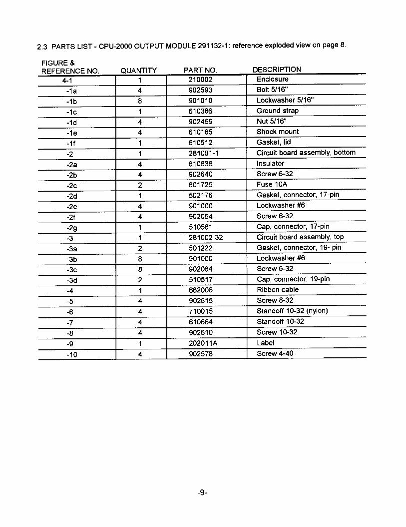
2.3 PARTS LIST - CPU-2000 OUTPUT MODULE 291132-1: reference exploded view on page 8.
FIGURE & REFERENCE NO.
4-1
-1a
-1b
-1c
-1d
-1e
-1f
-2
-2a
-2b
-2c
-2d
-2e
-2f
-2g
-3
-3a
-3b
-3c
-3d
-4
-5
-6
-7
-8
-9
-10
QUANTITY 1
4
8
1
4
4
1
1
4
4
2
1
4
4
1
1
2
8
8
2
1
4
4
4
4
1
4
PART NO. DESCRIPTION
210002 Enclosure
902593 Bolt 5/16"
901010 Lockwasher 5/16"
610386 Ground strap
902469 Nut 5/16"
610165 Shock mount
610512 Gasket, lid
281001-1 Circuit board assembly, bottom
610636 Insulator
902640 Screw 6-32
601725 Fuse 10A
502176 Gasket, connector, 17-pin
901000 Lockwasher #6
902064 Screw 6-32
510561 Cap, connector, 17-pin
281002-32 Circuit board assembly, top
501222 Gasket, connector, 19- pin
901000 Lockwasher #6
902064 Screw 6-32
510517 Cap, connector, 19-pin
662008 Ribbon cable
902615 Screw 8-32
710015 Standoff 10-32 (nylon)
610664 Standoff 10-32
902610 Screw 10-32
202011A Label
902578 Screw 4-40
-9-

2.3 PARTS LIST - CPU-2000 OUTPUT MODULE 291132-2: reference exploded view on page 8.
FIGURE & REFERENCE NO.
4-1
-1a
-1b
-1c
-1d
-1e
-1f
-2
-2a
-2b
-2c
-2d
-2e
-2f
-2g
-3
-3a
-3b
-3c
-3d
-4
-5
-6
-7
-8
-9
-10
QUANTITY
1
4
8
1
4
4
1
1
4
4
2
1
4
4
1
1
2
8
8
2
1
4
4
4
4
1
4
PART NO. DESCRIPTION
210002 Enclosure
902593 Bolt 5/16"
901010 Lockwasher 5/16"
610386 Ground strap
902469 Nut 5/16"
610165 Shock mount
610512 Gasket, lid
281001-2 Circuit board assembly, bottom
610636 Insulator
902640 Screw 6-32
601725 Fuse 10A
502176 Gasket, connector, 17-pin
901000 Lockwasher #6
902064 Screw 6-32
510561 Cap, connector, 17-pin
281002-32A Circuit board assembly, top
501222 Gasket, connector, 19- pin
901000 Lockwasher #6
902064 Screw 6-32
510517 Cap, connector, 19-pin
662008 Ribbon cable
902615 Screw 8-32
710015 Standoff 10-32 (nylon)
610664 Standoff 10-32
902610 Screw 10-32
202011A Label
902578 Screw 4-40
-10-

PARTS IDENTIFICATION
0
Figure 5
-11-
n ,
dtj II
II
II
II
II
II
II
II
II
II
II
II
II
II
II
II
II

2.4 PARTS LIST - CPU-2000 DIAGNOSTIC MODULE 291105-1: reference exploded view page 11.
FIGURE & REFERENCE NO
5-1
-1a
-1b
-1c
-1d
-1e
-2
-3
-4
-5
-6
-7
-8
-9
-10
-11
-12
-13
-14
-15
-16
QUANTITY
1
4
8
1
4
4
1
1
1
1
2
1
1
16
2
1
1
4
1
4
3
PART NO. DESCRIPTION
210004 Enclosure
902593 Bolt 5/16"
901010 Lockwasher 5/16"
610386 Ground strap
902469 Nut 5/16"
610165 Shock mount
610512 Gasket, lid
601668-A EEprom, blank
601868 Microprocessor
272010-1 Circuit board assembly
502176 Gasket, connector, 17-pin
501369 Gasket, connector, 3-pin
501372 Gasket, connector, 10-pin
902648 Screw 6-32 seal
510561 Cap, connector, 17 pin
510516 Cap, connector, 3-pin
604122 Cap, connector, 10-pin
902439 Screw 10-32
202022A Label
902651 Screw 4-40 seal
601653 Fuse 6.3A
-12-

3.0 TEST STAND REQUIREMENTS
3.1 In order to test an Altronic CPU-2000 ignition system, a special test stand is required. The basic test stand is similar to that required for the Altronic II-CPU system.
3.2 The following items are required to test the Altronic CPU-2000 system: A A variable speed motor of 0.5 HP or greater, capable of rotating 1500 RPM with a standard
ignition drive accepting either flange or base mounting. B. A spark degree wheel graduated in 360 increments with the indicator attached to the shaft
driving the Altronic II unit.C. Sixteen (16) 291001 ignition coils connected to suitable, adjustable spark gaps. NOTE: The test
stand should incorporate thirty-two (32) ignition coils if 32-output units are tested.D. A source of gear tooth pulses mechanically connected to the Altronic II unit drive; a 180-tooth
gear is recommended.E. A single reset pin (6-32 steel machine screw recommended) mounted to the face of the gear.F. Magnetic pickups (691118-x) mounted to sense the gear teeth (A) and the reset pin (B).G. A primary wiring harness connecting the ignition coils to the CPU-2000 Output Module. This
requires connector MS3108A-22-14S, Altronic part number 504056. NOTE: Two harnesses arerequired to test 32-output units.
H. A 581602 manual control loop unit to simulate the 4-20mA control signal.I. A DC power source capable of supplying 24Vdc, 10 amps - see Installation Instructions form
CPU-2000 II, section 10.4 and drawing 209 120.J. An Altronic II-CPU Alternator; part no. 290213H is recommended. A distributor shaft assembly
with 2: 1 gear installed is required to test a 4-cycle application. The rotating magnet on thedistributer shaft assembly must be over the Hall-effect switch when the reset pin on the teststand is opposite its magnetic pickup.
K. An Altronic II-CPU back cover assembly 281500-1 or -2 and mating harness 293024-1. Connectthe wiring harness as shown on the following page.
L. A blank CPU-2000 EEPROM, Altronic part number 601668-A. Test memories can be used ifthe Terminal Program is not used. Test memories for 16 and 32-cylinder, 4-cycle applicationsprogrammed with the number of teeth used on the test stand (usually 180) will be needed.
M. Altronic CPU-2000 Terminal Program part number CPU-2000.MEM.NOTE: Reference form CPU-2000 Pl, section 1.3 for computer and peripheral requirements forthe Terminal Program.
N. A means to elevate CPU-2000 Output Module to a controlled temperature of 150 ° F. (65° C.).0. A 293030-25 cable to connect the Logic Module to the Output Module.
NOTE: Altronic Test Unit 791025-1 can provide simulated pickup signals to exercise the CPU-2000 outputs at a fixed firing rate.
P. The optional CPU-2000 Diagnostic Module 291105-1 can be adapted using harness 293031 anda 3-conductor cable 593050 as shown in the Test Stand Wiring diagram.
-13-

MOTOR
18 0 TD O TH .,,.,,--rrn,,rnlt'__..: GEAR
SPARK:::;;;;::;==:;
\./HEEL
AL TRONIC II
CPU-2000 LOGIC MODULE CPU-2000 I
OUTPUT MODULE I
RESET PIN
581602 0 >---�
DODD □□□□ DODD □□□□
i I I I
GEAR TEETH I RESET I
I I
L ___ 7
OPTIONAL I DIAGNOSTIC I
MODULE I I I I I
I
I HALL-EFFECT L_
'------ - - -----�� ____ _._ ___ � L __ J
II CPU BACK COVER 281500-x 24 VDC
TEST STAND WIRING
4-CYCLE PICKUP INPUT WIRING
CPU-2000 LOGIC INPUT 281500-X 5-PIN CONNECTOR
A (4-cycle pickup) PIN E
B (4-cycle pickup) PIN D
C (4-cycle pickup) PIN C
PIN B
PINA
DESCRIPTION
HALL EFFECT OUTPUT
HALL EFFECT(+) SUPPLY
HALL EFFECT(-) RETURN
* SEE NOTE 1
* SEE NOTE 1
*Note 1: Connect leads A and B together (shorts the alternator output)
-14-

4.0 TESTING PROCEDURE -CPU-2000 OUTPUT MODULES 291116-1, 291132-1
4.1 VOLTAGE OUTPUT TEST - Connect the Output Module to a test Logic Module. Reference Installation Instructions form CPU-2000 II for correct wiring of the Logic Module. Set Logic Module for energy level 2 (E2). Operate the test stand at 360 RPM leaving the 19-pin connector(s) disconnected. Output voltage is measured from the "P" pin (+) to the "N" pin (-) and from the "P" pin (+) to the "V" pin (-) with an oscilloscope. The output voltage should be 320 ±10 Vdc for both measurements.
4.2 OPERATIONAL TEST - With the system completely connected, perform the following tests on the Output Module. It is recommended that these tests be performed with the CPU-2000 Output Module heated to a temperature of 150°F. (65°C.). Tests should be performed using a P4A180.HC memory for 16-output units and a P8A180.HC memory for 32-output models, assuming the test stand uses a 180 tooth gear.
180 TOOTH GEAR RPM TEST
75 RPM All outputs fire a 15mm gap.
360 RPM All outputs fire a 15mm gap.
360 RPM Each cylinder fires consistently in sequence: Timing as follows starting with output "A" and proceeding in alphabetical sequence:
Unit 291116-1: A-B-C-D-E-F-G-H-J-K-L-M-R-S-T-U
Unit 291132-1:
5.0 OHMMETER CHECKS
A 1-A2-B 1-B2-C1-C2-D1-D2-E 1-E2-F1-F2-G 1-G2-H 1-H2-J 1-J2-K 1-K2-L 1-L2-M 1-M2-R 1-R2-S 1-S2-T1-T2-U 1-U2 Note: X1 = upper connector; X2 = lower connector
5.1 CPU-2000 OUTPUT MODULE - The following tests should be made using a Simpson Model 260 analog volt-ohmmeter (VOM) set to "ohms". The ohmmeter scale should be set to "Rx 10,000". Readings outside the range indicated establish a defective Output Module. A unit passing the ohmmeter tests may still be defective and the full test should be performed using an oscilloscope (see sections 6.0) to confirm correct operation. A. Check the resistance with the negative lead of ohmmeter connected to the "N" lead and the
positive lead connected to each output pin of the output (top) connector. If ohmmeter readingis less than 250,000 ohms replace the Top Power Board (3-3, 4-3).
B. Check the resistance with the negative lead of ohmmeter connected to the "V" lead and thepositive lead connected to each output pin of the output (top) connector. If ohmmeter readingis less than 250,000 ohms replace the Top Power Board (3-3, 4-3).
C. Check the resistance with the positive lead of ohmmeter connected to the "P" lead and thenegative lead connected to each output pin of the output (top) connector. If ohmmeter readingis less than 250,000 ohms replace the Top Power Board (3-3, 4-3).
-15-

6.0 OSCILLOSCOPE TESTS
6.1 TEST SET-UP-Two 100:1 oscilloscope probes are required. Test speed is 360 RPM. NOTE: The signals being monitored are 290 to 350 volts, negative polarity. It is recommended that these tests be performed with the Output Module heated to a temperature of 150° F. (65° C.).
6.2 STORAGE CAPACITOR VOLTAGE PATTERN A. The trigger input of the oscilloscope should be connected to the "A" primary coil lead.
NOTE: This is a 290 to 350 volt, negative polarity signal.B. Connect the oscilloscope reading probe to the "N" lead of the output connector to view the "A"
side outputs. To view the "B" side outputs connect the oscilloscope probe to the "V" lead.Normal capacitor patterns are shown below.
C. Peak output voltage for the Output Module is:-290±10 volts for energy level E1,-320±10 volts for energy level E2,-350±10 volts for energy level E3.
6.3 MUL Tl-STRIKE TESTS A. Set the unit to MULTI-STRIKE mode via the keypad on the Logic Module.B. Connect oscilloscope to the "N" lead and view first set of shutdown pattern firings.C. Verify "A" firing is followed by three additional firings and the time between the first and fourth
firing is four to five milliseconds (See figure MUL Tl-STRIKE).D. Connect the oscilloscope probe to the "V" lead and repeat step C.
0 V.
100 V.
200 V
300 V.
350 V.
0 V
100 V
200 V
300 V
320 V
NORMAL PATlERN - N-LEAD
A C E G J L
MULTI-STRIKE • N-LEAD
1-- 45as -
0 V.
100 V.
200 V
300 V.
350 V.
0 V
100 V
200 V
300 V
320 V
NORMAL PAlTERN - V-LEAD
B D f H K M
MUL Tl-STRIKE - V-L[AD
1-- 45ss -
Shutdown Patterns
-16-

7.0 TESTING PROCEDURE - CPU-2000 LOGIC MODULE
7 .1 OPERATIONAL TESTS - Connect the Logic Module to a test Output Module known to be operational. Reference Installation Instructions form CPU-2000 II for correct wiring and Operating Instructions form CPU-2000 01 for operation of the Logic Module. Install a test EEPROM with the same number of teeth as the test stand and the same or less than the number of outputs on the test Output Module, or program a blank EEPROM. NOTE: Do not program over the original EEPROM. (A memory code P4A180.HC or a P8A180.HC is recommended for testing). Apply 24 Vdc input power to the unit and run at 360 RPM. Perform the following tests at room temperature. A Assure each output fires in sequence, with no multiple firings and in the correct timing on the
spark wheel: P4A180.HC firing pattern (in degrees): 0 -45 -90 -135 - 180 -225 - 270 - 315 - 0 - 45 - 90 -135 - 180 - 225 - 270 -315
P8A 180.HC firing pattern On degrees): 0 -22.5 -45 - 67.5 - 90 -112.5 - 135 -157.5 - 180 - 202.5-225 - 247.5 -270 -292.5 - 315-337.5-0 -22.5 - 45 - 67.5 -90-112.5-135-157.5-180-202.5-225-247.5-270-292.5-315-337.5
B. The display on the CPU-2000 Logic Module should read "FIRING".The panel 1/0 switches should be as follows:Fire Confirm Out - closed; Shutdown Out - closed; Alarm Out - closed.
C. Place Logic Module in Multi-Strike mode and assure outputs are multiple firing (ref. formCPU-2000 01 section 9.2 ). Turn Multi-Strike OFF before continuing the test.
D. Change the energy level from E1 to E3 and verify the output voltage changes from-290±10 volts to -350±10 volts (reference form CPU-2000 01, section 9.3).
E. Ground the Panel 1/0 Shutdown Input. Ignition firings should immediately cease and the displayshould read "SHUTDOWN". The panel 1/0 switches should be as follows:Fire Confirm Out - open; Shutdown Out - closed; Alarm Out - closed.
7.2 TIMING TESTS. - The following tests should be performed on the Logic Module to verify proper control of timing (reference form CPU-2000 01, sections 5.0-8.3). A Enter the TIMING menu and test the GLOBAL RETARD. Vary the global timing and verify the
timing changes on the spark wheel and on the display (reference form CPU-2000 01, section 5.0).
B. Enter the TIMING menu and test the ONE-STEP RETARD. Ground the miscellaneous input inthe Logic Module and assure the timing retards by the one-step retard value (reference CPU-2000 01, section 6.5).
C. Vary the 4 to 20 mA loop and assure the timing retards 24 degrees at 20 mA (or other valuecorresponding to the memory program used).
8.0 TESTING PROCEDURE - CPU- 2000 DIAGNOSTIC MODULE
8.1 OPERATIONAL TESTS - Connect the Diagnostic Module to the test Logic and Output Modules as shown in the Test Stand Wiring diagram. Reference Installation Instructions form CPU-2000 II for correct wiring and Operating Instructions form CPU-2000 01 for operation of the Diagnostic Module. Operate the ignition and ENABLE the Diagnostic Module via setup screen. NOTE: The display board EPROM 601707 and logic board MICROPROCESSOR 601747 must be ver2.0 or higher for Diagnostic Module operation. Set the DIAG COUNT FREQ to LO via setup screen. Set the power level to E3S. A Verify RXD and TXD LED's are flashing and RES LED is on solid in the Diagnostic Module. B. Short the secondaries of A 1, A2 (32-output) or A, B (16-output) coils on the spark rack. NOTE:
the coils should be 291001 Altronic coils and wired one per output. The INST values should be85 +/- 15 counts for each of the two coils.
-17-

9.0 TROUBLESHOOTING
Perform all tests at a test stand speed of 360 RPM with a 4-cycle test memory. The following tests assume an adequate 12-24 Vdc power source and properly installed magnetic and Hall-effect pickups.
9.1 POWER MODULE - The following tests are to be performed with a known good Logic Module.
PROBLEM TEST TEST INDICATION CORRECTIVE ACTION (Figs. 3,4)
No output Section 4.1 Low voltage * Replace bottom power board (2).
One output Section Missing discharge Replace top power board (3). does not fire 4.2/6.2 on stand or scope
Only one output Section Only one spark gap Replace top power board (3). fires or fires 4.2/6.2 is firing consistently
No Multi-Strike Section 6.3 Outputs do not Measure voltage at pin 10 of Vss of function have four firings, 4- the ribbon cable on top power board.
5 milliseconds apart If voltage is 5V. in Multi-Strike mode, replace top power board. If voltage is 4V. or less, replace bottom power board.
* Logic Module display will read LOW OUTPUT VOL TS ON A (or B) SIDE(reference section 10.6 of CPU-2000 01).
** Logic Module display will read PRIMARY FAULT (reference section 10.6 of CPU-2000 01).
9.2 LOGIC MODULE - The following tests are to be performed with a known good Output Module. The tests assume a fully functional test stand.
PROBLEM TEST TEST INDICATION
Timing varies Section 7.1 Timing other than as shown
No function Section Pressing keypad from keypad 7.1/7.2 has no effect
No timing Section 7.2 Timing does not change from change when 4-20 4-20 mA input mA input is varied
*** May indicate a defective display or logic board.
CORRECTIVE ACTION (see Fig. 2)
Replace logic board (9).
Assure keypad is plugged in to display board. Replace keypad (2). ***
Replace logic board (9).
9.3 LOGIC MODULE DIAGNOSTICS MESSAGES - If any of the following diagnostic messages appear when testing the Logic Module then replace the logic board. A. GT PICKUP FAULT MISSING PULSESB. RS PICKUP FAULT MISSING PULSESC. HE PICKUP FAULT MISSING // NO-SYNCD. RING-GEAR FAULT xxx TEETH READ where xxx is not equal to the number of teeth on the test
stand.E. BOTTOM BOARD µP CHECKSUM FAILEDF. CURRENT LOOP OUT OF RANGE
-18-
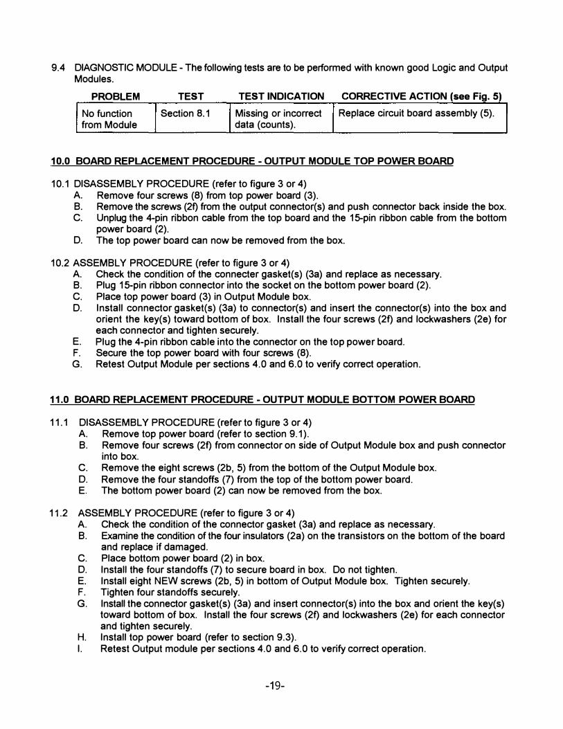
9.4 DIAGNOSTIC MODULE- The following tests are to be performed with known good Logic and Output Modules.
PROBLEM TEST TEST INDICATION CORRECTIVE ACTION (see Fig. 5)
No function Section 8.1 Missing or incorrect Replace circuit board assembly (5). from Module data (counts).
10.0 BOARD REPLACEMENT PROCEDURE -OUTPUT MODULE TOP POWER BOARD
10.1 DISASSEMBLY PROCEDURE (refer to figure 3 or 4) A. Remove four screws (8) from top power board (3).B. Remove the screws (2f) from the output connector(s) and push connector back inside the box.C. Unplug the 4-pin ribbon cable from the top board and the 15-pin ribbon cable from the bottom
power board (2).D. The top power board can now be removed from the box.
10.2 ASSEMBLY PROCEDURE (refer to figure 3 or 4) A. Check the condition of the connecter gasket(s) (3a) and replace as necessary.B. Plug 15-pin ribbon connector into the socket on the bottom power board (2).C. Place top power board (3) in Output Module box.D. Install connector gasket(s) (3a) to connector(s) and insert the connector(s) into the box and
orient the key(s) toward bottom of box. Install the four screws (2f) and lockwashers (2e) foreach connector and tighten securely.
E. Plug the 4-pin ribbon cable into the connector on the top power board.F. Secure the top power board with four screws (8).G. Retest Output Module per sections 4.0 and 6.0 to verify correct operation.
11.0 BOARD REPLACEMENT PROCEDURE-OUTPUT MODULE BOTTOM POWER BOARD
11.1 DISASSEMBLY PROCEDURE (refer to figure 3 or 4) A. Remove top power board (refer to section 9.1 ).B. Remove four screws (2f) from connector on side of Output Module box and push connector
into box.C. Remove the eight screws (2b, 5) from the bottom of the Output Module box.D. Remove the four standoffs (7) from the top of the bottom power board.E. The bottom power board (2) can now be removed from the box.
11.2 ASSEMBLY PROCEDURE (refer to figure 3 or 4) A. Check the condition of the connector gasket (3a) and replace as necessary.B. Examine the condition of the four insulators (2a) on the transistors on the bottom of the board
and replace if damaged.C. Place bottom power board (2) in box.D. Install the four standoffs (7) to secure board in box. Do not tighten.E. Install eight NEW screws (2b, 5) in bottom of Output Module box. Tighten securely.F. Tighten four standoffs securely.G. Install the connector gasket(s) (3a) and insert connector(s) into the box and orient the key(s)
toward bottom of box. Install the four screws (2f) and lockwashers (2e) for each connectorand tighten securely.
H. Install top power board (refer to section 9.3).I. Retest Output module per sections 4.0 and 6.0 to verify correct operation.
-19-

12.0 BOARD REPLACEMENT PROCEDURE-LOGIC MODULE DISPLAY BOARD
12.1 DISASSEMBLY PROCEDURE (refer to figure 2) A. Unplug keypad cable.B. Remove four screws (7) from the shield board (13) on the display board (12) and remove
shield board.C. Remove ribbon cable.D. Remove four standoffs (8) and remove display board (12).
12.2 ASSEMBLY PROCEDURE (refer to figure 2) A. Replace display board (12) and secure with four standoffs (8).B. Connect ribbon cable to display board.C. Replace shield board with notch (13) over the ribbon cable. Tighten 4 screws (7).D. Plug keypad cable into display board.E. Retest Logic module per section 7.0 to verify correct operation.
13.0 BOARD REPLACEMENT PROCEDURE-LOGIC MODULE LOGIC BOARD
13.1 DISASSEMBLY PROCEDURE (refer to figure 2) A. Remove four screws (7) and remove shield board (10).B. Remove two screws (7) and five standoffs (8) and remove the logic board (9).C. Disconnect ribbon cable from the logic board.
13.2 ASSEMBLY PROCEDURE (refer to figure 2) A. Connect ribbon cable to logic board (9).B. Put logic board in Logic Module box and secure with top screws (7) and five standoffs (8).C. Replace shield board (10) and secure with four screws (7).D. Retest Logic Module per section 7.0 to verify correct operation.
14.0 BOARD REPLACEMENT PROCEDURE -DIAGNOSTIC MODULE
14.1 DISASSEMBLY PROCEDURE (refer to figure 5) A. Remove sixteen screws (9) from four connectors and push connectors into box.B. Remove four screws (13) from circuit board.C. The circuit board assembly can now be removed from the enclosure.
14.2 ASSEMBLY PROCEDURE (refer to figure 5) A. Check the condition of the connector gaskets (6, 7, 8) and replace as necessary.B. Place circuit board assembly (5) in enclosure (1).C. Install and securely tighten four screws (13) to secure board in enclosure.D. Install connector gaskets and install connectors into enclosure with keys oriented toward the
bottom of the box.E. Install sixteen new screws (9) into connectors and tighten securely.F. Retest the Diagnostic Module per sections 4.0, 7.0 and 8.0 to verify correct operation.
-20-