Embed Size (px)
Citation preview

Buildings Energy Efficiency Bill
The Administration’s response to Action Items at the Bills Committee meeting on 11 March 2010
Definition of “industrial building”
The definition of “industrial building” under the Buildings Energy Efficiency Bill (the Bill), which reads –
“industrial building” means – (a) a building in which –
(i) articles are manufactured, altered, cleaned, repaired, ornamented, finished, adapted for sale, broken up or demolished; or
(ii) materials are transformed; or
(b) a godown,
is modeled on the definition of “industrial building” adopted in the Building (Refuse Storage and Material Recovery Chambers and Refuse Chutes) Regulations (Cap. 123H). Members of the Bills Committee enquired the reason for not adopting the definition used in the Land (Compulsory Sale for Redevelopment) (Specification of Lower Percentage) Notice, which reads –
“industrial building” means a building the whole or any part of which is approved by the Building Authority for any of the following uses under a plan approved under the Buildings Ordinance (Cap. 123) – (a) godown;
(b) any industry in which articles are manufactured, altered,
cleaned, repaired, ornamented, finished, adapted for sale, broken up or demolished, or in which materials are transformed.
2. As explained in LC Paper CB(1) 1378/09-10(01), the policy intention under the said Notice is not only to cover industrial buildings aged 30 years or above within a non-industrial zone that are still in use, but also to cover such industrial buildings which are under-utilised or have been left to disuse. As such, the definition of “industrial building”
CB(1) 1492/09-10(02)
- 2 -
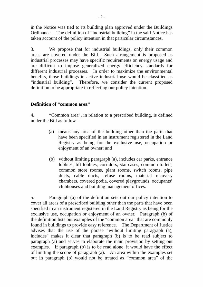
in the Notice was tied to its building plan approved under the Buildings Ordinance. The definition of “industrial building” in the said Notice has taken account of the policy intention in that particular circumstances. 3. We propose that for industrial buildings, only their common areas are covered under the Bill. Such arrangement is proposed as industrial processes may have specific requirements on energy usage and are difficult to impose generalized energy efficiency standards for different industrial processes. In order to maximize the environmental benefits, those buildings in active industrial use would be classified as “industrial building”. Therefore, we consider the current proposed definition to be appropriate in reflecting our policy intention. Definition of “common area” 4. “Common area”, in relation to a prescribed building, is defined under the Bill as follow –
(a) means any area of the building other than the parts that have been specified in an instrument registered in the Land Registry as being for the exclusive use, occupation or enjoyment of an owner; and
(b) without limiting paragraph (a), includes car parks, entrance
lobbies, lift lobbies, corridors, staircases, common toilets, common store rooms, plant rooms, switch rooms, pipe ducts, cable ducts, refuse rooms, material recovery chambers, covered podia, covered playgrounds, occupants’ clubhouses and building management offices.
5. Paragraph (a) of the definition sets out our policy intention to cover all areas of a prescribed building other than the parts that have been specified in an instrument registered in the Land Registry as being for the exclusive use, occupation or enjoyment of an owner. Paragraph (b) of the definition lists out examples of the “common area” that are commonly found in buildings to provide easy reference. The Department of Justice advises that the use of the phrase “without limiting paragraph (a), includes" makes it clear that paragraph (b) is to be read subject to paragraph (a) and serves to elaborate the main provision by setting out examples. If paragraph (b) is to be read alone, it would have the effect of limiting the scope of paragraph (a). An area within the examples set out in paragraph (b) would not be treated as “common area” of the

- 3 -
prescribed building if that area has been specified in an instrument registered in the Land Registry as being for the exclusive use, occupation or enjoyment of an owner. 6. The proposed definition is modeled on the definition of “common parts” adopted in the Building Management Ordinance (Cap. 344). Scope and application of clauses 8 to 13 7. Duties set out in clauses 8 to 13 of the Bill are applicable to prescribed buildings in respect of which their consent to the commencement of building works for superstructure construction is given after the commencement of Part 2 of the Bill. A schematic presentation on the scope and application of clauses 8 to 13 is at Annex A. Responsibilities under clause 12 of the Bill 8. Clause 12 of the Bill requires an owner of a building and a responsible person of a unit of a building to ensure that the central building services installations and other building services installations are maintained to a certain standard. The policy intent is to prevent the building services installations from being altered or replaced with less energy efficient components subsequently, and that the installations can be properly maintained to prevent undue decline in energy efficiency. 9. The specified standards set out in Building Energy Codes are standards and requirements on design parameters, rather than those on daily operational performance. In general, normal wear and tear of the installations should not have great impact on their energy efficiency performance when they are properly maintained. Owners and responsible persons may refer to equipment catalogue or in doubt, seek advice from qualified personnel in selecting proper replacement for the equipment and in conducting proper maintenance. The Electrical and Mechanical Services Department will prepare concise guidelines to facilitate compliance by owners and responsible persons. 10. Clause 12 of the Bill also requires the owner of a building must ensure that a Certificate of Compliance Registration (COCR) is in force in respect of the building. As stated in clause 10(4) that COCR is valid for 10 years, the policy intent of clause 12(1) is to ensure that COCR is

- 4 -
renewed in time. In light of the comments of the Bills Committee, we will revise clause 12(1) to set out clearly that only owners of buildings which have obtained COCR will have such responsibility. Periodic inspection, testing and certification of fixed electrical installations 11. Under Regulation 20 of the Electricity (Wiring) Regulations (Cap. 406E), an owner of a low voltage fixed electrical installation shall have the installation inspected, tested and certified at least once every five years. A similar requirement is imposed under the Bill for renewal of COCR (clause 13 of the Bill), which aims at certifying that the central building services installations in a prescribed building are maintained to a certain standard. Taking account of the service life of building services installations and the compliance burden on owners, we are of the view that the proposed 10-year renewal for COCR is appropriate. Samples of technical forms 12. Samples of technical forms (in English only) to be submitted as supplementary information for submissions of stage two declarations and Form of Compliance, as well as applications for renewal of COCR are at Annexes B to F respectively. We will prepare the Chinese version of the technical forms in due course. Environment Bureau Electrical and Mechanical Services Department March 2010
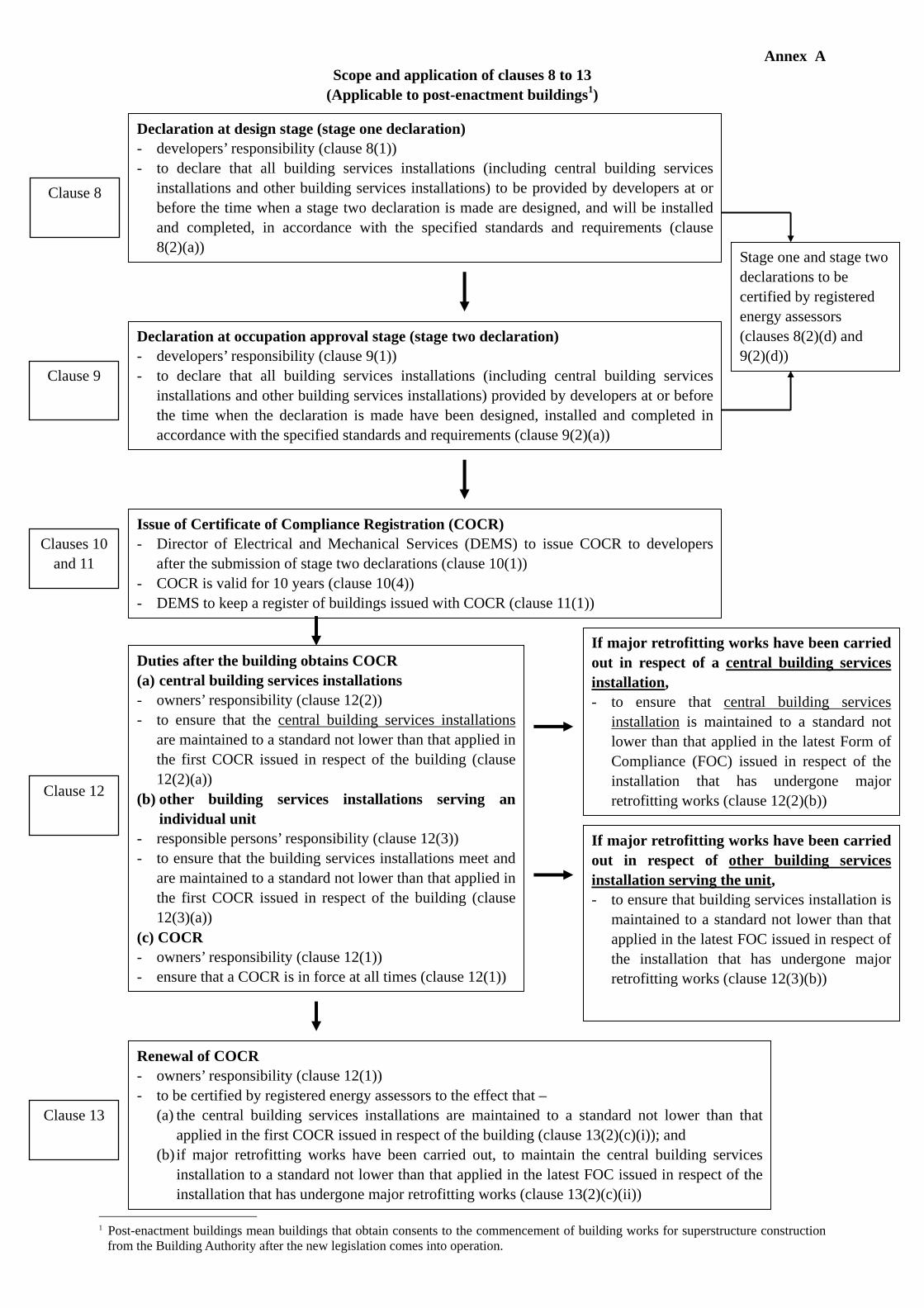
Annex A Scope and application of clauses 8 to 13
(Applicable to post-enactment buildings1)
1 Post-enactment buildings mean buildings that obtain consents to the commencement of building works for superstructure construction
from the Building Authority after the new legislation comes into operation.
Issue of Certificate of Compliance Registration (COCR) - Director of Electrical and Mechanical Services (DEMS) to issue COCR to developers
after the submission of stage two declarations (clause 10(1)) - COCR is valid for 10 years (clause 10(4)) - DEMS to keep a register of buildings issued with COCR (clause 11(1))
Clauses 10 and 11
Renewal of COCR - owners’ responsibility (clause 12(1)) - to be certified by registered energy assessors to the effect that –
(a) the central building services installations are maintained to a standard not lower than that applied in the first COCR issued in respect of the building (clause 13(2)(c)(i)); and
(b) if major retrofitting works have been carried out, to maintain the central building services installation to a standard not lower than that applied in the latest FOC issued in respect of the installation that has undergone major retrofitting works (clause 13(2)(c)(ii))
Clause 13
Declaration at design stage (stage one declaration) - developers’ responsibility (clause 8(1)) - to declare that all building services installations (including central building services
installations and other building services installations) to be provided by developers at or before the time when a stage two declaration is made are designed, and will be installed and completed, in accordance with the specified standards and requirements (clause 8(2)(a))
Declaration at occupation approval stage (stage two declaration) - developers’ responsibility (clause 9(1)) - to declare that all building services installations (including central building services
installations and other building services installations) provided by developers at or before the time when the declaration is made have been designed, installed and completed in accordance with the specified standards and requirements (clause 9(2)(a))
Clause 8
Clause 9
Stage one and stage two declarations to be certified by registered energy assessors (clauses 8(2)(d) and 9(2)(d))
Duties after the building obtains COCR (a) central building services installations - owners’ responsibility (clause 12(2)) - to ensure that the central building services installations
are maintained to a standard not lower than that applied in the first COCR issued in respect of the building (clause 12(2)(a))
(b) other building services installations serving an individual unit
- responsible persons’ responsibility (clause 12(3)) - to ensure that the building services installations meet and
are maintained to a standard not lower than that applied in the first COCR issued in respect of the building (clause 12(3)(a))
(c) COCR - owners’ responsibility (clause 12(1)) - ensure that a COCR is in force at all times (clause 12(1))
Clause 12
If major retrofitting works have been carried out in respect of a central building services installation, - to ensure that central building services
installation is maintained to a standard not lower than that applied in the latest Form of Compliance (FOC) issued in respect of the installation that has undergone major retrofitting works (clause 12(2)(b))
If major retrofitting works have been carried out in respect of other building services installation serving the unit, - to ensure that building services installation is
maintained to a standard not lower than that applied in the latest FOC issued in respect of the installation that has undergone major retrofitting works (clause 12(3)(b))

Annex B Technical Data of Lighting Installation Form EE-LG For substantiation of compliance with Section 5 of COP in Energy Efficiency of BS Installations in Buildings (BEC)
EMSD page 1 of 2 Energy Efficiency Office
Lighting Installations Summary Part 1
Name of Building :
Registered Energy Assessor :
Name: Registration No:
Submission Date: Signature:
Lighting Load Total area with fixed lighting installations (m2) :
Total Installed lighting power (kW) :
Submitted Forms, Drawings, Catalogues etc. (tick where applicable)
Submittal No. of Sheets□ Form EE-LG Part 1 (Lighting Installations Summary)
□ Form EE-LG Part 2 (Lighting Power Density Worksheet)
□ Drawings to show lighting layouts (for the luminaires contributing to the LPD in Part 2 of this form) in various lighting spaces
□ A drawing summary list to indicate the drawing title and number.
□ Technical brochures / catalogues (for the luminaires contributing to the LPD in Part 2 of this form), substantiating the circuit wattage of each luminaire
□ A brochures/catalogues summary list indicating their titles and corresponding luminaires
□ Others (to give details) _________________________________________________________
__________________________________________________________________________
Remarks:-
Total Installed Lighting Power refers to the sum of circuit wattage (i.e. lamp wattage plus lamp control gear loss) of all luminaries included in the calculation of lighting power density. (Calculation details should be properly filed for ready retrieval for inspection)
Lighting layouts should show :
for each space the positions of luminaires;
for each office space the no. of luminaires controlled by each lighting control point;
a summary of the different types of luminaires, with a brief description of each luminaire type, including
- circuit wattage,
- no. of lamps per luminaire, and
- type of lamp including T5 tubular fluorescent, T8 tubular fluorescent, compact fluorescent, metal halide, light emitting diode, high pressure sodium, tungsten halogen etc.

Annex B Technical Data of Lighting Installation Form EE-LG For substantiation of compliance with Section 5 of COP in Energy Efficiency of BS Installations in Buildings (BEC)
EMSD page 2 of 2 Energy Efficiency Office
Lighting Power Density Part 2
Designation Lighting Power Density (LPD) (W/m2)
Block
Floor Name of Space
Area (m2) Type of Space *1
General lighting *2
Decorative lighting *3
No. of control
points *4
for office
Remarks:- *1 To insert the type of space per categorization in Table 5.4 of the BEC. *2 Calculated LPD of general lighting that provides a substantially uniform level of illumination throughout and
maintained type emergency lighting. *3 Calculated LPD of general lighting included in the installations specified in clause 6(a) of Schedule 2 of the
Ordinance (solely used for Decoration / Visual Production / Illumination of an Exhibit or Product on Display). *4 Figure to be inserted only for a space classified as an office. *2 *3 The LPD for General lighting has to comply with the corresponding requirement in Table 5.4 of this BEC.
LPD for display lighting, decorative lighting and visual production lighting are to be provided to EMSD for information only.
Please insert more rows where applicable, for all the relevant spaces in the building.

Annex C Technical Data of Air Conditioning Installation Form EE-AC For substantiation of compliance with Section 6 of COP in Energy Efficiency of BS Installations in Buildings (BEC)
EMSD page 1 of 10 Energy Efficiency Office
AC Installations Summary
Part 1
Name of Building :
Registered Energy Assessor :
Name: Registration No:
Submission Date: Signature:
AC Load
Conditioned Area (m2)
Calculated Block Cooling Load (kW) Installed Total Plant Capacity (kW)
Calculation Method : □ ASHRAE □ CIBSE □ Others (Please specify)
(tick where applicable) Note : Calculation details should be properly filed for ready retrieval.
Submitted AC Forms, Drawings, Catalogues etc. (tick where applicable)
Submittal No. of Sheets
□ Form EE-AC Part 1 (AC Installation Summary)
□ Form EE-AC Part 2 (Design Parameters Worksheet)
□ Form EE-AC Part 3 (AC Systems and Controls Worksheet)
□ Form EE-AC Part 4 (Air Duct Leakage Test Worksheet)
□ Form EE-AC Part 5 (AC Equipment Efficiency Worksheet)
□ Form EE-AC Part 6 (Fan Motor Power Worksheet)
□ Drawings to show the water-side and air-side distribution schematics
□ A drawings summary list to indicate the drawing titles and number.
□ Technical brochures / catalogues (for power rating and efficiency of the equipments submitted in the Form)
□ A brochures / catalogues summary list to indicates the type of equipment.
□ Others (to give details)
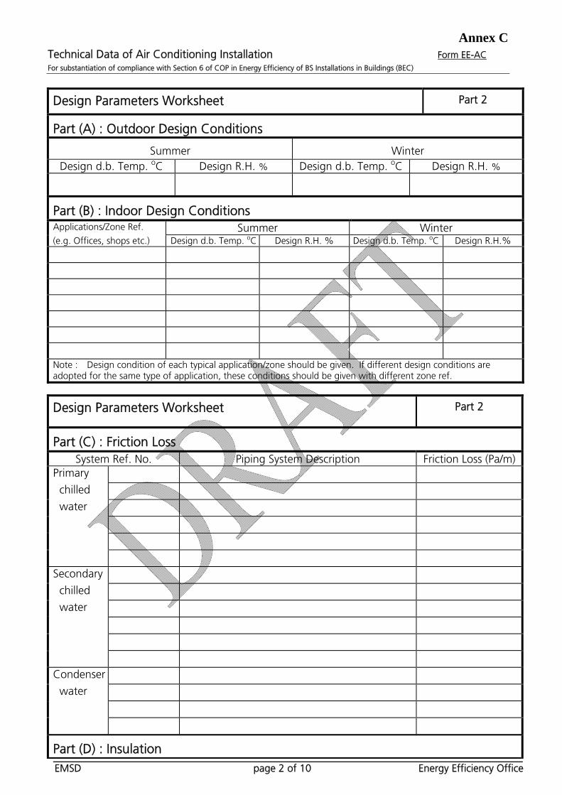
Annex C Technical Data of Air Conditioning Installation Form EE-AC For substantiation of compliance with Section 6 of COP in Energy Efficiency of BS Installations in Buildings (BEC)
EMSD page 2 of 10 Energy Efficiency Office
Design Parameters Worksheet
Part 2
Part (A) : Outdoor Design Conditions
Summer Winter Design d.b. Temp. oC Design R.H. % Design d.b. Temp. oC Design R.H. %
Part (B) : Indoor Design Conditions Applications/Zone Ref. Summer Winter (e.g. Offices, shops etc.) Design d.b. Temp. oC Design R.H. % Design d.b. Temp. oC Design R.H.%
Note : Design condition of each typical application/zone should be given. If different design conditions are adopted for the same type of application, these conditions should be given with different zone ref.
Design Parameters Worksheet
Part 2
Part (C) : Friction Loss System Ref. No. Piping System Description Friction Loss (Pa/m)
Primary
chilled
water
Secondary
chilled
water
Condenser
water
Part (D) : Insulation
Annex C Technical Data of Air Conditioning Installation Form EE-AC For substantiation of compliance with Section 6 of COP in Energy Efficiency of BS Installations in Buildings (BEC)
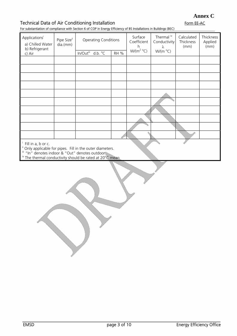
EMSD page 3 of 10 Energy Efficiency Office
Operating Conditions
Applicationsi
a) Chilled Water b) Refrigerant c) Air
Pipe Sizeii
dia.(mm)
In/Outiii d.b. oC RH %
Surface Coefficient
h W/(m2 oC)
Thermal iv Conductivity
W/(m oC)
Calculated Thickness
(mm)
Thickness Applied(mm)
i Fill in a, b or c. ii Only applicable for pipes. Fill in the outer diameters. iii “In” denotes indoor & “Out” denotes outdoor. iv The thermal conductivity should be rated at 20oC mean
Annex C Technical Data of Air Conditioning Installation Form EE-AC For substantiation of compliance with Section 6 of COP in Energy Efficiency of BS Installations in Buildings (BEC)
EMSD page 4 of 10 Energy Efficiency Office
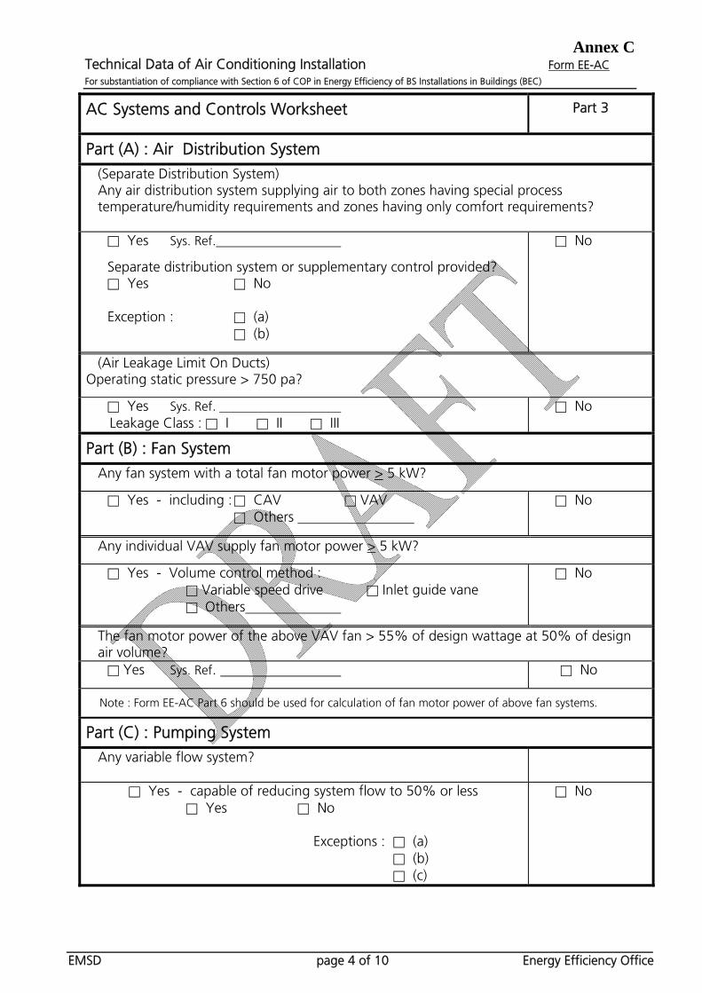
AC Systems and Controls Worksheet
Part 3
Part (A) : Air Distribution System
(Separate Distribution System) Any air distribution system supplying air to both zones having special process temperature/humidity requirements and zones having only comfort requirements?
□ Yes Sys. Ref. Separate distribution system or supplementary control provided? □ Yes □ No Exception : □ (a) □ (b)
□ No
(Air Leakage Limit On Ducts) Operating static pressure > 750 pa?
□ Yes Sys. Ref. Leakage Class : □ I □ II □ III
□ No
Part (B) : Fan System
Any fan system with a total fan motor power > 5 kW?
□ Yes - including : □ CAV □ VAV □ Others
□ No
Any individual VAV supply fan motor power > 5 kW?
□ Yes - Volume control method : □ Variable speed drive □ Inlet guide vane □ Others
□ No
The fan motor power of the above VAV fan > 55% of design wattage at 50% of design air volume?
□ Yes Sys. Ref. □ No
Note : Form EE-AC Part 6 should be used for calculation of fan motor power of above fan systems.
Part (C) : Pumping System Any variable flow system?
□ Yes - capable of reducing system flow to 50% or less □ Yes □ No
Exceptions : □ (a)
□ (b) □ (c)
□ No
Annex C Technical Data of Air Conditioning Installation Form EE-AC For substantiation of compliance with Section 6 of COP in Energy Efficiency of BS Installations in Buildings (BEC)
EMSD page 5 of 10 Energy Efficiency Office
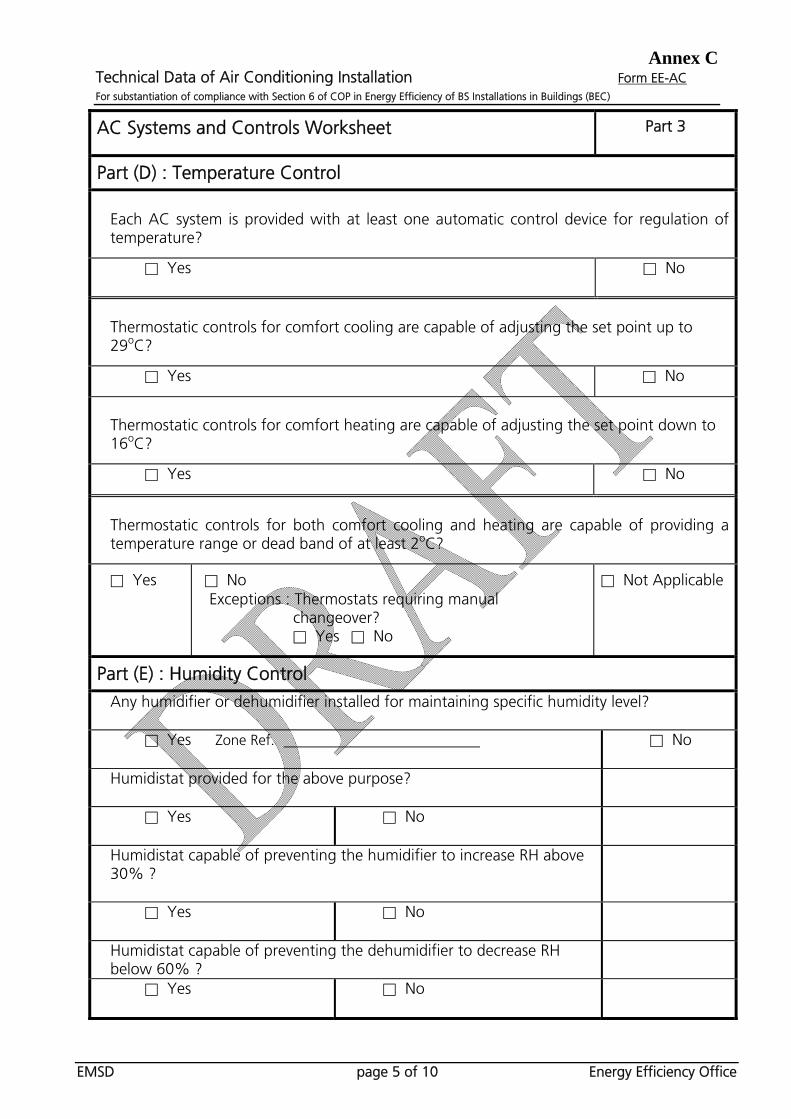
AC Systems and Controls Worksheet
Part 3
Part (D) : Temperature Control
Each AC system is provided with at least one automatic control device for regulation of temperature?
□ Yes □ No
Thermostatic controls for comfort cooling are capable of adjusting the set point up to 29oC?
□ Yes □ No
Thermostatic controls for comfort heating are capable of adjusting the set point down to 16oC?
□ Yes □ No
Thermostatic controls for both comfort cooling and heating are capable of providing a temperature range or dead band of at least 2oC?
□ Yes
□ No Exceptions : Thermostats requiring manual
changeover? □ Yes □ No
□ Not Applicable
Part (E) : Humidity Control
Any humidifier or dehumidifier installed for maintaining specific humidity level?
□ Yes Zone Ref. □ No
Humidistat provided for the above purpose?
□ Yes □ No
Humidistat capable of preventing the humidifier to increase RH above 30% ?
□ Yes □ No
Humidistat capable of preventing the dehumidifier to decrease RH below 60% ?
□ Yes □ No
Annex C Technical Data of Air Conditioning Installation Form EE-AC For substantiation of compliance with Section 6 of COP in Energy Efficiency of BS Installations in Buildings (BEC)
EMSD page 6 of 10 Energy Efficiency Office
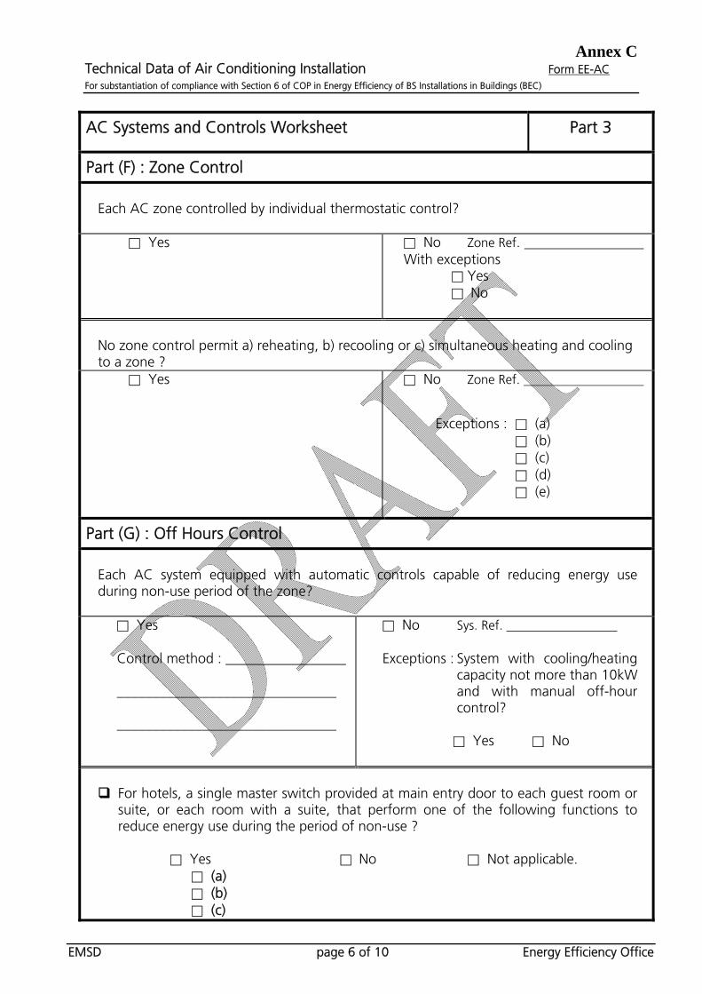
AC Systems and Controls Worksheet
Part 3
Part (F) : Zone Control
Each AC zone controlled by individual thermostatic control?
□ Yes □ No Zone Ref.
With exceptions □ Yes
□ No
No zone control permit a) reheating, b) recooling or c) simultaneous heating and cooling to a zone ?
□ Yes □ No Zone Ref.
Exceptions : □ (a)
□ (b) □ (c) □ (d) □ (e)
Part (G) : Off Hours Control
Each AC system equipped with automatic controls capable of reducing energy use during non-use period of the zone?
□ Yes Control method : _________________ _______________________________ _______________________________
□ No Sys. Ref. Exceptions : System with cooling/heating
capacity not more than 10kW and with manual off-hour control?
□ Yes □ No
For hotels, a single master switch provided at main entry door to each guest room or
suite, or each room with a suite, that perform one of the following functions to reduce energy use during the period of non-use ?
□ Yes □ No □ Not applicable. □ (a) □ (b) □ (c)

Annex C Technical Data of Air Conditioning Installation Form EE-AC For substantiation of compliance with Section 6 of COP in Energy Efficiency of BS Installations in Buildings (BEC)
EMSD page 7 of 10 Energy Efficiency Office
Air Duct Leakage Test Worksheet
Part 4
Test Section :
Drawing No. :
Total Surface Area of Tested Ducts Width and depth or diameter (mm)
Periphery (mm)
Length (m)
Area (m2)
Total
Design Data
Total duct surface area (m2)
Total surface area under test (m2) [From above table]
Duct operating static pressure - p (Pa)
Air leakage class
Air leakage limit (L/s per m2)
Maximum permitted leakage (L/s)
Test Records Summary
Date of test
Duct static pressure reading (Pa)
Duration of test (min) [Not less than 10 minutes]

Annex C Technical Data of Air Conditioning Installation Form EE-AC For substantiation of compliance with Section 6 of COP in Energy Efficiency of BS Installations in Buildings (BEC)
EMSD page 8 of 10 Energy Efficiency Office
AC Equipment Efficiency Worksheet
Part 5
Equipment Efficiency
Rated PLV (to be provided for equipment above
10kW)
Equipment. Ref. No.
Unit Type
Quantity
(No.)
Rated
Capacity(kW)
Total Rated
Capacity
(kW)
Rated COP at 100% load
Required COP (for
office use)
75% load
50% load
25% load
Rating Standard of COP & PLV (to state
standard (such as ARI), or other standards with
details *)
Accredited Body (such
as ARI)
Total * details to include as appropriate: condenser water entering temperature, water flow rate &
fouling factor, condenser entering air conditions, evaporator water leaving temperature, flow rate & fouling factor, refrigerant saturated discharge temperature & liquid temperature etc.
Annex C Technical Data of Air Conditioning Installation Form EE-AC For substantiation of compliance with Section 6 of COP in Energy Efficiency of BS Installations in Buildings (BEC)
EMSD page 9 of 10 Energy Efficiency Office
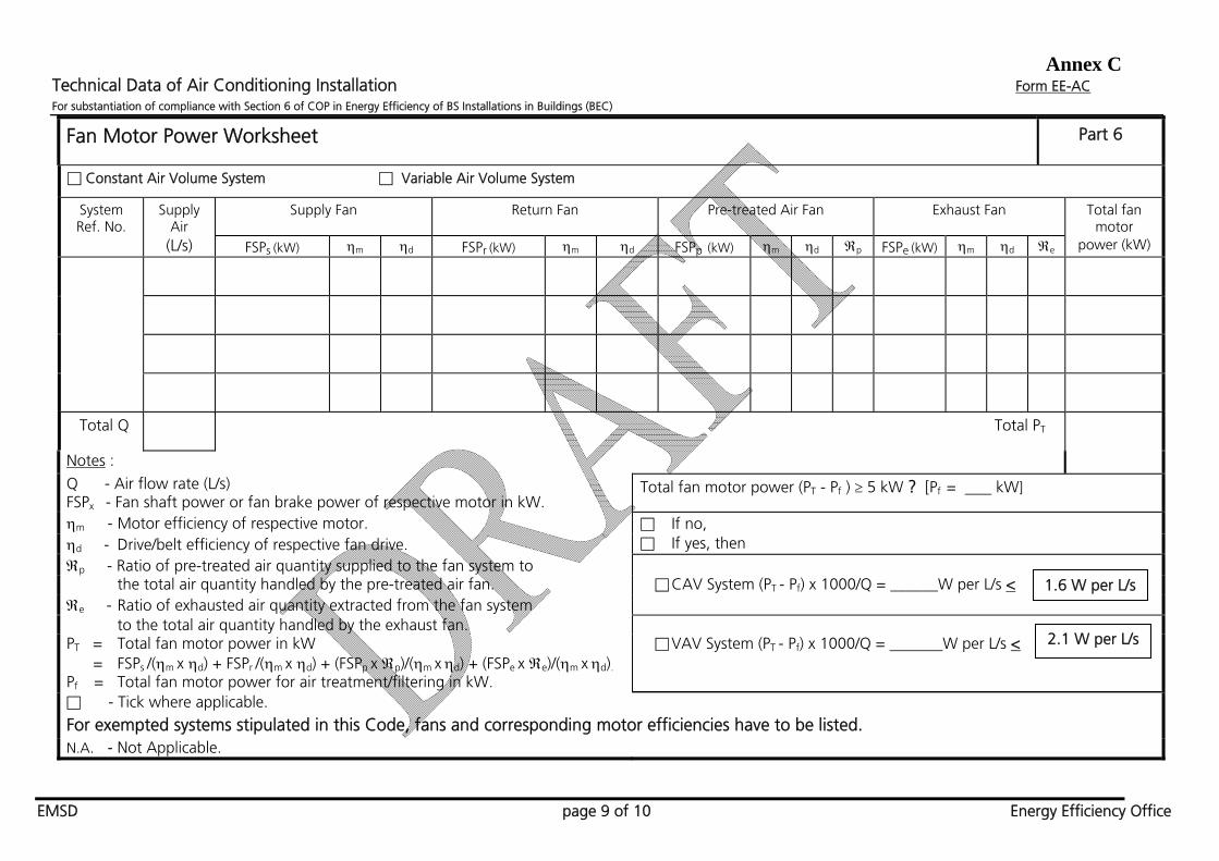
Fan Motor Power Worksheet
Part 6
□ Constant Air Volume System □ Variable Air Volume System
System Ref. No.
Supply Air
Supply Fan Return Fan Pre-treated Air Fan Exhaust Fan Total fan motor
(L/s) FSPs (kW) m d FSPr (kW) m d FSPp (kW) m d p FSPe (kW) m d e power (kW)
Total Q Total PT
Notes :
Q - Air flow rate (L/s) FSPx - Fan shaft power or fan brake power of respective motor in kW.
Total fan motor power (PT - Pf ) 5 kW ? [Pf = kW]
m - Motor efficiency of respective motor. □ If no, d - Drive/belt efficiency of respective fan drive. □ If yes, then p - Ratio of pre-treated air quantity supplied to the fan system to
the total air quantity handled by the pre-treated air fan. □ CAV System (PT - Pf) x 1000/Q = ______W per L/s < e - Ratio of exhausted air quantity extracted from the fan system
to the total air quantity handled by the exhaust fan. PT = Total fan motor power in kW = FSPs /(m x d) + FSPr /(m x d) + (FSPp x p)/(m x d) + (FSPe x e)/(m x d).
□ VAV System (PT - Pf) x 1000/Q = W per L/s <
Pf = Total fan motor power for air treatment/filtering in kW.
□ - Tick where applicable.
For exempted systems stipulated in this Code, fans and corresponding motor efficiencies have to be listed. N.A. - Not Applicable.
2.1 W per L/s
1.6 W per L/s

Annex C Technical Data of Air Conditioning Installation Form EE-AC For substantiation of compliance with Section 6 of COP in Energy Efficiency of BS Installations in Buildings (BEC)
EMSD page 10 of 10 Energy Efficiency Office
Fan Motor Power Worksheet
Part 6
System Ref. No.:
Air Flow Rate V (m3/s)
Clean Air Pressure Drop Pd (Pa)
Supply Fan Fan Efficiency f
Filtering Sys. Motor Efficiency m
Drive/Belt Efficiency d
Additional Motor Power Pf (kW)
Air Flow Rate V (m3/s)
Clean Air Pressure Drop Pd (Pa)
Return Fan Fan Efficiency f
Filtering Sys. Motor Efficiency m
Drive/Belt Efficiency d
Additional Motor Power Pf (kW)
Air Flow Rate V (m3/s)
Clean Air Pressure Drop Pd (Pa)
Fan Efficiency f
Pre-treated Air Motor Efficiency m
Fan Filtering Sys. Drive/Belt Efficiency d
Ratio of pre-treated air quantity supplied to the system to the total air quantity handled
by the pre-treated air fan
p
Additional Motor Power Pf (kW)
Air Flow Rate V (m3/s)
Clean Air Pressure Drop Pd (Pa)
Fan Efficiency f
Exhaust Fan Motor Efficiency m
Filtering Sys. Drive/Belt Efficiency d
Ratio of exhausted air quantity from the system to the total air quantity handled by
the exhaust fan
e
Additional Motor Power Pf (kW)
Total Pf (kW)
Notes: Pf = V x (Pd - 250)/( f x m x d). For pre-treated air fan and exhaust fan filtering systems, multiply
p & e respectively. Total Pf = Sum of the additional motor power of all filtering systems.
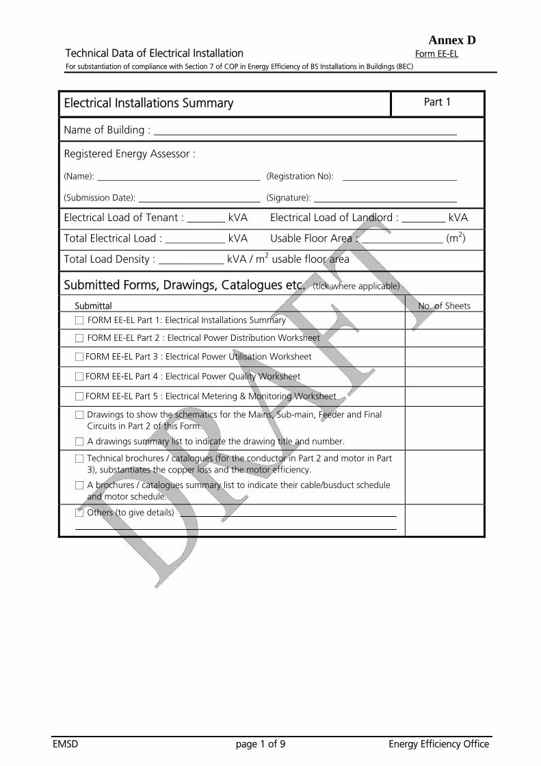
Annex D Technical Data of Electrical Installation Form EE-EL For substantiation of compliance with Section 7 of COP in Energy Efficiency of BS Installations in Buildings (BEC)
EMSD page 1 of 9 Energy Efficiency Office
Electrical Installations Summary Part 1
Name of Building :
Registered Energy Assessor :
(Name): (Registration No):
(Submission Date): (Signature):
Electrical Load of Tenant : _______ kVA Electrical Load of Landlord : ________ kVA
Total Electrical Load : ___________ kVA Usable Floor Area : _______________ (m2)
Total Load Density : ____________ kVA / m2 usable floor area
Submitted Forms, Drawings, Catalogues etc. (tick where applicable)
Submittal No. of Sheets
□ FORM EE-EL Part 1: Electrical Installations Summary
□ FORM EE-EL Part 2 : Electrical Power Distribution Worksheet
□ FORM EE-EL Part 3 : Electrical Power Utilisation Worksheet
□ FORM EE-EL Part 4 : Electrical Power Quality Worksheet
□ FORM EE-EL Part 5 : Electrical Metering & Monitoring Worksheet
□ Drawings to show the schematics for the Mains, Sub-main, Feeder and Final Circuits in Part 2 of this Form.
□ A drawings summary list to indicate the drawing title and number.
□ Technical brochures / catalogues (for the conductor in Part 2 and motor in Part 3), substantiates the copper loss and the motor efficiency.
□ A brochures / catalogues summary list to indicate their cable/busduct schedule and motor schedule.
□ Others (to give details)
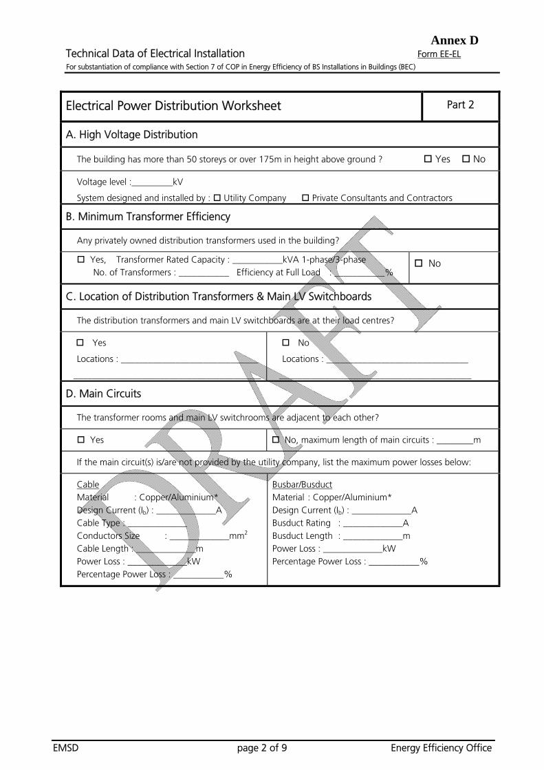
Annex D Technical Data of Electrical Installation Form EE-EL For substantiation of compliance with Section 7 of COP in Energy Efficiency of BS Installations in Buildings (BEC)
EMSD page 2 of 9 Energy Efficiency Office
Electrical Power Distribution Worksheet Part 2
A. High Voltage Distribution
The building has more than 50 storeys or over 175m in height above ground ? Yes No
Voltage level :_________kV
System designed and installed by : Utility Company Private Consultants and Contractors
B. Minimum Transformer Efficiency
Any privately owned distribution transformers used in the building?
Yes, Transformer Rated Capacity : ___________kVA 1-phase/3-phase No. of Transformers : ___________ Efficiency at Full Load : ___________%
No
C. Location of Distribution Transformers & Main LV Switchboards
The distribution transformers and main LV switchboards are at their load centres?
Yes
Locations : ______________________________
_________________________________________
No
Locations : _______________________________
__________________________________________
D. Main Circuits
The transformer rooms and main LV switchrooms are adjacent to each other?
Yes No, maximum length of main circuits : ________m
If the main circuit(s) is/are not provided by the utility company, list the maximum power losses below:
Cable Material : Copper/Aluminium* Design Current (Ib) : _____________A Cable Type : _____________ Conductors Size : _____________mm2 Cable Length : _____________m Power Loss : _____________kW Percentage Power Loss : ___________%
Busbar/Busduct Material : Copper/Aluminium* Design Current (Ib) : _____________A Busduct Rating : _____________A Busduct Length : _____________m Power Loss : _____________kW Percentage Power Loss : ___________%
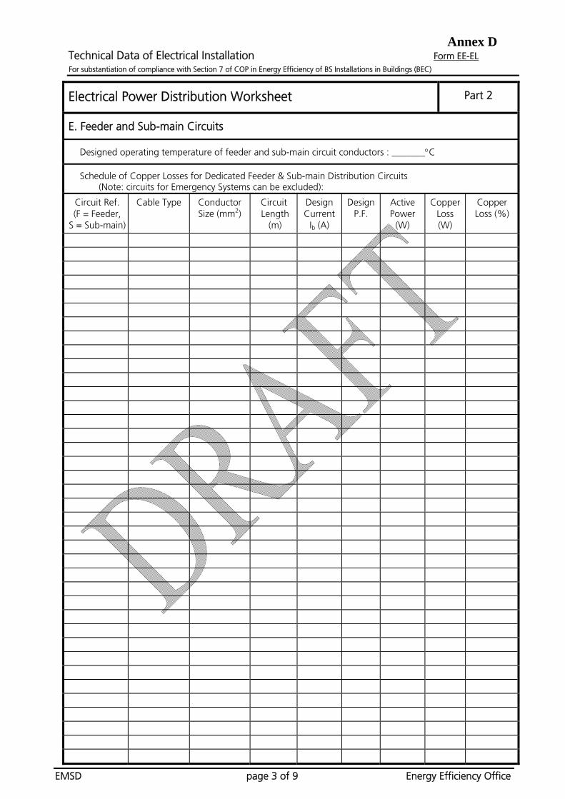
Annex D Technical Data of Electrical Installation Form EE-EL For substantiation of compliance with Section 7 of COP in Energy Efficiency of BS Installations in Buildings (BEC)
EMSD page 3 of 9 Energy Efficiency Office
Electrical Power Distribution Worksheet Part 2
E. Feeder and Sub-main Circuits
Designed operating temperature of feeder and sub-main circuit conductors : _______C
Schedule of Copper Losses for Dedicated Feeder & Sub-main Distribution Circuits (Note: circuits for Emergency Systems can be excluded):
Circuit Ref. (F = Feeder,
S = Sub-main)
Cable Type Conductor Size (mm2)
Circuit Length
(m)
Design Current
Ib (A)
Design P.F.
Active Power
(W)
Copper Loss (W)
Copper Loss (%)
Annex D Technical Data of Electrical Installation Form EE-EL For substantiation of compliance with Section 7 of COP in Energy Efficiency of BS Installations in Buildings (BEC)
EMSD page 4 of 9 Energy Efficiency Office
Electrical Power Distribution Worksheet Part 2
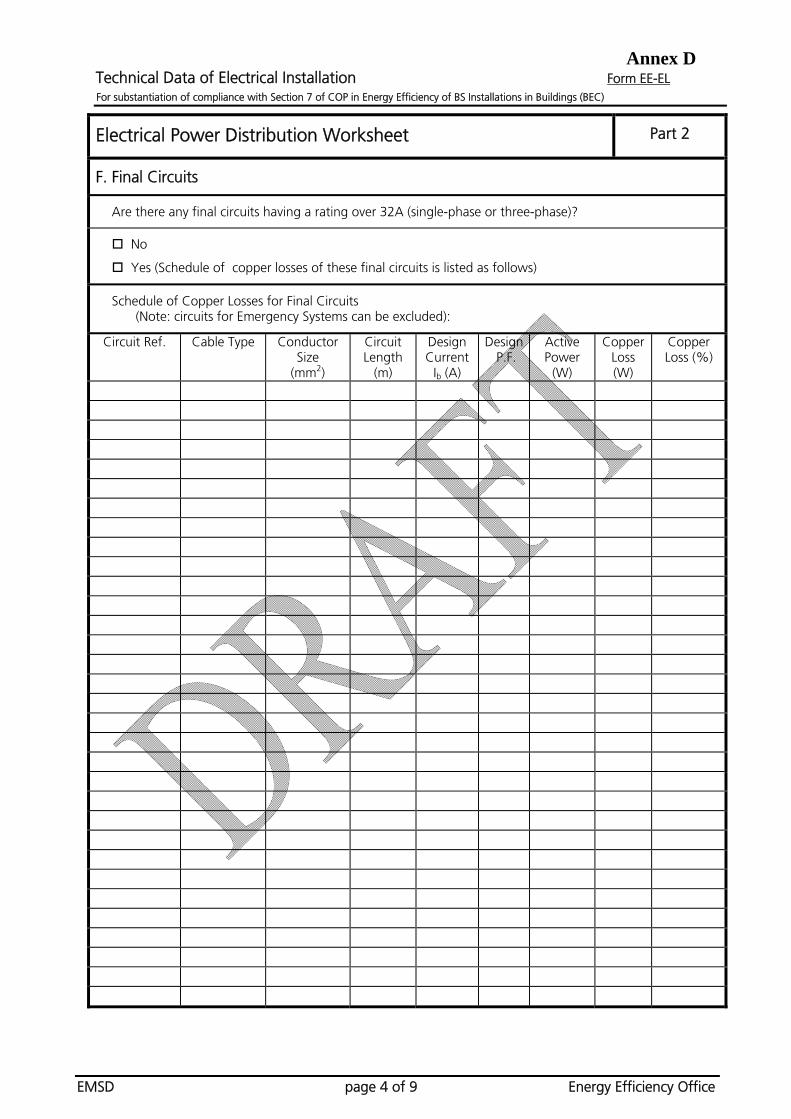
F. Final Circuits
Are there any final circuits having a rating over 32A (single-phase or three-phase)?
No
Yes (Schedule of copper losses of these final circuits is listed as follows)
Schedule of Copper Losses for Final Circuits (Note: circuits for Emergency Systems can be excluded):
Circuit Ref. Cable Type Conductor Size
(mm2)
Circuit Length
(m)
Design Current
Ib (A)
Design P.F.
Active Power
(W)
Copper Loss (W)
Copper Loss (%)
Annex D Technical Data of Electrical Installation Form EE-EL For substantiation of compliance with Section 7 of COP in Energy Efficiency of BS Installations in Buildings (BEC)
EMSD page 5 of 9 Energy Efficiency Office
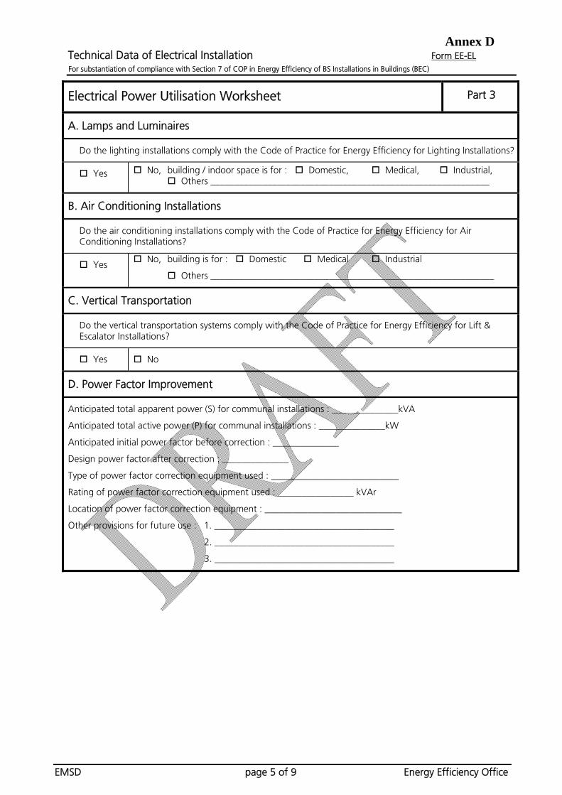
Electrical Power Utilisation Worksheet Part 3
A. Lamps and Luminaires
Do the lighting installations comply with the Code of Practice for Energy Efficiency for Lighting Installations?
Yes No, building / indoor space is for : Domestic, Medical, Industrial, Others ___________________________________________________________
B. Air Conditioning Installations
Do the air conditioning installations comply with the Code of Practice for Energy Efficiency for Air Conditioning Installations?
Yes No, building is for : Domestic Medical Industrial
Others ____________________________________________________________
C. Vertical Transportation
Do the vertical transportation systems comply with the Code of Practice for Energy Efficiency for Lift & Escalator Installations?
Yes No
D. Power Factor Improvement
Anticipated total apparent power (S) for communal installations : ______________kVA
Anticipated total active power (P) for communal installations : ______________kW
Anticipated initial power factor before correction : ______________
Design power factor after correction : ______________
Type of power factor correction equipment used : ___________________________
Rating of power factor correction equipment used : ________________ kVAr
Location of power factor correction equipment : _____________________________
Other provisions for future use : 1. ______________________________________
2. ______________________________________
3. ______________________________________

Annex D Technical Data of Electrical Installation Form EE-EL For substantiation of compliance with Section 7 of COP in Energy Efficiency of BS Installations in Buildings (BEC)
EMSD page 6 of 9 Energy Efficiency Office
Electrical Power Utilisation Worksheet Part 3
E. Motors and Drives
Are there any motors or driving systems having an output rating of 5kW or greater?
No
Yes, schedule of motors is listed as follows:
Motor Reference
Anticipated System
Load (kW)
Motor Rating (kW)
Full Load Motor
Efficiency (%)
Percentage Motor Rating to System Load (%)
VSD Type & Rating
Type of Power Transfer Devices
No. of Identical Motors
Annex D Technical Data of Electrical Installation Form EE-EL For substantiation of compliance with Section 7 of COP in Energy Efficiency of BS Installations in Buildings (BEC)
EMSD page 7 of 9 Energy Efficiency Office
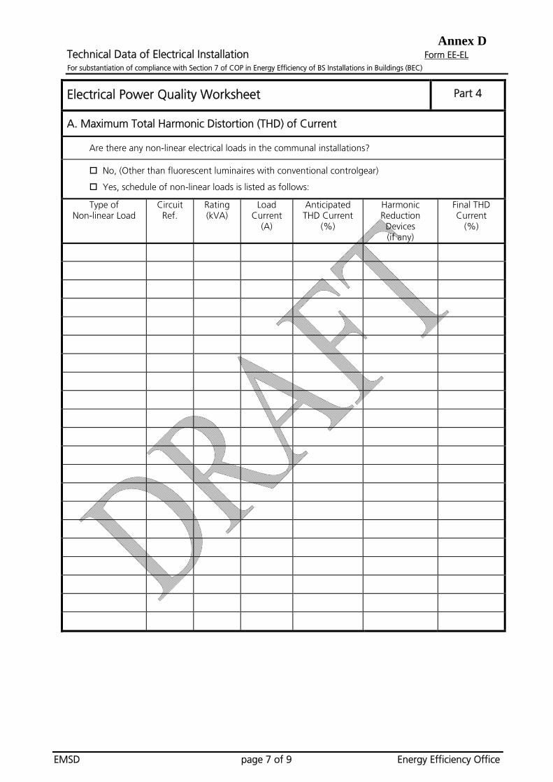
Electrical Power Quality Worksheet Part 4
A. Maximum Total Harmonic Distortion (THD) of Current
Are there any non-linear electrical loads in the communal installations?
No, (Other than fluorescent luminaires with conventional controlgear)
Yes, schedule of non-linear loads is listed as follows:
Type of Non-linear Load
Circuit Ref.
Rating (kVA)
Load Current
(A)
Anticipated THD Current
(%)
Harmonic Reduction Devices (if any)
Final THD Current
(%)

Annex D Technical Data of Electrical Installation Form EE-EL For substantiation of compliance with Section 7 of COP in Energy Efficiency of BS Installations in Buildings (BEC)
EMSD page 8 of 9 Energy Efficiency Office
Electrical Power Quality Worksheet Part 4
B. Balancing of Single-phase Loads
Are there any single-phase electrical loads (communal installations) connected in the three-phase four-wire power distribution system?
No Yes, schedule of load currents in each phase is listed as follows:
Sub-main Circuit Ref.
(with 1-phase loads)
Design Current in
Red Phase IR (A)
Design Current in
Yellow Phase IY (A)
Design Current in
Blue Phase IB (A)
Average Current Ia
(A)
Max. Deviation from Average
Id (A)
% Current Unbalance
Iu= (Id x100) Ia(%)

Annex D Technical Data of Electrical Installation Form EE-EL For substantiation of compliance with Section 7 of COP in Energy Efficiency of BS Installations in Buildings (BEC)
EMSD page 9 of 9 Energy Efficiency Office
Electrical Metering and Monitoring Worksheet Part 5
A. Main Circuits
Does the rating of any main incoming circuit exceed 400A, three-phase?
Yes
Ammeter to read: Red Phase Current (IR)
Yellow Phase Current (IY)
Blue Phase Current (IB)
Neutral Current (IN)
Voltmeter to read: Red to Yellow Line Voltage (VRY)
Yellow to Blue Line Voltage (VYB)
Blue to Red Line Voltage (VBR)
Red Phase to Neutral Voltage (VRN)
Yellow Phase to Neutral Voltage (VYN)
Blue Phase to Neutral Voltage (VBN)
Power Factor Meter
kWh Energy Meter
Maximum Demand Meter (kVA)
Other metering provisions/facilities : ______________________________________________ ______________________________________________ ______________________________________________ ______________________________________________
No
B. Sub-main and Feeder Circuits
Does the rating of any sub-main/feeder circuit exceed 200A, three-phase?
Yes Ammeter to read : Red Phase Current (IR)
Yellow Phase Current (IY) Blue Phase Current (IB) Neutral Current (IN)
kWh Energy Meter Other metering provisions/facilities : ______________________________________________ _____________________________________________ _____________________________________________ _____________________________________________
No
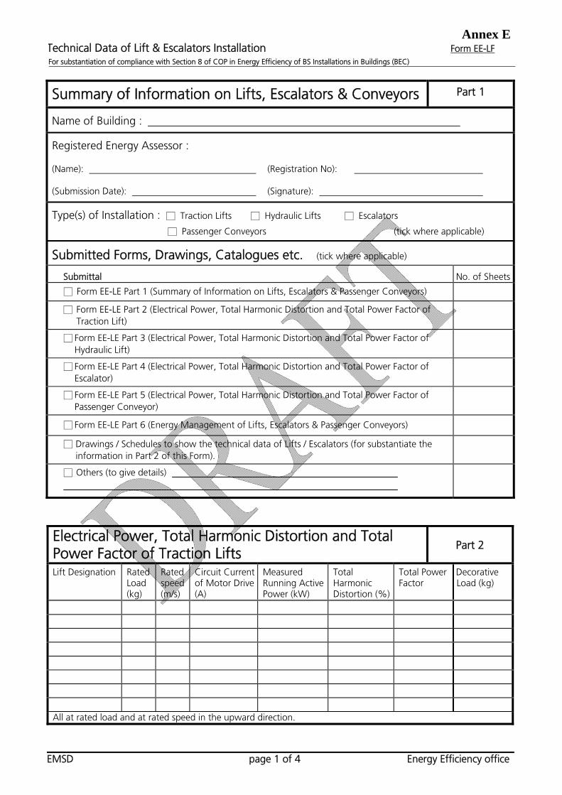
Annex ETechnical Data of Lift & Escalators Installation Form EE-LF For substantiation of compliance with Section 8 of COP in Energy Efficiency of BS Installations in Buildings (BEC)
EMSD page 1 of 4 Energy Efficiency office
Summary of Information on Lifts, Escalators & Conveyors Part 1
Name of Building :
Registered Energy Assessor :
(Name): (Registration No):
(Submission Date): (Signature):
Type(s) of Installation : □ Traction Lifts □ Hydraulic Lifts □ Escalators
□ Passenger Conveyors (tick where applicable)
Submitted Forms, Drawings, Catalogues etc. (tick where applicable)
Submittal No. of Sheets
□ Form EE-LE Part 1 (Summary of Information on Lifts, Escalators & Passenger Conveyors)
□ Form EE-LE Part 2 (Electrical Power, Total Harmonic Distortion and Total Power Factor of Traction Lift)
□ Form EE-LE Part 3 (Electrical Power, Total Harmonic Distortion and Total Power Factor of Hydraulic Lift)
□ Form EE-LE Part 4 (Electrical Power, Total Harmonic Distortion and Total Power Factor of Escalator)
□ Form EE-LE Part 5 (Electrical Power, Total Harmonic Distortion and Total Power Factor of Passenger Conveyor)
□ Form EE-LE Part 6 (Energy Management of Lifts, Escalators & Passenger Conveyors)
□ Drawings / Schedules to show the technical data of Lifts / Escalators (for substantiate the information in Part 2 of this Form).
□ Others (to give details)
Electrical Power, Total Harmonic Distortion and Total Power Factor of Traction Lifts
Part 2
Lift Designation Rated Load (kg)
Rated speed (m/s)
Circuit Current of Motor Drive (A)
Measured Running Active Power (kW)
Total Harmonic Distortion (%)
Total Power Factor
Decorative Load (kg)
All at rated load and at rated speed in the upward direction.

Annex ETechnical Data of Lift & Escalators Installation Form EE-LF For substantiation of compliance with Section 8 of COP in Energy Efficiency of BS Installations in Buildings (BEC)
EMSD page 2 of 4 Energy Efficiency office
Electrical Power, Total Harmonic Distortion and Total Power Factor of Hydraulic Lifts
Part 3
Lift Designation Rated Load (kg)
Rated speed (m/s)
Circuit Current of Motor Drive (A)
Measured Running Active Power (kW)
Total Harmonic Distortion (%)
Total Power Factor
Decorative Load (kg)
All at rated load and at rated speed in the upward direction.
Electrical Power, Total Harmonic Distortion and Total Power Factor of Escalators
Part 4
Motor Drive Circuit Current (A)
Measured Running Active Power (kW)
Escalator Designation
Rise of Escalator (m)
Step width (mm)
Rated Speed (m/s) # @ # @
Total Harmonic Distortion (%) #
Supply from feeder circuit ? (yes or no)
Total Power Factor @
Non-public Service
Public Service #: at no load and rated speed condition @: at brake load condition
Annex ETechnical Data of Lift & Escalators Installation Form EE-LF For substantiation of compliance with Section 8 of COP in Energy Efficiency of BS Installations in Buildings (BEC)
EMSD page 3 of 4 Energy Efficiency office
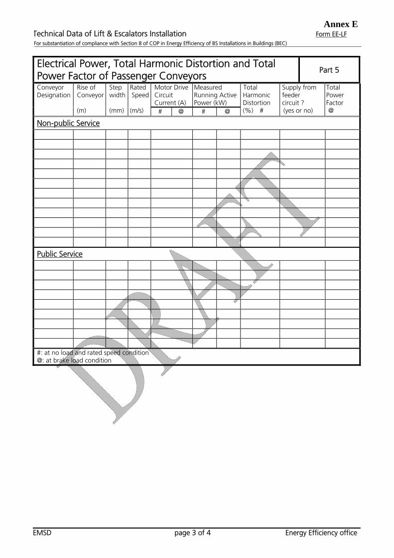
Electrical Power, Total Harmonic Distortion and Total Power Factor of Passenger Conveyors
Part 5
Motor Drive Circuit Current (A)
Measured Running Active Power (kW)
Conveyor Designation
Rise of Conveyor (m)
Step width (mm)
Rated Speed (m/s) # @ # @
Total Harmonic Distortion (%) #
Supply from feeder circuit ? (yes or no)
Total Power Factor @
Non-public Service
Public Service #: at no load and rated speed condition @: at brake load condition

Annex ETechnical Data of Lift & Escalators Installation Form EE-LF For substantiation of compliance with Section 8 of COP in Energy Efficiency of BS Installations in Buildings (BEC)
EMSD page 4 of 4 Energy Efficiency office
Energy Management of Lifts, Escalators & Passenger Conveyors
Part 6
LIFTS
(tick/delete as appropriate)
Zone Designation Lift Bank with DC-MG motor drive
Energy Management Provision of Metering Devices or provisions for connecting measuring devices for Lift Bank**
Yes/No Standby mode
Switch off Ventilation when idling more than 2 minutes
Voltmeter Ammeter
kWh Total Power Factor
Power Maximum Demand
Connection points for the above meters
Yes/No Standby mode
Switch off ventilation when idling more than 2 minutes
Voltmeter Ammeter
kWh Total Power Factor
Power Maximum Demand
Connection points for the above meters
Yes/No Standby mode
Switch off ventilation when idling more than 2 minutes
Voltmeter Ammeter
kWh Total Power Factor
Power Maximum Demand
Connection points for the above meters
Yes/No Standby mode
Switch off ventilation when idling more than 2 minutes
Voltmeter Ammeter
kWh Total Power Factor
Power Maximum Demand
Connection points for the above meters
ESCALATORS / CONVEYORS (tick/delete as appropriate)
Group Designation Number of Escalators/Passenger Conveyors in Group
Provision of Metering Devices or provisions for connecting measuring devices for Group of Escalators/Passenger Conveyors
Voltmeter Ammeter
kWh Total Power Factor
Power Maximum Demand
Connection points for the above meters
Voltmeter Ammeter
kWh Total Power Factor
Power Maximum Demand
Connection points for the above meters
Voltmeter .. Ammeter
kWh Total Power Factor
Power Maximum Demand
Connection points for the above meters
Annex F Technical Data of Performance-based Approach Form EE-PB For substantiation of compliance with Section 9 of COP in Energy Efficiency of BS Installations in Buildings (BEC)
EMSD page 1 of 7 Energy Efficiency Office
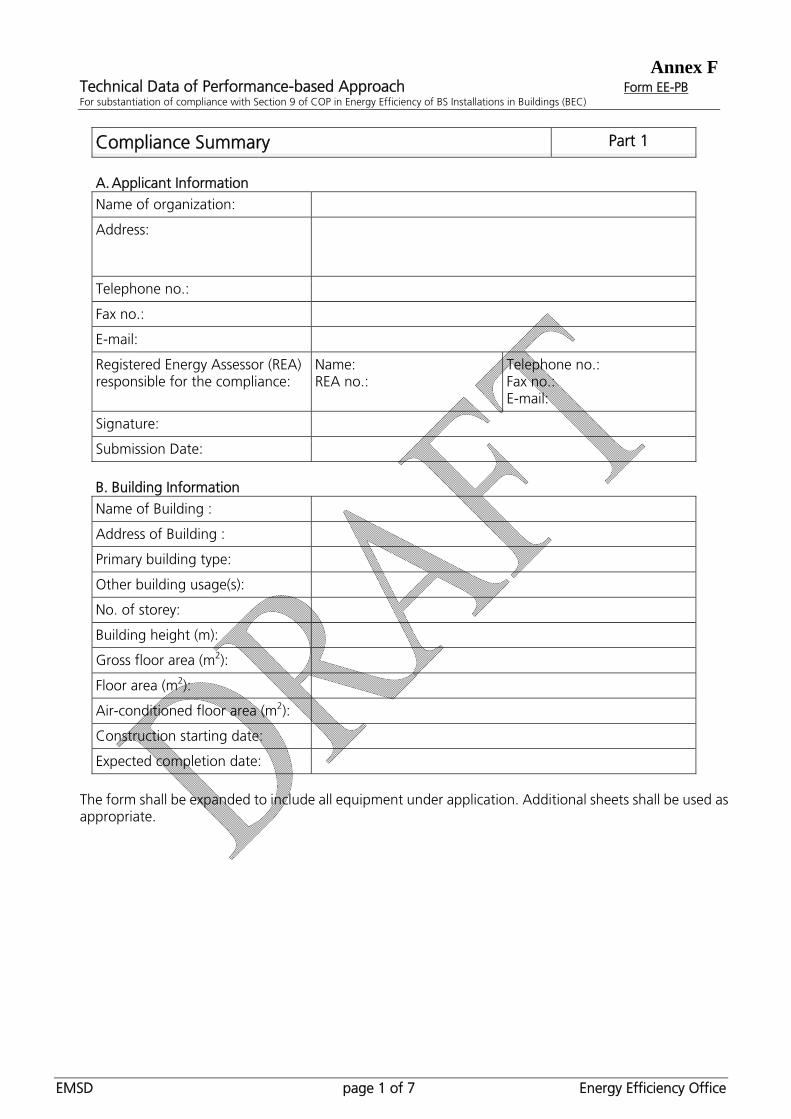
Compliance Summary Part 1
A. Applicant Information
Name of organization:
Address:
Telephone no.:
Fax no.:
E-mail:
Registered Energy Assessor (REA) responsible for the compliance:
Name: REA no.:
Telephone no.: Fax no.: E-mail:
Signature:
Submission Date:
B. Building Information
Name of Building :
Address of Building :
Primary building type:
Other building usage(s):
No. of storey:
Building height (m):
Gross floor area (m2):
Floor area (m2):
Air-conditioned floor area (m2):
Construction starting date:
Expected completion date:
The form shall be expanded to include all equipment under application. Additional sheets shall be used as appropriate.

Annex F Technical Data of Performance-based Approach Form EE-PB For substantiation of compliance with Section 9 of COP in Energy Efficiency of BS Installations in Buildings (BEC)
EMSD page 2 of 7 Energy Efficiency Office
C. Summary of Building Energy Performance
Designed Building Reference Building
Design energy consumption (kWh) -----
Total energy budget (kWh) -----
Breakdown of energy usage (kWh): - Area lights - Miscellaneous equipment - Space cooling - Space heating - Ventilation fans - Pumps - Other energy uses (pls. specify)
Energy use intensity (kWh/m2/year) (based on gross floor area)
D. Renewable or Recovered Energy Have you considered “renewable energy” or “recovered energy” and excluded it in the design energy consumption? Yes / No * (* delete where applicable) If yes, please provide detailed information and calculation for the “renewable energy” or “recovered energy”. Use additional sheets if necessary.
The form shall be expanded to include all equipment under application. Additional sheets shall be used as appropriate.

Annex F Technical Data of Performance-based Approach Form EE-PB For substantiation of compliance with Section 9 of COP in Energy Efficiency of BS Installations in Buildings (BEC)
EMSD page 3 of 7 Energy Efficiency Office
Basic Requirements Checklist Part 2
1. Building Envelope
Building (Energy Efficiency) Regulation Cap.123 Sub. Leg. M
Shading coefficient of window glasses shall be not less than 0.25.
2. Lighting Minimum allowable luminous efficacy Maximum allowable lamp control gear loss Interior lighting control
3. HVAC
Air Side System System load design Separate distribution system Air leakage limit on ductwork
Water Side System Pumping system variable flow Friction loss
Control Temperature control Humidity control Zone control Off hours control
Insulation Piping insulation Ductwork and AHU casing insulation
4. Electrical
Power Distribution in Buildings High voltage distribution Minimum transformer efficiency Locations of distribution transformers and main LV switchboards Main circuits Feeder circuits Sub-main circuits Final circuits
Efficient Utilization of Power Motors and drives Power factor improvement
Power Quality Maximum total harmonic distortion Balancing of single-phase loads
Metering and Monitoring Facilities Main circuits Sub-main and feeder circuits

Annex F Technical Data of Performance-based Approach Form EE-PB For substantiation of compliance with Section 9 of COP in Energy Efficiency of BS Installations in Buildings (BEC)
EMSD page 4 of 7 Energy Efficiency Office
Basic Requirements Checklist Part 2
5. Lift & Escalator
Lifts Maximum allowable electrical power Energy management of lift cars Total harmonic distortion of motor drive systems Total power factor of motor drive systems
Escalators & Passenger Conveyors Energy management of escalators & passenger conveyors Maximum allowable electrical power of escalators & passenger
conveyors Total harmonic distortion of motor drive systems Total power factor of motor drive systems
[Support Documentation]
Description of document No. of pages
The form shall be expanded to include all equipment under application. Additional sheets shall be used as appropriate.

Annex F Technical Data of Performance-based Approach Form EE-PB For substantiation of compliance with Section 9 of COP in Energy Efficiency of BS Installations in Buildings (BEC)
EMSD page 5 of 7 Energy Efficiency Office
Numerical Method for Building Energy Analysis Part 3 1. General Information
Name of software/method:
Software version number:
Software release number (if any):
Name of software license owner: 2. Software Developer/Supplier
Organization that developed the software:
Organization that supplied the software: 3. Climatic Data
Climatic data used for the analysis:
Format and nature of the climatic data: 4. Systems or Equipment Not Yet Determined But Assumed
Items Description
5. Other Modeling Assumptions
Items Description
6. Limitations of the Software/Method
Items Description
[Support Documentation]
Description of document No. of pages
Input building description file (printed and electronic format)
Output reports file (printed and electronic format)
The form shall be expanded to include all equipment under application. Additional sheets shall be used as appropriate.
Annex F Technical Data of Performance-based Approach Form EE-PB For substantiation of compliance with Section 9 of COP in Energy Efficiency of BS Installations in Buildings (BEC)
EMSD page 6 of 7 Energy Efficiency Office
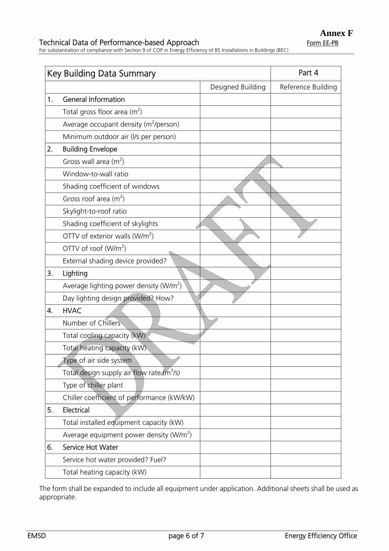
Key Building Data Summary Part 4
Designed Building Reference Building
1. General Information
Total gross floor area (m2)
Average occupant density (m2/person)
Minimum outdoor air (l/s per person)
2. Building Envelope
Gross wall area (m2)
Window-to-wall ratio
Shading coefficient of windows
Gross roof area (m2)
Skylight-to-roof ratio
Shading coefficient of skylights
OTTV of exterior walls (W/m2)
OTTV of roof (W/m2)
External shading device provided?
3. Lighting
Average lighting power density (W/m2)
Day lighting design provided? How?
4. HVAC
Number of Chillers
Total cooling capacity (kW)
Total heating capacity (kW)
Type of air side system
Total design supply air flow rate (m3/s)
Type of chiller plant
Chiller coefficient of performance (kW/kW)
5. Electrical
Total installed equipment capacity (kW)
Average equipment power density (W/m2)
6. Service Hot Water
Service hot water provided? Fuel?
Total heating capacity (kW)
The form shall be expanded to include all equipment under application. Additional sheets shall be used as appropriate.

Annex F Technical Data of Performance-based Approach Form EE-PB For substantiation of compliance with Section 9 of COP in Energy Efficiency of BS Installations in Buildings (BEC)
EMSD page 7 of 7 Energy Efficiency Office
List of Energy-related Features for Trade-off Part 5
Features Description
[Support Documentation]
Description of document No. of pages
The form shall be expanded to include all equipment under application. Additional sheets shall be used as appropriate.