Embed Size (px)
Citation preview

5/10/2018 Building Firearms by Harold Hoffman (Action Book Publishers) - slidepdf.com
http://slidepdf.com/reader/full/building-firearms-by-harold-hoffman-action-book-publishers 1/81
BUILDING FIREARMS
BUILDING FIREARMS
Copyright (c) 2000 Harold Hoffman
We have many good books on Gunsmithing, Knife making, History, Out of date, and Crafts
books. The purpose is to give you the basic information on subject that is covered here. Ihope you enjoy and learn from these books. H. Hoffman
All rights reserved. No parts of this publication may be reproduced or transmitted in any formor by any means, electronic or mechanical, including photocopy, recording, or any
information storage and retrieval system, without the written consent of the publisher.
Action Books
7174 Hoffman Rd.
San Angelo, TX. 76905Phone/Fax 915-655-5953
EmailHome Site
1

5/10/2018 Building Firearms by Harold Hoffman (Action Book Publishers) - slidepdf.com
http://slidepdf.com/reader/full/building-firearms-by-harold-hoffman-action-book-publishers 2/81
BUILDING FIREARMS
INTRODUCTION
This book will give you the general idea and information on building the simple guns that arelisted below. With the blueprints you will be able to turn out a working model. The frames for
the guns can be machined from steel or cast from aluminum or brass. I have listed severalmethods in the following chapters.
You will need most if not all of the equipment listed in Equipment and Tools listed below.Building firearms is not difficult, but if you plan to make more than one I would suggest
making a completed frame as a pattern and casting the frame. The frames can be madefrom Aluminum or Brass for 22's or any low-pressure cartridges.
Above all, be careful when making and test firing any weapon. I cannot accept responsibility
for accidents caused by a person not being careful when shooting or test firing any weapon.
Rifled barrels can be gotten from old 22 barrels and turned to the correct size. Therefore, I
will not go into the making of barrels here.
2

5/10/2018 Building Firearms by Harold Hoffman (Action Book Publishers) - slidepdf.com
http://slidepdf.com/reader/full/building-firearms-by-harold-hoffman-action-book-publishers 3/81
BUILDING FIREARMS
TURNING STEEL
Turning stock usually makes up most lathe work. The work usually is held between centers or in a chuck, and a right-hand turning tool is used, so that the cutting forces, resulting from
feeding the tool from right to left, tend to force the work piece against the head stock and thusprovide better work support.
TEST BAR OR WIGGLER BAR
Before you start the turning operation, set the tail stock back to 000 using a 18-inch bar that
is turned to exactly the same diameter on each end. To make this bar, get a 1-inch bar 18inches long, center it and set it up between centers.
Make a light pass and check both ends to see if they measure the same. If not, adjust the tail
stock and make another pass. Repeat the above operations until the bar measures the same
on both ends.
This bar, you save, as you will be using it again each time you true up the tail stock. Once youhave the bar completed, all that is necessary is to put it between centers. Clamp a dial
indicator to the carriage on the lathe.
With the plunger of the indicator on the bar, start from the head stock end (without the lathe
being turned on) and move the carriage to the tail stock end. If there is any difference in size,adjust the tail stock and repeat until the dial indicator reads the same on each end.
3

5/10/2018 Building Firearms by Harold Hoffman (Action Book Publishers) - slidepdf.com
http://slidepdf.com/reader/full/building-firearms-by-harold-hoffman-action-book-publishers 4/81
BUILDING FIREARMS
THREAD CUTTING IN A LATHE
Set the lathe for a 14 TPI feed, put it in back gear drive and you are ready to cut the threads.The tool is set so its centerline is at a right angle to the axis of the work piece. This setting
can be obtained by the use of the center gage as shown.
When the tool point fits uniformly into the v notch of the gage, the tool is at a 90ÿ angle.
The cutting tool is ground to the shape required for the form of screw thread being cut.
For cutting 60' V threads, a center gage is used for checking the angle when grinding the tool
to shape.
In cutting a right-hand exterior thread, the compound is turned in the direction of the head
stock and set at an angle of 29'.
NOTE: The point of the tool should be at the same elevation as the centerline of the work
piece.
The compound slide is set to an angle of 60', and the tool is set square with the work, usingthe ÿVþ notch of the thread gauge to set the tool. The point of the tool must be at the same
height as the lathe centers. The tool is run up to the work with the cross feed, and thecross-feed stop is set to always bring the cross feed back to the same position after backing
out the tool to return for another cut.
The compound slide is used to feed the tool into the work. By feeding the tool on the 60'
angle to which the compound slide is set, the tool cuts on one side only, and it can be given aside rake to make the chip clear the thread groove. If the tool is fed in square with the work, it
must cut on both sides. No side rake can be used, and the two opposing chips will interfereand jam in the cut.
The compound is adjusted so the micrometer dial on its collar is at zero. The tool is then
4

5/10/2018 Building Firearms by Harold Hoffman (Action Book Publishers) - slidepdf.com
http://slidepdf.com/reader/full/building-firearms-by-harold-hoffman-action-book-publishers 5/81
BUILDING FIREARMS
brought into contact with the work piece by adjusting the cross-slide and setting its
micrometer dials to zero. All adjustments for depth of cut can be made from these settings.
It is a practice to use both the cross-slide, and the compound. The tool is backed off the work
piece and the carriage is moved to where the tool is, at a point beyond the end of the workpiece. The cross-slide is then advanced until the micrometer dial reads the same as where
the tool was touching the work piece.
Next, the compound is advanced .002 to .003þ and a trial cut is taken. At the end of the cut,
the cross-slide is backed off and the tool returned to its starting point. The cross-slide is thenadjusted to its zero reading and the compound advanced a distance equal to the next cut.
The operation is repeated until the proper depth of thread is obtained.
The carriage is attached to the feed screw by closing the half-nuts. There is a safety interlock
between the friction feed for turning and the half-nuts for thread cutting, so the two cannot be
engaged simultaneously, which would wreck something.
At the end of each cut, the half-nuts are opened, and the tool is withdrawn from the cut, so the
carriage can be returned to the start for another cut. To be successful you must work quicklywith both hands, back the tool out with one hand while you open the half nuts with the other.
When you return the tool for another cut, advance the compound slide by the amount of thechip. Never change the setting of the cross-feed stop after you have started to cut a thread or
you will throw the tool out of alignment with previous cuts. If the tool is not withdrawn from the
cut, the backlash of the feed gears would leave the tool out of line with the thread and if thelathe was reversed, the tool would damage the thread.
If your lathe is not equipped with a thread cutting dial, you must reverse the lathe to return the
tool to the start for another cut. Without the thread dial, the half-nuts cannot be opened untilthe thread is completed.
The thread-cutting dial indicator is a dial geared to the lead screw. When the carriage is
5

5/10/2018 Building Firearms by Harold Hoffman (Action Book Publishers) - slidepdf.com
http://slidepdf.com/reader/full/building-firearms-by-harold-hoffman-action-book-publishers 6/81
BUILDING FIREARMS
stationary, the dial revolves, but when the carriage is cutting a thread, the dial is still. There
are several graduations on the dial, each numbered. As the dial revolves, the half nuts areclosed when the correct number comes up to the index mark. For most even numbered
threads, there are several places on the dial that can be used to close the half nuts. For odd-numbered threads there is only one position, and the half-nuts must always be closed on
the same number used to start the first cut.
Start the first cut, close the half-nuts on the number ÿ1þ line of the dial and feed the tool with
the compound until the tool just scratches a fine line, indicating the thread. Shut down the
lathe and test this line with the thread-pitch gauge to see that the lathe is cutting correctly. Thecross feed of the carriage must always be up tight to the cross-feed stop before moving thetool with the compound feed.
When you are getting close to the final size, use a pre cut nut (which you can get from a
factory loading die) to check the size. If the nut will not screw on make another light pass andtry again. When the nut will just screw on, make two or three additional passes at the same
setting to finish cleaning up the threads.
Lock the spindle and with plenty of oil on the tap work it in with a small wrench, backing it off
about every full turn. A cut off tool is used to cut off these nuts so they will be cut straight.
6
5/10/2018 Building Firearms by Harold Hoffman (Action Book Publishers) - slidepdf.com
http://slidepdf.com/reader/full/building-firearms-by-harold-hoffman-action-book-publishers 7/81
BUILDING FIREARMS
EQUIPMENT AND TOOLS
In the introduction, I listed a few machines that are needed, to make what you need. What isneeded will allow you to make the necessary parts for the guns and parts listed below.
LATHE
Your lathe should have at least a 3-foot bed, but a 6-foot bed is better if the spindle hole is
smaller than 1 1/2". The hole through the head stock should be at least 1 1/2 inch, as youwill need to center the barrel blank in the head stock.
There will need to be a collar on each end of the head stock so the blank can be centered.The collars will need to be tapped for 4-1/4 inch set screws, which will be used to center the
blank.
The lathe should be able to turn at least 2000 rpm or higher. It should have tapered bearingsin the head stock spindle.
OIL PAN
There should be some type of oil pan under the ways to catch the returning cutting oil, so it
can be strained before it is returned to the oil reservoir. This tray should extend full length of the lathe.
For boring barrels, you will need a pump that will turn out at least 400 lbs. of oil pressure.This pressure is needed to clear the chips. More on this later.
TOOL POST GRINDER
If you are going to make your tools, such as reamers and other special tools or cutters, a tool
post grinder is necessary. With a tool post grinder, you can cut your expenses down to avery small percentage of what it would be if you had to buy them or have them special made.
You will probably not be able to buy any tools for making shotgun barrels so most will have tobe made.
You will be able to grind your own reamers and your own chambering reamers. In general,
be able to make any gauge of barrel with any desired chambering.
MILLING MACHINE
You will need a milling machine with an indexing attachment for making reamers, however amilling attachment for a lathe should work. A vertical mill would be the best choice, as you
can do much gun work with it. You will also need a coolant pump.
7

5/10/2018 Building Firearms by Harold Hoffman (Action Book Publishers) - slidepdf.com
http://slidepdf.com/reader/full/building-firearms-by-harold-hoffman-action-book-publishers 8/81
BUILDING FIREARMS
This can be from an air conditioner pump, the evaporative type.
This will be needed in some cases when you grind the reamers. The coolant that you shouldis a water-soluble type that can be found at any machine supply house or oil bulk plants.
A good small mill can be bought from wholesale tools. See listing at back of manual under suppliers.
DRILL PRESS
Most shops have these. You will need a drill press for most of your fixture making. There
will be quite a few fixtures to be made to drill barrels, and ream barrels.
SHAPER
A shaper is not a necessary item to have but it will save quite a bit of time in making thenecessary fixtures that will be needed.
Most of the work that can be done on a shaper can be done on a milling machine.
However, some special shapes can best done with a shaper. It is easy to shape a lathe bitto what you want rather than to try to reshape a milling cutter.
SAWS
A good band or cut off saw is necessary when you are working with barrel steel. It gets oldvery quick cutting off a 1-1/4 bar steel with a hacksaw. It will come in handy also in thefixtures that you will be making.
Wholesale Tool has a good one that works as a cut off saw or a vertical band saw.
HEAT TREAT FURNACE
This is absolutely necessary to have. There are many small furnaces available on themarket that would work for what we want. It should go up to at least 2300 degrees, if you are
planning working with high-speed steel.
I have found that oil hardening tool steel (O1) works just about as good. You will need to
have good control to hold precise temperatures of the oven. This can be used to draw thetemper of the reamers and cutters also. The furnace can be made easy, and a blower from
a vacuum cleaner can provide the air. This is well covered in the book Barrels & Actions or
The Gunsmith and Tool Making Book.
8

5/10/2018 Building Firearms by Harold Hoffman (Action Book Publishers) - slidepdf.com
http://slidepdf.com/reader/full/building-firearms-by-harold-hoffman-action-book-publishers 9/81
BUILDING FIREARMS
MEASURING AND LAYOUT TOOLS
The following listing includes all the tools and instruments of this category that are essential togood Gunsmithing and tool making. Some of these precision items are a bit on the
expensive side when one has to go out and buy them all at once.
Considering the years of good service they will render, if properly taken care of, one can
scarcely consider them as being costly.
MICROMETER
You will need a micrometer from 0 to one inch, and one to two inches. They should be of atype so you can read down to ten thousandth of an inch.
MICROMETER (DEPTH)
Most of these come equipped with three interchangeable rods giving a range of
measurement from 0-3 inch by thousandths of an inch.
MICROMETER (INSIDE AND OUTSIDE)
These should have a capacity of at least 6" and equipped to give a reading in thousandths.
GAUGES
Some of the gauges that will be needed are a bore gauge for measuring the finished reamed
bore of the rifle barrel. There should be a gauge for each caliber that you make.
Each gauge should have a go and no go gauge on it. They can be turned out on a lathe.
The no go gauge should be .015 larger than the go gauge.
HEAD SPACE GAUGES
You will also need also head space gauges for each of the gauges you chamber for in theshop. They can also be made in the shop.
ANGLE AND RADIUS GAUGE
Another of the gauges that you will need will be angle and radius gauges. These are not used
to often, but they do come in handy when you need them. You will need a thread gauge, as inevery barrel you pull you will have to know how many threads per inch there is.
LEVELS
9

5/10/2018 Building Firearms by Harold Hoffman (Action Book Publishers) - slidepdf.com
http://slidepdf.com/reader/full/building-firearms-by-harold-hoffman-action-book-publishers 10/81
BUILDING FIREARMS
You will need a very accurate machinist level, one that will have the adjustable degree base;
so correct angles can be achieved.
TOOL STEEL
You will need a good supply of tool steel, (oil Hardening) for your reamers. You canexperiment with different makes until you find what will fit your needs. In 30 years, I have found
O1 hard to beat.
SILVER SOLDER
You will need a good high strength, low melting point silver solder. As you can see from theabove, that most shops have about all the machines needed to make rifle barrels, except for
a few specialize tools and machines.
10

5/10/2018 Building Firearms by Harold Hoffman (Action Book Publishers) - slidepdf.com
http://slidepdf.com/reader/full/building-firearms-by-harold-hoffman-action-book-publishers 11/81
BUILDING FIREARMS
MAKING PARTS AND GUNS
11

5/10/2018 Building Firearms by Harold Hoffman (Action Book Publishers) - slidepdf.com
http://slidepdf.com/reader/full/building-firearms-by-harold-hoffman-action-book-publishers 12/81
BUILDING FIREARMS
This is one of the interesting parts of making guns, is the making of the actual parts. There
will be some machines that you will need to do the machining of the parts. A band saw willcome in handy for cutting out the working parts of the gun. There are many blue prints below
that will allow you to make simple guns.
Probably the single most important machine will be the Milling Machine, as about 90% of the
work will be done on it. There are many types of Milling Machines available to the craftsman.The most common is the Horizontal Mill, and in most cases you will be able to do all the
necessary operation that is needed to make a firearm.
Probably the most common is the Bridgeport Milling machine. It is an excellent machine, and
many accessories are available for it. Wholesale Tool makes an excellent Milling/Drillingmachine, and I have found that most work of the can be done on it, if you have the
accessories with it.
There are a few hobby mills, but in most cases they are to light to do a satisfactory job,except miniature work. If you own a medium size Mill, it should be OK for most of the
operation described in the book.
Another possibility is the Milling Attachment for the Lathe. These are an excellent substitute
for the full size Milling Machine, but they are limited to what they can do.
ACCESSORIES FOR THE MILL
You will need a good assortment of End Mills, as well as Woodruff Cutters, and other types of
cutters. A good Fly Cutter comes in handy for removing excess metal, or making an octagonbarrel, and will take the place of some other milling operations.
MILLING VISE
A milling Vise is one of the most important pieces of equipment for the Milling Machine. It willbe used almost daily, and can hold other fixtures while machining the parts. Many of the
fixtures and jigs can be supported in the vise.
ROTARY TABLE
A Rotary Table is also the next most useful piece of equipment. Many of the parts will be
made on the Rotary Table, both in the vertical as well the horizontal position. With it parts canbe machined with out removing them from the mill, as an example the octagon barrel.
ANGLE PLATE
12

5/10/2018 Building Firearms by Harold Hoffman (Action Book Publishers) - slidepdf.com
http://slidepdf.com/reader/full/building-firearms-by-harold-hoffman-action-book-publishers 13/81
BUILDING FIREARMS
With the angle plate clamped to the bed of the mill, you will be able to machine, or drill holes
at any angle on the part. The angle plate is not used that much, but it does come in handy attimes.
A good drill chuck for drilling, as well as collets in several sizes should be at hand. A goodsupply of cutting oil will help to maintain good tool life. You will need a few good measuring
tools, such as a dial indicator, edge finder, center finder, etc. Most of these tools can bepurchased from machinery suppliers, some of which are listed in the Appendix.
13

5/10/2018 Building Firearms by Harold Hoffman (Action Book Publishers) - slidepdf.com
http://slidepdf.com/reader/full/building-firearms-by-harold-hoffman-action-book-publishers 14/81
BUILDING FIREARMS
NOTES ON MAKING PARTS
Making the Frame will be the first item to start on, and if you look closely, you will see that inmost cases I have omitted the thickness of the parts. The reason for this is that the availability
of suitable steel in your area may be limited. Get the available steel and build the partsaround this. You should know this before you start on the frame.
Making the frame can be as simple as cutting out the parts, and then riveting or silver soldering them to together. If you plan to make more than one, by all means make a master
pattern out of wood or aluminum to be used as a pattern for investment casting.
The reason for this is the many different machining and drilling processes involved. However,
the basic barrel pattern could be made from wood, cast, and then the machining operationscompleted. The finish-machined barrel could then be used as the master pattern for the wax
mold.
On many short barrel guns, the barrel assembly works out very well cast. If you plan to castthe barrel assembly, be sure to center drill the pattern where you will drill it out for the liner
before making the master mold for wax. When completed, it will be a simple matter to center the barrel in the lathe and drill the barrel (see chapter on barrel turning.)
Sights, in most cases can be installed on the barrel after finishing, but if you want they can becast in one piece either separately or on the barrel. On the short barrel guns, the sights can
be cast with the barrel, which saves much machining time.
Any parts that will be used continually should be made from steel. This includes triggers,sears, barrel latches, hinges for the barrel, and extractors. Many parts can be cast and thenthe holes that are used continually bushed with a steel bushing.
14

5/10/2018 Building Firearms by Harold Hoffman (Action Book Publishers) - slidepdf.com
http://slidepdf.com/reader/full/building-firearms-by-harold-hoffman-action-book-publishers 15/81
BUILDING FIREARMS
STEPS IN MAKING PARTS
To be on the safe side in designing a firearm that will work right the first time you need to dothe following.
1. Cut out the outline of the frame from aluminum and leave it flat as cut. From this mainpattern you can fit all the parts, such as hammer, springs that has holes drilled through the
frame.
2. Determine what the thickness will be on the hammer and trigger.
3. Cut out the hammer and trigger from either aluminum or steel. Finish out these parts asclose as you can leave a little extra metal for final fitting. Drill the hinge or pivot holes in their
proper location.
4. Place these parts on the outside of the frame. The hammer and trigger pivot hole can bealready drilled at their exact locations if you want. Otherwise, with the parts on the frame (start
with the hammer) in the proper place, clamp the parts and drill a hole through the frame.Place a pin the correct size into the frame and place the hammer over it. You now have a
hammer that will rotate as it would in use.
5. Next locate where the trigger should be and repeat the above step. Once the trigger and
hammer are mounted on the frame, they can be hand fitted to work properly in relation toeach other.
6. On the inside of the frame can be machined Out to fit all the inside parts. Most of it can bemachined out using end mills, but in the corners you will probably have to square it up with a
file. When milling, use a slightly smaller mill than the finish width as in most cases if the partswere .250 thick and you use a .250 mill it would cut oversize. After the final milling is
completed, move the end mill over a few thousands for a cleanup pass. There should not beover .003 to .005 clearance when completed.
7. Take all the inside parts that you have made, and try them to be sure that they all fit, doing
any final fitting on the frame that is necessary. Make sure that you have sufficient room for thesprings.
15

5/10/2018 Building Firearms by Harold Hoffman (Action Book Publishers) - slidepdf.com
http://slidepdf.com/reader/full/building-firearms-by-harold-hoffman-action-book-publishers 16/81
BUILDING FIREARMS
SPRINGS
The springs can now be made for your gun. Soft spring stock can be purchased fromBrownells (see appendix) in various size and thickness. Springs will give you the most
problems until you learn how to temper them properly. Shape out the spring with a file andgrinder, smooth and polish it. Drill any holes that you need in it and then carefully bend it to
the shape that you need. Be careful that you do not twist the spring. Now you can heat treatthe spring.
HEAT TREATING THE SPRING
If the spring is small, it can be heat-treated with a butane torch, otherwise it must be done in a
heat treat furnace. You will need some quenching oil, which can also be purchase from
Brownells, otherwise use Olive Oil, or 5 to 10 weight machine oil.
On a small spring barely hold the thick part of the spring with a pair of needle nose pliers.
Light the Butane torch, and heat the spring to a cherry red, or about 1550 degrees andimmediately quench the spring into the oil. The process is the same for larger springs, as
well as for hammers, triggers, etc. After quenching, the part is glass hard and will breakeasily.
TEMPERING THE PARTS
Springs, you will find are easy to temper after you find out how to do it. Polish the spring to
get a bright polish, then carefully holding the spring with the Needle Nose Pliers start heating
the spring from the thick end.
Use a small flame on the torch and just play it on the metal. Watch the colors as you heat itup, as they will go from a straw to a dark blue, to a light gray blue. When the color reaches the
dark blue move the tip of the flame down the spring. The reason for going to dark blue amoving it down the spring is that as you move it down it goes to the light blue-gray.
If you hold it on the spring till it turned alight blue and moved it, you would go to the next level
of hardness and the spring would be too soft. I have found it wise to repeat the process twice,as when I have done this I have almost eliminated spring breakage.
Once the springs are tempered you will need to fit the springs to the action, and drill and tapthe frame to fasten the springs in place. When this is done, the hammer can be cocked, and
all the parts should work.
Make all the other parts and fit them as above. If you do not want to drill holes now, center
punch the places on the barrel or frame at the exact location. When you cast the frame or barrel, these punch marks will still be there and it will be a simple job to drill them.
Now with all the parts fitted, finish out the frame to the shape and polish it to a high finish.
16

5/10/2018 Building Firearms by Harold Hoffman (Action Book Publishers) - slidepdf.com
http://slidepdf.com/reader/full/building-firearms-by-harold-hoffman-action-book-publishers 17/81
BUILDING FIREARMS
Now you can use the finish part and make a mold for wax patterns and make a duplicate
frame as many times as you like.
17

5/10/2018 Building Firearms by Harold Hoffman (Action Book Publishers) - slidepdf.com
http://slidepdf.com/reader/full/building-firearms-by-harold-hoffman-action-book-publishers 18/81
BUILDING FIREARMS
CASE HARDENING
One of the oldest known heat-treating processes is carburizing. History tells us that swordblades and primitive tools were made by the carbonization of low-carbon wrought iron. When
you are making a firearm, case hardening is a good way to finish many of the parts. Color case hardening will give a very attractive finish.
The following carburizing processes are commonly used in industrial applications: (1) packcarburizing, (2) gas carburizing, and (3) liquid carburizing.
Most mild steels do not come with enough carbon to enable them to be hardened by heatingand quenching, as are the higher-carbon-content tool steels. However, if carbon is added to
the steel, it can be made to harden upon quenching. There are many methods of adding
carbon. In the processes, the heated steel absorbs the carbon from the outside. The interior of the metal does not absorb the added carbon and so remains soft after quenching. A hard
carbonous surface, or case, is formed on the metal.
Case-hardening is accomplished by impregnating the surface of steel with carbon, by
heating it at high temperatures while packed in an iron or steel box with proper carburizing
materials, or by heating the steel in potassium cyanide in an iron pot,
The only practical method for the home shop is one of the cyanide processes. Melted sodiumcyanide is a very good carbonizing agent, but it is also very dangerous to use.
There are several patented compounds on the market, such as Kasenit, Hard and Tuff, whichgive the same results and are safer to use. The steel is heated to a cherry red, then covered
with the hardening compound and allowed to soak in it. This will form a paper-thin case thatwill be glass-hard when quenched.
18
5/10/2018 Building Firearms by Harold Hoffman (Action Book Publishers) - slidepdf.com
http://slidepdf.com/reader/full/building-firearms-by-harold-hoffman-action-book-publishers 19/81
BUILDING FIREARMS
The case will not be thick enough for grinding. To form a case that can be ground, the steel
must be heated several times and let soak in the melted compound until cool after eachheating. In shops that do a lot of case hardening, the article is surrounded with the
carbonizing agent-bone charcoal, molten sodium cyanide, or a nitrogen atmosphere, andheld in a furnace at the carbonizing temperature until a case of the desired thickness has
formed upon it.
The various parts of gun parts such as guards, metal butt plates, etc., and the different parts
of locks, such as hammers, tumblers, triggers and plates, that the Gunsmith has to make willneed some type of hardening. Many gunsmiths, particularly those in the country, finish the
parts with a file and then hand polish. These parts can then be finished through the normalheat-treating, or case hardening.
Triggers, sears and various other small parts can be finish in this manner. As these parts are
almost always made of soft iron, they would soon wear and have to be repaired if nothardened.
The gunsmith will thoroughly case-harden the parts when they are fitted and finished, and willturn out a good piece of work that will wear as well as hardened steel. Some gunsmiths,
when such work is finished, heat it red hot, smear it with a good case hardening compoundsuch as Hard-tuff, and while hot, plunge it into cold water, letting it chill. This produces a
superficially hardness surface that is not" skin deep," and as soon as this surface becomesworn through use it will wear away rapidly.
If the casehardening of the experience Gunsmith, you will see that the surface of such workhas a fine grayish appearance, and in many places mottled with colored tints that are
pleasing and beautiful to the eye. On these parts the hardness is of such depth that it willwear for a long time. In fact it will wear better than hardened tool steel. The condition of the
case hardened part is that of a hardened steel surface stretched over and shrunk upon theiron body of the work.
It is stronger and tougher than steel, for it has the tenacity of iron for its interior. It has the
19

5/10/2018 Building Firearms by Harold Hoffman (Action Book Publishers) - slidepdf.com
http://slidepdf.com/reader/full/building-firearms-by-harold-hoffman-action-book-publishers 20/81
BUILDING FIREARMS
advantage of steel, in as much as it may be bent when cold to a limited degree, and case
hardened it will not break as readily as steel.
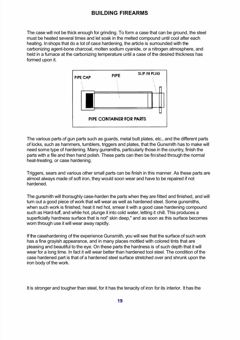
The easiest and Perhaps the best way to case harden gun work is to have a number of short
pieces of common gas pipe, such as will be adapted to the size or quantity of the work, andhave one end of these pieces securely plugged or capped. A best way is to have a thread on
the pipe and then screw on a plug, such as are used to close ends of gas pipe.
In the pack carburizing process, the operation is carried out by packing the steel in suitable
containers such as steel boxes or pots, with a carbonaceous material.
The substances used are generally commercial solid carburizers that vary in composition;
They generally consist of a hardwood charcoal to which an energizer, such as bariumcarbonate, has been bound by molasses or oil tar.
Mixtures of coke and charred leather, bone, and charcoal are also used. The energizer
usually represents about 20% of the mixture. To increase the rate of heat transfer through thecompound, an additional 20% is made of coke. Since the compound decomposes with use,
it is common practice to add 12% to 30% new material to used compounds for a newoperation.
In this process, the box, which is made of heat-resistant alloys, is packed and sealed tightly,then placed in the furnace and heated to between 1500o and 1750oR Within this range a
transformation takes place in the steel forming austenite which has the capacity to dissolvelarge amounts of carbon.
The best case-hardening is done by the pack-hardening method, that is, packing the articlesto be hardened in iron boxes in which the article is surrounded by powdered charcoal, coke,
leather or bone and heated at a rather low heat over a long period of time. This method givesa deeper hardening and the temperature is more easily controlled.
The time required varies with the size of the pieces. Temperatures may be held at 1550degrees Fahrenheit. Green bone should never be used as a carburizing material, as it
contains phosphorus. Pack the work with the powder, the same as bone dust. Bone black
may be used the same as bone-dust, but it is not as good, and will not give as good aresults. It is also dirty to use and to have around a shop.
Gun guards, straps and long pieces of work will become shorter after case-hardening, and itis best not to fit such pieces into the stock until after they are hardening.
Case-hardening by heating the articles in liquid potassium-cyanide to a temperature of 1562degrees Fahrenheit gives a quick and very even case, but it is superficial and won't stand
any further finishing after being case-hardened as the hardening will be cut through.
Cyanide salts are violent poisons if allowed to come in contact with wounds or scratches and
are fatal if taken internally. Poisonous fumes are generated when cyanides are brought into
20

5/10/2018 Building Firearms by Harold Hoffman (Action Book Publishers) - slidepdf.com
http://slidepdf.com/reader/full/building-firearms-by-harold-hoffman-action-book-publishers 21/81
BUILDING FIREARMS
contact with acids.
As the cyanide gives off deadly poisonous fumes, this type of case hardening should bedone in an open pot, under a hood attached to a flue with a good draft, and the operator
should stand back from the pot.
Cyaniding is a process that involves the case hardening of machined steel parts by heating
in contact with molten cyanide salt, followed by quenching in a salt bath, water, or mineral oil,depending upon the type of steel. The salt bath consists of a mixture of 30% sodium cyanide,
4-0% sodium carbonate, and 30% sodium chloride.
The cyaniding temperature is above the lower critical temperature of the steel, usually from
1400ý to 1600ýF. Direct quenching is employed. This process is capable of high production,as immersion periods require only 15 minutes to 2 hours. It requires about 30 minutes to
caseharden a part from 0.003" to 0.005". The maximum case depth is rarely more than
about 0.020". Avery thin surface case can be obtained by dipping in a powdered cyanide
mixture, followed by quenching.
CAUTION: A method of venting gases is a must during the operation and molten cyanide
should never be allowed to come in contact with sodium or potassium nitrates, used in
tempering operations, as the mixtures are explosive, extreme care is necessary at all timeswhen using the material
If you want to have an area of the work left soft and the other parts hardened, securely cover the places to be left soft, with a coating of moist clay, and this will prevent the hardening
material from coming in contact. It may also be observed that articles that are case hardened
will not rust so readily as those not so treated.
If the parts are quite thin, there may be a chance of there cracking by sudden chilling. Toprevent this the water may be warmed a little, or a film of oil may be spread on the water,
which will tend to prevent to fast cooling of the articles. If you want to have the work show thecolors or mottled tints as seen on some kinds of case hardened gun work, the surface of the
work before being put in the pipes containing the burnt leather, must be highly polished and
then buffed. The higher the finish the more brilliant will be the colors.
In using a commercial compound to case harden, the work heated and dipped in, or if the
work is large the compound must be spread over it. The work must be hot enough to fuse thecompound, and if it become cold by removing from the fire it must be reheated, removed
quickly from the fire and quenched is cold water.
Collect such articles cow's horns, or hoofs of either cows or horses, leather trimmings from
about the local shoe shops, old boots or shoes, and burn them until sufficiently charred toadmit of being easily pounded into a powder. Then finished up the parts to be hardened, and
ready for the final polish, place them in an iron box, and surround it completely on all sides bya packing of the powder. Pour into the box, until the powder is moist, a solution of common
salt. Then close the box and seal it until airtight, with wet and well-worked clay, then put it intothe furnace and heat the furnace up gradually until it becomes a cherry red. Do not bring the
21

5/10/2018 Building Firearms by Harold Hoffman (Action Book Publishers) - slidepdf.com
http://slidepdf.com/reader/full/building-firearms-by-harold-hoffman-action-book-publishers 22/81
BUILDING FIREARMS
heat any
22

5/10/2018 Building Firearms by Harold Hoffman (Action Book Publishers) - slidepdf.com
http://slidepdf.com/reader/full/building-firearms-by-harold-hoffman-action-book-publishers 23/81
BUILDING FIREARMS
SOLDERING AND BRAZING
Soldering is a method of joining two pieces of metal together with an alloy of lead and tin.Soldering, which is known as soft soldering is the process of fastening two pieces of metal
by means of an alloy having a fairly low melting point. When you want a low melting pointsolder bismuth is added. Lead has the highest melting point of the three solders. The
solders containing a high percentage of lead and a lower percentage of tin, or a highpercentage of lead and a low percentage of tin and bismuth have the highest melting point.
If you use lead it has a melting point of 620 degrees Fahrenheit, tin has a melting point of 445 degrees Fahrenheit. The most commonly used solder is called half-and-half. It is
composed of 50 percent lead and 50 percent tin, and has a melting point of 428 degrees
Fahrenheit. If you use a solder that is composed of 32 percent lead, and 15.5 percent tin52.5 percent bismuth it has a melting point of 205 degrees Fahrenheit. This is below the
boiling point of water as sea level.
In most cases, the craftsman or gunsmith does not have much use for solder except in
sweating ramps, barrel bands, scope base blocks or rear sights to a gun. When a persontries the first time to Saunders two pieces of metal together their biggest difficulty is to get a
solider to stick to the parts. Usually, instead of flowing and taking hold on the metal it usuallyformed little balls with roll off. Once a person learned how to apply solder, the solder will flow
evenly over the work and has amazing holding strength. The joint will not be a strong as silver soldering due to the greater softness, however it will resist any normal strain is likely to
receive and will remain solid until removed by melting. They also use this process at timeswhen they make tools, such as when you sweat two different pieces of steel together
temporarily for machining.
Probably the average gunshot will sweat on RAM front sights, swivel bands, and also slight
bases, as well as other different type of jobs. Every so often a target shooter will want the
telescope manning blocks on his rifle sweated-on, and this is a head someplace to use thevery soft solders. Just remember, that most of the bluing are blacking processes that are use
today will live lead devour lead it left in the bluing solution to long.
23

5/10/2018 Building Firearms by Harold Hoffman (Action Book Publishers) - slidepdf.com
http://slidepdf.com/reader/full/building-firearms-by-harold-hoffman-action-book-publishers 24/81
BUILDING FIREARMS
SWEATING
Sweating is a slightly different process than what you would use if you solder. It will approachbrazing in its strength when properly used in sweating of two pieces of steel together; each
piece is tinned, (this is giving a thin coating of solder to the parts that will be sweatedtogether). Then the pieces are placed face-two-face with the tinned surfaces in contact. They
are clamped tightly in this position, and are then heated with a torch so that the applied heatopens the pores of the steel.
When this happens, the solder enters these pores making a good joint between the twopieces. The clamped pieces are less clamped together until cool. Always remember in
either soldering or sweating, keep the parts stationary and together while lead joint is
cooling. Any movement of one-piece independent of the other that is being joined together causes the solder to crystallize in the joint, and when this happens its holding power
becomes week.
When you sweat two parts together the two surfaces that you want to join together should
make as perfect a contact with each other as possible. Contours of the two surfaces mustmatch closely to produce a good joint. When you solder, braze, or whales a joint the first
saying to do is make sure that the surfaces are clean. They have to be free of bluing, rust, oil,or anything except raw metal.
The surfaces need to be polished with and abrasive clothes and then forced or wiped withalcohol gasoline, or advances solution made specially for soldering. Before you join two
surfaces they must also be cleaned and not to highly burnished. You can scrape them with a
knife or scraper, or a median course Carborundum cloth to free the surface of any corrosion. Above all, the surfaces must be free of any grease.
After the surfaces are cleaned coat them with a flux to prevent oxidation. If you are using
steel, either one of two fluxes will serve the purpose. One of these is rosin that is usually
used in powder form. Spread this on the surface to be tinned and the heat of the iron used intinning the surfaces melts the rosin and flows it completely over the surface. If you want to
eliminate any danger of rust, rosin is a fluxed to use.
The second flux that you can use for steel is zinc chloride, which is made by dissolving zinc
chips or cuttings in hydrochloric acid. This flux is applied with a stiff brush over the complete
surface. This flux will cause corrosion and rust on surfaces adjacent to the sweated or soldered joint. The surfaces should be well washed with water or ammonia after the partshave cooled, which will prevent rusting.
SOLDERING IRON
The soldering iron that we use in tinning the surfaces should be of a large size, which is
normally a two pound copper iron. The solder should be well rubbed into the surface of thesteel by the iron and to do this the iron should be large enough to retain its heat for quite a
period of time. A small soldering iron will not do this, as it will cool too quickly. Soldering
24

5/10/2018 Building Firearms by Harold Hoffman (Action Book Publishers) - slidepdf.com
http://slidepdf.com/reader/full/building-firearms-by-harold-hoffman-action-book-publishers 25/81
BUILDING FIREARMS
irons can be purchased at most plumbing businesses.
The soldering iron should come to a point and the sides of this point should be square andflat. You should tin the iron on these flat surfaces up to and including the point of the
soldering iron. A block of salammoniac is use maintaining a coating of the soldering ironwith solder the soldering iron is filed until the point and the surfaces back of the point are
cleaned and smooth. The soldering iron is then heated, hot enough so that when you applythe sal-ammoniac the latter fumes and smokes melting under the tempter of the iron.
Small pieces of solder are dropped onto the block the Sal almanac and hot iron is rubbed onthese to give a coating of solder. When I can the point on a soldering iron hyper for to do this
by heating the copper and then flux seen it and rubbing against a bar solider until it is tinned.Flux is used to prevent oxidation of the surfaces that are to be joined until the solder flows,
and it is very vital to soldering and brazing. We use flux, it makes a solder take hold and
stick and can be any of a dozen types, has different metals and solders required differenttypes of flux's. Plain rosin, which is probably the world's oldest fluxing material, also remains
one of the best.
HEATING THE SOLDERING IRON
Win you heat of the soldering iron be sure to avoid overheating it, as this will burn androughened the surface of the iron. Scale will form on it through which the heat does not pass
very well to the surface being soldered. If you do overheat the iron, the iron must be filedcleaned in and then retained. When heating the iron, just before applying the solder, it should
be dipped into a liquid flux such as zinc-chloride. This brightens it and enables it to holdmore solder upon its surface.
SWEATING
There are many different types of solder which comes in all sorts of lead, can, and bismuth
alloys. The 50-50 solders, which is half tin and half lead is most common and will handlemost of the gunsmiths needs. When you sweat two pieces of steel together, such as a ramp
or barrel bands to a barrel, all bluing must be removed from the surface and from the inner
surface of the ramp or band if it is already blued. Put the ramp or band in place on the barreland mark around it surfaces with a sharp scribe. Remove the ramp or band, and using a
small scraper or file remove all bluing from the barrel within the scribe lines. If the ramp or band is blue on its inner surface, scrape all of the bluing off of this surface that will come in
contact with the barrel.
The barrel bands, or the ramp if it is equipped with a band that is circles the barrel will need
to be tinned on the inside also. You may have to use a smaller soldering iron to accomplishthis.
After all of the parts have been tinned, heat them with a torch such as a butane torch can usea cloth to wipe all the excessive solder when the torch has softened the solder sufficiently.
After cooling place the band or ramp on the barrel in the proper position, and if the item thatyou want to solder is a ramp, place a piece of sheet copper on the tail end of the ramp and
25

5/10/2018 Building Firearms by Harold Hoffman (Action Book Publishers) - slidepdf.com
http://slidepdf.com/reader/full/building-firearms-by-harold-hoffman-action-book-publishers 26/81
BUILDING FIREARMS
clamp it. This is done to draw the tail in of the ramp down tight to the barrel.
When soft soldering the parts were pieces they are usually clamped or wired together in thecorrect position and the proper flux is applied. In the gunshot, sweating has more use than
the other methods. There are many done processes which involve this system, and factories join the barrels of double-barrel shotgun together by sweating, for and lugs are often sweated
on as well as ventilated ribs. When everything is lined up OK, apply the heat with a butanetorch to the items that are being sweated on the barrel. Heat everything as evenly as
possible until solder began to run at the edges. If a clamp is use tightened, clamp a littlemore and hold the heat on the work a little bit longer, then shut off the torch and let everything
cool without moving it.
SMALL PARTS
Another method of tinning small parts when the inside of the ring is too small to get to with a
soldering iron is to heat that piece with a butane torch. After applying the flux, then apply wire
solder to the surface to be tinned. Turn the piece so that the solder coats the inside surfacecompletely. You can use either acid-core or rosin-core wire solder to tin the surfaces.
26
5/10/2018 Building Firearms by Harold Hoffman (Action Book Publishers) - slidepdf.com
http://slidepdf.com/reader/full/building-firearms-by-harold-hoffman-action-book-publishers 27/81
BUILDING FIREARMS
BRAZING
Brazing is a little different from soldering and is a method of joining two metals with moltenbrass. When you braze, a much higher heat than soldering is used. The metals that are to
be joined together must be red-hot so it's use it limited to parts that will not be injured by thehigh heat required. The advantage in using brass for brazing is that it will withstand heavy
strains, so long as it is not a bending strain at the point that is brassed.
Silver soldering or hard soldering is often confused with brazing but there is a big different
between the two processes. While brazing brass, which will become molten at about 1660degrees Fahrenheit. Silver-solders can be bought in many different mixtures requiring heat
from 700-800 degrees Fahrenheit's up to 2000 degrees Fahrenheit to become molten.
Brazing requires the heat of the acetylene torch to get a good joint, as the steel or iron partsthat are joined together must be brought to a good red heat at the joint. The parts that you
want to join must be thoroughly cleaned as they are brought up to red heat. A good flux isBorax in powder form that is sprinkled on the surface to act as a flux. Borax will melt and
cover the surfaces and the brazing spelter. Applied from a brass rod by the torch it isapplied to the joint or it will run into the smallest crevices. When doing this type of work the
piece should be turned so that the molten brass can run in from all sides. Borax we used asa flux will form a hard scale and may be ground off if there is excess material to be removed
when finished. It may also be removed by placing the piece in an acid pickle of one partssulfuric acid to 20 parts of water.
BRAZING OR HARD SOLDERING
One warning about brazing or hard soldering is that the process is not suitable for attaching
parts to barrel the receivers. Even if the bore of the barrel is protected by file hardeningcompound to prevent oxidation under the high heat, the heat may cause the barrel to develop
a kink in it. In most cases the heat treatment from the receiver and barrel will be removed
and hard soldering to a barrel is use the barrel may develop a kink in it. You can use brazingor hard soldering for making or repairing parts that are removed from the guns if the joint is
not visible when the part is in place. The brass and the joint will show and cannot be blued tomatch the other parts of the guns.
27

5/10/2018 Building Firearms by Harold Hoffman (Action Book Publishers) - slidepdf.com
http://slidepdf.com/reader/full/building-firearms-by-harold-hoffman-action-book-publishers 28/81
BUILDING FIREARMS
SILVER SOLDERING
Hard soldering or silver soldering is done with silver-brass alloy, which is usually supplied infine granulate form. It can be obtained in many different melding points. When attaching to
parts ribboned form of silver solder is usually the best to use, as a piece of the ribboned hisplace between the two parts that our planned to be joined together. Clean the parts
thoroughly and then coat with a paste made of Borax mixed with water. Clamp the partstogether tightly and then apply the heat until the silver solder melts. Leave the parts clamped
together until they are cool. Remove the Borax scale by placing the parts in the acid picklebath.
Usually, very little if any of the white silver solder will show at the edge of the joint is the
pieces are well fitted. Silver soldering is preferred for joint parts in gun work where the jointremains inside. Usually you can use silver solder to repair shotgun tangs, broken tangs or
any parts such as this. Silver soldering is use also for joining spring steel, and most other
brazing applications on firearms. Using silver solder is about the same as for brazing, butthe lower melding points of the more common alloys make it handle better for sweating the
joint.
I always use silver solder to attach the sweat-on ramp front sites for any rifle that I had to putsites on. I have found that it is more difficult to get an invisible joint line, due to the fact that
alloy cool so much faster than soft solder and will complicate thesqueezing-together-while-cooling process. However, you can be sure that the ramp will stay
on. You do have to be very careful when using silver solder that you do not apply too muchheat especially on light rifle barrels as it may cause scale to form in the bore. You silver
solder with melting points of 1200 degrees Fahrenheit or lower for mounting ramps on rifle
barrels.
28

5/10/2018 Building Firearms by Harold Hoffman (Action Book Publishers) - slidepdf.com
http://slidepdf.com/reader/full/building-firearms-by-harold-hoffman-action-book-publishers 29/81
BUILDING FIREARMS
PLASTER CASTING
If you decide to make a few special items, especially if the part is takes quite a while tomake, you will find it much easier to cast the parts, and then finish it to proper size.
Machining the parts takes many hours, and cast parts will save you many hours.
When you needed special parts for a rifle, pistol, knife, etc. you can probably make them out
of brass or aluminum. I have had to restore old rifles; mostly muzzle loaders that had brokentrigger guards or butt plates using the following methods. On making some parts, we can
make the pattern in two pieces from wood. It would take to much time to machine or file outthe needed parts.
When we needed a special part, I found some soft pine and whittled out the pattern that I
needed to have. I then got some gypsum plaster and made a mold. The wood pattern wassanded smooth, and we put a coat of lacquer on it to seal the wood.
When the pattern was ready to use, I added a good coat of paste floor wax to it to guaranteeit not sticking to the plaster. I poured some fine sand in a box, and then smooth it off, and
then the pattern were pressed one haft of its thickness into the sand. The patterns andparting surfaces are first sprayed with a suitable parting agent.
PLASTIC SLURRY
After mixing the powder with about 60 per cent water by weight, we pour the plaster slurry
into the flask, or surrounding frame, over the pattern. This should be done carefully to avoidthe entrapment of air. Be sure that the pattern is just at 2 of its depth, as if it is too deep, or
not deep enough, you will stick it in the mold. We then poured the plaster over the pattern,and in ten to thirty minutes, the plaster will become hardened. Then we must carefully remove
the patterns with lateral rapping.
After it was set up, I removed it from the sand and removed all the sand. I carefully removed
the pattern from the mold, taking care that we have not nicked the pattern. One method for
removing a pattern is to blow compressed air through a small hole that leads to theseparation surface between the plaster mold and the pattern. Later during pouring, the hole
29

5/10/2018 Building Firearms by Harold Hoffman (Action Book Publishers) - slidepdf.com
http://slidepdf.com/reader/full/building-firearms-by-harold-hoffman-action-book-publishers 30/81
BUILDING FIREARMS
may serve as a vent for the escape of air.
We must then heat the mold halves in an oven at or about 400 degrees F (this temperaturemay range from 300 to 1500 degrees F) to drive off all free water and convert the gypsum
again to CASO. This may require twenty or more hours.
While the mold halves are still hot from the drying oven, we quickly assemble them, plaster
cores are set if required, and we pour the mold. This is done without any delay to reduce theabsorption of moisture from the surrounding air. Moisture must be kept at a minimum,
because ordinary plaster molds have practically no permeability.
With plaster casting, producing castings with smoother surfaces and closer dimensional
tolerance is possible. Small dimensions on one side of it parting line can be held, if required, too within tolerances of + - 0.005 inch. The molds are made of gypsum plaster, and
they contain silica flour, silica sand, and other desired ingredients. Since water must not
affect the patterns, I usually made them out of metal (Aluminum) when I had several parts to
make.
There is a metal casting plaster available, which can be made permeable by whipping or mixing small air bubbles into the slurry with the use of a rapidly rotating, partially submerged
disk or blade. Many small air bubbles thus formed become interconnected when the mold isdried, providing sufficient permeability. Small castings in nonferrous metals (aluminum,
brass, bronze) can be produced in plaster molds with a surface finish as fine as .90 to .125inch and accuracy as close as 0.005 inch.
On small dimensions with an additional 0.002 inch per inch on larger dimensions. From
0.005 to 0.01.5 inch, we usually require more across the parting line. Molds are made of aspecial plaster
CORES
Cores, for holes and recesses, also can be made of the plaster composition. The size of theparts usually made in plasters molds ranges from a small fraction of an ounce to 10 lb. The
plaster causes slower cooling of the casting than would occur in sand molds. This slowness
has a tendency to improve the characteristics of bronze castings, but it is a disadvantagewith aluminum, giving properties that are somewhat lower than those with sand or shell mold
30

5/10/2018 Building Firearms by Harold Hoffman (Action Book Publishers) - slidepdf.com
http://slidepdf.com/reader/full/building-firearms-by-harold-hoffman-action-book-publishers 31/81
BUILDING FIREARMS
castings.
The pattern and the piece cost are much higher than for sand castings, but this cost is often justifiable because of the better finish and the elimination of machining. With these
permeable plaster molds; eliminating the chemically combined water from the gypsum is not
necessary, so drying requires less time.
One important application of plaster casting is the making of pressure cast fancy brasshandles for pistols or knives, and frames for guns. In this application, the molten aluminum is
first pored into a plaster lined, cylindrical metal receiver above the gate spruce
A asbestos disk about 1/16 inch, thick placed at the bottom prevents the metal from entering
the sprue. When the metal is just beginning to solidify, we cover the metal receiver, andcompressed air at or about 5 psi is admitted above it.
This breaks the asbestos disk and forces the solidifying metal quickly into the mold cavity.
This casting procedure produces smooth surfaces, excellent detail, and a minimum of shrinkage. Because of the limited refractoriness of gypsum, plaster casting is limited to
metals with pouring temperatures below 2150 degrees F. Since the heat conductivity of plaster is lower than that of molding sand, solidification of the castings will be slower.
We accomplish this without altering mold-cavity surface smoothness. Additional drying timemay be necessary to drive off free water. We recommend the use of metal patterns,
especially if we make more than one part. This process is well suited for intricately shapedcastings, especially of aluminum, where dimensional accuracy and surface smoothness are
the main concern.
A plumber's propane lead metal melting pot can be used to melt most alloys. If higher
temperature is required, you will need to make up a forge to melt the metal in. If we needmuch casting, a forge will speed up the casting. A split metal pattern is used, mounted on
plates and so designed that we that can remove it in two halves from the mold. We pour around this pattern and allow the plaster to harden.
Then we remove the pattern, and the two halves of the mold are baked in an oven to harden
31

5/10/2018 Building Firearms by Harold Hoffman (Action Book Publishers) - slidepdf.com
http://slidepdf.com/reader/full/building-firearms-by-harold-hoffman-action-book-publishers 32/81
BUILDING FIREARMS
them further, and to dry out all the moisture.
The nonferrous metals predominantly used for casting are alloys of copper, brass andbronze. Brass is generally identified by its color, and is said to be either red or yellow; color
can serve as an indication of the temperature required for the melt.
FLUXES
When we melt a copper-based metal in a crucible, some of the metal will combine withoxygen to form cuprous oxide. To convert the cuprous oxide back to metallic copper,
something has to be added to the melt to draw the oxygen. The one most commonly used for red metals is phosphor-copper: an alloy of copper and phosphorous. Phosphorous has such
an affinity for oxygen that it will ignite upon exposure to air: to make it stable enough to use,we alloy it with copper in the form of "shot." When introduced into the molten metal, the
copper melts and releases the phosphorous, which deoxidizes the cuprous oxide in the melt.
Nitrogen can carry out oxygen of a melt; we introduce the nitrogen gas (dry) through a hollowtube called a lance, which a rubber hose connects it to the gas cylinder. For red metals, the
lance is carbon; for aluminum, it is iron or steel. We insert the tube into the molten metal toowithin an inch or so of the bottom of the crucible.
A very good deoxidizer for copper is 5 ounces of black calcium boride powder. It is sealedin a copper tube 2 inches long, with the ends crimped closed. The best flux for melting down
extremely fine scrap pieces such as buffing or grindings is plaster of Paris.
There is another group of fluxes used to prevent the gases in the furnace from be exposed to
the molten metal and oxidizing it. Because they are used as a protective cover, they callthem cover fluxes. This flux is made by mixing five parts ground marble with three parts
sharp sand, one part borax, one part salt and ten parts charcoal. Another one, Mix equalparts of charcoal and zinc oxide, add enough molasses water to form a thick paste; roll the
paste into 2 inch balls and let them dry. When the alloy starts to melt, drop in enough balls tocover the surface.
Some fluxes are very, detrimental to refractory linings, often eating away a ring around the
inside of a crucible during a single heating. Check with your crucible and flux supplier to findout what is compatible before using a particular flux.
RED BRASS
Leaded red brass can be used with a simple gating system but it must be choked because
these alloys flow quite freely. We require risers for heavy casting sections, and the melt mustbe fast (under oxidizing temperatures). No cover flux is necessary for these alloys, especially
when clean materials are used. Deoxidize with 1 ounce of 15 percent phosphor-copper, for each 100 pounds of melt. Too much deoxidizer will make the metal too fluid, and can result
in dirty castings.
32

5/10/2018 Building Firearms by Harold Hoffman (Action Book Publishers) - slidepdf.com
http://slidepdf.com/reader/full/building-firearms-by-harold-hoffman-action-book-publishers 33/81
BUILDING FIREARMS
The average composition of red brass is: 85 percent copper, 5 percent tin, 5 percent Ann
and 5 percent lead; they call this alloy eighty-five and three fives or ounce metal". Theyhandle semi-red brass like red brass. Its composition is normally 78 percent copper, 2.5
percent tin, 6 percent Lead, and 7 percent zinc.
The pouring temperature range for this alloy is 1950 degrees Fahrenheit for very heavy
sections, to 2250 degrees Fahrenheit for very thin sections. Generally, 2150 degreesFahrenheit can be considered as an average pouring temperature.
Using leaded yellow brass requires gating similar to that used for red brass, with theexception that the sprue, gates, and runners must be somewhat larger. We must fill the mold
cavity as rapidly as possible. If filled too slowly, the zinc in the alloy will produce a wormysurface on the casting. If melted in an open flame furnace, such as a rotary or reverberatory
type, high zinc loss will result. Crucible melting is best for yellow brass.
The general pouring temperature is 2050 degrees Fahrenheit. We require no cover flux, butwe should deoxidize the metal with 2 ounces of aluminum per 100 pounds of melt. (Never
use aluminum and phosphor copper together.)
To prevent zinc from condensing in the mold cavity, the cause of the surface condition
described, tip the mold so the sprue is at the low end of the mold.
The normal composition of yellow brass is 74 percent copper, 2 percent tin, 3.5 percent has
and 20.5 percent zinc. High-strength leaded yellow brass (manganese-bronze) ischaracterized by high shrinkage, and the tendency to form dross (oxides) during pouring, or
when agitated. We prefer bottom horn gating, and large risers and chills must be used. It isa tough metal o cast and requires considerable experience. We melt in crucibles and pour it
at the highest possible temperature to prevent the excessive production of zinc fumes.
They also recommend that high temperatures reduce the risk of flaring, flames shooting up
from the surface of the molten metal. Yellow brass will flare at about 185 degreesFahrenheit. Approximately 155 pounds of zinc will be lost for every 100 pounds of alloy
melted, and we must replace this.
33

5/10/2018 Building Firearms by Harold Hoffman (Action Book Publishers) - slidepdf.com
http://slidepdf.com/reader/full/building-firearms-by-harold-hoffman-action-book-publishers 34/81
BUILDING FIREARMS
ALUMINUM ALLOYS
They melt aluminum alloys and they are handled much the same as copper-based alloys.They have, however, a high rate of shrinkage during solidification, we must pay attention to
correct rise ring to prevent this. It is common to increase the strength of aluminum casting byas much as fifty to one hundred percent by redesigning or moving the gates and risers.
Cores must be low in dry strength and high in permeability. The pouring temperature rangeis usually between 1250 and 1500 degrees Fahrenheit. Deoxidizing is done with solid
fluxes, or by bubbling nitrogen through the molten metal. We melt aluminum in crucibles,cast-iron pots, and in open flame furnaces.
CASTING A PATTERN IN PLASTER
This is a simple method to cast a few small parts in plaster. We will use a simple project likea grip on a revolver as a starting point, but a pistol frame is done the same way. The frame
must measure 5 1/2"x 3 1/2 x 2 inch high. We mount it on a piece of glass that has first beenrubbed with liquid soap or Vaseline. We then fill it slightly less than half-full with a thick paste
of plaster of Paris.
To make the plaster harder, add a pinch of alum or some water glass. Use cold water for
mixing warm plaster hardens too quickly. After the paste has been thoroughly smoothed witha spatula, waft two minutes until the plaster has started to dry. Press the grip, sideways on,
halfway into the plaster, having previously coated it thinly with Vaseline or salad oil.
Be careful not to coat the fine detail too thickly, otherwise this detail will be missing from themold. Make sure the model is pressed in only as far as the halfway mark to get no undercutforms in either half of the mold. Bits of plaster forced up around the edges or into the hollow
parts of the model as it is pressed in, must be carefully scraped away with a small knife, after the plaster has hardened.
When we introduce the grip, a piece of doweling is pressed into the plaster to form a pouring
channel leading to the mold. This should run obliquely from the top of the frame to the baseof the figure so the mouth of the channel lies as low as possible. A second, thinner piece of
doweling should run vertically upwards from the top of the grip, later, during casting, air canescape through this outlet. We must also coat these two pieces of doweling with grease so
the plaster does not stick to them. Before the plaster has completely dried, make four conical holes in the surface of the half-mold with a blunt pencil.
When these are quite dry, carefully rub them smooth with a pumice stone. The lower half of the mold is now complete. We brush with graphite or wiped its surface and the four holes
with Vaseline to separate them from the plaster of the upper half. For the latter, we use muchthinner plaster that we should pour on gently from the side and allow to it cover the grip slowly
and gradually.
34

5/10/2018 Building Firearms by Harold Hoffman (Action Book Publishers) - slidepdf.com
http://slidepdf.com/reader/full/building-firearms-by-harold-hoffman-action-book-publishers 35/81
BUILDING FIREARMS
AIR BUBBLES
Be careful to prevent the smallest air bubble from forming in the plaster. Once the grip iscovered with a thin layer of plaster, stop pouring for a moment. Then fill the frame to the top.
Let the whole mold stand overnight so that the plaster can set properly, remove thesurrounding frame, and separate the two halves of the mold, using a knife blade to remove
the pieces of doweling.
This is why we made the four conical holes in the lower half of the mold. The upper half has
pegs that fit into these holes and ensure the exact matching of the two halves. After takingout the model, remove any surplus plaster from the mold, clean out the mouths of the two
channels, and develop the upper opening of the pouring channel into a funnel shape.
After a week of drying (we will not use heat on the first one), the mold is ready for use. It is
sufficient to smear it lightly with soot before casting and to press both halves firmly together
while pouring in the molten metal. We heat, but not overheated the metal, in a cast iron ladle.The mold may break at the first or second casting because of cavities due to small air
bubbles just beneath the surface, the walls of which are burst by the hot metal. However, acarefully made mold can give some twenty castings before the edges begin to crumble,
rendering the mold unusable.
35

5/10/2018 Building Firearms by Harold Hoffman (Action Book Publishers) - slidepdf.com
http://slidepdf.com/reader/full/building-firearms-by-harold-hoffman-action-book-publishers 36/81
BUILDING FIREARMS
MAKING A MOLD OF A ONE PIECE PATTERN
The first step in making a mold on the bench is to place the pattern with the parting surfacedownward on the molding board. Tempering the sand means to add moisture so it will pack.
Sprinkle the sand uniformly with water, and thoroughly mix with a shovel or trowel. Test for the proper moisture content as follows:
Make a lump of sand by squeezing a handful together in the hand. Break the lump into partswith the fingers, and if the edges at the breaks are firm and sharp, the sand is ready for use.
The pattern is checked to see that the draft is pointing upward so, when we turn the flask, wemay remove the pattern without breaking the mold.
The drag half of the flask is placed on the molding board with the pins pointing downward.
Place the pattern centrally on them old board with the largest dimensions down. A patternmust have draft (be tapered) so it can be withdrawn from the sand.
SET UP THE DRAG
The drag is the half of the flask used for the bottom half of the mold. Select either half of the
flask for this purpose. In either case, place the drag down on the moldboard and over thepattern with the pins or the sockets down.
POURING THE MOLD
The actual pouring of molten metal into molds is a very important phase of the casting
operation. More castings are lost due to faulty pouring than to any other single cause. Somebasic rules for gravity casting a mold poured from a crucible or ladle is:
1. Pour with the lip of the ladle or crucible as close to the pouring basin as possible.
2. Keep the pouring basin full (choked) during the entire pour.
3. Keep the pouring lip clean to avoid dirt or a double stream.
4. Use slightly more metal than you think you will need.
5. Pour on the hot side, more castings are lost by pouring too cold rather than too hot.
6. Once a pour is started, do not reduce the stream of metal.
7. Do not dribble metal into the mold or interrupt the stream of metal.
36

5/10/2018 Building Firearms by Harold Hoffman (Action Book Publishers) - slidepdf.com
http://slidepdf.com/reader/full/building-firearms-by-harold-hoffman-action-book-publishers 37/81
BUILDING FIREARMS
8. If a mold cracks and the metal starts to run out, don't try to save it.
9. If a mold starts to spit metal from the pouring basin or vents, stop pouring.
10. Wear a face shield and leggings.
11. When pouring several molds in a row with a hand shank, start at one end and backup asyou go. Going forward to pour brings the knuckles of the hand closest to the ladle over the
mold just poured.
12. When pouring several molds from a single ladle or crucible, pour light, thin castings first
(the metal is getting colder by the minute).
If the metal in the ladle or crucible is not bright, clean, clear, and hot, do not pour it.
37

5/10/2018 Building Firearms by Harold Hoffman (Action Book Publishers) - slidepdf.com
http://slidepdf.com/reader/full/building-firearms-by-harold-hoffman-action-book-publishers 38/81
BUILDING FIREARMS
WAX PATTERNS
Despite the origin of casting, the practice has evolved and refinement has brought it to itspresent state. With today's terminology, castings are possible within tolerances of one
thousandth of an inch or closer. Not generally known is the fact that your dentist is a master craftsman in the casting art. Industry uses investment-casting techniques to produce many
intricate mechanical parts that, without these processes, would require extensive machiningat high cost.
Although the casting methods outlined here are simple adaptations, the basic, principles of casting remain. Because of these simplified methods and the availability of the material,
investment casting can become a most interesting and productive business. Using
self-made tools and equipment, we can achieve satisfactory casting results.
The prime area of investment casting to be covered is the casting of parts for firearms. You
can use investment casting for other applications such as making small parts and fittingsalso. Casting, as with other forms of art, requires a knowledge of the basic step-by-step
procedures to produce the desired results.
The technique described here involves the use of a self-made pressure-casting machine.
Although centrifugal casting is more popular, the centrifugal machine is more complex,expensive and difficult to use. Pressure casting, besides its simplicity, need not be as
elaborately safety guarded as a centrifugal machine. Also, pressure casting, has an inherentsafely factor, as there is little risk of spilling molten metal. They create the metal directly in
the flask cavity, poured directly into the pressure machine and then forced into the mold by air
pressure. Centrifugal casting requires that the molten metal revolve at high speed to attainthe needed casting pressure.
38

5/10/2018 Building Firearms by Harold Hoffman (Action Book Publishers) - slidepdf.com
http://slidepdf.com/reader/full/building-firearms-by-harold-hoffman-action-book-publishers 39/81
BUILDING FIREARMS
PRESSURE CASTING MACHINE
The necessary pressure needed to get finished size castings, must be done by one of several methods. I will describe the method that I believe will be the easiest and best
suitable for the small shop, which is the use of air pressure.
The initial pressure necessary to force the molten metal into the cavity is five pounds. The
metal should flow into the cavity without turbulence to prevent air from entering the cavityahead of the metal.
After about five seconds at five pounds of pressure, they turn up the pressure to 20 to 40pounds, depending on the density needed in the metal. This pressure is what makes a
perfect casting, with no shrinkage, and fills out all the holes, undercuts, etc.
On my pressure machine I used square steel tubing for the frame. We weld the handle wherethere are no air leaks, and has an air pressure gauge mounted to it. On the far end we mount
an air hose coupler so an air hose can be snapped into place.
Under the lever where we mount the pressure cap, there is a 1/8-inch coupler welded to the
lever and we mount the pressure plate to this. The pressure plate is a circular piece of aluminum 1/4 to 3/8 inch thick, one inch larger than the size of the flask. You will need several
of these to fit the different sizes of flasks. We drill and tapped it for 1/8 N. P.T. pipe thread.
To this piece affix a good adhesive such as silicone for automobile engine gaskets, three
39

5/10/2018 Building Firearms by Harold Hoffman (Action Book Publishers) - slidepdf.com
http://slidepdf.com/reader/full/building-firearms-by-harold-hoffman-action-book-publishers 40/81
BUILDING FIREARMS
layers of sheet asbestos cut to size. This will seal the air pressure on the flask. We drill
several holes in the up rights where we mount the lever. When you make the flasks, weshould make them a certain height so the pressure plate will come down flat and seal it.
The flasks for pressure castings can be from any suitable tubing strong enough to withstandthe pressure. After we invest the part, we make a reamer that will ream part of the top of the
casting from the flask. This is done so the molten metal will flow directly into the mold. After the investment is set, we make a radius reamer, which can be any type of sheet metal or thin
gauge metal, and we attach a rod to it for a drill.
The process also involves the use of other homemade equipment. We will start from the very
beginning, which is the preparation of wax for a pattern and going through with each stepnecessary to complete a successful casting.
MAKING A WAX PATTERN
On larger parts, you will make the pattern from wood or aluminum. If you use wood it willneed to be sealed so moisture cannot penetrate it. The finish needs to be flawless, as the
finish castings will show all the marks that you have left on the surface. Making the finish partand then make a mold for it is best so you can make the wax patterns. By using investment
castings and the pressure machine, you will not have to worry about shrinkage that you wouldhave with sand or plaster castings. The finish part would be finished as it comes from the
mold.
Besides, various wax wire shapes and sheet waxes, there are many other forms. Among
these are hard carving wax, this wax yields readily to files and knives and can be sculpturedinto the most intricate designs and patterns.
40

5/10/2018 Building Firearms by Harold Hoffman (Action Book Publishers) - slidepdf.com
http://slidepdf.com/reader/full/building-firearms-by-harold-hoffman-action-book-publishers 41/81
BUILDING FIREARMS
Also available is a sticky wax, and this can be used to fasten the various shapes together.
The sprue piece must be fixed to the pattern. Holding the sprue wire in intimate contact withthe pattern and fusing the two pieces together. We can apply the heat to the joint with a
pointed probe that we have heated over a flame. Be sure that the wax sprue wire is securelyfused to the pattern to prevent subsequent loosening.
If you have an unusually large wax pattern, multiple spruces may be necessary. Note thateach sprue ends at the center of the circular bottom plate and there is a space between each
sprue. This technique can also be used if more than one wax pattern is cast at one time.Instead of the one large wax pattern, each individual sprue could hold one ring. In this
manner it is possible, depending on the size of the flask, to cast up to four or more rings or small patterns at one time.
41

5/10/2018 Building Firearms by Harold Hoffman (Action Book Publishers) - slidepdf.com
http://slidepdf.com/reader/full/building-firearms-by-harold-hoffman-action-book-publishers 42/81
BUILDING FIREARMS
42

5/10/2018 Building Firearms by Harold Hoffman (Action Book Publishers) - slidepdf.com
http://slidepdf.com/reader/full/building-firearms-by-harold-hoffman-action-book-publishers 43/81
BUILDING FIREARMS
INVESTING WAX PATTERNS
To reduce surface tension on the wax pattern and sprue, we must paint a debubblizer over allthe surfaces. Commercial debubblizers are available. Equal parts of tincture of green soap
and hydrogen peroxide make a very good debubblizer.
Flow on an ample coat of debubblizer, making sure it wets all corners and undercuts. Set the
spruced pattern aside and permit the debubblizer to dry thoroughly.
When the debubblizer has dried, rinse the pattern in a beaker of clean water. Observe the
pattern to be sure the water wets all surfaces. If the water forms small globules on thesurface of the pattern, repeat the debubblizing procedure. Again permit the pattern to dry
thoroughly, rinse, and inspect. If we have not rinsed most of the debubblizer from the pattern,
an excessively heavy oxide will result on the finished casting.
Many flasks should be prepared in anticipation of the various patterns that may be cast. We
can make the flasks from either brass or stainless steel tubing. Cutting several tubesapproximately 2 inches in height. A good supply of flasks would range from 2 to 4 inches in
height. The diameter of the flasks should vary according to the size of the casting that youneed.
Select a flask at least 1/4 to 1/2 inch larger in diameter than the overall width of the waxpattern. The flask should be from 3/16 to 5/16 inch higher than the spruced pattern. A
sufficient amount of investment should cover the pattern to prevent the molten metal frombreaking through the bottom when the metal is cast. This thickness should not be so great,
however, as to prevent the free passage of gasses through the bottom of the invested flask.
Next cut strips of sheet asbestos approximately 3 inch less than the height of the flask. Form
these pieces over the outside of the flask to give them curvature. Insert enough pieces intothe flask to cover the inside. A small amount of overlapping is permissible. We need the
asbestos to absorb expansion of the investment during burnout. We should center the
pieces with relation to the height of the flask. The exposed areas, both top and bottom, withno asbestos covering, will act as locks to retain the investment within the flask when we
remove the flask from the burnout oven and transported to the casting machine.
Dip the asbestos-lined flask into a beaker of water. Wetting the asbestos is necessary to
prevent excessive absorption of water from the investment. After we have dipped the flask,iron out with the index finger any air bubbles under the asbestos. Set the flask aside and
permit any excess water to drain.
Place the asbestos Lined flask over the spruced pattern. Center it with relation to the wax
pattern. We can hold the flask in place with a small quantity of sticky wax around the bottomat the junction of the flask and base.
43

5/10/2018 Building Firearms by Harold Hoffman (Action Book Publishers) - slidepdf.com
http://slidepdf.com/reader/full/building-firearms-by-harold-hoffman-action-book-publishers 44/81
BUILDING FIREARMS
MIXING THE INVESTMENT
The next step is to mix the investment. If your flask is 1" inches high and 1" inches indiameter, measure out about one ounce of water at room temperature. Place the water into
the mixing bowl. With a spatula, sprinkle the dry investment on the water.
Sprinkle on only small amounts of the investment at a time. At first the water will absorb the
investment and it will sink to the bottom. Eventually the dry investment will begin to build ontop of the water.
If the pattern is intricate and detailed, we will need a thin mixture of investment. If the patternis bulky, we will require a thicker investment. Although a thinner investment will more readily
conform to an intricate pattern, it is inherently weaker. No hard-and-fast rule can be used to
determine the consistency. Begin with a consistency approximately that of a pancakemixture.
Next, mix the dry investment by hand to produce a homogeneous mixture. The dryinvestment will tend to adhere to the mixing paddle of the vacuum mixer if not completely
mixed and this can result in a distorted investment.
We can vibrate the hand-mixed investment to dislodge air bubbles. The purpose of vacuummixing or vibrating is to remove all air bubbles captured in the mixed investment. After casting, air bubbles against the pattern will appear as nodules of metal. We can usually
remove these with pliers but sometimes they have become so firmly attach that we ruin anotherwise good casting.
Hold the flask containing the pattern and vibrate the investment into the flask. The thumb of the left hand is in intimate contact with the vibrator. The thumb acts as a dampening device
from vibrations transmitted to the flask and prevents breaking the sprue or wax pattern.
44

5/10/2018 Building Firearms by Harold Hoffman (Action Book Publishers) - slidepdf.com
http://slidepdf.com/reader/full/building-firearms-by-harold-hoffman-action-book-publishers 45/81
BUILDING FIREARMS
The cup containing the investment is placed directly on the vibrator and tilted forward until a
steady stream of investment flows into the flask.
When the flask is completely full of investment, we should again vibrate it directly on top of the
vibrator with the little finger acting as a cushion. This additional vibration is an added safetymeasure to be sure that we have captured no air bubbles in the investing process. Naturally,
if a vibrator is not available, we can pour the investment directly into the flask.
An alternate method of investing is to directly immerse the pattern into an investment-filled
flask. This method is normally used if the pattern has severe undercuts, such as will be foundon some frames.
If the pattern is extremely intricate, it is often a good idea to paint the investment on with asmall brush. In this manner we can flow the investment into the most intricate cavities.
The painting of the pattern is an added safety measure and can be used with either of thetwo investment methods outlined previously.
Set the invested flask containing the pattern to one side for a minimum of one-half hour. This
is necessary to give the investment sufficient time to absorb any free water.
If free water is present when the burnout schedule begins, there is a tendency for the water to
form steam that will break down or distort the investment.
Remove the bottom plate from the flask with a twisting motion. The point at which the sprue
attaches to the bottom plate will normally detach from the plate and be retained in theinvestment.
When the investment has set for one half hour, it should be hard to the touch. With a sheetmetal reamer approximately c inch in diameter smaller than the inside diameter of the flask,
ream a cavity into the investment. Use the wax sprue wire as a guide to center the reamer.Occasionally clean off the buildup of investment on the reamer. The reamed cavity will hold
the casting metal after burnout.
The reamer should have a large radius so it will not cut too deeply into the investment.
Reaming the top is necessary to provide a cavity for the melted metal. We ream the bottomto assure that none of the investment projects below the flask so the rim will present a flatsurface to the casting machine. We now completely invest the pattern and ready for the
burnout process.
45

5/10/2018 Building Firearms by Harold Hoffman (Action Book Publishers) - slidepdf.com
http://slidepdf.com/reader/full/building-firearms-by-harold-hoffman-action-book-publishers 46/81
BUILDING FIREARMS
BURNING OUT THE WAX
Since we must make the actual casting immediately after burning out the pattern, while themold is still hot, burnout and casting are almost one continuous operation. So, the
pressure-casting machine must now be set to the correct height. If you are using a largepattern you can probably get by without the pressure machine.
However for the best casting I would recommend the pressure machine. Center the investedflask with respect to the base and the pressure plate. Remove the fulcrum pin and select the
correct hole so that the lever arm of the casting machine will be as nearly parallel to the baseas possible. Replace the pin. Press the lever arm down so that the pressure plate firmly
contacts the flask. Release the pressure and repeat the pressure application to the flask
many times. We attach the pressure plate to a swivel and may not completely seat with thefirst application of pressure. We now adjust the casting machine to receive the flask.
Place the invested flask into the burnout oven, with the sprue opening down. Close the door of the oven and turn on the switch, Normally, the burnout sequence takes about one hour.
This is dependent on the wattage rating of the oven and the number of flasks being burnedout at one time.
If your oven is equipped with a pyrometer, it is a simple matter to gradually bring thetemperature to 1200 degrees. Hold the temperature at 1200 degrees for ten to twenty
minutes. The initial heating of the flask should be with the sprue hole facing down.
As the heal penetrates, the wax will become molten and f low through the sprue hole onto thefloor of the oven.
This operation of preheating, applying borax and reheating the metal should be done as
quickly as possible to prevent excessive loss of heat from both the metal and the investedflask.
If you are using the pressure machine, begin pumping the foot pump to bring the pressure to
approximately five to ten pounds. Hold this pressure for approximately two to three secondsand then bring the pressure to from twenty to forty pounds. We should maintain the higher
pressure for approximately two or three minutes.
The initial pressure will gently force the metal through the sprue opening into the cavity. The
higher pressure is necessary to attain density in the finished casting. Remove both the air pressure and the lever arm pressure from the flask. Permit the flask to cool for about five to
ten minutes. At this point the casting operation has been completed.
Either a foot pump or a compressor can apply pressure to the casting machine. The
compressor, if used, should have a rating of twenty to thirty pounds of free air per minute anda capability of generating at least thirty pounds of pressure. The use of an air compressor
46

5/10/2018 Building Firearms by Harold Hoffman (Action Book Publishers) - slidepdf.com
http://slidepdf.com/reader/full/building-firearms-by-harold-hoffman-action-book-publishers 47/81
BUILDING FIREARMS
will require the modification outlined in the section on how to build a pressure-casting
machine.
After the initial cooling period, remove the flask from the casting machine using a pair of
suitable tongs. Plunge the flask into a bucket of water at room temperature. As the water contacts the hot investment, steam will be generated and the investment will disintegrate into
the water. Permit the flask to remain submerged until completely cooled.
47

5/10/2018 Building Firearms by Harold Hoffman (Action Book Publishers) - slidepdf.com
http://slidepdf.com/reader/full/building-firearms-by-harold-hoffman-action-book-publishers 48/81
BUILDING FIREARMS
CLEANING THE CAST PART
If the casting has not already dropped from the flask, when the flask is removed from thewater, gently force the casting from the investment. Some investment will stick to the finished
casting.
With a stiff bristled brush and a good laundry soap, scrub the casting thoroughly to remove all
traces of investment. We can probe stubborn areas with a sharp nail to help remove theinvestment.
The casting must be pickled to remove the oxide. The pickling solution can be either a 10percent solution of sulfuric acid in water. Although the acid-water solution is a little more
dangerous, it does a better job. Also a safety reminder, if the acid water solution is used,
always pour the acid into the water to prevent splattering of the solution. Pickle the castinguntil all traces of oxide have been removed. Remove the sprue with either a saw or a pair of
nippers. The casting is now completed.
48

5/10/2018 Building Firearms by Harold Hoffman (Action Book Publishers) - slidepdf.com
http://slidepdf.com/reader/full/building-firearms-by-harold-hoffman-action-book-publishers 49/81
BUILDING FIREARMS
SUMMARY
Making the Frame will be the first item to start on, and if you look closely, you will see that inmost cases I have omitted the thickness of the parts. The reason for this is that the availability
of suitable steel in your area may be limited. Get the available steel and build the partsaround this. You should know this before you start on the frame.
Making the frame can be as simple as cutting out the parts, and then riveting or silver soldering them to together. If you plan to make more than one, by all means make a master
pattern out of wood or aluminum to be used as a pattern for investment casting.
If you are going to investment cast them, the parts (trigger, hammer, etc.) should be
completed first. Then cut out the frame pattern, leaving it flat for drilling the holes for the
hammer and trigger. The holes for these can be drilled with number drills of the right size. Setthe hammer and trigger in the proper place, (this may take a little time) clamp them place and
drill the holes.
When drilled the hammer and trigger should pivot and set at the correct angle. To save time if
you use investment casting, you can use an old gun for a pattern, then the holes will be in theproper place. With Investment casting you can duplicate any firearm design.
BARREL PATTERNS
Barrels can also be Investment cast to finish size, and then drilled out and lined with a rifled
steel tube, thus saving many hours of time. In making a barrel pattern, the pattern can and
probably should be made from aluminum or other metal. The reason for this is the manydifferent machining and drilling processes involved. However, the basic barrel pattern couldbe made from wood, cast, and then the machining operations completed. The
finish-machined barrel could then be used as the master pattern for the wax, mold.
On many short barrel guns, the barrel assembly works out very well cast. If you plan to cast
the barrel assembly, be sure to center drill the pattern where you will drill it out for the liner
before making the master mold for wax. When completed, it will be a simple matter to center the barrel in the lathe and drill the barrel (see chapter on barrel turning.)
Sights, in most cases can be installed on the barrel after finishing, but if you want they can becast in one piece either separately or on the barrel. On the short barrel guns, the sights can
be cast with the barrel, which saves much machining time.
Any parts that will be used continually should be made from steel. This includes triggers,
sears, barrel latches, hinges for the barrel, and extractors. Many parts can be cast and thenthe holes that are used continually bushed with a steel bushing.
49

5/10/2018 Building Firearms by Harold Hoffman (Action Book Publishers) - slidepdf.com
http://slidepdf.com/reader/full/building-firearms-by-harold-hoffman-action-book-publishers 50/81
BUILDING FIREARMS
STEPS IN MAKING PARTS
To be on the safe side in designing a firearm that will work right the first time you need to dothe following.
1. Cut out the outline of the frame from aluminum and leave it flat as cut. From this mainpattern you can fit all the parts, such as hammer, springs that has holes drilled through the
frame.
2. Determine what the thickness will be on the hammer and trigger.
3. Cut out the hammer and trigger from either aluminum or steel. Finish out these parts asclose as you can leave a little extra metal for final fitting. Drill the hinge or pivot holes in their
proper location.
4. Place these parts on the outside of the frame. The hammer and trigger pivot hole can be
already drilled at their exact locations if you want. Otherwise, with the parts on the frame (start
with the hammer) in the proper place, clamp the parts and drill a hole through the frame.Place a pin the correct size into the frame and place the hammer over it. You now have a
hammer that will rotate as it would in use.
5. Next locate where the trigger should be and repeat the above step. Once the trigger and
hammer are mounted on the frame, they can be hand fitted to work properly in relation toeach other.
6. On the inside of the frame can be machined out to fit all the inside parts. Most of it can bemachined out using end mills, but in the corners you will probably have to square it up with a
file. When milling, use a slightly smaller mill than the finish width as in most cases if the partswere .250 thick and if you use a .250 mill it would cut oversize. After the final milling is
completed, move the end mill over a few thousands for a cleanup pass. There should not beover .003 to .005 clearance when completed.
7. Take all the inside parts that you have made, and try them to be sure that they all fit, doingany final fitting on the frame that is necessary. Make sure that you have sufficient room for the
springs.
SPRINGS
The springs can now be made for your gun. Soft spring stock can be purchased from
Brownells (see appendix) in various size and thickness. Springs will give you the mostproblems until you learn how to temper them properly. Shape out the spring with a file and
grinder, smooth and polish it. Drill any holes that you need in it and then carefully bend it tothe shape that you need. Be careful that you do not twist the spring. Now you can heat treat
the spring.
50
5/10/2018 Building Firearms by Harold Hoffman (Action Book Publishers) - slidepdf.com
http://slidepdf.com/reader/full/building-firearms-by-harold-hoffman-action-book-publishers 51/81
BUILDING FIREARMS
HEAT TREATING THE SPRING
If the spring is small, it can be heat-treated with a butane torch, otherwise it must be done in aheat treat furnace. You will need some quenching oil, which can also be purchase from
Brownells, otherwise use Olive Oil, or 5 to 10 weight machine oil.
On a small spring barely hold the thick part of the spring with a pair of needle nose pliers.
Light the Butane torch, and heat the spring to a cherry red, or about 1550 degrees andimmediately quench the spring into the oil. The process is the same for larger springs, as
well as for hammers, triggers, etc. After quenching, the part is glass hard and will breakeasily.
TEMPERING THE PARTS
Springs, you will find are easy to temper after you find out how to do it. Polish the spring to
get a bright polish, then carefully holding the spring with the Needle Nose Pliers start heating
the spring from the thick end.
Use a small flame on the torch and just play it on the metal. Watch the colors as you heat it
up, as they will go from a straw to a dark blue, to a light gray blue. When the color reaches thedark blue move the tip of the flame down the spring. The reason for going to dark blue a
moving it down the spring is that as you move it down it goes to the light blue-gray.
If you hold it on the spring till it turned alight blue and moved it, you would go to the next level
of hardness and the spring would be too soft. I have found it wise to repeat the process twice,
as when I have done this I have almost eliminated spring breakage.
Once the springs are tempered you will need to fit the springs to the action, and drill and tapthe frame to fasten the springs in place. When this is done, the hammer can be cocked, and
all the parts should work.
Make all the other parts and fit them as above. If you do not want to drill holes now, center
punch the places on the barrel or frame at the exact location. When you cast the frame or barrel, these punch marks will still be there and it will be a simple job to drill them.
Now with all the parts fitted, finish out the frame to the shape and polish it to a high finish.Now you can use the finish part and make a mold for wax patterns and make a duplicateframe as many times as you like.
51
5/10/2018 Building Firearms by Harold Hoffman (Action Book Publishers) - slidepdf.com
http://slidepdf.com/reader/full/building-firearms-by-harold-hoffman-action-book-publishers 52/81
BUILDING FIREARMS
SINGLE SHOT 22 RF
52

5/10/2018 Building Firearms by Harold Hoffman (Action Book Publishers) - slidepdf.com
http://slidepdf.com/reader/full/building-firearms-by-harold-hoffman-action-book-publishers 53/81
BUILDING FIREARMS
53

5/10/2018 Building Firearms by Harold Hoffman (Action Book Publishers) - slidepdf.com
http://slidepdf.com/reader/full/building-firearms-by-harold-hoffman-action-book-publishers 54/81
BUILDING FIREARMS
54

5/10/2018 Building Firearms by Harold Hoffman (Action Book Publishers) - slidepdf.com
http://slidepdf.com/reader/full/building-firearms-by-harold-hoffman-action-book-publishers 55/81
BUILDING FIREARMS
55

5/10/2018 Building Firearms by Harold Hoffman (Action Book Publishers) - slidepdf.com
http://slidepdf.com/reader/full/building-firearms-by-harold-hoffman-action-book-publishers 56/81
BUILDING FIREARMS
56

5/10/2018 Building Firearms by Harold Hoffman (Action Book Publishers) - slidepdf.com
http://slidepdf.com/reader/full/building-firearms-by-harold-hoffman-action-book-publishers 57/81
BUILDING FIREARMS
57

5/10/2018 Building Firearms by Harold Hoffman (Action Book Publishers) - slidepdf.com
http://slidepdf.com/reader/full/building-firearms-by-harold-hoffman-action-book-publishers 58/81
BUILDING FIREARMS
TARGET PISTOL
58
5/10/2018 Building Firearms by Harold Hoffman (Action Book Publishers) - slidepdf.com
http://slidepdf.com/reader/full/building-firearms-by-harold-hoffman-action-book-publishers 59/81
BUILDING FIREARMS
59

5/10/2018 Building Firearms by Harold Hoffman (Action Book Publishers) - slidepdf.com
http://slidepdf.com/reader/full/building-firearms-by-harold-hoffman-action-book-publishers 60/81
BUILDING FIREARMS
60

5/10/2018 Building Firearms by Harold Hoffman (Action Book Publishers) - slidepdf.com
http://slidepdf.com/reader/full/building-firearms-by-harold-hoffman-action-book-publishers 61/81
BUILDING FIREARMS
61

5/10/2018 Building Firearms by Harold Hoffman (Action Book Publishers) - slidepdf.com
http://slidepdf.com/reader/full/building-firearms-by-harold-hoffman-action-book-publishers 62/81
BUILDING FIREARMS
62

5/10/2018 Building Firearms by Harold Hoffman (Action Book Publishers) - slidepdf.com
http://slidepdf.com/reader/full/building-firearms-by-harold-hoffman-action-book-publishers 63/81
BUILDING FIREARMS
63

5/10/2018 Building Firearms by Harold Hoffman (Action Book Publishers) - slidepdf.com
http://slidepdf.com/reader/full/building-firearms-by-harold-hoffman-action-book-publishers 64/81
BUILDING FIREARMS
64

5/10/2018 Building Firearms by Harold Hoffman (Action Book Publishers) - slidepdf.com
http://slidepdf.com/reader/full/building-firearms-by-harold-hoffman-action-book-publishers 65/81
BUILDING FIREARMS
32 CAL UNDER HAMMER MUZZLE LOADER
65

5/10/2018 Building Firearms by Harold Hoffman (Action Book Publishers) - slidepdf.com
http://slidepdf.com/reader/full/building-firearms-by-harold-hoffman-action-book-publishers 66/81
BUILDING FIREARMS
66

5/10/2018 Building Firearms by Harold Hoffman (Action Book Publishers) - slidepdf.com
http://slidepdf.com/reader/full/building-firearms-by-harold-hoffman-action-book-publishers 67/81
BUILDING FIREARMS
67

5/10/2018 Building Firearms by Harold Hoffman (Action Book Publishers) - slidepdf.com
http://slidepdf.com/reader/full/building-firearms-by-harold-hoffman-action-book-publishers 68/81
BUILDING FIREARMS
68

5/10/2018 Building Firearms by Harold Hoffman (Action Book Publishers) - slidepdf.com
http://slidepdf.com/reader/full/building-firearms-by-harold-hoffman-action-book-publishers 69/81
BUILDING FIREARMS
69

5/10/2018 Building Firearms by Harold Hoffman (Action Book Publishers) - slidepdf.com
http://slidepdf.com/reader/full/building-firearms-by-harold-hoffman-action-book-publishers 70/81
BUILDING FIREARMS
70

5/10/2018 Building Firearms by Harold Hoffman (Action Book Publishers) - slidepdf.com
http://slidepdf.com/reader/full/building-firearms-by-harold-hoffman-action-book-publishers 71/81
BUILDING FIREARMS
MUZZLE LOADING MUSKET
71

5/10/2018 Building Firearms by Harold Hoffman (Action Book Publishers) - slidepdf.com
http://slidepdf.com/reader/full/building-firearms-by-harold-hoffman-action-book-publishers 72/81
BUILDING FIREARMS
72

5/10/2018 Building Firearms by Harold Hoffman (Action Book Publishers) - slidepdf.com
http://slidepdf.com/reader/full/building-firearms-by-harold-hoffman-action-book-publishers 73/81
BUILDING FIREARMS
73

5/10/2018 Building Firearms by Harold Hoffman (Action Book Publishers) - slidepdf.com
http://slidepdf.com/reader/full/building-firearms-by-harold-hoffman-action-book-publishers 74/81
BUILDING FIREARMS
74

5/10/2018 Building Firearms by Harold Hoffman (Action Book Publishers) - slidepdf.com
http://slidepdf.com/reader/full/building-firearms-by-harold-hoffman-action-book-publishers 75/81
BUILDING FIREARMS
75

5/10/2018 Building Firearms by Harold Hoffman (Action Book Publishers) - slidepdf.com
http://slidepdf.com/reader/full/building-firearms-by-harold-hoffman-action-book-publishers 76/81
BUILDING FIREARMS
76
5/10/2018 Building Firearms by Harold Hoffman (Action Book Publishers) - slidepdf.com
http://slidepdf.com/reader/full/building-firearms-by-harold-hoffman-action-book-publishers 77/81
BUILDING FIREARMS
77
5/10/2018 Building Firearms by Harold Hoffman (Action Book Publishers) - slidepdf.com
http://slidepdf.com/reader/full/building-firearms-by-harold-hoffman-action-book-publishers 78/81
BUILDING FIREARMS
78

5/10/2018 Building Firearms by Harold Hoffman (Action Book Publishers) - slidepdf.com
http://slidepdf.com/reader/full/building-firearms-by-harold-hoffman-action-book-publishers 79/81
BUILDING FIREARMS
79

5/10/2018 Building Firearms by Harold Hoffman (Action Book Publishers) - slidepdf.com
http://slidepdf.com/reader/full/building-firearms-by-harold-hoffman-action-book-publishers 80/81
BUILDING FIREARMS
80

5/10/2018 Building Firearms by Harold Hoffman (Action Book Publishers) - slidepdf.com
http://slidepdf.com/reader/full/building-firearms-by-harold-hoffman-action-book-publishers 81/81
BUILDING FIREARMS


![2 INDEX [] Book Final_2017.pdf · Entry & Weigh Schedule ... Open Class Non-Livestock ... Harold & Alice Pieper Harold Peters Hoffman Agency Dunlap Honor Show Chow](https://img.dokumen.tips/doc/110x75/5ae7abe57f8b9aee078e7ed7/2-index-book-final2017pdfentry-weigh-schedule-open-class-non-livestock.jpg)