Embed Size (px)
Citation preview

Building a Stirling Engine: A STEM Education Program
Humanitarian Engineering 5050
The Ohio State University
Group 3
April 27, 2015

2
Table of Contents
Introduction p. 03
Design Content
STEM Education p. 05
Proposal p. 09
Stirling Engine History p. 09
Design Considerations p. 13
Types of Stirling Engines p. 14
How to Build a Homemade Stirling Engine p. 15
Design Specifications p. 17
Further Design Possibilities p. 18
Alternative Heat Source p. 19
Evaluation
Environmental and Economic Impact p. 22
Bill of Materials p. 23
Cost Analysis p. 23
Implementation
Stirling Engine Construction and Operation p. 25
Student Manual p. 33
Teacher’s Manual p. 40
Regarding Future Directions p. 32
How to explain the Stirling Engine p. 49
Appendix p. 51
References p. 52

3
Introduction
How to Use This Material:
This document contains a set of student and teacher instructions for building an air-powered Stirling
engine that are intended for use in a high school STEM education setting. These plans can be found in
the ‘Implementation’ section starting on page 25, along with basic materials to help the instructor
explain the scientific and engineering principles behind the engine. Please refer to this section for
materials, instructions, and other basic knowledge needed to make this project safe, fun, and
educational for students.
If additional background information is needed, the ‘Design Content’ and ‘Evaluation’ sections can be
referenced. These sections contain a detailed discussion on Stirling engines, such as their history, a
detailed scientific overview, and alternate design options.
Stem Education Needs
High school aged Inner city or underprivileged kids need some sort of science and math direction. The
goal of this project would be to encourage kid’s interest, or familiarize them with science concepts
through hands on lab. From personal experience, we have determined that real life working examples
are most effective in teaching a scientifically minded student. To satisfy this need we will be able to
make and explain the inter-workings of a Stirling engine through piece-by-piece inspection, encouraging
the students to think along the lines of cause and reaction between the engines working parts.
Teachers and a full curriculum are needed for the school setting that we will design to set up our lesson
plan type project. The setting shouldn’t be a big problem, to find a high school classroom that would
allow us to bring in our experiment, but setting up the lecture and flow of the lab will need serious
attention to detail. We think that many high school physics teachers could grasp the concept of a
Stirling engine but have probably never tried to teach it to a group of high school seniors or juniors
before, so we would have to make sure the language and explanation of concepts agreed with the
student and teacher’s education level.
We need to base this lab around the fact that we can create this Stirling engine out of really basic,
simple materials. Some of the best home built Stirling engines that we discovered online used common
objects found around the house like pop cans, soup cans, rubber bands, old balloons, and scrap wood. It
will be essential to the students to demonstrate that it doesn’t take a lot of money or fancy equipment
to make science a fun and interesting topic. The usage of simple household items will also make it more
fiscally possible and desirable from our standpoint. Imagine telling the school board who determines
funding that they should purchase a new iPad or some sort of technology to enhance kids understanding
and desire for scientific learning. Now imagine asking the kids to bring in a couple of soup cans and
maybe a candle or two. It makes this project much more appealing to public schools.
Project Goals
The simplicity of this experiment will have to be a priority because will keep students from losing
interest or growing frustrated. The simplicity in design, and the simplicity of each working mechanism
will help the students to understand the real function of what going on in the engine. This project is a
raw, cut down version of what could be a very intricate and overwhelming engine if we were to present

4
it in the wrong way. Also the simplicity will make it more fun for the students to identify with the touch
and feel the making of the engine. This lays the foundation for another very important lesson; that you
can create with a little scientific knowledge and an ‘easy to find’ selection of odds and ends parts.
Part by part understanding will be a key focus because the students will learn about the three different
types of Stirling engines (alpha, beta, and gamma), each with their own advantages and disadvantages.
Then by process of elimination and collective reasoning they will choose which engine best suits them
for the job that they are trying to achieve. We determined as a group that too many people in our world
just flip on the switch to something and expect it to work. There is a beauty in the inner workings and
cause/effect functions of an engine and we will make it our goal to highlight that.
One of our main goals when we set out to design our project was to inspire decision-making and
creativity. We will achieve this by letting the students see that their engine can actually do work. A
couple ideas that we had would be to attach the flywheel with a belt to the axle of a car, or run the
flywheel like a gear on the back of a fan. Here the students would have to weigh the benefits of each
type of Stirling engine such as input and output power because based on their heat supply, they will be
limited to what they can achieve. They will also have some leniency on their heat supply as we
determine that they could use a candle, a coffee mug of heated water, or even a simple resistor circuit
to generate heat.

5
Design
STEM Education
STEM education is the future of any country. The ability for a given nation to understand the dynamics
of mathematics, biology, physics, chemistry, technology, and computer science will directly affect how a
nation grows in all aspects of life. From new mechanical creations to advancements in medicine, a STEM
education will bring about these changes that can lead to a better quality of life to all people.
The problem is garnering enough young students to choose a path in the STEM field, as opposed to any
other field. This task has many components which will be later discussed.
In the United States, it is widely known the general condition of the inner-city public education system is
well known. Many students who graduate from these schools are lack the proficiency and technical
skills required by common college standards.
To begin with, many students in general are not ready to
embark on a college education. They lack the necessary
skills to compete with the rigorous academic material of
the post-secondary world. If the student decides to
pursue a degree in the STEM field, they will have a
difficult time in their first year due to their poor formation
in the most crucial areas. Things get worse when you
focus more on the location of schooling. Inner-city
schooling usually produces fewer college-ready students
than the suburbs. Data from the Department of Education
Schools and Staffing Survey in 2003-04 confirmed that
more students in the inner-city school districts are minorities. About 64% percent of the students were
considered minorities while only 32% of students in the suburb schooling districts were considered
minorities. Poverty does play a role in both types of school districts. In the inner city school district, 56%
of students receive free lunch and 40% of students receive some form of aid under Title 1 of the
Elementary and Secondary Education Act. In comparison with suburb school districts, 32% receive free
lunch and 20% receive Title 1 aid.
Students who live in poverty while attending school usually cannot focus and retain as much
information. Issues ranging from hunger, shelter, parental problems, and day to day issues (broken
down car, etc.) can create a barrier between the student and his ability to learn in school. Many inner
city students do not have as many resources as their suburban counterparts. Many schools are
outdated, or have only the necessary tools to function. Extra resources such as a computer lab or
woodworking shop do not exist in these under privileged areas. Even areas that are not as poor simply
lack the funds. These issues can pile up and eventually lead to worse results on standardized test scores.
Many poorer schools do not have STEM classes or resources. These schools can only give the student
just enough knowledge to graduate, but leave a sizeable gap in the knowledge of the student versus the
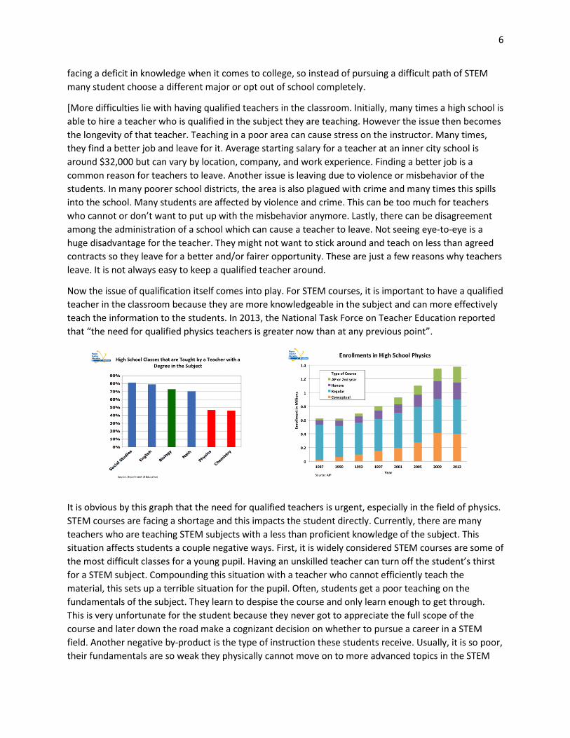
knowledge needed to succeed at the college level. As the first image depicts, many students are already
6
facing a deficit in knowledge when it comes to college, so instead of pursuing a difficult path of STEM
many student choose a different major or opt out of school completely.
[More difficulties lie with having qualified teachers in the classroom. Initially, many times a high school is
able to hire a teacher who is qualified in the subject they are teaching. However the issue then becomes
the longevity of that teacher. Teaching in a poor area can cause stress on the instructor. Many times,
they find a better job and leave for it. Average starting salary for a teacher at an inner city school is
around $32,000 but can vary by location, company, and work experience. Finding a better job is a
common reason for teachers to leave. Another issue is leaving due to violence or misbehavior of the
students. In many poorer school districts, the area is also plagued with crime and many times this spills
into the school. Many students are affected by violence and crime. This can be too much for teachers
who cannot or don’t want to put up with the misbehavior anymore. Lastly, there can be disagreement
among the administration of a school which can cause a teacher to leave. Not seeing eye-to-eye is a
huge disadvantage for the teacher. They might not want to stick around and teach on less than agreed
contracts so they leave for a better and/or fairer opportunity. These are just a few reasons why teachers
leave. It is not always easy to keep a qualified teacher around.
Now the issue of qualification itself comes into play. For STEM courses, it is important to have a qualified
teacher in the classroom because they are more knowledgeable in the subject and can more effectively
teach the information to the students. In 2013, the National Task Force on Teacher Education reported
that “the need for qualified physics teachers is greater now than at any previous point”.
It is obvious by this graph that the need for qualified teachers is urgent, especially in the field of physics.
STEM courses are facing a shortage and this impacts the student directly. Currently, there are many
teachers who are teaching STEM subjects with a less than proficient knowledge of the subject. This
situation affects students a couple negative ways. First, it is widely considered STEM courses are some of
the most difficult classes for a young pupil. Having an unskilled teacher can turn off the student’s thirst
for a STEM subject. Compounding this situation with a teacher who cannot efficiently teach the
material, this sets up a terrible situation for the pupil. Often, students get a poor teaching on the
fundamentals of the subject. They learn to despise the course and only learn enough to get through.
This is very unfortunate for the student because they never got to appreciate the full scope of the
course and later down the road make a cognizant decision on whether to pursue a career in a STEM
field. Another negative by-product is the type of instruction these students receive. Usually, it is so poor,
their fundamentals are so weak they physically cannot move on to more advanced topics in the STEM

7
field. Their weak background causes much difficulty in subsequent courses. This is a disaster for the
pupil. Since non-STEM majors involve little to no foundation building and can be picked up much easier,
these young student strive for those majors leaving the STEM field dry.
Unfortunately this situation isn’t always the teachers fault. Many times budget issues are a major cause
to these discrepancies. Poorer districts don’t have the resources to acquire a solid STEM teacher and if
they do, many times the teacher leaves within a few years, recreating the initial problem of a teacher
who isn’t qualified being forced to teach a STEM class with little knowledge. Sometimes the schools look
at the bare minimum and are just trying to fill the STEM course with a body and so don’t put much
emphasis on the quality or qualification of the instructor.
Getting a qualified teacher is only the beginning. The next step is to incite curiosity and intellectual
stimulation for young students, and this can be done by implementation of STEM projects in the
classroom. The goal of our project is to build a Stirling engine from basic materials. There are hundreds
of other simple experiments out there that are low-cost and highly effective to the student. Many
students are visual learners, and after reading about a STEM concept all week, nothing would be better
than creating a hands on lab where a student can utilize the knowledge they gained and watch it work
out before him.
Adding on to the numerous quantity of experiments ranging from easy to difficult, is also the knowledge
factor. There are experiments for every age and every topic. The beautiful aspect about applying STEM
to laboratories it that not much knowledge is needed. There are experiments for every learning level.
This creates an opportunity for teachers to build on past knowledge and projects. Things can always get
more complicated, but that is not necessarily the goal. As mentioned before, successful STEM projects
foster a yearning to learn more. When a student is inspired by an experimental topic, that’s when
progress can be made. Giving STEM majors a fair chance for a student to choose them is how the United
States can bring their numbers of engineers, biologists, chemists, physicists, and other STEM majors up.
The teacher plays an integral role through this entire process. By having time in their lesson plans for
these small and simple experiments, they can have a profound impact on the STEM growth of a student.
In contrast, just having a body to fill the role of a STEM teacher will usually yield no hands on
experiments for the students and they will have missed out on putting their knowledge to work.
Stressing the importance of cost, the experiments can be very simple ones. The goal in choosing an
effective experiment is the being a cost-efficient as possible. Many schools don’t have the budget for
lavish science labs. Using simple household objects, this won’t be an issues. By properly informing the
STEM about the cheap cost and low-labor of these experiments [By providing simple, low-cost STEM
projects], even the poorest classrooms in the United States can make room for an experiment or two.
The impacts of a STEM major go beyond the degree itself. Besides receiving a wealthy salary, the
opportunities created for a student and numerous and versatile. Many students who graduate with a
STEM major gain skills otherwise missed in other degree programs such as problem solving skills,
analytical skills, mathematical skills, technical skills, attention to detail, and systemic skills. These skills
make the STEM graduate a more marketable product. According to a 2007 study by Georgetown
University Professor B. Lindsey Lowell and Rutgers University Professor Hal Salzman, only a third of
science and engineering graduate actually take jobs in the science and tech fields. This is where the
versatility comes into play. STEM majors who stay in their respective field after graduation will earn an

8
average annual salary of $78,550 in 2009. However, STEM graduates who take their services to a
managerial or professional field started off with an average annual salary of over $102,000.
A STEM degree is also transferrable. Physics in United States is the exact same as that in the United
Kingdom, as well as Spain. The graduate will have the freedom to know wherever place he finally settles
into, his expertise will hold its value and his services can be used.
In closing, creating greater opportunity for a career in a STEM major can bring many young children in
inner-city schools the chance to make a real difference for their own family and their community. Their
skills gained in the classroom by effective presentation and teaching of STEM courses supplemented by
energizing experiments, can create inspiration for young student to pursue a STEM career. The benefits
are widespread and the graduate can better find a job he will enjoy with the skills he’s learned by being
s STEM graduate.

9
Stirling Engine Proposal
Our primary proposal is to use a β-Stirling (air) engine to develop mechanical work. Our working device
will be a gear. In this manner the gear may be attached to wheels, and the engine may be mounted on a
chassis. This will make a simple but educational miniature that may be constructed from things that can
be found around the house. This is the main device, but supplemental devices using the Stirling engine
will be pursued in other pieces by our group members. We also hope to develop devices employing
usage of the ‘alpha’ and gamma’ engines. The purpose of constructing such devices is to implement it
into some sort of extracurricular program for underprivileged youth. The students can construct the
device in groups, thus introducing a cooperative element. When the students are finished, the device
will generate work, driving a wheel, and teach the students about the principles behind it in the process.
We also hope to highlight the interesting and colorful history of the device (outlined below). Moreover,
the results of the higher-level math that govern the engine’s mechanics reduce to a set of simple
equations (also outlined below) which can be explained at a low-level to the students by an instructor
with physics or chemistry training. It is our hope that such a project would spur interest in the
engineering discipline, and inspire kids to continue with their education. Additional advantages to such a
program include: (1) demonstrating to children that engineering is not difficult, and can be engaged in
recreationally & (2) introducing the youth to creative and unique ideas for energy sources.
History of the Stirling Engine1
What exactly is a Stirling Engine? To understand what a Stirling engine is it is best to put it into historical
context. At the dawn of the Industrial Revolution the British steam engine industry was developing into
a powerful monolith. In the French engineer and physicist Sadi Carnot’s book he cited the steam engine
as the primary source of power of the British. He claimed that this was true in virtue of the fact that the
British used steam engines in every walk of life. Presumably, this British dominance of the industry
bothered Carnot, and so he set out in making the French steam engine industry competitive. The
question that was being asked, which Carnot’s piece sought to answer, was how to improve engine
efficiency. People tried all sorts of things in attempts to improve efficiency. One common choice was to
experiment with working fluids. These projects, however, were frequently unsuccessful. In one notable
example off the coast of Marseilles, France, some scientists endeavored to use ether as the working
fluid for a steam ship. The thought, roughly, was that the increased volatility of ether, as composed to
other working fluids, would improve efficiency. Not surprisingly, this experiment ended in an explosive
fashion. One scientist, William Rankine, wrote a report on the subject indicating that if the scientists had
been aware of Carnot’s work, they would have realized that changing the working fluid was not the
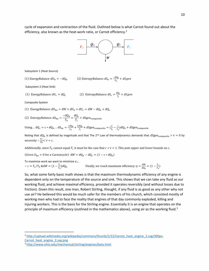
answer to improving efficiency. Carnot’s solution was to reduce the engine down to 3 parts; a heat
source, heat sink, and working fluid. The heat source is essentially a high temperature area, and the heat
sink is a low temperature area. These two areas are in contact across a working fluid, either liquid or
gas. As heat flows from the hot source to the cool sink to try and achieve equilibrium, this causes the
working fluid to expand. When a piston is placed between the hot and cold sides, work is generated by a
1 All of the historical information was done on memory. Some of it was taken from a lecture by Jos Uffink on the history of Thermodynamics. The other information was taken from a lecture by Michael Paulitis on the history of Thermodynamics.
10
cycle of expansion and contraction of the fluid. Outlined below is what Carnot found out about the
efficiency, also known as the heat-work ratio, or Carnot efficiency.2
Subsystem 1 (Heat Source)
(1) EnergyBalance: dUℎ = −dQℎ (2) EntropyBalance: dSℎ =−dQℎ
𝑇ℎ+ 𝑑𝑆𝑔𝑒𝑛
Subsystem 2 (Heat Sink)
(1) EnergyBalance: dU𝑐 = dQ𝑐 (2) EntropyBalance: dS𝑐 =dQ𝑐
𝑇𝑐+ 𝑑𝑆𝑔𝑒𝑛
Composite System
(1) EnergyBalance: dUhe = dW + dUℎ + dU𝑐 = dW − dQℎ + dQ𝑐
(2) EntropyBalance: dShe =−dQℎ
𝑇ℎ+
dQ𝑐
𝑇𝑐+ dSgencomposite
Using. . . dQ𝑐 = c ∗ dQℎ. . . dShe =−dQℎ
𝑇ℎ+
λdQℎ
𝑇𝑐+ dSgencomposite = (
𝐶
𝑇𝑐−
1
𝑇ℎ)dQℎ + dSgencomposite
Noting that dQℎ is defined by magnitude and that The 2nd Law of thermodynamics demands that 𝑑Sgencomposite > ∨ = 0 by
necessity ∴ 𝑇𝑐
Th< ∨ = c.
Additionally, since 𝑇ℎ cannot equal 𝑇𝑐 it must be the case that 𝑐 > ∨ = 1. This puts upper and lower bounds on 𝑐.
(Given 𝑈he = 0 for 𝑎 Carnotcycle) dW = dQℎ − dQ𝑐 = (1 − c ∗ dQℎ)
To maximize work we want to minimize 𝒄…
∴ 𝑐 = 𝑇𝑐 𝑇ℎ⁄ &dW = (1 −𝑇𝑐
𝑇ℎ)dQℎ Finally, we reach maximum efficiency: 𝜂 =
dW
dQℎ= (1 −
𝑇𝑐
𝑇ℎ)
So, what some fairly basic math shows is that the maximum thermodynamic efficiency of any engine is
dependent only on the temperature of the source and sink. This shows that we can take any fluid as our
working fluid, and achieve maximal efficiency, provided it operates reversibly (and without losses due to
friction). Given this result, one man, Robert Stirling, thought, if any fluid is as good as any other why not
use air? He believed this would be much safer for the members of his church, which consisted mostly of
working men who had to face the reality that engines of that day commonly exploded, killing and
injuring workers. This is the basis for the Stirling engine. Essentially it is an engine that operates on the
principle of maximum efficiency (outlined in the mathematics above), using air as the working fluid.3
2 http://upload.wikimedia.org/wikipedia/commons/thumb/2/22/Carnot_heat_engine_2.svg/300px-Carnot_heat_engine_2.svg.png 3 http://www.ohio.edu/mechanical/stirling/engines/beta.html

11
4
There are a few pieces to the engine that we haven’t seen yet, notably the displacer and the
regenerator. Regarding the displacer - This piece can be nearly anything of the appropriate size, as it’s
only purpose, in some sense, is to move through the air. The regenerator, on the other hand will store
heat from the air, as they are in thermal contact. We will see more on these concepts later. So, The
Stirling engine operates on the Stirling cycle. In effect, this heating and cooling of the permanent
gaseous working substance is what drives the mechanical work. For instance, in the beta-Stirling engine,
we have some sort of tube. Inside this tube, the displacer is mounted. On one side of the displacer is the
heat source – on the other side is some lower temperature area, or cooling device (ex: cooling fins). Also
in the tube, mounted atop the working fluid is the piston. The piston is connected to the crankshaft,
which is connected to some sort of device that generates angular momentum. The displacer is generally
attached about ninety degrees away from the piston. This set up allows the displacer to shunt air back
and forth around it so that the air is alternately heated and cooled. This cycle of heating and cooling the
permanently gaseous working fluid is what generates the mechanical work. Notice now that, given our
setup, nothing stops us from choosing our mechanical work device to be a gear, and attaching wheels. A
very simple device, in this spirit, such as the one shown to the left could be mounted on a chassis.
4 http://www.ohio.edu/mechanical/stirling/engines/beta.html
12
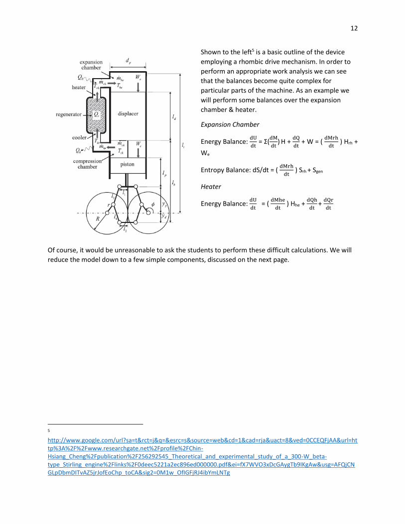
Shown to the left5 is a basic outline of the device
employing a rhombic drive mechanism. In order to
perform an appropriate work analysis we can see
that the balances become quite complex for
particular parts of the machine. As an example we
will perform some balances over the expansion
chamber & heater.
Expansion Chamber
Energy Balance: dU
dt = Σ(
dM
dt) H +
dQ
dt + W = (
dMrh
dt ) Hrh +
We
Entropy Balance: dS/dt = ( dMrh
dt ) Srh + Sgen
Heater
Energy Balance: dU
dt = (
dMhe
dt ) Hhe +
dQh
dt +
dQr
dt
Of course, it would be unreasonable to ask the students to perform these difficult calculations. We will
reduce the model down to a few simple components, discussed on the next page.
5 http://www.google.com/url?sa=t&rct=j&q=&esrc=s&source=web&cd=1&cad=rja&uact=8&ved=0CCEQFjAA&url=http%3A%2F%2Fwww.researchgate.net%2Fprofile%2FChin-Hsiang_Cheng%2Fpublication%2F256292545_Theoretical_and_experimental_study_of_a_300-W_beta-type_Stirling_engine%2Flinks%2F0deec5221a2ec896ed000000.pdf&ei=fX7WVO3xDcGAygTb9IKgAw&usg=AFQjCNGLpDbmDITvAZ5jrJofEoChp_toCA&sig2=0M1w_OfIGFjRJ4ibYmLNTg
13
(1) The ideal engine, which generates work. The way the work will be generated will be clear for the
students to see. To appropriately deal with this issue we will reduce things down to a very simple
balance on the working fluid:
The equation is dU
dt =
dQ
dt + W which simply says that the change in the internal energy is equal to
the change in heat plus work. Introducing the concept of work also gives us a chance to introduce
power, which is simply work/time.
(2) Two mechanical working devices – one the displacer and the other the angular momentum
device. We can treat these as simple mechanical systems. The displacer can be treated as a device
which generates kinetic energy via linear momentum (MV) the other via angular momentum (L =
I ω).
KEdisplacer = ½ M*V^2 REgear = .5 I* ω^2 : ω [radians/second]
∴ Wmechanical = ½ (MV^2 + Iω^2)
These concepts should be sufficient to explain the device in an educational manner. One can see that
the differentials can be naturally worked out of the above computations.
Design Considerations
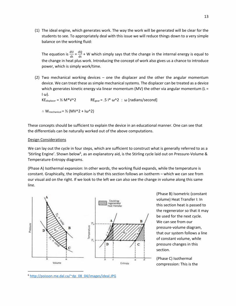
We can lay out the cycle in four steps, which are sufficient to construct what is generally referred to as a
‘Stirling Engine’. Shown below6, as an explanatory aid, is the Stirling cycle laid out on Pressure-Volume &
Temperature-Entropy diagrams.
(Phase A) Isothermal expansion: In other words, the working fluid expands, while the temperature is
constant. Graphically, the implication is that this section follows an isotherm – which we can see from
our visual aid on the right. If we look to the left we can also see the change in volume along this same
line.
(Phase B) Isometric (constant
volume) Heat Transfer I: In
this section heat is passed to
the regenerator so that it may
be used for the next cycle.
We can see from our
pressure-volume diagram,
that our system follows a line
of constant volume, while
pressure changes in this
section.
(Phase C) Isothermal
compression: This is the
6 http://poisson.me.dal.ca/~dp_08_04/images/ideal.JPG
14
similar to phase A, except that the gas is cooled, and consequently, contracts. Similarly to A, this process
follows an isotherm.
(Phase D) Isometric Heat Transfer II: In this section heat is transferred from the regenerator to the
working fluid.
The success of our engine depends on us developing a device which has stages that closely correspond
to those outlined above and abiding by estimations done for initial power7.
Different Types of Stirling Engines
There are three basic layouts of Stirling engines; alpha, beta, and gamma. All three types use the same
basic principles to produce work (temperature differential drives adiabatic fluid compression and
expansion), but mechanically are structured differently.
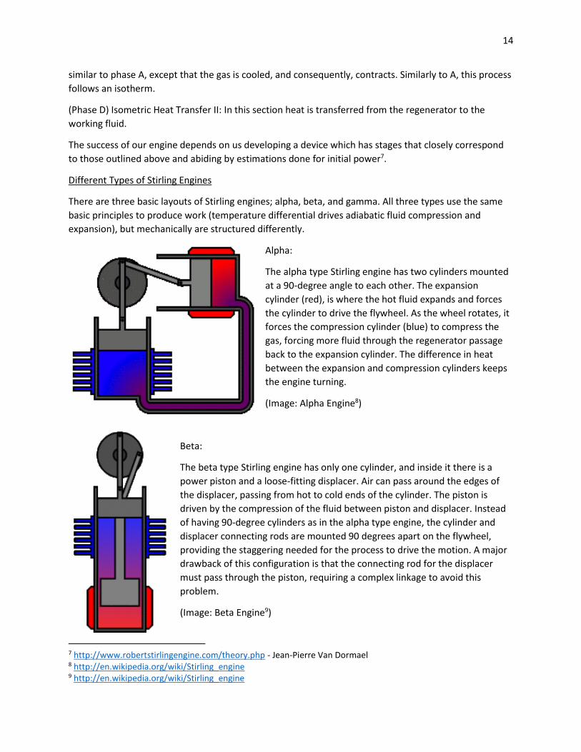
Alpha:
The alpha type Stirling engine has two cylinders mounted
at a 90-degree angle to each other. The expansion
cylinder (red), is where the hot fluid expands and forces
the cylinder to drive the flywheel. As the wheel rotates, it
forces the compression cylinder (blue) to compress the
gas, forcing more fluid through the regenerator passage
back to the expansion cylinder. The difference in heat
between the expansion and compression cylinders keeps
the engine turning.
(Image: Alpha Engine8)
Beta:
The beta type Stirling engine has only one cylinder, and inside it there is a
power piston and a loose-fitting displacer. Air can pass around the edges of
the displacer, passing from hot to cold ends of the cylinder. The piston is
driven by the compression of the fluid between piston and displacer. Instead
of having 90-degree cylinders as in the alpha type engine, the cylinder and
displacer connecting rods are mounted 90 degrees apart on the flywheel,
providing the staggering needed for the process to drive the motion. A major
drawback of this configuration is that the connecting rod for the displacer
must pass through the piston, requiring a complex linkage to avoid this
problem.
(Image: Beta Engine9)
7 http://www.robertstirlingengine.com/theory.php - Jean-Pierre Van Dormael 8 http://en.wikipedia.org/wiki/Stirling_engine 9 http://en.wikipedia.org/wiki/Stirling_engine

15
Gamma:
The gamma type Stirling engine is essentially the same cycle as the beta
type, but the displacer piston is mounted in a separate cylinder to the
power piston. This avoids the dilemma caused by the displacer linkage
passing through the piston as in the basic beta type.
The gamma type Stirling engine can run on the smallest temperature
differentials, but the drawback is that it also produces low specific
power. This means that while gamma engines can be made to run on
nothing but the heat from a person’s hand, they will be difficult to
design in a way that will provide enough power to run a small car like we
are attempting to do.
(Image: Gamma Engine10)
How to Build a Simple Stirling Engine
Our goal is to come up with some simple designs for Stirling engines that can be made with household
items that can be procured for cheap. Our challenge will be to come up with a few designs that can be
easily and quickly built, and will also provide a significant amount of power to potentially move a small
car. A quick search on YouTube or Google turns up many simple designs that people have created using
everyday items.
- Cylinders can be made from soda cans or coffee cans.
- Flywheels can be made using paint can lids or CD’s.
- Wire, bits of balsa wood, and small metal rods can become the axles and connecting rods.
- A displacer can be made out of a small section of balloon rubber, stretched over the end of
the cylinder.
- Pistons can be made out of cardboard, foam, cork, or plastic.
- A votive candle can serve as the heat source
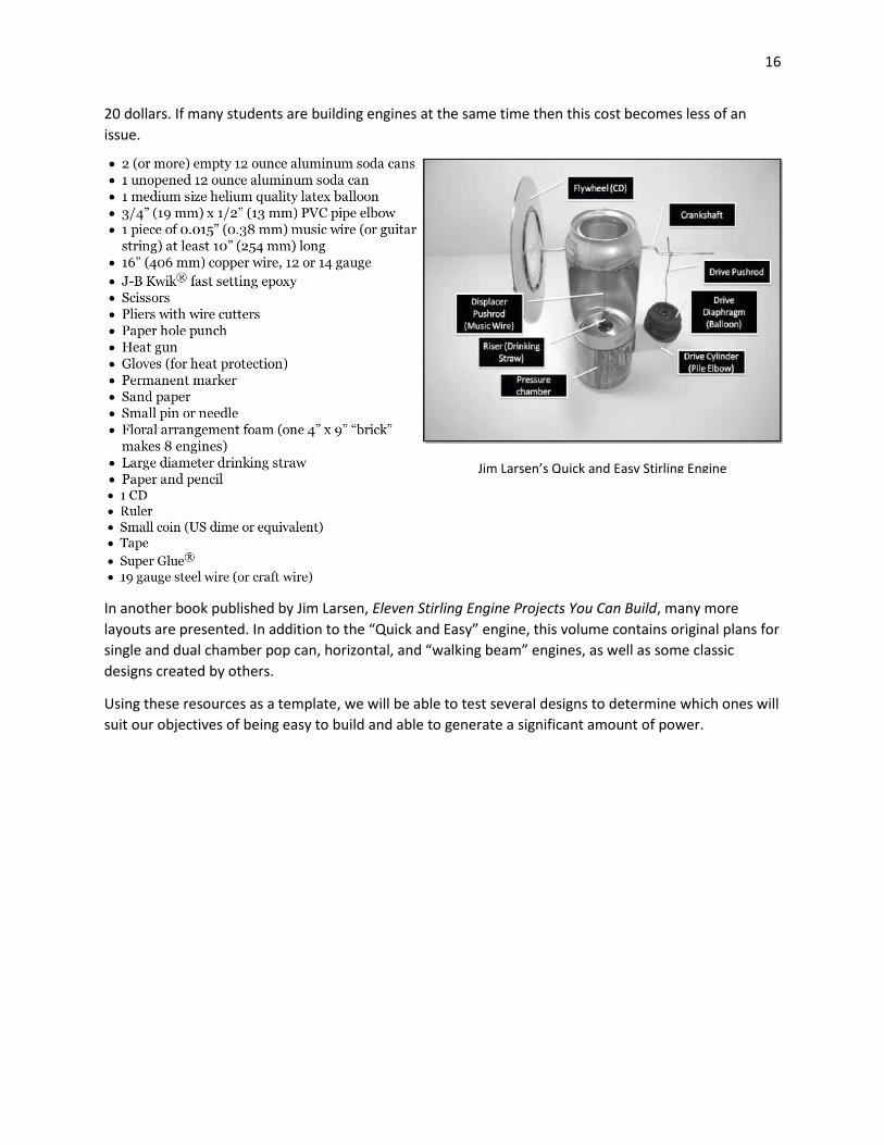
In one manual, entitled Quick and Easy Stirling Engine11, the author details a set of plans for creating a
homemade engine using the basic materials listed below in “as little as 3 hours.”
His design proves that it is not difficult to make an engine that will run smoothly and efficiently in a short
amount of time. A piece of foam serves as a displacer, and a cut-up balloon becomes a drive diaphragm.
The most difficult part of this design is the use of a heat gun to melt the end of the PVC elbow so as to
conform it to sit flush against the curved can. This is an ingenious solution to a difficult design problem,
but it also makes the project slightly more dangerous. The heat gun could make the design slightly more
expensive as well if there isn’t one around to use already. A low-end model on Amazon runs around 15-
10 http://www.mpoweruk.com/images/stirlingG.gif 11 Larsen, Jim R. Quick and Easy Stirling Engine. Olympia, WA: Jim R. Larsen, 2012. Print.
16
20 dollars. If many students are building engines at the same time then this cost becomes less of an
issue.
In another book published by Jim Larsen, Eleven Stirling Engine Projects You Can Build, many more
layouts are presented. In addition to the “Quick and Easy” engine, this volume contains original plans for
single and dual chamber pop can, horizontal, and “walking beam” engines, as well as some classic
designs created by others.
Using these resources as a template, we will be able to test several designs to determine which ones will
suit our objectives of being easy to build and able to generate a significant amount of power.
Jim Larsen’s Quick and Easy Stirling Engine

17
Design Specifications
Here are some rough sketches12 of what each engine will look like. The students can determine which
engine best suits them mainly by setup (beta being a lay-down style, where alpha and gamma pump up
and down). That will cause them to weigh their options based on different specifications of the pumps,
but ultimately it will be up to them to specify that their design specs will be within the boundaries of
their project. Also, demonstrated here is the impact of the household objects within the design. In two
cases just a can creates the cylinder for the piston, or the balloon can be used to form the rubber
diaphragm. Balsa wood, which is cheap and light, will be used to form all rigid bodies because of its ease
of application (easy to cut and connect).
12 All drawings done by hand, as an example of using household items to create the Stirling Engine

18
Further Design Possibilities
This design option will discuss using a Stirling engine to provide the locomotion for a small car. A low
cost, effective structural material to construct the car is K’NEX. The exact size of the built Stirling engine
is yet to be determined, but the general concepts will remain the same. The idea is to use the flywheel
of the Stirling engine as either a gear or a chain motor (similar to the rig pictured in figure A) to be
connected to the rear axle of the car (similar to figure B).
Figure A: chain motor assembly Figure B: rear axle example
The K’NEX will then be assembled into a sturdy frame with wheels to act as a casing for the engine. A
potential hazard presents itself in the heat source of the engine. The heat source is capable of
producing heats of (up to) 180 degrees Fahrenheit. Due to this extreme temperature of the heat source,
the concern of plastic melting becomes a major issue. This will require some low level heat shielding.
This shielding could easily be provided with insulating tape readily available in stores. One such example
is “Design Engineering Reflect-A-GOLD” Heat Reflective Tape, which is able to handle continual
temperatures of up to 850°F which will more than surpass our needs for heat shielding at a low cost.
At its most basic level (accounting only for overcoming friction forces to turn the wheel), 0.044 newton-
meters are required to rotate the back axle to provide locomotion. This estimation is extremely limited
due to the broad assumption the cars total weight as a pound and a half. The built engine will give a
much more accurate indication of the requirements.
After assembly of the Stirling engine is complete, and the car is sized to fit the engine, testing and
elaborations of the design can be investigated. Operating under the assumption that the Stirling engine
provides enough power to move the car, tests to see how long and fast the locomotion can be sustained
will lend answers to further applications. One possible investigation could be to skew the wheels at an
angle so that the free driving car would travel a radius instead of dealing with the limited confines of a
room. This option would allow the engine and car to run to exhaustion.
19
Alternative Heat Source
For the sake of size and efficiency we could provide a heat source out of a battery and resistive wire. The
heat produced will initiate the cycle of the heat Stirling Engine that operates by cyclic compression and
expansion of air or other gases at different temperature. There is a net conversion of heat energy to
mechanical work.
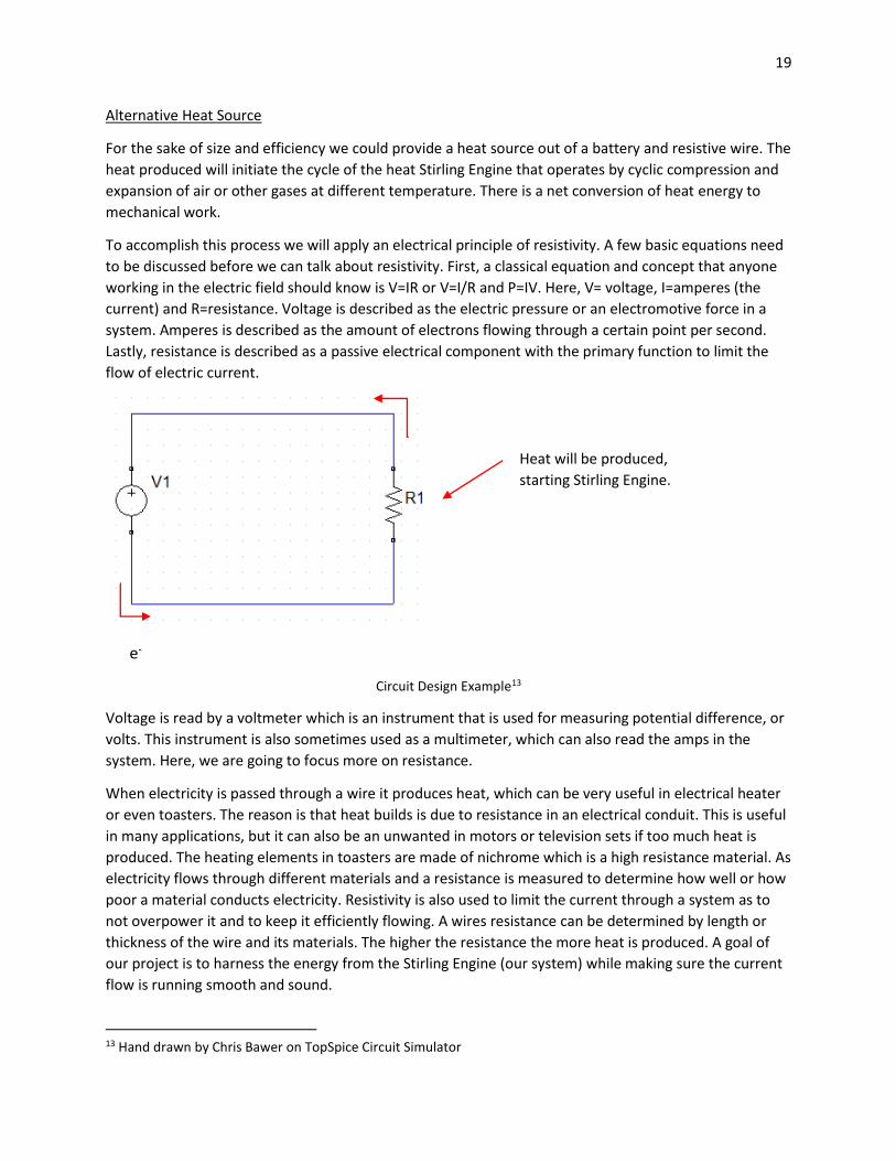
To accomplish this process we will apply an electrical principle of resistivity. A few basic equations need
to be discussed before we can talk about resistivity. First, a classical equation and concept that anyone
working in the electric field should know is V=IR or V=I/R and P=IV. Here, V= voltage, I=amperes (the
current) and R=resistance. Voltage is described as the electric pressure or an electromotive force in a
system. Amperes is described as the amount of electrons flowing through a certain point per second.
Lastly, resistance is described as a passive electrical component with the primary function to limit the
flow of electric current.
e-
Circuit Design Example13
Voltage is read by a voltmeter which is an instrument that is used for measuring potential difference, or
volts. This instrument is also sometimes used as a multimeter, which can also read the amps in the
system. Here, we are going to focus more on resistance.
When electricity is passed through a wire it produces heat, which can be very useful in electrical heater
or even toasters. The reason is that heat builds is due to resistance in an electrical conduit. This is useful
in many applications, but it can also be an unwanted in motors or television sets if too much heat is
produced. The heating elements in toasters are made of nichrome which is a high resistance material. As
electricity flows through different materials and a resistance is measured to determine how well or how
poor a material conducts electricity. Resistivity is also used to limit the current through a system as to
not overpower it and to keep it efficiently flowing. A wires resistance can be determined by length or
thickness of the wire and its materials. The higher the resistance the more heat is produced. A goal of
our project is to harness the energy from the Stirling Engine (our system) while making sure the current
flow is running smooth and sound.
13 Hand drawn by Chris Bawer on TopSpice Circuit Simulator
Heat will be produced,
starting Stirling Engine.

20
The heating elements in toasters are made of nichrome which is a high resistance material. As electricity
flows through different materials and a resistance is measured to determine how well or how poor a
material conducts electricity. A wires resistance can be determined by length or thickness of the wire
and its materials. The higher the resistance the more heat is produced.
In our set up electricity will flow from the negative terminal of the battery and this has an excess
amount of electrons, while the positive terminal of the battery lacks electrons. This process can be
completed by attaching a battery in series with a high resistive wire. The wire will then produce residual
heat because of the movement of electrons through the circuit creating the heat desired for our Stirling
Engine. However there is a time component required to for this process to take effect. Depending on the
resistance of the wire the time component may vary. Yet to produce enough heat to begin our system it
will only take a five minutes to reach an optimal temperature for operation. The heat required for this
device to run at its peak would be to have a change in temperature of 15°F. So to acquire this difference
we can add dry ice to our secondary side creating a large change in temperature. With a larger change in
temperature the engine will produce more power.
Instructables Stirling Engine Example14
Refer to the Appendix for calculations that shown we have two different means to produce heat: three
AA batteries or two 9V batteries. The calculations provide us with temperature of about 300 and 108
degrees Fahrenheit respectively for each case. Now adding dry ice to secondary side to increase our
delta will provide enough work to start engine and allow it to travel. However we must take into
consideration the longevity of the battery which is substantially affected by this circuit. The average
14 http://www.instructables.com/id/Tin-Can-Stirling-Engine/

21
shelf life for a 9V energizer battery is 5 years whereas the average shelf life for a single AA energizer
battery is 10 years. Now if we are to place each battery in the circuit, the life of the battery is will
degrade to a less than 50% cycle. A normal functioning battery ranging from 500 to 800 (charge –
discharges) cycles. Yet with our addition of dry ice to the secondary side, it will allow the heat within the
primary side to power the engine even after the battery dies out.
In final, we should take into consideration minor problem that we may be faced with like too large of a
delta. In this two chamber system it allows us to add a cooling agent to create a larger displacement of
temperature, which will lead to a greater work output. This can modify but slowly adding in a cooling
agent to a desired work output. As the batteries fade we can add more cooling agent to increase the
delta. This being that because the two chambers are separated the displacer has to pass from the
cooling chamber to the heating chamber while having the heating chamber to not lose a significant
about of heat. With this in mind we can say with a certain degree of certainty that the heating chamber
even after the batteries fade will still have a higher temperature than the cooling chamber and will hold
that temperature for significant length of time. By adding more cooling agent it will re-affirm that the
change in temperature will stay above the noted 15°F.
Our initial idea of using an electrical heat source was highly improbably because of the lack of heat produced by our electrical heat source. However we overcame this process by implementing a candle which burns at average temperature of 1400 degrees Celsius. This large heat source will provide enough temperature change to create a larger enough displace to start and create a continuous engine cycle.

22
Evaluation
Environmental and Economic Impact
A homemade Stirling engine, like the one our group would want to build, could be easily made using
parts found in one’s home, some small lumber, and small copper tubing. The exact design can vary, but
the most common include some sort of large cylinder with a displacer and a spinning wheel connecting
to one or more pistons attached to the main cylinder. The main cylinder can be made from several soup
cans stacked from end to end, attached together with the tops and bottoms cut out. If a piston is used,
a hole will need to be cut in the side of the can and some sort of shaft and piston will need to be
attached. These will most likely have to be bought as it will be difficult to find something to be sturdy
enough around the house to function as this. The lumber would be attached to both sides of the main
cylinder to keep it elevated and steady. A spinning disk will need to be attached to both the suspended
weight (displacer) in the cylinder and the piston. This disk could be machined from metal or is could be
as simple as a CD weighted with pennies. The connection rods will need to be made of some sort of
metal so as they do not bend easily. This could easily be satisfied with a coat hanger or some other
miscellaneous metal wire that could be purchased. The weight could be as simple as a tuna can. The
piston could be a cork with a hook attached and the tube around it purchased copper piping. The heat
source would need to be bought. A simple tea candle would suffice, or with some of the variations even
hot liquid works. This would be the only component that would need to be replaced over the lifetime of
the machine.
Most of the items mentioned above would have already served their original purpose and be reused for
this project. This would include the cans, the cork, the coat hanger, and the CD. Some would have to be
bought such as the candle(s), the copper, and the plywood. Once this project is over, the engine could
be disassembled and recycled. The cans could be recycled by curbside pickup. The CD would have to be
mailed to special recycling centers in order to be recycled. The wood could be burned in a stove for fuel
or taken to special recycling centers. The coat hanger, metal wire, or metal flywheel would have to be
taken to a special recycling center. The exhausted candle would have to be thrown out. A typical candle
takes about ten years to decompose, but a burnt out candle would most likely take less time. A typical
tea candle has a metal container that could be recycled. Not all recycling centers take CDs, metal, or
wood. This means that in some cases these materials would have to be thrown out with the trash. Ply
wood takes about 3-5 years to decompose, aluminum cans take about 200-500 years, CDs and other
plastics take several millions years, and metal doesn’t decompose.
A candle creates heat and light by combustion. This is the combination of C25H52 and O2 to create a
gaseous H2O and CO2. CO2 and vaporous H2O are common greenhouse gases. According to Physical
Insights on wordpress.com, burning a candle that produces 40W of energy creates about 10.69g of CO2
per candle per hour. According to the EPA, transportation in America creates about 828840266g of CO2
each year. This accounts for only 28% of the CO2 that is created by America. Relative to the total
amount of greenhouse gases created by America, burning one or even several candles creates negligible
impact to global warming. I’ll assume the same goes for vaporous H20. Industrial size Stirling engines
also have the problem of residue heat, but our small scale project uses outside air as the cold
temperature and so this isn’t an issue.
Most, if not all of the materials of this project, could be found from scrounging around one’s house.
However, this may not always be possible as all households are different. In the case of not having

23
enough materials, it might be necessary to buy some of them. As such, the cost of everything must be
considered. We have provided below the cost of materials.
Bill of Materials
Soup Can - $0.99/ free
Pop Can - $0.99/ free
Compact Disk - 30 pack/ $10.00
Hand full of Rubber Bands - package of 2000/ $7.00
Balsa Wood $8.00 max from Hobby Lobby
Candle - 100 pack from IKEA/ $4.00
Balloon - 50 pack from Amazon/ $13.00
9-Volt Battery - 4/ $12 from Wal-Mart
Circuit Wire - 6 ft. for $6.00 from Amazon
Alligator Clips - $3.49 from RadioShack
Again, to emphasize, most of these materials could be just picked up around the house. Almost every
student will have access to leftover cans, rubber bands, old CD’s, or candles. In the interest of time and
efficiency, it might make sense for the teacher (or program leader) to have most of the rest of the
objects purchased, in bulk, ahead of time.
Cost analysis
In our team we are working with Stirling Engine project that requires buying some
components before building it up. Those components are not are very expensive to buy them and can
be collected with few dollars. Hence, to build the project the team is investing about 25 dollars to
build up its project. Furthermore, since most of the equipment are centered on the idea of “mechanical
work” they are easily accessible on daily basis. Some of project equipment that we’ve dealt with cans,
and candles. The Stirling engine is a heat engine that operates by cyclic compression and expansion
of are at different temperatures. The purpose of this project is to provide the equipment of this
classic engine, and present it to city schools as part of the STEM curriculum. It’s quite obvious that this
engine is very complex and requires specific equipment in order for it to function. With that said, all
members of the group are gathering some together so that we can buy the items we need for the
presentation, and so that we can generate heat source from the engine.
After gathering some information regarding the function and structure of the Stirling
engine, we came to a conclusion that we needed to purchase ten important items. The items on our
list includes, cardboard, epoxy, balloons, hot glue gun, hot glue, steel wool, rubber bands, paper
clips, bolt/washer, and 50 candles. Providing these important items requires a lot of labor and cost.

24
Thus, every member of the group was asked to give some portion of money, so that we it’s evenly
balanced throughout the group. The price of these equipment requires a total of $25 dollars. For
independent item of cost please refer to the attachment table.
After coming up with the list of items and the amount of cost needed to buy the items, we
concluded that it’s important include the labor needed to get the item to a specific person and place.
Thus, our group members are going to decide who’s going to buy the items, from where and when
exactly. As you can see our plan is very organized and effective. The purpose of doing this is to make
sure that everyone in the group is participating, and most importantly to make sure that the items
needed are provided on healthy conditions, so that we can demonstrate a remarkable presentation
to city schools, and we hope that the schools will learn something regarding the Stirling engine
and its function. The last column of the Table 1 is interesting because it shows that the price tag is
decreasing as the quantity gets larger. The final cost will go down due to lower price tags for each
purchase.
Item
Cost ( Dollars)
Larger Quantities
Cardboard
------
-----
Epoxy
$ 4.00
Lower than each unit price
Balloons
$ 1.00
Lower than each unit price
Hot Glue Gun
$ 7.00
Lower than each unit price
Hot Glue
$ 3.00
Lower than each unit price
Steel Wool
$ 3.00
Lower each unit price
Paper Clips
-----
------
Bolt / Washer
$ 1.15
Lower than each unit price
50 Candles
$ 2.50
Lower than each unit price
Total
$ 25.00
Decreases by some percentage
Table 1: Cost Breakdowns
25
Implementation
Stirling Engine Construction & Operation
Parts List
In the last piece we outlined a few key parts that typically compose a Stirling engine. These include the
displacer, regenerator, the piston, the heat source, sink and so forth. Also, briefly outlined is the
function of these pieces in the context of the Stirling engine. A brief disclaimer is in order regarding
these pieces; we will be regarding these pieces as conceptual objects rather than the simple predicates
to which they typically refer. In other words, we will be using these pieces as terms of art.
Key Parts:
(1) Power Piston
Description: The power piston is the piece which outputs mechanical work. It is typically motivated by
the expansion and compression of the gas in the compression space. The expansion of the gas results in
linear momentum in the crankshaft which evolves angular momentum on the flywheel. Note that the
power piston is distinct from the displacer which serves a very different purpose.
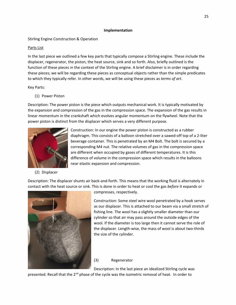
Construction: In our engine the power piston is constructed as a rubber
diaphragm. This consists of a balloon stretched over a sawed-off top of a 2-liter
beverage container. This is penetrated by an M4 Bolt. The bolt is secured by a
corresponding M4 nut. The relative volumes of gas in the compression space
are different when occupied by gases of different temperatures. It is this
difference of volume in the compression space which results in the balloons
near elastic expansion and compression.
(2) Displacer
Description: The displacer shunts air back-and-forth. This means that the working fluid is alternately in
contact with the heat source or sink. This is done in order to heat or cool the gas before it expands or
compresses, respectively.
Construction: Some steel wire wool penetrated by a hook serves
as our displacer. This is attached to our beam via a small stretch of
fishing line. The wool has a slightly smaller diameter than our
cylinder so that air may pass around the outside edges of the
wool. If the diameter is too large then it cannot serve the role of
the displacer. Length-wise, the mass of wool is about two-thirds
the size of the cylinder.
(3) Regenerator
Description: In the last piece an idealized Stirling cycle was
presented. Recall that the 2nd phase of the cycle was the isometric removal of heat. In order to
26
accomplish this, the gas is put in thermal contact with the regenerator, resulting in the transference of
heat. This results in cooling of the gas.
Construction: In our setup the displacer doubles as a regenerator. The steel wool & the air in its void
space heats up. This heat is later transferred to the gas.
(4) Heat Source
Description: The heat source does as its name implies. It provides heat input to the gas, which results in
the temperature rise. This is important because higher temperature gas occupies an increased volume
as compared to lower temperature gas.
Construction: A simple candle serves as the heat source. We have built a small aluminum housing unit &
platform to hold the candle. Truncated sections of a beverage canister serve as the two aforementioned
pieces.
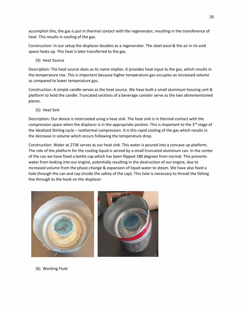
(5) Heat Sink
Description: Our device is intercooled using a heat sink. The heat sink is in thermal contact with the
compression space when the displacer is in the appropriate positon. This is important to the 3rd stage of
the idealized Stirling cycle – isothermal compression. It is this rapid cooling of the gas which results in
the decrease in volume which occurs following the temperature drop.
Construction: Water at 273K serves as our heat sink. This water is poured into a concave up platform.
The role of the platform for the cooling liquid is served by a small truncated aluminum can. In the center
of the can we have fixed a bottle cap which has been flipped 180 degrees from normal. This prevents
water from leaking into our engine, potentially resulting in the destruction of our engine, due to
increased volume from the phase-change & expansion of liquid water to steam. We have also fixed a
hole through the can and cap (inside the safety of the cap). This hole is necessary to thread the fishing
line through to the hook on the displacer.
(6) Working Fluid

27
Description: The working fluid is the substance which performs the mechanical work. It is the expansion
of the fluid which results in this work.
Construction: The working fluid of a Stirling engine is air. True to this description, it is the air in our
cylinder which performs the work in the expansion & compression space.
Remaining Parts:
What remains are not key, conceptually, to the engine. They are
important to function, however.
(7) Cylinder
Our cylinder was constructed from a truncated aluminum beverage
can. The top of the bottle was removed & sanded down. Following
this another aluminum beverage can was inserted so that the
aluminum keeps its shape. This can was later removed. The final
cylinder construction comes from the heat sink platform which is
inserted into the top of the can, sealing our cylinder.
(8) Crankshaft
Bent wire attached to a straight stretch of wire serves as a
crankshaft. Both ends of the first piece of metal are bent to
accommodate the M4 bolt & the second piece of wire. The second
wire is bent on both ends as well; this is to accommodate the beam
and the wheel itself.
(9) Beam
The beam is constructed from corrugated cardboard. The beam
must be perfectly level so that the power piston and displacer are 90
degrees out of phase

28
i
(10) Flywheel
The flywheel which evolves angular momentum is constructed from corrugated
cardboard. Some claims are made that the cardboard construction is good.
Some say that the cardboard has a high inertia for a low weight. I am skeptical
of this claim, but it is interesting enough to mention.
Sterling Engine Operation
In this section I will discuss the operation of our particular permutation on the Γ-Sterling engine. The
engine’s operation will be broken up based on the phases of the idealized Sterling cycle. The phases will
be shifted, so that A, B, C & D will not match the previous paper. This is done to better reflect the
engine’s operation. The images reflect our actual engine’s operation & construction.
Detailed on the following page is a diagram of the idealized operation of our constructed engine.

29
Phase A: Isometric Heat Addition

30
In the first stage, the working fluid (air) and
the heat source are allowed to thermally
equilibrate. Here our heat source is a candle. It
is housed inside the lower unit, where it is
exposed to the air. This is labeled TH on my
diagram. The provided temperature applies to
the gas in the space below the displacer. I very
much doubt that it gets quite this hot, since
the melting temperature of aluminum is just
shy of 950K. There will, however, be a
considerable increase in temperature of the
air in this space. We can also see that the gas
trapped in the compression space is cooled,
indicated by ‘Cg’. This cooled gas takes up a
much smaller volume as compare to heated
gas.
Phase B: Isothermal Expansion
In this stage the steel wool displacer is moved by the
continuously rotating flywheel. The net result of this is that
the rapidly heated gas now occupies the compression space.
The gas now expands at a (roughly) constant temperature.
Since the hot gas occupies a larger volume in the
compression space as compared to the cold gas it is the case
that the balloon expands. This results in linear momentum
in our metal wire which evolves angular momentum on our
corrugated cardboard flywheel. It is good to keep in mind
that this cycle is not perfectly ideal, although it is presented
as such. It is unavoidable that the compression space is in
contact with the heat sink based on the engine’s
construction.
Phase C: Isometric Heat Removal

31
The thermal contact between the steel wool which
doubles as our regenerator & the heated air in the
compression space results in the transference of heat
to the regenerator to be used in a later Stirling cycle.
To reflect these changes, the temperature of the gas in
the compression space has been decreased on the
diagram. The rubber diaphragm’s expansion remains
roughly constant since the heat removal occurs at
constant volume.
Phase D: Isothermal Compression
The thermal contact between the heat sink, which is served
by some ice-water poured into the concave truncated
aluminum can bottom section (attached to our cylinder can)
and the permanently gaseous working fluid results in a
temperature decrease in the gas. The gas then begins to
compress at a much lower constant temperature. Since the
cooled gas takes up much less space in the compression
space, the balloon deflates. At this point the continuously
rotating fly wheel pulls our make-shift steel wool displacer up
by its hook & fish line trapping the cool gas in the
compression space & shunting the gas back down to the heat
source.

32
Regarding Future Directions
In our first design review we discussed different types of Stirling engine configurations and their specific
powers. We noted that the beta engine would be the most ideal in order to construct an engine. Further
we noted that the ‘gamma’ engine, which has a separate & smaller power piston would evolve low
specific power. For this reason we noted that it would be a poor choice for a mobile. For this reason it is
important to note that the sort of engine which we have built is a walking-beam permutation of the
‘gamma’ engine. For this reason our engine is more effective at operating as a low temperature
differential engine than as a mobile. For this reason, if we preserve our design it might be better to
change course. One potential suggestion on this vein might be to amaze the school children with an
engine that operates with a low temperature difference, rather than with a mobile. On the other hand,
if we do decide to construct a mobile this will require drastically updating the design. While doing
research I did come across one such potential design which can be built quickly & cheaply. An image of
this engine is shown below (figure 2) and a source is provided.
Also discussed was building a Stirling engine which functioned as a fan, or some other very basic
device. Shown in figure 1ii is one design which may be capable of serving such a purpose. This device
comes from the same source as the mobile. Whatever we build our hope is that it functions as an
effective educational tool which will increase interest in the discipline. Thanks for reading.
Figure 1: Sterling-E Fan Figure 2: A Stirling-E Mobile

33
Example Student Manual
Materials Used:
3 aluminum cans
Steel Wool
Steel Wire
2 Bottle Caps
Bottle neck
Fishing Line
M4 bolt/penny washer
Paperclips
Balloon
Candle
Instructions:
1. Cut out the cardboard to form the base, supports, wheel, and beam and construct.
2. Construct the displacement cylinder
a. Drill a 6-8mm hole in the can about 30mm away from the top

34
b. Remove the beveled part of the can on both sides (where it is tapered)
c. Drill a 6-8mm hole in the top of the bottle cap
d. Epoxy the cap over the hole of the can
i. Put another can inside of the can to keep it firm and stable
3. Make the displacer
a. Wrap a pen or pencil in steel wool until it is almost the size of the can
b. Remove the pen or pencil
c. Hook a paper clip with fishing line to the middle of the steel wool displacer

35
4. Create the diaphragm
a. Cut the neck off of a bottle and sand the edge
b. Cut off the top of a balloon and wrap around the cap
c. Push an M4 bolt and secure to the balloon with an M4 penny washer\
d. Secure the balloon with a rubber band
e. Screw the threads of the bottle to the cap on the can
5. Create the crank
a. Obtain two 40 cm lengths of steel wire
b. Bend the wire to create the arm
6. Fitting the beam

36
a. Cut the straightened wire into two lengths of 40 mm and one about 100 mm
i. Use the 100 mm wire to connect the beam to the supports
ii. Use one of the 40 mm wire across the beam about 2 centimeters from the edge
iii. Use the other across the beam about 4 centers from the center on the other
side of the beam
b. Use a length of wire and make the piece to connect the wire to the displacer
7. Balance the beam
a. Secure the displacer by tying the fishing line to the connector
b. Use weights to have the beam is balanced with the displacer attached
8. Creating the Cap for displacer
a. Remove the bottom 3 cm of a can
b. Use a pin to push a small hole in the bottom of the can and the top of a bottle cap

37
c. Epoxy the cap to the inside of the can so the holes align
d. Place the bottom of the can into the displacement cylinder and epoxy
e. Place water in the top to cool the gas (make sure the cap is completely sealed)
9. Create the fire cylinder
a. Cut a can in half and cut a large hole in the bottom half
b. Cut the top half off at the bevel and place inside the hole for the candle to rest on
c. Place the displacement cylinder over the fire cylinder

38
10. Creating the wheel
a. Cut out a circle for the wheel
b. Place a wheel crank through the middle of the circle and connect it to the supports
11. Connecting the rods
a. Bend a wire to connect from the diaphragm to the crank
i. Use the washer to secure the connector to the diaphragm
ii. Use two pieces of straws to prevent the connector from sliding up and down the
crank
39
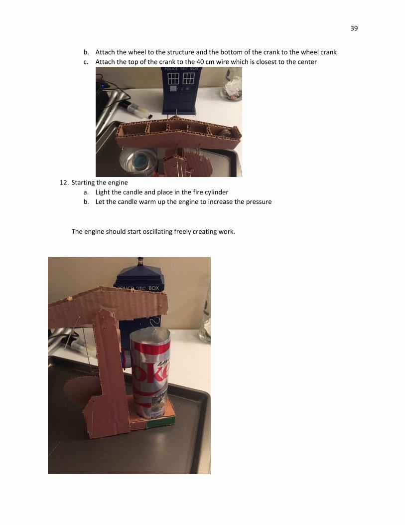
b. Attach the wheel to the structure and the bottom of the crank to the wheel crank
c. Attach the top of the crank to the 40 cm wire which is closest to the center
12. Starting the engine
a. Light the candle and place in the fire cylinder
b. Let the candle warm up the engine to increase the pressure
The engine should start oscillating freely creating work.
40
Teacher’s manual and Instructions
Introduction:
In this lab, you will be constructing a Stirling engine out of aluminum cans, cardboard and other
household items. A Stirling engine works by transferring a fixed volume of gas using heat causing
pressure to build forcing the piston down. The hot gas is then transferred to the cooled cylinder causing
the gas to cool and reduce pressure. The piston then forces the gas into the other cylinder causing
pressure and heat increase which then repeats the cycle. Stirling engines run off of any heat source with
heat greater than the cool cylinder so in this lab, we will be using a candle.
This Teacher’s Guide to a Stirling engine lab will guide a teacher to teach a class how to
understand and construct a Stirling engine. This lab takes between six and nine hours, so multiple
sessions might will be necessary to allow for glue to dry and for student to refocus. This might be best
taught as a series of afterschool ‘lab sessions’ or as a single whole day event. Take note of any
commented out suggestions denoted by an asterisk.
Materials Used:
Make sure that all materials are assembled before the lab. Students can bring in different
objects over several weeks as time provides. If this option isn’t available, these materials could be
bought at a store or online as a Stirling engine kit, but this is the more expensive option. This materials
list is for one Stirling engine, more materials will be needed if more are to be constructed for a class.
3 aluminum cans
*Soda cans work best, but soup cans can also be used.
Steel Wool
Steel Wire
2 Bottle Caps
Bottle neck (from a two liter bottle)
Fishing Line
M4 bolt/penny washer
Paperclips
Balloon
Candle
Instructions:
1. Cut out the cardboard to form the base, supports, wheel, and beam and construct.

41
*Students may need help, especially younger ones. However, the target students for this course
are high school age and this shouldn’t be an issue. For thicker cardboard n X-ACTO knife or sharp utensil
may be required if scissors are not adequate. Hot glue guns can be dangerous if not used correctly, so
be sure to instruct on safe operation so that burns can be avoided. A break after this step may be
required for glue to dry.
2. Construct the displacement cylinder
a. Drill a 6-8mm hole in the can about 30mm away from the top
*This will most likely require constant teacher supervision as power tools can be dangerous if
misused.
b. Remove the beveled part of the can on both sides (where it is tapered)
c. Drill a 6-8mm hole in the top of the bottle cap

42
d. Epoxy the cap over the hole of the can
i. Put another can inside of the can to keep it firm and stable
3. Make the displacer
a. Wrap a pen or pencil in steel wool until it is almost the size of the can
b. Remove the pen or pencil
c. Hook a paper clip with fishing line to the middle of the steel wool displacer
4. Create the diaphragm
a. Cut the neck off of a bottle and sand the edge
* This step may require some sanding and sandpaper, not included in original materials
because it is optional.
b. Cut off the top of a balloon and wrap around the cap
c. Push an M4 bolt and secure to the balloon with an M4 penny washer\

43
d. Secure the balloon with a rubber band
* This part can be tricky, so make sure students know exactly what they are doing. Glue
will need to dry after this step.
e. Screw the threads of the bottle to the cap on the can
5. Create the crank
a. Obtain two 40 cm lengths of steel wire
b. Bend the wire to create the arm
*The exact shape may take some fiddling before the final adjustment. Assure students that it
does not need to be perfect just yet.
6. Fitting the beam
a. Cut the straightened wire into two lengths of 40 mm and one about 100 mm
*Make sure that students do not cut the wire too short. Too long is better than too short as
anything shorter than required is just waste.
i. Use the 100 mm wire to connect the beam to the supports
ii. Use one of the 40 mm wire across the beam about 2 centimeters from the edge
iii. Use the other across the beam about 4 centers from the center on the other
side of the beam
b. Use a length of wire and make the piece to connect the wire to the displacer
7. Balance the beam
*This part is tricky and may take some finagling. Be familiar with this step so that students
can rely on you for any help they need. This is crucial as a bent rod will cause the engine not
to function.
a. Secure the displacer by tying the fishing line to the connector
b. Use weights to have the beam balanced with the displacer attached
44
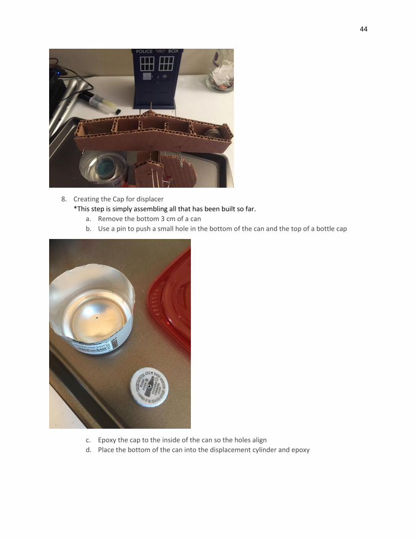
8. Creating the Cap for displacer
*This step is simply assembling all that has been built so far.
a. Remove the bottom 3 cm of a can
b. Use a pin to push a small hole in the bottom of the can and the top of a bottle cap
c. Epoxy the cap to the inside of the can so the holes align
d. Place the bottom of the can into the displacement cylinder and epoxy

45
e. Place water in the top to cool the gas (make sure the cap is completely sealed)
*This would be a good place to stop and wait for glue to dry.
9. Create the fire cylinder
a. Cut a can in half and cut a large hole in the bottom half
*This step could use a good pair of tin snips.
b. Cut the top half off at the bevel and place inside the hole for the candle to rest on
c. Place the displacement cylinder over the fire cylinder

46
10. Creating the wheel
a. Cut out a circle for the wheel
b. Place a wheel crank through the middle of the circle and connect it to the supports
*This roundness is important as it allow the circle to spin evenly and balanced.
11. Connecting the rods
a. Bend a wire to connect from the diaphragm to the crank
i. Use the washer to secure the connector to the diaphragm
ii. Use two pieces of straws to prevent the connector from sliding up and down the
crank

47
b. Attach the wheel to the structure and the bottom of the crank to the wheel crank
c. Attach the top of the crank to the 40 cm wire which is closest to the center
*If students are confused, refer then to the diagram or even have them color code when each end of the
connectors are supposed to go. For example, having the displacer rod color yellow with marker at one
end and coloring the hole where it will go yellow.
12. Starting the engine
a. Light the candle and place in the fire cylinder
b. Let the candle warm up the engine to increase the pressure
*This may take some time and some tweaking of each individual engine. Assure students that it will
most likely not work perfectly the first time. This process of revision should not take more than forty
five minutes.

48
The engine should start oscillating, freely creating work.
Summary:
Using thermodynamics and elementary laws of gasses, a stirling engine creates work by the expansion
and compression of gas using a heating and cooling source causing the movements of the pistons.
*Your students have now taken part in a STEM initiative class where they have learned about Math,
Science and Engineering and how they actively apply to the technology we see around us.
49
How to explain how a Stirling engine works (instructor material):
Basic Thermodynamic Concept:
The fundamental thermodynamic concept that is needed to understand the science behind the Stirling
engine is the ideal gas law. Air can be approximated here as an “ideal gas,” an approximation that makes
calculations easier to work with. A gas can generally be approximated as an ideal gas at normal
conditions, such as standard pressures and temperatures. The ideal gas law is expressed in the following
equation:
𝑃𝑉 = 𝑛𝑅𝑇
Where:
𝑃 = pressure of the gas
𝑉 = volume of the gas
𝑛 = amount of gas molecules (in moles)
𝑅 = ideal (or universal) gas constant
𝑇 = temperature of the gas
We can see from this equation that as the left side of the equation goes up, so must the right side (and
vice versa). With a gas that is contained in a cylinder the number of gas molecules is constant, and since
R is a constant as well we can see that pressure multiplied by volume is proportional to temperature.
𝑃𝑉 ∝ 𝑇
So when the temperature is increased, either the pressure or volume (or both) must increase
proportionally. So as air is heated in the engine cylinder, the molecules move faster and press outwards
on the walls of their container, increasing pressure. If the volume is allowed to increase (such as when
the piston expands) then the pressure doesn’t need to increase as much. This concept forms the basis of
how temperature is converted into work in the Stirling engine.
How the engine works, broken down:
1. While the displacer piston (up-and-down) is in the up position, the air in the bottom of the
cylinder heats up. As the air heats up, the power piston (left-and-right, in this case the balloon
diaphragm) is pushed out.
2. The power piston (balloon) rotates the flywheel as it is pushed out.
3. The walking beam (the horizontal beam on the top) is moved in the opposite direction.
4. The walking beam forces the displacer piston down, pushing the heated air into the top of the
cylinder.
50
5. The heated air cools in the top of the cylinder, away from the heat source. (In more complicated
Stirling engines, a heat sink or such as cool water or cooling fins can be placed around the top of
the cylinder to cool the air more quickly. This would increase the engine’s efficiency, as the air
would have a greater temperature difference between hot and cold stages.)
6. This cooled air condenses (remember PV=mRT) and “sucks” the power piston (balloon
diaphragm) back in towards the cylinder.
7. The power piston is now pulling the flywheel, continuing its rotation.
8. As the flywheel continues to rotate, it moves the walking beam back to its original position.
9. The walking beam is now raising the displacer piston to the upper position, forcing the cooled
air back down to the bottom of the cylinder.
10. The air is reheated and the cycle starts over.
51
Appendix
Alternative Heat Source Calculations:
Three AA Battery 1.8 V with 1000 mAh – 1500 mAh each
P = IV = (3 amp)(5.4 V) = 16.2 W
E = Pt
= (16.2 W)(300 sec)
= 4860 Joules
Celsius Heat Unit (CHU): ≈ 300 degrees Fahrenheit
Correction factor – 0.0315939
= P*cf
= (16.2 W)(0.0315939)
= 0. 51182 CHU/min
Two 9V Battery with 500 mAh each
P = IV
= (0.1 amps)(9 V)
= 0.9 W
E = Pt
= (0.9 W)(300 sec)
= 270 Joules
Celsius Heat Unit (CHU): ≈ 108 degrees Fahrenheit
Correction factor – 0.0315939
= P*cf
= (0.9 W)(0.0315939)
= 0.02843 CHU/min
52
References
"Applications of the Stirling Engine." Wikipedia. Wikimedia Foundation, n.d. Web. 18 Feb. 2015.
"BatterySpace.com/AA Portable Power Corp. Tel: 510-525-2328." BatterySpace.com/AA Portable Power
Corp. Tel: 510-525-2328. AA Portable Power Corp, n.d. Web. 18 Feb. 2015.
"Celsius Heat Unit (IT) Conversions." Celsius Heat Unit (IT) Conversions. Conversion-Website, n.d. Web.
18 Feb. 2015.
"Celsius-heat-unit Group | The Units and Constants Handbook at KnowledgeDoor." KnowledgeDoor.
Celsius Heat Unit Group, n.d. Web. 18 Feb. 2015.
"Earth Hour, Candles and Carbon." Physical Insights. N.p., 31 Mar. 2008. Web. 03 Mar. 2015.
"Energizer MAX Alkaline Batteries." Energizer MAX. Energizer, n.d. Web. 18 Feb. 2015.
"Sources." EPA. Environmental Protection Agency, n.d. Web. 11 Feb. 2015.
C.-H. Cheng, H.-S. Yang, L. Keong. “Theoretical and experimental study of a 300-W beta-type Stirling
engine”
Kusaka, I. (2015). Thermodynamics. In Statistical mechanics for engineers (pp. 96-97). Springer.
Larsen, Jim R. Quick and Easy Stirling Engine. Olympia, WA: Jim R. Larsen, 2012. Print.
Paulitis, Michael. "Thermodynamics and the Basics of Boltzmannian Statistical Mechanics." The History
of Thermodynamics. Rotman Summer Institute, Columbus, OH. Lecture.
Sandler, S., & Sandler, S. (2006). Chemical, biochemical, and engineering thermodynamics (4th ed.).
Hoboken, N.J.: John Wiley.
i "Connecting Rods and Spacers." Instructables.com. Web. 1 Apr. 2015. <http://www.instructables.com/id/Walking-Beam-Stirling-engine/step11/Connecting-rods-and-spacers/>. ii Williamson, David. "Soup Tin Stirling Engine." Stirling Engine. Web. 3 Apr. 2015. <http://durealeyes.com/stirling.html>.