Embed Size (px)
Citation preview

Arkon Flow SystemsArkon Flow Systems, s.r.o., Příkop 8, 602 00 Brno, Czech Republic
Correspondence address: Přízova 1-3, 602 00 Brno, Czech RepublicTel. +420 543 214 822, Tel./Fax +420 543 215 249
Enquiries /Orders /General questions: [email protected] support /brochures: [email protected]
Technical support: [email protected]
Build your own flowmeter
TCP/IP
4-20 mACURRENT
LOOP
90-250VACPOWER SUPPLY
24VDCPOWER SUPPLY
VOLTAGE 0-10VRS485RS232USB
4-20mA0-10V
90-250
VAC
24VDC
12 VDCPOWER SUPPLY
12VDC
BLUETOOTH PULSEGPRS
GPRS
BATTERY POWERED MODULAR DESIGN

4 -20 mACURRENT
LOOPLOOP
4-20mA
VOLTAGE 0-10 V0 0
0-10V
RS232
RS485
USBUSB
TCP/ IP
GPRS
GPRS
BLUETOOTHBLUETOOTH
PULSEPULSE
Advantages
The MAGX2 has an innovative modular design „Plug & Play”; it is a fi t-all, fl exible, low-cost fl ow meter all at the same time. The transmitter consists of the low-cost basic unit plus optional modules according to the end-user’s requirements. Each module is in fact a small electronic board, the size of a large stamp, which can be freely instal-led and removed from the main board in seconds.
You do not pay for options you do not want or need. You can build a flowmeter exactly as per your requirements. You can upgrade your flow meter at anytime in the future.
STANDARDTransmitterPower supply modules (12VDC /24VDC/90-250VAC)Sensor communicationmoduleCD + free SoftwareSensor
UPGRADESChoose your communicationChoose your outputsChoose your memory modules
„Built in design” for upgrades
Accuracy – ± 0.2% (0.5 - 10 m/s) of actual value
Temperature sensor – to measure temperature of the measured medium
Communication protocol – all communications via MODBUS RTU
Autocleaning – automatic electrodes cleaning
Unique design – any upgrade, extra features inside of the fl owmeter, extra protection - „Built-in design”
Graphic display – multi-language menu. Higher protection via lock-out system for touch buttons and 3 levels of passwords – User, Service, Factory settings.
Intelligent sensor design – digital communication allows communication between the transmitter and the sensor up to 500 m.
Calibration data are stored in the sensor communication module. If the transmitter is changed for whatever reason, all the calibration data will be taken from the sensor directly. No calibration download mistakes.
Datalogger
The MAGX2 uses, for data-logging purposes a standard micro Secure Digital card. This allows you to select for each application, the most suitable Secure Digital card from the market, according to your needs and require-ments. It can be installed and removed easily from MAGX2 built-in socket. Data is stored in *.csv format. Record intervals are selectable from 1 minute to 24 hours.
+softwarefree of charge

vs
OutsideInside
max 50 m max 200 m
Anywhere in the WHOLE WORLD
IN
TERNET
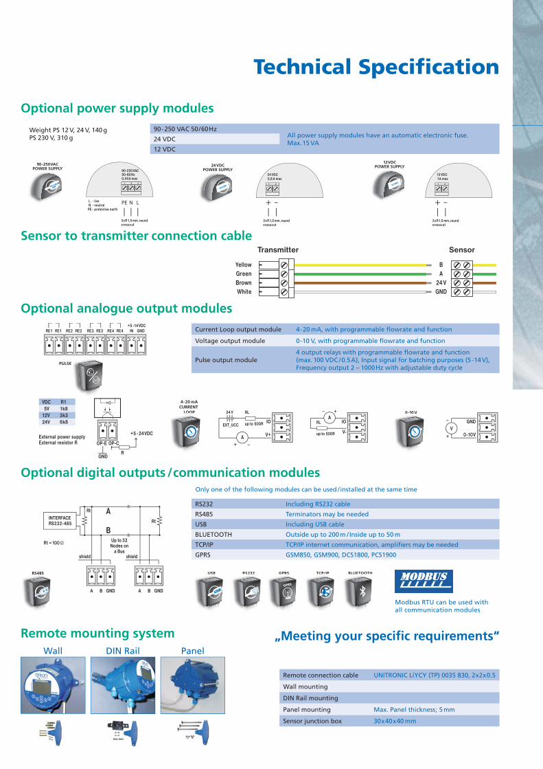
Choose your communicationModbus RTU can be used with all communication modules.
BLUETOOTHCables are not required to check your fl owmeter, within a 200 meter range.A mobile network is not required.
Standard solution for GPRS
Flowmeter plus communication cable plus mounting devide for GPRS plus extra power supply.
Our solution for GPRS
3 step installation: open, plug in, close
RS232 or USB„Old vs new computer standard“
GPRSWireless communication system, which is performed by the GPRS protocol.
The measurements can be evaluated from anywhere in the world
You will always have your fl owmeter under control
Another communication module is required for setting up the GPRS module
LowProtection
SW
GPRS
GPRS
Without loosingprotection
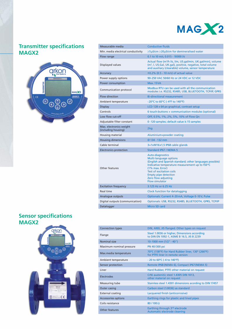
Measurable media Conductive fl uids
Min. media electrical conductivity ≥5μS/cm ≥20μS/cm for demineralised water
Flow range 0.1 to 10 m/s; 0.015 - 10000 l/s
Displayed valuesActual fl ow (m3/h l/s, l/m, US.gal/min, UK.gal/min), volume (m3, l, US.Gal, UK.gal), positive, negative, total volume and auxiliary (clearable) volume, sensor temperature
Accuracy ±0.2% (0.5 - 10 m/s) of actual value
Power supply options 90-250 VAC 50/60 Hz or 24 VDC or 12 VDC
Power consumption Max. 15VA
Communication protocolModbus RTU can be used with all the communication modules i.e. RS232, RS485, USB, BLUETOOTH, TCP/IP, GPRS
Flow direction Bi-directional measurement
Ambient temperature - 20ºC to 60ºC (- 4ºF to 140ºF)
Display LCD 128 x 64 px graphical, contrast setup
Controls 6 touch-buttons + communication modules (optional)
Low fl ow cut-off OFF, 0.5%, 1%, 2%, 5%, 10% of Flow Qn
Adjustable fi lter constant 0 - 120 samples; default value is 15 samples
Max. electronics weight (including housing)
2kg
Housing material Aluminium+powder coating
Housing dimensions Ø 134 - 132 mm
Cable terminal 3+1xM16x1,5 IP68 cable glands
Electronics protection Standard IP67 / NEMA 5
Other features
Auto-diagnosticsMulti-language options (English and Spanish standard; other languages possible)Indicative temperature measurement up to 150ºC (1% max. Error)Test of excitation coilsEmpty pipe detectionZero fl ow adjustingFlow simulator
Excitation frequency 3.125 Hz or 6.25 Hz
Real time Clock function for datalogging
Analogue outputs Optionals: Current 4-20 mA, Voltage 0 -10 V, Pulse
Digital outputs (communication) Optionals: USB, RS232, RS485, BLUETOOTH, GPRS, TCP/IP
Datalogger Micro SD card
Connection types DIN, ANSI, JIS fl anged. Other types on request
FlangeSteel 1.0036 or higher, Dimensions according to DIN EN 1092-1, ASME B 16.5, JIS B 2239
Nominal size 10-1000 mm (1/2" - 40")
Maximum nominal pressure PN 40/300 psi
Max.media temperature70ºC (158ºF) for Hard Rubber liner, 130º (266ºF) for PTFE liner in remote version
Ambient temperature - 20 to 60ºC (-4 to 140ºF)
Sensor protection Remote IP68 (NEMA 6), Compact IP67(NEMA 5)
Liner Hard Rubber, PTFE other material on request
ElectrodesCrNi austenitic steel 1.4305 DIN 1013, other material on request
Measuring tube Stainless steel 1.4301 dimensions acording to DIN 17457
Outer casing Carbon steel (1.0036) as standard
External coating Lacquered fi nish (anticorrosive)
Accessories options Earthing rings for plastic and lined pipes
Coils resistance 80 / 100Ω
Other featuresEarthing through 3rd electrodeAutomatic electrode cleaning
Sensor specifi cations MAGX2
Transmitter specifi cations MAGX2
90-250VACPOWER SUPPLY
90-250
VAC
24VDCPOWER SUPPLY
24VDC
12VDCPOWER SUPPLY
12VDC21
24 VDC0,6 A max
2xR1,5 mm, roundcrosscut
21
12 VDC 1A max
2xR1,5 mm, roundcrosscut
21 3
90-250VAC50-60 Hz0,45A max
3xR1,5 mm, roundcrosscut
L - live N - neutralPE - protective earth
PE N L
Transmitter Sensor
YellowGreenBrownWhite
BA
24VGND
RS232RS232RS485 USBUSB TCP/IPTCP/IPGPRSGPRS
GPRS
BLUETOOTHBLUETOOTH
Modbus RTU can be used withall communication modules
INTERFACERS232-485
Up to 32Nodes on
a Bus
A
B
Rt
Rt = 100 Ω
Rt
shield
A B GND A B GND
shield
4-20 mACURRENT
LOOP
4-20mA
0-10 V0 10 V
0-10V
External power supplyExternal resistor R
GND
+5 - 24VDC
OP-E OP-C
R
VDC 5V12V24V
R11k8 3k3 6k8 IO
RL24 V
up to 500REXT_UCC
V+
_
_
_
+A
IO
V-
RL
up to 500R
+A
GND
0-10V+V
RE1 RE1 RE2 RE2 RE3 RE3 RE4 RE4 IN+5 -14VDC
GND
PULSE
Wall DIN Rail Panel
Technical Specifi cation
90-250 VAC 50/60HzAll power supply modules have an automatic electronic fuse.Max. 15 VA
24 VDC
12 VDC
Current Loop output module 4-20 mA, with programmable fl owrate and function
Voltage output module 0-10 V, with programmable fl owrate and function
Pulse output module4 output relays with programmable fl owrate and function(max. 100 VDC /0.5A), Input signal for batching purposes (5 -14V),Frequency output 2 – 1000Hz with adjustable duty cycle
RS232 Including RS232 cable
RS485 Terminators may be needed
USB Including USB cable
BLUETOOTH Outside up to 200 m / Inside up to 50 m
TCP/IP TCP/IP internet communication, amplifi ers may be needed
GPRS GSM850, GSM900, DCS1800, PCS1900
Remote connection cable UNITRONIC LiYCY (TP) 0035 830, 2x2x0.5
Wall mounting
DIN Rail mounting
Panel mounting Max. Panel thickness; 5 mm
Sensor junction box 30x40x40 mm
Optional power supply modules
Sensor to transmitter connection cable
Optional analogue output modules
Optional digital outputs /communication modules
Remote mounting system „Meeting your specifi c requirements“
Weight PS 12 V, 24 V, 140 g PS 230 V, 310 g
Only one of the following modules can be used /installed at the same time

C2C1
E2GND E1
R_
+
Signal
_V < 35 VDCl < 50 mA
V
Positive Pulse Negative Pulse
OV
V
OV
R
_
+Signal
_V < 35 VDCl < 50 mA
Advantages
New Arkon MAGB1 battery powered fl owmeter:Now is possible to install a reliable fl owmeter virtually anywhere without sacrifi cing accuracy or performance. Accuracy is ± 0.5% of actual value. No mains power required. Suitable for irrigation, remote applications any other application where power supply lines are diffi cult or expensive to install.
Features
Battery powered electromagnetic fl owmeter Accuracy: ± 0.5% of actual value Empty pipe detection, automatically turns off the excitation to prolong battery life Graphic display and keypad for simple operation and instant access to information about 4 totalizers: total +,
total -, total, aux. Modbus RTU communication protocol via USB Standard USB interface for confi guration and data collection using MAGB1 software Easy access to data on-site Isolated binary output (pulse per liters or alarm or fl owrate functions) Error detection Datalogger - 1820 records, selectable interval of logging (5 min - 24 h)
Battery
Binary output
Sensor to transmitter connection cable
Unit powered by 2 x 3.6 V batteries placed inside the transmitter (see drawing)
Battery life up to 5 years Battery conservation when the pipe is empty Adjustable fi lter constant 1 – 30 samples Minimized inlet and outlet installation requirements Maintenance free CE certifi cation Two built-in earthing electrodes No moving parts in measuring tube All units include a calibration certifi cate issued by an independent
calibration rig, traceable to international standards, and calibration data is stored inside the instrument.
Tran
smit
ter
Sen
sor
C1 - Coil1C2 - Coil2GND - GroundElectrode - 1Electrode - 2
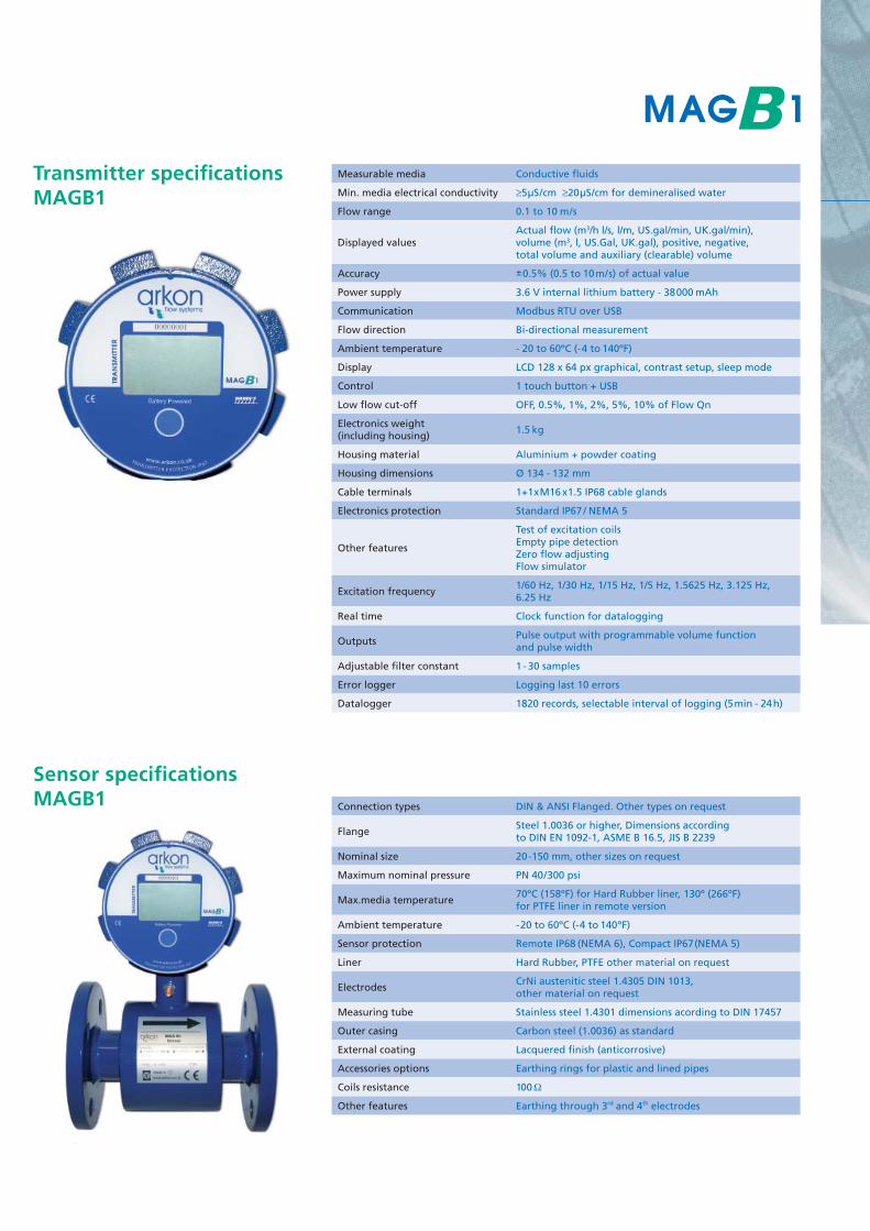
Measurable media Conductive fl uids
Min. media electrical conductivity ≥5μS/cm ≥20μS/cm for demineralised water
Flow range 0.1 to 10 m/s
Displayed valuesActual fl ow (m3/h l/s, l/m, US.gal/min, UK.gal/min), volume (m3, l, US.Gal, UK.gal), positive, negative, total volume and auxiliary (clearable) volume
Accuracy ±0.5% (0.5 to 10m/s) of actual value
Power supply 3.6 V internal lithium battery - 38000 mAh
Communication Modbus RTU over USB
Flow direction Bi-directional measurement
Ambient temperature - 20 to 60ºC (-4 to 140ºF)
Display LCD 128 x 64 px graphical, contrast setup, sleep mode
Control 1 touch button + USB
Low fl ow cut-off OFF, 0.5%, 1%, 2%, 5%, 10% of Flow Qn
Electronics weight (including housing)
1.5 kg
Housing material Aluminium + powder coating
Housing dimensions Ø 134 - 132 mm
Cable terminals 1+1xM16 x1.5 IP68 cable glands
Electronics protection Standard IP67 / NEMA 5
Other features
Test of excitation coilsEmpty pipe detectionZero fl ow adjustingFlow simulator
Excitation frequency1/60 Hz, 1/30 Hz, 1/15 Hz, 1/5 Hz, 1.5625 Hz, 3.125 Hz, 6.25 Hz
Real time Clock function for datalogging
OutputsPulse output with programmable volume function and pulse width
Adjustable fi lter constant 1 - 30 samples
Error logger Logging last 10 errors
Datalogger 1820 records, selectable interval of logging (5min - 24h)
Connection types DIN & ANSI Flanged. Other types on request
FlangeSteel 1.0036 or higher, Dimensions according to DIN EN 1092-1, ASME B 16.5, JIS B 2239
Nominal size 20-150 mm, other sizes on request
Maximum nominal pressure PN 40/300 psi
Max.media temperature70ºC (158ºF) for Hard Rubber liner, 130º (266ºF) for PTFE liner in remote version
Ambient temperature - 20 to 60ºC (-4 to 140ºF)
Sensor protection Remote IP68 (NEMA 6), Compact IP67(NEMA 5)
Liner Hard Rubber, PTFE other material on request
ElectrodesCrNi austenitic steel 1.4305 DIN 1013, other material on request
Measuring tube Stainless steel 1.4301 dimensions acording to DIN 17457
Outer casing Carbon steel (1.0036) as standard
External coating Lacquered fi nish (anticorrosive)
Accessories options Earthing rings for plastic and lined pipes
Coils resistance 100Ω
Other features Earthing through 3rd and 4th electrodes
Sensor specifi cations MAGB1
Transmitter specifi cations MAGB1

Recommended position for sensor installation
Sensor installation requirements
Proper installation is extremely important in order for your fl owmeter to work correctly. There are minimum sen-sor installation requirements that need to be respected at all times. Please note that Arkon cannot warranty any installation which does not comply with these requirements:
Horizontal standard mountingThe sensor tube must always remain full. The best way to achieve this is to locate the sensor in a low section of pipe, see the fol-lowing picture.It is mandatory to install the sensor in a section of straight pipe with at least 5 times the pipe diameter before sensor and 3 times after sensor.
Pipe reducersIf the pipe diameter is not the same as the diameter of sensor, then pipe reducers can be used. So as not to lose accuracy of the measurement, the slope of reducers should not exceed 8°.
Vertical mountingWhen the sensor is mounted on a vertical section of pipe, the fl ow direction must be upwards. In the case of a downward fl ow direction, air bubbles can collect in the sensor and the measure-ment could be unstable and inaccurate.
5xD 3xD
5xD3xD

PumpsNever install the sensor on the suction side of a pump or on a section of pipe where a vacuum is possible.
ValvesSuitable location of a shutoff valve is downstream of a sensor.
Removal during maintenanceIf the application requires removal of the sensor for periodic maintenance, it is recommended to install a bypass section as the drawing below.
EarthingAll fl owmeters must be earthed. Maximum resistance of the sensor to earth is <1 ohm. All the components in the loop, including fl owmeter, pumps (especially submersible) valves, pipework, tanks and medium, should all be at the same earth potential. Problems can occur when different potentials are present which can happen, especially with submersible pumps. On applications with metal pipes and tanks it is enough to earth the fl owmeter to the pipe’s fl anges. On ap-plications where pipes and tanks are manufactured from plastic it is necessary that earthing rings are also installed to ensure the fl owmeter works correctly.
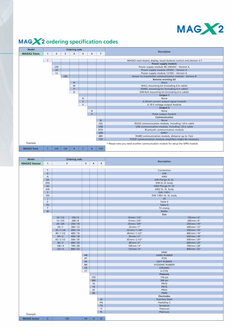
ordering specifi cation codesModel Ordering code
DescriptionMAGX2 Trans. 1 2 3 4 5 6 7
T MAGX2 main board, display, touch buttons control unit,Version V.7Power supply module
230 Power supply module 90-250VAC - Version 4. 24 Power supply module 24VDC - Version 4.12 Power supply module 12VDC - Version 4.
CM Sensor to transmitter communication module - Version 8Remote monting kit
N NoneW WALL mounting kit (including 6 m cable)P PANEL mounting kit (including 6 m cable)D DIN-Rail mounting kit (including 6 m cable)
Output 1N NoneC 4-20 mA current output signal moduleV 0 -10 V voltage output module
Output 2N NoneP Pulse output module
CommunicationN None
232 RS232 communication module, including 1,8 m cableUSB USB communication module, including 1,8 m cableBTO Bluetooth communication moduleGPR GPRS*485 RS485 communication module, distance up to 1 kmTCP TCP/IP communication module, amplifi ers might be necessary
Example * Please note you need another communication module for setup the GPRS module
MAGX2 Trans. T 230 CM N C N USB
Model Ordering codeDescription
MAGX2 Sensor 1 2 3 4 5
T ConnectionD DIN A ANSIDS DIN Flange St. St.DSS DIN St. St. bodyAS ANSI Flange St. St.ASS ANSI St. St. body
S DIN 11851SSS DIN 11851 St. St. bodyJ JISE Table E
TD Table DT Tri-clampW Wafer
Size10 / 1/2 150 / 6 10 mm / 1/2" 150 mm / 6"15 / 2/3 200 / 8 15 mm / 2/3" 200 mm / 8"20 / 3/4 250 / 10 20 mm / 3/4" 250 mm / 10"25 / 1 300 / 12 25 mm / 1" 300mm / 12"
32 / 1.1/4 350 / 14 32 mm / 1.1/4" 350mm / 14"40 / 1.1/2 400 / 16 40mm / 1.1/2" 400 mm / 16"
50 / 2 450 / 18 50 mm / 2" 450 mm / 18"65 / 2.1/2 500 / 20 65mm / 2.1/2" 500 mm / 20"
80 / 3 600 / 24 80 mm / 3" 600 mm / 24"100 / 4 700 / 28 100 mm / 4" 700 mm / 28"125 / 5 800 / 32 125 mm / 5" 800 mm / 32"
LinerHR HARD RUBBERPT PTFESR SOFT RUBBERNR HYGIENIC RUBBERCR CERAMICCT E-CTFE
Pressure150 150 psi300 300 psi10 PN1016 PN1625 PN2540 PN40
ElectrodesSS Stainless SteelHA Hastelloy CTA TantalumTI TitaniumPL Platinum
Example
MAGX2 Sensor D 100 HR 16 SS

ordering specifi cation codesModel Ordering code
DescriptionMAGB1 1 2 3 4 5 6
Version
C Compact
W Remote: WALL mounting kit (including 6 m cable)
P Remote: PANEL mounting kit (including 6 m cable)
R Remote: DIN-Rail mounting kit (including 6 m cable)
Connection type
D DIN
A ANSI
Size
20 / 3/4 20 mm / 3/4“
25 / 1 25 mm / 1"
32 / 1.1/4 32 mm / 1.1/4"
40 / 1.1/2 40mm / 1.1/2"
50 / 2 50 mm / 2"
65 / 2.1/2 65mm / 2.1/2"
80 / 3 80 mm / 3"
100 / 4 100 mm / 4"
125 / 5 125mm / 5"
150 / 6 150 mm / 6“
Liner material
HR HARD RUBBER
SR SOFT RUBBER
PT PTFE
Pressure
150 150 psi
300 300 psi
10 PN10
16 PN16
25 PN25
40 PN40
Electrodes
SS Stainless Steel
HA Hastelloy C
TA Tantalum
TI Titanium
PL Platinum
Example
MAGB1 C D 100 HR 16 SS
Please note that any order placed without details regarding required fl ow-range (for example: 0-50m3/hr or 0 -100 l/s) and Pulse Output (for example pulse/m3 or 1 pulse/litre) will be processed with standard settings.
Please note for applications where all pipes and tanks are manufactured from plastic, earthing rings are recommended to ensure the accuracy of the measurements.
When placing orders where the application may diffi cult, such as aggressive and corrosive liquids. Arkon will expect you to advise us about the specifi cs of the installation on your enquiry form or order, to enable Arkon staff to consider if the requested products are indeed suitable.
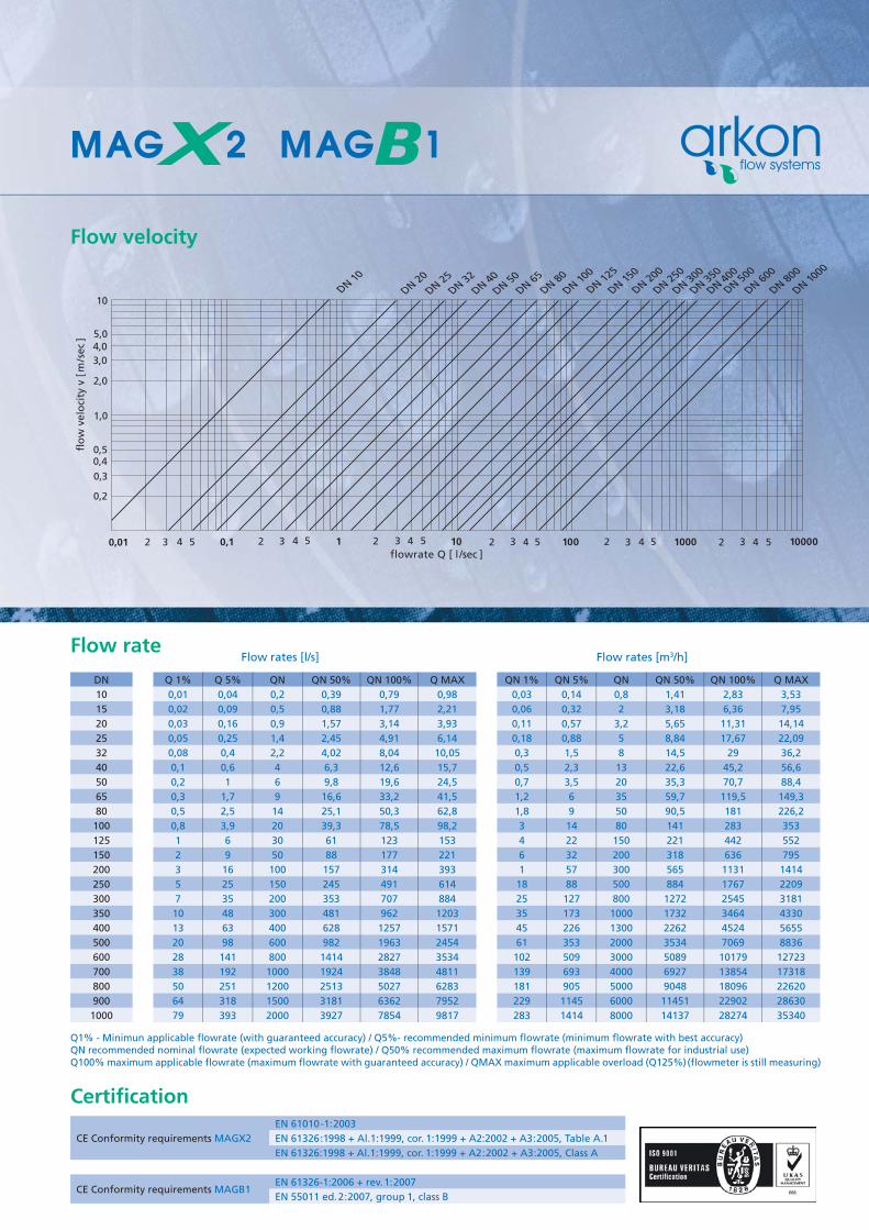
flowrate Q [ l /sec ]
DN 10
DN 20
DN 25
DN 32
DN 40
DN 50DN 65
DN 80
DN 100
DN 125
DN 150
DN 200
DN 250
DN 300
DN 350
DN 400
DN 500
DN 600
DN 800
DN 1000
flo
w v
elo
city
v [
m/s
ec ]
10
5,04,03,0
2,0
1,0
0,50,4
0,3
0,2
0,01 2 3 4 5 0,1 2 3 4 5 1 2 3 4 5 10 2 3 4 5 100 2 3 4 5 1000 2 3 4 5 10000
Flow velocity
Flow rate Flow rates [l/s] Flow rates [m3/h]
DN Q 1% Q 5% QN QN 50% QN 100% Q MAX QN 1% QN 5% QN QN 50% QN 100% Q MAX
10 0,01 0,04 0,2 0,39 0,79 0,98 0,03 0,14 0,8 1,41 2,83 3,53
15 0,02 0,09 0,5 0,88 1,77 2,21 0,06 0,32 2 3,18 6,36 7,95
20 0,03 0,16 0,9 1,57 3,14 3,93 0,11 0,57 3,2 5,65 11,31 14,14
25 0,05 0,25 1,4 2,45 4,91 6,14 0,18 0,88 5 8,84 17,67 22,09
32 0,08 0,4 2,2 4,02 8,04 10,05 0,3 1,5 8 14,5 29 36,2
40 0,1 0,6 4 6,3 12,6 15,7 0,5 2,3 13 22,6 45,2 56,6
50 0,2 1 6 9,8 19,6 24,5 0,7 3,5 20 35,3 70,7 88,4
65 0,3 1,7 9 16,6 33,2 41,5 1,2 6 35 59,7 119,5 149,3
80 0,5 2,5 14 25,1 50,3 62,8 1,8 9 50 90,5 181 226,2
100 0,8 3,9 20 39,3 78,5 98,2 3 14 80 141 283 353
125 1 6 30 61 123 153 4 22 150 221 442 552
150 2 9 50 88 177 221 6 32 200 318 636 795
200 3 16 100 157 314 393 1 57 300 565 1131 1414
250 5 25 150 245 491 614 18 88 500 884 1767 2209
300 7 35 200 353 707 884 25 127 800 1272 2545 3181
350 10 48 300 481 962 1203 35 173 1000 1732 3464 4330
400 13 63 400 628 1257 1571 45 226 1300 2262 4524 5655
500 20 98 600 982 1963 2454 61 353 2000 3534 7069 8836
600 28 141 800 1414 2827 3534 102 509 3000 5089 10179 12723
700 38 192 1000 1924 3848 4811 139 693 4000 6927 13854 17318
800 50 251 1200 2513 5027 6283 181 905 5000 9048 18096 22620
900 64 318 1500 3181 6362 7952 229 1145 6000 11451 22902 28630
1000 79 393 2000 3927 7854 9817 283 1414 8000 14137 28274 35340
Q1% - Minimun applicable fl owrate (with guaranteed accuracy) / Q5%- recommended minimum fl owrate (minimum fl owrate with best accuracy)QN recommended nominal fl owrate (expected working fl owrate) / Q50% recommended maximum fl owrate (maximum fl owrate for industrial use)Q100% maximum applicable fl owrate (maximum fl owrate with guaranteed accuracy) / QMAX maximum applicable overload (Q125%)(fl owmeter is still measuring)
Certifi cation
CE Conformity requirements MAGX2
EN 61010-1:2003
EN 61326:1998 + Al.1:1999, cor. 1:1999 + A2:2002 + A3:2005, Table A.1
EN 61326:1998 + Al.1:1999, cor. 1:1999 + A2:2002 + A3:2005, Class A
CE Conformity requirements MAGB1EN 61326-1:2006 + rev. 1:2007
EN 55011 ed.2:2007, group 1, class B